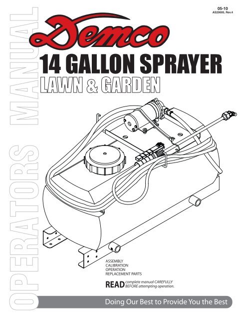
AS20005 - 14 Gallon Pro Series Manual - Demco Products
AS20005 - 14 Gallon Pro Series Manual - Demco Products
AS20005 - 14 Gallon Pro Series Manual - Demco Products
You also want an ePaper? Increase the reach of your titles
YUMPU automatically turns print PDFs into web optimized ePapers that Google loves.
Page 1<br />
05-10<br />
<strong>AS20005</strong>, Rev.4
Thank you for purchasing a <strong>Demco</strong> sprayer. We feel you have made a wise choice and hope you<br />
are completely satisfi ed with your new sprayer. If you have any questions regarding the applications<br />
of certain solutions or chemicals, contact your chemical supplier and follow chemical manufacturer<br />
recommendations as well as all licensing and use restrictions or regulations.<br />
WARNING: TO AVOID PERSONAL INJURY OR PROPERTY DAMAGE, OBSERVE<br />
FOLLOWING INSTRUCTIONS:<br />
Chemicals are dangerous. Know exactly what you’re going to do and what<br />
is going to happen before attempting to work with these products. Improper<br />
selection or use can injure people, animals, plants and soil.<br />
Always wear protective clothing such as coveralls, goggles and gloves when<br />
working with chemicals or sprayer.<br />
Be sure to dispose of all unused chemicals or solutions in a proper and<br />
ecologically sound manner.<br />
GENERAL INFORMATION<br />
1. Whenever terms “LEFT” and “RIGHT” are used in<br />
this manual it means from a position behind sprayer<br />
and facing forward.<br />
2. When placing a parts order, refer to this manual for<br />
proper part numbers and place order by PART NO.<br />
and DESCRIPTION.<br />
Table of Contents<br />
General information ............................................................................................................. 2<br />
Warranty Registration .........................................................................................................3-4<br />
Safety, Signal Words ........................................................................................................... 5<br />
Equipment Safety Guidelines .............................................................................................. 6<br />
Lighting and Marking ........................................................................................................... 6<br />
Safety Sign Care ................................................................................................................. 6<br />
Safety Sign Locations .........................................................................................................7<br />
Transport Operations ........................................................................................................... 8<br />
Remember .......................................................................................................................... 8<br />
Before Operation ................................................................................................................. 8<br />
During Operation ................................................................................................................. 9<br />
Following Operation ............................................................................................................ 9<br />
Performing Maintenance .................................................................................................... 10<br />
Bolt Torque ......................................................................................................................... 11<br />
<strong>14</strong> <strong>Gallon</strong> Sprayer (SM<strong>14</strong>) Breakdown and Parts List ......................................................12-13<br />
HYMB85 Mounting Brackets Breakdown and Parts List ................................................... <strong>14</strong><br />
80” Boom Assembly (80B10) Breakdown and Parts List .................................................. 15<br />
12’ Boom Assembly (<strong>14</strong>4-B<strong>14</strong>) Breakdown and Parts List ............................................... 16<br />
Electric Pump breakdown and Parts List .......................................................................... 17<br />
Sprayer Calibration ............................................................................................................. 18<br />
Sprayer Checklist .............................................................................................................. 19<br />
Page 2
4010 320th Street • Box 189 • Boyden, Iowa 51234<br />
Toll Free 800-54DEMCO (800-543-3626) • FAX 800-845-6420<br />
www.demco-products.com<br />
Warranty Registration<br />
Very<br />
Satisfied<br />
Satisfied<br />
Dissatisfied<br />
Ag<br />
RV<br />
Rental<br />
Brakes<br />
Marine<br />
❍<br />
❍<br />
❍<br />
❍<br />
❍<br />
Very<br />
Dissatisfied<br />
How satisfied are you with our product? ❍ ❍ ❍ ❍<br />
How satisfied are you with the dealership/distributor sales staff? ❍ ❍ ❍ ❍<br />
Dealer/Distributor Name City State<br />
How satisfied are you with the company sales staff? ❍ ❍ ❍ ❍<br />
How satisfied are you with the delivery? ❍ ❍ ❍ ❍<br />
Did you have any contact with a <strong>Demco</strong> Representative? YES NO<br />
If YES, how satisfied were you? ❍ ❍ ❍ ❍<br />
I would recommend this product to my family and friends. YES NO<br />
Would you purchase again from DEMCO? YES NO<br />
Since taking delivery, have you been contacted by the dealer? YES NO<br />
Did you have any problems with this DEMCO product? YES NO<br />
If YES, are you satisfied with the company’s resolution of your problem? ❍ ❍ ❍ ❍<br />
Please list the specific source of information prompting this purchase.<br />
After purchasing this product, do you see any needed product improvement?<br />
If yes, what improvement?<br />
What other products would you like to see DEMCO offer?<br />
Comments<br />
Owner’s Name:<br />
Mailing Address:<br />
City: State: Zip Code:<br />
Model#:<br />
Serial #:<br />
Purchase Date:<br />
Owner’s Signature:<br />
Please return to DEMCO By FAX or tri-folding this form to the backside, it is pre-addressed.<br />
Page 3
Postage<br />
<strong>Demco</strong><br />
4010 320th Street, Box 189<br />
Boyden, Iowa 51234<br />
Page 4
SAFETY<br />
TAKE NOTE! THIS SAFETY ALERT SYMBOL FOUND THROUGHOUT THIS<br />
MANUAL IS USED TO CALL YOUR ATTENTION TO INSTRUCTIONS INVOLVING<br />
YOUR PERSONAL SAFETY AND SAFETY OF OTHERS. FAILURE TO FOLLOW<br />
THESE INSTRUCTIONS CAN RESULT IN INJURY OR DEATH.<br />
THIS SYMBOL MEANS<br />
ATTENTION<br />
BECOME ALERT<br />
YOUR SAFETY IS INVOLVED!<br />
SIGNAL WORDS<br />
This manual uses of the following signal words--<br />
DANGER, WARNING, and CAUTION-- with safety<br />
messages. The appropriate signal word has been<br />
selected using the following guidelines.<br />
DANGER:<br />
Indicates an imminently hazardous situation that,<br />
if not avoided, will result in death or serious injury.<br />
This signal word is to be limited to the most extreme<br />
situations typically for machine components which,<br />
for functional purposes, cannot be guarded.<br />
WARNING:<br />
Indicates a potentially hazardous situation that, if<br />
not avoided, could result in death or serious injury,<br />
and includes hazards that are exposed when<br />
guards are removed. It may also be used to alert<br />
against unsafe practices.<br />
CAUTION:<br />
Indicates a potentially hazardous situation that,<br />
if not avoided, may result in minor or moderate<br />
injury. It may also be used to alert against unsafe<br />
practices.<br />
If you have questions not answered in this manual , require additional copies, or if your manual is damaged,<br />
please contact your dealer or <strong>Demco</strong>, 4010 320th Street, P.O. Box 189, Boyden, IA 51234 ph: (712)<br />
725-2311 or Toll Free: 1-800-543-3626 Fax: (712) 725-2380 http://www.demco-products.com<br />
Page 5
SAFETY...YOU CAN LIVE WITH IT<br />
EQUIPMENT SAFETY GUIDELINES<br />
Every year many accidents occur which could have been avoided by a few seconds of thought and a more<br />
careful approach to handling equipment. You, the operator, can avoid many accidents by observing the following<br />
precautions in this section. To avoid personal injury, study the following precautions and insist those working with<br />
you, or you yourself, follow them.<br />
In order to provide a better view, certain illustrations in this manual may show an assembly with a safety shield<br />
removed. However, equipment should never be operated in this condition. Keep all shields in place. If shield<br />
removal becomes necessary for repairs, replace shield prior to use.<br />
Replace any caution, warning, danger or instruction safety decal that is not readable or is missing. Location of<br />
such decals is indicated in this booklet.<br />
Do not attempt to operate this sprayer under the infl uence of alcohol or drugs.<br />
Review safety instructions with all users.<br />
Operator should be a responsible adult. DO NOT ALLOW PERSONS TO OPERATE OR ASSEMBLE THIS UNIT<br />
UNTIL THEY HAVE DEVELOPED A THOROUGH UNDERSTANDING OF SAFETY PRECAUTIONS AND HOW<br />
IT WORKS.<br />
Do not paint over, remove, or deface any safety signs or warning decals on your sprayer. Observe all safety signs<br />
and practice instructions on them.<br />
Never exceed limits of a piece of machinery. If its ability to do a job, or to do so safely is in question-DON’T TRY<br />
IT.<br />
LIGHTING AND MARKING<br />
It is the responsibility of customer to know lighting and marking requirements of local highway authorities and to<br />
install and maintain sprayer to provide compliance with regulations. Add extra lights when transporting at night or<br />
during periods of limited visibility.<br />
SAFETY SIGN CARE<br />
• Keep safety signs clean and legible at all times.<br />
• Replace safety signs that are missing or have become illegible.<br />
• Replacement parts that displayed a safety sign should also display current sign.<br />
• Safety signs are available from your distributor, dealer parts department, or factory.<br />
How to install safety signs:<br />
• Be sure that installation area is clean and dry.<br />
• Decide on exact position before you remove backing paper.<br />
• Remove smallest portion of split backing paper.<br />
• Align decal over specifi ed area and carefully press small portion with<br />
exposed sticky backing in place.<br />
• Slowly peel back remaining paper and carefully smooth decal into place.<br />
• Air pockets can be pierced with a pin and smoothed out using piece of backing paper.<br />
Page 6
SAFETY SIGN LOCATIONS<br />
Types of safety sign and locations on equipment are shown in illustration below. Good safety<br />
requires that you familiarize yourself with various safety signs, type of warning, and area or<br />
particular function related to that area, that requires your SAFETY AWARENESS.<br />
A<br />
B<br />
A. AB210<strong>14</strong> - Warning: Refer to chemical<br />
supplier and manufacturer Qty. 1<br />
B. AA21012 - Small <strong>Demco</strong> Qty. 2<br />
Page 7
TRANSPORT OPERATIONS<br />
• Adopt safe driving practices:<br />
- Always drive at a safe speed relative to local conditions and ensure that your speed is low enough for an<br />
emergency stop. Keep speed to a minimum.<br />
- Reduce speed prior to turns to avoid risk of overturning.<br />
- Always keep ATV in gear to provide engine braking when going downhill. Do not coast.<br />
- Do not drink and drive!<br />
• Comply with state and local laws governing the use of ATV’s. Do not use the ATV on highway and streets if<br />
prohibited.<br />
• Use approved accessory lighting and fl ags and necessary warning devices if using the ATV on streets or<br />
highways. Always use fl ashing amber lights or slow moving vehicle emblem if operating on streets or highways.<br />
• Use of flashing amber lights is acceptable in most localities. However, some localities prohibit their use. Local laws<br />
should be checked for all highway lighting and marking requirements.<br />
• Be a safe and courteous driver at all times.<br />
• Watch for obstructions overhead and side to side while transporting.<br />
• Always operate your ATV in a position to provide maximum visibility at all times. Make allowances for increased<br />
length and weight of sprayer when making turns, stopping, etc.<br />
REMEMBER<br />
Your best assurance against accidents is a careful and responsible operator. If there is any portion of this manual<br />
or function you do not understand, contact your local authorized dealer or manufacturer.<br />
BEFORE OPERATION:<br />
• Carefully study and understand this manual.<br />
• Do not wear loose-fi tting clothing which may catch in moving parts.<br />
• Always wear protective clothing and substantial shoes.<br />
• It is recommended that suitable protective hearing and eye protection be worn.<br />
• The operator may come in contact with certain materials which may require specifi c safety equipment relative to<br />
handling of such materials. (Examples: extremely dusty, molds, fungus, bulk fertilizers, etc.)<br />
• Give sprayer a visual inspection for any loose bolts, worn parts, or cracked welds, and make necessary repairs.<br />
Follow maintenance safety instructions included in this manual.<br />
• Be sure there are no tools lying on or in equipment<br />
• Do not use sprayer until you are sure that area is clear, especially around children and animals.<br />
• Don’t hurry learning process or take sprayer for granted. Ease into it and become familiar with your new<br />
equipment.<br />
• Practice operation of your equipment and its attachments. Completely familiarize yourself and other operators<br />
with its operation before using.<br />
Page 8
DURING OPERATION<br />
• Beware of bystanders, PARTICULARLY CHILDREN! Always look around to make sure that it is safe to start<br />
engine of towing vehicle or move sprayer. This is particularly important with higher noise levels and quiet cabs,<br />
as you may not hear people shouting.<br />
• NO PASSENGERS ALLOWED- Do not carry passengers anywhere on sprayer.<br />
• Keep hands and clothing clear of moving parts.<br />
• Do not clean, lubricate, or adjust your sprayer while it is moving.<br />
• When halting operation, even periodically, set vehicles brakes, shut off engine, and remove ignition key.<br />
• Be especially observant of operating area and terrain- watch for holes, rocks, or other hidden hazards.<br />
Always inspect area prior to operation.<br />
- DO NOT operate near edge of drop-offs or banks.<br />
- DO NOT operate on steep slopes as overturn may result.<br />
- Operate up and down (not across) intermediate slopes. Avoid sudden starts and stops.<br />
• Pick the most level possible route when transporting across fi elds. Avoid edges of ditches, gullies, and<br />
steep hillsides.<br />
• Be extra careful when working on inclines.<br />
• Periodically clear sprayer of brush, twigs, or other materials to prevent buildup of dry combustible materials.<br />
• Maneuver tractor or towing vehicle at safe speeds.<br />
• Avoid loose gravel, rocks, and holes; they can be dangerous for sprayer operation or movement.<br />
• Do not walk or work under raised components or attachments unless securely supported.<br />
• Keep all bystanders, pets, and livestock clear of work area.<br />
• Never stand alongside of unit with engine running or attempt to start engine and/or operate machine while<br />
standing alongside of unit.<br />
• Never leave running equipment attachments unattended.<br />
• As a precaution, always recheck hardware on equipment following every 100 hours of operation. Correct all<br />
problems. Follow maintenance safety procedures.<br />
FOLLOWING OPERATION<br />
• Following operation, or when unhitching, stop tractor or towing vehicle, set brakes, shut off engine and remove<br />
ignition key.<br />
• Store unit in an area away from human activity.<br />
• Do not park equipment where it will be exposed to livestock for long periods of time. Damage and livestock<br />
injury could result.<br />
• Do not permit children to play on or around stored unit.<br />
• Make sure all parked machines are on a hard, level surface and engage all safety devices.<br />
Page 9
PERFORMING MAINTENANCE<br />
• Good maintenance is your responsibility. Poor maintenance is an invitation to trouble.<br />
• Make sure there is plenty of ventilation. Never operate engine of towing vehicle in a closed building.<br />
Exhaust fumes may cause asphyxiation.<br />
• Before working on this machine, stop towing vehicle, set brakes, disengage PTO and all power drives,<br />
shut off engine and remove ignition key.<br />
• Be certain all moving parts and attachments have come to a complete stop before attempting to perform<br />
maintenance.<br />
• Always use a safety support and block wheels. Never use a jack to support machine.<br />
• Always use proper tools or equipment for job at hand.<br />
• Use extreme caution when making adjustments.<br />
• Follow torque chart on page 11 in this manual when tightening bolts and nuts.<br />
• Never use your hands to locate a hydraulic leak on attachments. Use a small piece of cardboard or wood.<br />
Hydraulic fl uid escaping under pressure can penetrate skin.<br />
• Openings in skin and minor cuts are susceptible to infection from hydraulic fl uid.<br />
Without immediate medical treatment, serious infection and reactions can occur.<br />
• When disconnecting hydraulic lines, shut off hydraulic supply and relieve all hydraulic pressure.<br />
• Replace all shields and guards after servicing and before moving.<br />
• After servicing, be sure all tools, parts and service equipment are removed.<br />
• Do not allow grease or oil to build up on any step or platform.<br />
• When replacing bolts refer to owners manual.<br />
• Refer to bolt torque chart on page 11 for head identifi cation marking.<br />
• Where replacement parts are necessary for periodic maintenance and servicing, genuine factory<br />
replacement parts must be used to restore your equipment to original specifi cations. Manufacturer will not<br />
claim responsibility for use of unapproved parts or accessories and other damages as a result of their use.<br />
• If equipment has been altered in any way from original design, manufacturer does not accept any liability for<br />
injury or warranty.<br />
• A fi re extinguisher and fi rst aid kit should be kept readily accessible while performing maintenance on this<br />
sprayer.<br />
Page 10
BOLT TORQUE<br />
TORQUE DATA FOR STANDARD NUTS, BOLTS, AND CAPSCREWS.<br />
Tighten all bolts to torques specifi ed in chart unless otherwise noted. Check tightness of bolts<br />
periodically, using bolt chart as guide. Replace hardware with same grade bolt.<br />
NOTE: Unless otherwise specifi ed, high-strength Grade 5 hex bolts are used throughout<br />
assembly of equipment.<br />
Bolt Torque for Standard bolts *<br />
Torque Specifications<br />
GRADE 2 GRADE 5 GRADE 8<br />
“A” lb-ft (N.m) lb-ft (N.m) lb-ft (N.m)<br />
1/4” 6 (8) 9 (12) 12 (16)<br />
5/16” 10 (13) 18 (25) 25 (35)<br />
3/8” 20 (27) 30 (40) 45 (60)<br />
7/16” 30 (40) 50 (70) 80 (110)<br />
1/2” 45 (60) 75 (100) 115 (155)<br />
9/16” 70 (95) 115 (155) 165 (220)<br />
5/8” 95 (130) 150 (200) 225 (300)<br />
3/4” 165 (225) 290 (390) 400 (540)<br />
7/8” 170 (230) 420 (570) 650 (880)<br />
1” 225 (300) 630 (850) 970 (1310)<br />
Bolt Torque for Metric bolts *<br />
Torque fi gures indicated are valid for<br />
non-greased or non-oiled threads and<br />
heads unless otherwise specified.<br />
Therefore, do not grease or oil bolts or<br />
capscrews unless otherwise specifi ed<br />
in this manual. When using locking<br />
elements, increase torque values<br />
by 5%.<br />
* GRADE or CLASS value for bolts<br />
and capscrews are identifi ed by their<br />
head markings.<br />
CLASS 8.8 CLASS 9.8 CLASS 10.9<br />
“A” lb-ft (N.m) lb-ft (N.m) lb-ft (N.m)<br />
6 9 (13) 10 (<strong>14</strong>) 13 (17)<br />
7 15 (21) 18 (24) 21 (29)<br />
8 23 (31) 25 (34) 31 (42)<br />
10 45 (61) 50 (68) 61 (83)<br />
12 78 (106) 88 (118) 106 (<strong>14</strong>4)<br />
<strong>14</strong> 125 (169) <strong>14</strong>0 (189) 170 (230)<br />
16 194 (263) 216 (293) 263 (357)<br />
18 268 (363) -- -- 364 (493)<br />
20 378 (513) -- -- 515 (689)<br />
22 516 (699) -- -- 702 (952)<br />
24 654 (886) -- -- 890 (1206)<br />
GRADE-2 GRADE-5<br />
GRADE-8<br />
CLASS 8.8 CLASS 9.8 CLASS 10.9<br />
8.8 9.8 10.9<br />
Page 11
<strong>14</strong> GALLON SPRAYER (SM<strong>14</strong>) PARTS BREAKDOWN<br />
2<br />
5<br />
6<br />
39<br />
6<br />
22<br />
19<br />
<strong>14</strong><br />
7<br />
8<br />
15<br />
16<br />
1718<br />
9<br />
4<br />
12<br />
20<br />
13<br />
10<br />
3<br />
11<br />
37<br />
38<br />
21<br />
26<br />
27<br />
29<br />
28<br />
Positive Wire<br />
20<br />
19<br />
23<br />
30<br />
36<br />
36<br />
Positive Wire<br />
24<br />
25<br />
1<br />
34<br />
Positive Wire<br />
Negative Wire<br />
2<br />
31<br />
Negative Wire<br />
35<br />
Included with switch<br />
33<br />
32<br />
Page 12
<strong>14</strong> GALLON SPRAYER (SM<strong>14</strong>) PARTS LIST<br />
REF.<br />
NO.<br />
PART<br />
NO. QTY. DESCRIPTION<br />
1. 09244 1 Replacement Fuse Holder<br />
2. 09272 1 Replacement 20 Amp Fuse<br />
3. B6PH 2 3/8” Hose Clamp (Nylon)<br />
4. 380RB - 3/8” I.D. Rubber Hose (15’)<br />
5. 04742 1 Short Rubber Tarp Strap<br />
6. 04658 2 S-Hook for Tarp Strap<br />
7. 02205 4 #10-24 UNC Nylon Insert Locknut<br />
8. 07490 4 .50” OD x .19” ID Flatwasher<br />
9. 8000 543 150 1 12 Volt Electric Pump<br />
10. EL3838 1 3/8” MPT x 3/8” Hose Barb Elbow<br />
11. 04824 2 #10-24 UNC Special U-bolt (2-1/16” wide)<br />
12. 00622 4 1/4”-10 UNC x 1/2” lg. Flat Hd. Slotted Cap Screw<br />
13. 04747-80 1 Pump and Battery Mount<br />
<strong>14</strong>. 8027 1 Swivel Nut<br />
15. K8400 1/2 1 1/2” Hose Barb<br />
16. 8079NY 1 50 Mesh Polypropylene Strainer<br />
17. NB16<strong>14</strong> 1 3/8” MPT x 1/4” MPT Strainer Fitting<br />
18. RB38<strong>14</strong> 1 3/8” MPT x 1/4” FPT Reducer Fitting<br />
19. B8PH 2 1/2” Hose Clamp (Nylon)<br />
20. 120RB - 1/2” I.D. Rubber Hose (36”)<br />
21. P<strong>14</strong> <strong>14</strong> 1 <strong>14</strong> <strong>Gallon</strong> Tank (Lid included)<br />
22. PL5A 1 Tank Lid Only<br />
23. BEL1212 1 1/2” MPT x 1/2” Hose Barb Elbow (GFP)<br />
24. 04746-80 1 Main Frame with Bushings<br />
25. 04745-80 1 Main Frame<br />
26. 00004 6 5/16” Flatwasher<br />
27. 00036 6 5/16” Lockwasher<br />
28. 05961 6 5/16-18 UNC x 5/8” Hex Hd. Bolt (Gr. 5)<br />
29. 04764 1 <strong>14</strong>-2 strand x 8’ wire Harness w/battery clamps (10’)<br />
30. 01013 1 Switch<br />
31. 04755-95 1 Switch Mount<br />
32. 02447 1 Red Battery Clamp<br />
33. 02448 1 Black Battery Clamp<br />
34. 04055 1 1/4” Hex Head Bolt<br />
35. 02772 1 1/4” Nylon Insert Locknut<br />
36. 05004 2 Spade Ends-switch<br />
37. 05020 2 Spade Ends-pump<br />
38. 05021 2 Spade Ends-wire harness<br />
39. 12217 1 15” Poly Hand Gun with tip<br />
Please order replacement parts by PART NO. and DESCRIPTION.<br />
Page 13
HYMB MOUNTING BRACKETS<br />
HONDA, KAWASAKI, POLARIS, YAMAHA with LUGGAGE RACK<br />
3<br />
4<br />
NOTE: Item No.2 may not be required on all units.<br />
HYMB MOUNTING BRACKETS PARTS LIST<br />
REF. PART REQ’D<br />
NO. NO. QTY. DESCRIPTION<br />
1. 02441-95 4 Mounting Clamp<br />
2. 02440-95 2 Mounting Bar<br />
3. 02990 4 5/16”-18 UNC x 1” Hex Hd. Bolt<br />
4. 00372 4 5/16”-18 UNC x 1-1/2” Hex Hd. Bolt<br />
5. 00036 4 5/16” Lockwasher<br />
6. 02802 4 5/16”-18 UNC Nylon Insert Locknut<br />
Please order replacement parts by PART NO. and DESCRIPTION.<br />
1<br />
1<br />
6<br />
5<br />
2<br />
4<br />
1<br />
6<br />
2<br />
5<br />
4<br />
1<br />
SECONDARY TANK OPTION PARTS BREAKDOWN<br />
4<br />
5<br />
6<br />
HYMB<br />
MOUNTING KIT<br />
EX<strong>14</strong>KT PARTS LIST<br />
REF. PART REQ’D<br />
NO. NO. QTY. DESCRIPTION<br />
1. BEL1212 1 1/2”MPT x 1/2” Hose Barb Elbow (GFP)<br />
2. T12 1 1/2” Hose Barb Tee<br />
3. B8PH 4 1/2” Plastic Hose Clamp<br />
4. P<strong>14</strong> <strong>14</strong> 1 <strong>14</strong> Gal. Poly. Tank w/Lid<br />
5. 04745-70 1 Frame Rail<br />
6. 04746-70 1 Frame Rail w/Bushing<br />
7. 120RB - 1/2” ID Rubber Hose (5’ Req’d))<br />
- HYMB 1 Mounting Kit (parts listed above)<br />
1<br />
3<br />
7<br />
3<br />
2<br />
3<br />
3<br />
Feeder Line of Existing Tank<br />
Page <strong>14</strong>
<strong>14</strong> GALLON SPRAYER (SM<strong>14</strong>) WITH OPTIONAL 80” BOOM ASSEMBLY (80B10)<br />
PARTS BREAKDOWN<br />
5<br />
6 2<br />
7<br />
4<br />
7<br />
1<br />
3<br />
2<br />
1<br />
8<br />
9<br />
2<br />
15<br />
12<br />
9<br />
2<br />
23<br />
2<br />
11<br />
2<br />
12<br />
26<br />
25<br />
18<br />
23<br />
<strong>14</strong> 17<br />
13<br />
24<br />
16<br />
19<br />
22<br />
20 21<br />
<strong>14</strong><br />
10<br />
OPTIONAL<br />
80” BOOM ASSEMBLY (80B10) PARTS LIST<br />
REF. PART REQ’D<br />
NO. NO. QTY. DESCRIPTION<br />
1. 380RB - 3/8” I.D. Rubber Hose (5’)<br />
2. B6PH 7 3/8” Hose Clamp<br />
3. A3838 1 3/8” MPT x 3/8” Hose Barb<br />
4. 03900 1 3/8” FPT x 3/8” FPT Valve<br />
5. EL1238 1 1/2” MPT x 3/8” Hose Barb Elbow<br />
6. BTT12 1 1/2” FPT Tee<br />
7. BM1238 2 1/2” MPT x 3/8” MPT Nipple Fitting<br />
8. 00095 2 3/8”-16 UNC x 3/4” Sq. Hd. Set Screw<br />
9. 02274-70 2 Mounting Pipe<br />
10. NHT11 1 Hose Tie<br />
11. T38 1 3/8” Hose Barb Insert Tee<br />
12. 00955 2 1/4”-20 UNC Round U-bolt<br />
13. 02772 4 1/4”-20 UNC Nylon Insert Locknut<br />
<strong>14</strong>. 002<strong>14</strong> 4 1/4” Flatwasher<br />
15. NTL38 2 3/8” Elbow Spray Nozzle Fitting (w/nut)<br />
27<br />
Page 15<br />
NOTE: Use thread sealant on<br />
all threaded fittings.<br />
REF. PART REQ’D<br />
NO. NO. QTY. DESCRIPTION<br />
- B11 1<strong>14</strong> 2 1-1/4” Boom Clamp Assembly<br />
16. 00062 1 1/4”-20 UNC Hex Nut<br />
17. 00337-95 2 1-1/4” Boom Clamp<br />
18. 00068 1 1/4”-20 UNC x 3/4” Hex Bolt<br />
19. 4193 A PP50 2 5 PSI Ball Check Strainer<br />
20. AN1.5 2 Flood Jet Spray Tip (Blue)<br />
21. 8027 2 11/16” FPS Swivel Nut<br />
22. B12 2 Nozzle Nut<br />
23. 02678-95 2 Boom Mounting Plate<br />
24. 00909 2 5/16”-18 UNC x 1-1/4” Sq. U-bolt<br />
25. 00004 4 5/16” Flatwasher<br />
26. 02802 4 5/16”-18 UNC Nylon Insert Locknut<br />
27. 02253-10 1 Boom Tube<br />
Please order replacement parts by PART NO. and DESCRIPTION.<br />
24<br />
13
12’ BOOM ASSEMBLY (<strong>14</strong>4B<strong>14</strong>) PARTS BREAKDOWN<br />
30 32 33<br />
29<br />
18<br />
31<br />
18<br />
33<br />
19<br />
NOTE: Use thread sealant on<br />
all threaded fittings.<br />
11<br />
REF. PART REQ’D<br />
NO. NO. QTY. DESCRIPTION<br />
29. A3838 1 3/8”MPT x 3/8” Hose Barb<br />
30. 03900 1 3/8”FPT x 3/8”FPT Valve<br />
31. EL1238 1 1/2”MPT x 3/8” Hose Barb Elbow<br />
32. BTT12 1 1/2”FPT Tee (GFP)<br />
33. BM1238 2 1/2”MPT Nipple Fitting<br />
34. 00095 2 3/8”-16UNC Sq. Hd. Set Screw<br />
35. B6PH 2 3/8” Gear Clamp<br />
36. B12 4 Nozzle Nut<br />
37. 00640 2 1/2”-13 UNC Jam Nut<br />
38. 00967 2 1/2”-13 UNC x 1-1/4” Hex Head Bolt<br />
34<br />
5<br />
8<br />
12<br />
8 <strong>14</strong><br />
19<br />
15<br />
10<br />
16<br />
38 37<br />
18<br />
4 5 21 23<br />
3<br />
1<br />
24<br />
6 22 25 13<br />
1 9<br />
7<br />
2<br />
26<br />
27<br />
36<br />
6 18 19<br />
7<br />
17 18<br />
2<br />
18 20<br />
19<br />
REF.<br />
NO.<br />
PART<br />
NO.<br />
REQ’D<br />
QTY. DESCRIPTION<br />
1. 02678-95 2 Boom Mounting Plate<br />
2. 00909 2 5/16”-18 UNC x 1-1/2” Square U-bolt<br />
3. 00004 4 5/16” Flatwasher<br />
4. 02802 4 5/16”-18 UNC Nylon Insert Locknut<br />
5. 04822 2 1/4”-20 UNC x 1-1/2” Round U-bolt<br />
6. 002<strong>14</strong> 4 1/4” Flatwasher<br />
7. 02772 4 1/4”-20 UNC Nylon Insert Locknut<br />
8. 02274-70 2 Mounting Pipe<br />
9. 02636-10 1 Center Boom Section<br />
10. 02637-10 1 Right Boom Section<br />
11. 02638-10 1 Left Boom Section<br />
12. 00340-95 2 Wing Hinge Pin (includes two 11137)<br />
13. 11137 2 3/8” Clinch Nut (incl’d with 00340-95)<br />
<strong>14</strong>. 01564 2 Spring<br />
15. 00357 2 3/8”-16 UNC x 4-1/2” Tension Bolt<br />
16. 02592 2 3/8”-16 UNC Nylon Insert Locknut<br />
17. T38 1 3/8” Insert Tee<br />
18. B6H 8 3/8” Gear Clamp<br />
19. 380RB - 3/8” I.D. Rubber Hose<br />
20. NHT11 5 Hose Tie<br />
21. NTT38 2 3/8” Tee Nozzle Fitting w/nut<br />
B11 1<strong>14</strong> 4 1-1/4” Boom Clamp Assembly<br />
22. 00337-95 2 1-1/4” Boom Clamp<br />
23. 00068 1 1/4”-20 UNC x 3/4” Hex Hd. Bolt<br />
24. 02772 1 1/4”-20 UNC Nylon Insert Locknut<br />
25. 4193APP50 4 5 PSI Ball Check Valve<br />
26. AN1.5 4 Flood Jet Spray Tip<br />
27. 8027 4 11/16” FPS Swivel Nut<br />
28. NTL38 2 3/8” Elbow Spray Nozzle Fitting w/nut<br />
Please order replacement parts by PART NO. and DESCRIPTION.<br />
Page 16<br />
18<br />
20<br />
28<br />
12’ BOOM (<strong>14</strong>4B<strong>14</strong>) PARTS LIST<br />
23<br />
24<br />
22 25<br />
36<br />
26<br />
27
ELECTRIC PUMP PARTS BREAKDOWN<br />
8000 543 150<br />
2<br />
3<br />
PART NO.<br />
8000 543 150 12 VDC continuous duty motor and positive<br />
displacement diaphragm pump. Pump is equipped with viton<br />
valves, santoprene diaphragm, and will bypass liquid at 45<br />
PSI. 1.5 GPM maximum discharge. 3/8” FPT ports.<br />
4<br />
5<br />
6<br />
ELECTRIC PUMP PARTS LIST<br />
REF.<br />
NO.<br />
PART<br />
NO. DESCRIPTION<br />
1. 94 382 09 Pumphead complete w/viton parts<br />
2. 94 378 00 Upper Housing Kit<br />
3. 94 391 09 Viton Valve Kit w/45 PSI by-pass<br />
4. 94 395 06 Santoprene Diaphragm Kit<br />
5. 94 385 03 Lower Housing Drive Assembly<br />
3.0 degree Cam<br />
6. 94 370 03 Motor and Base Assembly<br />
Page 17
CALIBRATION INSTRUCTIONS<br />
Spray Tip Chart for 80” and <strong>14</strong>4” Booms<br />
Liquid Capacity<br />
Pressure 1 Nozzle<br />
GALLONS PER ACRE<br />
40” TIP SPACING<br />
in in 2 3 4 5 6 7 8<br />
Tip No. PSI GPM MPH MPH MPH MPH MPH MPH MPH<br />
10 .15 11.2 7.5 5.6 4.5 3.7 3.2 2.8<br />
20 .21 15.8 10.5 7.9 6.3 5.3 4.6 3.9<br />
AN1.5<br />
30 .26 19.4 12.9 9.7 7.7 6.4 5.6 4.8<br />
40 .30 22.2 <strong>14</strong>.8 11.1 8.9 7.4 6.5 5.6<br />
TIP<br />
SPACING<br />
DOUBLE<br />
OVERLAP<br />
There is not a standard spray height for FloodJet tips. Raise or lower<br />
the spray boom. . . or rotate nozzle tips to double overlap spray<br />
patterns and provide optimum coverage along spray boom.<br />
When switching from one chemical to another chemical in the<br />
sprayer where contamination must be prevented, wash out with<br />
ammonia and water through the tank, pump and all hose. Then<br />
fl ush with water two or three times. Herbicides such as 2-4-D<br />
are hard to remove. After using them, follow the special cleaning<br />
procedures noted on the pesticide label.<br />
Use the following formula to determine your ratio per acre.<br />
GPA - <strong>Gallon</strong>s Per Acre<br />
GPM - <strong>Gallon</strong>s Per Minute<br />
MPH - Miles Per Hour<br />
GPA =<br />
5940 x GPM (Per Nozzle)<br />
MPH x W*<br />
* W - Nozzle spacing in inches.<br />
RATES OF FLOW...for calibrating spray tips.<br />
seconds<br />
seconds<br />
GPM to collect 1 qt. GPM to collect 1 qt.<br />
.05 300 .20 75<br />
.06 250 .225 67<br />
.07 2<strong>14</strong> .25 60<br />
.08 188 .30 50<br />
.09 167 .35 43<br />
.10 150 .40 38<br />
.11 136 .50 30<br />
.12 125 .60 25<br />
.13 115 .70 21<br />
.<strong>14</strong> 107 .80 19<br />
.15 100 .90 17<br />
.17 88 1.0 15<br />
Important: Replace all worn tips and those with streaky or uneven patterns.<br />
Spray Tip Chart for 90” Booms<br />
Liquid Capacity<br />
Pressure 1 Nozzle<br />
GALLONS PER ACRE<br />
30” TIP SPACING<br />
in in 2 3 4 5 6 7 8<br />
Tip No. PSI GPM MPH MPH MPH MPH MPH MPH MPH<br />
15 .15 <strong>14</strong>.8 9.9 7.4 5.9 5.0 4.2 3.7<br />
20 .17 17.2 11.5 8.6 6.9 5.7 4.9 4.3<br />
LP015 110<br />
30 .21 21.0 <strong>14</strong>.0 10.5 8.4 7.0 6.0 5.3<br />
40 .24 24.2 16.2 12.1 9.7 8.1 6.9 6.0<br />
Spray Tip Chart for Single Tip (40”) Booms<br />
Liquid Capacity<br />
Pressure 1 Nozzle<br />
GALLONS PER ACRE<br />
40” TIP SPACING<br />
in in 2 3 4 5 6 7 8<br />
Tip No. PSI GPM MPH MPH MPH MPH MPH MPH MPH<br />
15 .15 11.2 7.5 5.6 4.5 3.7 3.2 2.8<br />
20 .17 13.0 8.7 6.5 5.2 4.3 3.7 3.2<br />
LP015 110<br />
30 .21 15.8 10.5 7.9 6.3 5.3 4.5 3.7<br />
40 .24 18.2 12.1 9.1 7.3 6.1 5.2 4.6<br />
Acre =43,560 square feet<br />
TIP<br />
SPACING<br />
*SPRAY<br />
HEIGHT<br />
30%<br />
OVERLAP<br />
*approximately 13-1/2” for 30” coverage.<br />
*approximately 15” for 40” coverage.<br />
This tip (LP015 110) is specially designed to operate at low<br />
pressure, and wide angle allowing the boom to be run close to<br />
the ground for less spray drift.<br />
VEHICLE SPEEDS<br />
Mark off a distance of 100, 200 or 300 feet. Run the lawn mower<br />
or all terrain vehicle over this distance, carefully marking the<br />
throttle setting or speedometer reading. To make measurement<br />
of test run, begin from a standing start far enough ahead of the<br />
fi rst marker so that your rig is at full speed before traveling the<br />
100, 200 or 300 foot distances.<br />
speed in MPH<br />
time required in SECONDS to travel:<br />
(miles per hr.) 100 feet 200 feet 300 feet<br />
3.0 23 45 68<br />
4.0 17 34 51<br />
5.0 <strong>14</strong> 27 41<br />
6.0 11 23 34<br />
7.0 9.7 19 29<br />
8.0 8.5 17 26<br />
10 6.8 <strong>14</strong> 20<br />
Page 18
SPRAYER CHECKLIST:<br />
Downtime in fields caused by field breakdowns is costly and time consuming. Many breakdowns<br />
can be eliminated by periodic equipment maintenance. By spending a little time running over<br />
this checklist before seasonal spraying application time and following proper after-season care,<br />
you can save time and money later on.<br />
!<br />
WARNING: To Prevent Serious Injury Or Death<br />
• Keep hands, feet, and loose clothing away from rotating parts.<br />
• Wear protective clothing recommended by your chemical and<br />
fertilizer manufacturer when working with chemicals.<br />
Check Before Going To The Field :<br />
1. NOZZLES<br />
Check tip for excessive wear by checking for grooves in<br />
or near tip opening. Check nozzle spacing by starting<br />
at center and working outwards. Check boom for proper<br />
height.<br />
2. HOSES<br />
Check all hoses for worn or soft spots. Be sure all hose<br />
clamps are tightened and hoses are not kinked or pinched.<br />
Check for leakage in any lines.<br />
3. TANK<br />
Remove and clean agitator orifi ces. Check orifi ces for<br />
excessive wear by checking for grooves in or near orifi ce<br />
opening. Inspect fi tting and grommets to insure they are<br />
in good condition.<br />
4. CONTROLS<br />
Check for leakage, plugging, or wear on all valves, fi t-<br />
tings, etc. Clean off any build up of foreign material.<br />
5. PUMP<br />
Check to be sure pump turns freely.<br />
6. FRAME<br />
Be sure all bolts are tightened.<br />
7. REPLACEMENT PARTS<br />
Replace all worn or damaged parts.<br />
After Season Care:<br />
NOTE: It is important that when cleaning sprayer you<br />
wear proper safety equipment. See your chemical<br />
or fertilizer package for this information.<br />
1. After spraying chemicals, run water mixed with cleaners<br />
through tank, pump and all hose hookups. If wettable<br />
powder dries out in system, it is very diffi cult to put back<br />
into suspension and can cause malfunction, damage<br />
or injury.<br />
2. When cleaned, tank should have all openings closed<br />
or covered to keep dirt from blowing in.<br />
3. Pump should be fl ushed with soluble oil and pump ports<br />
plugged to keep out moisture and air.<br />
4. Disassemble tips and rinse with water or cleaning<br />
solution. (Appropriate for chemical sprayed).<br />
5. Clean tip opening with a wooden toothpick. Never use<br />
wire or a hard object that could distort opening.<br />
6. Be sure to dispose of all unused chemicals or solutions<br />
in a proper and ecologically sound manner.<br />
7. Water rinse and dry tips before storing.<br />
NOTE: <strong>Demco</strong> does not and will not make any recommendations<br />
concerning the application of various<br />
chemicals or solutions. These recommendations<br />
relate to either amount or procedure of materials<br />
applied. If you have any questions regarding application<br />
of certain chemicals or solutions, contact<br />
your chemical supplier and follow chemical<br />
manufacturer recommendations.<br />
Page 19
4010 320th St., P.O. BOX 189, BOYDEN, IA. 51234<br />
PH: (712) 725-2311<br />
FAX: (712) 725-2380 or 1-800-845-6420<br />
TOLL FREE: 1-800-54DEMCO (1-800-543-3626)<br />
www.demco-products.com<br />
Page 20


