HME system 20 drive-thru timer system operations manual.pdf
HME system 20 drive-thru timer system operations manual.pdf
HME system 20 drive-thru timer system operations manual.pdf

Create successful ePaper yourself
Turn your PDF publications into a flip-book with our unique Google optimized e-Paper software.
SYS<strong>20</strong>A-60 11/1/96<br />
<strong>HME</strong>#400234 Rev F<br />
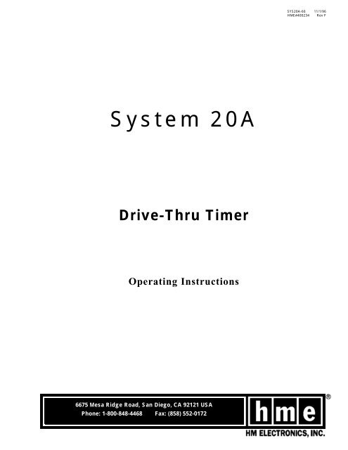
System <strong>20</strong>A<br />
Drive-Thru Timer<br />
Operating Instructions<br />
6675 Mesa Ridge Road, San Diego, CA 92121 USA<br />
Phone: 1-800-848-4468 Fax: (858) 552-0172
INTRODUCTION<br />
The <strong>HME</strong> System <strong>20</strong>A provides service time information that can be used to improve the efficiency<br />
of <strong>drive</strong>-<strong>thru</strong> service. It provides employees with immediate feedback on their speed of service,<br />
and provides management with a variety of printed reports that detail <strong>drive</strong>-<strong>thru</strong> activity.<br />
This <strong>manual</strong> is a guideline for setup and operation of the System <strong>20</strong>A. A list of accessories<br />
available for the <strong>timer</strong> <strong>system</strong> is provided. A simplified, step-by-step diagnostics guide is<br />
also included for routine troubleshooting.<br />
For System <strong>20</strong>A software version 2.0X<br />
NOTICE: In the event of an electrical power outage, such as from a lightning<br />
storm or power generator failure, if you experience problems with your <strong>HME</strong><br />
equipmant after the electricity comes on again, unplug the AC power adapters<br />
from their electrical outlets, then plug them back in.<br />
The <strong>HME</strong> logo is a registered trademark of HM Electronics, Inc.<br />
© Copyright HM Electronics, Inc. ---- November 1996
TABLE OF CONTENTS<br />
I. UNDERSTANDING THE SYSTEM <strong>20</strong>A TIMER . . . . . . . . . . . . . . . . . . . . . . . . . 1<br />
A. Definitions of Terms . . . . . . . . . . . . . . . . . . . . . . . . . . . . . . . . . . . . . . . . . . . 1<br />
B. Detection Points . . . . . . . . . . . . . . . . . . . . . . . . . . . . . . . . . . . . . . . . . . . . . 3<br />
C. Time Events . . . . . . . . . . . . . . . . . . . . . . . . . . . . . . . . . . . . . . . . . . . . . . . 4<br />
D. Explanation of Reports . . . . . . . . . . . . . . . . . . . . . . . . . . . . . . . . . . . . . . . . . 5<br />
E. Printer Paper . . . . . . . . . . . . . . . . . . . . . . . . . . . . . . . . . . . . . . . . . . . . . . . 9<br />
II. ACCESSING THE SYSTEM <strong>20</strong>A . . . . . . . . . . . . . . . . . . . . . . . . . . . . . . . . . 10<br />
III. SETTING UP THE SYSTEM <strong>20</strong>A . . . . . . . . . . . . . . . . . . . . . . . . . . . . . . . . . 12<br />
A. Keypad Lockout Code Setup . . . . . . . . . . . . . . . . . . . . . . . . . . . . . . . . . . . . 13<br />
B. System Setup . . . . . . . . . . . . . . . . . . . . . . . . . . . . . . . . . . . . . . . . . . . . . 14<br />
C. Printer Setup . . . . . . . . . . . . . . . . . . . . . . . . . . . . . . . . . . . . . . . . . . . . . . 17<br />
D. Display Contrast Setup . . . . . . . . . . . . . . . . . . . . . . . . . . . . . . . . . . . . . . . . 18<br />
E. Printout of the System Settings . . . . . . . . . . . . . . . . . . . . . . . . . . . . . . . . . . . 19<br />
F. Display Setup . . . . . . . . . . . . . . . . . . . . . . . . . . . . . . . . . . . . . . . . . . . . . <strong>20</strong><br />
G. Alert Tones Setup . . . . . . . . . . . . . . . . . . . . . . . . . . . . . . . . . . . . . . . . . . . 24<br />
H. Automatic Report Setup . . . . . . . . . . . . . . . . . . . . . . . . . . . . . . . . . . . . . . . 26<br />
I. Link Speakers Setup . . . . . . . . . . . . . . . . . . . . . . . . . . . . . . . . . . . . . . . . . 28<br />
IV. SETTING DAYPARTS AND TARGET TIMES . . . . . . . . . . . . . . . . . . . . . . . . . 29<br />
V. PRINTING ON-DEMAND REPORTS . . . . . . . . . . . . . . . . . . . . . . . . . . . . . . . 31<br />
A. Every-Car Report . . . . . . . . . . . . . . . . . . . . . . . . . . . . . . . . . . . . . . . . . . . 32<br />
B. Any-Hour Report . . . . . . . . . . . . . . . . . . . . . . . . . . . . . . . . . . . . . . . . . . . 33<br />
C. Any-Daypart Report . . . . . . . . . . . . . . . . . . . . . . . . . . . . . . . . . . . . . . . . . . 34<br />
D. Any-Day Report . . . . . . . . . . . . . . . . . . . . . . . . . . . . . . . . . . . . . . . . . . . . 35<br />
E. Any-Week Report . . . . . . . . . . . . . . . . . . . . . . . . . . . . . . . . . . . . . . . . . . . 35<br />
F. Any-Period Report . . . . . . . . . . . . . . . . . . . . . . . . . . . . . . . . . . . . . . . . . . 36<br />
G. Any-Month Report . . . . . . . . . . . . . . . . . . . . . . . . . . . . . . . . . . . . . . . . . . . 37<br />
H. Year-To-Date Report . . . . . . . . . . . . . . . . . . . . . . . . . . . . . . . . . . . . . . . . . 37<br />
I. Download Every-Car Report to PC . . . . . . . . . . . . . . . . . . . . . . . . . . . . . . . . . 38<br />
VI. ACCESSORIES . . . . . . . . . . . . . . . . . . . . . . . . . . . . . . . . . . . . . . . . . . . . 39<br />
FCC NOTICE . . . . . . . . . . . . . . . . . . . . . . . . . . . . . . . . . . . . . . . . . . . . . . . . . 40<br />
Appendix A - User Diagnostics . . . . . . . . . . . . . . . . . . . . . . . . . . . . . . . . . . . 41<br />
Appendix B - Installer Setup Changes . . . . . . . . . . . . . . . . . . . . . . . . . . . . . . 43<br />
Appendix C - PC Interface Setup . . . . . . . . . . . . . . . . . . . . . . . . . . . . . . . . . . 46<br />
Appendix D - Software Menu Reference for System <strong>20</strong>A . . . . . . . . . . . . . . . . . . 47
LIST OF FIGURES<br />
I. System <strong>20</strong>A Control Unit . . . . . . . . . . . . . . . . . . . . . . . . . . . . . . . 1<br />
2. Detection Points . . . . . . . . . . . . . . . . . . . . . . . . . . . . . . . . . . . . 3<br />
3. 24-Hour Time . . . . . . . . . . . . . . . . . . . . . . . . . . . . . . . . . . . . . . 4<br />
4. Sample Every-Car Report . . . . . . . . . . . . . . . . . . . . . . . . . . . . . . . 5<br />
5. Sample Any-Hour Report . . . . . . . . . . . . . . . . . . . . . . . . . . . . . . . 5<br />
6. Sample Any-Daypart Report . . . . . . . . . . . . . . . . . . . . . . . . . . . . . 6<br />
7. Sample Any-Day Report . . . . . . . . . . . . . . . . . . . . . . . . . . . . . . . 6<br />
8. Sample Any-Week Report . . . . . . . . . . . . . . . . . . . . . . . . . . . . . . 7<br />
9. Sample Any-Period Report . . . . . . . . . . . . . . . . . . . . . . . . . . . . . . 7<br />
10. Sample Any-Month Report . . . . . . . . . . . . . . . . . . . . . . . . . . . . . . 8<br />
11. Sample Year-To-Date Report . . . . . . . . . . . . . . . . . . . . . . . . . . . . . 8<br />
12. Loading Printer Paper . . . . . . . . . . . . . . . . . . . . . . . . . . . . . . . . . 9<br />
13. RS232 cable connectors . . . . . . . . . . . . . . . . . . . . . . . . . . . . . . 39<br />
14. Battery location inside System <strong>20</strong>A control unit . . . . . . . . . . . . . . . . . 42<br />
15. System <strong>20</strong>A battery . . . . . . . . . . . . . . . . . . . . . . . . . . . . . . . . . 42<br />
LIST OF TABLES<br />
I. Time Events . . . . . . . . . . . . . . . . . . . . . . . . . . . . . . . . . . . . . . 4<br />
2. Timer Configuration Numbers . . . . . . . . . . . . . . . . . . . . . . . . . . . 12<br />
3. System Settings Printout Numbers . . . . . . . . . . . . . . . . . . . . . . . . . 19<br />
4. Time Event Numbers . . . . . . . . . . . . . . . . . . . . . . . . . . . . . . . . 21
I. UNDERSTANDING THE SYSTEM <strong>20</strong>A TIMER<br />
A. Definitions of Terms<br />
Control display<br />
Data display<br />
Reset switch<br />
Printer<br />
Keypad<br />
Special function keys<br />
Figure 1. System <strong>20</strong>A Control Unit<br />
1. Equipment Definitions<br />
Control Unit - A white, wall-mounted unit with keypad, display panels and<br />
printer. It is the main component of the <strong>system</strong>.<br />
Control Unit Features:<br />
Control Display - The large display on the control unit, that shows the time<br />
a vehicle is present in various places in the <strong>drive</strong>-<strong>thru</strong> area. During times of<br />
no <strong>drive</strong>-<strong>thru</strong> activity, either all zeros, certain average times or the last<br />
vehicle time can be displayed.<br />
Data Display - A small display on the control unit, above the keypad, which<br />
shows the keypad entries when the <strong>system</strong> is being set up. The current date<br />
and time will appear on the upper line of this display during operation. The<br />
display indicates the presence of a vehicle at any of the four possible detection<br />
points with a V1, V2, V3 or V4 on the lower line of the display.<br />
Keypad - A pad of 19 touch-sensitive keys on the control unit. The keypad<br />
has numbered keys 0 through 9 and special function keys, to enter setup<br />
information into the <strong>system</strong> and to request printed reports.<br />
Printer - A built-in thermal printer, on the control unit, for printing reports.<br />
Reset Switch - A switch on the left side of the control unit, for resetting the<br />
displays<br />
Loop - An underground loop located at the menu board and/or service<br />
window. Vehicles stopping over this loop can be recorded by the <strong>system</strong>.<br />
Remote Display - A display unit located away from the control unit, such<br />
as in the cashier booth or manager’s office, showing the same type of<br />
information shown on the control display.<br />
1
2. Time Measurement Definitions<br />
Time Event - Any <strong>drive</strong>-<strong>thru</strong> event or series of events for which time is measured.<br />
Types of time events:<br />
Menu-Board Time - The time measured from a vehicle’s arrival at the menu<br />
board or speaker post to its departure from that point.<br />
Greeting-Delay Time - The time measured from a vehicle’s arrival at the menu<br />
board or speaker post to the time the order taker begins greeting the customer<br />
through the audio <strong>system</strong>.<br />
Queue Time - The time measured from a vehicle’s departure from the menu<br />
board or speaker post to its arrival at the service window, or to its arrival at<br />
the cashier window (Scenario 3 only).<br />
Cashier-Window Time - The time measured from a vehicle’s arrival at the<br />
cashier’s window to its departure from that point (Scenario 3 only).<br />
Booth-Queue Time - The time measured from a vehicle’s departure from the<br />
cashier’s window to its arrival at the service window (Scenario 3 only).<br />
Service-Window Time - The time measured from a vehicle’s arrival at the<br />
service window to its departure from that point.<br />
Total Booth Time - The time measured from a vehicle’s arrival at the cashier<br />
window to its departure from the service window (Scenario 3 only).<br />
Total Time - The time measured from a vehicle’s arrival at the menu board<br />
or speaker post to its departure from the service window.<br />
Wait-Area Time - (Scenario 3 only) The time measured from a vehicle’s arrival<br />
at the wait area to its departure from the wait area.<br />
Target Time - The ideal time (in seconds) to serve a customer. The target time<br />
can be entered into the <strong>system</strong> for comparison with actual service times.<br />
Ideally, 70% - 75% of your customers should be served within this time.<br />
Excess Time - Time beyond the maximum amount of time a vehicle should be<br />
at a detection point, based upon time of day and business volume.<br />
Dayparts - Up to 24 time periods that you enter into the <strong>system</strong> to break the<br />
day into service times. Dayparts are referred to by numbers 1 through 24. Each<br />
daypart number begins with whatever time you choose, and ends automatically<br />
as the next daypart begins. Some periods usually represented as dayparts are:<br />
breakfast, mid-morning, lunch, mid-afternoon, dinner, evening, late night hours<br />
and hours closed.<br />
Detection Point - A location at which a measurement of time is taken. The<br />
four detection points typically used with the System <strong>20</strong>A are the menu board,<br />
cashier window, service window and waiting area.<br />
24-Hour Time - Time based on a 24-hour clock, stated from 0000 to 2359 hours.<br />
See Figure 3 on page 4 for examples.<br />
Repeat Period - The time (in seconds) between repeating alerts that occur after<br />
a vehicle has been at a detection point beyond the excess time.<br />
2
B. Detection Points<br />
The following illustrations show the detection points where time measurements<br />
are made in each of the four <strong>drive</strong>-<strong>thru</strong> restaurant scenarios.<br />
Detection<br />
Point 1<br />
Service window<br />
Detection<br />
Point 1<br />
Service window<br />
Detection<br />
Point 2<br />
Menu board<br />
Scenario 1<br />
One Lane - One Detection Point<br />
Scenario 2<br />
One Lane - Two Detection Points<br />
Detection<br />
Point 3<br />
Cashier window<br />
Detection<br />
Point 2<br />
Menu board<br />
Detection<br />
Point 2<br />
Lane 1<br />
Menu board<br />
Detection<br />
Point 4<br />
Lane 2<br />
Menu board<br />
Detection<br />
Point 4<br />
Waiting area<br />
Detection<br />
Point 1<br />
Service window<br />
Detection<br />
Point 1<br />
Lane 1<br />
Service Window<br />
Detection<br />
Point 3<br />
Lane 2<br />
Service Window<br />
Scenario 3<br />
One Lane - Four Detection Points<br />
Scenario 4<br />
Two Lanes - Four Detection Points<br />
Figure 2. Detection Points<br />
3
C. Time Events<br />
Scenario 1: One Lane -- One Detection Point Event 1<br />
Scenario 2: One Lane -- Two Detection Points Events 1--5<br />
Scenario 3: One Lane -- Four Detection Points Events 1--9<br />
Scenario 4: Two Lanes -- Four Detection Points Events 1--5, 10--14<br />
Event: From: Until:<br />
* 1 Service-Window Time arrival at service window departure from service window<br />
2 Greeting-Delay Time arrival at menu board greeting begins<br />
L<br />
a<br />
n<br />
e<br />
1<br />
3 Menu-Board Time arrival at menu board departure from menu board<br />
4 Queue Time departure from menu board<br />
arrival at service window<br />
(or cashier window<br />
in Scenario 3)<br />
* 5 Total Time arrival at menu board departure from service window<br />
* 6 Cashier-Window Time arrival at cashier window departure from cashier window<br />
7 Booth-Queue Time departure from cashier window arrival at service window<br />
8 Total Booth Time arrival at cashier window departure from service window<br />
9 Wait-Area Time arrival at wait area departure from wait area<br />
L<br />
a<br />
n<br />
e<br />
2<br />
* 10 Service-Window Time arrival at service window departure from service window<br />
11 Greeting-Delay Time arrival at menu board greeting begins<br />
12 Menu-Board Time arrival at menu board departure from menu board<br />
13 Queue Time departure from menu board arrival at service window<br />
* 14 Total Time arrival at menu board departure from service window<br />
Table 1. Time Events<br />
* Most commonly used time events<br />
Use 24-hour time.<br />
All time entries must be made in 24-hour time.<br />
Instead of 12 hours in the AM and 12 hours in the PM, the 24-hour clock has 24<br />
continuous hours, from 00:00 to 23:59 hrs. The first two numbers tell the hour, and<br />
the last two numbers tell the minutes past the hour.<br />
07:23<br />
AM<br />
12<br />
11 1<br />
10 2<br />
AM PM<br />
12<br />
11 1<br />
10 2<br />
PM<br />
13:50<br />
hours<br />
minutes<br />
9 3<br />
8 4<br />
9 3<br />
8 4<br />
hours<br />
minutes<br />
7 5<br />
6<br />
7 5<br />
6<br />
Figure 3.<br />
24-Hour Time<br />
7:23 AM = 07:23 hrs<br />
This clock shows 7:23 AM, which is<br />
the same as 07:23 hrs in 24-hour time.<br />
1:50 PM = 13:50 hrs<br />
This clock shows 1:50 PM, which is<br />
the same as 13:50 hrs in 24-hour time.<br />
4
D. Explanation of Reports<br />
The <strong>system</strong> prints eight reports of <strong>drive</strong>-<strong>thru</strong> activity: 1. Every-Car Report,<br />
2. Any-Hour Report, 3. Any-Daypart Report, 4. Any-Day Report, 5. Any-Week<br />
Report, 6. Any-Period Report, 7. Any-Month Report and 8. Year-To-Date Report.<br />
Reports 1 through 8 can be printed "on demand," when commanded from the<br />
keypad. Reports 1 through 4 can also be set to print automatically. (See page 19,<br />
section III, E, for setting automatic printing of reports.) When a report is set to print<br />
automatically, it will always print at the designated times, every day, unless you change<br />
the automatic-print setting.<br />
1. Every-Car Report<br />
If selected to print "on demand," the Every-<br />
Car Report shows every customer served<br />
between the selected start and end times. If<br />
selected to print automatically, the report<br />
will print after every two customers.<br />
It shows the time of day, the Service-<br />
Window Time and total time in seconds<br />
for each customer. Times can be shown<br />
for up to the last 49,000 customers.<br />
When two lanes are used, the left column<br />
is for lane 1 and the right is for lane 2.<br />
Scenario 3 reports will also show Cashier-<br />
Window Time.<br />
2. Any-Hour Report<br />
If selected to print "on demand," the Any-<br />
Hour Report shows <strong>drive</strong>-<strong>thru</strong> activity for<br />
any previous, one-hour period, ending<br />
with the selected hour. If selected to print<br />
automatically, the report will print after<br />
every hour.<br />
It shows the day, date and time of day,<br />
how many customers have been served<br />
in the hour, the total number of seconds<br />
the customer waited at the <strong>drive</strong>-<strong>thru</strong> window<br />
and the average service time per<br />
customer. It also shows how many customers<br />
were served under target time,<br />
over target time, over excess time and the<br />
three longest times.<br />
NOTE: The hour selected must have<br />
ended, or this report will not print.<br />
Sun. 06/11/95 18:05 Store ID: 031891<br />
----------------------------------<br />
EVERY CAR REPORT<br />
----------------<br />
Sun. 06/11/95<br />
06:00 Until 18:00<br />
11:40 / 38 / 136 11:40 / 26 / 102<br />
11:41 / 58 / 168 11:41 / 47 / 181<br />
-------------End of Report------------<br />
Time of Day<br />
(in 24 hour time)<br />
Service Window<br />
Time<br />
(in seconds)<br />
Figure 4. Sample Every-Car Report<br />
NOTE: Reports shown are examples only.<br />
Actual reports may vary with<br />
different <strong>drive</strong>-<strong>thru</strong> scenarios.<br />
Sun. 06/11/95 18:05 Store ID: 031891<br />
----------------------------------<br />
HOUR REPORT<br />
-----------<br />
Sun. 06/11/95<br />
17:00 Until 18:00<br />
SERVICE WINDOW<br />
--------------<br />
# CARS SERVED = 36<br />
TOTAL SECONDS = 1387<br />
AVERAGE TIME = 38.53<br />
# CARS UNDER TARGET = 34 94%<br />
# CARS OVER TARGET = 2 6%<br />
# CARS OVER EXCESS = 0 0%<br />
LONGEST TIMES =<br />
17:11 / 063 17:35 / 060 17:50 / 062<br />
SUMMARY HOUR REPORT<br />
------------------<br />
TOTAL CARS = 36<br />
TOTAL PULLOUTS = 0<br />
AVE. MENU TIME = 41.08<br />
AVE. GREET DELAY TIME = 4.08<br />
AVE. QUEUE TIME = 9.14<br />
AVE. WINDOW TIME = 38.53<br />
AVE. TOTAL TIME = 88.75<br />
-------------End of Report------------<br />
Total Time<br />
(in seconds)<br />
Figure 5. Sample Any-Hour Report<br />
5
3. Any-Daypart Report<br />
If selected to print "on demand," the Any-<br />
Daypart Report corresponds to a daypart<br />
number that you have selected. If selected<br />
to print automatically, the daypart report will<br />
print after each daypart has ended.<br />
It shows the day, date and times of day<br />
the daypart begins and ends. This report<br />
records the total number of customers<br />
served, total number of seconds and average<br />
service time per customer in that<br />
daypart. It also shows how many customers<br />
were served under the target<br />
time, over the target time and over the<br />
excess times (based upon target and<br />
excess times selected for this daypart).<br />
NOTE: The daypart selected must have<br />
ended, or this report will not print.<br />
Sun. 06/11/95 18:05 Store ID: 031891<br />
----------------------------------<br />
DAYPART CAR REPORT<br />
-----------------<br />
Sun. 06/11/95 -- Sun. 06/11/95<br />
16:00 Until 23:00<br />
SERVICE WINDOW<br />
--------------<br />
# CARS SERVED = 251<br />
TOTAL SECONDS = 9988<br />
AVERAGE TIME = 39.79<br />
# CARS UNDER TARGET = 236 94%<br />
# CARS OVER TARGET = 15 6%<br />
# CARS OVER EXCESS = 0 0%<br />
SUMMARY DAYPART REPORT<br />
---------------------<br />
TOTAL CARS = 251<br />
TOTAL PULLOUTS = 0<br />
AVE. MENU TIME = 41.29<br />
AVE. GREET DELAY TIME = 4.29<br />
AVE. QUEUE TIME = 9.13<br />
AVE. WINDOW TIME = 39.79<br />
AVE. TOTAL TIME = 90.21<br />
------------ End of Report ------------<br />
Figure 6. Sample Any-Daypart Report<br />
4. Any-Day Report<br />
If selected to print "on demand," the Any-<br />
Day Report shows information on the total<br />
number of customers served during the<br />
selected 24 hours. If selected to print<br />
automatically, this report will print at midnight<br />
(00:00) for the previous day.<br />
It includes average service times, and the<br />
number of customers served under and<br />
over target times, and over excess<br />
times. These totals take into consideration<br />
the changes in target and excess<br />
times for various periods throughout the<br />
day. For example, the sample report to<br />
the right shows that 94% of the customers<br />
were served under the target time<br />
at the service window. This may mean<br />
that customers were served under 30 seconds<br />
during lunch and under 90 seconds<br />
in the mid-afternoon.<br />
NOTE: The day selected must have<br />
ended, or this report will not print.<br />
Sun. 06/11/95 18:05 Store ID: 031891<br />
----------------------------------<br />
DAY REPORT<br />
----------<br />
Sun. 06/11/95<br />
00:00:00 Until 23:59:59<br />
SERVICE WINDOW<br />
--------------<br />
# CARS SERVED = 611<br />
TOTAL SECONDS = 24505<br />
AVERAGE TIME = 40.11<br />
# CARS UNDER TARGET = 572 94%<br />
# CARS OVER TARGET = 39 6%<br />
# CARS OVER EXCESS = 0 0%<br />
SUMMARY DAY REPORT<br />
-----------------<br />
TOTAL CARS = 611<br />
TOTAL PULLOUTS = 0<br />
AVE. MENU TIME = 40.60<br />
AVE. GREET DELAY TIME = 3.96<br />
AVE. QUEUE TIME = 9.13<br />
AVE. WINDOW TIME = 40.11<br />
AVE. TOTAL TIME = 89.83<br />
------------End of Report------------<br />
Figure 7. Sample Any-Day Report<br />
6
5. Any-Week Report<br />
The Any-Week Report shows information<br />
on the total number of customers served<br />
during any seven-day period, beginning<br />
with the day selected. It shows the days,<br />
dates and times of day the week begins<br />
and ends.<br />
When selecting this report, an option is<br />
given to also print a report for each day<br />
of the week selected.<br />
NOTE: The selected seven-day period<br />
must have ended, or this report<br />
will not print.<br />
This report gives a breakdown of the total<br />
number of customers served, total number<br />
of seconds and average service time<br />
per customer in that seven-day period. It<br />
also shows how many customers were<br />
served under the target time, over the<br />
target time and over the excess times.<br />
Sun. 06/11/95 18:05 Store ID: 031891<br />
----------------------------------<br />
WEEK REPORT<br />
-----------<br />
Sun. 06/04/95 10:00<br />
Through Mon. 06/12/95 01:59<br />
SERVICE WINDOW<br />
--------------<br />
# CARS SERVED = 251<br />
TOTAL SECONDS = 9988<br />
AVERAGE TIME = 39.79<br />
# CARS UNDER TARGET = 236 94%<br />
# CARS OVER TARGET = 15 6%<br />
# CARS OVER EXCESS = 0 0%<br />
SUMMARY WEEK REPORT<br />
------------------<br />
TOTAL CARS = 251<br />
TOTAL PULLOUTS = 0<br />
AVE. MENU TIME = 41.29<br />
AVE. GREET DELAY TIME = 4.29<br />
AVE. QUEUE TIME = 9.13<br />
AVE. WINDOW TIME = 39.79<br />
AVE. TOTAL TIME = 90.21<br />
------------End of Report------------<br />
Figure 8. Sample Any-Week Report<br />
6. Any-Period Report<br />
The Any-Period Report shows information<br />
on the total number of customers served<br />
during any period, beginning with the day<br />
selected. It shows the days, dates and<br />
times of day the period begins and ends.<br />
The number of days in a report period<br />
was selected during the <strong>system</strong> setup.<br />
To change the number of days in a period,<br />
refer to page 14, section III, B, 2.<br />
When selecting this report, an option is<br />
given to also print a separate report for<br />
each week in the selected period. Only<br />
complete weeks will print.<br />
NOTE: The selected period must have<br />
ended, or this report will not print.<br />
This report gives a breakdown of the total<br />
number of customers served, total number<br />
of seconds and average service time<br />
per customer in the selected period. It<br />
also shows how many customers were<br />
served under the target time, over the<br />
target time and over the excess times.<br />
Sun. 06/11/95 18:05 Store ID: 031891<br />
----------------------------------<br />
PERIOD REPORT<br />
-------------<br />
Fri. 06/09/95 10:00<br />
Through Mon. 06/12/95 01:59<br />
SERVICE WINDOW<br />
--------------<br />
# CARS SERVED = 611<br />
TOTAL SECONDS = 24505<br />
AVERAGE TIME = 40.11<br />
# CARS UNDER TARGET = 572 94%<br />
# CARS OVER TARGET = 39 6%<br />
# CARS OVER EXCESS = 0 0%<br />
SUMMARY PERIOD REPORT<br />
--------------------<br />
TOTAL CARS = 611<br />
TOTAL PULLOUTS = 0<br />
AVE. MENU TIME = 40.59<br />
AVE. GREET DELAY TIME = 3.96<br />
AVE. QUEUE TIME = 9.13<br />
AVE. WINDOW TIME = 40.11<br />
AVE. TOTAL TIME = 89.83<br />
............End of Report............<br />
Figure 9. Sample Any-Period Report<br />
7
7. Any-Month Report<br />
The Any-Month Report provides data on<br />
the total number of customers served during<br />
the selected month. It shows the<br />
days, dates and times of day the month<br />
begins and ends.<br />
This report gives a breakdown of the total<br />
number of customers served, total number<br />
of seconds and average service time<br />
per customer in that month. It also shows<br />
how many customers were served under<br />
target time, over target time and over<br />
excess times.<br />
Sun. 06/11/95 18:05 Store ID: 031891<br />
----------------------------------<br />
MONTH REPORT<br />
-----------<br />
Mon. 05/01/95 10:00<br />
Through Thu. 06/01/95 01:59<br />
SERVICE WINDOW<br />
-------------<br />
# CARS SERVED = 251<br />
TOTAL SECONDS = 9988<br />
AVERAGE TIME = 39.79<br />
# CARS UNDER TARGET = 236 94%<br />
# CARS OVER TARGET = 15 6%<br />
# CARS OVER EXCESS = 0 0%<br />
SUMMARY MONTH REPORT<br />
-------------------<br />
TOTAL CARS = 251<br />
TOTAL PULLOUTS = 0<br />
AVE. MENU TIME = 41.29<br />
AVE. GREET DELAY TIME = 4.29<br />
AVE. QUEUE TIME = 9.13<br />
AVE. WINDOW TIME = 39.79<br />
AVE. TOTAL TIME = 90.21<br />
............End of Report............<br />
Figure 10. Sample Any-Month Report<br />
8. Year-To-Date Report<br />
The Year-To-Date Report provides data on<br />
the total number of customers served from<br />
the beginning of the fiscal year through<br />
the last full day. It shows the days, dates<br />
and times of day the report begins and<br />
ends.<br />
NOTE: If your <strong>timer</strong> <strong>system</strong> was setup<br />
after the first day of the current<br />
fiscal year, this report will include<br />
data from the <strong>system</strong> setup date<br />
through the last full day (yesterday).<br />
This report gives a breakdown of the total<br />
number of customers served, total number<br />
of seconds and average service time<br />
per customer in the current fiscal year. It<br />
also shows how many customers were<br />
served under target time, over target time<br />
and over excess times.<br />
Sun. 06/11/95 18:05 Store ID: 031891<br />
----------------------------------<br />
YEAR-TO-DATE REPORT<br />
-----------<br />
Sun. 01/01/95 10:00<br />
Through Sun. 06/11/95 01:59<br />
SERVICE WINDOW<br />
--------------<br />
# CARS SERVED = 611<br />
TOTAL SECONDS = 24505<br />
AVERAGE TIME = 40.11<br />
# CARS UNDER TARGET = 572 94%<br />
# CARS OVER TARGET = 39 6%<br />
# CARS OVER EXCESS = 0 0%<br />
SUMMARY YEAR-TO-DATE REPORT<br />
--------------------------<br />
TOTAL CARS = 611<br />
TOTAL PULLOUTS = 0<br />
AVE. MENU TIME = 40.59<br />
AVE. GREET DELAY TIME = 3.96<br />
AVE. QUEUE TIME = 9.13<br />
AVE. WINDOW TIME = 40.11<br />
AVE. TOTAL TIME = 89.83<br />
............End of Report............<br />
Figure 11. Sample Year-To-Date Report<br />
8
E. Printer Paper<br />
A special type of thermal paper is used for the System <strong>20</strong>A printer.<br />
To order paper, refer to ordering details in section VI, page 39 of this <strong>manual</strong>.<br />
TO LOAD PRINTER PAPER<br />
❑ Remove the tape from the paper roll and<br />
unroll 2 inches of paper. Be certain there is<br />
a straight edge on the paper.<br />
❑ Hold the roll in your left hand, as shown on<br />
figure 12.<br />
❑ Hold the paper against the blue plastic and<br />
slide it down until it enters the paper-feed<br />
slot.<br />
❑ Move the paper slightly left and right, and<br />
push it as far as possible into the slot.<br />
❑ Hold the paper in place.<br />
❑ Push the PAPER FEED key. Paper should<br />
begin to be pulled into the printer.<br />
❑ Continue pushing the PAPER FEED key until<br />
the paper appears at the paper-cutter slot<br />
(minimum of three times).<br />
Figure 12.<br />
Loading Printer Paper<br />
❑ If paper is not being pulled into the printer,<br />
it is not properly aligned, or was not far<br />
enough into the printer.<br />
❑ If the printer malfunctions, wait 30 seconds.<br />
Then press the ESC key repeatedly until the<br />
date and time appear on the data display,<br />
then press the PAPER FEED key. Pull on the<br />
paper to be certain it feeds freely.<br />
9
II. ACCESSING THE SYSTEM <strong>20</strong>A<br />
After a <strong>system</strong> has been installed and the power supply has been plugged in, the<br />
<strong>system</strong> will be in operation. There is no ON/OFF switch on the control unit.<br />
To control access to various functions, the System <strong>20</strong>A provides different levels of<br />
security, using codes which must be entered through the keypad. The lowest level<br />
of access is available when the user passcode is entered. The user passcode level<br />
allows reports to be generated, but does not allow <strong>system</strong> settings to be changed.<br />
The next level of access is available when the lockout code is entered. The lockout<br />
code level allows <strong>system</strong> settings to be changed, and reports to be generated. If<br />
the <strong>system</strong> is set up with a lockout code and a blank user passcode, anyone can<br />
generate reports but only a person who knows the lockout code can change the<br />
<strong>system</strong> settings. A new <strong>system</strong> does not have a lockout code or user pass code.<br />
Refer to page 13 for instructions on setting or changing either or both of these<br />
codes. Each code can have up to seven digits.<br />
When the System <strong>20</strong>A is first installed and plugged in, or when it has been reset by<br />
removal of the battery, the first two messages shown on page 11 will appear on the<br />
data display. When the first message appears, enter a date (mm/dd/yy) at least one<br />
month prior to the current date, and press the ENTER key. Using this earlier date is<br />
necessary for the <strong>system</strong> to correctly set up the data base to properly handle any<br />
report request. The correct current date should be entered later using the <strong>system</strong><br />
setup function shown on page 14. Some companies insist that all their stores use<br />
the same date for this entry, so be certain of such customer requirements before<br />
entering a date.<br />
If requested, enter the current time and press the ENTER key. If the date and time<br />
information was entered by the <strong>system</strong> installer, the two displays requesting it will not<br />
appear. Instead, the date and time will appear on the display as shown in the third<br />
message on page 11. If this is the case, proceed with Step 1.<br />
10
Step 1<br />
If a lockout code or user passcode has<br />
already been set up, enter it now to<br />
access the <strong>system</strong>. When the key for the<br />
first digit is pressed, the display will<br />
change to show the "Lockout code:" message.<br />
As each number key is pressed, it<br />
will appear in the data display, like the<br />
example "641" code shown to the right.<br />
When all the digits of the code have been<br />
entered, press the ENTER key.<br />
If no lockout code or user passcode has<br />
been set up, simply press the ENTER key<br />
to access the <strong>system</strong>. If you are not certain<br />
whether or not a code has been set<br />
in the memory, press the ENTER key. The<br />
appearance of a WARNING message indicates<br />
that a code is set.<br />
If an incorrect code is entered, or if none is<br />
entered when one is required, a WARNING<br />
message like the one shown to the right<br />
will appear on the data display. After a<br />
few seconds, the display will return to the<br />
lockout code message and wait for entry<br />
of the proper code.<br />
NOTE: A lockout code will allow <strong>system</strong><br />
setups to be made. A user passcode<br />
will only allow reports to be printed.<br />
Setting Up Data Base<br />
Enter Date: 01/01/93<br />
Setting Up Data Base<br />
Enter Time: 00:00:00<br />
Ø6/Ø7/95 Ø6:Ø3:22<br />
> <<br />
ENTER<br />
right<br />
code<br />
no<br />
Is a<br />
code set?<br />
ENTER<br />
yes<br />
Ø6/Ø7/95 16:Ø3:2Ø<br />
Lockout code: 641<br />
wrong<br />
code<br />
WARNING 4ØØ2<br />
illegal user<br />
Step 2<br />
When the correct lockout code has<br />
been entered, the display shown to the<br />
right will appear.<br />
Ø6/Ø7/95 Ø6:Ø4:08<br />
Enter command or ESC<br />
ESC<br />
To exit this display and return to the lockout<br />
condition, press the ESC key.<br />
To enter the Setup, Daypart or Report mode,<br />
press the SETUP, DAYPART or REPORT command<br />
key and refer to the page noted. To<br />
change any of the Installer Setup informa-<br />
SETUP<br />
go to<br />
page 12<br />
command keys<br />
DAY<br />
PART<br />
go to<br />
page 29<br />
REPORT<br />
go to<br />
page 31<br />
*<br />
SETUP<br />
go to<br />
page 43<br />
tion, press the<br />
*<br />
key, then press the<br />
SETUP key and refer to the page noted.<br />
11
III. SETTING UP THE SYSTEM <strong>20</strong>A<br />
The basic System <strong>20</strong>A setups were done at the factory or by the installer, and should NOT<br />
need to be done again. However, if it becomes necessary to reset any of the basic<br />
<strong>system</strong> settings, follow the instructions in this section.<br />
Step 1:<br />
Complete the instructions for lockout code entry on page 11 before<br />
going any further. If you have done this go to Step 2.<br />
Step 2: action result<br />
To enter the Timer Configuration mode,<br />
press the SETUP key .<br />
WARNING: If no keys are pressed within 5<br />
minutes, the <strong>timer</strong> will return to lockout.<br />
Timer Configuration<br />
(1-10) or Ø=Done: Ø<br />
NOTE: If you need to exit Timer Configuration<br />
and return to the Enter Command<br />
display, press the ESC key.<br />
Step 3: action result<br />
To enter any of the setups shown in<br />
Table 2 below, press the number keys to<br />
enter a number from Ø to 10.<br />
Setup Printer, Ø=None<br />
1=Intrnal, 2=Remote:1<br />
Example entry: Ø<br />
To complete this entry and go to the next<br />
step, press the ENTER key, then go to<br />
the page shown in Table 2 below.<br />
The various Timer Configurations are<br />
explained on the pages shown below.<br />
1 = Printer Setup (page 17)<br />
2 = System Setup (pages 14)<br />
3 = Display Setup (pages <strong>20</strong>)<br />
4 = Alert Tones Setup (pages 24)<br />
5 = Speaker Linking (page 28)<br />
6 = Keypad Lockout Code Setup (page 13)<br />
7 = Automatic Report Setup (page 26)<br />
8 = Printout of the System Settings (page 19)<br />
9 = Display Contrast Setup (page 18)<br />
10 = User Diagnostics (page 41)<br />
Table 2. Timer Configuration Numbers<br />
12
A. Keypad Lockout Code Setup<br />
To prevent unauthorized access to the System <strong>20</strong>A, you can establish<br />
a keypad lockout code and a user passcode, each of which can be up to 7-digits.<br />
Follow the instructions below.<br />
Step 1: action result<br />
Complete the instructions on page 11.<br />
Press the SETUP, 6 and ENTER keys<br />
to get the display to the right.<br />
Change code:Ø=Done<br />
1=Lockout, 2=User:Ø<br />
NOTE: To exit the Keypad Lockout mode<br />
and return to the Timer Configuration<br />
display, press the ESC key. (Any<br />
changes already made will be saved.)<br />
Step 2: action result<br />
To enter a new keypad lockout code, or<br />
change an existing code, press 1 then<br />
ENTER.<br />
or<br />
To enter a new user passcode, or change<br />
an existing code, press 2 then ENTER.<br />
If you do not want to enter a new keypad<br />
lockout code or user passcode, press<br />
the ENTER key to return to the Timer<br />
Configuration display.<br />
Keypad LockOut<br />
Lockout code:<br />
or<br />
User Access<br />
Usr Passcode:<br />
NOTE: The lockout code and user passcode<br />
can be set to two different numbers.<br />
They can both be left blank, or the user<br />
passcode alone can be left blank.<br />
Step 3: action result<br />
Use the number keys to enter a new code<br />
of up to 7-digits, then press ENTER.<br />
Example entry: 2457<br />
NOTE: If a lockout code was already<br />
entered and you no longer want<br />
a lockout code, press CLR then<br />
press ENTER.<br />
Timer Configuration<br />
(1--1Ø) or Ø=Done : 6<br />
This completes the Keypad Lockout Setup. Other Timer Configuration settings<br />
can be selected by pressing any of the number keys shown on Table 2, page<br />
12. Press the ESC key to return to the Enter Command display on page 11.<br />
13
B. System Setup<br />
The System Setup mode allows entry of basic information such as dates and times,<br />
used by the System <strong>20</strong>A to generate various reports.<br />
CAUTION: Be certain dates entered are correct, or valuable data may be lost.<br />
Step 1: action result<br />
Complete the instructions on page 11.<br />
Press the SETUP, 2 and ENTER keys<br />
to get the display to the right.<br />
System Setup<br />
Enter Date: Ø6/Ø7/95<br />
NOTE: If you need to exit the System Setup<br />
mode and return to the Timer Configuration<br />
display, press the ESC key. (Any<br />
changes already made will be saved.)<br />
Step 2: action result<br />
If the date is correct, press the ENTER key<br />
to go to the next display.<br />
To change the date, press the number keys<br />
to enter the current date, then press ENTER.<br />
NOTE: The date cannot be set back to a<br />
previous date.<br />
Example entry : 06/07/95<br />
System Setup<br />
Enter Time: Ø6:29:15<br />
Step 3: action result<br />
If the time is correct, press the ENTER key<br />
to go to the next display.<br />
To change the time, press the number<br />
keys to enter the current time (in 24-hour<br />
time), then press ENTER.<br />
Example entry : 06:29:15<br />
System Setup<br />
Store ID # :<br />
NOTE: Always use 24-hour time.<br />
For example, a time such as 15:04:08<br />
would be the same as 3:04:08 P.M.<br />
Refer to page 2 for explanation of<br />
24-hour time.<br />
If the date is set forward by more than a few<br />
days, the <strong>system</strong> will spend several seconds<br />
processing the date/time change before<br />
the store ID display is shown.<br />
14
Step 4: action result<br />
To enter the store ID number, press the<br />
number keys, then press ENTER.<br />
Example entry : 247<br />
System Setup<br />
Fiscal Date:Ø1/Ø1/95<br />
Step 5: entry result<br />
To enter the fiscal date indicating the<br />
beginning of the store’s fiscal year, press<br />
the number keys for month/day/year, then<br />
press ENTER.<br />
Example entry : 01/01/95<br />
NOTE: If fiscal date does not apply, enter<br />
beginning of current year.<br />
System Setup<br />
Opening Time >1Ø:ØØ<br />
Step 6: entry result<br />
NOTE: In 24 hour store <strong>operations</strong>, to<br />
avoid combining the current day’s data<br />
with the following day’s data, enter the<br />
opening time as 00:00 and the closing<br />
time as 23:59. Also, set the first daypart<br />
to 00:00. Refer to page 29.<br />
Entering a closing time that is before<br />
the opening time tells the System <strong>20</strong>A<br />
that the store day extends past midnight<br />
(00:00). Information collected<br />
after 00:00 is attached to the following<br />
calendar day, and combined with the<br />
next day’s data.<br />
To enter the store Opening Time, press<br />
the number keys, then press ENTER.<br />
System Setup<br />
Closing Time >Ø2:ØØ<br />
Example entry : 06:00<br />
NOTE: Use 24-hour time.<br />
Step 7: entry result<br />
To enter the store Closing Time, press the<br />
number keys, then press ENTER.<br />
System Setup<br />
Period Days 14min: 14<br />
Example entry : 23:00<br />
15
Step 8: entry result<br />
To enter the number of reporting Period<br />
Days in the store’s standard reporting<br />
period, press the number keys, then<br />
press ENTER.<br />
Delete Time Ø-3sec<br />
Enter 1=Yes, Ø=No: Ø<br />
NOTE: These periods must be a<br />
minimum of 14 days and a<br />
maximum of 365 days, and are<br />
typically either 14, 21 or 28 days.<br />
Example entry : 28<br />
Step 9: entry result<br />
To delete car entries with times of 3 seconds<br />
or less, press key 1. Otherwise press<br />
the Ø key.<br />
Timer Configuration<br />
(1--1Ø) or Ø=Done : 2<br />
To return to the Timer Configuration<br />
display, press the ENTER key.<br />
This completes the System Setup. Other Timer Configuration settings can be<br />
selected by pressing any of the number keys shown on Table 2, page 12. Press<br />
the ESC key to return to the Enter Command display on page 11.<br />
16
C. Printer Setup<br />
The Printer Setup mode allows the System <strong>20</strong>A to be set up for use with its internal<br />
printer, an external, serial printer or no printer at all.<br />
NOTE: An external, serial printer can be purchased as an accessory to the System<br />
<strong>20</strong>A. For ordering information, see page 39. The printer cable connects to a 9-pin,<br />
RS232 connector on the top of the System <strong>20</strong>A control unit.<br />
Step 1: action result<br />
Complete the instructions on page 11.<br />
Press the SETUP, 1 and ENTER keys<br />
to get the display to the right.<br />
Setup Printer, Ø= None<br />
1=Intrnal, 2=Remote:1<br />
NOTE: If you need to exit the Printer Setup<br />
mode and return to the Timer Configuration<br />
display, press the ESC key.<br />
Step 2: entry result<br />
Press key 1 or 2 to indicate whether an<br />
internal or remote (external) printer will be<br />
used for System <strong>20</strong>A printouts. Press the<br />
Ø key if no printer will be used. Then press<br />
ENTER to return to the Timer Configuration<br />
display.<br />
Timer Configuration<br />
(1--1Ø) or Ø=Done : 1<br />
This completes the Printer Setup. Other Timer Configuration settings can be<br />
selected by pressing any of the number keys shown on Table 2, page 12. Press<br />
the ESC key to return to the Enter Command display on page 11.<br />
17
D. Display Contrast Setup<br />
The Display Contrast Setup mode allows you to adjust the contrast of the data<br />
display (LCD).<br />
Step 1: action result<br />
Complete the instructions on page 11.<br />
Press the SETUP, 9 and ENTER keys<br />
to get the display to the right.<br />
LCD Contrast (Ø--9)<br />
or [=Brighter, #=Dim<br />
Step 2: entry result<br />
Press the number keys Ø--9 for coarse<br />
changes (Ø=lightest, 9=darkest), or the<br />
*<br />
or # key for fine contrast changes.<br />
Repeat pressing the key until the desired<br />
contrast is reached.<br />
Timer Configuration<br />
(1--1Ø) or Ø=Done : 9<br />
ESC cancels change and restores<br />
previous setting.<br />
Press ENTER to accept change and<br />
return to the Timer Configuration display.<br />
NOTE: Be careful not to make the display<br />
too light, or you may not see it.<br />
This completes the Display Contrast Setup. Other Timer Configuration settings<br />
can be selected by pressing any of the number keys shown on Table 2,<br />
page 12. Press the ESC key to return to the Enter Command display on page 11.<br />
18
E. Printout of the System Settings<br />
To obtain a printout of the System <strong>20</strong>A setups you have made, for future<br />
reference, follow the instructions below. Always run printouts of the <strong>system</strong><br />
settings report before and after any changes are made to the <strong>system</strong> setup.<br />
Compare the "before" and "after" reports to verify that the desired changes were<br />
done correctly. These printouts are also helpful when calling <strong>HME</strong> for assistance.<br />
Step 1: action result<br />
Complete the instructions on page 11.<br />
Press the SETUP, 8 and ENTER keys<br />
to get the display to the right.<br />
Print Setups Ø=Done<br />
(1--7) or 8 for all:Ø<br />
NOTE: If you need to exit the Print Setups<br />
mode and return to the Timer Configuration<br />
display, press the ESC key.<br />
Step 2: entry result<br />
To select a specific setup printout,<br />
press any key, 1 through 7. Refer to the<br />
table below. To print all <strong>system</strong> setups,<br />
press the 8 key.<br />
Settings Report<br />
Please wait . . .<br />
1 = Daypart Settings Report<br />
2 = System Settings Report<br />
3 = Display Settings Report<br />
4 = Alert Settings Report<br />
5 = Speaker Links Settings Report<br />
6 = Installer Settings Report<br />
7 = Automatic Reports Settings Report<br />
8 = Print All Settings Reports<br />
Table 3. System Settings Printout Numbers<br />
Print Setups Ø=Done<br />
(1--7) or 8 for all:Ø<br />
Step 3: entry result<br />
If you do not want another printout,<br />
press ESC to return to the Timer Configuration<br />
display.<br />
Timer Configuration<br />
(1--1Ø) or Ø=Done : 8<br />
This completes the printing of <strong>system</strong> settings. Other Timer Configuration<br />
settings can be selected by pressing any of the number keys shown on Table 2,<br />
page 12. Press the ESC key to return to the Enter Command display on page 11.<br />
19
F. Display Setup<br />
The display setup is for selecting the kind of data to be shown on the control unit<br />
display and any remote display units. The control unit is always designated<br />
display number 1. Each remote display unit was assigned a number, 2<br />
through 4, by the System <strong>20</strong>A installer at the time of installation. Only 3<br />
remote units can be used with the System <strong>20</strong>A.<br />
Step 1: action result<br />
Complete the instructions on page 11.<br />
Press the SETUP, 3 and ENTER keys<br />
to get the display to the right.<br />
DisplayConfig:Ø=Done<br />
Display # (1--4) :Ø<br />
NOTE: If you need to exit the Display<br />
Setup mode and return to the<br />
Timer Configuration display, press<br />
the ESC key.<br />
Step 2: action result<br />
To enter the number of the control display<br />
(1) or remote display (2--4) now being programmed,<br />
press the respective number key,<br />
then press ENTER.<br />
Example entry : 2<br />
Display 1 Setup<br />
Time event (1--9):1<br />
Scenario 2 has 5 timing events.<br />
The number of timing events<br />
varies with other scenarios.<br />
<strong>20</strong>
Step 3: action result<br />
To enter the time event that will be displayed<br />
on the selected display, press<br />
one of the following number keys, then<br />
press ENTER. (See page 4 for detailed<br />
explanation of time events.)<br />
Flash At Target Time?<br />
Enter 1= Yes, Ø= No:1<br />
L<br />
a<br />
n<br />
e<br />
1<br />
L<br />
a<br />
n<br />
e<br />
2<br />
1 Service-Window Time<br />
2 Greeting-Delay Time<br />
3 Menu-Board Time<br />
4 Queue Time<br />
5 Total Time<br />
6 Cashier-Window Time<br />
7 Booth-Queue Time<br />
8 Total Booth Time<br />
9 Wait-Area Time<br />
10 Service-Window Time<br />
11 Greeting-Delay Time<br />
12 Menu-Board Time<br />
13 Queue Time<br />
14 Total Time<br />
Table 4. Time Event Numbers<br />
21
Step 4: action result<br />
To make the selected display flash after<br />
the target time has passed, press key 1.<br />
If you do not want the display to flash,<br />
press the Ø key.<br />
If you pressed key 1, to complete this<br />
entry and go to the next step, press the<br />
ENTER key.<br />
If you pressed the Ø key, press the ENTER<br />
key and go to Step 6.<br />
Flash target slow?<br />
Enter 1= Yes, Ø= No:1<br />
Display 1 Setup<br />
Standby Mode (1-4):2<br />
Step 5: action result<br />
If you pressed key 1, to select slow flashing,<br />
press key 1 again, or to select fast<br />
flashing, press the Ø key. Then press<br />
ENTER.<br />
Flash at excess time?<br />
Enter 1= Yes, Ø= No:1<br />
Step 6: action result<br />
To make the selected display flash after<br />
the excess time has passed, press key 1.<br />
If you do not want the display to flash,<br />
press the Ø key.<br />
If you pressed key 1, to complete this<br />
entry and go to the next step, press the<br />
ENTER key.<br />
If you pressed the Ø key, press the ENTER<br />
key and go to Step 8.<br />
Flash excess slow?<br />
Enter 1= Yes, Ø= No:Ø<br />
Display 1 Setup<br />
Standby Mode (1-4):2<br />
Step 7: action result<br />
If you pressed key 1, to select slow<br />
flashing, press key 1 again, or to select<br />
fast flashing, press the Ø key. Then<br />
press ENTER.<br />
Display 1 Setup<br />
Standby Mode (1-4):2<br />
22
Step 8: action result<br />
To select the type of information to be<br />
shown when no vehicle is present and<br />
the <strong>system</strong> is in standby, press one of<br />
the following keys, 1 through 4. Then<br />
press ENTER.<br />
Seconds Only Display<br />
Enter 1=Yes, Ø=NO:Ø<br />
1 = average daypart time<br />
2 = average daily time<br />
3 = 0000<br />
4 = last car’s time<br />
Step 9: action result<br />
To display the time in seconds only on<br />
the selected display unit, press key 1<br />
and the ENTER key. To display the time<br />
in minutes and seconds, press the Ø key,<br />
then press ENTER.<br />
DisplayConfig:Ø=Done<br />
Display # (1--4) :Ø<br />
Step 10: action result<br />
If you have more than one display unit,<br />
and would like to set up another display,<br />
press the display number key. Then press<br />
ENTER and return to page <strong>20</strong>, Step 2.<br />
Timer Configuration<br />
(1--1Ø) or Ø=Done : 3<br />
If you have only one display, press ENTER.<br />
This completes the Display Setup. Other Timer Configuration settings can be<br />
selected by pressing any of the number keys shown on Table 2, page 12. Press<br />
the ESC key to return to the Enter Command display on page 11.<br />
23
G. Alert Tones Setup<br />
Four alert tones are factory preset in duration, volume and pitch for the speakers<br />
in the System <strong>20</strong>A control unit and any remote units. The tones can be changed<br />
according to your preference. Alert tones can be set up to correspond to events<br />
shown on the control display or any of the remote displays.<br />
Step 1: action result<br />
Complete the instructions on page 11.<br />
Press the SETUP, 4 and ENTER keys<br />
to get the display to the right.<br />
Alert Tones:Ø=Done<br />
Enter Speaker (1--4):Ø<br />
NOTE: To exit the Alert Tones Setup mode<br />
and return to the Timer Configuration<br />
display, press the ESC key.<br />
Step 2: action result<br />
To select the speaker you would like to<br />
set up, press the respective number key,<br />
1 through 4. Then press ENTER.<br />
Ø= finished<br />
Tone Event (1--5):Ø<br />
NOTE: Speakers in remote units have<br />
the same numbers as the units<br />
they are in.<br />
1 = speaker in control unit<br />
2 - 4 = speaker in remote display<br />
Step 3: action result<br />
To set up a tone event for the selected<br />
speaker, press one of the number keys<br />
shown below, then press ENTER and go<br />
to Step 4 on page 25.<br />
Event#1, Speaker#1 On?:<br />
Enter 1=Yes, Ø=No:Ø<br />
1 = vehicle arrival at point<br />
2 = under target limit<br />
3 = over target limit<br />
4 = over excess limit<br />
5 = repeating alert<br />
If you do not want to change the tone<br />
event set up for the selected speaker,<br />
press Ø. Then press ENTER.<br />
Alert Tones:Ø=Done<br />
Enter Speaker (1--4):Ø<br />
If you would like to select another<br />
speaker, repeat Step 2. If not, press Ø to<br />
return to Timer Configuration.<br />
24
Step 4: action result<br />
If you would like the selected speaker ON<br />
press the 1 key, then press ENTER to go<br />
to the next step.<br />
Tone Event #1, Spkr #1<br />
Volume Level (1--5)?:3<br />
If you do not want the speaker on, press<br />
Ø and the ENTER key, and return to Step 3.<br />
Step 5: action result<br />
To select tone Volume Level, press one<br />
key, 1 through 5, then press ENTER.<br />
1 = quietest<br />
5 = loudest<br />
Tone Event #1, Spkr #1<br />
Duration (1--5 sec)?:1<br />
Step 6: action result<br />
To select the tone Duration of 1 to 5<br />
seconds, press one key, 1 through 5, then<br />
press ENTER .<br />
Tone Event #1, Spkr #1<br />
Pitch Level (1--4)?:1<br />
Step 7: action result<br />
To select the tone Pitch Level, press one<br />
key, 1 through 4. Then press ENTER, and<br />
return to step 3.<br />
Ø= finished<br />
Tone Event (1-5):Ø<br />
1 = lowest pitch<br />
4 = highest pitch<br />
Step 8: action result<br />
When finished setting up tone events for<br />
the selected speaker, press Ø, then press<br />
ENTER.<br />
If you would like to select another<br />
speaker, repeat Step 2. If not, press Ø,<br />
then press ENTER to return to Timer<br />
Configuration.<br />
Alert Tones:Ø=Done<br />
Enter Speaker (1--4):Ø<br />
Timer Configuration<br />
(1--1Ø) or Ø=Done : 4<br />
Alert Tone Setups have been completed if all <strong>timer</strong> speakers have been set up<br />
in accordance with Steps 2 through 8 above. Other Timer Configuration settings<br />
can be selected by pressing any of the number keys shown on Table 2, page<br />
12. Press the ESC key to return to the Enter Command display on page 11.<br />
25
H. Automatic Report Setup<br />
To select which <strong>timer</strong> reports will be automatically printed every day, follow<br />
the instructions below.<br />
Step 1: action result<br />
Complete the instructions on page 11.<br />
Press the SETUP, 7 and ENTER keys<br />
to get the display to the right.<br />
AutoEveryCarReport<br />
Enter 1=Yes, Ø=No:Ø<br />
NOTE: If you need to exit the Automatic<br />
Report Setup mode and return to<br />
the Timer Configuration display,<br />
press the ESC k ey.<br />
Step 2: action result<br />
To select every-car reports to be automatically<br />
printed out, press key 1. To omit<br />
every-car reports, press the Ø key. Then<br />
press ENTER.<br />
Auto Hourly Report<br />
Enter 1=Yes, Ø=No:Ø<br />
NOTE: This report will print for every two<br />
cars that are served.<br />
Step 3: action result<br />
To select hourly reports to be automatically<br />
printed out, press key 1. To omit<br />
hourly reports, press the Ø key. Then<br />
press ENTER.<br />
Auto Daypart Report<br />
Enter 1=Yes, Ø=No:Ø<br />
NOTE: This report will print at the end of<br />
every hour the store is open.<br />
26
Step 4: action result<br />
To select daypart reports to be automatically<br />
printed out, press key 1. To omit<br />
daypart reports, press the Ø key. Then<br />
press ENTER.<br />
Auto Daily Report<br />
Enter 1=Yes, Ø=No:Ø<br />
NOTE: This report will print at the end<br />
of each daypart. Daypart setups<br />
are explained on page 29.<br />
Step 5: action result<br />
To program daily reports to be automatically<br />
printed out, press key 1. To omit<br />
daily reports, press the Ø key. Then press<br />
ENTER.<br />
Timer Configuration<br />
(1--1Ø) or Ø=Done : 7<br />
NOTE: This report will print at the<br />
beginning of each day, for the<br />
previous day.<br />
This completes the Automatic Report Setup. Other Timer Configuration settings<br />
can be selected by pressing any of the number keys shown on Table 2,<br />
page 11. Press the ESC key to return to the Enter Command display on page 10.<br />
27
I. Link Speakers Setup<br />
Speaker linking allows alert tones from two different timing events to be heard<br />
through one speaker. To link a speaker in one display unit (either the base unit<br />
or a programmable remote unit) to sound the alert tones for its own timing event<br />
and the timing event set up for another speaker, follow the instructions below.<br />
NOTE: 1 - Display setups must have been done for at least the control unit and one<br />
remote display unit in order to link speakers (See section III, F on page <strong>20</strong>).<br />
2 - A setup can be done for a remote display unit, even if it does not actually<br />
exist, to associate it with a time event that you want to monitor through<br />
another existing speaker (through speaker linking).<br />
3 - Alert tone setups should have been done for any displays that were set<br />
up See section III, G on page 24).<br />
Step 1: action result<br />
Complete the instructions on page 11.<br />
Press the SETUP, 5 and ENTER keys<br />
to get the displays to the right.<br />
NOTE: If you need to exit the Link Speakers<br />
Setup mode and return to the Timer<br />
Configuration display, press the ESC key..<br />
Link Speakers<br />
Speaker to sound<br />
(1-4) or Ø=Done:Ø<br />
Step 2: action result<br />
To select the speaker through which<br />
the alert tone sounds will actually be<br />
heard, press a key from 1 to 4.<br />
Then press ENTER.<br />
...with speaker<br />
(1-4) or Ø=None:Ø<br />
NOTE: Speaker 1 corresponds to the<br />
base unit. Speakers 2, 3 and 4<br />
correspond to the three possible<br />
remote display units.<br />
Step 3: action result<br />
To link a second speaker to the speaker<br />
selected in Step 2, press the key from<br />
1 to 4 that corresponds to that speaker.<br />
Then press ENTER.<br />
NOTE: This will cause all alert tones to sound<br />
through the first speaker for the time<br />
events that were set up for both speakers.<br />
Speaker to sound<br />
(1-4) or Ø=Done:Ø<br />
Timer Configuration<br />
(1--1Ø) or Ø=Done : 5<br />
This completes the Link Speakers Setup. Other Timer Configuration settings<br />
can be selected by pressing any of the number keys shown on Table 2, page<br />
12. Press the ESC key to return to the Enter Command display on page 11.<br />
28
IV. SETTING DAYPARTS AND TARGET TIMES<br />
The System <strong>20</strong>A has up to 24 possible daypart periods numbered 1 through 24. You<br />
may use as many of the dayparts as you require. The following information must be<br />
set up for each daypart. Refer to page 2.<br />
Begin Time --This is the time-of-day, in 24-hour time, that the daypart will begin. After<br />
a daypart plan begins, it will remain in effect until a new plan is scheduled to start.<br />
Note that 00:00 is midnight, and that 00:15 is 15 minutes after midnight, etc.<br />
Target Time --This is the desired amount of time, in seconds, for a specific time event.<br />
Excess Time --This is the time beginning one second after the maximum acceptable<br />
time for a customer to remain at any detection point.<br />
Repeat Period --This is how often, in seconds, a repeating alert should sound after the<br />
Excess Time has been exceeded.<br />
Step 1:<br />
Complete the instructions for lockout code entry on page 11 before<br />
going any further. If you have done this go to Step 2.<br />
Step 2: action result<br />
To enter the Dayparts and Targets mode,<br />
press the DAYPART key .<br />
NOTE: To exit Dayparts and Targets,<br />
press the ESC key.<br />
DayParts and Targets<br />
Enter Ø if done or<br />
Daypart # (1--24): Ø<br />
Step 3: action result<br />
Begin with number 1 for the first daypart.<br />
Then press ENTER.<br />
Dayparts and Targets<br />
BegTime (HH:MM):1Ø:ØØ<br />
Step 4: action result<br />
To enter the begin time for this daypart,<br />
press the respective number key(s), then<br />
press ENTER.<br />
Timing event Ø=Done<br />
Enter event (1-5):1<br />
Scenario 2 has 5 timing events.<br />
The number of timing events<br />
varies with other scenarios.<br />
Step 5: action result<br />
Enter the number of the timing event for this<br />
daypart plan, 1 through 14. (See page 4)<br />
Then press ENTER.<br />
Timing Event 1<br />
Target Time(sec): 6Ø<br />
Step 6: action result<br />
Enter the target time in seconds.<br />
Then press ENTER.<br />
29<br />
Timing Event 1<br />
Excess Time(sec): 9Ø
Step 7: action result<br />
Enter the excess time in seconds.<br />
Then press ENTER.<br />
Timing Event 1<br />
Repeat Prd (sec): Ø<br />
Step 8: action result<br />
Enter the repeat period in seconds.<br />
Then press ENTER.<br />
NOTE: Entering Ø disables the repeating<br />
alert for the selected timing event.<br />
Timing Event Ø=Done<br />
Enter event (1-5): 1<br />
Scenario 2 has 5 timing events.<br />
The number of timing events<br />
varies with other scenarios.<br />
Step 9: action result<br />
To set up another timing event for the<br />
selected daypart, return to Step 4.<br />
If you are finished setting up the daypart,<br />
press the Ø key. Then press ENTER.<br />
Enter Ø if done or<br />
Daypart # (1-24): Ø<br />
Step 10: action result<br />
To set up more than one daypart, return to<br />
Step 3 and enter the next daypart number.<br />
If you do not want to program more dayparts,<br />
press the Ø key. Then press ENTER.<br />
Remove a Daypart ?<br />
Enter 1=Yes, Ø=No:Ø<br />
Step 11: action result<br />
To remove a daypart, press 1.<br />
Then press ENTER.<br />
If you do not want to remove a daypart,<br />
press the Ø key. Then press ENTER.<br />
Enter Ø=Done or 1-24<br />
to remove daypart: Ø<br />
Step 12: action result<br />
Enter the number of the daypart to be<br />
removed. Then press ENTER.<br />
To remove more than one daypart, repeat<br />
this step as many times as required.<br />
When finished, press Ø, then press ENTER<br />
to return to the command prompt.<br />
Ø6/Ø7/95 16:Ø4:Ø2<br />
Enter command or ESC<br />
NOTE: When removing several dayparts,<br />
remove the highest numbered daypart<br />
first, and continue down to the<br />
lowest number.<br />
This completes the Dayparts and Targets Setup.<br />
30
V. PRINTING ON-DEMAND REPORTS<br />
To obtain printouts of any reports, on demand, complete the steps below.<br />
Step 1:<br />
Complete the instructions for lockout code entry on page 11 before<br />
going any further. If you have done this go to Step 2.<br />
Step 2: action result<br />
To enter the On-Demand Reports mode,<br />
press the REPORT key .<br />
NOTE: If you need to exit On-Demand<br />
Reports and return to the first display,<br />
press the ESC key.<br />
On Demand Reports<br />
(1-9) or Ø = Done :Ø<br />
REMEMBER:<br />
The # key stops the printer.<br />
The CLR key clears current entries.<br />
The ESC key returns you to the<br />
command display.<br />
Step 3: action result<br />
To select which report you would like to<br />
print, press one of the respective number<br />
keys listed below, then press ENTER, and<br />
go to the step indicated in parentheses.<br />
1 Every-Car Report (See page 32.)<br />
2 Any-Hour Report (See page 33.)<br />
3 Any-Daypart Report (See page 34.)<br />
4 Any-Day Report (See page 35.)<br />
5 Any-Week Report (See page 35.)<br />
6 Any-Period Report (See page 36.)<br />
7 Any-Month Report (See page 37.)<br />
8 Year-to-Date Report (See page 37.)<br />
9 Download Every-Car Report to PC (See page 38.)<br />
NOTE: This requires a PC connection<br />
to the System <strong>20</strong>A control unit.<br />
If you have finished, select Ø.<br />
NOTE: Remember that some reports<br />
depend on dates and times, and<br />
therefore are not available until those<br />
dates or times are past.<br />
31
A. Every-Car Report<br />
Step 1: action result<br />
If you pressed the number 1 key to<br />
obtain a printout of the Every-Car<br />
Report, you should see the display<br />
shown to the right.<br />
Press the number keys to enter the date<br />
of the report you want to print, then press<br />
ENTER.<br />
Every Car Report<br />
Enter Date: Ø6/Ø7/95<br />
Every Car Report<br />
StartTime HH:MM>ØØ:ØØ<br />
Step 2: action result<br />
Press the number keys to enter the start<br />
time of the report you want to print, then<br />
press ENTER.<br />
Every Car Report<br />
End Time HH:MM>ØØ:ØØ<br />
Step 3: action result<br />
Press the number keys to enter the end<br />
time of the report you want to print, then<br />
press ENTER.<br />
After the report has printed, return to<br />
Step 3, page 31.<br />
Every-car Report<br />
Please Wait...<br />
On Demand Reports<br />
(1-9) or Ø = Done :Ø<br />
32
B. Any-Hour Report<br />
Step 1: action result<br />
If you pressed the number 2 key to<br />
obtain a printout of the Any-Hour<br />
Report, you should see the display<br />
shown to the right.<br />
Press the number keys to enter the date<br />
of the report you want to print, then press<br />
ENTER.<br />
Any Hour Report<br />
Enter Date :Ø6/Ø7/95<br />
Any Hour Report<br />
Begin Hour (Ø-23): Ø<br />
NOTE: You cannot select the current hour.<br />
Step 2: action result<br />
Press the number keys to enter the<br />
beginning hour of the report you want to<br />
print, then press ENTER.<br />
After the report has printed, return to<br />
Step 3, page 31.<br />
Any Hour Report<br />
Please Wait...<br />
On Demand Reports<br />
(1-9) or Ø = Done :Ø<br />
33
C. Any-Daypart Report<br />
Step 1: action result<br />
If you pressed the number 3 key to<br />
obtain a printout of the Any-Daypart<br />
Report, you should see the display<br />
shown to the right.<br />
Press the number keys to enter the<br />
beginning date of the report you want<br />
to print, then press ENTER.<br />
Any Daypart Report<br />
Begin Date :Ø6/Ø7/95<br />
Any Daypart Report<br />
End Date :Ø6/Ø7/95<br />
NOTE: Only completed dayparts will print.<br />
Step 2: action result<br />
Press the number keys to enter the end<br />
date of the report you want to print, then<br />
press ENTER.<br />
Any Daypart Report<br />
EnterDaypart 1-24: 1<br />
Step 3: action result<br />
Press the number keys to enter the daypart<br />
number of the report you want to print,<br />
then press ENTER.<br />
After the report has printed, return to<br />
Step 3, page 31.<br />
Any Daypart Report<br />
Please Wait...<br />
On Demand Reports<br />
(1-9) or Ø = Done :Ø<br />
34
D. Any-Day Report<br />
Step 1: action result<br />
If you pressed the number 4 key to<br />
obtain a printout of the Any Day<br />
Report, you should see the display<br />
shown to the right.<br />
Press the number keys to enter the date<br />
of the report you want to print, then press<br />
ENTER.<br />
Any Day Report<br />
Enter Date: Ø6/Ø7/95<br />
Any Day Report<br />
Please Wait...<br />
NOTE: You cannot select the current day.<br />
After the report has printed, return to<br />
Step 3, page 31.<br />
On Demand Reports<br />
(1-9) or Ø = Done :Ø<br />
E. Any-Week Report<br />
Step 1: action result<br />
If you pressed the number 5 key to<br />
obtain a printout of the Any Week<br />
Report, you should see the display<br />
shown to the right.<br />
Any Week Report<br />
Begin Date :Ø6/Ø7/95<br />
NOTE: The current day cannot be part of<br />
the selected week.<br />
Press the number keys to enter the date<br />
of the report you want to print, then press<br />
ENTER.<br />
Print Day Reports Too<br />
Enter 1=Yes, Ø=No:Ø<br />
Step 2: action result<br />
If you would like Day Reports for each day<br />
of the selected week, press the 1 key. If<br />
not, press the Ø key. Then press ENTER.<br />
After the report has printed, return to<br />
Step 3, page 31.<br />
Any Week Report<br />
Please Wait...<br />
On Demand Reports<br />
(1-9) or Ø = Done :Ø<br />
35
F. Any-Period Report<br />
Step 1: action result<br />
If you pressed the number 6 key to<br />
obtain a printout of the Any Period<br />
Report, you should see the display<br />
shown to the right.<br />
NOTE: The period selected cannot<br />
include the current day.<br />
Press the number keys to enter the date<br />
of the report you want to print.<br />
Any Period Report<br />
Begin Date :Ø6/Ø7/95<br />
Print Week Reprts Too<br />
Enter 1=Yes, Ø=No:Ø<br />
Step 2: action result<br />
If you would like Week Reports for each<br />
complete week of the selected period,<br />
press the 1 key. If not, press the Ø key.<br />
Then press ENTER.<br />
After the report has printed, return to<br />
Step 3, page 31.<br />
Any Period Report<br />
Please Wait...<br />
On Demand Reports<br />
(1-9) or Ø = Done :Ø<br />
36
G. Any-Month Report<br />
Step 1: action result<br />
If you pressed the number 7 key to<br />
obtain a printout of the Any Month<br />
Report, you should see the display<br />
shown to the right.<br />
Any Month Report<br />
Enter Month(1-12): 1<br />
NOTE: You cannot select the current<br />
month.<br />
Press the number keys to enter the month<br />
of the report you want to print, then<br />
presse ENTER.<br />
After the report has printed, return to<br />
Step 3, page 31.<br />
Any Month Report<br />
Please Wait...<br />
On Demand Reports<br />
(1-9) or Ø = Done :Ø<br />
H. Year-To-Date Report<br />
Step 1: action result<br />
If you pressed the number 8 key to<br />
obtain a printout of the Year-to-Date<br />
Report, you should see the display<br />
shown to the right.<br />
After the report has printed, return to<br />
Step 3, page 31.<br />
Year-to-date Report<br />
Please Wait...<br />
On Demand Reports<br />
(1-9) or Ø = Done :Ø<br />
37
I. Download Every-Car Report to PC<br />
Be certain your <strong>timer</strong> is properly set up to interface with your PC, according to<br />
Appendix C, page 46.<br />
Step 1: action result<br />
If you pressed the number 9 key to<br />
download the Every-Car Report to a<br />
personal computer (PC), you should<br />
see the display shown to the right.<br />
Press the number keys to enter the start<br />
date of the report you want to download,<br />
then press ENTER.<br />
Every Car Download<br />
Start Date :Ø6/Ø7/95<br />
Every Car Download<br />
Start TimeHH:MM>ØØ:ØØ<br />
Step 2: action result<br />
Press the number keys to enter the start<br />
time of the report you want to download,<br />
then press ENTER.<br />
Every Car Download<br />
EndDate :Ø6/Ø7/95<br />
Step 3: action result<br />
Press the number keys to enter the end<br />
date of the report you want to download,<br />
and press ENTER.<br />
Every Car Download<br />
EndTime HH:MM>ØØ:ØØ<br />
Step 4: action result<br />
Press the number keys to enter the end<br />
time of the report you want to download,<br />
then press ENTER.<br />
NOTE: Wait until the downloading has<br />
completed, and the display to<br />
the right appears.<br />
After the report has finished downloading<br />
to the PC, return to Step 3, page 31.<br />
On Demand Reports<br />
(1-9) or Ø = Done :Ø<br />
38
VI.<br />
ACCESSORIES<br />
The following accessories are available for use with the <strong>HME</strong> System <strong>20</strong>A.<br />
They can be ordered by calling the <strong>HME</strong> Sales Department at (858) 535-6060.<br />
1. VDB100/101 Vehicle detector board<br />
2. DU1 or DU2 Ultrasonic vehicle detector<br />
3. Remote display unit with 50 foot cable<br />
4. Remote thermal printer with cable<br />
(cable connects to 9-pin connector on top of System <strong>20</strong>A control unit)<br />
5. Thermal printer paper<br />
6. RS232 computer (IBM compatible PC) serial port interface cable<br />
(cable connects to 9-pin connector on top of System <strong>20</strong>A control unit)<br />
NOTE: The computer cable can be ordered from a computer hardware dealer<br />
according to the following specifications.<br />
!The cable must have a standard 9-pin male D-sub connector at one end, and a<br />
9-pin or 25-pin female D-sub connector at the other end.<br />
!Pin connections for the cable wires must be as shown below.<br />
RX<br />
TX<br />
=<br />
=<br />
Receive Data<br />
Transmit Data<br />
RTS<br />
CTS<br />
=<br />
=<br />
Request To Send<br />
Clear To Send<br />
SG<br />
DTR<br />
=<br />
=<br />
Signal Ground<br />
Data Terminal Ready<br />
DSR = Data Set Ready<br />
DB-25 connector<br />
DB-9 connector<br />
DB-9 connector<br />
Figure 13.<br />
RS232 cable connectors<br />
DB-9 connector<br />
39
FCC COMPLIANCE<br />
This equipment has been tested and found to comply with the limits for a Class A digital device,<br />
pursuant to Part 15 of the FCC rules. These limits are designed to provide reasonable protection<br />
against harmful interference when the equipment is operated in a commercial environment. This<br />
equipment generates, uses, and can radiate radio frequency energy and, if not installed and used<br />
in accordance with the installation <strong>manual</strong>, may cause harmful interference to radio communications.<br />
Operation of this equipment in a residential area is likely to cause harmful interference in<br />
which case the user will be required to correct the interference at his own expense.<br />
40
APPENDIX A<br />
User Diagnostics<br />
A. Diagnostic Tests<br />
Diagnostic Functions<br />
Enter ESC or (1-7):1<br />
Complete the instructions for lockout code entry<br />
on page 11 if a lockout code has been set in the<br />
<strong>system</strong>. If not, simply press the ENTER key. Then press the SETUP key. Press key 10<br />
to enter the User Diagnostics setup. You should see the display above. Press one<br />
of the keys 1 through 7 to perform one of the diagnostic tests shown below.<br />
CAUTION: Tests 6 and 7 should only be performed with the help of <strong>HME</strong> personnel<br />
or all data could be lost. For assistance, call 1-800-848-4468.<br />
1 Printer test Checks for correct printing of all characters<br />
2 LCD Display test Checks for correct display of all characters<br />
3 Keypad test Checks for correct function of each keypad key<br />
4 Network test Checks remote data displays<br />
5 CTS DCD Comm test Checks computer and remote printer interface<br />
6 Continue? Clears all saved data. Reverts to default settings<br />
7 Update Software? Used for updating new System <strong>20</strong>A software<br />
B. Special Problems<br />
If any problem with the System <strong>20</strong>A cannot be corrected using the following troubleshooting<br />
instructions, call <strong>HME</strong> at 1-800-848-4468. Have a copy of the <strong>system</strong> settings<br />
report available when you call.<br />
1. Incorrect Display Data<br />
When the <strong>system</strong> is first plugged in, the following data should appear on the<br />
large display on the control unit:<br />
c2.01 (approximately 3 seconds), then 88:88 will stay on the large display until<br />
the date and time are entered. Then the normal data display should appear.<br />
The following data should appear on any remote display units:<br />
d1.10 (for approximately 3 seconds), then 88:88 (for approximately<br />
3 seconds), then the normal data display should appear.<br />
If these displays do not appear, press the reset switch and check wiring.<br />
2. Processor Hangup<br />
If the data on the displays does not change, and decimals appear on the<br />
display(s), press the reset switch.<br />
3. Cars Not Being Detected<br />
If cars are driving into the <strong>drive</strong>-<strong>thru</strong> lane, but no data is appearing on the System<br />
<strong>20</strong>A displays, press the reset switch. Check operation of the vehicle detector.<br />
4. Printer Malfunction<br />
If the printer malfunctions, wait 30 seconds after it stops, then press the ESC<br />
key repeatedly until the date and time appear on the data display, then press<br />
the PAPER FEED key. Pull on the paper to be certain it feeds freely.<br />
41
5. Low Battery Condition:<br />
When the battery power in the System <strong>20</strong>A control unit<br />
is low, a LOW BATTERY message will appear on the data<br />
display. If this happens, change the battery as follows.<br />
LOW BATTERY<br />
WARNING: Do not unplug the unit from the electrical<br />
outlet, or all data may be lost.<br />
CAUTION: Handle the battery with a clean cloth or<br />
clean hands. Do not get grease or body<br />
oil on the battery or its contacts.<br />
❑ Remove the front cover from the control unit by pushing<br />
down on the two release clips on the top of the unit, and<br />
carefully pulling out on the cover.<br />
❑ Note the positions and orientation of the connectors on<br />
the three cables at the bottom of the circuit board inside<br />
the control unit. Disconnect the three cables and set the<br />
cover aside.<br />
❑ Locate the battery near the upper, left corner of the<br />
circuit board. (See Figure 14)<br />
❑ If there are tie wraps over the battery, cut and remove<br />
them. They were used to hold it in place for shipping,<br />
and will not need to be replaced.<br />
❑ Very carefully, pull the metal clip (See Figure 15) up<br />
slightly from the battery, just enough to remove the<br />
battery from under the clip.<br />
❑ Place your fingernail under the ridge on<br />
the left side of the battery (See Figure 15)<br />
and lift it out of the control unit.<br />
CAUTION: Do not pull the metal clip too far<br />
back. If it bends, it may not reconnect<br />
with the battery.<br />
❑ Replace the battery with a Duracell DL2450<br />
battery, or equivalent 3 volt battery. Very<br />
carefully slide it in place under the metal clip.<br />
NOTE: Be certain the battery is inserted with the<br />
positive (+) side up (the side with the<br />
writing on it).<br />
❑ Reconnect the three cables on the inside of the cover in<br />
the same positions and orientation as they were previously<br />
connected to the circuit board. Replace the cover on the<br />
control unit by aligning the tabs on the bottom of the cover<br />
in the slots on the bottom of the unit, and pressing it in at<br />
the top until the two release clips on the top of the cover<br />
snap securely in place.<br />
Ridge on<br />
left side<br />
of battery<br />
Metal clip<br />
Battery<br />
Figure 14.<br />
Battery location inside<br />
System <strong>20</strong>A control unit<br />
Figure 15.<br />
System <strong>20</strong>A battery<br />
42
APPENDIX B<br />
Installer Setup Changes<br />
The basic System <strong>20</strong>A setup was done by the installer, and should not require changing<br />
under normal circumstances. However, the following situations could require<br />
changes to the installer setup:<br />
Loss of data due to: unplugging control unit during battery failure<br />
or when battery has been removed.<br />
Scenario change due to: 1. vehicle detector failure at menu board or speaker<br />
post, making it necessary to change to scenario 1,<br />
with one detection point at the service window.<br />
2. store remodel.<br />
If changes to the installer setup are required, follow the steps below.<br />
Step 1:<br />
Complete the instructions on page 11 before going any further.<br />
Step 2: action result<br />
Press the E key, then the SETUP key.<br />
Installer Sys Setup<br />
DThru Scenario (1--4):3<br />
Step 3: action result<br />
To select the Drive-Thru Scenario, press one<br />
of the corresponding number keys below,<br />
then press ENTER.<br />
Detect Pt 1, 1= +, 2= --,<br />
3= Closure (DetPt 1):2<br />
Key<br />
1 = Scenario 1; single lane, 1 detection point<br />
2 = Scenario 2; single lane, 2 detection points<br />
3 = Scenario 3; single lane, double booth, 3 or 4 detection points<br />
4 = Scenario 4; double <strong>drive</strong>-<strong>thru</strong>, 4 detection points<br />
Step 4: action result<br />
To enter the type of vehicle detector signal<br />
used at detection point 1, press one of the<br />
following number keys, then press ENTER.<br />
Detection Pt 1<br />
DetDelayTime Ø-9sec:Ø<br />
Detection Types<br />
1 for <strong>system</strong>s with a positive signal when a car is present<br />
2 for detector <strong>system</strong>s with a negative signal when a car is<br />
present (most detector <strong>system</strong>s such as DU1, DU2, VDB100/101, etc.)<br />
3 not normally used.<br />
43
Step 5: action result<br />
To select a detection delay time of 1, 2, 3<br />
or 4 seconds at detection point 1, press<br />
the number key, then press ENTER. For a<br />
Ø second delay time, press the ENTER key<br />
to select the default and continue.<br />
Pt 2, Ø=Off,1=+,2=--,<br />
3=Closure (DetPt2):2<br />
NOTE: Not all detection points are used in every scenario. Press ENTER to skip<br />
any detection point not being used. Refer to pages 3 and 4.<br />
Step 6: action result<br />
To enter the type of vehicle detector<br />
signal used at detection point 2, press<br />
one of the following number keys, then<br />
press ENTER. Refer to detection types<br />
listed under Step 4.<br />
Detection Pt 2<br />
DetDelayTimeØ-9sec:2<br />
Step 7: action result<br />
To select a detection delay time of Ø, 1,<br />
3 or 4 seconds at detection point 2, press<br />
the number key, then press ENTER. For a<br />
2 second delay time, press the ENTER<br />
key to select the default and continue.<br />
Pt 3, Ø=Off,1=+,2=--,<br />
3=Closure (DetPt3):2<br />
Step 8: action result<br />
To enter the type of vehicle detector<br />
signal used at detection point 3, press<br />
one of the following number keys, then<br />
press ENTER. Refer to detection types<br />
listed under Step 4.<br />
Detection Pt 3<br />
DetDelayTimeØ-9sec:Ø<br />
Step 9: action result<br />
To select a detection delay time of 1, 2, 3<br />
or 4 seconds at detection point 3, press<br />
the number key, then press ENTER. For a<br />
Ø second delay time, press the ENTER<br />
key to select the default and continue.<br />
Pt 4, Ø=Off,1=+,2=--,<br />
3=Closure (DetPt4):2<br />
Step 10: action result<br />
To enter the type of vehicle detector<br />
signal used at detection point 4, press<br />
one of the following number keys, then<br />
press ENTER. Refer to detection types<br />
listed under Step 4.<br />
Detection Pt 4<br />
DetDelayTimeØ-9sec:2<br />
44
Step 11: action result<br />
To select a detection delay time of Ø, 1, 3 or<br />
4 seconds at detection point 4, press the<br />
number key, then press ENTER. For a 2<br />
second delay time, press the ENTER key<br />
to select the default and continue.<br />
Audio Lane1 On Y/N?<br />
Enter 1=Yes, Ø=No:Ø<br />
Step 12: action result<br />
If you want to measure the greeting delay<br />
time in lane 1, press key 1, then press ENTER.<br />
If not, press the Ø key, then press ENTER.<br />
Audio Lane2 On Y/N?<br />
Enter 1=Yes, Ø=No:1<br />
Step 13: action result<br />
(Scenario 4 only.) If you want to measure the<br />
greeting delay time in lane 2, press ENTER.<br />
If not, press the Ø key, then press ENTER.<br />
Pullout Time Setting<br />
Que Max (Ø-180s):12Ø<br />
Step 14: action result<br />
To leave the queue pullout time at 1<strong>20</strong> seconds,<br />
press ENTER. To change the que pullout time,<br />
press the number keys, then press ENTER.<br />
Pullout Time Setting<br />
Serv Window Idle:6Ø<br />
NOTE: To account for pullouts, the <strong>system</strong> will discard the times for a vehicle if the<br />
conditions described in both Steps 14 and 15 are met. If a car does not arrive at<br />
the service window within 1<strong>20</strong> seconds (or whatever other queue pullout time you<br />
selected) after leaving the menu board; and if a car does not arrive at the service<br />
window within 60 seconds (or whatever other service window time you selected)<br />
after the last car left.<br />
Step 15: action result<br />
To leave the service pullout time at 60 seconds,<br />
press ENTER. To change it, press the<br />
number keys, then press ENTER.<br />
Ø6/Ø7/95 16:Ø4:Ø2<br />
Enter command or ESC<br />
This completes the Installer System Setup.<br />
45
APPENDIX C<br />
PC Interface Setup<br />
To interface the System <strong>20</strong>A with a personal computer serial port, you must have an RS232<br />
interface cable. If you do not, see page 39 for ordering information, or it can be purchased at<br />
most computer stores. The cable must be connected to the 9-pin connector on top of the System<br />
<strong>20</strong>A control unit, and to the RS232 serial port on the PC.<br />
For detailed PC interface information, the System <strong>20</strong>A Serial Control Interface Description,<br />
<strong>HME</strong> part number 400268 can be ordered by calling the number below.<br />
If you have any questions, please contact <strong>HME</strong> at 1-800-848-4468.<br />
46
APPENDIX D<br />
Software Version 2.0X<br />
Menu Reference for System <strong>20</strong>A<br />
START UP FROM NEW BATTERY<br />
Setting Up DataBase<br />
Enter Date: 03/18/95<br />
Enter Time: 00/00/00<br />
Preparing Data<br />
LOCKOUT CODE<br />
05/31/95 06:01:22<br />
Lockout code:<br />
Warning 4002<br />
Illegal User<br />
COMMAND FUNCTIONS<br />
05/31/95 06:04:08<br />
Enter command or ESC<br />
SETUP<br />
Timer Configuration<br />
(1-10) or 0=Done:0<br />
1 Setup Printer,0=None<br />
1=Intrnal,2=Remote:1<br />
2 System Setup<br />
Enter Date: 05/31/95<br />
Enter Time: 06:29:15<br />
Store ID # :<br />
Fiscal Date:01/01/95<br />
Opening Time >10:00<br />
Closing Time >02:00<br />
PeriodDays 14min: 14<br />
Delete Time 0-3sec<br />
Enter 1=Yes, 0=No:1<br />
3 DisplayConfig:0=Done<br />
Display # (1-4) :0<br />
Display 1 Setup<br />
Time event (1-9):9<br />
Flash At TargetTime?<br />
Enter 1=Yes, 0=No:1<br />
Flash Target Slow?<br />
Enter 1=Yes, 0=No:1<br />
Flash At ExcessTime?<br />
Enter 1=Yes, 0=No:1<br />
Flash Excess Slow?<br />
Enter 1=Yes, 0=No:0<br />
Display 1 Setup<br />
Standby Mode (1-4):2<br />
Seconds Only Display<br />
Enter 1=Yes, 0=No:0<br />
4 Alert Tones:0=Done<br />
Enter Speaker(1-4):0<br />
0=finished<br />
Tone Event (1-5) :0<br />
Event#3, Spkr#1 On?:<br />
Enter 1=Yes, 0=No:1<br />
ToneEvent # 3,Spkr#1<br />
Volume Level(1-5)?:3<br />
ToneEvent # 3,Spkr#1<br />
Duration(1-5 sec)?:4<br />
ToneEvent # 3,Spkr#1<br />
Pitch Level (1-4)?:1<br />
1 Avg daypart<br />
2 Avg daily<br />
3 Zeros<br />
4 Last car<br />
1 Arrives<br />
2 Under Tar<br />
3 Over Tar<br />
4 Over Exce<br />
5 Repeating Alert<br />
47
5 Link Speakers<br />
Speaker to sound<br />
(1-4)or 0=Done:0<br />
...with speaker<br />
(1-4)or0=None:0<br />
6 Change codes:0=Done<br />
1=Lockout,2=User:0<br />
If 1:<br />
If 2:<br />
Keypad LockOut<br />
Lockout code:<br />
User Access<br />
Usr Passcode:<br />
7 AutoEveryCarReport<br />
Enter 1=Yes, 0=No:0<br />
Auto Hourly Report<br />
Enter 1=Yes, 0=No:1<br />
AutoDaypart Report<br />
Enter 1=Yes, 0=No:1<br />
Auto Daily Report<br />
Enter 1=Yes, 0=No:1<br />
8 Print Setups 0=Done<br />
(1-7) or 8 for all:0<br />
Settings Report<br />
Please Wait...<br />
Warning 5000:<br />
Printer Malfunction<br />
Warning 5001:<br />
Check Print Setting<br />
9 LCD Contrast(0-9)<br />
or * = Brighter,# = Dim<br />
10 Diagnostic Functions<br />
Enter ESC or (1-7):0<br />
1 Printer Test...<br />
Press Enter to stop<br />
REPORT<br />
2 LCD Display Test<br />
Press ENTER to stop<br />
3 Keypad Test: Press<br />
ENTER-ENTER to stop<br />
4 Network Test in prog<br />
Press ENTER to stop<br />
5 CommCTS DCD<br />
< ><br />
6 Reset the System?<br />
Enter 1=Yes, 0=No:1<br />
This will destroy<br />
all data...<br />
Continue?<br />
Enter 1=Yes, 0=No:0<br />
7 Update Software?<br />
Enter 1=Yes, 0=No:0<br />
On Demand Reports<br />
(1-9) or 0 = Done :0<br />
1 Every Car Report<br />
Enter Date :05/31/95<br />
StartTimeHH:MM>00:00<br />
End Time HH:MM>00:00<br />
Warning 4013:<br />
Invalid start time<br />
2 Any Hour Report<br />
Enter Date :05/31/95<br />
Begin Hour (0-23): 0<br />
3 Any Daypart Report<br />
Begin Date :05/31/95<br />
End Date :05/31/95<br />
EnterDaypart 1-24: 1<br />
Warning 4022:<br />
Input Error<br />
4 Any Day Report<br />
Enter Date :05/31/95<br />
48
Warning 4008:<br />
Cannot Rpt Curr Day<br />
Warning 4005:<br />
Later than curr date<br />
5 Any Week Report<br />
Begin Date :05/31/95<br />
PrintDay Reports Too<br />
Enter 1=Yes, 0=No:0<br />
Warning 4012:<br />
BeginDateEnd current dat<br />
7 Any Month Report<br />
Enter Month(1-12): 1<br />
Warning 4003:<br />
Invalid Begin Date<br />
8 Year-to-date Reports<br />
Please Wait...<br />
Warning 40<strong>20</strong>:<br />
No data available<br />
for this report<br />
9 Every Car Download<br />
StartDate:05/31/95<br />
StartTimeHH:MM>00:00<br />
EndDate:05/31/95<br />
EndTime HH:MM>00:00<br />
DAYPART<br />
* SETUP<br />
DayParts and Targets<br />
Enter 0 if done or<br />
Daypart #(1-24): 0<br />
Dayparts and Targets<br />
BegTime(HH:MM):10:00<br />
Timing event 1<br />
Target Time(sec): 60<br />
Timing event 1<br />
Excess Time(sec): 75<br />
Timing event 1<br />
Repeat Prd (sec):0<br />
Remove a Daypart ?<br />
Enter 1=Yes, 0=No:0<br />
Enter 0=Done or 1-24<br />
to remove daypart: 1<br />
Installer Sys Setup<br />
DThruScenario(1-4):3<br />
DetectPt 1, 1=+,2=-,<br />
3=Closure (DetPt1):2<br />
Detection Pt 1<br />
DetDelayTime0-9sec:4<br />
Pt 2, 0=Off,1=+,2=-,<br />
3=closure (DetPt2):2<br />
Detection Pt 2<br />
DetDelayTime0-9sec:4<br />
Pt 3, 0=Off,1=+,2=-,<br />
3=Closure (DetPt3):0<br />
Warning 4013:<br />
Invalid Start Time<br />
49
Detection Pt 3<br />
DetDelayTime0-9sec:0<br />
Pt 4, 0=Off,1=+,2=-,<br />
3=Closure (DetPt4):2<br />
Detection Pt 4<br />
DetDelatTime0-9sec:4<br />
Audio Lane1 On Y/N?<br />
Enter 1=Yes, 0=No:1<br />
Audio Lane2 On Y/N?<br />
Enter 1=Yes, 0=No:1<br />
Pullout Time Setting<br />
Que Max (0-180s):90<br />
Pullout Time Setting<br />
Serv Window Idle: 60<br />
50