ROTARY AND HANDLING TOOLS - National Oilwell Varco
ROTARY AND HANDLING TOOLS - National Oilwell Varco
ROTARY AND HANDLING TOOLS - National Oilwell Varco

You also want an ePaper? Increase the reach of your titles
YUMPU automatically turns print PDFs into web optimized ePapers that Google loves.
<strong>ROTARY</strong> <strong>AND</strong> H<strong>AND</strong>LING <strong>TOOLS</strong><br />
2011
WWW.NOV.COM<br />
GENERAL INFORMATION<br />
This catalog is intended to provide general information. Every effort has been made to ensure the accuracy of the information contained herein.<br />
NOV will not be held liable for errors in this material, or for consequences arising from misuse of this material.<br />
GENERAL INFORMATION<br />
1
GENERAL INFORMATION<br />
2<br />
GENERAL INFORMATION<br />
About this issue<br />
This book is the new version of the catalog.<br />
This issue contains information about new products like the UX-elevator, CRT500-14, CRT500-20 and RST's.<br />
Also readers response has lead to a review of part numbers, which have been improved.<br />
CE - API<br />
The products in this catalogue comply, where applicable, with the appropriate EU and API-standards, except the PSF Hydraulic Power Slip Frame.<br />
OEM-information<br />
Documentation like User's Manuals can be downloaded from the equipment folders which can be found on www.nov.com under "Drilling / handling<br />
tools".<br />
Patent info<br />
Products in this catalog are covered by (but not limited to) the following patents:<br />
US6,845,814 B2; US6,845,814 B2; US6,845,814 B2; US6,845,814 B2; US6,845,814 B2; WO03060280; US6,896,048; US 6,896,048; US<br />
6,896,048;US 6,896,048; US4,446,761; US4,446,761; WO2005059299; GB2004/003413; USP 10/734,923; USSN 10/807,642; USSN<br />
60/567,236; WO0052297; EP1475512; US2006005962; US2002074132; US6,443,241; US6,527,493; US6,691,801; US6,637,526;<br />
US6,938,709; WO.03/025444; WO.03/054338; US6,845,814 B2; WO0052297; EP1475512; US2006005962; US2002074132; US6,443,241;<br />
US6,527,493; US6,691,801; US6,637,526; US6,938,709; WO.03/025444; WO.03/054338; US6,845,814 B2; WO2005045177; US 2005/0077084;<br />
WO2005106185; PCT/GB2004/0050001; US No. 60/567,235; US6,845,814 B2; CA1087162; US4,203,182; CA1087162; US4,203,182;<br />
US4,446,761; WO 2005/059299; US7,510,006; US. 7,591,304<br />
Original instructions<br />
The Original Instructions can be found on www.nov.com - solutions - drilling<br />
Product information bulletins & safety alerts<br />
All bulletins and alerts are available from www.nov.com - solutions - drilling<br />
Liability<br />
This catalog is intended to provide general information. Every effort has been made to ensure the accuracy of the information contained herein.<br />
NOV will not be held liable for errors in this material, or for consequences arising from misuse of this material.<br />
Copyright info<br />
© Copyright NOV® 2010 <strong>Varco</strong> LP. All rights reserved.<br />
NOV and <strong>Varco</strong> are registered trademarks of NOV, <strong>Varco</strong> I/P® reg. U.S. Patent & Trademark Office. This publication is the property of, and contains<br />
information proprietary to NOV, <strong>Varco</strong> I/P®. No part of this publication may be reproduced or copied in any form, or by any means, including<br />
electronic, mechanical, photocopying, recording or otherwise, without the prior written permission of NOV, <strong>Varco</strong> IP®.<br />
All product, brand, or trade names used in this publication are the trademarks or registered trademarks of their respective owners. Information in<br />
this catalog is subject to change without notice.<br />
Special information: Detailed descriptions of standard workshop procedures, safety principles and service operations are not included. Please note<br />
that this catalog may contain warnings about procedures which could damage equipment, make it unsafe, or cause PERSONAL INJURY. Please<br />
understand that these warnings cannot cover all conceivable ways in which service (whether or not recommended by NOV) might be done, or the<br />
possible hazardous consequences of each conceivable ways. Anyone using service procedures or tools, whether or not recommended by NOV,<br />
must be thoroughly satisfied that neither personal safety nor equipment safety will be jeopardized.<br />
All information contained in this catalog is based upon the latest product information available at any time of printing. We reserve the right to make<br />
changes at any time without notice.<br />
Information<br />
Every effort has been made to ensure the accuracy of the information contained herein. NOV, <strong>Varco</strong>® 2009, NOV LP, will not be held liable for<br />
errors in this material, or for consequences arising from misuse of this material.<br />
Conventions; Notes, Cautions, and Warnings<br />
Notes, cautions, and warnings provide readers with additional information, and to advise the reader to take specific action to protect personnel from<br />
potential injury or lethal conditions. They may also inform the reader of actions necessary to prevent equipment damage. Please pay close attention<br />
to these advisories.<br />
WARNING: A warning indicates a definite risk of equipment damage or danger to personnel. Failure to observe and follow<br />
proper procedures could result in serious or fatal injury to personnel, significant property loss, or significant equipment<br />
damage.<br />
WWW.NOV.COM
CAUTION: A caution indicates that potential damage to equipment or injury to personnel exists. Follow instructions<br />
explicitly. Extreme care should be taken when performing operations or procedures preceded by this caution.<br />
NOTE: A note indicates that additional information is provided about the current topics.<br />
Illustrations<br />
Illustrations (figures) provide a graphical representation of equipment components or screen snapshots for use in identifying parts or establishing<br />
nomenclature, and may or may not be drawn to scale.<br />
Safety requirements<br />
NOV equipment is installed and operated in a controlled drilling rig environment involving hazardous situations. Proper maintenance is important for<br />
safe and reliable operation. Procedures outlined in NOV User Manuals are the recommended methods of performing operations and maintenance<br />
WARNING: To avoid injury to personnel or equipment damage, carefully observe requirements outlined in this section.<br />
General system safety practices<br />
WARNING: Read and follow the guidelines below before installing equipment or performing maintenance to avoid endangering<br />
exposed persons or damaging equipment.<br />
• Isolate energy sources prior to beginning work.<br />
• Avoid performing maintenance or repairs while the equipment is in operation.<br />
• Wear proper protective equipment during equipment installation, maintenance, or repair.<br />
• Never weld on any parts of tools. The tools are produced from cast alloy heat threaded steel and must not be welded in the field. Improper<br />
welding can cause cracks and brittleness in heat affected area's which result in weakening of the part and possible failure.<br />
Personnel Training<br />
All personnel performing installation, operations, repair, or maintenance procedures on the equipment, or those in the vicinity of the equipment,<br />
should be trained on rig safety, tool operation, and maintenance to ensure their safety.<br />
WARNING: Personnel should wear protective gear during installation, maintenance, and certain operations.<br />
Contact the NOV training department for more information about equipment operation and maintenance training.<br />
Recommended Tools<br />
Service operations may require the use of tools designed specifically for the purpose described. NOV recommends that only those tools specified<br />
be used when stated. Ensure that personnel and equipment safety are not jeopardized when following service procedures or using tools not<br />
specifically recommended by NOV.<br />
Replacing Components<br />
Verify that all components (such as cables, hoses, etc.) are tagged and labeled during assembly and disassembly of equipment to ensure correct<br />
installation. Replace failed or damaged components with NOV certified parts. Failure to do so could result in equipment damage or injury to<br />
personnel.<br />
Routine Maintenance<br />
Equipment must be maintained on a routine basis. See the Users Manuals for maintenance recommendations.<br />
WARNING: Failure to conduct routine maintenance could result in equipment damage or injury to personnel.<br />
Proper Use of Equipment<br />
NOV equipment is designed for specific functions and applications, and should be used only for its intended purpose.<br />
Lifting<br />
The lifting procedures should carefully be observed and carried out according to the Users Manuals.<br />
Limitations<br />
The tools are designed to be used in the gas and oil well drilling environment, and must not be used for any other purpose.<br />
Warnings for use<br />
WARNING: Always use 3 segment rotary slips as sets (except the XL slip)<br />
WARNING: When a slip is dressed for a new size, always carry out a paper test.<br />
WWW.NOV.COM<br />
GENERAL INFORMATION<br />
3
GENERAL INFORMATION<br />
4<br />
Abbreviations<br />
Abbr. Explanation Abbr. Explanation<br />
AO Air Operated m meter(s)<br />
CL Center Latch mm millimeter(s)<br />
Csg Casing max. Maximum<br />
°C Degree Celsius or Centigrade min. Minimum<br />
DC Drill Collars Nm Newton meter (= torque)<br />
dia. diameter no. number<br />
DP Drill Pipe OD outside diameter<br />
EU External upset oz ounce(s)<br />
Elev. Elevator P/N part number<br />
°F Degree Fahrenheit psi pounds per square inch<br />
ft foot or feet qty. quantity<br />
ft.lbs foot pounds (= torque) rpm rotation per minute<br />
gpm (US) gallon per minute sTon short tons (American tons)<br />
hex hexagon or hexagonal sq square<br />
ID inside diameter SD Side Door<br />
in. inch(es) Tbg Tubing<br />
IEU Internal external upset Ton metric tons<br />
IU Internal upset w/ with<br />
kW kilowatt w/o without<br />
kPa kilopascal wt weight<br />
kg kilogram(s) w/Zip with Zip groove<br />
lb pound(s)<br />
Conversions<br />
Metric conversions through-out this handbook conform to the Systeme Internationale (SI) metric equivalents.<br />
Metric to US<br />
inches x 25.4 = millimeters (mm)<br />
feet x .3048 = meters (m)<br />
pounds x .4536 = kilograms (kg)<br />
ounces x .0283 = kilograms (kg)<br />
Ton x .9078 = sTonUS to Metric<br />
US to Metric<br />
inches x 25.4 = millimeters (mm)<br />
feet x .3048 = meters (m)<br />
pounds x .4536 = kilograms (kg)<br />
ounces x .0283 = kilograms (kg)<br />
sTon x .9078 = Ton<br />
WWW.NOV.COM
WWW.NOV.COM<br />
TABLE OF CONTENTS<br />
TABLE OF CONTENTS<br />
5
TABLE OF CONTENTS<br />
6<br />
TABLE OF CONTENTS<br />
GENERAL INFORMATION 1<br />
TABLE OF CONTENTS 5<br />
POWER <strong>TOOLS</strong> 9<br />
HK20000 10<br />
SSW10 PNEUMATIC SPINNING WRENCH 11<br />
SSW30 HYDRAULIC SPINNING WRENCH 12<br />
SSW40 PNEUMATIC SPINNING WRENCH 13<br />
KS6600 PNEUMATIC KELLY SPINNER 14<br />
KS6800 HYDRAULIC KELLY SPINNER 14<br />
TW61 HYDRAULIC TORQUE WRENCH 15<br />
HYDRAULIC POWER UNITS & CONTROL PANELS 17<br />
HYDRAULIC POWER UNIT 18<br />
HYDRAULIC ST<strong>AND</strong> ALONE CONTROL PANEL BX/BXS 20<br />
FMS CONTROL PANELS 21<br />
CRT350/500 INTERLOCK PANEL 22<br />
DYNAPLEX HOOKS 23<br />
DYNAPLEX HOOKS 24<br />
LINKS 27<br />
WELDLESS LINKS 28<br />
PERFECTION LINKS 30<br />
DC DOLLY 31<br />
ELEVATOR SELECTION CHARTS 33<br />
ELEVATOR SELECTION CHARTS 34<br />
ELEVATOR BORE CHARTS 37<br />
HOW TO USE THE BORE CHARTS 38<br />
DRILL PIPE BORE CODES 39<br />
DRILL COLLARS WITH ZIP LIFT RECESS BORE CHART 40<br />
PLAIN DRILL COLLARS WITH LIFT PLUGS BORE CHART 40<br />
TUBING BORE CHART 41<br />
COLLAR TYPE DRILL PIPE 41<br />
BORE CHART 41<br />
CASING BORE CHART 41<br />
MANUAL & AIR OPERATED ELEVATORS 43<br />
MANUAL OPERATED ELEVATORS 44<br />
AIR OPERATED ELEVATORS 44<br />
SLIP TYPE ELEVATORS 44<br />
SLIP TYPE ELEVATORS MYC, YC & HYC SERIES 44<br />
SLIP TYPE ELEVATORS YT, MYT & HYT SERIES 46<br />
COLLAR TYPE ELEVATORS A SERIES 47<br />
18º TYPE ELEVATORS G SERIES 48<br />
X SERIES SIDE DOOR ELEVATORS 49<br />
SJL, SPL& SJX SERIES ELEVATORS 50<br />
SJH SERIES MANUAL ELEVATOR 52<br />
HYDRAULIC ELEVATORS 53<br />
BX HYDRAULICALLY ACTUATED ELEVATOR <strong>AND</strong> UNIVERSAL ROTATOR 54<br />
UNIVERSAL ROTATOR 55<br />
BX HYDRAULICALLY ACTUATED ELEVATOR 55<br />
HYDRAULIC PICK UP ELEVATOR 60<br />
FMS + ELEVATOR / SPIDERS 61<br />
VARCO & BJ STYLE ELEVATOR/SPIDERS & FMS 62<br />
BJ TYPE ELEVATOR/SPIDER 7.5/8" 250 TON & FMS275 FLUSH MOUNTED SLIP 64<br />
BJ TYPE ELEVATOR/SPIDER 13.5/8" 350 TON 65<br />
VARCO TYPE ELEVATOR/SPIDER 14" 500 TON & FMS375 66<br />
WWW.NOV.COM
VARCO TYPE ELEVATOR/SPIDER 24.1/2" 500 TON 68<br />
VARCO TYPE ELEVATOR/SPIDER 14" 750 TON 69<br />
VARCO TYPE ELEVATOR/SPIDER 24.1/2" 750/1000 TON 70<br />
POWER SLIPS 71<br />
PS21/30 HYDRAULIC POWER SLIP 72<br />
PS15 <strong>AND</strong> PS16 POWER SLIPS 76<br />
PSF HYDRAULIC POWER SLIP FRAME 77<br />
BUSHINGS / SLIPS / CLAMPS 79<br />
CU, CUL <strong>AND</strong> CB CASING BUSHINGS 80<br />
CASING SPIDERS 81<br />
UC-3 CASING SLIPS 81<br />
ROLLER KELLY BUSHINGS 82<br />
KELLY BUSHINGS 83<br />
MPCH MASTER BUSHING 83<br />
MSPC MASTER BUSHING 83<br />
MSP MASTER BUSHINGS 83<br />
LIFTING SLINGS 84<br />
MBH1250 HINGED MASTER BUSHING 85<br />
LIFTING SLINGS 86<br />
<strong>ROTARY</strong> SLIPS, CASING SLIPS 87<br />
CIRCULAR BUTTONS 88<br />
FLEX H<strong>AND</strong>LES 89<br />
MULTIPURPOSE SAFETY CLAMP 90<br />
CDI TUBING SPIDER 91<br />
MANUAL TONGS 93<br />
MANUAL TONGS 94<br />
CASING RUNNING <strong>TOOLS</strong> 99<br />
CRT350 & CRT500-14 & 20 CASING RUNNING TOOL 100<br />
<strong>ROTARY</strong> SUPPORT TABLES 111<br />
RST <strong>ROTARY</strong> SUPPORT TABLE 112<br />
SST STATIC SUPPORT TABLE 113<br />
ADAPTER RINGS 115<br />
ADAPTER RINGS 116<br />
WWW.NOV.COM<br />
TABLE OF CONTENTS<br />
7
TABLE OF CONTENTS<br />
8<br />
WWW.NOV.COM
WWW.NOV.COM<br />
POWER <strong>TOOLS</strong><br />
POWER <strong>TOOLS</strong><br />
9
POWER <strong>TOOLS</strong><br />
10<br />
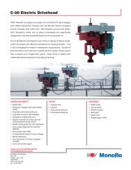
HK20000<br />
The HK20000 is a tool designed for making up and breaking connections of<br />
casing. The HK20000s can be assembled for either making-up or break-out.<br />
The rotor support design has the cam followers attached directly to the rotor,<br />
providing support for a smooth and quiet operation. A priority 4-way valve<br />
minimizes possible gear train damage. The power assisted gear shift assures<br />
efficient operation. Accommodations for torque return are standard. A load cell<br />
and torque guage are available as accessories. A two-speed gear box uses a<br />
cluster gear, high and low speed gears and pinion shaft. The single door design<br />
is simple to operate, has fixed guide support for the rotor.The door interlock<br />
system increases safety because the tong will not rotate with the door open.<br />
The larger door helps to cover rotating parts and is load carrying, thus adding<br />
strength. A single hanging bar arrangement is easier to adjust and provides<br />
maximum clearance making our HK20000 power casing tong safe to work with<br />
and work around.<br />
TEChNiCAL SpECiFiCATiONS<br />
Description Imperial Metric<br />
Size range 4” – 14” 102-356 mm<br />
Torque low gear 20,000 ft.lbs @ 2300 psi 27,000Nm @ 14,000 kPa<br />
Torque high gear 4,900 ft.lbs @ 2300 psi 6,650 Nm @ 14,000 kPa<br />
Maximum intermittent torque 25,000 ft.lbs @ 2,500 psi 34,000 Nm @ 17,500 kPa<br />
Rpm in low gear 17 rpm 17 rpm<br />
Rpm in high gear 70 rpm 70 rpm<br />
Power requirements: Volume 66 gpm @ 1,000 psi 250 ltr/ min @ 7,000 kPa<br />
Pressure (max.) 2,500 psi 17,200 kPa<br />
Dimensions (L x W x H) 62” x 37" x 54” 1,571 x 940 x 1372 mm<br />
Torque arm length back-up eye to center line of pipe 39” 1,007 mm<br />
Weight 1,950 lbs 886 kg<br />
MAiN pArT NuMBErS<br />
Description Part number<br />
Main assembly 8532-5000-10<br />
OpTiONAL EquipMENT pArT NuMBErS<br />
Description Part number<br />
Suspension spring assembly 8532-5108<br />
Tong torque assembly 8532-5119<br />
SiZE EquipMENT<br />
Pipe Size Jaw Assembly (2 pc) Guide ring (1 pc) Pipe Size Jaw Assembly (2 pc) Guide ring (1 pc)<br />
3.1/2" 200708-1<br />
7" 8547-5026<br />
4" 50006093-1 201107-6 7.5/8" 8547-5027<br />
4.1/2" 8547-5211 8.5/8" 8547-5028<br />
4.3/4" 8547-5205<br />
9.5/8" 8547-5029<br />
5" 8547-5206 201107-1 10.3/4" 8547-5030<br />
5.1/2" 8547-5207 11.3/4" 8547-5031<br />
5.3/4" 200692<br />
12" 8547-5032<br />
6" 8547-5208 12.3/4" 200690<br />
6.3/8" 200688-1 201107-2 13.3/8" 8547-5033<br />
6.5/8" 8547-5209 13.1/2" 8547-5033-1<br />
6.7/8" 200689-1 13.5/8" 50000629-1<br />
14" 8547-5034<br />
201107-3<br />
201107-4<br />
WWW.NOV.COM
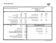
SSW10 PNEUMATIC SPINNING WRENCH<br />
The NOV Safety Spinning Wrench, SSW 10, is a pneumatically powered tool for spinning<br />
drill pipe from 3.1 /2" to 5.1 /2" O.D. Using the proven principle of frictional drive contact,<br />
the spinning wrench can spin drill pipe in or out quickly and efficiently without damage to<br />
expensive drill pipe and without the hazards of the dangerous spinning chain.<br />
TEChNiCAL SpECiFiCATiONS<br />
Description Imperial Metric<br />
Size range 3.1 /2" - 5.1 /2" 89 -140 mm<br />
Air pressure 90 to 125 psi 620 to 860 kPa<br />
Air consumption 240 cfm 510 dm3 /s<br />
Rpm (5" pipe) 80-100 rpm 80-100 rpm<br />
Torque (5" pipe) 1,000 ft.lbs 1,350 Nm<br />
Weight 810 lbs 368 kg<br />
Height 31.5" 800 mm<br />
Length 55" 1,397 mm<br />
Width 21" 533 mm<br />
MAiN pArT NuMBEr<br />
Assembly number w/o rollers:<br />
10426<br />
Assembly number with rollers:<br />
10426-35 3.1 /2" rollers<br />
10426-45 4.1 /2" rollers<br />
10426-50 5" rollers<br />
10426-55 5.1 /2" rollers<br />
SiZE EquipMENT<br />
Roller assemblies (2 required):<br />
Pipe OD 3.1 /2" 4.1 /2" 5" 5.1 /2"<br />
Part No 12035 12045 12050 12055<br />
WWW.NOV.COM<br />
POWER <strong>TOOLS</strong><br />
11
POWER <strong>TOOLS</strong><br />
12<br />
SSW30 HYDRAULIC SPINNING WRENCH<br />
The hydraulically powered SSW30 can spin drill pipe and drill<br />
collars from 2.7/8" to 9.1/2" O.D. with no adjustments necessary. Its<br />
abundant power will bump up shoulders tight enough so each joint is<br />
quickly torqued.<br />
This lightweight tool is narrower and has lower profile than previous<br />
spinning wrench designs. It achieves its compact shape by using one<br />
large cylinder for clamping.<br />
TEChNiCAL SpECiFiCATiONS<br />
Description Imperial Metric<br />
Size range 2.7/8" - 9.1 /2" OD 73-241 mm OD<br />
Normal operating hydraulic pressure 2,000 psi 13,789 Kpa<br />
Torque (5" dia. pipe) 900 to 1,000 ft.lbs 1,215-1,350 Nm<br />
Rpm (5" dia. pipe) 100 rpm 100 rpm<br />
Weight 850 lbs 385 kg<br />
Hydraulic power requirement 29 to 45 gpm 109 to 170 lpm<br />
MAiN pArT NuMBErS<br />
Assembly number<br />
Closed center: 19000-6<br />
Open center: 19000-7<br />
OpTiONAL EquipMENT pArT NuMBErS<br />
Description Assembly number<br />
Pressure hose: 58314-*<br />
Return hose: 58518-*<br />
*Specify length 6; 15; 25; 35 or 50 feet<br />
WWW.NOV.COM
SSW40 PNEUMATIC SPINNING WRENCH<br />
An easy adjustment screw eliminates the need to change rollers and can accommodate drill pipe and<br />
drill collars from 3.1 /2" to 9.1 /2" OD.<br />
The speed of the SSW40’s four drive rollers, powered by two motors, is precisely controlled by the<br />
operator to permit the slow walking in of drill collars or fast spinning in or out when tripping pipe. In<br />
a typical spinning operation the rig hand swings the SSW40 onto the pipe just above the joint upset.<br />
The clamp control is pulled and the throttle handle actuated to spin in or out with absolute precision.<br />
For added safety a spin direction lockout feature is included to prevent spinning pipe in wrong<br />
direction and comes with added safety valve, which prevents the tool from being closed without pipe<br />
in tool.<br />
TEChNiCAL SpECiFiCATiONS<br />
Description Imperial Metric<br />
Size range OD Drill Pipe and Drill Collars: 3 .1 /2" - 9.1 /2" 89-241 mm<br />
Air pressure Min/Max: 90 - 125 psi 620 - 860 kPa<br />
Max. air consumption: 250 cfm 530 dm3/s<br />
Max. stall torque (5" dia. pipe): 1,100 ft.lbs 1,490 Nm<br />
Weight: 850 lbs 385 kg<br />
MAiN pArT NuMBErS<br />
Assembly number:<br />
73109<br />
WWW.NOV.COM<br />
POWER <strong>TOOLS</strong><br />
13
POWER <strong>TOOLS</strong><br />
14<br />
KS6600 PNEUMATIC KELLY SPINNER<br />
KS6800 HYDRAULIC KELLY SPINNER<br />
Models 6600 and 6800 Kelly Spinners can be used for rotating drill pipe slowly, for<br />
limited rathole and mousehole drilling and making fast kelly connections. These units<br />
are completely reversible; the driller can spin-out, as well as spin-in, when making<br />
connections, therefore, spinning chains are not required.<br />
TEChNiCAL SpECiFiCATiONS<br />
Description Imperial Metric<br />
Connections 6.5/8" API Reg LH 168.275 mm API Reg LH<br />
Height 38.1 /2" 978 mm<br />
Diameter 28" 711 mm<br />
Weight 1,110 Lbs 504 kg<br />
Oil SAE 40, Capacity 4.1 /4 gal 4.8 l<br />
Stall torque 1,200 ft.lbs 1,622 Nm<br />
Rpm 110 rpm 110 rpm<br />
Flow (Air 6600) 320 cfm 680 dm3/s<br />
Flow (Hydraulic 6800) 24 gpm 91 lpm<br />
Rotation Right and Left Right and Left<br />
MAiN pArT NuMBErS<br />
Part number Assembly description<br />
70876Y Pneumatic Kelly Spinner Model 6600 complete with thread protectors, control valve, filter lubricator, and 62 foot hoses:<br />
70877Y Same as above with 77 foot hoses:<br />
70867Y Hydraulic Kelly Spinner Model 6800 complete with thread protectors, control valve, filter lubricator, and 62 foot hoses:<br />
70868Y Same as above with 77 foot hoses:<br />
WWW.NOV.COM
TW61 HYDRAULIC TORQUE WRENCH<br />
The NOV TW61 makes-up and breaks-out drill pipe and drill collars from<br />
4" to 8.1 /2" OD. Torque is adjustable and can be pre-set to the required<br />
value. Upper and lower gripping structures provide the required torque.<br />
The TW61 can rotate the tool joint pin up to 34°, to produce the desired<br />
torque while providing its own back-up. A built-in tugger is provided to<br />
pull the TW61 back out of the way while lowering or raising pipe stands.<br />
The tugger can also be used to assist in pulling the TW61 to a storage<br />
position. The tool has 6-foot vertical travel range so it can locate at the<br />
exact tool joint height.<br />
TEChNiCAL SpECiFiCATiONS<br />
Description Imperial Metric<br />
Size 4" - 8.1 /2" 102-216 mm<br />
Make-up Torque 63,000 ft.lbs 85,000 Nm<br />
Break-out Torque 75,000 ft.lbs 101,000 Nm<br />
Power Requirements 30-35 gpm @ 2,000 psi 114-133 lpm @13,789 Kpa<br />
Air Pressure (for Tugger) 90-125 psi 620-860 kPa<br />
Weight 3,190 lbs 1,450 kg<br />
Vertical Positioning (Total travel) 72" 1,830 mm<br />
Rate of Travel 2" / s 50.8 mm / s<br />
Cycle Time @ 40 gpm @ 151 lpm<br />
Clamping Both Jaws 2.5 s 2.5 s<br />
Clamping Upper Jaw 1.25 s 1.25 s<br />
Torquing 34° 2 s 2 s<br />
MAiN pArT NuMBErS<br />
Part number Assembly description<br />
19999-12 TW61<br />
WWW.NOV.COM<br />
POWER <strong>TOOLS</strong><br />
15
POWER <strong>TOOLS</strong><br />
16<br />
WWW.NOV.COM
HYDRAULIC POWER UNITS &<br />
CONTROL PANELS<br />
WWW.NOV.COM<br />
POWER UNITS & CONTROL PANELS<br />
17
POWER UNITS & CONTROL PANELS<br />
18<br />
HYDRAULIC POWER UNIT<br />
HKB (CE + ATEX EXPLOSION PROOF) power units<br />
Since the introduction of the HKB35 and HKB66, NOV has<br />
continuously worked towards improving the efficiency, reliability<br />
and safety of its design. This expanded product range will<br />
respond to the industry demands for reliable easy maintenance<br />
power units built according to ATEX-rules (Explosion Safety)<br />
for safer operation.<br />
HKB FEATURES<br />
•<br />
•<br />
•<br />
Variable displacement piston pump, stops the flow at<br />
maximum pressure to prevent unnecessary heating up<br />
of the oil.<br />
A power compensator is mounted to prevent an overload<br />
of the electric motor<br />
Automatic temperature control. The cooler starts<br />
automatically at an oil temperature inside the tank of<br />
38ºC (100ºF). The unit automatically shuts down if the oil<br />
temperature inside the tank reaches 70ºC (158ºF)<br />
• Automatic oil level safety. Unit automatically shuts down if<br />
the oil level inside the tank is too low.<br />
• Pressure and return connections by with quick disconnect<br />
couplings<br />
• Electric powered<br />
• Skid mounted unit unit van be lifted using a forklift or<br />
crane<br />
• HKB units can be lifted using a forklift or a crane.<br />
• Maximum pressure 2500 psi (175 bar)<br />
• Return line equipped with contamination indicator<br />
OPTIONS<br />
• Available in various pressure and flow configurations<br />
• Available for standard, arctic and desert ambient<br />
temperatures.<br />
• Available in 50 or 60Hz, from 360 to 480 Volts. Other<br />
supply power on request.<br />
• Diesel HKB’s on request.<br />
• Available with remote starter kit<br />
• Available HKB140D dual pump with 100% redundancy.<br />
• Air-over-Hydraulic Power Unit HKB3<br />
ATEX: EXPLOSION SAFETY<br />
•<br />
•<br />
HKB units are built according requirements of the<br />
European directive EN 982 and EN 94/9/EC for use in<br />
potentially explosive atmosphere.<br />
Standard ATEX compliance according to Ex II 2G<br />
T3 EEx-e IIB T3 for use in zone 2 (category 3) as a<br />
minimum.<br />
FLOW <strong>AND</strong> PRESSURE<br />
• Fixed pressure - Fixed flow (standard)<br />
• Fixed pressure - Adjustable flow<br />
• Adjustable pressure - Adjustable flow<br />
• Adjustable pressure - Fixed flow<br />
AMBIENT TEMPERATURE<br />
• -10° to +40°C (standard)<br />
• 0° to 50° C (Desert)<br />
• -40° to + 10°C (Arctic)<br />
POWER SUPPLY<br />
• 360 up to 480 V<br />
• 50 or 60 Hz<br />
hKB3 pOWEr Air-OVEr-hYDrAuLiC pOWEr<br />
uNiT<br />
The HKB-3 is an air driven hydraulic power unit which supplies hydraulic fluid under<br />
pressure to the FMS.<br />
pArT NuMBErS hKB3<br />
50007090 HKB3<br />
50007091 HKB3 with remote control<br />
quiCK rEFErENCE FOr EXiSTiNG <strong>TOOLS</strong><br />
ORDERING INFORMATION<br />
To order the HKB with the proper specifications, choose from different flow<br />
settings, temperatures listed.<br />
HKB Tool interface Required<br />
pressure [psi/<br />
kPa]<br />
Required<br />
flow<br />
[gpm/<br />
lpm]<br />
Available<br />
units<br />
50Hz 60Hz<br />
71 FMS375 2,000 / 13,790 5/18.9 No Yes<br />
71 PS21/30 2,500 / 17,240 10/38 Yes Yes<br />
71 BX3,4,5,S 2,000 / 13,789 7/26.5 Yes Yes<br />
71 H-SJH 2,000 / 13,789 5/18.9 Yes Yes<br />
71 All E/S's 2,000 / 13,789 12/45 Yes Yes<br />
71 FMS275 2,000 / 13,789 12/45 Yes Yes<br />
71 CRT350 2,000 / 13,789 16/60 Yes Yes<br />
71 CRT500 2,000 / 13,789 16/60 Yes Yes<br />
100 KS6800 2,000 / 13,790 24/91 Yes Yes<br />
100 TW61 2,000 / 13,790 35/132 Yes Yes<br />
100 SSW30 2,000 / 13,790 45/170 Yes Yes<br />
100 FMS375 2,000 / 13,790 32/121 Yes No<br />
100 ST80 2,000 / 13,790 45/151 Yes Yes<br />
140 IR2100 2,000 / 13,790 32/121 Yes Yes<br />
140 HK20000 2,500 / 17,240 66/250 No Yes<br />
180 HK20000 2,500 / 17,240 66/250 Yes No<br />
180 SSW30 2,500 / 17,240 66/250 Yes Yes<br />
140D TDS+AR3200 2,500 / 17,240 66/250 Yes Yes<br />
HKB3 FMS375 2,000 / 13,790 32/121 n/a n/a<br />
WWW.NOV.COM
SELECTiNG ThE hKB*<br />
HKB71<br />
• Pump 71 cc/rev<br />
• Qmax at 1,500 rpm [50 Hz]: 106.5 lpm=27 gpm<br />
• Qmax at 1,750 rpm [60 Hz]: 124 lpm=32 gpm<br />
• Maximal pressure: 2,500 psi / 17,240 kPa<br />
• Maximum power output: 15 kW<br />
• Dimensions LxWxH [inches/m]: 78x43x60/2x1.1x1.5<br />
HKB100<br />
• Pump 100 cc/rev<br />
• Qmax at 1,500 rpm [50 Hz]: 150 lpm=38 gpm<br />
• Qmax at 1,750 rpm [60 Hz]: 175 lpm=46 gpm<br />
• Maximum pressure: 2,500 psi / 17,240 kPa<br />
• Maximum power output: 22 kW<br />
• Dimensions LxWxH [inches/m]: 79x43x60/2x1.1x1.5<br />
HKB140 + HKB 140 D (dual pump)<br />
• Pump 140 cc/rev<br />
• Qmax at 1,500 rpm [50 Hz]: 210 lpm=53 gpm<br />
• Qmax at 1,750 rpm [60 Hz]: 245 lpm=65 gpm<br />
• Maximum pressure: 2,500 psi / 17,240 kPa<br />
• Maximum output power: 30 kW<br />
• Dimensions Single Pump LxWxH [inches/m]: 87x43x60/2.2x1.1x1.5<br />
HKB180<br />
• Pump 180 cc/rev<br />
• Qmax at 1,500 rpm [50 Hz]: 270 lpm=69 gpm<br />
• Qmax bij 1,750 rpm [60 Hz]: 315 lpm=95 gpm<br />
• Maximum pressure: 2,500 psi / 17,240 kPa<br />
• Maximum output power: 37 kW<br />
• Dimensions LxWxH [inches/m]: 95x43x60/2.4x1.1x1.5<br />
*All data subject to confirmation by manufacturer<br />
WWW.NOV.COM<br />
HKB3<br />
• Pump 180 cc/rev<br />
• Qmax: 7.5 lpm = 2 gpm<br />
• Max "Slips down" pressure is preset at 2,500 psi / 17,200 kPa<br />
• Max "Slips up" pressure is preset at 1,000 psi / 6,900 kPa<br />
• Minimum airpressure 95 psi / 690 kPa<br />
• Maximum airpressure 300 psi / 2,100 kPa<br />
• Air consumtion at input pressure 95 psi / 6,5 Bar / max. 75cfm /<br />
2.12 m³/min<br />
• Dimensions LxWxH [inches/mm]:<br />
34 x 30 x 55.75 / 863.6 x 762 x 1416<br />
For details or a quotation, please contact NOV<br />
POWER UNITS & CONTROL PANELS<br />
19
POWER UNITS & CONTROL PANELS<br />
20<br />
HYDRAULIC ST<strong>AND</strong> ALONE CONTROL PANEL BX/BXS<br />
Portable fully hydraulic control panel to operate BX and BXS through a portable service loop. Also suitable to<br />
operate the BX universal rotator.<br />
The panel is suitable to operate the following rotary spiders/slips: FMS275, FMS375, PS21, PS30 and hydraulic<br />
Elevator / Spiders 14" & 24".<br />
The panel has an interlock function between the elevator and the rotary spider.<br />
TEChNiCAL SpECiFiCATiONS<br />
Weight & Dimensions of Panel<br />
Weight Stand Alone Control Panel [lbs/kg] 450 / 200<br />
Dimensions Overall: Height x Width x Depth [inches/mm] 47.5 x 27.6 x 19.7 / 1210 x<br />
700 x 500<br />
Weight & Dimensions of Service Loops<br />
Service Loop is suitable for BX 3 thru 5 and BXS .<br />
Service Loop is suitable for Universal Rotator (Single Arm, pn 50004130) ONLY<br />
Length (Coupling to Coupling) [ft/m] 197 / 60<br />
Weight (Oil filled) [lbs/kg] 800 / 365<br />
Service Loops is supplied with two loop hanger assemblies to provide interface<br />
point to the Derrick (via Tugger) and the Top-Drive (RLA Link-ear or other<br />
suitable attachment point).<br />
MAiN pArT NuMBErS<br />
Part number Description<br />
50000350 Control panel ass'y<br />
50000360 Service loop<br />
OpTiONAL EquipMENT pArT NuMBErS<br />
Part number Description<br />
50000350-13 1 year spares for control panel and service loop<br />
200977-8 Hose kit for FMS375<br />
50005249 Hose kit for FMS275<br />
50008610-21 Hose kit for PS21<br />
50008610-21 Hose kit for NOV 14" Hydr. Spider pn 50006046Y1<br />
WWW.NOV.COM
FMS CONTROL PANELS<br />
The FMS is connected to the panel by applying two hoses between the FMS and the two quick<br />
disconnect couplers (Slips up, Slips down) on the panel.<br />
On the extra connections of the control panel (Pressure power tong, Return power tong) a<br />
power tong or secondary tool can be connected by using hydraulic hoses. This tool also needs<br />
to be a open center system.<br />
The panel pn 50006538 allows to control both the FMS and power tong. No power fluctuations<br />
will occur, allowing a consistent operation and reliable and nearly absolute torque read out.<br />
TEChNiCAL SpECiFiCATiONS<br />
Hydraulic characterestics<br />
Maxiumim pressure [psi/kPa] 3,000 / 20,684<br />
Maxiumum flow [gpm/lpm] 50 / 200<br />
Pressure at "pressure power-unit" connection [psi/kPa] 2,600-3,000 / 17,926-20,684<br />
Back pressure at "return power unit" connection [psi/kPa] 0-200 / 0-1,378<br />
Power unit flow range [gpm/lpm] 5-50 / 20-200<br />
Pressure on "slips down" connection [psi/kPa] 1,300-2,450 / 8,963-16,892<br />
Standard settings on "slips down" connection [psi/kPa] 1,800 / 12,410<br />
Pressure on "slip up" connection [psi/kPa] 1,000 / 6,894<br />
Max. output flow to FMS [gpm/lpm] 15 / 60<br />
Output flow to pressure power tong When the FMS is moving; no flow is available. With the FMS stationary, see<br />
power unit flow range (minus leakage flow)<br />
Nominal volume of accumulator [gallon/l] 0.18 / 0.7<br />
Ni pre-charge pressure [psi/kPa] 1,960 / 13,513<br />
Maxiumum accumulator pressure [psi/kPa]<br />
Pneumatic characterestics<br />
3,000 / 20,684<br />
Pressure at air pressure connection [psi/kPa] 90-230 / 620-1585<br />
Air flow [gpm/lpm]<br />
Physical<br />
396 / 1,500<br />
Dimensions (L x W x H) [inches/mm] 29.53" x 22.83" x 21.65" / 750x580x55<br />
Weight [Lbs/kg] 265 / 120<br />
MAiN pArT NuMBEr<br />
Part number Description<br />
50006538 Control panel<br />
WWW.NOV.COM<br />
POWER UNITS & CONTROL PANELS<br />
21
POWER UNITS & CONTROL PANELS<br />
22<br />
CRT350/500 INTERLOCK PANEL<br />
The CRT350/500 Gated Operator Control Panel contains all required valves and control handles to<br />
remotely operate the following tools.<br />
• The CRT350<br />
• The CRT500<br />
• The CRT350’s hydraulic single joint elevator (H-SJH)<br />
• The CRT500's hydraulic single joint elevator (UX)<br />
• The Hydraulic Rotary Slips<br />
The control panel connects to both the CRT350/500 and it’s hydraulic single joint elevator H-SJH/UX<br />
(via the service loop) as well as the Hydraulic Rotary Slips.<br />
TEChNiCAL SpECiFiCATiONS<br />
Subject Value<br />
Weight [lbs / kg] 250 / 450<br />
Dimensions [inches / mm] 27,6 x 19,7 x 47,5 / 675 x 500 x 1206<br />
MAiN pArT NuMBErS<br />
Part number Part<br />
50008610 Control panel<br />
50008551 Service loop<br />
OpTiONAL EquipMENT pArT NuMBErS<br />
Part number Description<br />
50008610-13 1 year spares for control panel and service loop<br />
200977-8 Hose kit for FMS375<br />
50005249 Hose kit for FMS275<br />
50008610-21 Hose kit for PS21<br />
50008610-21 Hose kit for NOV 14" Hydr. Spider pn 50006046Y1<br />
WWW.NOV.COM
WWW.NOV.COM<br />
DYNAPLEX HOOKS<br />
DYNAPLEX HOOKS<br />
23
DYNAPLEX HOOKS<br />
24<br />
DYNAPLEX HOOKS<br />
The Dynaplex hook is a premium-quality rotary hook for heavy-duty drilling<br />
requirements. Special features: Hydraulic snubber, flexible pin connection and<br />
hook positioner. The hook positioner provides faster, safer operation and cuts<br />
down round-trip time. When going in the hole, the positioner automatically<br />
rotates the elevator into the correct position for the derrickman to catch the next<br />
stand of pipe. The positioner also prevents the hook and elevator from being<br />
rotated by the “spin-up” of drill pipe going in the hole. Operators may desire to<br />
direct-connect the Dynaplex hook to the traveling block.<br />
TEChNiCAL SpECiFiCATiONS<br />
Specifications 51000 5750 5500 5350<br />
Capacity [Ton/sTon] 907 / 1,000 680 / 750 453 / 500 317 / 350<br />
Hook complete with positioner [lbs] 32,076 18,090 9,950 5,340<br />
Hook complete with positioner [kg] 14,550 8,205 4,513 2,876<br />
MAiN pArT NuMBErS<br />
Model Hook Complete With Positioner<br />
51000 38327Y<br />
5750 31108Y<br />
5500 26955Y<br />
5350 24767Y<br />
DiMENSiONAL DATA DYNApLEX hOOKS - BLOCK COMBiNATiONS<br />
*information on request<br />
WWW.NOV.COM
A<br />
C<br />
D<br />
V<br />
O<br />
Ref. 51000 5750 5500 5350<br />
No. [inches] [mm] [inches] [mm] [inches] [mm] [inches] [mm]<br />
A* 187.3/4 4768.85 162 4114.80 139.1/2 3543.30 126.3/4 3219.45<br />
B* 150.7/8 3832.23 129.1/2 3289.30 109.3/8 2778.13 97.1/2 2476.50<br />
C* 118.3/4 3016.25 102.1/2 2604.00 85.3/8 2168.53 72.5/8 1844.68<br />
D 6.5/8 168.28 6.5/16 160.34 7.3/8 187.33 9 228.60<br />
E 15.1/2 393.70 13.1/2 342.90 12.1/2 317.50 11 279.40<br />
F 17.1/2 444.50 15 381.00 13 330.20 11.1/4 285.75<br />
G 23.3/8 594.00 20 508.00 16.5/8 422.28 14 355.60<br />
H 41 1041.40 35.1/4 895.35 26.1/4 666.75 21 533.40<br />
I 21.3/8 542.93 19 482.60 17.3/4 450.85 18.1/4 463.55<br />
J 56.1/2 1435.10 48.1/4 1225.55 36.1/2 927.10 29.3/4 755.65<br />
K 6.1/2 165.10 5.3/4 146.05 4 101.60 3.1/4 82.55<br />
L 36.3/4 933.45 32.1/4 819.15 26.3/4 679.45 22 558.80<br />
M 48.3/4 1238.25 43.1/2 1104.90 37.3/4 958.85 30.3/4 781.05<br />
N 46.7/8 1190.63 39.11⁄16 1008.06 34.1/4 869.95 34.1/8 866.78<br />
O 9 228.60 7 177.80 6.1/2 165.10 5.3/8 136.53<br />
P 12.1/2 317.50 10.3/4 273.05 8.1/2 215.90 7.1/2 190.50<br />
Q 10.1/2 266.70 8.1/2 215.90 7 177.90 6.1/2 165.10<br />
R 6 152.40 3.1/4 82.55 3.1/4 82.55 3 76.20<br />
S 6 152.40 6 152.40 4.1/2 114.30 4 101.60<br />
T 5 127.00 4 101.60 4 101.60 4 101.60<br />
U 18.7/8 479.43 16 406.40 14.1/4 361.95 13.1/4 336.50<br />
V 25.5/8 650.88 22.1/2 571.50 20.3/8 517.53 19 482.60<br />
W 9 228.60 8 203.20 8.1/4 209.55 6 152.40<br />
WWW.NOV.COM<br />
R<br />
K<br />
T<br />
W<br />
L<br />
M V U<br />
B<br />
Q<br />
J<br />
U<br />
S<br />
E<br />
E G<br />
P<br />
DYNAPLEX HOOKS<br />
25
DYNAPLEX HOOKS<br />
26<br />
WWW.NOV.COM
WWW.NOV.COM<br />
LINKS<br />
LINKS<br />
27
LINKS<br />
28<br />
WELDLESS LINKS<br />
Weldless Links are forged from a single piece of high-grade alloy steel<br />
to provide maximum tensile strength. More weight and “plus-diameter”<br />
in critical areas make these links extra strong. Short upper eye design<br />
means better balance and easier elevator handling, while reducing wear<br />
of the eye section against the swivel bail or body.<br />
TEChNiCAL SpECiFiCATiONS*<br />
Link P/N Nominal<br />
[inches]<br />
Dim. A B C D E F G H<br />
250 [sTon]<br />
16363 2.1/4 [inches] 2.5/16" 5.1/2" 7.1/2" 2.7/8" 9.1/2" 12" 5" 15"<br />
"<br />
350 [sTon]<br />
" [mm] 58.7 139.7 190.5 73 241.3 304.8 127 381<br />
26940 2.3/4 [inches] 2.13/16" 5.5/8" 8.3/8" 3.1/2" 9.1/2" 12" 5" 15"<br />
"<br />
500 [sTon]<br />
" [mm] 71.4 142.9 212.7 88.9 241.3 304.8 127 381<br />
25469 3.1/2 [inches] 3.5/8" 6.1/2" 10.1/8" 4.1/2" 9.1/2" 12" 6" 17"<br />
"<br />
750 [sTon]<br />
" [mm] 92.1 165.1 257.2 114.3 241.3 304.8 152.4 431.8<br />
16143 4.3/4 [inches] 7.1/2" 10" 14.5/8" 6" 10" 14.5/8" 7.1/2" 23"<br />
"<br />
1,000 [sTon]<br />
" [mm] 190.5 254 371.5 152.4 254 371.5 190.5 584.2<br />
70101 5.1/2 [inches] 8.1/4" 12.3/4" 17.1/2" 6" 12.3/4" 17.1/2" 8.1/4" 29.1/4"<br />
"<br />
1,250 [sTon]<br />
" [mm] 209.6 323.9 444.5 152.4 323.9 444.5 209.6 743<br />
M614000320 5.1/2 [inches] 8.1/4" 12.3/4" 17.1/2" 6" 12.3/4" 17.1/2" 8.1/4" 29.1/4"<br />
" " [mm] 209.6 323.9 444.5 152.4 323.9 444.5 209.6 743<br />
* Note: The dimensions are nominal. The actual dimensions may vary due to manufacturing tolerances. All API contact radius are manufactured<br />
according to API specifications.<br />
WWW.NOV.COM
pArT NuMBErS WELDLESS LiNKS<br />
Part No. Nominal link size [inches] Size [inches/mm] Rated Capacity per Set [sTon/Ton] Weight per Set [lbs/kg]<br />
16363Y1060 2.1/4 x 60 60 / 1,524 250 / 226.8 480 / 218<br />
16363Y1072 2.1/4 x 72 72 / 1,829 250 / 226.8 530 / 241<br />
16363Y1084 2.1/4 x 84 84 / 2,134 250 / 226.8 580 / 264<br />
16363Y1096 2.1/4 x 96 96 / 2,438 250 / 226.8 630 / 286<br />
16363Y1108 2.1/4 x 108 108 / 2,743 250 / 226.8 680 / 309<br />
16363Y1132 2.1/4 x 132 132 / 3,353 250 / 226.8 780 / 355<br />
16363Y1168 2.1/4 x 168 168 / 4,267 250 / 226.8 880 / 399<br />
26940Y1060 2.3/4 x 60 60 / 1,524 350 / 317.5 620 / 282<br />
26940Y1072 2.3/4 x 72 72 / 1,829 350 / 317.5 685 / 311<br />
26940Y1084 2.3/4 x 84 84 / 2,134 350 / 317.5 740 / 336<br />
26940Y1096 2.3/4 x 96 96 / 2,438 350 / 317.5 805 / 366<br />
26940Y1108 2.3/4 x 108 108 / 2,743 350 / 317.5 870 / 395<br />
26940Y1120 2.3/4 x 120 120 / 3,048 350 / 317.5 935 / 425<br />
26940Y1132 2.3/4 x 132 132 / 3,353 350 / 317.5 1,000 / 454<br />
26940Y1144 2.3/4 x 144 144 / 3,657 350 / 317.5 1,064 / 483<br />
26940Y1150 2.3/4 x 150 150 / 3,810 350 / 317.5 1,095 / 498<br />
26940Y1168 2.3/4 x 168 168 / 4,267 350 / 317.5 1,190 / 541<br />
26940Y1180 2.3/4 x 180 180 / 4,572 350 / 317.5 1,255 / 571<br />
26940Y1192 2.3/4 x 192 192 / 4,877 350 / 317.5 1,320 / 600<br />
26940Y1200 2.3/4 x 200 200 / 5,080 350 / 317.5 1,363 / 618<br />
26940Y1216 2.3/4 x 216 216 / 5,486 350 / 317.5 1,450 / 659<br />
26940Y1240 2.3/4 x 240 240 / 6,096 350 / 317.5 1,580 / 718<br />
26940Y1264 2.3/4 x 264 264 / 6,705 350 / 317.5 1,770 / 800<br />
26940Y1290 2.3/4 x 290 290 / 7,366 350 / 317.5 1,944 / 882<br />
26940Y1350 2.3/4 x 350 350 / 8,890 350 / 317.5 2,180 / 988<br />
26940Y1360 2.3/4 x 360 360 / 9,144 350 / 317.5 2,235 / 1,014<br />
26940Y1480 2.3/4 x 480 480 / 12,192 350 / 317.5 2,885 / 1,306<br />
26940Y1540 2.3/4 x 540 540 / 13,716 350 / 317.5 3,187 / 1,446<br />
26940Y1600 2.3/4 x 600 600 / 15,240 350 / 317.5 3,408 / 1,546<br />
25469Y1072 3.1/2 x 72 72 / 1,829 500 / 453.6 705 / 320<br />
25469Y1096 3.1/2 x 96 96 / 2,438 500 / 453.6 1058 / 480<br />
25469Y1108 3.1/2 x 108 108 / 2,743 500 / 453.6 1,450 / 659<br />
25469Y1120 3.1/2 x 120 120 / 3,048 500 / 453.6 1,622 / 736<br />
25469Y1132 3.1/2 x 132 132 / 3,353 500 / 453.6 1,670 / 759<br />
25469Y1144 3.1/2 x 144 144 / 3,688 500 / 453.6 1,780 / 809<br />
25469Y1160 3.1/2 x 160 160 / 4,064 500 / 453.6 1,927 / 876<br />
25469Y1168 3.1/2 x 168 168 / 4,267 500 / 453.6 2,000 / 909<br />
25469Y1180 3.1/2 x 180 180 / 4,572 500 / 453.6 2,110 / 959<br />
25469Y1190 3.1/2 x 190 190 / 4,826 500 / 453.6 2,202 / 998<br />
25469Y1192 3.1/2 x 192 192 / 4,826 500 / 453.6 2,220 / 1,007<br />
25469Y1216 3.1/2 x 216 216 / 5,486 500 / 453.6 2,422 / 1,098<br />
25469Y1226 3.1/2 x 226 226 / 5,740 500 / 453.6 2,596 / 1,177<br />
25469Y1264 3.1/2 x 264 264 / 6,706 500 / 453.6 2,882 / 1,307<br />
25469Y1360 3.1/2 x 360 360 / 9,144 500 / 453.6 3,174 / 1,440<br />
25469Y1480 3.1/2 x 480 480 / 12,192 500 / 453.6 3,968 / 1,800<br />
25469Y1540 3.1/2 x 540 540 / 13,716 500 / 453.6 4,519 / 2,050<br />
WWW.NOV.COM<br />
LINKS<br />
29
LINKS<br />
30<br />
Part No. Nominal link size [inches] Size [inches/mm] Rated Capacity per Set [sTon/Ton] Appr. weight per Set [lbs/kg]<br />
16143Y1132 4.3/4 x 132 132 / 3,352 750 / 680.4 1,741 / 790<br />
16143Y1144 4.3/4 x 144 144 / 3,688 750 / 680.4 2,312 / 1,051<br />
16143Y1160 4.3/4 x 160 160 / 3,688 750 / 680.4 3,178 / 1,445<br />
16143Y1180 4.3/4 x 180 180 / 4,572 750 / 680.4 3,900 / 1,769<br />
16143Y1200 4.3/4 x 200 200 / 5,080 750 / 680.4 4,550 / 2,063<br />
16143Y1216 4.3/4 x 216 216 / 5,486 750 / 680.4 5,200 / 2,364<br />
16143Y1240 4.3/4 x 240 240 / 6,096 750 / 680.4 5,864 / 2,660<br />
16143Y1264 4.3/4 x 264 264 / 6,705 750 / 680.4 7,275 / 3,300<br />
16143Y1300 4.3/4 x 300 300 / 7,620 750 / 680.4 8,800 / 3,991<br />
70101Y1200* 5.1/2 x 200 200 / 5,080 1,000 / 907.2 5,100 / 2,315<br />
M614000320Y1180 5.1/2 x 180 200 / 5,080 1,250 / 1,133 4,550 / 2,063<br />
M614000320Y1200 5.1/2 x 200 200 / 5,080 1,250 / 1,133 5,100 / 2,315<br />
M614000320Y1240 5.1/2 x 240 200 / 5,080 1,250 / 1,133 7,275 / 3,300<br />
* Other lengths available on request.<br />
PERFECTION LINKS<br />
Dependable, efficient Perfection links are designed for light loads. They are<br />
made by forging, bending and electric welding of high-quality steel bar stock,<br />
which is then heat-treated and magnafluxed.<br />
pArT NuMBErS pErFECTiON LiNKS<br />
Part No. Size [inches/mm] Rated Cap per Set [sTon/Ton] Weight per Set [lbs/kg] Dimension X [inches/mm]<br />
200450Y130 2 x 30 / 50.8 x 762 100 / 89.3 49 / 108 30 / 762<br />
200450Y136 2 x 36 / 50.8 x 914 100 / 89.3 58 / 128 36 / 914<br />
200450Y142 2 x 42 / 50.8 x 1,067 100 / 89.3 67 / 148 42 / 1,067<br />
200450Y148 2 x 48 / 50.8 x 1,219 100 / 89.3 76 / 168 48 / 1,219<br />
200450Y160 2 x 60 / 50.8 x 1,524 100 / 89.3 95 / 208 60 / 1,524<br />
X<br />
WWW.NOV.COM
DC DOLLY<br />
Efficient method of handling drill collars without having to remove the elevator from the links.<br />
The drill collar assemblies are suitable for use in combination with the perfection links. The size<br />
range is from 2.7/8" plain to 6.5/8" IEU.<br />
pArT NuMBErS DC DOLLiES<br />
Part No.<br />
18° type<br />
Size [inches]<br />
31189Y1 4.1/2" IF & 5" IEU<br />
31189Y7 3.1/2" IF, Reg & FH<br />
31189Y10 5.1/2" IEU -18<br />
31189Y18<br />
Collar type<br />
5.7/8" IEU -18<br />
31189Y3 4.1/2" IF & 5" IEU<br />
31189Y5 4" IF & 4.1/2" Reg & FH<br />
31189Y9 4 FH<br />
31189Y12 3.1/2" IF & 5" IEU<br />
31189Y15 6.5/8" EU<br />
31189Y16 2.7/8" Plain<br />
WWW.NOV.COM<br />
LINKS<br />
31
LINKS<br />
32<br />
WWW.NOV.COM
WWW.NOV.COM<br />
ELEVATOR SELECTION<br />
CHARTS<br />
ELEVATOR SELECTION CHARTS<br />
33
ELEVATOR SELECTION CHARTS<br />
34<br />
ELEVATOR SELECTION CHARTS<br />
SLIP TYPE ELEVATORS Y SERIES<br />
Size Size Type Part number Cap. Max. Max. Link size (min / max)<br />
Weight Weight<br />
[inches] [mm] [sTon] [lbs] [kg] [inches] [mm] [inches] [mm]<br />
1.315" - 2.7/8" 33-73 MYT 29328Y 40 148 67 1.1/4" 32 2.3/4" 70<br />
1.315" - 3.1/2" 33-89 YT 55600Y 75 355 161 2.1/4" 57 2.3/4" 70<br />
2.3/8" - 3.1/2" 60-89 HYT 39284Y 150 740 336 2.1/4" 57 3.1/2" 89<br />
3.1/2" - 7" 89-178 YC 24140Y 75 445 206 2.1⁄4” 57 2.3⁄4” 70<br />
3.1/2" - 7" 89-178 MYC 200360Y 125 750 336 2.1⁄4” 57 2.3⁄4” 70<br />
2.7/8" - 7.3/4" 73-197 HYC BJ55310Y 200 997 452 2.1⁄4” 57 3.1⁄2” 89<br />
2.7/8" - 7.3/4" 73-197 HYC AO BJ70166Y 200 1465 665 2.1⁄4” 57 3.1⁄2” 89<br />
COLLAR TYPE CENTER LATCH ELEVATORS A SERIES<br />
1.050 " - 2.7/8" 28-73 TA 32387Y* 35 57 26 1.1/4" 32 1.3/4" 45<br />
2.3/8" - 5" 60-127 TMA 50006310Y * 100 121 55 1.3/4" 45 2.3/4" 70<br />
4.3/4" - 8.5/8" 121-219 TA 200000Y* 100 260 118 1.3/4" 45 2.3/4" 70<br />
4.1/2" - 8.5/8" 121-219 TA 32754Y* 150 370 168 1.3/4" 45 3.1/2" 89<br />
4.1/2" - 8.5/8" 121-219 TA AO 35636Y* 150 530 240 1.3/4" 45 3.1/2" 89<br />
8.1/2" - 11.1/4" 216-286 TA 39342Y* 150 524 238 1.3/4" 45 3.1/2" 89<br />
8.1/2" - 11.1/4" 216-286 TA AO 39343Y* 150 550 250 1.3/4" 45 3.1/2" 89<br />
2.7/8” - 4.3/4” 70 - 120 RGA 201360Y* 200 304 138 1.3/4" 45 2.3/4" 70<br />
3.1/2” - 7” 89 - 178 GA 200034Y* 350 608 276 2.1/4" 57 3.1/2" 89<br />
3.1/2” - 7” 89 - 178 GA AO 200035Y* 350 725 330 2.1/4" 57 3.1/2" 89<br />
4” - 7.5/8” 102 - 193 GGA 201385Y* 350 693 314 2.1/4" 57 3.1/2" 89<br />
4” - 7.5/8” 102 - 193 GGA AO 201380Y* 350 998 454 2.1/4" 57 3.1/2" 89<br />
18º CENTER LATCH ELEVATOR G SERIES<br />
2.3/8" - 5" 60-127 MG 30157Y* 100 233 106 1.3/4" 45 2.3/4" 70<br />
2.3/8" - 3.1/2" 60-89 RGG 200680Y* 150 304 138 1.3/4" 45 2.3/4" 70<br />
2.7/8" - 5.1/2" 89-140 MGG 35005Y* 250 608 276 2.1/4" 57 3.1/2" 89<br />
2.7/8" - 5.1/2" 89-140 MGG AO 36056Y* 250 720 327 2.1/4" 57 3.1/2" 89<br />
4" - 5.1/2" 102-140 GG 31068Y* 350 693 314 2.1/4" 57 3.1/2" 89<br />
4" - 5.1/2" 102-140 GG AO 35143Y* 350 1018 463 2.1/4" 57 3.1/2" 89<br />
4" - 6.5/8" 102-168 HGG 70013Y* 500 1029 467 2.1/4" 57 3.1/2" 89<br />
4" - 6.5/8" 102-168 HGG AO 70222Y* 500 1500 680 2.1/4" 57 3.1/2" 89<br />
18º CENTER LATCH ELEVATOR G SERIES (with wear bushing)<br />
2.7/8" - 5.1/2" 89-140 MGG 200058Y* 250 585 266 2.1/4" 57 3.1/2" 89<br />
2.7/8" - 5.1/2" 89-140 MGG AO 200057Y* 250 730 332 2.1/4" 57 3.1/2" 89<br />
4" - 5.1/2" 102-140 GG 200056Y* 350 680 310 2.1/4" 57 3.1/2" 89<br />
4" - 5.1/2" 102-140 GG AO 200024Y* 350 1028 468 2.1/4" 57 3.1/2" 89<br />
4" - 5.1/2" 102-140 HGG 200060Y* 500 1010 459 2.1/4" 57 3.1/2" 89<br />
4" - 5.1/2" 102-140 HGG AO 200059Y* 500 1510 685 2.1/4" 57 3.1/2" 89<br />
5.1/2" - 6.5/8" 140-168 HGG 200062Y* 500 1010 459 2.1/4" 57 3.1/2" 89<br />
5.1/2" - 6.5/8" 140-168 HGG AO 200061Y* 500 1510 685 2.1/4" 57 3.1/2" 89<br />
* bore code, see chapter "Elevator bore charts"<br />
WWW.NOV.COM
COLLAR TYPE SIDE DOOR ELEVATORS X SERIES<br />
Size Size Type Part number Cap. Max. Max. Link size (min / max)<br />
Weight Weight<br />
[inches] [mm] [sTon] [lbs] [kg] [inches] [mm] [inches] [mm]<br />
1.660" - 2.7/8" 42-73 SLX 33734Y* 65 50 23 1.3/4 45 2.1/4 57<br />
2.3/8" - 2.7/8" 60-73 SLX 33693Y* 100 75 34 1.3/4 45 2.3/4 70<br />
3.1/2'' - 4'' 89-101.6 SLX 33809Y* 100 114 58 1.3/4" 45 2.3/4" 70<br />
3.1/2'' - 5.3/4'' 89-146 SMX 50006430Y* 150 278 126 2.1/4" 57 2.3/4" 70<br />
4.1/2'' - 5.1/2'' 89-146 SLX 33854Y* 100 145 66 1.3/4" 45 2.3/4" 70<br />
5.1/2'' - 8.5/8'' 140-219 SLX 31239Y* 150 326 148 1.3/4" 45 3.1/2" 89<br />
6" - 9" 152-229 SMX 50006438Y* 150 291 132 2.1/4" 57 3.1/2" 89<br />
6" - 9" 152-229 SMX 50006426Y* 250 474 215 2.1/4" 57 3.1/2" 89<br />
9.5.8" - 10.3/4" 245-273 SLX 33950Y* 150 357 162 1.3/4" 45 3.1/2" 89<br />
9.1/8" - 13.3/8'' 231-340 SMX 50006454Y* 150 406 187 2.1/4" 57 3.1/2" 89<br />
9.1/8" - 13.3/8'' 231-340 SMX 50006740Y* 250 563 255 2.1/4" 57 3.1/2" 89<br />
9.1/8" - 13.3/8'' 231-340 SMX 50006440Y* 350 563 255 2.1/4" 57 3.1/2" 89<br />
13.5/8' 340 SX 29965Y* 350 1200 544 2.1/4" 57 3.1/2" 89<br />
9.5/8" - 13.5/8" 245-340 SX 29964Y* 500 1235 560 2.1/4" 57 3.1/2" 89<br />
11.3/4" - 13.3/8" 289-340 SLX 33982Y* 150 448 203 1.3/4" 45 3.1/2" 89<br />
13.1/2'' - 17.7/8'' 343-454 SMX 50006450Y* 250 679 308 2.1/4" 57 3.1/2" 89<br />
16" 406 SLX 34087Y* 150 1200 544 1.3/4" 45 3.1/2" 89<br />
16" 406 SX 30729* (8A only) 500 1200 544 2.1/4" 57 3.1/2" 89<br />
18'' - 24.1/2’’ 457-622 SMX 50006460Y* 250 902 409 2.1/4" 57 3.1/2" 89<br />
18.5/8" - 20" 473-508 SLX 33632Y* 150 705 320 1.3/4" 45 3.1/2" 89<br />
24.1/2" 622 SLX 34175Y* 250 1208 548 1.3/4" 45 3.1/2" 89<br />
26" - 30" 663-762 SLX DD 52755Y* 150 1820 826 1.3/4" 45 3.1/2" 89<br />
AUXILIARY ELEVATORS S SERIES<br />
2.3/8'' - 3.1/2'' 60-89 SJL 70499* 5 / 4.5 45 20<br />
4" - 5.1/2" 102-140 SJL 70500Y* 5 / 4.5 51 23<br />
6" - 7.5/8'' 152-194 SJL 70501Y* 5 / 4.5 72 32<br />
8.5/8'' - 10.3/4'' 219-273 SJL 70502Y* 5 / 4.5 98 44<br />
11.3/4'' - 14'' 298-340 SJL 70503Y* 5 / 4.5 121 55<br />
16'' - 20'' 406-508 SJL 70504Y* 5 / 4.5 233 105<br />
21'' - 24.1/2" 546-622 SJL 70505Y* 5 / 4.5 283 128<br />
2.7/8'' - 5.1/2'' 73-127 SPL 5° 200008Y* 5 / 4.5 77 35<br />
5.1/2'' - 7.5/8'' 140-194 SPL 5° 200010Y* 5 / 4.5 108 49<br />
8.5/8'. - 9.5/8'' 219-244 SPL 5° 200012Y* 5 / 4.5 145 66<br />
10.3/4" 273 SPL 5° 200013Y* 5 / 4.5 160 73<br />
2.3/8'' - 4.1/2" 60-114 SPL 12° 200014Y* 5 / 4.5 86 39<br />
2.3/8'' - 5'' 60-127 SPL 18° 200009Y* 5 / 4.5 79 36<br />
5.1/2'' - 6.5/8'' 140-168 SPL 18° 200011Y* 5 / 4.5 94 42<br />
DOUBLE HINGED SINGLE JOINT ELEVATORS SJX SERIES<br />
2.3/8” – 4.1/2” 60-114 SJX 50004929Y* 5 / 4.5 37 17<br />
4.1/2" – 7” 114-178 SJX 50004931Y* 5 / 4.5 44 20<br />
7” – 10” 178-254 SJX 50004933Y* 5 / 4.5 57 25<br />
10” – 14” 254-356 SJX 50004935Y* 5 / 4.5 67 30<br />
SJH HORIZONTAL PICK UP ELEVATORS SERIES<br />
2.3/8” – 4.1/2“ 50003135 tubing and drill pipe 50003148Y* 5 / 4.5 100 45<br />
4.1/2" – 7.5/8” 50003155 tubing and drill pipe 50003189Y* 5 / 4.5 111 50.5<br />
7” – 10.3/4” 50003175 casing 50003150Y* 5 / 4.5 132 60<br />
WWW.NOV.COM<br />
* bore code, see chapter "Elevator bore charts"<br />
ELEVATOR SELECTION CHARTS<br />
35
ELEVATOR SELECTION CHARTS<br />
36<br />
WWW.NOV.COM
WWW.NOV.COM<br />
ELEVATOR BORE CHARTS<br />
ELEVATOR BORE CHARTS<br />
37
ELEVATOR BORE CHARTS<br />
38<br />
HOW TO USE THE BORE CHARTS<br />
When ordering any elevator for drill pipe, casing and tubing, first determine correct pipe size and corresponding elevator part number part number<br />
from specification tables on these pages. Then determine correct bore code from bore charts on this and the following pages. Add this number to<br />
the part number part number for the complete elevator.<br />
Note that the bore diagrams give bore diagrams for all elevators other than BJ 18º elevators.<br />
18° Taper Elevator Drill Pipe<br />
WWW.NOV.COM
DRILL PIPE BORE CODES<br />
Drill pipe size Type Upset Upset Elevator<br />
Max OD Max OD Dimension Dimension Bore code<br />
WWW.NOV.COM<br />
Center bore<br />
C (new)<br />
Top bore<br />
A (new)<br />
18° taper Standard<br />
Connection<br />
Hydrill Wedge Thread Grant Prideco<br />
2.3/8" EU 2.9/16" 2.21/32" 4.1/4" 116 OH WT 14S, 23, 26 XT 24, 26<br />
NC 26 (IF) HT 26<br />
SL H90<br />
WO<br />
GPDS 26<br />
2.7/8" EU 3.3/16" 3.9/32" 4.3/4" 118 NC 31(IF) WT 14S, 31 XT 31<br />
OH HT 31<br />
SL H90<br />
WO<br />
GPDS 31<br />
3.1/2" IU 3.11/16" 3.25/32" 5.1/2" 119 XH WT 14S, 31 XT 31<br />
NC 31(SH) HT 31<br />
3.1/2" EU 3.7/8" 3.31/32" 5.1/2" 120 NC 38(IF) WT 31, 38 XT 38<br />
OH HT 38<br />
SL H90<br />
WO<br />
GPDS 38<br />
4" IU 4.3/16" 4.9/32" 6.1/2" 121 NC 40(FH) WT 31, 38, 39 XT 38, 39<br />
SH HT 38, 40<br />
H90 GPDS 40<br />
4" EU 4.1/2" 4.25/32" 6.3/4" 122 NC 46(IF)<br />
OH<br />
WO<br />
WT 40<br />
4.1/2" IU 4.11/16" 4.25/32" 6.3/4" 122 H90 WT 38<br />
4.1/2" IEU 4.11/16" 4.25/32" 6.3/4" 122 NC 46(XH) WT 39, 40 XT 40, 46<br />
FH HT 46<br />
NC 38(SH)<br />
H90<br />
GPDS 46<br />
4.1/2" EU 5" - 5.1/8" 5.1/4" 7.1/8" 123 NC 50(IF) WT 46 XT 50<br />
OH<br />
WO<br />
HT 50<br />
5" IEU 5.1/8" 5.1/4" 7.1/8" 123 NC 50(XH) WT 39, 40, 46, 50 XT 46, 50<br />
HT 50<br />
GPDS 50<br />
5" IEU 5.1/8" 51/4" 7.1/2" 756 5.1/2" FH<br />
5.1/2" IEU 5.11/16" 5.13/16" 7.7/8" 124 FH WT 46, 50, 54, 56 XT 54, 57<br />
HT 55<br />
GPDS 55<br />
5.1/2" EIU 6.233" 8” 678 IF Mannesmann<br />
5.1/2” IEU 6" 6.1/8" 8.1/4" 770 WT 54, 56 XT 57<br />
5.7/8" IEU 6" 6.1/8" 8.1/4" 789 XR<br />
5.7/8" 6” 6.125" 7.875 789<br />
6.5/8" IEU 6.3/4" 5.11/16" 8.7/8" 740 FH WT 56, 66 XT 65<br />
HT 65<br />
GPDS 65<br />
ELEVATOR BORE CHARTS<br />
39
ELEVATOR BORE CHARTS<br />
40<br />
DRILL COLLARS WITH ZIP LIFT<br />
RECESS BORE CHART<br />
Drill collar<br />
OD<br />
ZIP OD Bore<br />
code<br />
Top<br />
bore A<br />
Bevel<br />
C<br />
Bottom<br />
bore B<br />
4.1/8” 3.11/16” 177 3.13/16” 1/16” 4.1/4”<br />
4.3/4” 4.1/4” 435 4.3/8” 1/16” 4.7/8”<br />
5.1/4” 4.3/4” 179 4.7/8” 1/16” 5.3/8”<br />
5.1/2” 5” 180 5.1/8” 1/16” 5.5/8”<br />
5.3/4” 5.1/8” 181 5.1/4” 1/16” 5.7/8”<br />
6” 5.3/8” 362 5.1/2” 1/16” 6.1/8”<br />
6.1/4” 5.5/8” 337 5.3/4” 1/16” 6.3/8”<br />
6.1/2” 5.7/8” 373 6” 1/16” 6.5/8”<br />
6.3/4” 6” 387 6.3/16” 3/32” 6.7/8”<br />
7” 6.1/4” 361 6.7/16” 3/32” 7.1/8”<br />
7.1/4” 6.1/2” 357 6.11/16” 3/32” 7.3/8”<br />
7.1/2” 6.3/4” 188 6.15/16” 3/32” 7.5/8”<br />
7.3/4” 7” 339 7.3/16” 3/32” 7.7/8”<br />
8” 7.1/4” 336 7.7/16” 3/32” 8.1/8”<br />
8.1/4” 7.1/2” 422 7.11/16” 3/32” 8.3/8”<br />
8.1/2” 7.3/4” 426 7.15/16” 3/32” 8.5/8”<br />
9” 8.1/8” 427 8.3/8” 1/8” 9.1/8”<br />
9.1/2” 8.5/8” 370 8.7/8” 1/8” 9.5/8”<br />
9.3/4” 8.7/8” 367 9.1/8” 1/8” 9.7/8”<br />
10” 9.1/8” 195 9.3/8” 1/8” 10.1/8”<br />
10.3/4” 9.7/8” 527 10.1/8” 3/32” 10.7/8”<br />
11” 10.1/8” 419 10.3/8” 1/8” 11.1/8”<br />
11.1/4” 10.3/8” 196 10.5/8” 1/8” 11.3/8”<br />
PLAIN DRILL COLLARS WITH<br />
LIFT PLUGS BORE CHART<br />
Drill collar<br />
OD<br />
Bore code Top bore A Bevel C Bottom<br />
bore B<br />
2.1/2” 201 2.21/32” 1/16” 2.21/32”<br />
2.3/4” 203 2.29/32” 1/16” 2.29/32”<br />
3” 205 3.5/32” 1/16” 3.5/32”<br />
3.1/8” 206 3.9/32” 1/16” 3.9/32”<br />
3.1/4” 207 3.13/32” 1/16” 3.13/32”<br />
3.1/2” 209 3.21/32” 1/16” 3.21/32”<br />
3.3/4” 211 3.29/32” 1/16” 3.29/32”<br />
4” 213 4.5/32” 1/16” 4.5/32”<br />
4.1/8” 519 4.9/32” 1/16” 4.9/32”<br />
4.1/4” 548 4.13/32” 1/16” 4.13/32”<br />
4.1/2” 215 4.21/32” 1/16” 4.21/32”<br />
4.3/4” 354 4.15/16” 1/16” 4.15/16”<br />
5” 552 5.3/16” 1/16” 5.3/16”<br />
5.1/4” 219 5.7/16” 1/16” 5.7/16”<br />
5.1/2” 411 5.11/16” 1/16” 5.11/16”<br />
5.3/4” 222 5.31/32” 1/16” 5.31/32”<br />
6” 349 6.7/32” 1/16” 6.7/32”<br />
6.1/4” 348 6.15/32” 1/16” 6.15/32”<br />
6.3/8” 331 6.19/32” 1/16” 6.19/32<br />
6.1/2” 135 6.23/32” 1/16” 6.23/32”<br />
6.3/4” 338 7” 1/16” 7”<br />
7” 372 7.1/4” 1/16” 7.1/4”<br />
7.1/4” 335 7.1/2” 1/16” 7.1/2”<br />
7.1/2” 137 7.3/4” 1/16” 7.3/4”<br />
7" 550 8” 1/16” 8”<br />
8” 334 8.1/4” 1/16” 8.1/4”<br />
8.1/4” 347 8.1/2” 1/16” 8.1/2”<br />
8.1/2” 580 8.25/32” 1/16” 8.25/32”<br />
8.3/4” 226 9.1/32” 1/16” 9.1/32”<br />
9” 356 9.9/32” 1/16” 9.9/32”<br />
9.1/4” 227 9.17/32” 1/16” 9.17/32”<br />
9.1/2” 346 9.25/32” 1/16” 9.25/32”<br />
10” 228 10.11/32” 1/16” 10.11/32”<br />
10.1/2” 229 10.27/32” 1/16” 10.27/32”<br />
11” 230 11.11/32” 1/16” 11.11/32”<br />
WWW.NOV.COM
TUBING BORE CHART CASING BORE CHART<br />
Tubing<br />
size<br />
WWW.NOV.COM<br />
Style Bore<br />
code<br />
Top<br />
bore A<br />
Bottom<br />
bore B<br />
1.050” Plain 150 1.125” 1.125”<br />
Upset Tubing 151 1.422” 1.422”<br />
1.315” Plain 152 1.390” 1.390”<br />
Upset Tubing 153 1.578” 1.578”<br />
1.660” Plain 154 1.734” 1.734”<br />
Upset Tubing 155 1.922” 1.922”<br />
1.900” Plain 156 1.984” 1.984”<br />
Upset Tubing 157 2.203” 2.203”<br />
2.3/8” Plain 158 2.453” 2.453”<br />
Upset Tubing 159 2.703” 2.703”<br />
2.7/8” Plain 160 2.953” 2.953”<br />
Upset Tubing 161 3.203” 3.203”<br />
3.1/2” Plain 162 3.578” 3.578”<br />
Upset Tubing 163 3.859” 3.859”<br />
4” Plain 164 4.078” 4.078”<br />
Upset Tubing 165 4.359” 4.359”<br />
4.1/2” Plain 129 4.594” 4.594”<br />
Upset Tubing 167 4.859” 4.859”<br />
COLLAR TYPE DRILL PIPE<br />
BORE CHART<br />
Bore Code Top Bore A Bottom Bore B<br />
101 3.3/8" 3.1/8"<br />
102 3.13/16" 3.3/4"<br />
103 4.1/16" 3.3/4"<br />
104 4.5/16" 4.1/4"<br />
105 4.13/16" 4.3/4"<br />
106 5.5/16" 5.1/4"<br />
107 5 7/8" 5.13/16"<br />
108 3.1/8" 3.1/8"<br />
109 2.5/8" 2.5/8"<br />
110 2.3/4" 2.3/4"<br />
111 3.1/2" 3.1/2"<br />
112 3.1/16" 3.1/16"<br />
113 5.11/16" 5.11/16"<br />
114 6.1/4" 6.1/4"<br />
115 2.13/16" 2.13/16"<br />
Casing<br />
size<br />
Bore<br />
code<br />
Top<br />
bore A<br />
Bottom<br />
bore B<br />
4.1/2” 129 4.19/32" 4.27/32”<br />
4.3/4” 130 4.27/32” 4.27/32”<br />
5” 131 5.1/8” 5.3/32”<br />
5.1/2” 132 5.5/8” 5.5/8”<br />
5.3/4” 133 5.7/8” 5.7/8”<br />
6” 134 6.1/8” 6.1/8”<br />
6.5/8” 135 6.3/4” 6.3/4”<br />
7” 136 7.1/8” 7.1/8”<br />
7.5/8” 137 7.3/4” 7.3/4”<br />
8.5/8” 139 8.25/32” 8.25/32”<br />
9” 140 9.5/32” 9.5/32”<br />
9.5/8” 141 9.25/32” 9.25/32”<br />
9.7/8” 649 10.1/8” 10.1/8”<br />
10” 831 10.156” 10.156”<br />
10.1/8” 846 10.3” 10.3”<br />
10.3/4” 142 10.15/16” 10.29/32”<br />
11.3/4” 143 11.15/16” 11.15/16”<br />
13.3/8” 144 13.9/16” 13.9/16”<br />
13.5/8” 596 13.13/16” 13.13/16”<br />
14” 690 14.13/64” 14.13/64”<br />
16” 145 16.7/32” 16.7/32”<br />
18” 723 18.1/4” 18.1/4”<br />
18.5/8” 146 18.7/8” 18.7/8”<br />
20” 147 20.9/32” 20.1/4””<br />
21.1/2” 148 21.25/32” 21.25/32”<br />
22” 688 22.9/32” 22.9/32”<br />
24” 630 24.5/16” 24.5/16”<br />
24.1/2” 149 24.13/16” 24.13/16<br />
26” 650 26.11/32” 26.11/32”<br />
28” 693 28.23/64” 28.23/64”<br />
30” 644 30.3/8” 30.3/8”<br />
ELEVATOR BORE CHARTS<br />
41
ELEVATOR BORE CHARTS<br />
42<br />
WWW.NOV.COM
WWW.NOV.COM<br />
MANUAL & AIR OPERATED<br />
ELEVATORS<br />
MANUAL & AIR OPERATED ELEVATORS<br />
43
MANUAL & AIR OPERATED ELEVATORS<br />
44<br />
MANUAL OPERATED ELEVATORS<br />
Manual Operated Elevators are conventionally operated elevators for lifting all existing<br />
pipe:<br />
• Collar type center latch A series<br />
• 18° center latch G series<br />
• Collar type side door D-series<br />
• Collar type side door X series<br />
• Auxiliary S-series<br />
The elevators are suitable for handling casing, tubing, plain & upset drill pipe, collar type<br />
drill pipe, 18° drill pipe, IU, EU and IEU pipe etc, depending on the type and rating.<br />
AIR OPERATED ELEVATORS<br />
Air Operated Elevators are conventional center latch elevators to which power actuation<br />
has been added. This feature permits remote opening of the elevators. All NOV elevators<br />
are designed and manufactured in strict accordance with ISO-API standard 8A and/or 8C.<br />
SLIP TYPE ELEVATORS<br />
NOV ''Y'' series elevators are conventional slip type elevators for handling tubing and<br />
small casing. They feature a four slip design which give an optimum contact on the pipe to<br />
prevent bottle necking and gauge damage.<br />
SLIP TYPE ELEVATORS MYC, YC & HYC SERIES<br />
HYC Casing Elevator<br />
The HYC elevator is a powerful 200 ton capacity elevator and can handle from 2.7/8" to 7.3/4" tubing or casing. The full range can be achieved<br />
with the use of 5 sets of slips for the complete range. All slips provide a full 10.1/2" of insert contact to firmly grip your casing or tubing. The HYC<br />
elevator as with all Type 'Y' series elevators operate with the latch lock combination for safety.<br />
Size range and capacity:<br />
2.7/8" through 7.3/4" (73-197 mm) OD. API rated capacity is 200 sTon (181 Ton).<br />
MYC Casing Elevator<br />
With its 125 sTons capacity the MYC completes the range of Y type elevators for handeling either external upset or API collar type casing or tubing.<br />
The MYC has a range of 3.1/2" to 7", utilizing the same slips as the YC elevator. All slips provide a full 7" of insert contact to firmly grip your casing<br />
or tubing. The MYC operates with a latch and a latch lock combination for safety.<br />
Size range and capacity:<br />
3.1/2" to 7" (89-178mm) OD. API rated capacity is 125 sTon (114 Ton).<br />
YC Casing Elevator<br />
The YC is an exceptionally versatile elevator that handles either external upset or API collartype casing simply by installing the proper size inserttype<br />
slips and slip-setting ring assembly. In addition, slips can be provided that enable the YC to handle dual strings of tubing. To reduce the<br />
possibility of the elevator opening under load, a latch lock is provided in addition to the spring type-latch. The rugged, long-lasting slip inserts are<br />
easily changed when they become worn.<br />
Size range and capacity:<br />
3.1/2" (89 mm) through 7" (178 mm) casing. API rated capacity is 75 sTon (68 Ton)<br />
WWW.NOV.COM
TEChNiCAL SpECiFiCATiONS<br />
Type Part number Cap. Size Size Max. Weight Link size (min / max)<br />
SLip ASSEMBLiES<br />
HYC<br />
Size Slip assembly Insert part number No. required Bottom guide Weight Slip Ass'y Weight Guide plate<br />
plate set part<br />
number [lbs] [kg] [lbs] [kg]<br />
3.1/2" 201353Y 16441 24 26827-1 282 128 18 8<br />
3.1/2" x 2.7/8" * 201355Y 201356 24 201358 282 128 18 8<br />
4.1/2" x 3.1/2" 55509Y 24779 24 26827-1 275 125 15 7<br />
4.1/2" x 4" 55510Y 24781 24 26827 270 123 15 7<br />
4.1/2" 55511Y BJ16408 24 24071-4 268 122 5 2<br />
5.1/2" x 4.1/2" 55513Y1 24785 36 24071-4 268 122 5 2<br />
5.1/2" x 5" 55512Y 24783 36 24071 251 114 14 6<br />
5.1/2" 55513Y BJ 16407 36 24071-1 238 108 13 6<br />
7" x 5.3/4" 55515Y2 29254 48 24071-7 238 108 13 6<br />
7" x 6" 55515Y1 24785 48 24071-5 234 106 10 5<br />
7" x 6.5/8 " 55514Y 24748 48 24071-3 234 106 10 5<br />
7" 55515Y BJ16407 48 24071-2 229 104 8 4<br />
7.5/8" x 6.5/8" 70009Y2 25474-1 48 24071-3 229 104 8 4<br />
7.5/8" x 7" 70009Y1 26750-1 48 24071-2 229 104 8 4<br />
7.5/8" x 7.1/4" 70009Y5 39287-1 48 24071-9 230 105 7 3<br />
7.5/8" 70009Y 70010 48 24071-6 230 105 7 3<br />
7.3/4"<br />
MYC & YC<br />
70009Y4 32477-1 48 24071-8 229 104 8 4<br />
Size Slip assembly Insert part number No. required Bottom guide Weight<br />
plate set part<br />
number [lbs] [kg]<br />
4.1/2" x 3.1/2" 34931Y 24779 16 26827-1 130 59<br />
4.1/2" x 4" 26830Y 24781 16 26827 120 54<br />
4.1/2" 24072Y5 BJ16408 16 24071-4 116 53<br />
5.1/2" x 5" 24072Y7 24783 16 24071 112 51<br />
5.1/2" 24072Y2 BJ16407 16 24071-1 101 46<br />
7" x 6.5/8 " 24077Y7 24748 16 24071-3 97 44<br />
7" 24077Y1 BJ16407 16 24071-2 95 43<br />
* Requires special trigger part number 203333<br />
WWW.NOV.COM<br />
[sTon] [inches] [mm] [lbs] [kg] [inches] [mm] [inches] [mm]<br />
YC 24140Y 75 3.1/2 - 7 89-178 445 206 2.1/4 57 2.3/4 70<br />
MYC 200360Y 125 3.1/2 - 7 89-178 750 336 2.1/4 57 2.3/4 70<br />
HYC BJ55310Y 200 2.7/8 - 7.3/4 73-197 997 452 2.1/4 57 3.1/2 89<br />
HYC AO BJ70166Y 200 2.7/8 - 7.3/4 73-197 1415 642 2.1/4 57 3.1/2 89<br />
MANUAL & AIR OPERATED ELEVATORS<br />
45
MANUAL & AIR OPERATED ELEVATORS<br />
46<br />
SLIP TYPE ELEVATORS YT, MYT & HYT SERIES<br />
YT Slip Tubing Elevator<br />
The YT is an outrstanding combination tool for use with any of the power tubing spiders. It has four<br />
slips each contacting 9' (228.6 mm) of pipe length. The interlocking slips form a circle around the<br />
tubing, assuring a uniform grip. Slip inserts are easily replaceable. Only one set of slip bodies is<br />
required to handle all tubing sizes from 1.315" (44.4 mm) through 2.7/8" (73.02 mm). A sturdy latch<br />
and safety latch lock combination holds the YT securely in closed position.<br />
HYT Tubing Elevator<br />
The HYT is designed to accommodate the widest possible range of tubing. The key is the various<br />
combinations possible with three different slip-setting rings, reducing inserts and two sizes of slips.<br />
The HYT handles 2.3/8", 2 .7/8" or 3.1/2" (60.33, 70.02 or 88.9 mm) OD tubing, with any type of<br />
upset and any wall thickness. The slip provides a full 12" (304.8 mm) of vertical contact on the pipe.<br />
The entire tool is made for long field life, with stainless steel corrosion resistant latch and hinge pins.<br />
MYT Slip Tubing Elevator<br />
The Type MYT is a light-weight elevator for medium wells. It handles all tubing within its range with<br />
one set of slips, plus reducing inserts. The MYT has four curved slips that form a circle around the<br />
tubing. This assures a uniform grip with minimum marking of pipe.<br />
TEChNiCAL SpECiFiCATiONS<br />
Type Part number Rating. Size Max. Weight Link Size Min/Max<br />
[sTons] [inches] [mm] [lbs] [kg] [inches] [mm] [inches] [mm]<br />
YT 55600Y 75 1.315" - 3.1/2" 33-89 355 161 2.1/4" 57 2.3/4" 70<br />
HYT 39284Y 150 2.3/8" - 3.1/2" 60-89 740 336 2.1/4" 57 3.1/2" 89<br />
MYT 29328Y 40 1.315" - 2.7/8" 33-73 148 67 1.1/4" 32 2.3/4" 70<br />
SLip ASSEMBLiES<br />
YT<br />
Size Slip assembly Insert part number No. required<br />
2.7/8" 23108Y4 24773 12<br />
2.7/8" x 2.3/8" 23108Y6 29255 12<br />
2.7/8"x 2.1/16" 23108Y7 29256 12<br />
2.7/8" x 2" 23108Y8 29256 12<br />
2.7/8" x 1.900" 23108Y9 29257 12<br />
2.7/8" x 1.600" 23108Y10 29258 12<br />
2.7/8" x 1.315" 23108Y11 29259 12<br />
3.1/2" 23108Y5 24774 24<br />
3.1/2" x 2.7/8"<br />
HYT<br />
23108Y3 30358 24<br />
Size Slip assembly Insert part number No. required<br />
2.7/8" 39259Y2 39175Y 16<br />
2.7/8" x 2.3/8" 39259Y4 39175Y 16<br />
3.1/2" 39258Y2 24774 32<br />
3.1/2" x 2.7/8"<br />
MYT<br />
39258Y4 30358 32<br />
Size Slip assembly Insert part number No. required<br />
2.1/16" 29343Y3 29256 8<br />
2.1/16" x 2" 29343Y4 29256 8<br />
2.1/16" x 1.900" 29343Y5 29257 8<br />
2.1/16" x 1.660" 29343Y6 29258 8<br />
2.1/16" x 1.315" 29343Y7 29259 8<br />
2.7/8" 29343Y1 24773 8<br />
2.7/8" x 2.3/8" 29343Y2 29255 8<br />
WWW.NOV.COM
COLLAR TYPE ELEVATORS A SERIES<br />
COLLAR TYPE ELEVATORS A SERIES<br />
Center-latch elevators are for handling collar-type drill pipe, casing and tubing. All<br />
“A" type elevators are constructed in two halves of practically the same weight,<br />
providing proper balance and easier opening and closing. In open position, the<br />
elevator hangs ready for closing at any point below the upset of the pipe. All “A"<br />
type elevators feature latch and safety latch lock combinations. Safety features<br />
include operating handles to help prevent accidents to operators and an extra<br />
handle at the rear of the elevator for safer operation.<br />
TEChNiCAL SpECiFiCATiONS A SEriES<br />
Type Part number* Size Size Rating Max. Weight Link Size<br />
WWW.NOV.COM<br />
[inches] [mm] [sTon] [lbs] [kg] [inches]<br />
Min<br />
[mm]<br />
Min<br />
[inches]<br />
Max<br />
TA 32387Y 1.050 " - 2.7/8" 28-73 35 57 26 1.1/4" 32 1.3/4" 44<br />
TMA 50006310Y 2.3/8" - 5" 60-127 100 121 55 1.3/4" 44 2.3/4" 70<br />
RGA 201360Y 2.7/8" - 4.3/4" 70 - 120 200 304 138 1.3/4" 44 2.3/4" 70<br />
GA 200034Y 3.1/2" - 7" 89 - 178 350 608 276 2.1/4" 57 3.1/2" 89<br />
GGA 201385Y 4" - 7.5/8" 102 - 193 350 693 314 2.1/4" 57 3.1/2" 89<br />
TA 200000Y 4.3/4" - 8.5/8" 121-219 100 260 118 1.3/4" 44 2.3/4" 70<br />
TA AO 35636Y 4.1/2" - 8.5/8" 121-219 150 530 240 1.3/4" 44 2.3/4" 70<br />
TA 32754Y 4.1/2" - 8.5/8" 121-219 150 370 168 1.3/4" 44 3.1/2" 89<br />
TA 39342Y 8.1/2" - 11.1/4" 216-286 150 524 238 1.3/4" 44 3.1/2" 89<br />
TA AO 39343Y 8.1/2" - 11.1/4" 216-286 150 550 249 1.3/4" 44 3.1/2" 89<br />
*See bore code charts<br />
[mm]<br />
Max<br />
MANUAL & AIR OPERATED ELEVATORS<br />
47
MANUAL & AIR OPERATED ELEVATORS<br />
48<br />
18º TYPE ELEVATORS G SERIES<br />
G series elevators are constructed in two halves of practically the same weight for better<br />
balance, making them easier to handle; easier to latch on and take off the pipe. In open position,<br />
a G-series elevator hangs ready for closing at any point below the upset of the pipe. Safety<br />
features include guarded operating handles to help prevent accidents to operators and an extra<br />
handle at the rear of the elevator for easier, safer operation.<br />
TEChNiCAL SpECiFiCATiONS G SEriES<br />
Type Part number* Size Size Rating Max. Weight Link Size<br />
[inches] [mm] [sTons] [lbs] [kg] [inches]<br />
Min<br />
TEChNiCAL SpECiFiCATiONS G SEriES WiTh WEAr BuShiNG<br />
[mm]<br />
Min<br />
[inches]<br />
Max<br />
MG 30157Y 2.3/8" - 5" 60 - 127 100 233 106 1.3/4" 44 2.3/4" 70<br />
RGG 200680Y 2.3/8" - 3.1/2" 60 - 89 150 304 138 1.3/4" 44 2.3/4" 70<br />
MGG 35005Y 2.7/8" - 5.1/2" 89 - 140 250 608 276 2.1/4" 57 3.1/2" 89<br />
MGG AO 36056Y 2.7/8" - 5.1/2" 89 - 140 250 720 327 2.1/4" 57 3.1/2" 89<br />
GG 31068Y 4" - 5.1/2" 102 - 140 350 693 314 2.1/4" 57 3.1/2" 89<br />
GG AO 35143Y 4" - 5.1/2" 102 - 140 350 720 327 2.1/4" 57 3.1/2" 89<br />
HGG 70013Y 4" - 6.5/8" 102 - 168 500 1029 467 2.1/4" 57 3.1/2" 89<br />
HGG AO 70222Y 4" - 6.5/8" 102 - 168 500 1441 654 2.1/4" 57 3.1/2" 89<br />
*See bore code charts<br />
Type Part number * Size Size Rating Max. Weight Link Size<br />
[inches] [mm] [sTon] [lbs] [kg] [inches]<br />
Min<br />
[mm]<br />
Min<br />
[inches]<br />
Max<br />
MGG 200058Y 2.7/8" - 5.1/2" 89-140 250 585 266 2.1/4" 57 3.1/2" 89<br />
MGG AO 200057Y 2.7/8" - 5.1/2" 89-140 250 720 327 2.1/4" 57 3.1/2" 89<br />
GG 200056Y 4" - 5.1/2" 102-140 350 680 310 2.1/4" 57 3.1/2" 89<br />
GG AO 200024Y 4" - 5.1/2" 102-140 350 680 310 2.1/4" 57 3.1/2" 89<br />
HGG 200060Y 4" - 5.1/2" 102-140 500 1010 459 2.1/4" 57 3.1/2" 89<br />
HGG AO 200059Y 4" - 5.1/2" 102-140 500 1010 459 2.1/4" 57 3.1/2" 89<br />
HGG 200062Y 5.1/2" - 6.5/8" 140-168 500 1010 459 2.1/4" 57 3.1/2" 89<br />
HGG AO 200061Y 5.1/2" - 6.5/8" 140-168 500 1441 654 2.1/4" 57 3.1/2" 89<br />
*See bore code charts<br />
GG series elevator<br />
[mm]<br />
Max<br />
[mm]<br />
Max<br />
WWW.NOV.COM
X SERIES SIDE DOOR ELEVATORS<br />
The X-series elevators handle all sizes of collar-type tubing, drill pipe and casing.<br />
The SMX has a patented latch & latch lock arrangement mounted on the elevator door. The handle<br />
protects the latch from accidental opening. Both latches operate from a single handle.<br />
The SLX-elevators are offered alternatively to the SMX-elevators. They provide proven technology and<br />
economics.<br />
The SX-elevator is a mid-sized elevator with higher rating compared to the SLX and SMX, while the<br />
SLX DD elevator provides for the largest sizes.<br />
TEChNiCAL SpECiFiCATiONS X SEriES<br />
Part number Rating Size Max. Weight Link size<br />
[sTon/Ton] [inches] [lbs] [kg] [inches] [mm] [inches] [mm]<br />
SLX<br />
Min Min Max Max<br />
33734Y 65 / 59 1.660 - 2.7/8 50 23 1.3/4 44.45 2.1/4 57<br />
33693Y 100 / 77 2.3/8 - 2.7/8 77 35 1.3/4 44.45 2.3/4 69.85<br />
33809Y 100 / 77 3.1/2 - 4 114 58 1.3/4 44.45 2.3/4 69.85<br />
33854Y 100 / 77 4.1/2 - 5.1/2 145 66 1.3/4 44.45 2.3/4 69.85<br />
31239Y 150 / 136 5.1/2 - 8.5/8 326 148 1.3/4 44.45 3.1/2 88.9<br />
33950Y 150 / 136 9.5/8 - 10.3/4 357 162 1.3/4 44.45 3.1/2 88.9<br />
33982Y 150 / 136 11.3/4 - 13.3/8 448 203 1.3/4 44.45 3.1/2 88.9<br />
34087Y 150 / 136 16 537 244 1.3/4 44.45 3.1/2 88.9<br />
33632Y 150 / 136 18.5/8 - 20 705 320 1.3/4 44.45 3.1/2 88.9<br />
34175Y<br />
SMX<br />
250 / 227 24.1/2 1208 548 1.3/4 44.45 3.1/2 88.9<br />
50006430Y 150 / 136 3.1/2'' - 5.3/4'' 278 126 2.1/4 57 2.3/4 70<br />
50006438Y 150 / 136 6 - 9 291 132 2.1/4 57 3.1/2 90<br />
50006454Y 150 / 136 9.1/8 - 13.3/8'' 406 187 2.1/4 57 3.1/2 90<br />
50006426Y 250 / 227 6 - 9 474 215 2.1/4 57 3.1/2 90<br />
50006740Y 250 / 227 9.1/8 - 13.3/8'' 563 255 2.1/4 57 3.1/2 90<br />
50006440Y 350 / 317 9.1/8 - 13.3/8'' 563 255 2.1/4 57 3.1/2 90<br />
50006450Y 250 / 227 13.1/2'' - 17.7/8'' 679 308 2.1/4 57 3.1/2 90<br />
50006460Y<br />
SX<br />
250 / 227 18'' - 24.1/2’’ 902 409 2.1/4 57 3.1/2 90<br />
29965Y 350 13.5/8' 1200 544 2.1/4 57.15 3.1/2 88.9<br />
29964Y 500 9.5/8-13.5/8 1,235 560 2.3/4 69.85 3.1/2 88.9<br />
30729*<br />
SLX DD<br />
500 16 1200 544 2.3/4 69.85 3.1/2 88.9<br />
52755Y 150 26-30 1,820 826 1.3/4 44.45 3.1/2 88.9<br />
* 8A only<br />
Link handle kit<br />
The Link handle kit can be used in combination with a SMX or other kind of Manual Elevator side-door type. It is<br />
developed for easier and safer closing the elevator. Part number 50006435. Will fit on 350 and 250 ton links.<br />
WWW.NOV.COM<br />
SMX elevator<br />
SLX elevator<br />
MANUAL & AIR OPERATED ELEVATORS<br />
49
MANUAL & AIR OPERATED ELEVATORS<br />
50<br />
SJL, SPL& SJX SERIES ELEVATORS<br />
Single-joint, center-latch elevator designed to replace unsafe rope slings<br />
for hoisting collar-type pipe into position. The SJL 90° type enables the<br />
crew to handle pipe properly, help avoid damage to pipe threads and<br />
reduce the chances of accident or injury. The SPL is the same as the SJL<br />
type except that the SPL is designed for use on tapered pipe, conforming<br />
to API specifications for Extreme Line casing.<br />
The SJX single joint elevator is designed for running single joints of tubing<br />
and casing from V-door to well center. It is double hinged for use with<br />
CRT Casing Running Tool, or any other stabberless operation. There<br />
are no loose parts as hinge pins are contained within the body halves.<br />
Ergonomically designed handles with cast on stop pins prevent the lifting<br />
sling shackles from pinching hands.<br />
TEChNiCAL SpECiFiCATiONS SJL SEriES<br />
Type Part number part no. Rating [sTon/Ton] Size range [Inches] Max. Weight [lbs] Max. Weight [kg]<br />
SJL 70499Y* 5 / 4.5 2.3/8'' - 3.1/2'' 45 20<br />
SJL 70500Y* 5 / 4.5 4 - 5.1/2 51 23<br />
SJL 70501Y* 5 / 4.5 6 - 7.5/8'' 72 32<br />
SJL 70502Y* 5 / 4.5 8.5/8'' - 10.3/4'' 98 44<br />
SJL 70503Y* 5 / 4.5 11.3/4'' - 14'' 121 55<br />
SJL 70504Y* 5 / 4.5 16'' - 20'' 233 105<br />
SJL 70505Y* 5 / 4.5 21'' - 24.1/2 283 128<br />
TEChNiCAL SpECiFiCATiONS SpL SEriES<br />
Type Part number part no. Rating [sTon/Ton] Size range [Inches] Max. Weight [lbs] Max. Weight [kg]<br />
SPL 5° 200008Y* 5 / 4.5 2.7/8'' - 5.1/2'' 77 35<br />
SPL 5° 200010Y* 5 / 4.5 5.1/2'' - 7.5/8'' 108 49<br />
SPL 5° 200012Y* 5 / 4.5 8.5/8 - 9.5/8'' 145 66<br />
SPL 5° 200013Y* 5 / 4.5 10.3/4 160 73<br />
SPL 12° 200014Y* 5 / 4.5 2.3/8'' - 4.1/2 86 39<br />
SPL 18° 200009Y* 5 / 4.5 2.3/8'' - 5'' 79 36<br />
SPL 18° 200011Y* 5 / 4.5 5.1/2'' - 6 5/8'' 94 42<br />
TEChNiCAL SpECiFiCATiONS SJX SEriES<br />
Type Part number Rating [sTon/Ton] Size range [Inches] Max. Weight [lbs] Max. Weight [kg]<br />
SJX 50004929Y* 5 / 4.5 2.3/8 – 4.1/2 37 17<br />
SJX 50004931Y* 5 / 4.5 4.1/2 – 7 44 20<br />
SJX 50004933Y* 5 / 4.5 7 – 10 57 26<br />
SJX 50004935Y* 5 / 4.5 10 – 14 67 30<br />
*Refer to bore codes<br />
SJL<br />
SPL<br />
SJX<br />
WWW.NOV.COM
SiZE COMpONENTS SpL-ELEVATOrS<br />
Elevator Ass’y<br />
No. = Frame<br />
No.<br />
OpTiONAL EquipMENT pArT NuMBErS<br />
SJL/SPL swivel suspension sling*<br />
Size Part number<br />
2.3/8" - 24.1/2" 34568-5<br />
*Not to be used when rotating with load.<br />
WWW.NOV.COM<br />
Type Tapered Insert Qty Size Elevator<br />
Ass’y No.<br />
Frame<br />
No. Used<br />
Type Tapered<br />
Insert<br />
Qty Size<br />
200008Y* SPL 5° 36184-278 6 2.7/8" 200014Y* 200008 SPL 12° 53614-238 6 2.3/8"<br />
SPL 5° 36184-312 6 3.1/2" SPL 12° 53614-278 6 2.7/8 "<br />
SPL 5° 36184-400 6 4" SPL 12° 53614-312 6 3.1/2 "<br />
SPL 5° 36184-412 6 4.1/2" SPL 12° 53614-400 6 4"<br />
SPL 5° 36184-500 6 5" SPL 12° 53614-412 6 4.1/2 "<br />
SPL 5° 36184-512 6 5.1/2" 200009Y* 200008 SPL 18° 36185-238 6 2.3/8 "<br />
200010Y* SPL 5° 36284-512 6 5.1/2" SPL 18° 36185-278 6 2.7/8 "<br />
SPL 5° 36248-658 6 6.5/8" SPL 18° 36185-312 6 3.1/2 "<br />
SPL 5° 36248-700 6 7" SPL 18° 36185-400 6 4 "<br />
SPL 5° 36248-758 6 7.5/8" SPL 18° 36185-412 6 4.1/2 "<br />
200012Y* SPL 5° 36186-858 6 8.5/8" SPL 18° 36185-500 6 5 "<br />
SPL 5° 36186-958 6 9.5/8" 200011Y* 200010 SPL 18° 70253-512 6 5.1/2 "<br />
SPL 5° 36186-978 6 9.7/8" SPL 18° 70253-658 6 6.5/8 "<br />
200013Y* SPL 5° 36187-107 6 10.3/4"<br />
NOTE: The frame number + tapered insert number determines the actual size of the elevator.<br />
E.g. 200008 + 53614-312 = SPL 12° for 3.1/2" pipe becomes 200014Y312.<br />
E.g. 200008 + 36184-312 = SPL 5° for 3.1/2" pipe becomes 200008Y312.<br />
MANUAL & AIR OPERATED ELEVATORS<br />
51
MANUAL & AIR OPERATED ELEVATORS<br />
52<br />
SJH SERIES MANUAL ELEVATOR<br />
The SJH Horizontal Pick Up elevator, designed to pick up tubular lying flat on a surface without<br />
having to lift the tubular prior to closing the elevator. The elevator is capable of lifting drill pipe,<br />
recessed/zip lift drill collars and casing. It will handle single joints of pipe straight from cantilever<br />
to off-line stand building system.<br />
TEChNiCAL SpECiFiCATiONS<br />
Type Part number* Rating [sTon/Ton] Size range Pipe type Part number Jaws Appr. weight [lbs / kg] (incl jaws)<br />
SJH 2.3/8" – 4.1/2" 50003135Y* 5 / 4.5 2.3/8" – 4.1/2" Tbg & Dp 50003148Y* 100 / 45<br />
SJH 4.1/2" – 7.5/8" 50003155Y* 5 / 4.5 4.1/2" – 7.5/8" Tbg & Dp 50003189Y* 111 / 50.5<br />
SJH 7" – 10.3/4" 50003175Y* 5 / 4.5 7" – 10.3/4" Csg 50003151Y* 132<br />
*Refer to Jaw Bore code # in the following tables.<br />
SiZE COMpONENTS<br />
Jaws SJH 2.3/8" – 4.1/2" pn 50003135Y*<br />
90° 5° 12°<br />
Size Tubing Type upset Bode code # Bode code # Bode code #<br />
2.3/8" Plain 158 5238 12238<br />
Upset 159<br />
2.7/8" Plain 160 5278 12278<br />
Upset 161<br />
3.1/2" Plain 162 5312 12312<br />
Upset 163<br />
4" Plain 164 5400 12400<br />
Upset 165<br />
4.1/2" Plain 129 5412 12412<br />
Upset 167<br />
Size Drill<br />
Pipe<br />
Type upset<br />
18°<br />
Bode code #<br />
2.3/8" IU -<br />
EU 116<br />
2.7/8" IU 117<br />
EU 118<br />
3.1/2" IU 119<br />
EU 120<br />
4" IU 121<br />
EU 122<br />
4.1/2" EU 123<br />
Jaws SJH 4.1/2" – 7.5/8" pn 50003155Y*<br />
90° 5°<br />
Size Casing Bode code # Bode code #<br />
4.1/2" 129 5412<br />
5" 131 5500<br />
5.1/2" 132 5512<br />
5.3/4" 133 -<br />
6" 134 -<br />
6.5/8" 135 5658<br />
7" 136 5700<br />
7.5/8" 137 5758<br />
18°<br />
Size Drill Pipe Type upset Bode code #<br />
4.1/2" IU 122<br />
EU 123<br />
5" IU 123<br />
5.1/2" IEU 124<br />
5.7/8" (6" upset) IEU 789<br />
6.5/8" IEU 782<br />
Jaws SJH 7" – 10.3/4" pn 50003175Y*<br />
90° 5°<br />
Size Casing Bode code # Bode code #<br />
4.1/2" 129 na<br />
5" 131 na<br />
5.1/2" 132 na<br />
7" 136 5700<br />
7.5/8" 137 5758<br />
8.5/8" 139 5858<br />
9" 140 5900<br />
9.5/8" 141 5958<br />
10.3/4" 142 51034<br />
WWW.NOV.COM
WWW.NOV.COM<br />
HYDRAULIC ELEVATORS<br />
HYDRAULIC ELEVATORS<br />
53
HYDRAULIC ELEVATORS<br />
54<br />
BX HYDRAULICALLY ACTUATED ELEVATOR <strong>AND</strong> UNIVERSAL<br />
ROTATOR<br />
BX 3,4,5 BXS-SLip TYpE<br />
• Purpose designed for hydraulic actuated<br />
operation<br />
• Cost competitive and economic with<br />
normal rig complement of air-operated,<br />
Drill pipe, Drill collar and casing<br />
elevators.<br />
• Double Door design for optimal balance<br />
and performance.<br />
• The hydraulic cylinders are located<br />
inside the body casting for clean lines<br />
and maximum protection, and yet they<br />
are accessible for normal maintenance.<br />
• Changeable bushings allow one elevator<br />
frame to handle all pipe size and type<br />
requirements.<br />
• Bushings are locked into place with<br />
spring loaded pins for quick, easy<br />
removal and installation.<br />
• Bushings can be changed within 5<br />
minutes.<br />
• No special tools are needed, no loose<br />
nuts, bolts or pins.<br />
• Hinge journals are bushed to put major<br />
wear into replaceable components.<br />
• One door Bushing is spring loaded<br />
with linkage connecting it to a locking<br />
pin. Any load on this Bushing segment<br />
engages the pin preventing the elevator<br />
from opening. This safety lock prevents<br />
the elevator from opening under load.<br />
• Latch valve eliminates any faulty signals<br />
• The elevator is prepared for an interlock<br />
system as an option when used with a<br />
power slip.<br />
• A trigger mechanism initiates the closing<br />
sequence when pipe is thrown into the<br />
elevator.<br />
• Additional equipped with a rotary<br />
actuator can be tilted to pick up pipe<br />
from the V-door, eliminating the need for<br />
single joint elevators.<br />
• Purpose designed for hydraulic<br />
actuated operation.<br />
• Cost competitive and economic<br />
with normal rig complement of airoperated<br />
casing elevators.<br />
• Double Door design for optimal<br />
balance and performance.<br />
• The hydraulic cylinders are<br />
located inside the body<br />
casting for clean lines and<br />
maximum protection, and yet<br />
they are accessible for normal<br />
maintenance.<br />
• Movable replaceable slips allow<br />
one elevator frame to handle<br />
multiple pipe sizes with no or<br />
very small external upset or load<br />
Shoulder.<br />
• Easy slip exchange.<br />
• No loose nuts, bolts or pins.<br />
• The safety lock prevents the<br />
elevator from opening under load.<br />
• Latch valve will prevent any false<br />
signals<br />
• The elevator is prepared for an<br />
interlock system as an option<br />
when used with a power slip.<br />
• Additional equipped with a rotary<br />
actuator can be tilted to pick up<br />
pipe from the V-door, eliminating<br />
the need for single joint elevators.<br />
uX-hOrSE ShOE<br />
TYpE<br />
• The Hydraulic UX-elevator Single<br />
Joint Horizontal Pick Up elevator,<br />
is designed to pick up tubular<br />
lying flat on a scaffold/raised<br />
support beam without having to<br />
lift the tubular prior to closing the<br />
elevator.<br />
• The elevator is capable of lifting<br />
casing.<br />
• It will handle single joints of pipe<br />
straight from cantilever to off-line<br />
stand building system, and is used<br />
underneath the CRT350/500 as<br />
for picking up tubulars from the<br />
V-door.<br />
• After picking up the pipe, the pipe<br />
weight is transferred to the top<br />
collar plate.<br />
• The jaws do not carry the vertical<br />
load.<br />
• The jaws are delivered in sets<br />
and cover the range from<br />
4.1/2" - 20".<br />
• The top collar plates and<br />
bottom guides must be ordered<br />
separately.<br />
h-SJh-TYpE<br />
• Hoist joints and/or stands of<br />
tubulars (Drill Pipe, Casing<br />
or Tubing) during the stand<br />
building operations of the total<br />
CRT350.<br />
• Pick up single tubulars from<br />
the V-door or the catwalk<br />
(pipe deck) and hoist them<br />
into the derrick and vice<br />
versa.<br />
uNiVErSAL<br />
rOTATOr<br />
• Hydraulic actuated operation.<br />
• Strong, reliable, economic.<br />
• Single hydraulic line required<br />
for rotation, accumulator<br />
actuated return movement.<br />
• The hydraulic cylinder is<br />
located inside the body for<br />
clean lines and maximum<br />
protection.<br />
• No loose nuts, bolts or pins.<br />
• Easy adjustment of angle.<br />
• Safe and reliable picking<br />
up pipe from the V-door,<br />
eliminating the need for single<br />
joint elevators.<br />
WWW.NOV.COM
UNIVERSAL ROTATOR<br />
The universal rotator is a tool designed for rotating the BX-series elevators, used e.g. when picking up a pipe from<br />
the V-door. The Rotator is hydraulically driven via the rotating head and is operated via the Drillers console.The<br />
float function enebles the elevator to follow a changing pipe angle without any interference of the operator, as the<br />
float command overrides all manual rotator commands<br />
TEChNiCAL SpECiFiCATiONS<br />
Dimensions LxWxH [inches/mm] Weight [lbs/kg]<br />
15 x 8 x 37 / 381 x 203 x 940 330 / 150<br />
Link size [inches]<br />
Min 2.3/4" Max 4.3/4"<br />
Hydraulic requirements: See BX-elevator specifications<br />
MAiN pArT NuMBErS<br />
Part number Description<br />
50004130 Universal rotator (single arm)<br />
50004100-1 Wear buttons for 5,75" links (750 sTon)<br />
50004100-2 Wear buttons for 4,5" links (500 sTon)<br />
50004100-3 Wear buttons for 3,5" links (350 sTon)<br />
50004100-4 Wear buttons for 6,25" links (1000 sTon)<br />
50004100-340 Link block adapter for BX3 & BX4<br />
50004100-50 Link block adapter for BX5<br />
BX HYDRAULICALLY ACTUATED ELEVATOR<br />
TEChNiCAL SpECiFiCATiONS<br />
Rating of the elevator Link size<br />
Type Part no. Size range Weight (w/o bushings) 18° Tool Joint 90° Coupling Min Max<br />
[lbs/kg]<br />
[sTon/Ton] [sTon/Ton]<br />
3 203300Y30 9.5/8" - 20" 2,165 / 975 n/a 350 / 318 2.3/4" 3.1/2"<br />
4-50 50000640Y 2.3/8" - 9.3/4" 2,039 / 924 500 / 454 500 / 454 2.3/4" 4.3/4"<br />
4-75 50000650Y 2.3/8" - 9.3/4" 2,047 / 928 500 / 454 750/ 680 3.1/2" 4.3/4"<br />
5 50004000Y30 3.1/2" - 11" 2,875 / 1,290 750 / 680 1000 / 907 4.3/4" 5.1/2"<br />
Type<br />
BXS *<br />
(slip type)<br />
Part no. Size range Weight (w/o slips)<br />
[lbs/kg]<br />
Power requirements BX, BXS elevators and Universal Rotator<br />
Description<br />
Min Pressure [psi/kPa] 2,000 / 13,789<br />
Max Pressure [psi/kPa] 2,500 / 17,236<br />
Flow rate [GPM/lpm] 5 / 19<br />
Hydraulic lines 3 @ 1/2" w/o rotator<br />
5 @ 1/2" w/ rotator<br />
WWW.NOV.COM<br />
Rating of the elevator Link size<br />
Min Max<br />
50000202Y 2.3/8" - 7.5/8" 2,730 / 1,238 350 / 318 2.3/4" 4.3/4"<br />
* Stand alone Control Panel, refer to chapter "Power Units and Control Panels"<br />
HYDRAULIC ELEVATORS<br />
55
HYDRAULIC ELEVATORS<br />
56<br />
SiZE COMpONENTS BXS<br />
Size [inches] Part number Slip carrier Insert Qty. inserts Dimension insert [inches]<br />
2.7/8 - 2.3/8 pn 50000205<br />
2.7/8 50000205Y1 24773 12 3”x2<br />
2.3/8<br />
3.1/2”- 2.7/8 pn 50000206<br />
50000205Y2 29255 12 3”x2”<br />
3.1/2 50000206Y1 24774 24 3”x1.25”<br />
2.7/8<br />
4.1/2 – 3.1/2 pn 50000207<br />
50000206Y2 30358 24 3”x1.25”<br />
4.1/2 50000207Y1 2165 24 2.75”x 1.29”<br />
4 50000207Y2 2164 24 2.75”x 1.29”<br />
3.1/2<br />
5.1/2 - 4.1/2 pn 50000208<br />
50000207Y3 2163 24 2.75”x 1.29”<br />
5.1/2 50000208Y1 2170 24 2.75”x 1.29”<br />
5 50000208Y2 2169 24 2.75”x 1.29”<br />
4.1/2 50000208Y3 2168 24 2.75”x 1.29”<br />
4 3/4<br />
6.1/2 – 5.5/8 pn 50000209<br />
50000208Y4 2638 24 2.75”x 1.29”<br />
6.1/2 50000209Y1 2173 36 2.75”x 1.29”<br />
6.1/8 50000209Y2 2172 36 2.75”x 1.29”<br />
6 50000209Y3 2169 36 2.75”x 1.29”<br />
5.7/8 50000209Y4 2623 36 2.75”x 1.29”<br />
5.5/8<br />
7.5/8 – 6.5/8 pn 50000210<br />
50000209Y5 2650 36 2.75”x 1.29”<br />
7.5/8 50000210Y1 2633 36 2.75”x 1.29”<br />
7 50000210Y2 2623 36 2.75”x 1.29”<br />
6.5/8 50000210Y3 2632 36 2.75”x 1.29”<br />
SiZE COMpONENTS BX3<br />
Casing Bushing<br />
Size Part number Max. Rating [sTon/Ton]<br />
9.5/8" 203310Y141 350 / 318<br />
9.7/8" 203310Y649 350 / 318<br />
10.3/4" 203310Y142 350 / 318<br />
10.5/8" 203310Y453 350 / 318<br />
11.3/4" 203310Y143 350 / 318<br />
11.7/8" 203310Y729 350 / 318<br />
12.3/4" 203310Y345 350 / 318<br />
12.7/8" 203310Y676 350 / 318<br />
13.3/8" 203310Y144 350 / 318<br />
13.5/8" 203310Y596 350 / 318<br />
14" 203310Y690 350 / 318<br />
16" 203310Y145 350 / 318<br />
16.3/4" 203310Y664 350 / 318<br />
18" 203310Y723 350 / 318<br />
18.5/8" 203310Y146 350 / 318<br />
20" 203310Y147 350 / 318<br />
Drill collar Plain<br />
Size Part number Max. Rating [sTon/Ton]<br />
10" DC Plain 203312Y228 150 / 136<br />
10.1/2" DC Plain 203312Y229 150 / 136<br />
11" DC Plain 203312Y230 150 / 136<br />
WWW.NOV.COM
SiZE COMpONENTS BX4-50, 4-75<br />
NOTE: Mid 2009 some bushings have been replaced by modified bushings. The old and new bushings are interchangable, however, when<br />
orderering bushings, customer will always recieve the new bushings with new part numbers.<br />
DC w/Zip Lift Bushing<br />
Description Part number Rating [sTon/Ton]<br />
5.1/4" DC w/Zip Lift 50000677Y179 150 / 136<br />
5.1/2" DC w/Zip Lift 50000677Y180 150 / 136<br />
6.1/4" DC w/Zip Lift 50000677Y337 150 / 136<br />
6" DC w/Zip Lift 50000677Y362 150 / 136<br />
6.1/2" DC w/Zip Lift 50000677Y373 150 / 136<br />
6.3/8" DC w/Zip Lift 50000677Y409 150 / 136<br />
4.3/4" DC w/Zip Lift 50000677Y435 150 / 136<br />
5" DC w/Zip Lift 50000677Y530 150 / 136<br />
8" DC w/Zip Lift 50000677Y336 150 / 136<br />
7.3/4" DC w/Zip Lift 50000677Y339 150 / 136<br />
7.1/4" DC w/Zip Lift 50000677Y357 150 / 136<br />
7" DC w/Zip Lift 50000677Y361 150 / 136<br />
6.3/4" DC w/Zip Lift 50000677Y387 150 / 136<br />
8.1/4" DC w/Zip Lift 50000677Y422 150 / 136<br />
10" DC w/Zip Lift 50000677Y195 150 / 136<br />
9.3/4" DC w/Zip Lift 50000677Y367 150 / 136<br />
9.1/2" DC w/Zip Lift 50000677Y370 150 / 136<br />
8.1/2" DC w/Zip Lift 50000677Y426 150 / 136<br />
9" DC w/Zip Lift 50000677Y427 150 / 136<br />
8.3/4" DC w/Zip Lift 50000677Y553 150 / 136<br />
4.1/8" DC w/Zip Lift 203211Y177 150 / 136<br />
3.1/2" DC w/Zip Lift 203211Y625 150 / 136<br />
4.1/4" DC w/Zip Lift 203211Y674 150 / 136<br />
3.1/8" DC w/Zip Lift 203211Y735 150 / 136<br />
3.3/8" DC w/Zip Lift 203211Y736 150 / 136<br />
Riser Handling Bushing<br />
Description Part number Rating [sTon/Ton]<br />
6.5/8" Riser Handling 50000676Y333 750 / 608<br />
7.1/4" Riser Handling 50000676Y885 750 / 608<br />
8" Riser Handling 50000676Y884 750 / 608<br />
8.3/4" Riser Handling 50000676Y783 750 / 608<br />
8.5/8" Riser Handling 50000676Y784 750 / 608<br />
9.5/8" Riser Handling 50000676Y788 750 / 608<br />
7" Riser Handling 50000676Y790 750 / 608<br />
Special 55.deg, 8.5/8"<br />
Riser<br />
50000676Y869 750 / 608<br />
WWW.NOV.COM<br />
Tubing Bushing<br />
Description Part number Rating [sTon/Ton]<br />
2.3/8" Casing / Plain Tbg. 203210Y158 500 / 453<br />
2.3/8" OD.EU. Tbg. 203210Y159 500 / 453<br />
2.7/8" Plain Tbg. 203210Y160 500 / 453<br />
2.7/8" OD. EU. Tbg. 203210Y161 500 / 453<br />
3.1/2" Casing / Plain Tbg. 203210Y162 500 / 453<br />
3.1/2" OD. EU. Tbg. 203210Y163 500 / 453<br />
4" OD. Plain Tbg. 203210Y164 500 / 453<br />
4" OD. EU. Tbg. 203210Y165 500 / 453<br />
2.88" Special Gun tube 203210Y867 500 / 453<br />
3.50" Special Gun tube 203210Y868 500 / 453<br />
Square Shoulder DP<br />
Description Part number Rating [sTon/Ton]<br />
5" IEU Sq. Shoulder DP 50000675Y106 750 / 608<br />
5.1/2" IEU Sq. Shoulder DP 50000675Y107 750 / 608<br />
2.7/8" EU Sq. Shoulder DP 203212Y101 500 / 453<br />
3.1/2" IU Sq. Shoulder DP 203212Y102 500 / 453<br />
3.1/2" EU Sq. Shoulder DP 203212Y103 500 / 453<br />
4" IU Sq. Shoulder DP 203212Y104 500 / 453<br />
Casing Bushings<br />
Description Part number Rating [sTon/Ton]<br />
4.1/2" Casing / Plaine Tbg. 50000676Y129 750 / 608<br />
5" Casing 50000676Y131 750 / 608<br />
5.1/2" Casing 50000676Y132 750 / 608<br />
6" Casing 50000676Y134 750 / 608<br />
6.5/8" Casing 50000676Y135 750 / 608<br />
7" Casing 50000676Y136 750 / 608<br />
7.5/8" Casing 50000676Y137 750 / 608<br />
8.5/8" Casing 50000676Y139 750 / 608<br />
9.5/8" Casing 50000676Y141 750 / 608<br />
4.1/2" OD. EU. Tbg. 50000676Y167 750 / 608<br />
6.1/4" Casing 50000676Y505 750 / 608<br />
1/16" Bevel 7-1/4" Casing 50000676Y563 750 / 608<br />
9.7/8" Casing 50000676Y649 750 / 608<br />
7.3/4" Casing 50000676Y705 750 / 608<br />
8" Casing 50000676Y757 750 / 608<br />
8.3/4" Casing 50000676Y804 750 / 608<br />
4.1/2" Casing / Plaine Tbg. 50000676Y848 750 / 608<br />
6.7/8" 55",45'',35'' Taper 50000676Y834 750 / 608<br />
7" HyDrill 521 #26 w/ Lift<br />
plug<br />
50000676Y854 750 / 608<br />
9.1/8" Casing 50000676Y883 750 / 608<br />
HYDRAULIC ELEVATORS<br />
57
HYDRAULIC ELEVATORS<br />
58<br />
DP bushing<br />
Description Part number Rating [sTon/Ton]<br />
2.7/8" IU DP 50000675Y117 500 / 453<br />
2.7/8" EU DP 50000675Y118 500 / 453<br />
3.1/2" IU DP 50000675Y119 500 / 453<br />
3.1/2" EU DP 50000675Y776 500 / 453<br />
4" IU DP 50000675Y777 500 / 453<br />
4" EU & 4.1/2" IEU DP 50000675Y778 500 / 453<br />
4.1/2" EU & 5" IEU DP 50000675Y779 500 / 453<br />
5.1/2" IEU DP 50000675Y780 500 / 453<br />
5.1/2" IF IEU DP 50000675Y781 500 / 453<br />
6.5/8" IEU DP 50000675Y782 500 / 453<br />
5.7/8" DP 18degr (6"EU MAX.) 50000675Y789 500 / 453<br />
4" DP with 4.1 max upset 50000675Y798 500 / 453<br />
6.5/8" DP 7.1/8" upset 50000675Y823 500 / 453<br />
SK5.1/2" special DP 50000675Y880<br />
DC Plain bushing<br />
Description Part number Rating [sTon/Ton]<br />
6" DC Plain 50000678Y349 150 / 136<br />
4.3/4" DC Plain 50000678Y354 150 / 136<br />
6.1/2" DC Plain 50000678Y765* 150 / 136<br />
6.3/4" DC Plain 50000678Y338 150 / 136<br />
6.1/4" DC Plain 50000678Y348 150 / 136<br />
8" DC Plain 50000678Y334 150 / 136<br />
9.1/2" DC Plain 50000678Y346 150 / 136<br />
8.1/4" DC Plain 50000678Y347 150 / 136<br />
9" DC Plain 50000678Y356 150 / 136<br />
8.1/2" DC Plain 50000678Y580 150 / 136<br />
2.1/2" DC Plain 203213Y201 150 / 136<br />
2.3/4" DC Plain 203213Y203 150 / 136<br />
3" DC Plain 203213Y205 150 / 136<br />
3.1/8" DC Plain 203213Y206 150 / 136<br />
3.1/4" DC Plain 203213Y207 150 / 136<br />
3.1/2" DC Plain 203213Y209 150 / 136<br />
3.3/4" DC Plain 203213Y211 150 / 136<br />
4.1/8" DC Plain 203213Y519 150 / 136<br />
4.1/4" DC Plain 203213Y548 150 / 136<br />
3.3/8" DC Plain 203213Y795 150 / 136<br />
WWW.NOV.COM
SiZE COMpONENTS BX5<br />
Casing Bushing<br />
Size Part number Rating [sTon/Ton]<br />
4.1/2" 50004010Y129 750 / 680<br />
4.3/4" 50004010Y130 750 / 680<br />
5" 50004010Y131 750 / 680<br />
5.1/2" 50004010Y132 750 / 680<br />
5.3/4" 50004010Y133 750 / 680<br />
6 50004010Y134 750 / 680<br />
6 5/8" 50004010Y135 750 / 680<br />
7" 50004010Y136 750 / 680<br />
7.5/8" 50004010Y137 750 / 680<br />
7.3/4" 50004010Y705 750 / 680<br />
8.5/8" 50004010Y139 750 / 680<br />
9.5/8" 50004010Y141 750 / 680<br />
9.7/8" 50004010Y649 750 / 680<br />
10.3/4" 50004010Y142 750 / 680<br />
Drill collars Zip Lift Bushing<br />
Size Part number Rating [sTon/Ton]<br />
4.3/4" 50004011Y435 150 / 136<br />
6" 50004011Y362 150 / 136<br />
6.1/4 “ 50004011Y337 150 / 136<br />
6.1/2" 50004011Y373 150 / 136<br />
6.3/4" 50004011Y387 150 / 136<br />
7.3/4" 50004011Y339 150 / 136<br />
8" 50004011Y336 150 / 136<br />
8.1/4" 50004011Y422 150 / 136<br />
8.1/2" 50004011Y426 150 / 136<br />
9" 50004011Y427 150 / 136<br />
9.1/2" 50004011Y370 150 / 136<br />
9.3/4" 50004011Y367 150 / 136<br />
10" 50004011Y195 150 / 136<br />
10.3/4" 50004011Y527 150 / 136<br />
11"<br />
Drill pipe Bushing<br />
50004011Y419 150 / 136<br />
Size Part number Rating [sTon/Ton]<br />
3.1/2" IEU 18° 50004012Y766 750 / 680<br />
4" IU Drill 50004012Y777 750 / 680<br />
4" EU & 4 1/2 “<br />
IEU<br />
50004012Y778 750 / 680<br />
4.1/2" EU & 5" IEU 50004012Y779 750 / 680<br />
5.1/2" IEU 18° 50004012Y780 750 / 680<br />
5.1/2" IF 50004012Y781 750 / 680<br />
6.5/8" IEU Drill 50004012Y782 750 / 680<br />
5.7/8" EU 50004012Y789 750 / 680<br />
WWW.NOV.COM<br />
Drill collars plain (lift-plug) Bushing<br />
Size Part number Rating [sTon/Ton]<br />
4.3/4" Plain Drill 50004013Y354 150 / 136<br />
5.1/4" Plain Drill 50004013Y219 150 / 136<br />
6.1/4" Plain Drill 50004013Y348 150 / 136<br />
6.1/2" Plain Drill 50004013Y135 150 / 136<br />
8" Plain Drill 50004013Y334 150 / 136<br />
8.1/4" Plain Drill 50004013Y347 150 / 136<br />
8.1/2" Plain Drill 50004013Y357 150 / 136<br />
9" Plain Drill 50004013Y356 150 / 136<br />
9.1/2" Plain Drill 50004013Y346 150 / 136<br />
10" Plain Drill 50004013Y228 150 / 136<br />
10.1/2" Plain Drill 50004013Y229 150 / 136<br />
11" Plain Drill 50004013Y230 150 / 136<br />
Special square shoulder Bushing<br />
Size Part number Rating [sTon/Ton]<br />
8" 50004014Y757 1000 / 907<br />
8.3/4" 50004014Y783 1000 / 907<br />
8.5/8" 50004014Y784 1000 / 907<br />
9.5/8" 50004014Y788 1000 / 907<br />
HYDRAULIC ELEVATORS<br />
59
HYDRAULIC ELEVATORS<br />
60<br />
HYDRAULIC PICK UP ELEVATOR<br />
The Hydraulic SJH and UX Single Joint Horizontal Pick Up elevator, designed to pick<br />
up tubular lying flat on a surface without having to lift the tubular prior to closing the<br />
elevator. The elevator is capable of lifting casing with a lifting collar or nubbin. It will<br />
handle single joints of pipe straight from cantilever to off-line stand building system,<br />
and is used underneath the CRT350 (H-SJH) and CRT500 (UX) as a standard for<br />
picking up elevators from the V-door. The jaws are delivered in sets and cover the<br />
range from 4.1/2" - 20". For CRT350 the size 9.5/8" is the maximum.<br />
TEChNiCAL SpECiFiCATiONS<br />
Description H-SJH UX5-14 UX5–20<br />
Size [inches] 4.1/2" – 10.3/4" 9.5/8" – 14" 16" – 20"<br />
Size with CRT350 [inches] max 9.5/8" 9.5/8" – 14" 16" – 20"<br />
Rating [sTon/ Ton] 5 / 4.5 5 / 4.5 5 / 4.5<br />
Rating 4.1/2" to 5.1/2" [sTon / Ton] 3 / 2.7 n/a n/a<br />
Flow [gpm/lpm] 2 to 5 / 7.5 to 18.9 2 to 5 / 7.5 to 18.9 2 to 5 / 7.5 to 18.9<br />
Max. pressure [psi/kPa] 2,500 / 17,236 2,500 / 17,236 2,500 / 17,236<br />
Min. pressure [psi/kPa] 2,000 / 13,789 2,000 / 13,789 2,000 / 13,789<br />
BX type controls 3 control lines (P - T - Xp) 3 control lines (P - T - Xp) 3 control lines (P - T - Xp)<br />
Elevator latched feed-back signal Jaw & Latch closed verification Jaw & Latch closed verification Jaw & Latch closed verification<br />
MAiN pArT NuMBEr<br />
H-SJH UX5-14 UX5–20<br />
50003275Y 50002400Y 50002450Y<br />
SiZE COMpONENTS<br />
H-SJH UX<br />
Size Casing Rating [sTons / Tons] Jaw sets Jaw set Top collar Bottom guide<br />
4.1/2” 3 / 2.72 50003151Y129<br />
5” 3 / 2.72 50003151Y131<br />
5.1/2” 3 / 2.72 50003151Y132<br />
6.5/8” 5 / 4.54 50003151Y135<br />
7“ 5 / 4.54 50003151Y136<br />
7.5/8” 5 / 4.54 50003151Y137<br />
7.3/4” 5 / 4.54 50003151Y705<br />
8.5/8” 5 / 4.54 50003151Y139<br />
8.3/4” 5 / 4.54 50003151Y804<br />
9.5/8” 5 / 4.54 50003151Y141<br />
9.3/4” * 5 / 4.54 50003151Y769<br />
9.7/8” * 5 / 4.54 50003151Y649<br />
9.5/8” 5 / 4.54 50005955Y141 50005954Y141 50005959-141<br />
9.7/8” 5 / 4.54 50005955Y649 50005954Y649 50005959-649<br />
10” 5 / 4.54 50005955Y831 50005954Y831 50005959-831<br />
10.1/8” 5 / 4.54 50005955Y846 50005954Y846 50005959-846<br />
10.3/4” 5 / 4.54 50005955Y142 50005954Y142 50005959-142<br />
11.3/4” 5 / 4.54 50005955Y143 50005954Y143 50005959-143<br />
13.3/8” 5 / 4.54 50005955Y144 50005954Y144 50005959-144<br />
13.5/8” 5 / 4.54 50005955Y596 50005954Y596 50005959-596<br />
14” 5 / 4.54 50005955Y690 50005954Y690 50005959-690<br />
16" 5 / 4.54 50002475Y145 50002476Y145 50002477-145<br />
18" 5 / 4.54 50002475Y723 50002476Y723 50002477-723<br />
18.5/8" 5 / 4.54 50002475Y146 50002476Y146 50002477-146<br />
20" 5 / 4.54 50002475Y147 50002476Y147 50002477-147<br />
* on request<br />
UX Elevator H-SJH Elevator<br />
WWW.NOV.COM
FMS + ELEVATOR / SPIDERS<br />
WWW.NOV.COM<br />
FMS + ELEVATOR / SPIDERS<br />
61
FMS + ELEVATOR / SPIDERS<br />
62<br />
VARCO & BJ STYLE ELEVATOR/SPIDERS & FMS<br />
Elevator/Spiders<br />
The Elevator/Spider is a tool designed for lifting and suspending tubular goods, from light tubing to heavy wall pipe and drill collars.<br />
The main body of these units can be dressed as a casing elevator or as a spider. The upper unit is dressed as an elevator, using a bottom guide<br />
and a bell guide. The lower unit is dressed as a spider, using a top guide to aid in centering the casing.<br />
The elevator is attached to the derrick traveling block and hook with 250, 350, 500, 750 & 1,000 Tons standard <strong>Varco</strong> Weldless links. The spider can<br />
be placed directly on the master bushing or rotary, assuming flat and sufficient contact surface is assured. If the rated load capacity of the rotary<br />
table is less than the capacity of the elevator/spider, or if the rotary table surface is not flat, a NOV adapter plate may be used.<br />
The Elevator/Spiders are available air operated as well as hydraulic operated, see below overview.<br />
FMS-Flush Mounted Slips<br />
The FMS275/375 is a hydraulic operated power slip which is equipped with replaceable slips and insert carriers to handle casing. The power down<br />
force generated allows the FMS to take the torque reaction of the tong when the string weight is not sufficient to resist rotating and eliminates the<br />
need for a manual casing tong. The powered down slips allow the first casing joints to be run in with the FMS.<br />
The FMS is mounted flush with the rig floor, allowing the casing connection height to be lowered 1 meter (3 feet), thus eliminating the need for<br />
scaffolding. The rig crew also has more room to work by removing the spider body from the top of the rig floor.<br />
The FMS can be used in combination with the Rotary Support Table. The slips will set or raise when a command is given by the driller. Setting and<br />
raising slips of the FMS is remote controlled. By detecting the signal-line pressure from the FMS it is determined that the FMS slips are set.<br />
The FMS is available in 2 sizes; the FMS275 ( 2.3/8" - 7.5/8", 250 sTon) and the FMS375 (4.1/2" - 14", 500 sTon).<br />
The NOV FMS 275 utilizes the full range of slip assemblies and bottom guides, 23/8" to 75/8", as used in the existing BJ type 250 sTon Elevator/<br />
Spider. In addition, special designated slips will give the FMS 275 its maximum 250 sTon capacity.<br />
The FMS 375 utilizes the full range of slip assemblies and guides, 41/2" to 14", as used in the existing SL type 500 sTon Elevator/Spider. The FMS<br />
375 is provided with standard rotary locks in case the rotary torque needs to be transmitted to the casing string.<br />
Overview<br />
BJ-type<br />
250 ton 7.5/8” Air / Manual<br />
350 ton 13.3/8” Air / Manual<br />
<strong>Varco</strong>-type<br />
500 ton 14” Air / Hydr.<br />
750 ton 14” Air / Hydr.<br />
500 ton 24.1/2” Air / Hydr.<br />
750 ton 24.1/2” Air<br />
1000 ton 24.1/2” Air<br />
FMS<br />
250 ton 7.5/8” Hydr<br />
500 ton 14” Manual<br />
Pipe size<br />
2.3/8”<br />
2.7/8”<br />
3.1/2”<br />
4”<br />
4.1/2”<br />
5”<br />
5.1/2”<br />
5.3/4”<br />
6”<br />
6.5/8”<br />
7”<br />
7.5/8”<br />
7.3/4”<br />
TEChNiCAL SpECiFiCATiONS FMS275 & FMS375<br />
Subject FMS275 FMS375<br />
Weight without slips and guides [Lbs/kg] 2,755 / 1,250 5,392 / 2,446<br />
Weight FMS with slips and guides [Lbs/kg] 3,300 / 1,497 6,992 / 3,171<br />
Pipe size [inches] 2.3/8” up to 7.5/8” 4.1/2” up to 14”<br />
Rating [sTon/Ton] 350 / 312 (depending on slip type) 500 / 454<br />
Rotary size [inches] 27.5" (or reduced from 37.5") 37.5”<br />
Minimum inlet pressure [psi/kPa] 1,500 / 10,342<br />
Normal Operating pressure [psi/kPa] 2,000 / 13,790<br />
Maximum Operating pressure [psi/kPa] 2,500 / 17,235<br />
For a cycle time of appr. 4 to 5 seconds, the following flow and<br />
pressure is required<br />
8.5/8”<br />
8.3/4”<br />
9.5/8”<br />
5 gpm@2,000 psi to<br />
12 gpm@1,000 psi<br />
19 lpm@13,790 kPa to<br />
45 lpm@6,895 kPa<br />
Recommended inlet pressure Slips UP [psi/kPa] 500-750 / 3,447-5,171<br />
Maximum pressure Slips UP [psi/kPa] 1,000 / 6,895<br />
Maximum pressure Slips Down [psi/kPa] 2,500 / 13,789<br />
Minimum pressure differential between pressure line and return<br />
line [psi/kPa]<br />
200 / 1,378<br />
Maximum allowed pressure in return line [psi/kPa] 200 / 1,378<br />
9.3/4”<br />
9.7/8”<br />
10”<br />
10.3/4”<br />
10.7/8”<br />
11.3/4”<br />
11.7/8”<br />
12”<br />
12.3/4”<br />
13.3/8”<br />
13.1/2”<br />
13.5/8”<br />
13.3/4”<br />
14”<br />
16”<br />
17”<br />
18”<br />
18.5/8”<br />
20”<br />
22”<br />
24”<br />
24.1/2”<br />
WWW.NOV.COM
Back up torque for FMS275 only<br />
Hydraulic Working Pressure (psi) Power Down Force (sTon) Applied Maximum Back-up Torque [ft.lbs / Nm] *<br />
3,000 17.24 17,240 23,373<br />
2,500 14.37 14,370 19,483<br />
2,000 12.49 11,490 15,587<br />
1,500 8.62 8,620 11,687<br />
* On 7.5/8" OD pipe<br />
Back up torque for FMS375 only<br />
Hydraulic Working Pressure (psi) Power Down Force (sTon) Applied Maximum Back-up Torque [ft-lbs / Nm]<br />
2,500 47 40,000 54,232<br />
2,200 41 35,200 47,724<br />
2,000 38 32,000 43,386<br />
1,800 34 28,800 39,047<br />
1,600 30 25,600 34,708<br />
1,400 26 22,400 30,370<br />
TEChNiCAL SpECiFiCATiONS MANuAL & pNEuMATiC ELEVATOr/SpiDErS<br />
250 BJ 350 BJ 500 sTon 500 sTon 750 sTon 750 sTon 1000 sTon<br />
7.5/8" 13.5/8" 14” 24.1/2” 14" 24.1/2" 24.1/2"<br />
Weight* without slip assembly [Lbs/kg] 2,043 / 927 3,500 / 1,587 4,850 / 2,200 7,950 / 3,606 7,500 / 3,402 9,500 / 4,275 9,500 / 4,275<br />
Weight* slips set w/ inserts [Lbs/kg] 550 / 250 650 / 295 360 - 600 / 360 - 600 / 360 - 600 / 360 - 600 / 360 - 600 / 163<br />
163 - 272 163 - 272 163 - 272 163 - 272 - 272<br />
Rating [sTon/Ton] 250 / 226 350 / 317 500 / 453 500 / 453 750 / 680 750 / 680 1000 / 907<br />
Casing size range [inches] 2.3/8"-7.5/8" 4.1/2"-13.5/8" 4.1/2" - 14" 16” - 24.1/2” 4.1/2” - 14” 16” - 24.1/2” 16” - 24.1/2”<br />
Normal Operating pressure [psi/kPa]* 85 / 585 85 / 585 85 / 585 85 /585 85 / 585 85 / 585 85 /585<br />
Maximum Operating pressure [psi/kPa]* 125 / 861<br />
* Applicable for pneumatic only<br />
125 / 861 125 / 861 125 / 861 125 / 861 125 / 861 125 / 861<br />
TEChNiCAL SpECiFiCATiONS hYDrAuLiC ELEVATOr/SpiDErS<br />
500 sTon<br />
14"<br />
Weight* without slip assembly [Lbs/kg] 5,392 /<br />
2,446<br />
Weight* slips set w/ inserts [Lbs/kg] 360 - 600 /<br />
163 - 272<br />
WWW.NOV.COM<br />
500 sTon<br />
24.1/2"<br />
9,500 /<br />
4,275<br />
360 - 600 /<br />
163 - 272<br />
750 sTon<br />
14"<br />
750 sTon<br />
24.1/2"<br />
7,500 / 3,402 9,500 / 4,275<br />
360 - 600 /<br />
163 - 272<br />
360 - 600 /<br />
163 - 272<br />
Casing size [inches] 4.1/2” - 14” 16” - 24.1/2” 4.1/2” - 14” 16” - 24.1/2”<br />
Rating [sTon/Ton] 500 / 454 500 / 454 750 / 680 750 / 680<br />
Rotary size [inches] - - - -<br />
Minimum inlet pressure [psi/kPa] 1,500 / 10,342<br />
Normal Operating pressure [psi/kPa] 2,000 / 13,790<br />
Maximum Operating pressure [psi/kPa] 2,500 / 17,235<br />
For a cycle time of appr. 4 to 5 seconds, the following flow and<br />
5 gpm@2,000 psi to 12 gpm@1,000 psi<br />
pressure is required<br />
19 lpm@13,790 kPa to 45 lpm@6,895 kPa<br />
Recommended inlet pressure Slips UP [psi/kPa] 500-750 / 3,447-5,171<br />
Maximum pressure Slips UP [psi/kPa] 1,000 / 6,895<br />
Maximum pressure Slips Down [psi/kPa] 2,500 / 13,789<br />
Minimum pressure differential between pressure line and return<br />
line [psi/kPa]<br />
200 / 1,378<br />
Maximum allowed pressure in return line [psi/kPa] 200 / 1,378<br />
E/S rEMOTE OpErATiON<br />
Air operated versions can be remote controlled, please contact your NOV supplier for details<br />
FMS + ELEVATOR / SPIDERS<br />
63
FMS + ELEVATOR / SPIDERS<br />
64<br />
BJ TYPE ELEVATOR/SPIDER 7.5/8" 250 TON<br />
& FMS275 FLUSH MOUNTED SLIP<br />
MAiN pArT NuMBErS 7.5/8" 250 TON E/S<br />
Part Number Description<br />
50364Y Assembly complete, manual<br />
50006260Y Assembly complete, air operated<br />
31021 Guide Bell Assembly, elevator<br />
50422-2 Upper Guard Assembly, spider<br />
31008 Spider Adapter Plate<br />
52384 Hose assembly, elevator<br />
23602 Hose assembly, spider<br />
MAiN pArT NuMBErS FMS275<br />
Part Number Description<br />
50005200 Assembly complete, hydraulically operated<br />
OpTiONAL EquipMENT pArT NuMBErS FMS275<br />
Part Number Description<br />
50004994 Hinged adapter 37.1/2” Emsco to 27.1/2” API<br />
50004998 Hinged adapter 37.1/2” <strong>National</strong> to 27.1/2” API<br />
50004999 Hinged adapter 37.1/2” <strong>Oilwell</strong> to 27.1/2” API<br />
59000300 Lifting sling for FMS275<br />
50005248-10 Control valve for FMS275<br />
50005249 Jumper hose kit control valve to FMS275<br />
50006261 Conversion kit Manual-to-Air Operated<br />
50006538 Control panel FMS<br />
50000350 Control panel BX(S) i.c.w. FMS275/FMS375<br />
SLipS, iNSErTS, rETAiNErS & GuiDES FMS275 & 250 TON ELEVATOr/SpiDEr<br />
Slip Size,<br />
[inches]<br />
Pipe Size,<br />
[inches]<br />
PARTS GUIDES<br />
Slip Ass’y. Part<br />
Number.<br />
Insert Part<br />
Number<br />
Qty. of<br />
insert<br />
Slip Hanger<br />
Kit *<br />
Insert Retainer<br />
Part Number<br />
7.5/8" E/S 250 ton<br />
FMS 275<br />
Bottom Guide Plate<br />
Assembly Part No.<br />
3.1/2” 2.3/8” 50006291Y238 24777 18 50005241 31003 51920 51925<br />
2.7/8” 50006291Y278 25780 18 50005241 31004 51920 51925<br />
3.1/2” 50006291Y312 16441 18 50005241 31005 51920 51925<br />
4.1/2” 3.1/2” 50006292Y312 24779 27 50005242 31177 51921 51926<br />
4” 50006292Y400 24781 27 50005242 31177 51921 51926<br />
4.1/2” 50006292Y412 BJ16408 27 50005242 31177 51921 51926<br />
5.1/2” 4.1/2” 50006293Y412 24785 27 50005243 31014 51922 51927<br />
5” 50006293Y500 24783 27 50005243 31013 51922 51927<br />
5.1/2” 50006293Y512 BJ16407 27 50005243 31012 51922 51927<br />
7.5/8” 6.5/8” 50006294Y658 25474 45 50005244 31011 51924 51928<br />
7” 50006294Y700 26750 45 50005244 31010 51924 51928<br />
* FMS only<br />
7.5/8” 50006294Y758 BJ16407 45 50005244 31009 51924 51928<br />
Top Guide Plate<br />
Assembly Part No.<br />
WWW.NOV.COM
BJ TYPE ELEVATOR/SPIDER 13.5/8" 350 TON<br />
MAiN pArT NuMBErS<br />
Part Number Description<br />
34301Y Assembly complete: manually operated<br />
33492Y Assembly complete, air operated<br />
52384 Hose assembly, elevator<br />
23602 Hose assembly, spider<br />
28599 Guide Bell Assembly, elevator<br />
28570-1 Upper Guard Assembly, spider<br />
27000 Spider Adapter Plate 27.1 /2" RT<br />
31100 Spider Adapter Plate 37.1 /2" RT (except Emsco)<br />
32698 Spider Adapter Plate 37.1 /2" RT (Emsco s/n < 49)<br />
34050 Spider Adapter Plate 37.1 /2" RT (Emsco s/n > 48)<br />
50006276 Conversion kit Manual-to-Air operated<br />
SLipS, GuiDES & iNSErTS 350 TON ELEVATOr/SpiDEr<br />
Pipe size<br />
[inches]<br />
WWW.NOV.COM<br />
Slip size<br />
(nominal)<br />
[inches]<br />
PARTS GUIDES<br />
Slip assembly Part Number Insert Part<br />
Number<br />
Qty Insert retainer Part<br />
Number<br />
Bottom guide<br />
plate assembly<br />
Part Number<br />
Top guide plate<br />
assembly Part<br />
Number<br />
4.1/2" 6” 50006480Y412 31157 36 50006479 51936 51949<br />
5" 6” 50006480Y500 24785 36 50006479 51936 51950<br />
5.1/2" 6” 50006480Y512 24781 36 50006479 51936 51950<br />
5.3/4" 6” 50006480Y534 50006544 36 50006479 28568 & 28578 51951<br />
6" 6” 50006480Y600 BJ16407 48 50006479 28568 & 28578 51951<br />
6.5/8" 8” 50006485Y658 31157 60 50006484 51937 51952<br />
7" 8” 50006485Y700 25474 60 50006484 51937 51952<br />
7.5/8" 8” 50006485Y758 24748 60 50006484 51938 51953<br />
8.5/8" 8.5/8” 50006785Y858 15660 60 50006484-1 51939 51954<br />
9.5/8" 10.3/4” 50006490Y958 33249 72 50006489 51940 51955<br />
10.3/4" 10.3/4” 50006490Y1034 15660 72 50006489 51941 51956<br />
11.3/4" 13.3/8” 50006495Y1134 50006545 84 28581 51941 51957<br />
12.3/4" 13.3/8” 50006495Y1234 32700 84 28581 51942 51958<br />
13.3/8" 13.3/8” 50006495Y1338 15660 84 28581 28571* 51958<br />
13.5/8” 13.5/8” 50006795Y1358 32477 84 28581 28571* 51958-1<br />
* Only door guide required<br />
FMS + ELEVATOR / SPIDERS<br />
65
FMS + ELEVATOR / SPIDERS<br />
66<br />
VARCO TYPE ELEVATOR/SPIDER 14" 500 TON &<br />
FMS375<br />
MAiN pArT NuMBErS ELEVATOr/SpiDEr 14" 500 TON<br />
Part Number Description<br />
13800Y Assembly complete, air operated<br />
50006046Y2 Assembly complete, elevator, hydraulic-operated*<br />
50006046Y1 Assembly complete, spider, hydraulic-operated*<br />
11881 Airline and filter assembly<br />
11798 Guide Bell Assembly, elevator<br />
19276 Spider Adapter Plate<br />
* Hydraulic type requires HUK<br />
MAiN pArT NuMBErS FMS375<br />
Part Number Description<br />
200930-10 Assembly complete, hydraulically operated, less slips and guides<br />
OpTiONAL EquipMENT pArT NuMBErS FMS375<br />
Part Number Description<br />
50004995 Hinged <strong>National</strong> 49.1/2" to <strong>National</strong> 37.1/2"<br />
200990-11 Hinged <strong>Oilwell</strong> 37.1/2" to <strong>National</strong> 37.1/2", 6.25" raised load shoulder<br />
200991-11 Hinged Emsco 37.1/2" to <strong>National</strong> 37.1/2", 6.25" raised load shoulder<br />
200995-11 Hinged <strong>National</strong> 37.1/2" to <strong>National</strong> 37.1/2", 6.25" raised load shoulder<br />
201430-1 Hinged Ideco 37.1/2" to <strong>National</strong> 37.1/2", 6.25" raised load shoulder<br />
200982-1 4 Way Lifting sling for FMS375<br />
50006538 Control panel FMS<br />
50000350 Control panel BX(S) i.c.w. FMS275/FMS375/Hydraulic E/S 14" 500 Ton<br />
14" E/S 500 ton<br />
FMS 375<br />
WWW.NOV.COM
SLipS, GuiDES & iNSErTS 14” 500 TONS ELEVATOr/SpiDEr & FMS375<br />
Pipe Size<br />
[inches]<br />
WWW.NOV.COM<br />
Slip Size<br />
Nominal<br />
[inches]<br />
PARTS GUIDES<br />
Slip Assembly<br />
Part Number<br />
Insert Part<br />
Number<br />
Quantity Top Guide Plate<br />
Assembly Part Number<br />
4.1/2" 5.1/2" 13842Y3 2168 32 + 16B V18419-1 11787<br />
5" '' 13842Y2 2169 32 + 16B V18419-2 11788<br />
5.1/2" '' 13842Y1 2170 48 V18419-3 11789<br />
6.1/4" '' 13841Y62 17080 48 + 24B 18419-62 11789-62<br />
6.5/8" 7.5/8" 13841Y3 2632 48 + 24B 18419-4 11791<br />
7" '' 13841Y2 2623 48 + 24B 18419-4 11791<br />
7.1/2" '' 13841Y74 2669 72 18419-18 11792<br />
7.5/8" '' 13841Y1 2633 72 18419-5 11792<br />
7.3/4" '' 13841Y4 2649 72 18419-5 11792<br />
8.1/8" '' 13841Y81 2633 72 18419-81 11792-81<br />
8.5/8" 9.5/8" 13840Y3 2640 64 + 32B 18419-6 11793<br />
8.3/4" '' 13840Y5 2650 64 + 32B 18419-6 11793<br />
9.5/8" '' 13840Y1 2633 96 18419-7 11794<br />
9.3/4" '' 13840Y4 2649 96 18419-15 71231<br />
9.7/8" '' 13840Y2 2649 96 18419-15 71231<br />
9.7/8" 10.1/8" 94035Y2 2655 96 18419-15 71231<br />
10" '' 94035Y1 2637 96 18419-15 71231<br />
10.1/4" 10.1/8" 94035Y3 2651 96 18419-15 71231<br />
10.3/4" 11.3/4" 13839Y3 2640 80 + 40B 18419-8 11795<br />
10.7/8" '' 13839Y4 2650 80 + 40B 18419-8 11795<br />
11" '' 13839Y5 2638 80 + 40B 18419-112 11795-112<br />
11.3/4" '' 13839Y2 2637 120 18419-9 11796<br />
11.7/8" '' 13839Y1 2651 120 18419-9 11796<br />
12" 12" 94034Y1 2637 120 18419-9 11796<br />
12.3/4” 14" 70734Y7 2657 80 + 40B 18419-13 72229<br />
13.3/8" '' 70734Y5 2636 80 + 40B 18419-10 11797<br />
13.1/2" '' 70734Y4 2652 80 + 40B 18419-12 71228<br />
13.5/8" '' 70734Y3 2653 80 + 40B 18419-12 71228<br />
13.3/4" " 70734Y2 2655 80 + 40B 18419-12 71228<br />
14" '' 70734Y1 2635 120 18419-11 15939<br />
Bottom Guide Plate<br />
Assembly Part Number<br />
FMS + ELEVATOR / SPIDERS<br />
67
FMS + ELEVATOR / SPIDERS<br />
68<br />
VARCO TYPE ELEVATOR/SPIDER 24.1/2" 500 TON<br />
MAiN pArT NuMBErS<br />
Part Number Description<br />
15740Y Assembly complete, air operated<br />
50006047Y2 Assembly complete, elevator, hydraulic-operated*<br />
50006047Y1 Assembly complete, spider, hydraulic-operated*<br />
11881 Airline and filter assembly<br />
19001 Guide Bell Assembly, elevator<br />
16552 Spider Adapter Plate<br />
50000350 Control panel BX(S) i.c.w. FMS275/FMS375/Hydraulic<br />
E/S 24.1/2" 500 Ton<br />
* Hydraulic type requires HUK<br />
SLipS, GuiDES & iNSErTS 24.1/2” 500 TON ELEVATOr/SpiDEr<br />
Slip Size Nominal<br />
[inches]<br />
Pipe Size<br />
[inches]<br />
PARTS GUIDES<br />
Slip Assembly<br />
Part Number<br />
Insert Part<br />
Number<br />
Quantity Spider Top Guide<br />
Plate Assembly<br />
Part Number<br />
Elevator Bottom<br />
Guide Plate<br />
Assembly Part<br />
Number<br />
16" 16" 15790Y4 2635 180 73138 16184<br />
17" 17" 15790Y7 2635 180 50006198 50006199<br />
18.5/8" 18" 15790Y6 2636 180 71139-6 15794-6<br />
18.5/8" 15790Y3 2635 180 73137 15794<br />
20" 18.5/8 15790Y26 17080 120+60B 73137 15794<br />
20" 20" 15790Y2 2635 180 73136 15793<br />
22" 22" 15790Y5 2635 180 50006074 50006055<br />
24" 24" 15790Y1 2635 180 73135 15792<br />
24.1/2" 24.1/2" 75226Y1 2635 180 74817 74818<br />
WWW.NOV.COM
VARCO TYPE ELEVATOR/SPIDER 14" 750 TON<br />
MAiN pArT NuMBErS<br />
Part Number Description<br />
16150Y Assembly complete, air operated<br />
50006500Y2 Assembly complete, elevator, hydraulic-operated*<br />
50006500Y1 Assembly complete, spider, hydraulic-operated*<br />
11881 Airline and filter assembly<br />
19002 Guide Bell Assembly, elevator<br />
17163 Spider Adapter Plate<br />
50000350 Control panel BX(S) i.c.w. FMS275/FMS375/Hydraulic E/S<br />
14" 750 Ton<br />
* Hydraulic type requires HUK<br />
SLipS, GuiDES & iNSErTS 14” 750 TON ELEVATOr/SpiDEr<br />
Slip Size Nominal<br />
[inches]<br />
WWW.NOV.COM<br />
Pipe Size<br />
[inches]<br />
PARTS GUIDES<br />
Slip Assembly<br />
Part Number<br />
Insert Part<br />
Number<br />
Quantity Spider Top Guide<br />
Plate Assembly<br />
Part Number<br />
7.5/8" 6.5/8" 16182Y4 2632 60 + 24B 18419-4 11791<br />
7" 16182Y8 2623 60 + 24B 18419-4 11791<br />
7.5/8" 16182Y7 2633 84 18419-5 11792<br />
7.3/4" 16182Y21 2649 84 18419-5 11792<br />
9.5/8" 8.5/8" 16182Y6 2640 80 + 32B 18419-6 11793<br />
8.3/4" 16182Y20 2650 80 + 32B 18419-6 11793<br />
9.5/8" 16182Y3 2633 112 18419-7 11794<br />
9.3/4" 16182Y19 2649 112 18419-15 71231<br />
9.7/8" 16182Y18 2649 112 18419-15 71231<br />
11.3/4" 10.3/4" 16182Y5 2640 100 + 40B 18419-8 11795<br />
10.7/8" 16182Y17 2650 100 + 40B 18419-8 11795<br />
11.3/4" 16182Y2 2637 140 18419-9 11796<br />
11.7/8" 16182Y16 2651 140 18419-9 11796<br />
14" 13.3/8" 16182Y10 2636 100 + 40B 18419-10 11797<br />
13.1/2" 16182Y12 2652 100 + 40B 18419-12 71228<br />
13.5/8" 16182Y11 2653 100 + 40B 18419-12 71228<br />
13.3/4" 16182Y13 2655 100 + 40B 18419-12 71228<br />
14" 16182Y9 2635 140 18419-11 15939<br />
Elevator Bottom<br />
Guide Plate<br />
Assembly Part<br />
Number<br />
FMS + ELEVATOR / SPIDERS<br />
69
FMS + ELEVATOR / SPIDERS<br />
70<br />
VARCO TYPE ELEVATOR/SPIDER 24.1/2"<br />
750/1000 TON<br />
MAiN pArT NuMBErS<br />
Part Number Description<br />
16180Y 750 sTon assembly complete, air operated<br />
50006265Y 1000 sTon assembly complete, air operated<br />
11881 Airline and filter assembly<br />
19001 Guide Bell Assembly, elevator<br />
16552 Spider Adapter Plate<br />
SLipS, GuiDES & iNSErTS 24.1/2” 750/1000 TON ELEVATOr/SpiDEr<br />
Slip Size Nominal<br />
[inches]<br />
Pipe Size<br />
[inches]<br />
Slip Assembly<br />
Part Number<br />
Insert Part<br />
Number<br />
Quantity Spider Top Guide<br />
Plate Assembly<br />
Part Number<br />
Elevator Bottom<br />
Guide Plate<br />
Assembly Part<br />
Number<br />
* 9.5/8" 8.5/8" 50006535Y858 50006533-858 50006532-858<br />
* 9.5/8" 50006535Y958 50006533-958 50006532-958<br />
* 9.7/8" 50006535Y978 50006533-978 50006532-978<br />
* 11.3/4" 10.3/4" 50006536Y1034 50006533-1034 50006532-1034<br />
* 11.3/4" 50006536Y1134 50006533-1134 50006532-1134<br />
* 11.7/8" 50006536Y1178 50006533-1178 50006532-1178<br />
* 12" 50006536Y120 50006533-120 50006532-120<br />
* 14" 12.3/4" 50006537Y1234 50006533-11234 50006532-11234<br />
* 13.3/8" 50006537Y1338 50006533-1338 50006532-1338<br />
* 13.5/8" 50006537Y1358 50006533-1358 50006532-1358<br />
* 14" 50006537Y140 50006533-140 50006532-140<br />
16" 16" 16181Y 2635 210 73138 16184<br />
17" 17" 50006194Y 2635 210 50006198 50006199<br />
18.5/8" 18" 16381Y2 2636 210 71139-6 15794-6<br />
18.5/8" 16381Y1 2635 210 73137 15794<br />
20" 18.5/8" 16179Y 17080 150 + 60B 73137 15794<br />
20" 16178Y 2635 210 73136 15793<br />
22" 22" 50006195Y 2635 210 50006074 50006055<br />
24" 24" 16900Y 2635 210 73135 15792<br />
24.1/2"<br />
* On request<br />
24.1/2" 50003196Y 2635 210 74817 74818<br />
WWW.NOV.COM
WWW.NOV.COM<br />
POWER SLIPS<br />
POWER SLIPS<br />
71
POWER SLIPS<br />
72<br />
PS21/30 HYDRAULIC POWER SLIP<br />
Installs flush with the drill floor<br />
The PS21/30 improve both safety and rig efficiency as proven<br />
with the FMS Flush Mounted Casing Slip. Proven technology<br />
gives optimal performance, high safety operation, allowing to run<br />
the whole string with one tool: Centralizers, Couplings etc, due to<br />
enlarged throat opening.<br />
Eliminates work platforms for stabbing and operating power tongs<br />
during casing running operations.<br />
•<br />
•<br />
•<br />
•<br />
•<br />
•<br />
•<br />
•<br />
•<br />
•<br />
•<br />
•<br />
Power down slips reacts up to 45,000 (PS21) on 14" casing<br />
or 55,000 ft.lbs (PS30) of torque, on 20" casing with sufficient<br />
string weight.<br />
Insert carriers make this a universal tool, not just another<br />
power slip<br />
Allows the PS21 to handle all pipe types and sizes, including TEChNiCAL SpECiFiCATiONS<br />
BHA's, collars, drill pipe, casing and tubing from 2.3/8" to 14"<br />
and PS 30 from 2.3/8" to 20"<br />
PS21 PS30<br />
Quick changeover from BHA's to collars to drill pipe allows For rotary size 37.1/2" 49.1/2"<br />
the PS21/30 to trip the entire string.<br />
Insert carriers can be changed with pipe in the hole.<br />
Carrier change can be done in 5 minutes or less.<br />
Pipe size range<br />
Load rating<br />
2.3/8" to 14"<br />
500 sTon<br />
2.3/8" to 20"<br />
750 sTon<br />
Special "drop and lock, pull and release" design eliminates Maximum torque 45,000 ft.lbs 55,000 ft.lbs<br />
loose pieces such as bolts and pins.<br />
The PS21/30 can be fitted with insert bowls should it become<br />
necessary to use hand slips.<br />
Hydraulic requirements<br />
Pressure*<br />
PS21<br />
2,300 - 2,500 psi<br />
PS30<br />
2,300 - 2,500 psi<br />
Reliable slips-set signal<br />
Flow rate 10 gpm 10 gpm<br />
Corrosion resistant nickel plated manifold blocks<br />
Integrated pressure relief valve in slip actuators<br />
Umbilical operations possible (optional guides available)<br />
* Pressure in return line not to exceed 200 psi.<br />
Like the insert carriers, the slips also have a rapid change system<br />
• Two handles on the middle slip segment retract and lock the<br />
springloaded slip retaining pin.<br />
• No loose parts.<br />
Centering device<br />
• The PS21/30 is standard equipped with a centering device<br />
incorporated in the top cover.<br />
• Ram inserts up to 7.5/8” available in Stainless Steel (DP only)<br />
or Mild Steel<br />
Slip set-back designed to pass tool joints, BHAs and casing<br />
centralizers<br />
• The slip set back allows tool joints and drill pipe protectors to<br />
pass without dragging on the inserts, even when drilling with<br />
6.5/8" drill pipe.<br />
• The PS21/30 will pass: BHA's when tripping; Centralizers<br />
when running casing.<br />
Hook Up Kit<br />
• A control panel, which can be located in the driller’s console,<br />
• Hook Up Kit with integrated flushing system, greasing pump,<br />
pressure switches, dependent on customer requirements,<br />
ready for plug and play.<br />
Control panel<br />
• Stand alone control panels enables the driller to operate the<br />
slips. See chapter Power Tools.<br />
MAiN pArT NuMBErS<br />
PS21 PS30<br />
202200* 202400*<br />
202400*-10 (umbilical option)<br />
* Depending on configuration. Standard delivery includes bit breaker<br />
adapter plate, centering device and lifting sling PN 200982-1<br />
OpTiONAL EquipMENT pArT NuMBErS<br />
PS21 PS30<br />
Hand slip bowl # 3: 10.3/4” slip 202361 202361<br />
Hand slip bowl # 3: 16” slip -- 202364<br />
Hand slip bowl # 2: 16” slip -- 202363<br />
Hand slip bowl # 1: 16” slip -- 202362<br />
Hand slip bowl # 3: 10.3/4” removal tool 50004550-21 50004550-21<br />
Hand slip bowl # 1: 16” removal tool -- 50004550-30<br />
Insert carrier removal tool (Pogo stick) 50004600-1 50004600-1<br />
Slip removal tool 50004551 50004551<br />
Slip handle operating tool 50004552 50004552<br />
Extension kit for SD-slip handles 50004604-1 50004604-1<br />
Extension kit for CMS-slip handles 50004604-2 50004604-2<br />
WWW.NOV.COM
pS21 SiZE COMpONENTS<br />
Slip Part<br />
Number<br />
Inserts directly in slip<br />
Clamping Pipe<br />
diameter [inches] type<br />
WWW.NOV.COM<br />
Zip DC<br />
[inches]<br />
Plain DC<br />
[inches]<br />
Rating<br />
[sTons]<br />
Slip assy<br />
Part Number<br />
Inserts<br />
Part<br />
Number<br />
Ram Part<br />
Number<br />
Throat opening<br />
(slips up)<br />
[inches]<br />
14 Csg -- -- 500 202250-1400 2635 202347-1400 18<br />
13.5/8 Csg -- -- 500 202250-1363 2653 202347-1363 17.5/8<br />
13.1/2 Csg -- -- 500 202250-1350 2652 202347-1350 17.1/2<br />
13.3/8 Csg -- -- 500 202250-1338 2636 202347-1338 17.3/8<br />
13 Csg -- -- 500 202250-1300 2640 202347-1300 17<br />
12.3/4 Csg -- -- 500 202250-1275 2657 202347-1275 16.3/4<br />
11.7/8 Csg -- -- 500 202253-1188 2651 202347-1188 15.7/16<br />
11.3/4 Csg -- -- 500 202253-1175 2637 202347-1175 15.5/16<br />
Insert Carrier<br />
Ram-inserts<br />
Part Number<br />
Part Number<br />
**11.1/8 Csg -- -- 500 202270-1113 2651 202346-1113 15.3/4<br />
**11 Csg -- -- 500 202270-1100 2637 202346-1100 15.1/2<br />
10.7/8 Csg -- -- 500 202270-1088 2651 202346-1088 15.1/2<br />
10.3/4 Csg -- -- 500 202270-1075 2637 202346-1075 15.3/8<br />
10 Csg -- -- 500 202270-1000 2638 202346-1000 14.3/4<br />
9.7/8 Csg -- -- 500 202270-988 2650 202346-988 14.9/16<br />
9.5/8 Csg -- -- 500 202270-963 2656 202346-963 14.5/16<br />
9.1/2 Csg -- -- 500 202270-950 2657 202346-950 14.1/4<br />
9.1/8 Csg -- -- 500 202279-913 2637 202346-913 14.1/4<br />
8.5/8 Csg -- -- 500 202279-863 2652 202346-863 13.1/2<br />
7.3/4 Csg -- -- 500 202279-775 17080 202346-775 13<br />
7.5/8 Csg -- -- 500 202273-763 2633 202346-763 12.1/2<br />
7 Csg -- -- 500 202273-700 2623 202346-700 11.7/8<br />
6.7/8 Csg/DP -- -- 500 202273-688 2638 202346-688 11.3/4<br />
6.5/8 Csg/DP -- -- 500 202273-663 2632 202346-663 11.5/8<br />
6.1/2 Csg -- -- 500 202369-650 2173 202346-650 11.1/2<br />
6.9/64 Csg/DP -- -- 500 202369-614 2172 202346-614 11.1/8<br />
6 Csg/DP -- -- 500 202369-600 2169 202346-600 11<br />
5.7/8 DP -- -- 500 202369-588 2623 202346-588 11<br />
5.11/16 Csg/DP -- -- 500 202369-568 2650 202346-568 10.7/8<br />
5.1/2 Csg/DP -- -- 500 202274-550 2170 202346-550 10.3/4<br />
5 Csg/DP -- -- 500 202274-500 2169 202346-500 11.1/4<br />
4.1/2 Tbg/DP -- -- 500 202274-450 2168 202346-450 9.3/4<br />
4** Tbg/DP -- -- 500 202278-400 2165 202346-400 9.3/8<br />
9.1/2** DC 10 9.1/2 350 202271-950 2633 -- 14.3/16<br />
9.1/4** DC 9.3/4 9.1/4 350 202271-925 2655 -- 13.15/16<br />
9 DC 9.1/2 9 350 202271-900 2633 -- 13.11/16<br />
8.3/4 DC 9.1/4 8.3/4 350 202271-875 2655 -- 13.9/16<br />
8.5/8 DC 9.1/8 8.5/8 350 202271-863 2653 -- 13.1/2<br />
8.1/2 DC 9 8.1/2 350 202271-850 2652 -- 13.7/16<br />
8.1/4 DC 8.3/4 8.1/4 350 202271-825 2638 -- 12.7/8<br />
8.1/8 DC 8.5/8 8.1/8 350 202271-813 2650 -- 12.3/4<br />
8 DC 8.1/2 8 350 202272-800 2633 -- 13.1/4<br />
7.3/4 DC 8.1/4 7.3/4 350 202272-775 2655 -- 13<br />
7.5/8 DC 8.1/8 7.5/8 350 202272-763 2172 -- 12.1/2<br />
7.1/2 DC 8 7.1/2 350 202272-750 2652 -- 12.3/4<br />
7.3/8 DC 7.7/8 7.3/8 350 202272-738 2636 -- 12.1/2<br />
7.1/4 DC 7.3/4 7.1/4 350 202272-725 2638 -- 12.1/2<br />
6.3/4** DC 7.1/4 6.3/4 350 202275-675 2633 -- 11.1/4<br />
6.1/2 DC 7 6.1/2 350 202275-650 2633 -- 11<br />
6.1/4 DC 6.3/4 6.1/4 350 202275-625 2655 -- 10.7/8<br />
6 DC 6-1/2 6 350 202275-600 2652 -- 10.7/8<br />
5.3/4 DC 6.1/4 5.3/4 350 202275-575 2638 -- 10.5/8<br />
5.5/8 DC 6.1/8 5.5/8 350 202275-563 2650 -- 10.1/2<br />
3.1/2 Tbg/DP -- -- 350 202277-350 2162 202346-350 8.7/8<br />
3.1/8 Tbg/DP -- -- 350 202277-313 2172 202346-313 8.7/8<br />
2.7/8 Tbg/DP -- -- 350 202277-288 2161 202346-288 8.1/2<br />
2.3/8 Tbg/DP -- -- 350 202277-238 2160 202346-238 8.1/8<br />
4.3/4 DC 5.1/4 4.3/4 225 202276-475 2165 -- 10<br />
4.5/8 DC -- 4.5/8 225 202276-463 2655 -- 9.7/8<br />
4.3/8 DC 4.3/4 4.3/8 225 202276-438 2172 -- 9.3/4<br />
4.1/4 DC -- 4.1/4 225 202276-425 2166 -- 9.5/8<br />
4 DC -- 4 225 202276-400 2638 -- 9.3/8<br />
** These insert carriers are size specific and cannot be redressed to another size<br />
202250-5<br />
POWER SLIPS<br />
73
POWER SLIPS<br />
74<br />
pS30 SiZE COMpONENTS<br />
Slip Part<br />
Number<br />
Inserts<br />
directly in<br />
slip<br />
202430-5<br />
202433-5<br />
Clamping<br />
diameter [inches]<br />
Pipe<br />
type<br />
Zip DC<br />
[inches]<br />
Plain DC<br />
[inches]<br />
Rating<br />
[sTons]<br />
Slip assy<br />
Part Number<br />
Inserts<br />
Part<br />
Number<br />
Ram Part<br />
Number<br />
Throat opening<br />
(slips up) [inches]<br />
20 Csg -- -- 250 202430-2000 2635 202381-2000 24<br />
18.5/8 Csg -- -- 250 202430-1863 17080 202381-1863 22-3/4<br />
18 Csg -- -- 250 202430-1800 2635 202381-1800 22<br />
17.7/8 Csg -- -- 250 202430-1788 V-2669 202381-1788 21.1/2<br />
Insert Carrier Part<br />
Ram-inserts<br />
Number<br />
Part Number<br />
16 Csg -- -- 750 202440-1600 2635 202386-1600 20<br />
14 Csg -- -- 750 202441-1400 2635 202386-1400 18<br />
13.5/8 Csg -- -- 750 202441-1363 2653 202386-1363 17.5/8<br />
13.3/8 Csg -- -- 750 202441-1338 2636 202386-1338 17.3/8<br />
12.3/4 Csg -- -- 750 202441-1275 2657 202386-1275 17.1/4<br />
11.7/8 Csg -- -- 750 202442-1188 2651 202386-1188 16.7/16<br />
11.3/4 Csg -- -- 750 202442-1175 2637 202386-1175 16.5/16<br />
10.3/4 Csg -- -- 750 202443-1075 2637 202386-1075 15.3/8<br />
9.7/8 Csg -- -- 750 202443-988 2650 202386-988 14.7/16<br />
9.5/8 Csg -- -- 750 202443-963 2656 202386-963 14.5/16<br />
7.5/8 Csg -- -- 750 202445-763 2633 202386-763 14.1/2<br />
7 Csg -- -- 750 202445-700 2623 202386-700 13.7/8<br />
6.7/8 Csg -- -- 750 202445-688 2638 202386-668 13.5/16<br />
6.5/8 Csg/DP -- -- 750 202445-663 2632 202386-663 13.1/2<br />
6.1/2 Csg/DP -- -- 750 50004569-650 2173 202386-650 13.1/4<br />
5.7/8 DP -- -- 750 50004569-588 2623 202386-588 13<br />
5.1/2 Csg/DP -- -- 750 202446-550 2170 202386-550 10.3/4<br />
5 Csg/DP -- -- 750 202446-500 2169 202386-500 10.1/4<br />
4.1/2 Tbg/DP -- -- 750 202446-450 2168 202386-450 9.3/4<br />
** 11.1/8 Csg -- -- 500 202270-1113 2651 202386-1113 15.3/4<br />
** 11 Csg -- -- 500 202270-1100 2637 202386-1100 15.1/2<br />
10.7/8 Csg -- -- 500 202270-1088 2651 202386-1088 15.1/2<br />
10.3/4 Csg -- -- 500 202270-1075 2637 202386-1075 15.3/8<br />
10 Csg -- -- 500 202270-1000 2638 202386-1000 14.3/4<br />
9.7/8 Csg -- -- 500 202270-988 2650 202386-988 14.9/16<br />
9.5/8 Csg -- -- 500 202270-963 2656 202386-963 14.5/16<br />
9.1/2 Csg -- -- 500 202270-950 2657 202386-950 14.1/4<br />
9.1/8 Csg -- -- 500 202279-913 2637 202386-913 14.1/4<br />
8.5/8 Csg -- -- 500 202279-863 2652 202386-863 13.1/2<br />
7.3/4 Csg -- -- 500 202279-775 17080 202386-775 13<br />
7.5/8 Csg -- -- 500 202273-763 2633 202386-763 12.1/2<br />
7 Csg -- -- 500 202273-700 2623 202386-700 11.7/8<br />
6.7/8 Csg/DP -- -- 500 202273-688 2638 202386-688 11.3/4<br />
6.5/8 Csg/DP -- -- 500 202273-663 2632 202386-663 11.5/8<br />
6.1/2 Csg -- -- 500 202369-650 2173 202386-650 11.1/2<br />
6.9/64 Csg/DP -- -- 500 202369-614 2172 202386-614 11.1/8<br />
6 Csg/DP -- -- 500 202369-600 2169 202386-600 11<br />
5.7/8 DP -- -- 500 202369-588 2623 202386-588 11<br />
5.11/16 Csg/DP -- -- 500 202369-568 2650 202386-568 10.7/8<br />
5.1/2 Csg/DP -- -- 500 202274-550 2170 202386-550 10.3/4<br />
5 Csg/DP -- -- 500 202274-500 2169 202386-500 11.1/4<br />
4.1/2 Tbg/DP -- -- 500 202274-450 2168 202386-450 9.3/4<br />
** 4 Tbg/DP -- -- 500 202278-400 2165 202386-400 9.3/8<br />
WWW.NOV.COM
Slip Part<br />
Number<br />
202433-5<br />
Clamping<br />
diameter<br />
[inches]<br />
WWW.NOV.COM<br />
Pipe<br />
type<br />
Zip DC<br />
[inches]<br />
Plain DC<br />
[inches]<br />
Rating<br />
[sTons]<br />
Slip assy<br />
Part Number<br />
Inserts<br />
Part<br />
Number<br />
Ram Part<br />
Number<br />
** 9.1/2 DC 10 9-1/2 350 202271-950 2633 -- 14.3/16<br />
** 9.1/4 DC 9-3/4 9-1/4 350 202271-925 2655 -- 13.15/16<br />
9 DC 9-1/2 9 350 202271-900 2633 -- 13.11/16<br />
8.3/4 DC 9-1/4 8-3/4 350 202271-875 2655 -- 13.9/16<br />
8.5/8 DC 9-1/8 8-5/8 350 202271-863 2653 -- 13.1/2<br />
8.1/2 DC 9 8-1/2 350 202271-850 2652 -- 13.7/16<br />
8.1/4 DC 8-3/4 8-1/4 350 202271-825 2638 -- 12.7/8<br />
8.1/8 DC 8-5/8 8-1/8 350 202271-813 2650 -- 12.3/4<br />
8 DC 8-1/2 8 350 202272-800 2633 -- 13.1/4<br />
7.3/4 DC 8-1/4 7-3/4 350 202272-775 2655 -- 13<br />
7.5/8 DC 8-1/8 7-5/8 350 202272-763 2172 -- 12.1/2<br />
7.1/2 DC 8 7-1/2 350 202272-750 2652 -- 12.3/4<br />
7.3/8 DC 7-7/8 7 3/8 350 202272-738 2636 -- 12.1/2<br />
7.1/4 DC 7-3/4 7-1/4 350 202272-725 2638 -- 12.1/2<br />
** 6.3/4 DC 7-1/4 6-3/4 350 202275-675 2633 -- 11.1/4<br />
6.1/2 DC 7 6-1/2 350 202275-650 2633 -- 11<br />
6.1/4 DC 6-3/4 6-1/4 350 202275-625 2655 -- 10.7/8<br />
6 DC 6-1/2 6 350 202275-600 2652 -- 10.7/8<br />
5.3/4 DC 6-1/4 5-3/4 350 202275-575 2638 -- 10.5/8<br />
5.5/8 DC 6-1/8 5-5/8 350 202275-563 2650 -- 10.1/2<br />
3.1/2 Tbg/DP -- -- 350 202277-350 2162 202386-350 8.7/8<br />
3.1/8 Tbg/DP -- -- 350 202277-313 2172 202386-313 8.7/8<br />
2.7/8 Tbg/DP -- -- 350 202277-288 2161 202386-288 8.1/2<br />
2.3/8 Tbg/DP -- -- 350 202277-238 2160 202386-238 8.1/8<br />
4.3/4 DC 5-1/4 4-3/4 225 202276-475 2165 -- 10<br />
4.5/8 DC -- 4-5/8 225 202276-463 2655 -- 9.7/8<br />
4.3/8 DC 4-3/4 4-3/8 225 202276-438 2172 -- 9.3/4<br />
4.1/4 DC -- 4-1/4 225 202276-425 2166 -- 9.5/8<br />
4 DC -- 4 225 202276-400 2638 -- 9.3/8<br />
** These insert carriers are size specific and cannot be redressed to another size<br />
Throat opening (slips<br />
up) [inches]<br />
POWER SLIPS<br />
75
POWER SLIPS<br />
76<br />
PS15 <strong>AND</strong> PS16 POWER SLIPS<br />
NOV Power Slips are designed to eliminate the manual lifting and<br />
setting of slips. The PS15 use coil springs as a counterbalance to<br />
offset the weight of the slips when in upper, released position. Slips are<br />
set by standing on the slipset ring. The foot pedal is pressed to release<br />
the slips.<br />
The PS16 is an air operated power slip controlled with a foot valve. The<br />
slips are set by gravity and released with air pressure much like NOV's<br />
casing elevator/spiders.<br />
PS15 and PS16 Power Slip Features:<br />
• Fits directly into NOV pin drive master bushings.<br />
• Fits 27.1/2" and 37.1/2" to 49.1/2" rotary tables using adapter<br />
rings<br />
• Accommodates 3.1/2" to 6.5/8" OD Drill pipe<br />
Slip<br />
body<br />
size<br />
[inches]<br />
Drill<br />
Pipe<br />
Size<br />
[inches]<br />
PS15 PS16<br />
Complete with<br />
Guide and slip set<br />
Part Number<br />
Compl. with air<br />
controls and hose<br />
guide and slip set<br />
Part Number<br />
Slip set<br />
Part<br />
Number<br />
PS15 Spring Slip PS16 Pneumatic Slip<br />
Insert set<br />
Part Number<br />
Guide ring<br />
Part Number<br />
4.1/2” 3.1/2” 18172-45-35 78181-45-35 7686 2163-16B-32 79011-1<br />
4.1/2” 4 18172-45-40 78181-45-40 7685 2164-16B-32 79011-2<br />
4.1/2” 4.1/2” 18172-45-45 78181-45-45 7684 2165-48 79011-2<br />
5.1/2” 4.1/2” 18172-55-45 78181-55-45 7691 2168-16B-32 79011-2<br />
5.1/2” 5" 18172-55-50 78181-55-50 7690 2169-16B-32 79011-3<br />
5.1/2” 5.1/2” 18172-55-55 78181-55-55 7689 2170-48 79011-4<br />
5.7/8" 5.7/8" 18172-57-57 78181-57-57 7689-57 2173 79011-4<br />
*7.5/8"<br />
* tripping only!<br />
6.5/8" 78181-76-66 7696 2632-24B-48 7799<br />
OpTiONAL EquipMENT pArT NuMBErS<br />
Part number Description<br />
7831 Foot pedal<br />
11814 Connecting hoses (2 required)<br />
WWW.NOV.COM
PSF HYDRAULIC POWER SLIP FRAME<br />
The Power Slip Frame (PSF) improves drilling and tripping operations with simple, light weight,<br />
compact mechanical hydraulic slips. The slips may be operated from anywhere on the drill<br />
floor via electro - hydraulic remote control. In addition, the slips may be operated manually by<br />
foot pedal or hand operated control valve. This increases safety by moving personnel away<br />
from the hazards at well center during drilling operations. In addition, the design does not<br />
extend beyond the rotary table and thereby reduces trip hazards in the event of an accidental<br />
rotation of the rotary table.<br />
TEChNiCAL SpECiFiCATiONS<br />
Description<br />
Weight w/o slips [lbs / kg] 365 / 166<br />
Weight, with slips [lbs / kg] 515 / 234<br />
Pipe Size Capacity [inches / mm] 2.3/8" to 7" / 60 - 178 (with simple adapters required for the range)<br />
Operating pressure [psi / kPa] ≥600 / ≥4,137<br />
Operators Control Electro-hydraulic remote control or manually by foot pedal or hand operated control valve<br />
Required ID Connection [inches / mm] 3/8 / 9.5<br />
Required hydraulic flow [gpm / lpm] 3 / 11.4<br />
Required pressure [psi / kPa] ≥600 / 4,137<br />
MAiN pArT NuMBErS<br />
Description Part number<br />
Power Slip Frame for 20.1/2" pin drive rotary table 1100070-501<br />
Power Slip Frame for 17.1/2" - 27.1/2" square drive rotary table 1100070-502<br />
Power Slip Frame for 27.1/2" & 37.1/2" pin drive rotary table 1100070-503<br />
WWW.NOV.COM<br />
POWER SLIPS<br />
77
POWER SLIPS<br />
78<br />
WWW.NOV.COM
BUSHINGS / SLIPS / CLAMPS<br />
WWW.NOV.COM<br />
BUSHINGS / SLIPS / CLAMPS<br />
79
BUSHINGS / SLIPS / CLAMPS<br />
80<br />
CU, CUL <strong>AND</strong> CB<br />
CASING BUSHINGS<br />
CU, CUL and CB Casing Bushings are<br />
inserted directly into the rotary table<br />
and insure that the casing being run<br />
is perfectly aligned with the center<br />
of the hole. Models CU and CUL are<br />
solid bushings and Model CB is a split<br />
bushing. All of the bushings accept<br />
bowls of different sizes to accommodate<br />
a wide range of casing. Using CMS-XL<br />
or CP-S slips, since these bushings fit<br />
into the rotary table, the casing string<br />
can be easily rotated during cementing<br />
operations.<br />
CU Casing Bushing<br />
CUL Casing Bushing<br />
CB Casing Bushing<br />
Rotary<br />
Table<br />
Size [inches]<br />
Make Casing<br />
Size [inches]<br />
Casing Bushing<br />
and Insert Bowl (P/N)<br />
Weight<br />
[lbs/kg]<br />
17.1/2-20.1/2 ALL 11.3/4 and 13.3/8 CU (3102) 470 / 213<br />
9.5/8 and 10.3/4 W/bowl No. 2 (1902) 342 / 155<br />
26 and 27.1/2 ALL 18.5/8 and 20 CUL (3103) 938 / 425.5<br />
16 W/bowl 20x16 (3104) 562 / 255<br />
11.3/4 and 13.3/8 W/bowl No. 1 (3105) 846 / 384<br />
9.5/8 and 10.3/4 W/bowl No. 2 (1902) 342 / 155<br />
2.3/8 and 8.5/8 W/bowl No. 3 (1809) 464 / 210.5<br />
27.1/2 ALL 27.1/2 18.5/8 and 20 CB (6695) 713 / 323<br />
API 16 W/bowl 20 x 16 (6127) 572 / 259<br />
11.3/4 and 13.3/8 W/bowl No. 1 (6126) 895 / 406<br />
9.5/8 and 10.3/4 W/bowl No. 2 (6114) 252 / 114<br />
37.1/2-49.1/2 NATIONAL 30 CB (V11763) 1100 / 499<br />
26 CB (16454) 1100 / 499<br />
24 CB (11253) 1200 / 544<br />
23 CB (11252) 1200 / 544<br />
18.5/8 and 20 CB (10187) 1600 / 726<br />
16 W/bowl 20 x 16 (6127) 572 / 259<br />
11.3/4 and 13.3/8 W/bowl No. 1 (6126) 895 / 406<br />
9.5/8 and 10.3/4 W/bowl No. 2 (6114) 252 / 114<br />
37.1/2-49.1/2 OILWELL 30 CB (12093) 1170 / 531<br />
26 CB (6170-26) 1100 / 500<br />
24 CB (6170) 1260 / 571.5<br />
18.5/8 and 20 CB (10188) 1670 / 759<br />
16 W/bowl 20 x16 (6127) 572 / 259<br />
11.3/4 and 13. 3/8 W/bowl No. 1 (6126) 895 / 406<br />
9.5/8 and 10.3/4 W/bowl No. 2 (6114) 252 / 114<br />
37.1/2-49.1/2 EMSCO 30 CB (11633) 1160 / 526<br />
26 CB (89183-1) 1100 / 500<br />
24 CB (16542) 1260 / 571.5<br />
22 CB (11252-22) 1120 / 509<br />
18.5/8 and 20 CB (11553) S/N 49<br />
and above for 37.1/2 only<br />
1610 / 730<br />
(10190) S/N 48<br />
and below for 37.1/2 only<br />
1820 / 825.5<br />
16 W/bowl 20 x16 (6127) 572 / 259<br />
11.3/4 and 13.3/8 W/bowl No. 1 (6126) 895 / 406<br />
9.5/8 and 10.3/4 W/bowl No. 2 (6114) 252 / 114<br />
37.1/2 IDECO 30 CB (12092) 1100 / 499<br />
26 CB (74814-26) 1452 / 605<br />
24.1/2 CB (74814) 1560 / 650<br />
18.5/8 and 20 CB ( 10189) 1670 / 759<br />
16 W/bowl 20 x16 (6127) 572 / 259<br />
11.3/4 and 13.3/8 W/bowl No. 1 (6126) 895 / 406<br />
9.5/8 and 10.3/4 W/bowl No. 2 (6114) 252 / 114<br />
WWW.NOV.COM
CASING SPIDERS<br />
The Baash-Ross 200 ton Hinged Casing Spider will fit most casing<br />
handling operations. It can be placed on the rotary table, mounted on<br />
a platform which replaces the rotary table, or supported by cribbing,<br />
depending upon the auxiliary equipment and procedure to be followed.<br />
UC-3 CASING SLIPS<br />
Most casing strings’ weight and the relatively thin pipe wall make it<br />
important that the supporting slips provide full circumferential grip.<br />
The BAASS-ROSS Type UC-3 slips achieves this with many narrow<br />
segments. They are hinged together to wrap around the casing and<br />
exert a more uniform pressure. With each segment carrying the same<br />
load, they automatically center the casing string within the bushing or<br />
spider.<br />
The UC-3 has a 3” taper. With changes in the number of segments and<br />
liners, it will handle strings from 16” OD to 42” OD. Liners are held in<br />
place by a liner Retainer Key and Cotter Pinch.<br />
Csg. Size UC-3 Slip No. Weight<br />
[lbs]<br />
WWW.NOV.COM<br />
30” Spider<br />
7704-A-161<br />
16” 7704-5036 226 Bushing 7704-<br />
A-165 Retainers<br />
50012-148-8<br />
18.5/8” 7704-5035 325 Bushing 7704-<br />
A-164 Retainers<br />
50012-50-8<br />
Weight<br />
[lbs]<br />
1,200<br />
975<br />
Baash-Ross 200 Ton Hinged Casing Spider<br />
UC-3 Casing Slips<br />
200 TON hiNGED CASiNG SpiDErS, iNSErT BuShiNGS <strong>AND</strong> uC-3 SLipS<br />
20” 7704-5034 283 Bushing 7704-<br />
A-164 Retainers<br />
50012-50-8<br />
22.1/2” 7704-5002 359 Bushing 7704-<br />
A-163 Retainers<br />
50012-38-C8<br />
24” 7704-5001 312 Bushing 7704-<br />
A-163 Retainers<br />
50012-38-C8<br />
26” 7704-5006 325 Bushing 7704-<br />
A-162 Retainers<br />
50012-26-C8<br />
36” Spider<br />
7704-A-167<br />
900 Bushing<br />
7704-A-172<br />
Retainers<br />
50012-76-8<br />
900 Bushing<br />
7704-A-172<br />
Retainers<br />
50012-76-8<br />
750 Bushing<br />
7704-A-171<br />
Retainers<br />
900041-441<br />
750 Bushing<br />
7704-A-171<br />
Retainers<br />
900041 -441<br />
605 Bushing<br />
7704-A-170<br />
Retainers<br />
900042-186<br />
30” 7704-5005 367 Use 30” Spider Bushing<br />
7704-A-169<br />
Retainers<br />
50012-32-C8<br />
33” 7704-5008 410 Bushing<br />
7704-A-168<br />
Retainers<br />
50012-20-C8<br />
Weight<br />
[lbs]<br />
1,100<br />
1135<br />
1135<br />
924<br />
924<br />
817<br />
42” Spider<br />
7704-A-179<br />
640 Bushing 7704-<br />
A-180 Retainers<br />
900042-708<br />
36” 7704-5007 437 Use 36” Spider Bushing 7704-A-<br />
178 Retainers<br />
50012-36-C8<br />
42” * 7704-5019 495 Use 42” Spider<br />
* 42" Casing spider is rated at 300 sTon<br />
500<br />
Weight [lbs]<br />
1,525<br />
1400<br />
1226<br />
BUSHINGS / SLIPS / CLAMPS<br />
81
BUSHINGS / SLIPS / CLAMPS<br />
82<br />
ROLLER KELLY BUSHINGS<br />
HDP ROLLER KELLY BUSHING<br />
Widely recognized as the standard of the industry.<br />
For master bushings with 25.3/4" pin circle 27 HDP of<br />
23" pin circle, 20 HDP. Unit comes with wrench, wiper<br />
and wear gauge. Weight 1,500 lbs.<br />
27 XHDP ROLLER KELLY BUSHING<br />
For extreme high-torque drilling. Essentially two HDP<br />
bushings combined into one unit, this tool reduces wear<br />
to kelly and itself through wider force distribution. For<br />
master bushings with 25.3/4" pin circle.<br />
Unit comes with wrench, wiper and wear gauge. Weight<br />
2,850 lbs.<br />
HDS ROLLER KELLY BUSHING<br />
For heavy duty square drive applications. Components<br />
are interchangeable with HDP. Unit comes with wrench,<br />
wiper and wear gauge. Weight 1,420 lbs.<br />
Kelly Size 27" HDP 20" HDP 27" XHDP HDS<br />
Size/Type Part. No. Part. No. Part. No. Part. No.<br />
3" Hex 3650-30 - - -<br />
3 .1/2" Hex 3650-35 3690-35 - 3635-35<br />
4.1/4" Hex 3650-42 3690-42 70947-1 3635-42<br />
5" Spec. Hex 3650-50 - - -<br />
5.1/4" Hex 3650-52 3690-52 - 3635-52<br />
6" Hex 3650-60 - 70947-2 3635-60<br />
2 .1/2" Sq - - - -<br />
3" Sq 3651-30 - - 3636-30<br />
3 .1/2" Sq 3651-35 3691-35 - 3636-35<br />
4.1/4" Sq 3651-42 3691-42 - 3636-42<br />
5.1/4" Sq 3651-52 3691-52 70947-3 3636-52<br />
6" Sq 3651-60 - 70947-4 -<br />
Less Rollers 3653 3692 70947-BD 3637<br />
ROLLER ASSEMBLIES COMPLETE<br />
Kelly HDP* HDS*<br />
Size/Type Part Weigth Part Weigth<br />
No. [lbs/kg] No. [lbs/kg]<br />
3" Sq 3660 590/276 70474-5 176/80<br />
3 .1/2" Sq 3661 562/255 70474-6 160/73<br />
4.1/4" Sq 3662 512/232 70474-7 132/60<br />
5.1/4" Sq 3665 438/199 - -<br />
6" Sq 3666 374/169 - -<br />
3" Hex 3667 612/278 70474-1 162/74<br />
3 .1/2" Hex 3668 584/265 70474-2 146/66<br />
4.1/4" Hex 3669 532/241 70474-3 126/57<br />
4 .1/2" Hex 3670 509/230 - -<br />
5" Sp Hex 3671 486/220 - -<br />
5.1/4" Hex 3672 476/215 - -<br />
6" Hex 3673 414/188 - -<br />
* Sleeve bearings are standard, roller bearingsoptional<br />
OPTIONAL LOCK ASSEMBLY<br />
Locks for the Kelly Bushing in the Master Bushing for use<br />
offshore with motion compensators. Lock assembly may be<br />
ordered installed in 27-HDP only. To specify, add an"L" to<br />
basic part number of unit. Lock Assembly alone PN 3695.<br />
27" HDP Roller Kelly Bushing<br />
XHDP Roller Kelly Bushing<br />
HDS Roller Kelly Bushing<br />
27.1/2" HDP Roller Kelly<br />
Bushing<br />
WWW.NOV.COM
KELLY BUSHINGS<br />
KELLY WIPERS<br />
Kelly Size<br />
[inches]<br />
WWW.NOV.COM<br />
HDP, HDS<br />
Square P/N<br />
Weight<br />
[lbs/kg]<br />
Hex<br />
P/N<br />
Wt<br />
[lbs/kg]<br />
3" API 8-0260 4 / 1.8 8-0320 4 / 1.8<br />
3.1/2" API 8-0265 4 / 1.8 8-0285 4 / 1.8<br />
4.1/4" API 8-0170 3.5 / 1.6 8-0275 3.5 / 1.6<br />
5.1/2" API 8-0300 3 / 1.4 8-0305 3 / 1.4<br />
6" API 8-0200 3 / 1.4 8-0240 3 / 1.4<br />
KELLY BUSHING SAFETY GUARD<br />
Fits Rotary Tables with HDP-HDS kelly Bushings.<br />
For 17.1/2" - 27.1/2" Rotary Table P/N 15794<br />
For 37.1/2" Rotary Table P/N 16951<br />
For 49.1/2" Rotary Table P/N 16953<br />
MPCH MASTER BUSHING<br />
The 37.1/2" MPCH is a Pin Drive Hinged Master Bushing specially designed for floating and<br />
semi-submersible drilling operations.<br />
With insert bowl No. 3 and optional insert bowls No. 1 and No. 2, the MPCH will handle 2.3/8" to<br />
13.3/8" OD drill collars, tubing and casing.<br />
Unit come complete with No. 3 insert bowl, bit breaker adapter plate and lifting sling PN 6699.<br />
Part P/N Weight [lbs/kg]<br />
Complete * 4200 / 1905<br />
Body only * 3200 / 1452<br />
Insert Bowl No. 1: 13.3/8" to 11.3/4" 6610 336 / 152<br />
Insert Bowl No. 2: 10.3/4" to 9.5/8" 6609 470 / 213<br />
Insert Bowl No. 3: API 8.5/8" and smaller 6608 625 / 283<br />
Lifting sling for insert bowls<br />
* See selection chart<br />
1021 46 / 22<br />
MSPC MASTER BUSHING<br />
The 27.1/2" MSPC is a solid Body Pin Drive Master Bushing designed for all drilling operations.<br />
The pin drive allows the kelly bushing to ride on top of the rotary table and permits extended<br />
bowls to be used for better slip back up. With the extended API insert bowl No. 3, the MSPC<br />
will handle 2.3/8" thru 8.5/8" OD drill pipe, drill collars, tubing and casing. Insert bowl No. 2 can<br />
handle tubulars from 9.5/8" to 10.3/4" OD; while insert bowl No. 1 is good for 11.3/4" to 13.3/8"<br />
OD. Unit comes with No. 3 insert bowl, bit breaker adapter plate and lifting sling PN 6699.<br />
Part P/N Weight [lbs/kg]<br />
27.1/2" complete * 1965 / 891<br />
body only * 1110 / 503<br />
Insert Bowl No.1: 13.3/8” and 11.3/4” 1903 326 / 148<br />
Insert Bowl No.2: 10.3/4” and 9.5/8” 1904 460 / 209<br />
Insert Bowl No.3: API 8.5/8” and smaller 1810 620 / 281<br />
Lifting sling for insert bowls 1021 46 / 22<br />
* See selection chart<br />
MSP MASTER BUSHINGS<br />
MSP 27.1/2" SPLIT PIN DRIVE BUSHINGS*<br />
MSP 27.1/2 Split Pin Drive bushings are also available. With the larger rotary opening the<br />
standard No. 3 Extended API taper is used. This allows the use of extra-long SDXL slips required<br />
for heavier loads. Weight 1600 lbs / 726 kg.<br />
* See selection chart<br />
MPCH with # 3 bowl and SDXL slips<br />
MPCH with bit breaker adapter plate<br />
MSPC<br />
MSP<br />
BUSHINGS / SLIPS / CLAMPS<br />
83
BUSHINGS / SLIPS / CLAMPS<br />
84<br />
MASTEr BuShiNG SELECTiON ChArT<br />
Make Type MPCH MSPC MSP<br />
Compl. Body only Compl. Body only Compl. Body only<br />
Emsco T-2750 - - 1804-1 1808-1 5429-1 -<br />
G-27.1/2 - - 1804-5 1808-5 5429-5 -<br />
H-27.1/2 - - 1804-2 1808-2 - -<br />
K-27.1/2, KS, P1 - - 1804-3 1808-3 - -<br />
T-3750 (S/N 1-48) 6600-2A 6601-2A - - - -<br />
T-3750/T-4950 (49/UP) 6600-2 6601-2 - - - -<br />
Gardner-Denver RT-27.1/2 - - 1804-1 1808-1 5429-1 -<br />
RT-37.1/2 6600-7 6601-7 - - - -<br />
Ideco 27.1/2 - - 1804-7 1808-7 5429-7 -<br />
37.1/2 6600-4 6601-4 - - - -<br />
<strong>National</strong> MS-27 .1/2, A and B-27.1/2 - - 1804-5 1808-5 5429-5 -<br />
C-365 6600-5 - - - - -<br />
C-375 6600-1 6601-1 - - - -<br />
<strong>Oilwell</strong> 27 .1/2, 27.1/2 A - - 1804-9 1808-9 - -<br />
A-27.1/2 - - 1804-1 1808-1 5429-1 -<br />
A-37.1/2 6600-3 6601-3 - - - -<br />
Wirth 27.1/2 - - 1804-1 1808-1 5429-1 -<br />
LIFTING SLINGS<br />
37.1/2 6600-6 6601-6 - - - -<br />
Suitable for the MPCH, MSPC & MSP Master Bushing & Bowls. Not allowed<br />
for overhead lifting purposes.<br />
MAiN pArT NuMBErS<br />
Name Suitable as Part number CE DnV<br />
2 Way Lifting Sling Chain Design Bowl lifter 50001130 Yes Yes<br />
2 Way Lifting Sling Cable Design Bowl lifter 50001160 Yes Yes<br />
2 way Lifting Sling Bowl lifter 1021 No No<br />
4 way Lifting Sling Master Bushing lifter 6699 No No<br />
WWW.NOV.COM
MBH1250 HINGED MASTER BUSHING<br />
For the safe handling of heavy weight casing strings, including bit, in combination with the<br />
corresponding landing strings a new series of rotary equipment, having a dedicated rating and<br />
safety factor, has been developed.<br />
• Casing sizes up to 24", string weights up to 1,000 sTon.<br />
• 5.1/2" to 6.5/8" landing strings with dedicated drill pipe, string weights up to 1,250 sTon.<br />
• Dual upset drill pipe, string weight up to 1,250 sTon.<br />
•<br />
•<br />
All standard pipe types and sizes with special #1, #2 and #3 master bushing bowls, string<br />
weights up to 1,000 sTon.<br />
Standard bit breaker plates. Maximum bit diameter 29.1/2".<br />
CASING BUSHINGS<br />
Height and internal diameters/tapers of casing bushing are 100% identical to standard NOV<br />
<strong>Varco</strong> BJ 24" CB16542 casing bushing. Interfaces with standard 24" CMS-XL casing slips.<br />
DRILLING BOWLS<br />
Interfaces with standard API handslips featuring a 1: 6 taper.<br />
When removed from MBH1250, a 29.1/2" diameter bit can pass through MBH1250, without the<br />
need to remove the MBH1250 from the rotary table, due to throat opening of 30".<br />
These bowls feature the standard MPCH bit breaker holes. Standard bit breaker plates, kelly<br />
bushings, etc, fit into these holes. Interfaces with same torque backup blocks in MBH1250 as<br />
above mentioned casing bowls for torque backup an assembly.<br />
LSB1250 L<strong>AND</strong>ING STRING BUSHING<br />
To handle 1,000 sTon capacity landing strings, the MBH1250 can be dressed with the LSB1000<br />
Landing String Bowl. Combined with the Special Design Landing String Hand Slips, the landing<br />
string can be run up to loads of 1,000 sTon. The Landing String Slips grip the pipe with standard<br />
inserts. Customers should always perform a crushing load calculation to determine the ultimate<br />
safe working load of the system.<br />
To handle 1,250 sTon capacity landing strings, the MBH1250 can be dressed with the LSB1250<br />
Landing String Bowl. Combined with the Special Design Landing String Hand Slips, the landing<br />
string can be run up to loads of 1,250 sTon. The 1,250 sTon capacity can only be achived with<br />
landing strings with “dual upset” connections, i.e. the joint has two 18 degree tool joints. A 1,250<br />
sTon capacity BX style elevator will be connected to the upper tool joint, while the lower tool<br />
joint is suspended in the LSB1250 with special slips that have an 18 degree contour in the slips,<br />
rather then inserts.<br />
TEChNiCAL SpECiFiCATiONS<br />
Description Size<br />
Size Fits into 49.1/2" <strong>National</strong> rotary table (= 49.1/2" RST) as standard.<br />
Height 20" (equal to a standard 37.1/2" MPCH Master Bushing)<br />
Internal throat opening 30"<br />
Maximum backup torque 500,000 ft.lbs<br />
Rating axial 1,250 sTon<br />
Rating axial w/ spreading load 1:6 taper 1,000 sTon<br />
Lifting slings Can be handled (lifted) with standard lifting slings with certified latching hooks or<br />
standard certified shackles.<br />
WWW.NOV.COM<br />
MBH1250 with drilling bowl and slips<br />
MBH1250 with casing bushing<br />
MBH1250 with drilling bowl<br />
MBH1250 with LSB1250<br />
landing string bushing and<br />
LSS1250 landing string slip<br />
BUSHINGS / SLIPS / CLAMPS<br />
85
BUSHINGS / SLIPS / CLAMPS<br />
86<br />
MAiN pArT NuMBErS<br />
MBH1250 MASTER BUSHING HINGED<br />
Name Part number<br />
Master Bushing Hinged for <strong>National</strong> 49.1/2” table 50005900-1<br />
Master Bushing Hinged for Continental Emsco 49.1/2” 50005900-2<br />
Master Bushing Hinged for <strong>Oilwell</strong> 49.1/2’ 50005900-3<br />
CASING BUSHINGS<br />
Description Part number<br />
Casing bushing for 24” 50005905<br />
Casing bushing for 22” 50005906<br />
Casing bushing for 20” 50005907<br />
Casing bushing for 16” 50005908<br />
DRILLING BOWLS<br />
Description Part number<br />
MBH bowl #1 - 11.3/4" - 13.3/8" 50005910<br />
MBH bowl #2 - 8.5/8" - 10.3/4" 50005911<br />
MBH bowl #3 - 2.3/8" - 8.5/8" 50005912<br />
LSB1000 - L<strong>AND</strong>ING STRING BUSHING & SLIPS<br />
Part number Description<br />
50005920 LSB1000 - Landing String Bushing 1000 ton capacity<br />
50005939-658 Landing String Slip for Grant Prideco Slip Proof 6.5/8 " pipe<br />
50005939-578 Landing String Slip for Grant Prideco Slip Proof 5.7/8" pipe<br />
50005939-550 Landing String Slip for Grant Prideco Slip Proof 5.1/2" pipe<br />
LSB1250 - DUAL UPSET L<strong>AND</strong>ING STRING BUSHING<br />
Part number Description<br />
50005940 LSB1250 - Dual Upset Landing String Bushing 1250 ton capacity<br />
50005940-658 Landing String Slip for Dual Upset Landing String 6.5/8" Special Taper<br />
50005940-578 Landing String Slip for Dual Upset Landing String 5.7/8" Special Taper<br />
50005940-550 Landing String Slip for Dual Upset Landing String 5.1/2" Special Taper<br />
LSS1250 Landing String Slips<br />
Name Part number<br />
Grant Prideco H-6.5/8 " pipe having a 7.1/8" clamping diameter 50005925-1<br />
LIFTING SLINGS<br />
Suitable for the MBH1250 Master Bushing, Casing Bushings and the MBH-bowls. Allowed for overhead<br />
lifting purposes.<br />
MAiN pArT NuMBErS<br />
Name Part number CE DnV<br />
4 Way Lifting Sling Chain Design 50001110 Yes Yes<br />
2 Way Lifting Sling Chain Design 50001120 Yes Yes<br />
4 Way Lifting Sling Cable Design 50001140 Yes Yes<br />
2 Way Lifting Sling Cable Design 50001150 Yes Yes<br />
LSS1250 landing string slip<br />
WWW.NOV.COM
<strong>ROTARY</strong> SLIPS, CASING SLIPS<br />
SDS, SDML, SDXL and SDHL <strong>ROTARY</strong> SLIPS<br />
SDS, SDML, SDXL and SDHL Rotary Slips are for use in API standard<br />
insert bowls. Featuring better contact and distribution of load on drill<br />
pipe thru a superior wraparound configuration and unique insert design,<br />
these slips prevent bottle necking and gouging damage. The buttress<br />
design of the body segments provides great strength while minimizing<br />
weight for ease of handling. SDS, SDML & SDXL type hand slips are<br />
not recommended to be used on mobile floating drilling vessels or<br />
installations. Use SDHL type hand slips instead.<br />
<strong>ROTARY</strong> SLIPS COMPLETE*<br />
Slip API Pipe SDS SDML SDXL SDHL 750 ton<br />
Size Sizes OD<br />
[inches] [inches] P/N P/N P/N P/N<br />
3.1/2 2.3/8 3901 15524 - -<br />
2.7/8 3903 15523 - -<br />
3.1/2 3905 15522 - -<br />
4.1/2 3.1/2 3907 15563 V15515 -<br />
4 3909 15564 15514 -<br />
4.1/2 3911 15565 V15513 -<br />
5 4 - 15567 15518 -<br />
4.1/2 - 15568 15517 -<br />
5 - 15569 V15516 -<br />
5.1/2** 4.1/2 - 15571 15521 50006021-450<br />
5 - 15572 15520 50006021-500<br />
5.1/2 - 15573 V15519 50006021-550<br />
6.7/8** 5.5/8 - - - 50006040-563<br />
5.3/4 - - - 50006040-575<br />
5.7/8 - - - 50006040-588<br />
6 - - - 50006040-600<br />
6.3/8 - - - 50006040-638<br />
6.5/8 - - - 50006040-663<br />
6.7/8 - - - 50006040-688<br />
7 6.5/8 - - 86720 -<br />
7 - - 86719 -<br />
* Available with flex handles<br />
** LOAD RINGS FOR SDHL<br />
Slip size Load ring part number Cotter pin part number<br />
5.1/2 50006033 51403-12-S<br />
6.7/8 50006038 51403-12-S<br />
SDXL SLIP<br />
WWW.NOV.COM<br />
CMS-XL EXTRA LONG MULTI-SEGMENT CASING SLIPS<br />
Today's deeper drilling calls for long and heavy casing strings.<br />
NOV has slips to handle any casing job.<br />
<strong>Varco</strong> CMS-XL slips are manufactured from castings, reinforced to<br />
take severe service. The self-centering full wraparound grip prevents<br />
damage to casing. With certain simple adjustments, the CMS-XL can<br />
accommodate casing from 6.5/8" to 30" OD. All NOV slips have an API<br />
taper of 4"/ft on the diameter.<br />
DCS DRILL COLLAR SLIPS<br />
Each slip segments are castings with an extra long back to<br />
provide maximum support to the circular button gripping<br />
elements. Full wraparound design and circular buttons assure positive<br />
holding and slip setting. Drill collar slips are flat on top to accommodate<br />
the MP Clamp. All NOV slips have an API taper of 4"/ft on the diameter.<br />
CMS-XL CASINGS SLIPS <strong>AND</strong><br />
CP-S CONDUCTOR PIPE SLIPS<br />
Slip Set Casing<br />
OD<br />
[inches]<br />
CMS-XL SLIP<br />
DCS DRILL COLLARS SLIPS<br />
COMPLETE<br />
P/N Slip Set Drill Collar<br />
OD [inches]<br />
P/N<br />
CMS-XL 6.5/8 5315 DCS-S 3 - 4 2572<br />
7 5301 4 - 4.7/8 2573<br />
7.5/8 5303 DCS-R 4.1/2 - 6 2552<br />
8.5/8 5305 5.1/2 - 7 2550<br />
9.5/8 5307 DCS-L 5.1/2 - 7 2501<br />
10.3/4 V5309 6.3/4 - 8.1/4 2503<br />
11.3/4 5311 8 - 9.1/2 2507<br />
13.3/8 5313 8.1/2 - 10 2530<br />
16 5325 9.1/4 - 11.1/4 2508<br />
18 5335-1 11 - 12.3/4 2534<br />
18.5/8 5333 12 - 14 V2536<br />
20 5329<br />
24 5331<br />
26 5346<br />
30 5342<br />
CP-S 24 5338<br />
26 5344<br />
30 5340<br />
BUSHINGS / SLIPS / CLAMPS<br />
87
BUSHINGS / SLIPS / CLAMPS<br />
88<br />
CIRCULAR BUTTONS<br />
CIRCULAR BUTTONS FOR CMS-XL <strong>AND</strong> CP-S CIRCULAR BUTTONS FOR DCS SLIPS<br />
Circular Buttons<br />
Slip Set Casing Part Weight<br />
OD [inches] No. lbs kg Qty<br />
CMS-XL 6.5/8 2628-144 36 16 144<br />
7 2619-144 36 16 144<br />
7.5/8 2630-144 24 11 144<br />
8.5/8 2630-156 26 12 156<br />
9.5/8 2630-168 28 13 168<br />
10.3/4 2630-180 30 14 180<br />
11.3/4 2627-204 51 23 204<br />
13.3/8 2630-216 36 16 216<br />
16 2631-252 43 19.5 252<br />
18.5/8 2626-300 60 27 300<br />
20 2631-312 52 23.3 312<br />
24 2631-360 60 27 360<br />
26 2631-396 64 29 396<br />
30 2631-444 72 32.5 444<br />
SDS SHORT <strong>ROTARY</strong> SLIPS <strong>AND</strong> SDS INSERTS<br />
Slip Body Size [inches] 3.1/2" 4.1/2"<br />
Pipe Size [inches] 2.3/8 2.7/8 3.1/2 3.1/2 4 4.1/2<br />
P/N Slip w/inserts 3901 3903 3905 3907 3909 3911<br />
Weigth Slip w/insert [lbs / kg] 134 / 61 128 / 58 124 / 56 162 / 73 155 / 70 146 / 66<br />
Insert Set: part number 2160-24 2161-24 2162-24 2163-36 2164-36 2165-36<br />
Insert Set [Qty] 24 24 24 36 36 36<br />
SDML MEDIUM <strong>ROTARY</strong> SLIPS <strong>AND</strong> SDML INSERTS<br />
Slip Body Size [inches] 3.1/2" 3.1/2" 3.1/2" 4.1/2" 4.1/2" 4.1/2" 5" 5 5 5.1/2 5.1/2 5.1/2<br />
Pipe Sizes [inches] 2.3/8 2.7/8 3.1/2 3.1/2 4 4.1/2 4 4.1/2 5 4.1/2 5 5.1/2<br />
P/N Slip w/inserts 15524 15523 15522 15563 15564 15565 15567 15568 15569 15571 15572 15573<br />
Weight : Slip w/inserts 193 / 188 / 180 / 207 / 199 / 188 / 204 / 196 / 185 / 200 / 192 / 181 /<br />
[lbs / kg]<br />
87.5 85 81.50 94 90 85 92.5 89 84 91 87 82<br />
P/N Insert set 2160- 2161- 2162- 2163- 2164- 2165- 2168- 2166- 2167- 2168- 2169- 2170-<br />
30 30 30 45 45 45 45 45 45 45 45 45<br />
Insert set: Qty 30 30 30 45 45 45 45 45 45 45 45 45<br />
SDXL EXTRA LONG <strong>ROTARY</strong> SLIPS <strong>AND</strong> INSERTS<br />
Slip Body Size [inches] 4.1/2 5<br />
Circular buttons<br />
Slip Set Drill Collar Part Weight<br />
OD [inches] No. lbs Kg Qty<br />
CP-S 24 2631-156 26 12 156<br />
26 2631-168 28 13 168<br />
30 2631-192 32 14.5 192<br />
DCS-S 3 - 4 2628-49 13 6 49<br />
4 - 47/8 2620-49 8 3.5 49<br />
DCS-R 4.1/2 - 6 2628-63 16 7 63<br />
5.1/2 - 7 2620-63 11 5 63<br />
DCS-L 5.1/2 - 7 2513-88 22 10 88<br />
6.3/4 - 8.1/4 2630-88 15 7 88<br />
8 - 9.1/2 2630-96 16 7 96<br />
8.1/2 - 10 2627-104 26 12 104<br />
9.1/4 - 11.1/4 2630-112 19 8.5 112<br />
11 - 12.3/4 2625-136 13 6 136<br />
12 - 14 2630-136 16 7 136<br />
Pipe Sizes [inches] 3.1/2 4 4.1/2 4 4.1/2 5 4.1/2<br />
P/N Slip w/inserts V15515 15514 V15513 15518 15517 V15516 15521<br />
Weight : Slip w/inserts [lbs/kg] 229 / 104 219 / 99 205 / 93 237 / 107.5 227 / 103 213 / 96.5 234 / 106<br />
Insert set part number 2163- 54 2164- 54 2165- 54 2168- 54 2166- 54 2167- 54 2168- 54<br />
Inserts [Qty] 54 54 54 54 54 54 54<br />
Slip Body Size [inches] 5.1/2 7<br />
Pipe Sizes [inches] 5 5.1/2 5.3/4 5.7/8 6 6.5/8 7<br />
P/N Slip w/inserts 15520 V15519 86719-1 86722-1 86719-2 86720 86719<br />
Weight : Slip w/inserts [lbs/kg] 224 / 101.5 210 / 95 242 / 110 232 / 105 220 / 100 200 / 91 190 / 110<br />
Insert set part number 2169- 54 2170 - 54 2521 2656 2632-60 2172- 60 2173-60<br />
Inserts [Qty] 54 54 60 60 48 60 60<br />
WWW.NOV.COM
SDHL <strong>ROTARY</strong> SLIPS <strong>AND</strong> INSERTS<br />
Slip Body Size [inches] 5.1/2 6.7/8<br />
Pipe Sizes [inches] 4.1/2 5 5.1/2 5.5/8" 5.3/4"<br />
P/N Slip w/inserts 50006021-450 50006021-500 50006021-550 50006040-563 50006040-575<br />
Weight : Slip w/inserts [lbs/kg] * 250 / 113 235 / 107 260 / 117 250 / 113<br />
Insert set part number 2168 2169 2170 2521 2656<br />
Inserts [Qty] 45 45 45 60 60<br />
Slip Body Size [inches] 6.7/8<br />
Pipe Sizes [inches] 5.7/8" 6" 6.3/8" 6.5/8" 6.7/8"<br />
P/N Slip w/inserts 50006040-588 50006040-600 50006040-638 50006040-663 50006040-688<br />
Weight : Slip w/inserts [lbs/kg] 235 / 107 230 / 104 220 / 100 210 / 95 200 / 91<br />
Insert set part number 2632 2650 2652 2655 2173<br />
Inserts [Qty] 60 60 60 60 60<br />
FLEX H<strong>AND</strong>LES<br />
Available for all <strong>Varco</strong> BJ rotary hand slips (SDS, SDML, SDXL and SDHL).<br />
Can be assembled on rotary hand slips without any modification.<br />
Protection Horn on top of the handle provides guard to crew hands, should elevator be<br />
lowered too much.<br />
The elastomer section allows the handle to bend. Handle will recover to it’s original shape.<br />
Reduces bend and broken handles. Bent handles do not give crew hands an ergonomically<br />
lifting position.<br />
SLIPS WITH FLEX H<strong>AND</strong>LES<br />
Slip size Pipe size SDS SDML SDXL SDHL<br />
[inches] [inches] P/N P/N P/N P/N<br />
3.1/2 2.3/8 3901-FH 15524-FH<br />
2.7/8 3903-FH 15523-FH<br />
3.1/2 3905-FH 15522-FH<br />
4.1/2 3.1/2 3907-FH 15563-FH V15515-FH<br />
4 3909-FH 15564-FH 15514-FH<br />
4.1/2 3911-FH 15565-FH V15513-FH<br />
5 4 15567-FH 15518-FH<br />
4.1/2 15568-FH 15517-FH<br />
5 15569-FH V15516-FH<br />
5.1/2 4.1/2 15571-FH 15521-FH 50006021-450-FH<br />
5 15572-FH 15520-FH 50006021-500-FH<br />
5.1/2 15573-FH V15519-FH 50006021-550-FH<br />
6.7/8 5.5/8 50006040-563-FH<br />
5.7/8 50006040-588-FH<br />
6.5/8 50006040-663-FH<br />
6.7/8 50006040-688-FH<br />
7 6.5/8 86720-FH<br />
WWW.NOV.COM<br />
7 86719-FH<br />
Note: eliminate –FH when ordering slips with regular handles<br />
BUSHINGS / SLIPS / CLAMPS<br />
89
BUSHINGS / SLIPS / CLAMPS<br />
90<br />
MULTIPURPOSE SAFETY CLAMP<br />
Safety clamps are a convenient way to secure flush tubular products during installation. The<br />
MP clamp can act as the last resort, when a piece of tubular slips through a pipe. Especially in<br />
combination with handslips, the clamp will land on top of the slips, adding extra push down force<br />
to the slips and thus stopping the tubular from slipping through the slip. The MP clamps can NOT<br />
be used for snubbing or lifting operations.<br />
MP SAFETY CLAMP<br />
Range [inches]<br />
MP-S<br />
P/N Clamp Cplt. P/N Links Qty Links P/N Grip Die Qty Grip Dies<br />
2.7/8 - 4.1/8 33030 3335 7 3333 8<br />
4 - 5<br />
MPR<br />
33031 3335 8 3333 9<br />
4.1/2 - 5.5/8 33011 3319 7 3310 8<br />
5.1/2 - 7 33012 3319 8 3310 9<br />
6.3/4 - 8.1/4 V33013 3319 9 3310 10<br />
8 - 9.1/4 V33014 3319 10 3310 11<br />
9.1/4 - 10.1/2<br />
MP-M<br />
33015 3319 11 3310 12<br />
10.1/2 - 11.1/2 33016 3319 12 3310 13<br />
11.1/2 - 12.1/2 33017 3319 13 3310 14<br />
12.1/2 - 13.5/8 33018 3319 14 3310 15<br />
13.5/8 - 14.3/4 33019 3319 15 3310 16<br />
14.3/4 - 15.7/8<br />
MP-L<br />
33020 3319 16 3310 17<br />
15.7/8 - 17 33021 3319 17 3310 18<br />
17 - 18.1/2 33022 3319 18 3310 19<br />
18.1/8 - 19.3/8<br />
MP-XL<br />
33023 3319 19 3310 20<br />
19.3/8 - 20.3/8 33024 3319 19 3310 20<br />
20.3/8 - 21.1/2 33025 3319 20 3310 21<br />
21 - 22.5/8 V33032 3319 21 3310 22<br />
22.5/8 - 23.3/4 V33033 3319 22 3310 23<br />
23.3/4 - 24.7/8 33034 3319 23 3310 24<br />
24.7/8 - 26 V33035 3319 24 3310 25<br />
26 - 27.1/8 33036 3319 25 3310 26<br />
29.3/8 - 30.1/2 V33039 3319 28 3310 29<br />
MP Safety Clamp<br />
WWW.NOV.COM
CDI TUBING SPIDER<br />
The CDI-Tubing power slip improves operations with a simple, light weight, compact<br />
mechanical pneumatic slips for small sizes of tubing. The slips may be operated from<br />
anywhere on the drill floor manually by foot foot operated control valve. This increases<br />
safety by moving personnel away from the hazards at well center during drilling<br />
operations. In addition, the design does not extend beyond the rotary table and thereby<br />
reduces trip hazards in the event of an accidental rotation of the rotary table.<br />
TEChNiCAL SpECiFiCATiONS<br />
Description Size<br />
Rating [sTon / Ton] 82.5 / 75<br />
Tubing size 1" - 3.1/2"<br />
Dimension HxWxL [inches / mm] 23.1/2"x25.1/2"x17.7/8" / 597x648x453<br />
Required flow [gpm / lpm] 12 - 15 / 45 - 57<br />
Minimum air pressure [psi / kPa] 45 / 310<br />
Recommended air pressure [psi / kPa] 65 / 490<br />
MAiN pArT NuMBErS<br />
Part number Type C Air Operated Slip w/o slips<br />
CDI-9794<br />
OpTiONAL EquipMENT pArT NuMBErS<br />
Part number Optional equipment<br />
CDI-9778 Foot valve assembly without guard<br />
CDI 9753 Foot valve assembly with guard<br />
CDI 9754 Air filter, press. regulator & lube valve assembly<br />
CDI 9741 Arbor (link bushing removal tool)<br />
CDI 9742 Arbor (shaft bushing removal tool)<br />
CDi-SpiDEr SiZE COMpONENTS<br />
Part numbers Top Loading slip assemblies<br />
CDI-9726 CDI-9729 CDI-9730 CDI-9785 CDI-9786 CDI-9787 CDI-9788 CDI-9789<br />
3.1/2”x3.1/2” 3.1/2”x2.7/8” 3.1/2”x2.3/8” 3.1/2”2.1/16” 3.1/2”X1.1/2” 3.1/2”X1.1/4” 3.1/2”X1” NO DIES<br />
Part numbers Side Loading slip assemblies<br />
CDI-9762 CDI-9763 CDI-9764 CDI-9765 CDI-9766 CDI-9784<br />
3.1/2”x3.1/2” 3.1/2”x2.7/8” 3.1/2”x2.3/8” 3.1/2”x2.1/16” 3.1/2”X3.1/16” NO DIES<br />
WWW.NOV.COM<br />
BUSHINGS / SLIPS / CLAMPS<br />
91
BUSHINGS / SLIPS / CLAMPS<br />
92<br />
WWW.NOV.COM
WWW.NOV.COM<br />
MANUAL TONGS<br />
MANUAL TONGS<br />
93
MANUAL TONGS<br />
94<br />
MANUAL TONGS<br />
The HT-Tong is a tool designed for making up and breaking connections of<br />
tubular goods, from light tubing to heavy wall pipe and drill collars. There are<br />
7 types, varying in torque capacity from 10,000 to 200,000 lbs / ft (13,560 -<br />
271,000Nm). Covered sizes from 2 3/8” to 17 “, or 36” (HT50 with extended<br />
reach).<br />
Interchangeable lug jaw design permits each tong to handle different sizes of<br />
pipe. By installing hinge jaws (available for some models), bigger pipe sizes can<br />
be handled.<br />
The tongs can be assembled for either making-up or break-out by removing the<br />
hanger and turning the complete HT Tong over.<br />
DiMENSiONS<br />
HT-<br />
Tong<br />
Size range<br />
lever<br />
Size range<br />
lever<br />
A max. A<br />
min.<br />
B<br />
max.<br />
B min. C<br />
type [inches] [mm] type [inches] [mm] [inches] [mm] [inches] [mm] [inches] [mm] [inches] [mm]<br />
14 2.3/8 - 7 60.3 - 177.8 Standard 27 685 24.3/4 628 33 838 30.3/4 181 14 355<br />
35 2.3/8 -<br />
10.3/4<br />
60.3 - 273.1 Long lever 47.1/8 1196 44.5/8 1133 57.1/8 1450 54.5/8 1387 18 457<br />
Short lever 43.3/16 919 33.11/16 885 46.11/16 1173 43.11/16 1109 18 457<br />
55 3.1/2 -<br />
13.3/8<br />
88.9 - 339.7 Long lever 55.3/16 1401 52.1/16 1322 66.7/16 1687 59.9/16 1512 23.1/4 590<br />
Short lever 49.3/16 1249 46.1/16 1169 60.7/16 1535 53.9/16 1360 23.1/4 590<br />
65 3.1/2 - 17 88.9 - 431.8 Standard 56.9/16 1436 50.15/16 1293 72.9/16 1843 72.9/16 1519 35.3/4 908<br />
100 4 - 17 101.6 - 431.8 Standard 60 1524 53.7/8 1368 78 1981 78 1641 34.1/8 866<br />
7.1/2 - 12 190.5 - 304.8 Standard 62.1/2 1597 60 1524 80 2032 76.3/8 1940 31.3/4 806<br />
200 6 - 16 203.2 - 406.4 Standard 62.3/8 1584 57.11/16 1465 78 1981 68 1727 38 965<br />
Casing head assembly only<br />
HT Size range Size range<br />
tong<br />
type<br />
lever [inches] lever [mm]<br />
HT50 13.3/8 - 36 339.7 - 914.4 Lever to be used with HT55 tong and hanger<br />
WWW.NOV.COM
MAiN pArT NuMBErS <strong>AND</strong> SiZE EquipMENT TONGS<br />
Part Description Part no. Torque Rating Weight<br />
[ft.lbs] [Nm] [lbs] [kg]<br />
HT14<br />
Complete less lug jaws 200640 - - 99 45<br />
Lug jaw assembly 2.3/8"-3.1/2" 200645-1 10,000 13,558 12 5.4<br />
Lug jaw assembly 3.1/2"-5" 200646-1 10,000 13,558 15 6.8<br />
Lug jaw assembly 4.3/4"-6.1/4" 200647-1 14,000 18,981 24 10.9<br />
Lug jaw assembly 5.3/4"-7"<br />
HT35<br />
200648-1 12,000 16,269 31 14<br />
Long lever 7" x 10.3/4" less lug jaw 200620 - - 242 110<br />
Short lever 7.5/8" x 10.3/4" less lug jaw 200620-1 - - 238 108<br />
Long lever 2.3/8" x 7" less lug jaw 200620-2 - - 242 110<br />
Short lever2.3/8" x 7" less lug jaw 200620-3 - - 238 108<br />
Lug jaw assy. 2.3/8" - 3.668" 200076-1 15,000 20337 25 11<br />
Lug jaw assembly 2.7/8" - 4.1/4" 200077-1 15,000 20337 29 13<br />
Lug jaw assembly 3.1/2" - 5.1/4" 200078-1 25,300 34,302 33 15<br />
Lug jaw assembly 5.1/4" - 7" 200079-1 33,500 45,419 45 20<br />
Hinge and lug jaw assembly 7" - 8.5/8" 200080-2 25,000 33895 33 15<br />
Hinge and lug jaw assembly 9.5/8"- 10.3/4"<br />
HT55<br />
200081-2 32,000 43386 76 34.5<br />
Complete with long lever, less lug jaws 200560 - - 400 181<br />
Complete with short lever, less lug jaws 200560-1 - - 386 175<br />
Lug jaw assembly 3.1/2"-5" 200083-1 35,000 47,453 29 13<br />
Lug jaw assembly 5"-6.3/4" 200084-1 55,000 74,570 39 17.7<br />
Lug jaw assembly 6.5/8"-9" 200085-1 55,000 74,570 56 25.4<br />
Lug jaw assembly 9"-10.3/4" 200086-1 40,000 54,232 60 27.2<br />
Lug jaw assembly 11.3/4" 200087-1 30,000 40,674 61 27.7<br />
Lug jaw assembly 12" 200088-1 30,000 40,674 65 29.5<br />
Lug jaw assembly 12.3/4"-13" 200089-1 30,000 40,674 72 32.7<br />
Lug jaw assembly 13.3/8"<br />
HT65<br />
200090-1 30,000 40,674 72 32.7<br />
Complete less lug jaws 200540 - - 440 199.6<br />
Lug jaw assembly 3.1/2"-8.1/4" 200546-1 65,000 88,128 82 37.2<br />
Lug jaw assembly 8"-11.1/4" 200547-1 65,000 88,128 97 44<br />
Lug jaw assy. 11.3/4"-14.3/8" 200548-1 40,000 54,232 71 32<br />
Lug jaw assembly 16"-17" 200549-1 40,000 54,232 83 37.6<br />
Hinge jaw assembly 8"-17"<br />
HT100<br />
200545-1 40,000 54,232 56 25.4<br />
Complete less lug jaws 200071 - - 533 241<br />
Lug jaw assembly 4" - 8.1/2" 200663-1 100,000 135,582 135 61<br />
Lug jaw 8.1/2" - 12" 200664 100,000 135,582 102 46.3<br />
Lug jaw 12" - 15" 200665 75,000 101,686 140 63.5<br />
Lug jaw 15.3/4" 200666 60,000 81,349 162 73.5<br />
Lug jaw 16" - 17" 200667 60,000 81,349 135 61.2<br />
Hinge jaw assy. 8.1/2" - 17"<br />
HT200<br />
200662-1 60,000 81,349 112 50.8<br />
Complete less lug jaws 200500 - - 1050 476<br />
Lug jaw 6" - 7.7/8" 200506-SP 150,000 203,373 90 40<br />
Lug jaw assembly 8" - 9.5/8" or 13" - 13.1/4" 200506-1 200,000 271,164 89 40.4<br />
Lug jaw assy. 9" - 11.1/8" or 13" - 14.3/4" 200507-1 175,000 237,268 104 47.2<br />
Lug jaw assembly 11"-12.1/2" or 14.3/8" - 16" 200508-1 200,000 271,164 150 68<br />
Hinge jaw assy. 11.1/2" - 16" 200505-1 200,000 271,164 60 27.2<br />
WWW.NOV.COM<br />
MANUAL TONGS<br />
95
MANUAL TONGS<br />
96<br />
MAiN pArT NuMBErS CASiNG hEAD ASSEMBLiES<br />
Range Casing head assy Part no Torque rating Weight<br />
[inches] [ft.lbs] [Nm] [lbs] [kg]<br />
13.3/8” - 14.1/2” 200580-1 25,000 33,895 340 154<br />
14.1/2” - 16” 200580-2 25,000 33,895 352 159<br />
16” - 17.1/2” 200580-3 25,000 33,895 373 169<br />
17.1/2” - 19” 200580-4 25,000 33,895 385 175<br />
19” - 20” 200580-5 25,000 33,895 397 180<br />
20” - 21.1/2” 200580-6 25,000 33,895 418 189<br />
21.1/2” - 23” 200580-7 25,000 33,895 430 195<br />
24” - 25.1/2” 200580-8 25,000 33,895 459 208<br />
25.1/2” - 27” 200600-1 25,000 33,895 490 222<br />
27” - 27.1/2” 200600-2 25,000 33,895 499 226<br />
28.1/2” - 30” 200600-3 25,000 33,895 531 240<br />
30” - 31.5/8” 200600-4 25,000 33,895 542 245<br />
31.1/2” - 33” 200600-5 25,000 33,895 572 259<br />
33” - 34.1/2” 200600-6 25,000 33,895 612 277<br />
34.1/2” - 36” 200600-7 25,000 33,895 618 280<br />
CASiNG TONG hEAD SiZE COMpONENTS*<br />
Fig. A Fig. B Fig.C Fig. D Fig.E Fig F Fig G Fig.H<br />
Part no.: 200580-1 200580-2 200580-3 200580-4 200580-5 200580-6 200580-7 200580-8<br />
Ref. Description No. req. No. req. No. req. No. req. No. req. No. req. No. req. No. req. Part. No<br />
7 Hinge jaw ass'y A 1 1 2 1 2 2 200584-1<br />
8 Hinge jaw ass'y B 1 1 1 1 1 1 1 1 200585-1<br />
9 Hinge jaw ass'y C 1 - 2 1 - 2 1 2 200586-1<br />
Fig I. Fig J Fig. K Fig. L Fig. M Fig. N Fig.O<br />
200600-1 200600-2 200600-3 200600-4 200600-5 200600-6 200600-7<br />
Ref. Description No. req. No. req. No. req. No. req. No. req. No. req. No. req. Part no.<br />
7 Hinge jaw ass’y D 3 4 3 4 3 2 2 200604-1<br />
8 Hinge jaw ass’y E 1 1 3 2 2 2 5 200605-1<br />
9 Hinge jaw ass’y F 1 - - - 2 4 1 200606-1<br />
* Note: It is possible to combine the number of jaws. One doesn't need to<br />
purchase a casing head tong for each size.<br />
Example 1: When purchasing pn 200600-4 (30" - 31.1/2") comprizing 4 x pn<br />
200604-1 and 2 x pn 200605-1, one can assemble pn 200600-5 (31.1/2" - 33")<br />
comprizing 3 x pn 200604-1 and 2 x pn 200605-1, however, one needs in this case<br />
also 2 x hinge jaw pn 200606-1.<br />
Example 2: When purchasing pn 200580-8 (24" - 25.1/2")<br />
comprizing 2 x pn 200584-1, 1 x pn 200585-1 and 2 x pn<br />
200586-1, one can assemble pn 200580-7 (21.1/2" - 23") by<br />
leaving out 1 x pn 200586-1.<br />
WWW.NOV.COM
pArTS LiST hT 50 CASiNG hEAD ASSEMBLiES<br />
WWW.NOV.COM<br />
5 4 9 2<br />
6 8 3 1<br />
Fig A, 13 3 / 8 ”- 14 1 / 2 ”, Part no. 200580-1<br />
5 4 8 2<br />
6 9 7 3 1<br />
Fig D, 17 1 / 2 ”- 19”, Part no. 200580-4<br />
5 4 7 9 2<br />
6 8 7 3 1<br />
Fig G, 21 1 / 2 ”- 23”, Part no. 200580-7<br />
5 4 7 7 8 2<br />
6 7 7 3 1<br />
Fig J, 27”- 28 1 / 2 ”, Part no. 200600-2<br />
5 4 9 8 9 8 2<br />
6 7 7 7 3 1<br />
Fig M, 31 1 / 2 ”- 33”, Part no. 200600-5<br />
5 4 8 2<br />
6 7 3 1<br />
Fig B, 14 1 / 2 ”- 16”, Part no. 200580-2<br />
5 4 7 2<br />
6 8 7 3 1<br />
Fig E, 19”- 20”, Part no. 200580-5<br />
5 4 8 9 9 2<br />
6 7 7 3 1<br />
Fig H, 24”- 25 1 / 2 ”, Part no. 200580-8<br />
5 4 7 8 8 2<br />
6 7 7 8 3 1<br />
Fig K, 28 1 / 2 ”- 30”, Part no. 200600-3<br />
5 4 9 8 9 7 2<br />
6 9 7 8 9 3 1<br />
Fig N, 33”- 34 1 / 2 ”, Part no. 200600-6<br />
5 4 8 2<br />
6 9 9 3 1<br />
Fig C, 16”-17 1 / 2 ”, Part no. 200580-3<br />
5 4 8 9 2<br />
6 9 7 3 1<br />
Fig F, 20”-21 1 / 2 ”, Part no. 200580-6<br />
5 4 7 8 9 2<br />
6 7 7 3 1<br />
Fig I, 25 1 / 2 ”- 27”, Part no. 200600-1<br />
5 4 7 7 8 2<br />
6 7 7 8 3 1<br />
Fig L, 30”- 31 1 / 2 ”, Part no. 200600-4<br />
5 4 9 7 7 8 2<br />
6 8 8 8 8 3 1<br />
Fig O, 34 1 / 2 ”- 36”, Part no. 200600-7<br />
MANUAL TONGS<br />
97
MANUAL TONGS<br />
98<br />
WWW.NOV.COM
WWW.NOV.COM<br />
CASING RUNNING <strong>TOOLS</strong><br />
CASING RUNNING <strong>TOOLS</strong><br />
99
CASING RUNNING <strong>TOOLS</strong><br />
100<br />
CRT350 & CRT500-14 & 20 CASING RUNNING TOOL<br />
The CRT introduces step change in the way casing is run today.<br />
By combining the functionality of field proven tools such as the Top<br />
Drive, Flush Mounted Spider (FMS), Fill and Circulation Tool and<br />
Hydraulic Single Joint Elevator (H-SJH & UX), casing operations are<br />
now safer, faster and more efficient. The CRT, which is connected<br />
directly to the Top Drive main shaft, hoists and lowers casing,<br />
spins in and makes up the casing connection. Additionally, while<br />
reciprocating and rotating the casing string, the CRT has the ability<br />
to fill-up and circulate.<br />
Safety<br />
•<br />
•<br />
Eliminates stabbing-board operations (leading contributor to<br />
LTA's while running casing), less manual handling in the V-door<br />
and fewer safety hazards.<br />
Power casing tong operations and work platforms have been<br />
removed, allowing for better ergonomics and work space<br />
around the well center.<br />
Economics<br />
•<br />
Drilling contractors or a reduced casing crew can run the<br />
casing, minimizing stand-by costs associated with weather or<br />
problematic well conditions.<br />
• The CRT integral compensator substantially reduces the risk of<br />
damage due to cross-threading.<br />
• Utilizing the Top Drive to control make-up reduces thread<br />
damage during the complete make-up cycle.<br />
Well Improvements<br />
•<br />
Assures that the casing can be set to the casing point with<br />
the ability of the CRT to push casing to bottom, fill, circulate,<br />
rotate, and reciprocate.<br />
• Reduces the risk of differential wall sticking.<br />
• Ability to pressure test.<br />
Efficiency<br />
•<br />
Less equipment to rig up; the CRT contains the single joint<br />
elevator, rigid link hoist and stabbing assembly, fill and<br />
circulation tool, and compensator in one assembly.<br />
• Single load-path design eliminates links.<br />
• The operator determines and controls the running/tripping<br />
speed, spin-in and make-up torques.<br />
• When running mixed strings, size of components can be<br />
changed within minutes through the twist lock design.<br />
Features CRT Compensator<br />
• Employs a patented cushioned weight compensator which<br />
balances out the weight of CRT.<br />
• Soft stabbing and thread compensation minimizes casing<br />
thread damage.<br />
CRT Pipe Sensor<br />
•<br />
The Pipe sensor detects the casing coupling so slips will<br />
set automatically at the correct position, ensuring casing<br />
connection integrity.<br />
• Provides feedback to CRT operator that the correct CRT<br />
stabbing height is reached.<br />
CRT Fill-up and Circulation Tool<br />
• Fill-up tool enables fast change out of seal and guide elements<br />
when mixed strings are run.<br />
• Prevents possible spills of expensive fluids.<br />
• Reduces the risk of environmental incidents.<br />
Single Joint Elevators<br />
• Hydraulic operated SJ-elevator (H-SJH & UX)<br />
• Hydraulic cylinder assembly to tilt the H-SJH elevator to the<br />
V-door.<br />
CRT350 with H-SJH elevator<br />
CRT500 with H-SJH elevator<br />
WWW.NOV.COM
TEChNiCAL SpECiFiCATiONS CrT350<br />
Description Value<br />
API 8C Hoist Rating [sTon/Ton] 350 / 317<br />
Casing Size 4.1/2" to 9.7/8"<br />
Fill-Up and Circulation 4.1/2" to 9.7/8" circulation and fill-up (fill-up, circulate, and recovery over the full range)<br />
Maximum Mud Circulation Pressure [psi/kPa] up to 5,000 / 34,500 (size dep.)<br />
Rotational speed [rpm] 0-20 intermittent<br />
Weight (fully dressed, typical) [lbs/kg] 10,500 / 4,762<br />
Maximum Push Down Force [lbs/kg] 20,000 / 9,072 (static)<br />
Temperature Range [°C/°F] -20° to +55° / -4° to 131°<br />
Maximum Torque [ft.lbs] 35,000<br />
Shaft connection 6.5/8" API RH (box), 7.750" OD TJ.<br />
Diameter of CRT body 32"<br />
Width of CRT ass'y 44.3"<br />
Height* 117" (compensator mid stroke, from shaft shoulder + CRT bell guide)<br />
Height 139.8" (link arm fully in, from shaft shoulder to H-SJH)<br />
MAiN pArT NuMBErS<br />
Part number Description<br />
50008500Y* CRT350 Casing Running Tool<br />
50008610 Independent Control Panel<br />
50008551 Portable service loop<br />
TEChNiCAL SpECiFiCATiONS CrT500<br />
Description CRT500-14 CRT500-20 **<br />
API 8C Hoist Rating [sTon/Ton] 500 / 454 500 / 454<br />
Casing Size 4.1/2" to 14" 16" to 20"<br />
Fill-Up and Circulation 4.1/2" -14" Circulation / Fill-up & recovery<br />
over the full range.<br />
MAiN pArT NuMBErS<br />
Part number Part<br />
50002500Y* CRT500-14<br />
50002543** Body Assembly for CRT500-20<br />
50002551* Interface kit for CRT500-20 (Leveling beam, catch plate, links etc)<br />
50002552* Link tilt extension kit for CRT500-20<br />
50008610 Independent Control Panel<br />
50008551 Portable service loop<br />
* Contact NOV for details.<br />
** For the use of the 16" - 20" body, a CRT500-14 pn 50002500Y is needed.<br />
WWW.NOV.COM<br />
4.1/2" -14" Circulation / Fill-up over the full<br />
range.<br />
Maximum Mud Circulation Pressure [psi/kPa] up to 5,000 / 34,500, size dependant up to 5,000 / 34,500, size dependant<br />
Rotational speed [rpm] 0-20 0-20<br />
Weight (fully dressed) [lbs/kg] 17,636 / 8,000 18,739 / 8,500<br />
Maximum Push Down Force [lbs/kg] 40,000 / 18,100 40,000 / 18,100<br />
Temperature Range [°C/°F] -20° to +55° / -4° to 131° -20° to +55° / -4° to 131°<br />
Maximum Torque [ft.lbs@psi / Nm @ kPa] 55,000 @ 2,500 / 74,540 @ 17,236) 55,000 @ 2,500 / 74,540 @ 17,236)<br />
Shaft connection 7.5/8" API RH (box), 8.625"OD TJ. 7.5/8" API RH (box), 8.625"OD TJ.<br />
Diameter of CRT body 40" 40"<br />
Width of CRT ass'y 53.5" 53.5"<br />
Height* 146.4" 166.4"<br />
Height 166.8" (link arm fully in) 186.8" (link arm fully in)<br />
* Stackup length is from TDS Bell Guide to top of main shaft (w/o X-over sub) ** For the use of the 16" - 20" body, a CRT500-14 is needed.<br />
CASING RUNNING <strong>TOOLS</strong><br />
101
CASING RUNNING <strong>TOOLS</strong><br />
102<br />
SiZE COMpONENTS CrT350: SLipS <strong>AND</strong> iNSErTS<br />
Casing : 4.1/2” up to 9.7/8”<br />
Size Insert Part Number Qty (per slip ass'y) Part Number, Slip Ass’y<br />
4”.1/2” 2165 8 50008566Y412<br />
Slip #3 à 5.1/2” Nominal, CASING<br />
4.1/2” 2168 12 50008567Y412<br />
5” 2169 12 50008567Y500<br />
5.1/2” 2170 12 50008567Y512<br />
Slip #4 à 7.5/8” Nominal, CASING<br />
6.5/8” 2632 16 50008568Y658<br />
7” 2623 16 50008568Y700<br />
7.5/8” 2633 16 50008568Y758<br />
7.3/4” 2649 16 50008568Y734<br />
Slip #5 à 9.5/8” Nominal, CASING<br />
8.5/8” 2640 20 50008569Y858<br />
8.3/4” 2650 20 50008569Y834<br />
9.5/8” 2633 20 50008569Y958<br />
9.3/4” 2649 20 50008569Y934<br />
9.7/8” 2649 20 50008569Y978<br />
SiZE COMpONENTS CrT500-14: SLipS <strong>AND</strong> iNSErTS<br />
Casing : 4.1/2” up to 14”<br />
Slip #4.1/2” à 5.1/2” Nominal, CASING<br />
Size Insert Part Number Qty (per slip ass'y) Part Number, Slip Ass'y<br />
4.1/2" 2168 18 50002567Y412<br />
5" 2169 18 50002567Y500<br />
5.1/2" 2170 18 50002567Y512<br />
Slip #6.5/8” à 7.3/4” Nominal, CASING<br />
6.5/8" 2632 24 50002568Y658<br />
7" 2623 24 50002568Y700<br />
7.5/8" 2633 24 50002568Y758<br />
7.3/4" 2649 24 50002568Y734<br />
Slip #8.5/8” à 9.7/8” Nominal, CASING<br />
8.5/8" 2640 30 50002569Y858<br />
8.3/4" 2650 30 50002569Y834<br />
9.5/8" 2633 30 50002569Y958<br />
9.3/4" 2649 30 50002569Y934<br />
9.7/8" 2649 30 50002569Y978<br />
Slip #10.3/4” à 12” Nominal, CASING<br />
10.3/4" 2640 42 50002570Y1034<br />
10.7/8" 2650 42 50002570Y1078<br />
11.3/4" 2637 42 50002570Y1134<br />
11.7/8"-12" 2651 42 50002570Y1178<br />
Slip #12.3/4” à 14” Nominal, CASING<br />
12.3/4" 2657 42 50002571Y1234<br />
13.3/8" 2636 42 50002571Y1338<br />
13.1/2" 2652 42 50002571Y1312<br />
13.5/8" 2653 42 50002571Y1358<br />
14" 2635 42 50002571Y1400<br />
WWW.NOV.COM
SiZE COMpONENTS CrT500-20: SLipS <strong>AND</strong> iNSErTS<br />
Casing : 16” up to 20”<br />
Nominal, CASING<br />
Size Insert Part Qty (per slip Part Number, Slip Ass'y<br />
Number<br />
ass'y)<br />
20” 17080 Tbd 50002576Y2000<br />
18-5/8” 2635 Tbd 50002577Y1858<br />
18” 2636 Tbd 50002577Y1800<br />
16” 2635 Tbd 50002578Y1600<br />
SiZE COMpONENTS: CrT350: BOTTOM GuiDES<br />
Part number for CRT350 Bottom guide (nominal pipe size) Inner Diameter<br />
50008588 4.1/2" 5.750”<br />
50008589 5" 6.250”<br />
50008590 5.1/2" 6.750”<br />
50008591 6.5/8" 8.250”<br />
50008592 7" 8.250”<br />
50008593 7.5/8" 9.250”<br />
50008594 8.5/8" 10.250”<br />
50008595 9.5/8" 11.250"<br />
50008596 9.3/4" & 9.7/8” 11.500”<br />
SiZE COMpONENTS CrT500-14: BOTTOM GuiDES<br />
Part number for CRT500-14 Bottom guide (nominal pipe size) Inner Diameter<br />
50002583 4.1/2'' 5.75”<br />
50002584 5'' 6.25”<br />
50002585 5.1/2'' 6.72”<br />
50002586 6.5/8'' & 7'' 8.25”<br />
50002587 7.1/2'' upto 7.7/8'' 9.25”<br />
50002588 8.5/8'' & 8.3/4'' 10.25”<br />
50002589 9.5/8'' 11.25”<br />
50002590 9.3/4'' & 9.7/8'' 11.50”<br />
50002591 10.3/4'' & 10.7/8'' 12.38”<br />
50002592 11.3/4'' upto 12'' 13.31”<br />
50002593 12.3/4'' & 12.7/8'' 14.50”<br />
50002594 13.3/8'' 15.00”<br />
50002595 13.1/2'' upto 13.3/4'' 15.25”<br />
50002596 14'' 15.62”<br />
SiZE COMpONENTS CrT500-20: BOTTOM GuiDES<br />
Part number for CRT500-20 Bottom guide (nominal pipe size) Inner Diameter<br />
50002579 20” Tbd<br />
50002580 18-5/8” Tbd<br />
50002581 18” Tbd<br />
50002582 16” Tbd<br />
WWW.NOV.COM<br />
CASING RUNNING <strong>TOOLS</strong><br />
103
CASING RUNNING <strong>TOOLS</strong><br />
104<br />
MAiN pArT NuMBErS FAC TOOL<br />
CRT Part number Range<br />
CRT350 59000361* 4.1/2" - 6.5/8"<br />
CRT350 59000360* 7" - 9.7/8"<br />
CRT500-14 59000360* 7" - 14"<br />
CRT500-20 59000416* 14" - 20"<br />
* Depends on size components<br />
SiZE COMpONENTS: FAC <strong>TOOLS</strong><br />
1<br />
2<br />
3<br />
1: Thimble<br />
2: Packer Cup<br />
3: Noze cone<br />
WWW.NOV.COM
SiZE COMpONENTS FAC TOOL 4.1/2" - 5"<br />
Pipe size Pipe weight<br />
( range )<br />
WWW.NOV.COM<br />
Casing I.D. Thimble item 1 Packer Cup item<br />
2 partnumber<br />
Cup<br />
OD.<br />
Nose cone item 3<br />
partnumber<br />
Nose<br />
cone<br />
OD.<br />
Remarks<br />
4.1/2" 9.5 -11.6 # 4.090" -4.000" 59000377-412-9 59000378-412-9 4.15" 59000379-412-9 3.875"<br />
4.1/2" 12.6 -13.5# 3.958" -3.920" 59000377-412-9 59000378-412-13 4.08" 59000379-412-13 3.795"<br />
4.1/2" 15.1# 3.826" 59000377-412-15 59000378-412-15 3.95" 59000379-412-15 3.710 " Smallest possible drift<br />
5.00"' 15 -18# 4.408" -4.276" 59000377-500-15 59000378-500-15 4.62" 59000379-500-15 4.151"<br />
5.00" 18 - 21# 4.276" -4.126" 59000377-500-18 59000378-500-18 4.34" 59000379-500-15<br />
59000379-500-21<br />
Available size components for 4.1/2" casing Available size components for 5" casing<br />
4.151"<br />
3.919"<br />
5.00" 20.3# Upwards<br />
Cone 59000379-<br />
500-21<br />
Parts marked with a Qty are part of size component kit 59000362-412 Parts marked with a Qty are part of size component kit 59000362-500<br />
Qty NOV Part number Description Qty NOV Part number Description<br />
1 59000377-412-9 Thimble 4.1/2" 9.5/11 6# 12.6/13.5# 1 59000377-500-15 Thimble 5.00" 15/18# 18/21#<br />
1 59000377-412-15 Thimble 4.1/2" 15.1# 1 59000378-500-15 Cup 5.00" 15/18#<br />
1 59000378-412-9 Cup 4.1/2" 9.5/11.6# 1 59000378-500-18 Cup 5.00" 18/21#<br />
1 59000378-412-13 Cup 4.1/2" 12.6/13.5# 1 59000379-500-15 Nose cone 5.00" 15/18#<br />
1 59000378-412-15 Cup 4.1/2" 15.1# 1 59000379-500-21 Nose cone 5.00" 21/23#<br />
1 59000379-412-9 Nose cone 4.1/2" 9.5/11.6#<br />
1 59000379-412-13 Nose cone 4.1/2" 12.6/13.5#<br />
1 59000379-412-15 Nose cone 4.1/2" 15.1#<br />
SiZE COMpONENTS FAC TOOL 5.1/2" - 6.5/8"<br />
Pipe size Pipe weight<br />
( range )<br />
Casing I.D. Thimble item 1 Packer Cup item<br />
2 partnumber<br />
Cup<br />
OD.<br />
Nose cone item 3<br />
partnumber<br />
Nose<br />
cone<br />
OD.<br />
5.1/2" 14 -17 # 5.012 "-4.892" 59000377-512-17 59000378-512-17 5.20" 59000379-512-14 4.767"<br />
5.1/2" 17 -23 # 4.892" -4.670" 59000377-512-17 59000378-512-17 4.98" 59000379-512-14<br />
59000379-512-20<br />
4.767"<br />
4.545"<br />
6.5/8" 24 -28 # 5.920"-5. 791" 59000377-658-24 59000378-658-24 6.01" 59000379-658-24 5.67"<br />
6.5/8" 32 # 5.675" 59000377-658-24 59000378-658-32 5.83" 59000379-658-32 5.55"<br />
Available size components for 5.1/2" casing Available size components for 6.5/8" casing<br />
Remarks<br />
5.1/2" 20# use cone<br />
59000379-550-20<br />
Parts marked with a Qty are part of size component kit 59000362-512 Parts marked with a Qty are part of size component kit 59000362-658<br />
Qty NOV Part number Description Qty NOV Part number Description<br />
1 59000377-512-14 Thimble 5.1/2" 14/17-17/23# 1 59000377-658-24 Thimble 6.5/8" 24/28# 32#<br />
1 59000378-512-14 Cup 5.112" 14/17# 1 59000378-658-24 Cup 6.5/8" 24/28#<br />
1 59000378-512-17 Cup 5.112" 17/23# 1 59000378-658-32 Cup 6.5/8" 32#<br />
1 59000379-512-14 Nose cone 5.1/2" 14/17# 1 59000379-658-24 Nose cone 6.5/8" 24/28#<br />
1 59000379-512-20 Nose cone 5.1/2" 20/23# 1 59000379-658-32 Nose cone 6.5/8" 32#<br />
CASING RUNNING <strong>TOOLS</strong><br />
105
CASING RUNNING <strong>TOOLS</strong><br />
106<br />
SiZE COMpONENTS FAC TOOL 7" - 7.5/8"<br />
Pipe<br />
size<br />
Pipe weight<br />
( range )<br />
7.00" 17 -23 #<br />
(Premium)<br />
7.00" 26 -30 #<br />
(Premium)<br />
7.00" 32 #<br />
(Premium)<br />
7.5/8" 24 -26.4 #<br />
(Premium)<br />
7.5/8" 29.7 -33.7 #<br />
(Premium)<br />
7.5/8" 39 #<br />
(Premium)<br />
Casing I.D. Thimble item 1 Packer Cup item 2<br />
partnumber<br />
Cup<br />
OD.<br />
Nose cone item 3<br />
partnumber<br />
Nose<br />
cone<br />
OD.<br />
6.538" -6.366" 59000377-700-17 59000378-700-17(PR) 6.62" 59000379-700-17 6.25"<br />
6.276" -6.154" 59000377-700-17 59000378-700-26(PR) 6.38" 59000379-700-26 6.00"<br />
Remarks<br />
6.094" 59000377-700-22 59000378-700-32(PR) 6.20" 59000379-700-26 6.00" Smallest drift dia.<br />
F AC #59000360: 5.695"<br />
7.025" -6.969" 59000377-758-24 59000378-758-24(PR) 7.25" 59000379-758-24 6.75"<br />
6.875" -6.765" 59000377-758-24 59000378-758-30(PR) 6.92" 59000379-758-24 6.75"<br />
59000379-758-34 6.50"<br />
6.625" 59000377-758-24 59000378-758-39(PR) 6.72" 59000379-758-34 6.50"<br />
7.5/8" 33.7# use<br />
59000378-758-34<br />
Available size components for 7" Butress casing Available size components for 7" Premium casing<br />
Parts marked with a Qty are part of size component kit 59000362-<br />
700<br />
Parts marked with a Qty are part of size component kit 59000362-700PR<br />
Qty NOV Part number Description Qty NOV Part number Description<br />
1 59000377-700-17 Thimble 7.00" 17120#, 17123#, 26/30# 1 59000377-700-17 Thimble 7.00" 17120#, 17123#, 26/30#<br />
1 59000377-700-22 Thimble 7.00" 22/24#, 12/26#, 32# 1 59000377-700-22 Thimble 7.00" 22/24#, 12/26#, 32#<br />
1 59000378-700-17 Cup 7.00" 17/23# 1 59000378-700-17PR Cup 7.00" 17/23# Premium<br />
1 59000378-700-26 Cup 7.00" 26/30# 1 59000378-700-26PR Cup 7.00" 26/30# Premium<br />
1 59000378-700-32 Cup 7.00" 32# 1 59000378-700-32PR Cup 7.00" 32# Premium<br />
1 59000379-700-17 Nose cone 7.00" 17/23# 1 59000379-700-17 Nose cone 7.00" 17/23#<br />
1 59000379-700-26 Nose cone 7.00" 26/32# 1 59000379-700-26 Nose cone 7.00" 26/32#<br />
Available size components for 7.5/8" Butress casing Available size components for 7.5/8" Premium casing<br />
Parts marked with a Qty are part of size component kit 59000362-758 Parts marked with a Qty are part of size component kit 59000362-758PR<br />
Qty NOV Part number Description Qty NOV Part number Description<br />
1 59000377-758-24 Thimble 7.5/8" (all weight ranges) 1 59000377-758-24 Thimble 7.5/8" (all weight ranges)<br />
1 59000378-758-24 Cup 7.5/8" 24/26.4# Premium 1 59000378-758-24PR Cup 7.5/8" 24/26.4# Premium<br />
1 59000378-758-30 Cup 7.5/8" 29.7/33.7# Premium 1 59000378-758-30PR Cup 7.5/8" 29.7/33.7# Premium<br />
1 59000378-758-39 Cup 7.5/8" 39# Premium. 1 59000378-758-39P Cup 7.5/8" 39# Premium<br />
1 59000379-758-24 Nose cone 7.5/8" 24/29.7# 1 59000379-758-24 Nose cone 7.5/8" 24/29.7#<br />
1 59000379-758-34 Nose cone 7.5/8" 33.7/39# 1 59000379-758-34 Nose cone 7.5/8" 33.7/39#<br />
WWW.NOV.COM
SiZE COMpONENTS FAC TOOL 8.5/8" - 9.5/8"<br />
Pipe size Pipe weight<br />
( range )<br />
WWW.NOV.COM<br />
Casing I.D. Thimble item 1 Packer Cup item 2<br />
partnumber<br />
Cup<br />
OD.<br />
Nose cone item 3<br />
partnumber<br />
8.5/8" 20 -24 # 8.191 "-8.097" 59000377 -858-20 59000378-858-20 8.26" 59000379-858-20 8.00"<br />
8.5/8" 28 -36 # 8.017 "-7.825" 59000377 -858-28 59000378-858-28 8.15" 59000379-858-28 7.70"<br />
9.5/8" 36 -43 #<br />
(Premium)<br />
8.921"-8.755" 59000377-958-36 59000378-958-36(PR) 9.05" 59000379-958-36 8.625"<br />
9.5/8" 40 -47 # 8.835" -8.681" 59000377-958-40 59000378-958-40(PR) 8.85" 59000379-958-36 8.625"<br />
(Premium)<br />
59000379-958-47 8.375"<br />
9.5/8" 47 -53 #<br />
(Premium)<br />
8.681" -8.535" 59000377-958-40 59000378-958-47(PR) 8.75" 59000379-958-47 8.375"<br />
9.5/8" 53 -58 #<br />
(Premium).<br />
8.535" -8.435" 59000377-958-53 59000378-958-53PR 8.65" 59000379-958-53 8.220"<br />
Available size components for 8.5/8" Butress casing Available size components for 9.5/8" Butress casing<br />
Nose<br />
cone<br />
OD.<br />
Remarks<br />
9.5/8" 47# use<br />
59000379-958-47<br />
Parts marked with a Qty are part of size component kit 59000362-858 Parts marked with a Qty are part of size component kit 59000362-958<br />
Qty NOV Part number Description Qty NOV Part number Description<br />
1 59000377-858-20 Thimble 8.5/8" 20/24# 1 59000377-958-36 Thimble 9.5/8" 36/43#<br />
1 59000377-858-28 Thimble 8.5/8" 28/36# 1 59000377-958-40 Thimble 9.5/8" 40/47- 47/53#<br />
1 59000378-858-20 Cup 8.5/8" 20/24# 1 59000378-958-36 Cup 9.5/8" 36/43#<br />
1 59000378-858-28 Cup 8.5/8" 28/36# 1 59000378-958-40 Cup 9.5/8" 40/47#<br />
1 59000379-858-20 Nose cone 8.5/8" 20/24# 1 59000378-958-47 Cup 9.5/8" 47/53.5#<br />
1 59000379-858-28 Nose cone 8.5/8" 28/36# 1 59000379-958-36 Nose cone 9.5/8" 36/43#<br />
1 59000379-958-47 Nose cone 9.5/8" 47/53#<br />
Available size components for 9.5/8" Premium casing<br />
Parts marked with a Qty are part of size component kit 59000362-958PR<br />
Qty NOV Part number Description<br />
- 59000377-958-36 Thimble 9.5/8" 36/43#<br />
1 59000377-958-40 Thimble 9.5/8" 40/47-47/53#<br />
1 59000377-958-53 Thimble 9.5/8" 53/58#<br />
- 59000378-958-36PR Cup 9.5/8" 36/43# Premium.<br />
1 59000378-958-40PR Cup 9.5/8" 40/47# Premium.<br />
1 59000378-958-47PR Cup 9.5/8" 47/53# Premium.<br />
1 59000378-958-53PR Cup 9.5/8" 53/58# Premium.<br />
1 59000379-958-36 Nose cone 9.5/8" 36/43#<br />
1 59000379-958-47 Nose cone 9.5/8" 47/53#<br />
1 59000379-958-53 Nose cone 9.5/8" 53/58#<br />
CASING RUNNING <strong>TOOLS</strong><br />
107
CASING RUNNING <strong>TOOLS</strong><br />
108<br />
SiZE COMpONENTS FAC TOOL 10.3/4"<br />
Pipe<br />
size<br />
Pipe weight<br />
( range )<br />
Casing I.D. Thimble item 1 Packer Cup item 2<br />
partnumber<br />
Cup<br />
OD.<br />
Nose cone item 3<br />
partnumber<br />
10.3/4" 32-55 # 10.192" -9.760" 59000377-1034-32 59000378-1034-32 10.20" 59000379-1034-32<br />
59000379-1034-55<br />
10.3/4" 60-73 # 9.660" -9.406" 59000377-1034-60 59000378-1034-60 9.72" 59000379-1034-65<br />
59000379-1034-73<br />
10.3/4" 51-55 # 9.850" -9.760" 59000377-1034-32 59000378-1034-51PR 10.10" 59000379-1034-51<br />
Premium<br />
59000379-1034-55<br />
10.3/4" 60-65 # 9.660" -9.560" 59000377-1034-60 59000378-1034-60PR 9.94" 59000379-1034-60<br />
Premium<br />
59000379-1034-65<br />
10.3/4" 71-73 # 9.450 " -9.406" 59000377-1034-60 59000378-1034-71PR 9.72" 59000379-1034-71<br />
Premium<br />
59000379-1034-73<br />
10.3/4" 79-85 # 9.282 " -9.156" 59000377-1034-79 59000378-1034-79PR 9.56" 59000379-1034-79<br />
Premium<br />
59000379-1034-85<br />
Available size components for 10.3/4" Butress casing<br />
Parts marked with a Qty are part of size component kit 59000362-1034<br />
Qty NOV Part number Description<br />
- 59000377-1034-32 Thimble 10.3/4" 32/55#<br />
1 59000377-1034-60 Thimble 10.3/4" 60/73#<br />
- 59000378-1034-32 Cup 10.3/4" 32/55#<br />
1 59000378-1034-60 Cup 10.3/4" 60173#<br />
- 59000379-1034-32 Nose cone 10.3/4" 32/46#<br />
- 59000379-1034-55 Nose cone 10.3/4" 51/55#<br />
1 59000379-1034-65 Nose cone 10.3/4" 65#<br />
1 59000379-1034-73 Nose cone 10.3/4" 73#<br />
Available size components for 10.3/4" Premium casing<br />
Parts marked with a Qty are part of size component kit 59000362-1034PR<br />
Qty NOV Part number Description<br />
1- 59000377-1034-32 Thimble 10.3/4" 32/55#<br />
1 59000377-1034-60 Thimble 10.3/4" 60/73#<br />
- 59000377-1034-79 Thimble 10.3/4" 79-85#<br />
- 59000378-1034-51PR Cup 10.3/4" 51/55# Premium.<br />
1 59000378-1034-60PR Cup 10.3/4" 60/65# Premium.<br />
1 59000378-1034-71PR Cup 10.3/4" 71/73# Premium.<br />
- 59000378-1034-79PR Cup 10.3/4" 79/85# Premium.<br />
- 59000379-1034-51 Nose cone 10.3/4" 51#<br />
- 59000379-1034-55 Nose cone 10.3/4" 55#<br />
1 59000379-1034-60 Nose cone 10.3/4" 60#<br />
1 59000379-1034-65 Nose cone 10.3/4" 65#<br />
1 59000379-1034-71 Nose cone 10.3/4" 71#<br />
1 59000379-1034-73 Nose cone 10.3/4" 73#<br />
- 59000379-1034-79 Nose cone 10.3/4" 79#<br />
- 59000379-1034-85 Nose cone 10.3/4" 85#<br />
Nose<br />
cone<br />
OD.<br />
9.794"<br />
9.604"<br />
9.404"<br />
9.250"<br />
9.694"<br />
9.604"<br />
9.504"<br />
9.404"<br />
9.294"<br />
9.250"<br />
9.125"<br />
9.000"<br />
Remarks<br />
10.3/4" 32-46#<br />
10.3/4" 51-55#<br />
10.3/4" 60-65#<br />
10.3/4" 71-73#<br />
10.3/4" 51#<br />
10.3/4" 55#<br />
10.3/4" 60#<br />
10.3/4" 65#<br />
10.3/4" 71#<br />
10.3/4" 73#<br />
10.3/4" 79#<br />
10.3/4" 85#<br />
WWW.NOV.COM
SiZE COMpONENTS FAC TOOL 13.3/8"<br />
Pipe size Pipe<br />
weight<br />
( range )<br />
WWW.NOV.COM<br />
Casing I.D. Thimble item 1 Packer Cup item 2<br />
partnumber<br />
Cup<br />
OD.<br />
Nose cone item 3<br />
partnumber<br />
Nose<br />
cone<br />
OD.<br />
Remarks<br />
13.3/8" 48 -54# 12.710" -12.615" 59000377-1338-48 59000378-1338-48 12.95" 59000379-1338-54 12.459"<br />
13.3/8" 54 -72 # 12.615" -12.347" 59000377-1338-48 59000378-1338-54 12.72" 59000379-1338-72 12.181"<br />
13.3/8" 54 -61 # 12.615" -12.515" 59000377-1338-48 59000378-1338-54PR 12.87" 59000379-1338-54 12.459" 13.3/8" 54#<br />
Premium<br />
59000379-1338-61 12.354" 13.3/8" 61#<br />
13.3/8" 68-72 # 12.415" -12.347" 59000377-1338-48 59000378-1338-68PR 12.70" 59000379-1338-68 12.248" 13.3/8" 68#<br />
Premium<br />
59000379-1338-72 12.181" 13.3/8" 72#<br />
13.3/8" 77 #<br />
Premium<br />
12.275" 59000377-1338-48 59000378-1338-77PR 12.56" 59000379-1338-77 12.119" 13.3/8" 77#<br />
Available size components for 13.3/8" Butress casing<br />
Parts marked with a Qty are part of size component kit 59000362-1338<br />
Qty NOV Part number Description<br />
1 59000377-1338-48 Thimble 13.3/8" 48/77#<br />
- 59000378-1338-48 Cup 13.3/8" 48/61 #<br />
1 59000378-1338-54 Cup 13.3/8" 54/72*<br />
1 59000379-1338-54 Nose cone 13.3/8" 54*<br />
1 59000379-1338-72 Nose cone 13.3/8" 72*<br />
Available size components for 13.3/8" Premium casing<br />
Parts marked with a Qty are part of size component kit 59000362-1338PR<br />
Qty NOV Part number Description<br />
1 59000377-1338-48 Thimble 13.3/8" 48/77#<br />
- 59000378-1338-54PR Cup 13.3/8" 54/61# Premium.<br />
1 59000378-1338-68PR Cup 13.3/8" 68/72# Premium.<br />
- 59000378-1338-77PR Cup 13.3/4" 77# Premium.<br />
- 59000379-1338-54 Nose cone 13.3/8" 54#<br />
- 59000379-1338-61 Nose cone 13.3/8" 61#<br />
1 59000379-1338-68 Nose cone 13.3/8" 68#<br />
1 59000379-1338-72 Nose cone 13.3/8" 72#<br />
- 59000379-1338-77 Nose cone 13.3/8" 77#<br />
CASING RUNNING <strong>TOOLS</strong><br />
109
CASING RUNNING <strong>TOOLS</strong><br />
110<br />
SiZE COMpONENTS KiTS FAC TOOL CrT500-20<br />
Part Number Size<br />
59000417-2000 FAC tool Size components Kit to run 20” Casing<br />
59000417-1858 FAC tool Size components Kit to run 18.5/8” Casing<br />
59000417-1800 FAC tool Size components Kit to run 18” Casing<br />
59000417-1600 FAC tool Size components Kit to run 16” Casing<br />
WWW.NOV.COM
WWW.NOV.COM<br />
<strong>ROTARY</strong> SUPPORT TABLES<br />
<strong>ROTARY</strong> SUPPORT TABLES<br />
111
<strong>ROTARY</strong> SUPPORT TABLES<br />
112<br />
RST <strong>ROTARY</strong> SUPPORT TABLE<br />
• Smaller, lighter and more cost effective for top drive equipped rigs.<br />
• Uses hydraulic motors directly geared to the rotary drive gear.<br />
• Eliminates the transmission and the drive train.<br />
• Standard hydraulic operated lock permits the table to be locked at any position, in both<br />
directions.<br />
• Reduces the rotary skid size.<br />
• Lower maintenance costs.<br />
• Hydraulic dynamic slip ring allows operation of PS21/30 power slip without manually<br />
breaking/making hydraulic connections, except RST755 + False<br />
• Central lubrication system allows easy greasing of all moving RST-parts.<br />
• Maximum back-up torque on locks is 120,000 ft-lbs.; RST375 max. 80,000 ft-lbs.<br />
• Can be ordered with solid or hinged adapter in size range from 37.1/2" to 75.1/2".<br />
• External skid mounted hydraulic controls station for easy maintenance.<br />
• PS21/30 controls are included in the control station<br />
• Recessed tracks optional<br />
• PS Power Slip Autogreasing System available<br />
AVAILABLE TABLES<br />
• RST375 is available with or without slip ring<br />
• RST495 is available with or without slip ring<br />
• RST605 is available with or without slip ring<br />
• RST755 without slip ring<br />
• RST495 and 605-False without drive motors / slip ring but including the hydraulic lock<br />
for positioning of the rotary bowl. Supplied with a hook up system for the RST and the<br />
PS21/30, provided with automated greasing for both the PS and the RST.<br />
• RST605-H is the heavy duty version of the RST605 series with increased load capacity.<br />
TEChNiCAL SpECiFiCATiONS<br />
RST-specifications* RST375** RST495** RST495 False RST605** RST605 False RST605 H** RST755 w/o<br />
slip ring<br />
Table size [inches] 37.1/2" 49.1/2" 49.1/2" 60.1/2" 60.1/2" 60.1/2" 75.1/2"<br />
Load rating static<br />
[sTon/Ton]<br />
750 / 680 1,000 / 907 1,000 / 907 1,000 / 907 1,000 / 907 1,375 / 1,250 1,375 / 1,250<br />
Torque max. [ft.lbs] 30,000 / 45,000 / n/a 45,000 / n/a 45,000 / 45,000 /<br />
/ Nm (@ 3000 psi /<br />
20,684 kPa)<br />
40,674 61,011<br />
61,011<br />
61,011 61,011<br />
Speed max. [rpm] 15 15 *** 15 *** 15 15<br />
Max. operational<br />
speed [rpm]<br />
5 5 20 *** 5 20 *** 5 5<br />
Dimensions [LxWxH] 89” x 61.75” 105" x 82" x 105" x 82" x 114" x 95" x 114" x 95" x 114” x 95”x 135” x 114”x<br />
(incl. top cover) x 28” 30.5" 30.5" 30.5" 30.5" 31.3” 31.25”<br />
Dimensions [LxWxH] 86.82” x 99" x 82" x 99" x 82" x 109" x 91" x 109" x 91" x 109” x 91” x 130” x 110” x<br />
(frame only)<br />
58.78” x 28” 30.5" 30.5" 30.5" 30.5" 31.3” 32.25”<br />
Weight, approx. [lbs 14,102 / 6,396 22,082 / 19,026 / 25,823 / 22,949 / 28,050 / 39,748 /<br />
/ kg]<br />
10,016 8,630 11,713 10,409 12,723 18,029<br />
Maximum working<br />
pressure [psi]<br />
3,000 3,000 3,000 3,000 3,000 3,000 3,000<br />
Maximum flow [gpm] 75 115 10 115 10 115 115<br />
* All data subject to conformation by manufacturer.<br />
** Available w/ OR w/o slip ring<br />
*** No motors.<br />
MAiN pArT NuMBErS<br />
The RST Rotary Support Tables are customer specific, hence the part numbers are unique for all tables. When ordering a Rotary Support Table,<br />
customer will be requested to specify dimensions, I/O etc.<br />
Rotary Support Tables delivery will include the Control Station, containing the required manifolds, greasing pumps and reservoirs.<br />
WWW.NOV.COM
SST STATIC SUPPORT TABLE<br />
•<br />
•<br />
•<br />
•<br />
SST: Static table for support purposes only, has no moving parts and does not supply<br />
hydraulic fuids.<br />
Accommodates existing Power Slips with or without adapter rings.<br />
To be used as a auxiliary well center location.<br />
Table can back up torque via drive lug pockets.<br />
TEChNiCAL SpECiFiCATiONS<br />
SST-specifications SST375 SST495 SST605 SST755<br />
Table size [inches] 37.1/2" 49.1/2" 60.1/2" 75.1/2"<br />
Load rating [sTon/Ton] 750 / 680 1,000 / 907 1,250 / 1,134 1,375 / 1,247<br />
Torque back-up [ft-lbs / Nm] 50,000 / 67,791 120,000 / 162,698 120,000 / 162,698 120,000 / 162,698<br />
Dimensions [LxWxH] (incl.<br />
top cover)<br />
89"x61.75"x28" 105"x88"x30.5" 120.13"x100.75"x35.25" 135"x114"x31.25"<br />
Dimensions [LxWxH] (frame<br />
only)<br />
TBD TBD 103"x84"x35.25" TBD<br />
Weight, approx. [lbs/kg] 7,000 / 3,171 11,500 / 5,210 15,300 / 6,940 22,500 / 10,193<br />
MAiN pArT NuMBErS<br />
SST-model SST375 SST495 SST605 SST755<br />
Part number 50005457 50005459 50005452 50005453<br />
WWW.NOV.COM<br />
<strong>ROTARY</strong> SUPPORT TABLES<br />
113
<strong>ROTARY</strong> SUPPORT TABLES<br />
114<br />
WWW.NOV.COM
WWW.NOV.COM<br />
ADAPTER RINGS<br />
ADAPTER RINGS<br />
115
ADAPTER RINGS<br />
116<br />
ADAPTER RINGS<br />
Adapter rings, both solid and hinged to be used for creating a smaller hole for accommodating<br />
smaller (power) slips.<br />
TEChNiCAL SpECiFiCATiONS<br />
Adapter-model from - to Part number Remark<br />
NOV 75.1/2" to NOV 60.1/2" 50005448-1 Hinged<br />
NOV 75.1/2" to <strong>National</strong> 49.1/2" 50005450-1 Solid<br />
NOV 75.1/2" to <strong>National</strong> 60.1/2" 50005449-1 Solid<br />
NOV 60.1/2" to <strong>National</strong> 49.1/2" 50004702-1 Solid, with recess for RST hoses<br />
NOV 60.1/2" to <strong>National</strong> 49.1/2" 50004703-1 Solid<br />
NOV 60.1/2" to <strong>National</strong> 49.1/2" 50004704-1 Hinged, with recess for RST hoses<br />
<strong>National</strong> 49.1/2" to <strong>National</strong> 37.1/2" 50004995 Hinged<br />
<strong>National</strong> 49.1/2" to <strong>National</strong> 37.1/2" 50004996 Hinged, with recess for RST hoses<br />
<strong>National</strong> 49.1/2" to Emsco 37.1/2" 250360 Hinged<br />
<strong>Oilwell</strong> 37.1/2" to <strong>National</strong> 37.1/2" 200990-11 Hinged, 6.25" raised load shoulder<br />
Emsco 37.1/2" to <strong>National</strong> 37.1/2" 200991-11 Hinged, 6.25" raised load shoulder<br />
<strong>National</strong> 37.1/2" to <strong>National</strong> 37.1/2" 200995-11 Hinged, 6.25" raised load shoulder<br />
Ideco 37.1/2" to <strong>National</strong> 37.1/2" 201430-1 Hinged, 6.25" raised load shoulder<br />
Emsco 37.1/2" to Emsco 37.1/2" 202244-1 Hinged, 9" raised load shoulder<br />
Emsco 37.1/2” to API -standard 27.1/2” 50004994 Hinged<br />
<strong>National</strong> 37.1/2" to API-standard 27.1/2" 50004998 Hinged<br />
<strong>Oilwell</strong> 37.1/2" to API-standard 27.1/2" 50004999 Hinged<br />
TEChNiCAL SpECiFiCATiONS<br />
Size [inches] 60.1/2 to 49.1/2 60.1/2 to 49.1/2 60.1/2 to 37.1/2 49.1/2 to 37.1/2 49.1/2 to 37.1/2 37.1/2 to 27.1/2<br />
Type<br />
<strong>National</strong><br />
solid split solid solid split solid<br />
D605 655332 M441000396<br />
D495 650657A 650657-2A<br />
C495<br />
<strong>Oilwell</strong><br />
650657A 650657-2A<br />
A 49 1/2 21111004 21111173<br />
B 49 1/2<br />
CE<br />
21111004 21111173<br />
T-6050 0-6407-0039-00 0-6407-0039-30 0-6407-0031-00 0-6406-0038-20 6406-0038-40<br />
T-4950<br />
Ideco<br />
0-6406-0038-20 6406-0038-40<br />
LR-495 308-189 308-102<br />
LR-375<br />
Skytop Brewster<br />
308-102<br />
RSB-375<br />
Gardner Denver<br />
062310-33-00<br />
RT37.5 GD197348<br />
WWW.NOV.COM
Corporate<br />
Headquarters<br />
7909 Parkwood Circle Drive<br />
Houston, Texas 77036<br />
United States<br />
Phone: 713 375 3700<br />
Fax: 713 346 7687<br />
The Netherlands<br />
Nijverheidsweg 45<br />
4879 AP<br />
Etten-Leur<br />
P.O. Box 17<br />
4870 AA<br />
Etten-Leur<br />
The Netherlands<br />
Phone: 31 76 508 3000<br />
Fax: 31 76 504 6000<br />
United States<br />
5100 North Sam Houston Parkway West<br />
Houston, Texas 77086<br />
United States<br />
Phone: 1 281 569 3000<br />
Norway<br />
Lagerveien 8<br />
P.O. Box 8181<br />
4069 Stavanger<br />
Norway<br />
Phone: 47 51 818181<br />
Fax: 47 51 800547<br />
Scotland<br />
Badentoy Road<br />
Badentoy Industrial Park<br />
Portlethen<br />
Aberdeen, AB12 4YA<br />
Scotland<br />
Phone: 44 1224 334960<br />
Fax: 44 1224 783266<br />
Dubai<br />
Nr. R/A 13, Daimler Chrysler Street<br />
P.O. Box 61490<br />
Jebel Ali Free Zone<br />
Dubai<br />
UAE<br />
Phone: 971 4 8838776<br />
Fax: 971 4 8838795<br />
Singapore<br />
29, Tuas Bay Drive<br />
Singapore, 637429<br />
Singapore<br />
Phone: 65 6594 1000<br />
Fax: 65 6265 5879<br />
Russia<br />
5 Ulansky Pereulok<br />
3rd Floor<br />
Moscow, 101000<br />
Russian Federation<br />
Phone: 7 495 775 2540<br />
Fax: 7 495 981 3470<br />
<strong>National</strong> <strong>Oilwell</strong> <strong>Varco</strong> has produced this brochure for general information only, and it is not<br />
intended for design purposes. Although every effort has been made to maintain the accuracy and<br />
reliability of its contents, <strong>National</strong> <strong>Oilwell</strong> <strong>Varco</strong> in no way assumes responsibility for liability for any<br />
loss, damage or injury resulting from the use of information and data herein. All applications for the<br />
material described are at the user’s risk and are the user’s responsibility.<br />
All brands listed are trademarks of <strong>National</strong> <strong>Oilwell</strong> <strong>Varco</strong>.<br />
O ne Co m pany . . . Un limited So l u tions<br />
Downhole Solutions<br />
Drilling Solutions<br />
Engineering and Project Management Solutions<br />
Lifting and Handling Solutions<br />
Production Solutions<br />
Supply Chain Solutions<br />
Tubular and Corrosion Control Solutions<br />
Well Service and Completion Solutions<br />
h a ndlingt ool s @ nov. com www .nov .com<br />
© 2010 <strong>National</strong> <strong>Oilwell</strong> <strong>Varco</strong><br />
D391000838-MKT-001 Rev. 03