C-141 Handbook - C-141 Heaven
C-141 Handbook - C-141 Heaven
C-141 Handbook - C-141 Heaven

You also want an ePaper? Increase the reach of your titles
YUMPU automatically turns print PDFs into web optimized ePapers that Google loves.
For Training Use<br />
Only<br />
C-<strong>141</strong> <strong>Handbook</strong><br />
For Training Use Only
INTRODUCTION<br />
This handbook has been produced as a training aid, it has the distinct advantage of<br />
having a lot of general knowledge information, you may need, in one book. It is intended<br />
to help you, as a quick reference, to find a particular principle dimension, station<br />
number, access panel, component location/identification, etc. The pressure readings<br />
and limitations are subject to change, and are used only to provide general parameters.<br />
Use it whenever it can be helpful to you, and mark it to meet your own particular needs.<br />
Its only purpose is to give you a quick reference, as far as systems operations and<br />
functions. This handbook is not tech data, and will not be used as such. Nor can it<br />
be used as a reference for accomplishing a task. If you use it for the purpose of<br />
becoming more familiar with the aircraft and systems, it will have served its purpose.<br />
When setting up the chapters in this book, we tried to number the pages to correspond<br />
as closely as possible to the technical order (T.O.) numbers. For example, in the power<br />
plant chapter (71-1), the material was taken from the -71 series T.O.s, therefore the<br />
chapter and corresponding pages were numbered accordingly. This is the rule of thumb<br />
we used to develop most chapters, however, this may not be the case in every chapter.<br />
THIS HANDBOOK IS NOT TECHNICAL<br />
DATA.<br />
i
PRESSURES, READINGS, AND LIMITATIONS ARE<br />
SUBJECT TO CHANGE AND ARE ONLY USED IN<br />
THIS BOOK TO PROVIDE GENERAL PARAMETERS.<br />
ii
TABLE OF CONTENTS<br />
INTRODUCTION<br />
. . . . . . . . . . . . . . . . . . . . . . . . . . . . . . . . . . . i<br />
TABLE OF CONTENTS . . . . . . . . . . . . . . . . . . . . . . . . . . . . . . . iii<br />
C-<strong>141</strong>B TECHNICAL ORDERS . . . . . . . . . . . . . . . . . . . . . . . . . . . xi<br />
MISCELLANEOUS REFERENCES AND TECHNICAL ORDERS . . . . . . . xxxiii<br />
AIRCRAFT GENERAL . . . . . . . . . . . . . . . . . . . . . . . . . . . . . . 1-1<br />
TIME LIMITS/MAINTENANCE CHECKS . . . . . . . . . . . . . . . . . . . . . 5-1<br />
DIMENSIONS AND AREAS . . . . . . . . . . . . . . . . . . . . . . . . . . . 6-1<br />
Aircraft Dimensions (general) . . . . . . . . . . . . . . . . . . . . . . . . . . 6-2<br />
Aircraft Stations . . . . . . . . . . . . . . . . . . . . . . . . . . . . . . . . . 6-3<br />
Aircraft Wing and Engine Stations . . . . . . . . . . . . . . . . . . . . . . . 6-6<br />
Aircraft Empennage Stations . . . . . . . . . . . . . . . . . . . . . . . . . . 6-7<br />
Aircraft Access and Inspection Provisions (Overview) . . . . . . . . . . . . . 6-8<br />
Aircraft Access and Inspection Provisions (Detailed) . . . . . . . . . . . . . 6-12<br />
Aircraft Interior Arrangement . . . . . . . . . . . . . . . . . . . . . . . . . 6-21<br />
Aircraft Exterior Walkways and No-Step Areas . . . . . . . . . . . . . . . . 6-23<br />
LIFTING AND SHORING . . . . . . . . . . . . . . . . . . . . . . . . . . . . . 7-1<br />
Jacking Points and Adapters . . . . . . . . . . . . . . . . . . . . . . . . . . 7-2<br />
Axle Jacks . . . . . . . . . . . . . . . . . . . . . . . . . . . . . . . . . . . . 7-4<br />
Wing, Fuselage, Stabilization Jacks and Cradling . . . . . . . . . . . . . . . 7-7<br />
Nose Ballast Weights and Jack Manifolding . . . . . . . . . . . . . . . . . 7-12<br />
LEVELING AND WEIGHING . . . . . . . . . . . . . . . . . . . . . . . . . . . 8-1<br />
AIRCRAFT TOWING . . . . . . . . . . . . . . . . . . . . . . . . . . . . . . . 9-1<br />
Towing Precautions . . . . . . . . . . . . . . . . . . . . . . . . . . . . . . . 9-1<br />
Towing Instructions (Bridle Towing) . . . . . . . . . . . . . . . . . . . . . . . 9-3<br />
PARKING AND MOORING . . . . . . . . . . . . . . . . . . . . . . . . . . . 10-1<br />
Parking Instructions . . . . . . . . . . . . . . . . . . . . . . . . . . . . . . 10-1<br />
Mooring Instructions . . . . . . . . . . . . . . . . . . . . . . . . . . . . . 10-4<br />
iii
SERVICING . . . . . . . . . . . . . . . . . . . . . . . . . . . . . . . . . . . 12-1<br />
General Servicing Precautions . . . . . . . . . . . . . . . . . . . . . . . . 12-1<br />
Oxygen System Servicing Safety Precautions . . . . . . . . . . . . . . . . . 12-1<br />
Power Plant and Auxiliary Power Unit Fire Extinguisher Systems Servicing . 12-3<br />
Halon 1211 Portable Fire Extinguisher Servicing . . . . . . . . . . . . . . . 12-3<br />
Main and Nose Landing Gear Tire Servicing . . . . . . . . . . . . . . . . . 12-3<br />
Fuel System Servicing Procedures and Safety Precautions . . . . . . . . . 12-4<br />
Draining Condensate From Fuel Tanks . . . . . . . . . . . . . . . . . . . . 12-7<br />
Crew Galley Servicing . . . . . . . . . . . . . . . . . . . . . . . . . . . . . 12-7<br />
AIR CONDITIONING (A/C) SYSTEM . . . . . . . . . . . . . . . . . . . . . . 21-1<br />
Bleed Air Subsytem . . . . . . . . . . . . . . . . . . . . . . . . . . . . . . 21-3<br />
Equipment Cooling Subsystem . . . . . . . . . . . . . . . . . . . . . . . 21-11<br />
Pressurization Subsystem . . . . . . . . . . . . . . . . . . . . . . . . . . 21-13<br />
Heating and Cooling Subsystem . . . . . . . . . . . . . . . . . . . . . . . 21-19<br />
Temperature Control Subsystem . . . . . . . . . . . . . . . . . . . . . . 21-29<br />
AUTOMATIC FLIGHT CONTROL SYSTEM (AFCS) . . . . . . . . . . . . . . 22-1<br />
Autopilot (A/P) and Yaw Damper (Y/D) System . . . . . . . . . . . . . . . . 22-6<br />
Automatic Throttle System (ATS) . . . . . . . . . . . . . . . . . . . . . . 22-12<br />
All Weather Landing System (AWLS) . . . . . . . . . . . . . . . . . . . . 22-15<br />
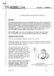
COMMUNICATION SYSTEM . . . . . . . . . . . . . . . . . . . . . . . . . . 23-1<br />
High Frequency (HF) Radio Systems . . . . . . . . . . . . . . . . . . . . . 23-2<br />
Very High Frequency (VHF) Radio Systems . . . . . . . . . . . . . . . . 23-11<br />
Multiple Radio Transmit Installation . . . . . . . . . . . . . . . . . . . . . 23-17<br />
Ultra High Frequency (UHF) Radio Systems . . . . . . . . . . . . . . . . 23-19<br />
Interphone and Public Address (PA) Systems . . . . . . . . . . . . . . . . 23-26<br />
Static Discharging System . . . . . . . . . . . . . . . . . . . . . . . . . . 23-36<br />
Joint Airborne Communication Center/Command Post (JACC/CP) . . . . . 23-37<br />
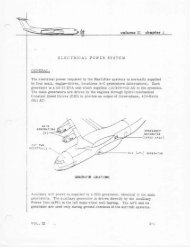
ELECTRICAL SYSTEM . . . . . . . . . . . . . . . . . . . . . . . . . . . . . 24-1<br />
Generator Drive System . . . . . . . . . . . . . . . . . . . . . . . . . . . . 24-2<br />
iv
Alternating Current (AC) Generation System . . . . . . . . . . . . . . . . . 24-18<br />
Direct Current (DC) Generation System . . . . . . . . . . . . . . . . . . . 24-54<br />
External Power System . . . . . . . . . . . . . . . . . . . . . . . . . . . . 24-61<br />
Emergency Generation System . . . . . . . . . . . . . . . . . . . . . . . . 24-67<br />
EQUIPMENT AND FURNISHINGS . . . . . . . . . . . . . . . . . . . . . . . 25-1<br />
Flight Station Equipment . . . . . . . . . . . . . . . . . . . . . . . . . . . 25-2<br />
Galley . . . . . . . . . . . . . . . . . . . . . . . . . . . . . . . . . . . . . 25-8<br />
Lavatory . . . . . . . . . . . . . . . . . . . . . . . . . . . . . . . . . . . . 25-9<br />
Cargo Compartment Equipment (Floor and Walkways) . . . . . . . . . . 25-10<br />
Emergency Equipment . . . . . . . . . . . . . . . . . . . . . . . . . . . . 25-17<br />
Aerial Delivery System (ADS) and Related Components . . . . . . . . . . 25-22<br />
Special Missions Equipment . . . . . . . . . . . . . . . . . . . . . . . . . 25-30<br />
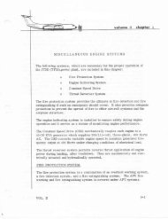
FIRE PROTECTION SYSTEM . . . . . . . . . . . . . . . . . . . . . . . . . 26-1<br />
Detection and Warning Systems . . . . . . . . . . . . . . . . . . . . . . . 26-1<br />
Fire Extinguishing Systems . . . . . . . . . . . . . . . . . . . . . . . . . . 26-12<br />
FLIGHT CONTROL SYSTEM . . . . . . . . . . . . . . . . . . . . . . . . . . 27-1<br />
Aileron Subsystem . . . . . . . . . . . . . . . . . . . . . . . . . . . . . . 27-5<br />
Rudder Subsystem . . . . . . . . . . . . . . . . . . . . . . . . . . . . . . 27-12<br />
Elevator Subsystem . . . . . . . . . . . . . . . . . . . . . . . . . . . . . . 27-18<br />
Pitch Trim Subsystem . . . . . . . . . . . . . . . . . . . . . . . . . . . . . 27-32<br />
Flaps Subsystem . . . . . . . . . . . . . . . . . . . . . . . . . . . . . . . 27-38<br />
Spoilers Subsystem . . . . . . . . . . . . . . . . . . . . . . . . . . . . . . 27-48<br />
FUEL SYSTEM . . . . . . . . . . . . . . . . . . . . . . . . . . . . . . . . . 28-1<br />
Storage Subsystem . . . . . . . . . . . . . . . . . . . . . . . . . . . . . . 28-1<br />
Distribution Subsystem . . . . . . . . . . . . . . . . . . . . . . . . . . . . 28-11<br />
Jettison Subsystem . . . . . . . . . . . . . . . . . . . . . . . . . . . . . . 28-32<br />
Indication and Warning Subsystem . . . . . . . . . . . . . . . . . . . . . . 28-36<br />
HYDRAULIC POWER SYSTEMS . . . . . . . . . . . . . . . . . . . . . . . 29-1<br />
Hydraulic System No. 1 . . . . . . . . . . . . . . . . . . . . . . . . . . . . 29-2<br />
v
Hydraulic System No.2 . . . . . . . . . . . . . . . . . . . . . . . . . . . . . 29-8<br />
Hydraulic System No.3 . . . . . . . . . . . . . . . . . . . . . . . . . . . . 29-15<br />
ICE AND RAIN PROTECTION SYSTEM . . . . . . . . . . . . . . . . . . . . 30-1<br />
Wing Anti-Ice and Empennage De-Ice Subsystem . . . . . . . . . . . . . . 30-1<br />
Pitot-Static Tubes Anti-Ice Subsystem . . . . . . . . . . . . . . . . . . . . . 30-7<br />
Windshield Anti-Ice and Rain Removal Subsystem . . . . . . . . . . . . . . 30-8<br />
Ice Detection Subsystem . . . . . . . . . . . . . . . . . . . . . . . . . . 30-17<br />
Engine Pressure Ratio (EPR) Probe Anti-Ice Subsystem . . . . . . . . . . 30-19<br />
INDICATING AND RECORDING SYSTEM . . . . . . . . . . . . . . . . . . . 31-1<br />
Cockpit Voice Recorder (CVR) System . . . . . . . . . . . . . . . . . . . . 31-4<br />
Digital Flight Data Recorder (DFDR) System . . . . . . . . . . . . . . . . . 31-9<br />
Life History Recorder System (LHRS) . . . . . . . . . . . . . . . . . . . . 31-14<br />
Takeoff Warning System . . . . . . . . . . . . . . . . . . . . . . . . . . . 31-20<br />
LANDING GEAR SYSTEM . . . . . . . . . . . . . . . . . . . . . . . . . . . 32-1<br />
Main Landing Gear (MLG) and Doors Subsystem . . . . . . . . . . . . . . . 32-7<br />
Nose Landing Gear (NLG) and Doors Subsystem . . . . . . . . . . . . . 32-14<br />
Extension and Retraction Subsystem . . . . . . . . . . . . . . . . . . . . 32-19<br />
Main Landing Gear (MLG) Brakes and Anti-Skid Subsystem . . . . . . . . 32-31<br />
Nose Landing Gear (NLG) Steering Subsystem . . . . . . . . . . . . . . . 32-40<br />
Landing Gear Position and Warning Subsystem . . . . . . . . . . . . . . 32-46<br />
LIGHTING SYSTEM . . . . . . . . . . . . . . . . . . . . . . . . . . . . . . . 33-1<br />
Flight Station Lighting Subsystem . . . . . . . . . . . . . . . . . . . . . . . 33-1<br />
Cargo and Service Compartment Lighting Subsystem . . . . . . . . . . . . 33-6<br />
Exterior Lighting Subsystem . . . . . . . . . . . . . . . . . . . . . . . . . 33-15<br />
Emergency Lighting Subsystem . . . . . . . . . . . . . . . . . . . . . . . 33-18<br />
NAVIGATION SYSTEM . . . . . . . . . . . . . . . . . . . . . . . . . . . . . 34-1<br />
Pitot-Static System . . . . . . . . . . . . . . . . . . . . . . . . . . . . . . . 34-1<br />
Central Air Data Computer (CADC) System . . . . . . . . . . . . . . . . . . 34-6<br />
Total Air Temperature (TAT) System . . . . . . . . . . . . . . . . . . . . 34-11<br />
vi
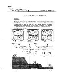
Radar Altimeter System . . . . . . . . . . . . . . . . . . . . . . . . . . . . 34-13<br />
Attitude and Heading Reference System (AHRS) . . . . . . . . . . . . . 34-17<br />
Flight Director System . . . . . . . . . . . . . . . . . . . . . . . . . . . . 34-23<br />
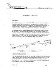
Glideslope (G/S) System . . . . . . . . . . . . . . . . . . . . . . . . . . . 34-39<br />
Marker Beacon System . . . . . . . . . . . . . . . . . . . . . . . . . . . . 34-43<br />
Identification Friend or Foe (IFF) System . . . . . . . . . . . . . . . . . . . 34-47<br />
Weather Radar System . . . . . . . . . . . . . . . . . . . . . . . . . . . . 34-53<br />
Ground Proximity Warning System (GPWS) . . . . . . . . . . . . . . . . . 34-66<br />
Inertial Navigation System (INS) . . . . . . . . . . . . . . . . . . . . . . . 34-69<br />
Automatic Direction Finder (ADF) System . . . . . . . . . . . . . . . . . . 34-86<br />
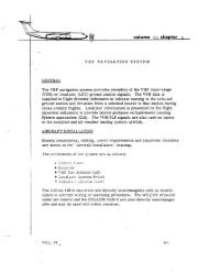
Very High Frequency (VHF) Navigation System . . . . . . . . . . . . . . 34-91<br />
Tactical Air Navigation (TACAN) System . . . . . . . . . . . . . . . . . . 34-104<br />
Intraformation Positioning System (SKE) . . . . . . . . . . . . . . . . . . 34-112<br />
Fuel Savings Advisory System (FSAS) . . . . . . . . . . . . . . . . . . . 34-122<br />
Standby Attitude Indicator (AI) . . . . . . . . . . . . . . . . . . . . . . . 34-132<br />
OXYGEN SYSTEM . . . . . . . . . . . . . . . . . . . . . . . . . . . . . . . 35-1<br />
Crew Oxygen System . . . . . . . . . . . . . . . . . . . . . . . . . . . . . 35-4<br />
Troop Oxygen System . . . . . . . . . . . . . . . . . . . . . . . . . . . . 35-13<br />
Portable Oxygen Bottles . . . . . . . . . . . . . . . . . . . . . . . . . . . 35-19<br />
AUXILIARY POWER UNIT (APU) SYSTEM . . . . . . . . . . . . . . . . . . 49-1<br />
Engine Subsystem . . . . . . . . . . . . . . . . . . . . . . . . . . . . . . 49-1<br />
Engine Fuel Control Subsystem . . . . . . . . . . . . . . . . . . . . . . . 49-6<br />
Starting/Ignition Subsystem . . . . . . . . . . . . . . . . . . . . . . . . . . 49-11<br />
Bleed Air Subsystem . . . . . . . . . . . . . . . . . . . . . . . . . . . . . 49-15<br />
Control Subsystem . . . . . . . . . . . . . . . . . . . . . . . . . . . . . . 49-17<br />
Oil Subsystem . . . . . . . . . . . . . . . . . . . . . . . . . . . . . . . . . 49-19<br />
STRUCTURES . . . . . . . . . . . . . . . . . . . . . . . . . . . . . . . . . 51-1<br />
STRUCTURAL DOORS SYSTEM . . . . . . . . . . . . . . . . . . . . . . . 52-1<br />
Crew and Troop Doors Subsystem . . . . . . . . . . . . . . . . . . . . . . 52-1<br />
vii
Emergency Exits Subsystem . . . . . . . . . . . . . . . . . . . . . . . . . 52-4<br />
Cargo Doors Subsystem . . . . . . . . . . . . . . . . . . . . . . . . . . . 52-11<br />
Interior Doors Subsystem . . . . . . . . . . . . . . . . . . . . . . . . . . 52-33<br />
Door Warning Subsystem . . . . . . . . . . . . . . . . . . . . . . . . . . 52-34<br />
WINDOWS . . . . . . . . . . . . . . . . . . . . . . . . . . . . . . . . . . . . 56-1<br />
Windshield Inspection . . . . . . . . . . . . . . . . . . . . . . . . . . . . . 56-1<br />
Windshield Heating System . . . . . . . . . . . . . . . . . . . . . . . . . . 56-2<br />
STANDARD PRACTICES (ENGINE) . . . . . . . . . . . . . . . . . . . . . . 70-1<br />
POWER PLANT (GENERAL) . . . . . . . . . . . . . . . . . . . . . . . . . . 71-1<br />
ENGINE FUEL AND IGNITION SYSTEM . . . . . . . . . . . . . . . . . . . . 73-1<br />
Fuel System . . . . . . . . . . . . . . . . . . . . . . . . . . . . . . . . . . 73-2<br />
Ignition System . . . . . . . . . . . . . . . . . . . . . . . . . . . . . . . . . 73-8<br />
ENGINE AIR SYSTEM . . . . . . . . . . . . . . . . . . . . . . . . . . . . . . 75-1<br />
System Operation . . . . . . . . . . . . . . . . . . . . . . . . . . . . . . . 75-1<br />
ENGINE CONTROLS SYSTEM . . . . . . . . . . . . . . . . . . . . . . . . . 76-1<br />
Controls System Operation . . . . . . . . . . . . . . . . . . . . . . . . . . 76-1<br />
ENGINE INSTRUMENT SYSTEM . . . . . . . . . . . . . . . . . . . . . . . . 77-1<br />
Engine System Operation . . . . . . . . . . . . . . . . . . . . . . . . . . . 77-1<br />
Engine Indicators . . . . . . . . . . . . . . . . . . . . . . . . . . . . . . . 77-1<br />
Engine Data Converter (EDC) . . . . . . . . . . . . . . . . . . . . . . . . . 77-3<br />
Engine Pressure Ratio (EPR) System . . . . . . . . . . . . . . . . . . . . . 77-4<br />
Revolutions Per Minute (RPM) System . . . . . . . . . . . . . . . . . . . . 77-7<br />
Exhaust Gas Temperature (EGT) System . . . . . . . . . . . . . . . . . . . 77-8<br />
Engine Vibration Indicating (EVI) System . . . . . . . . . . . . . . . . . . . 77-9<br />
ENGINE EXHAUST SYSTEM . . . . . . . . . . . . . . . . . . . . . . . . . . 78-1<br />
Exhaust System Operation . . . . . . . . . . . . . . . . . . . . . . . . . . 78-1<br />
Thrust Reverser (TR) System Components . . . . . . . . . . . . . . . . . . 78-2<br />
Thrust Reverser (TR) Operation . . . . . . . . . . . . . . . . . . . . . . . . 78-2<br />
ENGINE OIL SYSTEM . . . . . . . . . . . . . . . . . . . . . . . . . . . . . . 79-1<br />
viii
Oil System Operation . . . . . . . . . . . . . . . . . . . . . . . . . . . . . 79-1<br />
Oil System Pressure Components . . . . . . . . . . . . . . . . . . . . . . 79-2<br />
Oil System Scavenge Components . . . . . . . . . . . . . . . . . . . . . . 79-3<br />
Oil Breather System . . . . . . . . . . . . . . . . . . . . . . . . . . . . . . 79-4<br />
Oil System Indication Components . . . . . . . . . . . . . . . . . . . . . . 79-4<br />
ENGINE STARTING SYSTEM . . . . . . . . . . . . . . . . . . . . . . . . . 80-1<br />
Starting System Components and Operation . . . . . . . . . . . . . . . . . 80-1<br />
GLOSSARY OF ABBREVIATIONS/ACRONYMS . . . . . . . . . . . . . . . . A-1<br />
ix
NOTES<br />
x
C-<strong>141</strong>B <strong>Handbook</strong><br />
C-<strong>141</strong>B TECHNICAL ORDERS<br />
T.O. NUMBER<br />
T.O. TITLE<br />
1C-<strong>141</strong>B-01 . . . . . . . . . . . . . . . . . . . . . . . . . List of Applicable Publications<br />
1C-<strong>141</strong>B-06 . . . . . . . . . . . . . . . . . . . . . . . . . Aircraft Maintenance - Work Unit<br />
Code Manual<br />
1C-<strong>141</strong>B-1 . . . . . . . . . . . . . . . . . . . . . . . . . . Flight Manual<br />
1C-<strong>141</strong>B-1-1. . . . . . . . . . . . . . . . . . . . . . . . . Flight Manual - Appendix 1 -<br />
Performance Data<br />
1C-<strong>141</strong>B-1CL-1 . . . . . . . . . . . . . . . . . . . . . . Pilot’s, Flight Crew Checklist<br />
1C-<strong>141</strong>B-1CL-1-1. . . . . . . . . . . . . . . . . . . . . Pilot’s, Scroll Checklist<br />
1C-<strong>141</strong>B-1CL-2 . . . . . . . . . . . . . . . . . . . . . . Flight Engineer’s, Flight Crew<br />
Checklist<br />
1C-<strong>141</strong>B-1CL-2-1. . . . . . . . . . . . . . . . . . . . . Flight Engineer’s, Scroll Checklist<br />
1C-<strong>141</strong>B-1CL-3 . . . . . . . . . . . . . . . . . . . . . . Navigator’s, Flight Crew Checklist<br />
1C-<strong>141</strong>B-1CL-4 . . . . . . . . . . . . . . . . . . . . . . Loadmaster’s, Flight Crew Checklist<br />
1C-<strong>141</strong>B-1CL-5 . . . . . . . . . . . . . . . . . . . . . . Scanner’s, Flight Crew Checklist<br />
1C-<strong>141</strong>B-1CL-6 . . . . . . . . . . . . . . . . . . . . . . Medical Crew Director/Flight<br />
Nurses/Medical Technicians, Flight<br />
Crew Checklist<br />
1C-<strong>141</strong>B-2-1. . . . . . . . . . . . . . . . . . . . . . . . . Cross Servicing Guide<br />
1C-<strong>141</strong>B-2-3JG-1. . . . . . . . . . . . . . . . . . . . . Organizational Maintenance - Job<br />
Guide - Pneudraulic, Hydraulic<br />
Systems No.1 and No.2<br />
1C-<strong>141</strong>B-2-3JG-3-1 . . . . . . . . . . . . . . . . . . . Organizational Maintenance - Job<br />
Guide - Pneudraulics, Flight<br />
Controls, and Anti-Icing System<br />
(Vol 1)<br />
1C-<strong>141</strong>B-2-4JG-2. . . . . . . . . . . . . . . . . . . . . Organizational Maintenance - Job<br />
Guide Power Plant, Engine<br />
1C-<strong>141</strong>B-2-4JG-3. . . . . . . . . . . . . . . . . . . . . Organizational Maintenance - Job<br />
Guide - Power Plant, Engine Oil,<br />
and Compressor Bleed Air System<br />
1C-<strong>141</strong>B-2-4JG-8. . . . . . . . . . . . . . . . . . . . . Organizational Maintenance - Job<br />
Guide - Power Plant, Auxiliary<br />
Power Unit (APU)<br />
1C-<strong>141</strong>B-2-7JG-2. . . . . . . . . . . . . . . . . . . . . Organizational Maintenance - Job<br />
Guide - Electrical System, Landing<br />
Gear System<br />
xi
C-<strong>141</strong>B Aircraft Technical Orders<br />
T.O. NUMBER<br />
T.O. TITLE<br />
1C-<strong>141</strong>B-2-7JG-3 . . . . . . . . . . . . . . . . . . . . . Organizational Maintenance - Job<br />
Guide - Electric System, Brakes,<br />
Flight Controls, and Engine Systems<br />
1C-<strong>141</strong>B-2-7TS-1 . . . . . . . . . . . . . . . . . . . . . Troubleshooting - Electrical<br />
1C-<strong>141</strong>B-2-8JG-3 . . . . . . . . . . . . . . . . . . . . . Organizational Maintenance - Job<br />
Guide - Navigational System<br />
1C-<strong>141</strong>B-2-00FR-00-1 . . . . . . . . . . . . . . . . . Organizational Maintenance - Fault<br />
Reporting<br />
1C-<strong>141</strong>B-2-00GE-00-1 . . . . . . . . . . . . . . . . . Organizational Maintenance -<br />
General Equipment<br />
1C-<strong>141</strong>B-2-00JG-00-1 . . . . . . . . . . . . . . . . . Organizational Maintenance - Job<br />
Guide - Index<br />
1C-<strong>141</strong>B-2-05JG-00-1 . . . . . . . . . . . . . . . . . Organizational Maintenance - Job<br />
Guide - Ground Handling, General<br />
Maintenance<br />
1C-<strong>141</strong>B-2-07JG-00-1 . . . . . . . . . . . . . . . . . Organizational Maintenance - Job<br />
Guide - Ground Handling, Jacking<br />
1C-<strong>141</strong>B-2-08JG-00-1 . . . . . . . . . . . . . . . . . Organizational Maintenance - Job<br />
Guide - Ground Handling, Leveling,<br />
and Weighing<br />
1C-<strong>141</strong>B-2-09JG-00-1 . . . . . . . . . . . . . . . . . Organizational Maintenance - Job<br />
Guide - Ground Handling, Towing<br />
1C-<strong>141</strong>B-2-10JG-00-1 . . . . . . . . . . . . . . . . . Organizational Maintenance - Job<br />
Guide - Ground Handling, Parking,<br />
and Mooring<br />
1C-<strong>141</strong>B-2-11WD-1-1. . . . . . . . . . . . . . . . . . Organizational Maintenance -<br />
Aircraft Wiring Diagrams<br />
1C-<strong>141</strong>B-2-11WD-1-2. . . . . . . . . . . . . . . . . . Organizational Maintenance -<br />
Aircraft Wiring Diagrams<br />
SERVICING<br />
1C-<strong>141</strong>B-2-12JG-10-1 . . . . . . . . . . . . . . . . . Organizational Maintenance - Job<br />
Guide - Ground Handling, Servicing<br />
1C-<strong>141</strong>B-2-12JG-10-2 . . . . . . . . . . . . . . . . . Organizational Maintenance - Job<br />
Guide - Concurrent Servicing and<br />
Ground Handling, Quick Turn<br />
1C-<strong>141</strong>B-2-12JG-20-1 . . . . . . . . . . . . . . . . . Organizational Maintenance - Job<br />
Guide - Ground Handling,<br />
Lubrication<br />
xii
C-<strong>141</strong>B <strong>Handbook</strong><br />
T.O. NUMBER<br />
T.O. TITLE<br />
AIR CONDITIONING<br />
1C-<strong>141</strong>B-2-21FI-00-1 . . . . . . . . . . . . . . . . . . Organizational Maintenance - Fault<br />
Isolation - Air Conditioning System<br />
Equipment Cooling, Bleed Air and<br />
Pressurization, Fault Codes:<br />
2100A01, 2100A02, 2100001<br />
through 2100999, 2110A01,<br />
2110A02, 2110001 through<br />
2110999, 2130A01, and 2130001<br />
through 2130999<br />
1C-<strong>141</strong>B-2-21FI-00-2 . . . . . . . . . . . . . . . . . . Organizational Maintenance - Fault<br />
Isolation - Air Conditioning System,<br />
Floor Heat and Temperature, and<br />
Flow Control, Fault Codes:<br />
2150A01, 2150A02, 2150001<br />
through 2150999, 2160A01, and<br />
2160001 through 2160999<br />
1C-<strong>141</strong>B-2-21GS-00-1 . . . . . . . . . . . . . . . . . Organizational Maintenance -<br />
General System - Air Conditioning<br />
System<br />
1C-<strong>141</strong>B-2-21JG-00-1 . . . . . . . . . . . . . . . . . Organizational Maintenance - Job<br />
Guide - Air Conditioning, General<br />
Maintenance<br />
1C-<strong>141</strong>B-2-21JG-10-1 . . . . . . . . . . . . . . . . . Organizational Maintenance - Job<br />
Guide - Air Conditioning Bleed Air<br />
1C-<strong>141</strong>B-2-21JG-10-2 . . . . . . . . . . . . . . . . . Organizational Maintenance - Job<br />
Guide - Air Conditioning Bleed Air<br />
1C-<strong>141</strong>B-2-21JG-30-1 . . . . . . . . . . . . . . . . . Organizational Maintenance - Job<br />
Guide - Air Conditioning<br />
Pressurization<br />
1C-<strong>141</strong>B-2-21JG-50-1 . . . . . . . . . . . . . . . . . Organizational Maintenance - Job<br />
Guide - Air Conditioning Heating<br />
and Cooling<br />
1C-<strong>141</strong>B-2-21JG-60-1 . . . . . . . . . . . . . . . . . Organizational Maintenance - Job<br />
Guide - Air Conditioning<br />
Temperature Control<br />
AUTO FLIGHT<br />
1C-<strong>141</strong>B-2-22FI -00-1-1. . . . . . . . . . . . . . . . Organizational Maintenance - Fault<br />
Isolation - Automatic Flight Control<br />
System (AFCS) Yaw Damper, Fault<br />
Codes: 2210001 through 2210199,<br />
and 2210Y01<br />
xiii
C-<strong>141</strong>B Aircraft Technical Orders<br />
T.O. NUMBER<br />
T.O. TITLE<br />
1C-<strong>141</strong>B-2-22FI-00-1-2 . . . . . . . . . . . . . . . . Organizational Maintenance - Fault<br />
Isolation - Automatic Flight Control<br />
System (AFCS) - Basic and<br />
Extended Autopilot (A/P), Fault<br />
Codes: 2210201 through 2210999,<br />
2210A01, 2210B01, 2210C01,<br />
2210L01, 2210M01, 2210N01,<br />
2210P01, and 2210S01<br />
1C-<strong>141</strong>B-2-22FI-00-2 . . . . . . . . . . . . . . . . . . Organizational Maintenance - Fault<br />
Isolation - Automatic Flight Control<br />
System (AFCS) - Auto Throttle<br />
System (ATS), Fault Codes:<br />
2230001 through 2230999, and<br />
2230A01<br />
1C-<strong>141</strong>B-2-22FI-00-3 . . . . . . . . . . . . . . . . . . Organizational Maintenance - Fault<br />
Isolation - Automatic Flight Control<br />
System (AFCS) - All Weather<br />
Landing System (AWLS), Fault<br />
Codes: 2250001 through 2250999,<br />
and 2250A01<br />
1C-<strong>141</strong>B-2-22GS-00-1 . . . . . . . . . . . . . . . . . Organizational Maintenance -<br />
General System - Automatic Flight<br />
Control System (AFCS)<br />
1C-<strong>141</strong>B-2-22JG-10-1 . . . . . . . . . . . . . . . . . Organizational Maintenance - Job<br />
Guide - Automatic Flight Control<br />
System (AFCS), General<br />
Information, Yaw Damper (Y/D), and<br />
Autopilot (A/P) - C-<strong>141</strong>A/C-<strong>141</strong>B<br />
Aircraft<br />
1C-<strong>141</strong>B-2-22JG-20-1 . . . . . . . . . . . . . . . . . Organizational Maintenance - Job<br />
Guide - Automatic Flight Control<br />
System (AFCS), Mach Trim -<br />
C-<strong>141</strong>A/C-<strong>141</strong>B Aircraft<br />
1C-<strong>141</strong>B-2-22JG-30-1 . . . . . . . . . . . . . . . . . Organizational Maintenance - Job<br />
Guide - Automatic Flight Control<br />
System (AFCS), Auto Throttle<br />
System (ATS)<br />
1C-<strong>141</strong>B-2-22JG-50-1 . . . . . . . . . . . . . . . . . Organizational Maintenance - Job<br />
Guide - Automatic Flight Control<br />
System (AFCS), All Weather<br />
Landing System (AWLS)<br />
xiv
C-<strong>141</strong>B <strong>Handbook</strong><br />
T.O. NUMBER<br />
T.O. TITLE<br />
COMMUNICATIONS<br />
1C-<strong>141</strong>B-2-23FI-00-1-1 . . . . . . . . . . . . . . . . Organizational Maintenance - Fault<br />
Isolation - Communication System,<br />
High Frequency (HF), Very High<br />
Frequency (VHF), and Ultra High<br />
Frequency (UHF) Subsystems, and<br />
Multiple Radio Transmit Installation<br />
1C-<strong>141</strong>B-2-23FI-00-1-2 . . . . . . . . . . . . . . . . Organizational Maintenance - Fault<br />
Isolation - Communication System,<br />
Interphone and Public Address (PA)<br />
Subsystem, Fault Codes: 2340000<br />
through 2340999, 2340101, and<br />
2340P01<br />
1C-<strong>141</strong>B-2-23FI-00-1-3 . . . . . . . . . . . . . . . . Organizational Maintenance - Fault<br />
Isolation - Communication System -<br />
Joint Airborne Communication<br />
Center/Command Post (JACC/CP)<br />
Procedures<br />
1C-<strong>141</strong>B-2-23GS-00-1 . . . . . . . . . . . . . . . . . Organizational Maintenance -<br />
General System, Communications<br />
1C-<strong>141</strong>B-2-23JG-10-1 . . . . . . . . . . . . . . . . . Organizational Maintenance - Job<br />
Guide - Communication System -<br />
HF Subsystem<br />
1C-<strong>141</strong>B-2-23JG-20-1 . . . . . . . . . . . . . . . . . Organizational Maintenance - Job<br />
Guide - Communication System,<br />
VHF/UHF Subsystems, and Multiple<br />
Radio Transmitter Installation<br />
1C-<strong>141</strong>B-2-23JG-40-1 . . . . . . . . . . . . . . . . . Organizational Maintenance - Job<br />
Guide - Communication System,<br />
Interphone Subsystem<br />
1C-<strong>141</strong>B-2-23JG-60-1 . . . . . . . . . . . . . . . . . Organizational Maintenance - Job<br />
Guide - Communication System,<br />
Static Discharge Subsystem<br />
1C-<strong>141</strong>B-2-23JG-80-1 . . . . . . . . . . . . . . . . . Organizational Maintenance - Job<br />
Guide - Communication System,<br />
JACC/CP Procedures<br />
xv
C-<strong>141</strong>B Aircraft Technical Orders<br />
T.O. NUMBER<br />
T.O. TITLE<br />
ELECTRICAL POWER<br />
1C-<strong>141</strong>B-2-24FI-00-1 . . . . . . . . . . . . . . . . . . Organizational Maintenance - Fault<br />
Isolation - Electrical System -<br />
Generator Drive, AC, DC, and<br />
Emergency Generation, and<br />
External Power, Fault Codes:<br />
2400001 through 2460999,<br />
2420A01, 2420B01, 2420C01,<br />
2430A01, 2430B01, 2440A01, and<br />
2460A01<br />
1C-<strong>141</strong>B-2-24GS-00-1 . . . . . . . . . . . . . . . . . Organizational Maintenance -<br />
General System - Electrical System<br />
1C-<strong>141</strong>B-2-24JG-10-1 . . . . . . . . . . . . . . . . . Organizational Maintenance - Job<br />
Guide - Electrical System, General<br />
Information and Generator Drive<br />
1C-<strong>141</strong>B-2-24JG-20-1 . . . . . . . . . . . . . . . . . Organizational Maintenance - Job<br />
Guide - Electrical System AC-DC<br />
Power Generation, External Power,<br />
and Emergency Generator<br />
EQUIPMENT & FURNISHINGS<br />
1C-<strong>141</strong>B-2-25FI-00-1 . . . . . . . . . . . . . . . . . . Organizational Maintenance - Fault<br />
Isolation, Equipment and<br />
Furnishings, Fault Codes: 2500000<br />
through 2580999, 2500S01,<br />
2540L01, 2560B01, 2560T11,<br />
2580A01, 2580E11, 2580E21,<br />
2580J31, 2580P41, and 2580L51<br />
1C-<strong>141</strong>B-2-25GS-00-1 . . . . . . . . . . . . . . . . . Organizational Maintenance -<br />
General System - Equipment and<br />
Furnishings<br />
1C-<strong>141</strong>B-2-25JG-00-1 . . . . . . . . . . . . . . . . . Organizational Maintenance - Job<br />
Guide - Equipment and Furnishings,<br />
General Maintenance<br />
1C-<strong>141</strong>B-2-25JG-10-1 . . . . . . . . . . . . . . . . . Organizational Maintenance - Job<br />
Guide - Equipment and Furnishings,<br />
Flight Station<br />
1C-<strong>141</strong>B-2-25JG-50-1 . . . . . . . . . . . . . . . . . Organizational Maintenance - Job<br />
Guide - Equipment and Furnishings,<br />
Cargo Compartment<br />
xvi
C-<strong>141</strong>B <strong>Handbook</strong><br />
T.O. NUMBER<br />
T.O. TITLE<br />
1C-<strong>141</strong>B-2-25JG-60-1 . . . . . . . . . . . . . . . . . Organizational Maintenance - Job<br />
Guide - Equipment and Furnishings,<br />
Emergency<br />
1C-<strong>141</strong>B-2-25JG-80-1 . . . . . . . . . . . . . . . . . Organizational Maintenance - Job<br />
Guide - Equipment and Furnishings,<br />
Aerial Delivery System (ADS)<br />
1C-<strong>141</strong>B-2-25JG-90-1 . . . . . . . . . . . . . . . . . Organizational Maintenance - Job<br />
Guide - Equipment and Furnishings,<br />
Alternate Mission Kits (AMK)<br />
FIRE PROTECTION<br />
1C-<strong>141</strong>B-2-26FI-00-1 . . . . . . . . . . . . . . . . . . Organizational Maintenance - Fault<br />
Isolation - Fire Protection System -<br />
Fault Codes: 2610000 through<br />
2620999, 2610E01, 2610A11,<br />
2610S21, 2620E01, and 2620A11<br />
1C-<strong>141</strong>B-2-26GS-00-1 . . . . . . . . . . . . . . . . . Organizational Maintenance -<br />
General System - Fire Protection<br />
System<br />
1C-<strong>141</strong>B-2-26JG-10-1 . . . . . . . . . . . . . . . . . Organizational Maintenance - Job<br />
Guide - Fire Protection System<br />
Detection, General Information, and<br />
Fire Detection<br />
1C-<strong>141</strong>B-2-26JG-20-1 . . . . . . . . . . . . . . . . . Organizational Maintenance - Job<br />
Guide - Fire Protection System<br />
Extinguishing<br />
FLIGHT CONTROLS<br />
1C-<strong>141</strong>B-2-27FI-00-1-1 . . . . . . . . . . . . . . . . Organizational Maintenance - Fault<br />
Isolation - Flight Controls, Ailerons,<br />
Rudder, Elevators, Stall Prevention<br />
Failures, Fault Codes: 2710000<br />
through 2733999, 2710AXX,<br />
2720RXX, 2730EXX, and 2733EXX<br />
1C-<strong>141</strong>B-2-27FI-00-1-2 . . . . . . . . . . . . . . . . Organizational Maintenance - Fault<br />
Isolation - Flight Controls, Pitch<br />
Trim, Flap, Spoilers Failures, Fault<br />
Codes: 2740000 through 2760999,<br />
2740PXX, 2750FXX, and 2760SXX<br />
1C-<strong>141</strong>B-2-27GS-00-1 . . . . . . . . . . . . . . . . . Organizational Maintenance -<br />
General System - Flight Controls<br />
xvii
C-<strong>141</strong>B Aircraft Technical Orders<br />
T.O. NUMBER<br />
T.O. TITLE<br />
1C-<strong>141</strong>B-2-27JG-00-1 . . . . . . . . . . . . . . . . . Organizational Maintenance - Job<br />
Guide - Flight Controls - General<br />
Maintenance<br />
1C-<strong>141</strong>B-2-27JG-10-1 . . . . . . . . . . . . . . . . . Organizational Maintenance - Job<br />
Guide - Flight Controls, Aileron Input<br />
System<br />
1C-<strong>141</strong>B-2-27JG-10-2 . . . . . . . . . . . . . . . . . Organizational Maintenance - Job<br />
Guide - Flight Controls, Aileron<br />
Output/Tab/Trim System<br />
1C-<strong>141</strong>B-2-27JG-20-1 . . . . . . . . . . . . . . . . . Organizational Maintenance - Job<br />
Guide - Flight Controls, Rudder<br />
Input System<br />
1C-<strong>141</strong>B-2-27JG-20-2 . . . . . . . . . . . . . . . . . Organizational Maintenance - Job<br />
Guide - Flight Controls, Rudder<br />
Output/Trim System<br />
1C-<strong>141</strong>B-2-27JG-30-1-1. . . . . . . . . . . . . . . . Organizational Maintenance - Job<br />
Guide - Flight Controls, Elevator<br />
Control System<br />
1C-<strong>141</strong>B-2-27JG-30-1-2. . . . . . . . . . . . . . . . Organizational Maintenance - Job<br />
Guide - Flight Controls, Elevator<br />
Control System<br />
1C-<strong>141</strong>B-2-27JG-30-2 . . . . . . . . . . . . . . . . . Organizational Maintenance - Job<br />
Guide - Flight Controls, Elevator<br />
Artificial Feel\Stall Prevention<br />
Systems<br />
1C-<strong>141</strong>B-2-27JG-40-1 . . . . . . . . . . . . . . . . . Organizational Maintenance - Job<br />
Guide - Flight Controls, Pitch Trim<br />
Mechanical-Hydraulic System<br />
1C-<strong>141</strong>B-2-27JG-40-2 . . . . . . . . . . . . . . . . . Organizational Maintenance - Job<br />
Guide - Flight Controls, Pitch Trim<br />
Electrical System<br />
1C-<strong>141</strong>B-2-27JG-50-1-1. . . . . . . . . . . . . . . . Organizational Maintenance - Job<br />
Guide - Flight Controls, Flaps<br />
Control System<br />
1C-<strong>141</strong>B-2-27JG-50-1-2. . . . . . . . . . . . . . . . Organizational Maintenance - Job<br />
Guide - Flight Controls, Flaps<br />
Control System<br />
1C-<strong>141</strong>B-2-27JG-50-2 . . . . . . . . . . . . . . . . . Organizational Maintenance - Job<br />
Guide - Flight Controls, Flaps<br />
Asymmetry System<br />
1C-<strong>141</strong>B-2-27JG-60-1 . . . . . . . . . . . . . . . . . Organizational Maintenance - Job<br />
Guide - Flight Controls, Spoilers<br />
Input System<br />
xviii
C-<strong>141</strong>B <strong>Handbook</strong><br />
T.O. NUMBER<br />
T.O. TITLE<br />
1C-<strong>141</strong>B-2-27JG-60-2-1 . . . . . . . . . . . . . . . Organizational Maintenance - Job<br />
Guide - Flight Controls, Spoilers<br />
Output/Asymmetry System<br />
1C-<strong>141</strong>B-2-27JG-60-2-2 . . . . . . . . . . . . . . . Organizational Maintenance - Job<br />
Guide - Flight Controls, Spoilers<br />
Output/Asymmetry System<br />
FUEL<br />
1C-<strong>141</strong>B-2-28FI-00-1-1 . . . . . . . . . . . . . . . . Organizational Maintenance - Fault<br />
Isolation - Fuel System - Ground<br />
and Aerial Refueling, Fault Codes:<br />
2821000 through 2822999,<br />
2821G01, 2821G11, 2821G21,<br />
2822A01, 2822A11, 2822A31, and<br />
2822A41<br />
1C-<strong>141</strong>B-2-28FI-00-1-2 . . . . . . . . . . . . . . . . Organizational Maintenance - Fault<br />
Isolation - Fuel System -<br />
Distribution, Fault Codes: 2823D01,<br />
2823D11, and 2823000 through<br />
2823999<br />
1C-<strong>141</strong>B-2-28FI-00-1-3 . . . . . . . . . . . . . . . . Organizational Maintenance - Fault<br />
Isolation - Fuel System - Jettison,<br />
Indicating and Quantity, Fault<br />
Codes: 2830J01, 2840Q11, and<br />
2840000 through 2840999<br />
1C-<strong>141</strong>B-2-28GS-00-1 . . . . . . . . . . . . . . . . . Organizational Maintenance -<br />
General System - Fuel System<br />
1C-<strong>141</strong>B-2-28JG-00-1 . . . . . . . . . . . . . . . . . Organizational Maintenance - Job<br />
Guide - Fuel System, General<br />
Maintenance<br />
1C-<strong>141</strong>B-2-28JG-10-1 . . . . . . . . . . . . . . . . . Organizational Maintenance - Job<br />
Guide - Fuel System, Storage<br />
1C-<strong>141</strong>B-2-28JG-20-1-1 . . . . . . . . . . . . . . . Organizational Maintenance - Job<br />
Guide - Fuel System, Ground and<br />
Aerial Refueling System<br />
1C-<strong>141</strong>B-2-28JG-20-1-2 . . . . . . . . . . . . . . . Organizational Maintenance - Job<br />
Guide - Fuel System, Distribution<br />
1C-<strong>141</strong>B-2-28JG-40-1 . . . . . . . . . . . . . . . . . Organizational Maintenance - Job<br />
Guide - Fuel System, Indication<br />
xix
C-<strong>141</strong>B Aircraft Technical Orders<br />
T.O. NUMBER<br />
T.O. TITLE<br />
HYDRAULIC POWER<br />
1C-<strong>141</strong>B-2-29FI-00-1 . . . . . . . . . . . . . . . . . . Organizational Maintenance -<br />
Hydraulic System, Fault Codes:<br />
2911A01, 2911000 through<br />
2911999, 2912A01, 2912000<br />
through 2912999, 2913A01, and<br />
2913000 through 2913999<br />
1C-<strong>141</strong>B-2-29GS-00-1 . . . . . . . . . . . . . . . . . Organizational Maintenance -<br />
General System - Hydraulic System<br />
1C-<strong>141</strong>B-2-29JG-10-1-1. . . . . . . . . . . . . . . . Organizational Maintenance - Job<br />
Guide - Hydraulic System<br />
1C-<strong>141</strong>B-2-29JG-10-1-2. . . . . . . . . . . . . . . . Organizational Maintenance - Job<br />
Guide - Hydraulic System<br />
ICE AND RAIN PROTECTION<br />
1C-<strong>141</strong>B-2-30FI-00-1 . . . . . . . . . . . . . . . . . . Organizational Maintenance - Fault<br />
Isolation - Ice and Rain Protection -<br />
Fault Codes: 301000 through<br />
3090999, 3010W01, 3010E11,<br />
3040W01, 3040R11, 3080W011,<br />
and 3090E01<br />
1C-<strong>141</strong>B-2-30GS-00-1 . . . . . . . . . . . . . . . . . Organizational Maintenance -<br />
General System - Ice and Rain<br />
Protection<br />
1C-<strong>141</strong>B-2-30JG-10-1 . . . . . . . . . . . . . . . . . Organizational Maintenance - Job<br />
Guide - Ice and Rain Protection -<br />
Wing Anti-Icing and Empennage<br />
Deicing System<br />
1C-<strong>141</strong>B-2-30JG-40-1 . . . . . . . . . . . . . . . . . Organizational Maintenance - Job<br />
Guide - Ice and Rain Protection -<br />
Window and Windshield Rain<br />
Removal and Anti-Icing Systems<br />
1C-<strong>141</strong>B-2-30JG-80-1 . . . . . . . . . . . . . . . . . Organizational Maintenance - Job<br />
Guide - Ice and Rain Protection - Ice<br />
Detection System<br />
1C-<strong>141</strong>B-2-30JG-90-1 . . . . . . . . . . . . . . . . . Organizational Maintenance - Job<br />
Guide - Ice and Rain Protection -<br />
Engine Deicing (Engine Pressure<br />
Ratio [EPR] Probe Heaters)<br />
xx
C-<strong>141</strong>B <strong>Handbook</strong><br />
T.O. NUMBER<br />
T.O. TITLE<br />
INDICATING AND RECORDING SYSTEM<br />
1C-<strong>141</strong>B-2-31FI-00-1 . . . . . . . . . . . . . . . . . . Organizational Maintenance - Fault<br />
Isolation - Indicating/Recording<br />
Systems - Fault Codes: 3131000<br />
through 3150999, 3131C01,<br />
3132F01, 3133L01, 3133T11, and<br />
3150T01<br />
1C-<strong>141</strong>B-2-31GS-00-1 . . . . . . . . . . . . . . . . . Organizational Maintenance -<br />
General System -<br />
Indicating/Recording System<br />
1C-<strong>141</strong>B-2-31JG-30-1 . . . . . . . . . . . . . . . . . Organizational Maintenance - Job<br />
Guide - Indicating/Recording<br />
Systems, Recorder System<br />
1C-<strong>141</strong>B-2-31JG-50-1 . . . . . . . . . . . . . . . . . Organizational Maintenance - Job<br />
Guide - Indicating/Recording<br />
Systems, Central Warning System<br />
LANDING GEAR<br />
1C-<strong>141</strong>B-2-32FI-00-1 . . . . . . . . . . . . . . . . . . Organizational Maintenance - Fault<br />
Isolation - Landing Gear System,<br />
Fault Codes: 3213000 through<br />
3260099<br />
1C-<strong>141</strong>B-2-32GS-00-1 . . . . . . . . . . . . . . . . . Organizational Maintenance -<br />
General System - Landing Gear<br />
1C-<strong>141</strong>B-2-32JG-00-1 . . . . . . . . . . . . . . . . . Organizational Maintenance - Job<br />
Guide - Landing Gear General<br />
Maintenance<br />
1C-<strong>141</strong>B-2-32JG-10-1 . . . . . . . . . . . . . . . . . Organizational Maintenance - Job<br />
Guide - Main Landing Gear (MLG)<br />
1C-<strong>141</strong>B-2-32JG-10-2 . . . . . . . . . . . . . . . . . Organizational Maintenance - Job<br />
Guide - Main Landing Gear (MLG)<br />
1C-<strong>141</strong>B-2-32JG-20-1 . . . . . . . . . . . . . . . . . Organizational Maintenance - Job<br />
Guide - Nose Landing Gear (NLG)<br />
1C-<strong>141</strong>B-2-32JG-20-2 . . . . . . . . . . . . . . . . . Organizational Maintenance - Job<br />
Guide - Nose Landing Gear (NLG)<br />
1C-<strong>141</strong>B-2-32JG-40-1 . . . . . . . . . . . . . . . . . Organizational Maintenance - Job<br />
Guide - Main Landing Gear (MLG)<br />
Brakes and Anti-skid Systems<br />
1C-<strong>141</strong>B-2-32JG-50-1 . . . . . . . . . . . . . . . . . Organizational Maintenance - Job<br />
Guide - Nose Landing Gear (NLG)<br />
Steering<br />
xxi
C-<strong>141</strong>B Aircraft Technical Orders<br />
T.O. NUMBER<br />
T.O. TITLE<br />
LIGHTS<br />
1C-<strong>141</strong>B-2-33FI-00-1-1 . . . . . . . . . . . . . . . . Technical Manual - Fault Isolation -<br />
Organizational Maintenance,<br />
General Lighting System<br />
1C-<strong>141</strong>B-2-33F-00-1-2 . . . . . . . . . . . . . . . . . Technical Manual - Fault Isolation -<br />
Organizational Maintenance,<br />
General Lighting System<br />
1C-<strong>141</strong>B-2-33FI-00-2 . . . . . . . . . . . . . . . . . . Technical Manual - Fault Isolation -<br />
Organizational Maintenance,<br />
General Lighting System<br />
1C-<strong>141</strong>B-2-33GS-00-1 . . . . . . . . . . . . . . . . . Organizational Maintenance -<br />
General System, Lighting System<br />
1C-<strong>141</strong>B-2-33JG-10-1 . . . . . . . . . . . . . . . . . Organizational Maintenance - Job<br />
Guide - Lighting System, Flight<br />
Station Lighting<br />
1C-<strong>141</strong>B-2-33JG-30-1 . . . . . . . . . . . . . . . . . Organizational Maintenance - Job<br />
Guide - Lighting System - Cargo<br />
and Service Compartment Lighting<br />
1C-<strong>141</strong>B-2-33JG-40-1 . . . . . . . . . . . . . . . . . Organizational Maintenance - Job<br />
Guide - Lighting System - Exterior<br />
Lighting<br />
1C-<strong>141</strong>B-2-33JG-50-1 . . . . . . . . . . . . . . . . . Organizational Maintenance - Job<br />
Guide - Lighting System -<br />
Emergency Lighting<br />
NAVIGATION<br />
1C-<strong>141</strong>B-2-34FI-00-1-1 . . . . . . . . . . . . . . . . Organizational Maintenance - Fault<br />
Isolation, Navigation (NAV) System<br />
- General Information and<br />
Pitot-Static, Central Air Data<br />
Computer (CADC), Total Air<br />
Temperature (TAT) and Radar<br />
Altimeter System, Fault Codes:<br />
3410001 through 3410999,<br />
3413001, 3413999, 3414001<br />
through 3414999, 3410001,<br />
3410002, 3413T01, 3414R01, and<br />
3414R02<br />
xxii
C-<strong>141</strong>B <strong>Handbook</strong><br />
T.O. NUMBER<br />
T.O. TITLE<br />
1C-<strong>141</strong>B-2-34FI-00-1-2 . . . . . . . . . . . . . . . . Organizational Maintenance - Fault<br />
Isolation, Navigation System -<br />
Attitude Heading Reference, Flight<br />
Director, Glideslope, and Marker<br />
Beacon System, Fault Codes:<br />
3421001 through 3421015,<br />
3421A01, 3422001 through<br />
3422027, 3422F01, 3431001<br />
through 3431006, 3431G01,<br />
3432001 through 3432014, and<br />
3432M01<br />
1C-<strong>141</strong>B-2-34FI-00-1-3 . . . . . . . . . . . . . . . . Organizational Maintenance - Fault<br />
Isolation, Navigation System -<br />
Identification Friend or Foe (IFF),<br />
Weather Radar, and Ground<br />
Proximity System<br />
1C-<strong>141</strong>B-2-34FI-00-1-4 . . . . . . . . . . . . . . . . Organizational Maintenance - Fault<br />
Isolation, Navigation System, Inertial<br />
Navigation System (INS), Fault<br />
Codes: 3444001 through 3444029,<br />
and 3444101<br />
1C-<strong>141</strong>B-2-34FI-00-1-5 . . . . . . . . . . . . . . . . Organizational Maintenance - Fault<br />
Isolation, Navigation System, Auto<br />
Directional Finder (ADF), VHF,<br />
NAV, and Tactical Air Navigation<br />
(TACAN) System, Fault Codes:<br />
3451000 through 3453999,<br />
3451A01, 3451A02, 3452V01,<br />
3452V02, 3453T01, and 3453T02,<br />
1C-<strong>141</strong>B-2-34FI-00-1-6 . . . . . . . . . . . . . . . . Organizational Maintenance - Fault<br />
Isolation, Navigation System,<br />
Intraformation Positioning System<br />
(Station Keeping Equipment [SKE]),<br />
Fault Codes: 3460001 through<br />
3460014, and 3460S01<br />
1C-<strong>141</strong>B-2-34FI-00-1-7 . . . . . . . . . . . . . . . . Organizational Maintenance - Fault<br />
Isolation, Navigation System, Fuel<br />
Savings Advisory System (FSAS),<br />
Fault Codes: 3470001 through<br />
3470024, and 3470F01<br />
1C-<strong>141</strong>B-2-34GS-00-1 . . . . . . . . . . . . . . . . . Organizational Maintenance -<br />
General System, Navigation System<br />
xxiii
C-<strong>141</strong>B Aircraft Technical Orders<br />
T.O. NUMBER<br />
T.O. TITLE<br />
1C-<strong>141</strong>B-2-34JG-00-1 . . . . . . . . . . . . . . . . . Organizational Maintenance - Job<br />
Guide - Navigation System, General<br />
Maintenance<br />
1C-<strong>141</strong>B-2-34JG-10-1 . . . . . . . . . . . . . . . . . Organizational Maintenance - Job<br />
Guide - Navigation System<br />
Pitot-Static, Central Air Data<br />
Computer, Total Air Temperature,<br />
and Radar Altimeter Systems<br />
1C-<strong>141</strong>B-2-34JG-20-1 . . . . . . . . . . . . . . . . . Organizational Maintenance - Job<br />
Guide - Navigation System, Attitude<br />
Heading Reference and Flight<br />
Director Systems<br />
1C-<strong>141</strong>B-2-34JG-30-1 . . . . . . . . . . . . . . . . . Organizational Maintenance - Job<br />
Guide - Navigation System,<br />
Glideslope and Marker Beacon<br />
Systems<br />
1C-<strong>141</strong>B-2-34JG-40-1-1. . . . . . . . . . . . . . . . Organizational Maintenance - Job<br />
Guide - Navigation, IFF, Weather<br />
Radar, and Ground Proximity<br />
Warning System<br />
1C-<strong>141</strong>B-2-34JG-40-1-2. . . . . . . . . . . . . . . . Organizational Maintenance - Job<br />
Guide - Navigation System, Inertial<br />
Navigation System<br />
1C-<strong>141</strong>B-2-34JG-50-1 . . . . . . . . . . . . . . . . . Organizational Maintenance - Job<br />
Guide - Navigation System,<br />
Automatic Direction Finding, VHF<br />
Navigation, and TACAN System<br />
1C-<strong>141</strong>B-2-34JG-60-1 . . . . . . . . . . . . . . . . . Organizational Maintenance - Job<br />
Guide - Navigation System,<br />
Intraformation Positioning (Station<br />
Keeping Equipment) System<br />
1C-<strong>141</strong>B-2-34JG-70-1 . . . . . . . . . . . . . . . . . Organizational Maintenance - Job<br />
Guide - Navigation System, Fuel<br />
Savings Advisory System (FSAS)<br />
OXYGEN<br />
1C-<strong>141</strong>B-2-35FI-00-1 . . . . . . . . . . . . . . . . . . Organizational Maintenance - Fault<br />
Isolation, Oxygen System - Fault<br />
Codes: 3510000 through 3520999<br />
1C-<strong>141</strong>B-2-35GS-00-1 . . . . . . . . . . . . . . . . . Organizational Maintenance -<br />
General System, Oxygen System<br />
xxiv
C-<strong>141</strong>B <strong>Handbook</strong><br />
T.O. NUMBER<br />
T.O. TITLE<br />
1C-<strong>141</strong>B-2-35JG-00-1 . . . . . . . . . . . . . . . . . Organizational Maintenance - Job<br />
Guide - Oxygen System, General<br />
Maintenance<br />
1C-<strong>141</strong>B-2-35JG-10-1 . . . . . . . . . . . . . . . . . Organizational Maintenance - Job<br />
Guide - Oxygen System, Crew<br />
Oxygen<br />
1C-<strong>141</strong>B-2-35JG-20-1 . . . . . . . . . . . . . . . . . Organizational Maintenance - Job<br />
Guide - Oxygen System, Troop<br />
Oxygen<br />
SYSTEMS INTEGRATION AND DISPLAY<br />
1C-<strong>141</strong>B-2-46FI-00-1 . . . . . . . . . . . . . . . . . . Organizational Maintenance - Fault<br />
Isolation - Integration and Display -<br />
Selected C-<strong>141</strong>B Aircraft<br />
1C-<strong>141</strong>B-2-46GS-00-1 . . . . . . . . . . . . . . . . . Organizational Maintenance -<br />
General System - System<br />
Integration and Display - Selected<br />
C-<strong>141</strong>B Aircraft<br />
1C-<strong>141</strong>B-2-46JG-20-1 . . . . . . . . . . . . . . . . . Organizational Maintenance - Job<br />
Guide - Systems Integration and<br />
Display Processing and integration,<br />
AN/ASN-159 Integrated Sensor<br />
Display System (ISDS), Selected<br />
C-<strong>141</strong>B Aircraft<br />
AUXILIARY POWER<br />
1C-<strong>141</strong>B-2-49-FI-00-1 . . . . . . . . . . . . . . . . . Organizational Maintenance - Fault<br />
Isolation - Auxiliary Power Unit<br />
(APU), Fault Codes: 4910000<br />
through 4910999, 4910A01,<br />
4910A11, and 4910A21<br />
1C-<strong>141</strong>B-2-49GS-00-1 . . . . . . . . . . . . . . . . . Organizational Maintenance -<br />
General System - Auxiliary Power<br />
Unit (APU)<br />
1C-<strong>141</strong>B-2-49JG-10-1-1 . . . . . . . . . . . . . . . Organizational Maintenance - Job<br />
Guide - Auxiliary Power Unit (APU)<br />
1C-<strong>141</strong>B-2-49JG-10-1-2 . . . . . . . . . . . . . . . Organizational Maintenance - Job<br />
Guide - Auxiliary Power Unit (APU)<br />
xxv
C-<strong>141</strong>B Aircraft Technical Orders<br />
T.O. NUMBER<br />
T.O. TITLE<br />
STRUCTURES<br />
1C-<strong>141</strong>B-2-51JG-00-1 . . . . . . . . . . . . . . . . . Organizational Maintenance - Job<br />
Guide - Structures<br />
DOORS<br />
1C-<strong>141</strong>B-2-52FI-00-1-1 . . . . . . . . . . . . . . . . Organizational Maintenance - Fault<br />
Isolation - Structural Doors - Cargo<br />
Doors - Fault Codes: 5230000<br />
through 5230999 and 5230A01<br />
1C-<strong>141</strong>B-2-52FI-00-1-2 . . . . . . . . . . . . . . . . Organizational Maintenance - Fault<br />
Isolation - Structural Doors - Door<br />
Warning, Fault Codes: 5270000<br />
through 5270999 and 5270A01<br />
1C-<strong>141</strong>B-2-52GS-00-1 . . . . . . . . . . . . . . . . . Organizational Maintenance -<br />
General System - Structural Doors<br />
1C-<strong>141</strong>B-2-52JG-00-1 . . . . . . . . . . . . . . . . . Organizational Maintenance - Job<br />
Guide - Structural Doors, General<br />
Information<br />
1C-<strong>141</strong>B-2-52JG-10-1 . . . . . . . . . . . . . . . . . Organizational Maintenance - Job<br />
Guide - Structural Doors, Crew and<br />
Troop Doors<br />
1C-<strong>141</strong>B-2-52JG-20-1 . . . . . . . . . . . . . . . . . Organizational Maintenance - Job<br />
Guide - Structural Doors,<br />
Emergency Exits<br />
1C-<strong>141</strong>B-2-52JG-30-1 . . . . . . . . . . . . . . . . . Organizational Maintenance - Job<br />
Guide - Structural Doors, Cargo<br />
Doors<br />
1C-<strong>141</strong>B-2-52JG-30-2 . . . . . . . . . . . . . . . . . Organizational Maintenance - Job<br />
Guide - Structural Doors, Cargo<br />
Doors<br />
1C-<strong>141</strong>B-2-52JG-70-1 . . . . . . . . . . . . . . . . . Organizational Maintenance - Job<br />
Guide - Structural Doors, Door<br />
Warning<br />
WINDOWS<br />
1C-<strong>141</strong>B-2-56JG-00-1 . . . . . . . . . . . . . . . . . Organizational Maintenance - Job<br />
Guide - Windows<br />
xxvi
C-<strong>141</strong>B <strong>Handbook</strong><br />
T.O. NUMBER<br />
T.O. TITLE<br />
STANDARD PRACTICES (ENGINE)<br />
1C-<strong>141</strong>B-2-70JG-00-1 . . . . . . . . . . . . . . . . . Organizational Maintenance - Job<br />
Guide - Power Plant Limits and<br />
Operating Checklist<br />
1C-<strong>141</strong>B-2-70JG-00-2 . . . . . . . . . . . . . . . . . Organizational Maintenance - Job<br />
Guide - Power Plant, General<br />
Maintenance<br />
POWER PLANT<br />
1C-<strong>141</strong>B-2-71FI-00-1 . . . . . . . . . . . . . . . . . . Organizational Maintenance - Fault<br />
Isolation - Power Plant, Fault Codes<br />
7100000 through 7100999, and<br />
7100A01<br />
1C-<strong>141</strong>B-2-71GS-00-1 . . . . . . . . . . . . . . . . . Organizational Maintenance -<br />
General System - Power Plant<br />
1C-<strong>141</strong>B-2-71JG-00-1 . . . . . . . . . . . . . . . . . Organizational Maintenance - Job<br />
Guide - Power Plant<br />
ENGINE FUEL AND CONTROL<br />
AIR<br />
1C-<strong>141</strong>B-2-73JG-00-1 . . . . . . . . . . . . . . . . . Organizational Maintenance - Job<br />
Guide - Power Plant Fuel System<br />
1C-<strong>141</strong>B-2-75JG-00-1 . . . . . . . . . . . . . . . . . Organizational Maintenance - Job<br />
Guide - Power Plant Air System<br />
ENGINE CONTROLS<br />
1C-<strong>141</strong>B-2-76FI-00-1 . . . . . . . . . . . . . . . . . . Organizational Maintenance - Fault<br />
Isolation - Power Plant Control<br />
System, Fault Codes: 7610000<br />
through 7620999, 7610A01, and<br />
7620A01<br />
1C-<strong>141</strong>B-2-76JG-00-1 . . . . . . . . . . . . . . . . . Organizational Maintenance - Job<br />
Guide - Power Plant Control System<br />
ENGINE INDICATING<br />
1C-<strong>141</strong>B-2-77JG-00-1 . . . . . . . . . . . . . . . . . Organizational Maintenance - Job<br />
Guide - Power Plant Indicating<br />
System<br />
xxvii
C-<strong>141</strong>B Aircraft Technical Orders<br />
T.O. NUMBER<br />
T.O. TITLE<br />
EXHAUST<br />
OIL<br />
1C-<strong>141</strong>B-2-78FI-00-1 . . . . . . . . . . . . . . . . . . Organizational Maintenance - Fault<br />
Isolation - Power Plant Thrust<br />
Reverser System, Fault Codes:<br />
7830000 through 7830999, and<br />
7830A01<br />
1C-<strong>141</strong>B-2-78JG-00-1 . . . . . . . . . . . . . . . . . Organizational Maintenance - Job<br />
Guide - Power Plant Exhaust<br />
System<br />
1C-<strong>141</strong>B-2-79JG-00-1 . . . . . . . . . . . . . . . . . Organizational Maintenance - Job<br />
Guide - Power Plant Oil System<br />
STARTING<br />
1C-<strong>141</strong>B-2-80FI-00-1 . . . . . . . . . . . . . . . . . . Organizational Maintenance - Fault<br />
Isolation - Power Plant Starting<br />
System, Fault Codes: 8000000<br />
through 8000999, and 8000A01<br />
1C-<strong>141</strong>B-2-80JG-00-1 . . . . . . . . . . . . . . . . . Organizational Maintenance - Job<br />
Guide - Power Plant Starting System<br />
SURVEILLANCE<br />
1C-<strong>141</strong>B-2-93FI-00-1 . . . . . . . . . . . . . . . . . . Organizational Maintenance - Fault<br />
Isolation - Surveillance, C-<strong>141</strong>B<br />
Aircraft<br />
1C-<strong>141</strong>B-2-93GS-00-1 . . . . . . . . . . . . . . . . . Organizational Maintenance -<br />
General Systems - Surveillance,<br />
C-<strong>141</strong>B Aircraft<br />
1C-<strong>141</strong>B-2-93JG-20-1 . . . . . . . . . . . . . . . . . Organizational Maintenance - Job<br />
Guide - Electronic Warfare, Passive,<br />
C-<strong>141</strong>B A/C<br />
1C-<strong>141</strong>B-2-93JG-50-1 . . . . . . . . . . . . . . . . . Organizational Maintenance - Job<br />
Guide - Surveillance, Infrared<br />
Sensors, C-<strong>141</strong>B Aircraft<br />
1C-<strong>141</strong>B-2-99FI-00-1 . . . . . . . . . . . . . . . . . . Organizational Maintenance - Fault<br />
Isolation - Electronic Warfare -<br />
C-<strong>141</strong>B Aircraft<br />
1C-<strong>141</strong>B-2-99GS-00-1 . . . . . . . . . . . . . . . . . Organizational Maintenance -<br />
General Systems - Electronic<br />
Warfare, C-<strong>141</strong>B Aircraft<br />
xxviii
C-<strong>141</strong>B <strong>Handbook</strong><br />
T.O. NUMBER<br />
T.O. TITLE<br />
1C-<strong>141</strong>B-3 . . . . . . . . . . . . . . . . . . . . . . . . . . Structural Repair Instructions,<br />
C-<strong>141</strong>B<br />
1C-<strong>141</strong>B-4-1. . . . . . . . . . . . . . . . . . . . . . . . . Illustrated Parts Breakdown -<br />
Numerical Index and Reference<br />
Designation Index<br />
1C-<strong>141</strong>B-4-2. . . . . . . . . . . . . . . . . . . . . . . . . Illustrated Parts Breakdown -<br />
Airframe Group<br />
1C-<strong>141</strong>B-4-3. . . . . . . . . . . . . . . . . . . . . . . . . Illustrated Parts Breakdown -<br />
Hydraulic System<br />
1C-<strong>141</strong>B-4-4. . . . . . . . . . . . . . . . . . . . . . . . . Illustrated Parts Breakdown - Fuel<br />
System<br />
1C-<strong>141</strong>B-4-5. . . . . . . . . . . . . . . . . . . . . . . . . Illustrated Parts Breakdown -<br />
Utilities and Pneumatic Systems<br />
1C-<strong>141</strong>B-4-6. . . . . . . . . . . . . . . . . . . . . . . . . Illustrated Parts Breakdown - Flight<br />
Control and Instrument Systems<br />
1C-<strong>141</strong>B-4-7. . . . . . . . . . . . . . . . . . . . . . . . . Illustrated Parts Breakdown -<br />
Electrical System<br />
1C-<strong>141</strong>B-4-8. . . . . . . . . . . . . . . . . . . . . . . . . Illustrated Parts Breakdown -<br />
Electronic System<br />
1C-<strong>141</strong>B-4-9. . . . . . . . . . . . . . . . . . . . . . . . . Illustrated Parts Breakdown - Power<br />
Plant<br />
1C-<strong>141</strong>B-4-10. . . . . . . . . . . . . . . . . . . . . . . . Illustrated Parts Breakdown -<br />
Special Support Equipment<br />
1C-<strong>141</strong>B-5 . . . . . . . . . . . . . . . . . . . . . . . . . . Checklist - Basic Weight and<br />
Loading Data<br />
1C-<strong>141</strong>B-6 . . . . . . . . . . . . . . . . . . . . . . . . . . Aircraft Scheduled Inspections and<br />
Maintenance Requirements<br />
1C-<strong>141</strong>B-6CF-1 . . . . . . . . . . . . . . . . . . . . . . Acceptance and/or Functional<br />
Check Flight Procedures - USAF<br />
Series C-<strong>141</strong>B<br />
1C-<strong>141</strong>B-6CL-1 . . . . . . . . . . . . . . . . . . . . . . Checklist - Acceptance and/or<br />
Functional Check Flight (FCF) -<br />
USAF Series C-<strong>141</strong>B<br />
1C-<strong>141</strong>B-6WC-1. . . . . . . . . . . . . . . . . . . . . . Workcards - Preflight (PR)<br />
Inspection<br />
1C-<strong>141</strong>B-6WC-2. . . . . . . . . . . . . . . . . . . . . . Thruflight (TH) Inspection Workcards<br />
1C-<strong>141</strong>B-6WC-4. . . . . . . . . . . . . . . . . . . . . . Home Station Check (HSC)<br />
Workcards<br />
1C-<strong>141</strong>B-6WC-5. . . . . . . . . . . . . . . . . . . . . . Minor/Major Inspection Work Cards<br />
xxix
C-<strong>141</strong>B Aircraft Technical Orders<br />
T.O. NUMBER<br />
T.O. TITLE<br />
1C-<strong>141</strong>B-6WC-9 . . . . . . . . . . . . . . . . . . . . . . Work Cards - Periodic (PE) Engine<br />
Inspection and Reconditioning<br />
TF33-P71P7A<br />
1C-<strong>141</strong>B-6WC-11 . . . . . . . . . . . . . . . . . . . . . Work Cards - Buffet Lavatory Unit<br />
Inspection<br />
1C-<strong>141</strong>B-6WC-12 . . . . . . . . . . . . . . . . . . . . . Work Cards - Alternate Mission Kits<br />
(AMK) Inspection<br />
1C-<strong>141</strong>B-6WC-13 . . . . . . . . . . . . . . . . . . . . . Refurbish Inspection Work Cards<br />
1C-<strong>141</strong>B-9 . . . . . . . . . . . . . . . . . . . . . . . . . . Loading Instructions<br />
1C-<strong>141</strong>B-9CL-1 . . . . . . . . . . . . . . . . . . . . . . Checklist - Loadmasters<br />
Loading/Off Loading<br />
1C-<strong>141</strong>B-9CL-2 . . . . . . . . . . . . . . . . . . . . . . Checklist - Minuteman On/Off<br />
Loading<br />
1C-<strong>141</strong>B-9CL-3 . . . . . . . . . . . . . . . . . . . . . . Checklist - Minuteman Ground Crew<br />
On/Off Loading<br />
1C-<strong>141</strong>B-10 . . . . . . . . . . . . . . . . . . . . . . . . . Power Package Build-up Instructions<br />
1C-<strong>141</strong>B-10-1 . . . . . . . . . . . . . . . . . . . . . . . . Field Test Instructions - Engine Test<br />
Facility<br />
1C-<strong>141</strong>B-17 . . . . . . . . . . . . . . . . . . . . . . . . . Storage of Aircraft<br />
1C-<strong>141</strong>B-21 . . . . . . . . . . . . . . . . . . . . . . . . . Equipment Inventory List<br />
1C-<strong>141</strong>B-23 . . . . . . . . . . . . . . . . . . . . . . . . . System Peculiar Corrosion Control<br />
1C-<strong>141</strong>B-33-1-1 . . . . . . . . . . . . . . . . . . . . . . Nonnuclear Munitions Loading<br />
Procedures - AN/ALE-40(V)<br />
Countermeasures Dispenser<br />
System, C-<strong>141</strong>B Aircraft<br />
1C-<strong>141</strong>B-33-1-2 . . . . . . . . . . . . . . . . . . . . . . Nonnuclear Munitions Loading<br />
Procedures - Countermeasures<br />
Dispenser System, Selected<br />
C-<strong>141</strong>B Aircraft<br />
1C-<strong>141</strong>B-33-1-2CL-1 . . . . . . . . . . . . . . . . . . Checklist - Nonnuclear Munitions<br />
Loading Procedures -<br />
AN/ALE-40(V) Countermeasures<br />
Dispenser System, C-<strong>141</strong>B Aircraft<br />
(SOLL II)<br />
1C-<strong>141</strong>B-33-1-2CL-2 . . . . . . . . . . . . . . . . . . Checklist - Nonnuclear Munitions<br />
Loading Procedures -<br />
AN/ALE-40(V) Countermeasures<br />
Dispenser System, C-<strong>141</strong>B Aircraft<br />
(Snowstorm)<br />
xxx
C-<strong>141</strong>B <strong>Handbook</strong><br />
T.O. NUMBER<br />
T.O. TITLE<br />
1C-<strong>141</strong>B-33-1-2CL-3 . . . . . . . . . . . . . . . . . . Checklist - Nonnuclear Munitions<br />
Loading Procedures -<br />
AN/ALE-40(V) Countermeasures<br />
Dispenser System - Selected<br />
C-<strong>141</strong>B Aircraft<br />
1C-<strong>141</strong>B-36 . . . . . . . . . . . . . . . . . . . . . . . . . Non-Destructive Inspection<br />
Procedures<br />
1C-<strong>141</strong>B-39 . . . . . . . . . . . . . . . . . . . . . . . . . Aircraft Battle Damage Repair<br />
(ABDR) Instructions, C-<strong>141</strong>B Aircraft<br />
1C-<strong>141</strong>B-102 . . . . . . . . . . . . . . . . . . . . . . . . Implementation of C-<strong>141</strong> Series<br />
Aircraft Usage Report<br />
xxxi
C-<strong>141</strong>B Aircraft Technical Orders<br />
NOTES<br />
xxxii
C-<strong>141</strong>B <strong>Handbook</strong><br />
MISCELLANEOUS REFERENCES AND TECHNICAL<br />
ORDERS<br />
The following is a list of technical data and safety publications that you might need in<br />
the course of your normal duties. By no means is this a complete list, so you should<br />
add to it as you desire.<br />
T.O. NUMBER<br />
T.O. TITLE<br />
T.O. 00-5-1. . . . . . . . . . . . . . . . . . . . . . . . . . Air Force Technical Order System<br />
T.O. 00-20-1. . . . . . . . . . . . . . . . . . . . . . . . . Preventative Maintenance Program,<br />
General Policy Requirements and<br />
Procedures<br />
T.O. 00-20-2. . . . . . . . . . . . . . . . . . . . . . . . . Maintenance Data Collection System<br />
T.O. 00-20-5. . . . . . . . . . . . . . . . . . . . . . . . . Aircraft, Drone, Aircrew Training<br />
Devices, Engines, and<br />
Air-Launched Missile Inspections,<br />
Flight Reports, and Supporting<br />
Maintenance Documents<br />
T.O. 00-20-14. . . . . . . . . . . . . . . . . . . . . . . . Air Force Metrology and Calibration<br />
Program<br />
T.O. 00-20-107. . . . . . . . . . . . . . . . . . . . . . . Maintenance Assistance<br />
T.O. 00-25-172. . . . . . . . . . . . . . . . . . . . . . . Ground Servicing of Aircraft and<br />
Static Grounding/Bonding<br />
T.O. 00-35D-54 . . . . . . . . . . . . . . . . . . . . . . USAF Material Deficiency Reporting<br />
and Investigating System<br />
T.O. 1-1-1. . . . . . . . . . . . . . . . . . . . . . . . . . . Opening Instructions - Cleaning of<br />
Aerospace Equipment<br />
T.O. 1-1-2. . . . . . . . . . . . . . . . . . . . . . . . . . . Corrosion Prevention and Control<br />
for Aerospace Equipment<br />
T.O. 1-1-3. . . . . . . . . . . . . . . . . . . . . . . . . . . Inspection and Repair of Aircraft<br />
Integral Tanks and Fuel Cells<br />
T.O. 1-1-4. . . . . . . . . . . . . . . . . . . . . . . . . . . Exterior Finishes, Insignia and<br />
Markings Applicable to USAF<br />
Aircraft<br />
T.O. 1-1-300. . . . . . . . . . . . . . . . . . . . . . . . . Acceptance/Functional Check<br />
Flights and Maintenance<br />
Operational Checks<br />
T.O. 1-1-688. . . . . . . . . . . . . . . . . . . . . . . . . Use of Electrical Equipment in<br />
Hazardous Areas (Aircraft Hangars,<br />
Ramp, Aircraft Service Areas)<br />
xxxiii
Miscellaneous Technical Orders<br />
T.O. NUMBER<br />
T.O. TITLE<br />
T.O. 1-1A-1. . . . . . . . . . . . . . . . . . . . . . . . . . Engineering H/B Series for Aircraft<br />
Repair General Manual for<br />
Structural Repair<br />
T.O. 1-1A-8. . . . . . . . . . . . . . . . . . . . . . . . . . Hardware<br />
T.O. 4T-1-3 . . . . . . . . . . . . . . . . . . . . . . . . . . Inspection, Maintenance<br />
Instructions-Storage and Disposition<br />
of Aircraft Tires and Inner Tubes<br />
T.O. 13F4-4-71 . . . . . . . . . . . . . . . . . . . . . . . Operation, Servicing, and Repair<br />
Instructions-Bromochloromethane<br />
Vaporizing Liquid Fire<br />
Extinguishers, Model FEU-1/M,<br />
FEU-2/M (Fireguard)<br />
T.O. 15X-1-1. . . . . . . . . . . . . . . . . . . . . . . . . Maintenance Instructions Oxygen<br />
Equipment<br />
T.O. 32B-14-3-1-101 . . . . . . . . . . . . . . . . . . Operation and Service Instructions<br />
of Torque Indicating Devices<br />
T.O. 33-1-37 . . . . . . . . . . . . . . . . . . . . . . . . . Joint Oil Analysis Program (JOAP)<br />
T.O. 35A2-11-1. . . . . . . . . . . . . . . . . . . . . . . Inspection & Overhead for Hydraulic<br />
Jacks<br />
AFOSH 127-31 . . . . . . . . . . . . . . . . . . . . . . . Personal Protective Clothing &<br />
Equipment<br />
AFOSH 127-38 . . . . . . . . . . . . . . . . . . . . . . . Hydrocarbon Fuels General<br />
AFOSH 127-39 . . . . . . . . . . . . . . . . . . . . . . . Fuel Servicing Operations<br />
AFOSH 127-43 . . . . . . . . . . . . . . . . . . . . . . . Flammable & Combustible Liquids<br />
AFOSH 127-56 . . . . . . . . . . . . . . . . . . . . . . . Portable Fire Extinguishers<br />
AFOSH 127-57 . . . . . . . . . . . . . . . . . . . . . . . Aircraft Hand Portable & Fixed Fire<br />
Extinguishers Systems<br />
AFOSH 127-66 . . . . . . . . . . . . . . . . . . . . . . . General Industrial Operations<br />
AFOSH 127-100 . . . . . . . . . . . . . . . . . . . . . . Occupational Safety (Aircraft Flight<br />
Line - Ground Operations and<br />
Activities)<br />
AFOSH 127-110 . . . . . . . . . . . . . . . . . . . . . . Nondestructive Inspection and Oil<br />
Analysis Program<br />
xxxiv
C-<strong>141</strong>B <strong>Handbook</strong><br />
AIRCRAFT GENERAL<br />
Airframe Description<br />
The C-<strong>141</strong> Starlifter, manufactured by the Lockheed Georgia Company, is a<br />
long-range, high-speed, high-altitude, sweptwing monoplane, designed for use as a<br />
heavy logistic transport. The aircraft is designed to airlift various types of combat<br />
support equipment, personnel, air evac patients, and fully assembled missiles. It also<br />
has an aerial delivery system (ADS) capability. The aircraft is equipped with a fully<br />
retractable tricycle landing gear and a steerable nose wheel. The landing gear consists<br />
of two “four-wheel bogie” type main gears which mount dual wheels forward and aft of<br />
the shock strut (in pods on each side of the aircraft), and a steerable, dual nose wheel.<br />
The aircraft is powered by four Pratt & Whitney turbofan jet engines that are equipped<br />
with target-type thrust reverser doors which are used to assist in decelerating the<br />
aircraft on the ground. The aircraft has an auxiliary power unit (APU), located in the<br />
forward portion of the left wheel pod, which provides electrical and pneumatic power<br />
for starting the engines, and can be used to satisfy other electrical and pneumatic<br />
requirements of the aircraft while the aircraft is on the ground. The aircraft has inflight<br />
refueling (IFR) capability. Modified aircraft have a station keeping equipment (SKE)<br />
system that permits operation with a portable ground-based zone marker to provide<br />
data to the ADS.<br />
1-1
Aircraft General<br />
C-<strong>141</strong>B Aircraft<br />
1-2
C-<strong>141</strong>B <strong>Handbook</strong><br />
1-3
C-<strong>141</strong>B <strong>Handbook</strong><br />
TIME LIMITS/MAINTENANCE CHECKS<br />
Note: Here is a brief description and explanation of the inspection requirements<br />
for the C-<strong>141</strong>B aircraft. Enough information is presented to introduce you to<br />
these concepts however, this section is not designed to teach you everything.<br />
Complete information on this subject can be found in T.O. 00-20-5.<br />
BASIC INSPECTION CONCEPTS<br />
The C-<strong>141</strong>B utilizes the isochronal (ISO) and programmed depot maintenance (PDM)<br />
inspection concepts. These inspections are accomplished in accordance with the<br />
applicable -6 scheduled inspection and maintenance requirements manual or<br />
inspection workcards. The -6 inspection workcards may include varying calendar<br />
inspection periods (30-day, 90-day, etc.) as determined by the aircraft system program<br />
manager (SPM) and MAJCOM.<br />
ISOCHRONAL (ISO) CONCEPT<br />
The ISO concept is designed to translate flying hour utilization rates into calendar<br />
periods, usually expressed in days. The SPM is responsible for ensuring the calendar<br />
period is properly established to meet maintenance and engineering requirements. In<br />
the event programmed flying hours are changed, adjustments will be made to the<br />
inspection interval as specified in the -6 scheduled inspection and maintenance<br />
requirements manual. The SPM in conjunction with the MAJCOM will determine the<br />
necessary adjustments.<br />
The C-<strong>141</strong>B inspections that fall under the isochronal (ISO) concept are:<br />
Preflight (PR)<br />
This is a flight preparedness check that will be done in accordance with the -6 scheduled<br />
inspection and maintenance requirements manual. It is required prior to the first flight<br />
of a specified flying period. The specified flying period is a MAJCOM determination.<br />
The preflight inspection includes visually examining the aircraft and operationally<br />
checking certain systems and components to ensure there are no serious defects or<br />
malfunctions and that the aircraft is safe for flight.<br />
Thruflight (TH)<br />
This is a between flights inspection, and will be accomplished after each flight when a<br />
turnaround sortie or a continuation flight is scheduled and a BPO inspection is not<br />
required. The thruflight inspection consists of checking the aircraft for flight continuance<br />
by performing visual examination or operational checks of certain components, areas,<br />
or systems to assure that no defects exist which would be detrimental to further flight.<br />
Basic Postflight (BPO)<br />
This is a more thorough check than the preflight or the thruflight inspections and is<br />
accomplished in accordance with the -6 scheduled inspection and maintenance<br />
requirements manual for the aircraft. The BPO inspection is accomplished after the<br />
last flight of a specified flying period. This inspection will consist of checking the aircraft<br />
5-1
Time Limits/Maintenance Checks<br />
condition by performing visual examination or operational checks of certain<br />
components, areas or systems to assure that no defects exist which would be<br />
detrimental to flight. Obligations for maintenance personnel to perform a BPO will exist<br />
only when the aircraft is released by Operations.<br />
Combined Preflight/Basic Postflight (PR/BPO)<br />
These inspections may be combined together. The SPM in conjunction with the<br />
MAJCOM has the option of combining these inspections for various purposes. This<br />
consolidates the requirements of the inspections into a single inspection that is<br />
accomplished at the end of the flying period. It eliminates duplication of inspection items<br />
that would occur if separate inspections were performed and has the same validity<br />
period as the preflight inspection itself. Combining these inspections has proven to be<br />
valuable during periods when high aircraft generation rates are necessary.<br />
Home Station Check (HSC)<br />
This consists of inspection requirements arranged and designed for accomplishment<br />
when the aircraft returns from a long-range mission or upon expiration of a specified<br />
short-term calendar interval. This inspection is due at the calendar interval specified in<br />
the -6 scheduled inspection and maintenance requirements manual. This date will be<br />
computed from the programmed start date of the last inspection. The inspection is<br />
accomplished in conjunction with minor and major inspections.<br />
Major (MAJ)<br />
This inspection is due upon accrual of the number of calendar days established as the<br />
inspection interval in the applicable -6. This date is computed from the completion date<br />
of the last major inspection. The major inspection is a thorough and searching<br />
inspection of the entire weapon system or support system, and individual requirements<br />
may be more extensive in scope than previous inspection items. The inspection<br />
consists primarily of checking certain components, areas, and systems of the weapon<br />
system or equipment, which due to their function, require less frequent inspection than<br />
that required by other inspections. This inspection is accomplished to determine if a<br />
condition exists which, if not corrected, could result in failure of a component or cause<br />
a system malfunction prior to the next scheduled inspection.<br />
PROGRAMMED DEPOT MAINTENANCE (PDM)<br />
PDM is an inspection requiring skills, equipment or facilities not normally possessed<br />
by operating locations. Individual areas, components and systems are inspected to a<br />
degree beyond -6 inspections. Operating location tasks may be accomplished at PDM<br />
if their accomplishment is economically feasible and approved by MAJCOM. PDM is<br />
accomplished at an interval established in table II of T.O. 00-25-4 and is measured<br />
from output to input date for each PDM. Aircraft under the ISO concept do not accrue<br />
-6 inspection days towards the next ISO inspection during PDM. This includes aircraft<br />
input to a depot for an analytical condition inspection (ACI). When an aircraft exceeds<br />
the PDM cycle, a red dash will be annotated on the prescribed forms. If an aircraft<br />
exceeds the PDM cycle by 90 days, the red dash will be upgraded to a red X unless<br />
an extension is granted by the SPM.<br />
5-2
C-<strong>141</strong>B <strong>Handbook</strong><br />
CALENDAR INSPECTIONS<br />
30-Day Inspection<br />
When an aircraft does not fly or is out-of-commission for more than 30 days<br />
consecutive, a BPO is required before the aircraft is returned to operational status. This<br />
will be construed as a minimum 30-day calendar inspection and the logistics group<br />
commander (LGC) will determine whether additional inspection or maintenance work<br />
is required. This paragraph does not apply to aircraft that are on ground alert where<br />
recurring visual inspections and operational checks are accomplished.<br />
90-Day Inspection<br />
When an aircraft does not fly for more than 90 consecutive days (does not apply to<br />
ground alert or training aircraft where recurring visual inspections and operational<br />
checks are accomplished), as a minimum accomplish the following before the aircraft<br />
is returned to operational status:<br />
HSC (as determined by the Senior Maintenance Officer)<br />
An operational check of all functional aircraft systems (excluding landing gear<br />
retraction)<br />
Accomplishment of all periodic or minor lubrication requirements (including wheel<br />
bearing lubrication)<br />
Any additional inspection or maintenance requirements will be determined by the<br />
LGC.<br />
5-3
Time Limits/Maintenance Checks<br />
NOTES<br />
5-4
C-<strong>141</strong>B <strong>Handbook</strong><br />
DIMENSIONS AND AREAS<br />
General<br />
This chapter will provide a brief explanation and description of five separate topic areas.<br />
First, we’ll look at aircraft dimensions (general) which will provide a description of the<br />
principle dimensions of the aircraft, such as height, length, weight etc. Then we’ll<br />
discuss aircraft stations which will describe the aircraft station numbering system, by<br />
identifying waterlines and stringer numbers. Next, we’ll show aircraft access and<br />
inspection provisions by identifying the locations of all of the aircraft access doors and<br />
panels. Then we’ll describe the aircraft interior arrangement which will provide an<br />
overview on the construction of the cargo compartment, explaining how cargo is loaded<br />
and secured on-board the aircraft. And finally, we’ll look at aircraft exterior walkways<br />
and no-step areas by identifying permissible walkways and no-step areas on top of the<br />
cargo compartment, wings, landing gear pods, and T-Tail.<br />
6-1
Dimensions and Areas<br />
Dimensions - General<br />
6-2
C-<strong>141</strong>B <strong>Handbook</strong><br />
Fuselage Stations - Compartment Diagram (Sheet 1 of 3)<br />
6-3
Dimensions and Areas<br />
Fuselage Stations - Compartment Diagram (Sheet 2 of 3)<br />
6-4
C-<strong>141</strong>B <strong>Handbook</strong><br />
Fuselage Stations - Compartment Diagram (Sheet 3 of 3)<br />
6-5
Dimensions and Areas<br />
Wing and Engine Stations<br />
6-6
C-<strong>141</strong>B <strong>Handbook</strong><br />
Empennage Stations<br />
6-7
Dimensions and Areas<br />
Access & Inspection Provisions - Overview (Sheet 1 of 4)<br />
6-8
C-<strong>141</strong>B <strong>Handbook</strong><br />
Access & Inspection Provisions - Overview (Sheet 2 of 4)<br />
6-9
Dimensions and Areas<br />
Access & Inspection Provisions - Overview (Sheet 3 of 4)<br />
6-10
C-<strong>141</strong>B <strong>Handbook</strong><br />
Access & Inspection Provisions - Overview (Sheet 4 of 4)<br />
6-11
Dimensions and Areas<br />
Access & Inspection Provisions - Detailed (Sheet 1 of 9)<br />
6-12
C-<strong>141</strong>B <strong>Handbook</strong><br />
Access & Inspection Provisions - Detailed (Sheet 2 of 9)<br />
6-13
Dimensions and Areas<br />
Access & Inspection Provisions - Detailed (Sheet 3 of 9)<br />
6-14
C-<strong>141</strong>B <strong>Handbook</strong><br />
Access & Inspection Provisions - Detailed (Sheet 4 of 9)<br />
6-15
Dimensions and Areas<br />
Access & Inspection Provisions - Detailed (Sheet 5 of 9)<br />
6-16
C-<strong>141</strong>B <strong>Handbook</strong><br />
Access & Inspection Provisions - Detailed (Sheet 6 of 9)<br />
6-17
Dimensions and Areas<br />
Access & Inspection Provisions - Detailed (Sheet 7 of 9)<br />
6-18
C-<strong>141</strong>B <strong>Handbook</strong><br />
Access & Inspection Provisions - Detailed (Sheet 8 of 9)<br />
6-19
Dimensions and Areas<br />
Access & Inspection Provisions - Detailed (Sheet 9 of 9)<br />
6-20
C-<strong>141</strong>B <strong>Handbook</strong><br />
Aircraft Interior Arrangement<br />
The flight station and cargo compartment are pressurized. Loading is through the aft<br />
cargo door. The aircraft is fitted with a complete rapid cargo loading and tiedown<br />
system. The rapid cargo loading system uses roller conveyor sections running forward<br />
and aft in the cargo compartment. The roller conveyor channels are mounted in<br />
recesses on each side of the floor panels, with the rollers sticking up about 1-1/2 inches<br />
above the floor. When not used, the roller conveyor channels are turned over in the<br />
recesses and fit flush with the floor panels. A power winch is provided in the forward<br />
part of the compartment to winch cargo into the main compartment. The cargo tiedown<br />
system restrains cargo movement.<br />
Interior Arrangement (Sheet 1 of 2)<br />
6-21
Dimensions and Areas<br />
Interior Arrangement (Sheet 2 of 2)<br />
6-22
C-<strong>141</strong>B <strong>Handbook</strong><br />
Aircraft Exterior Walkways and No-Step Areas<br />
Certain areas on the upper surfaces of the wings, fuselage, horizontal stabilizer, and<br />
pods have been designated as walkways and NO-STEP areas. The walkway areas<br />
are selected for structural ability to withstand more weight than other areas. The<br />
walkway areas are clearly painted on the aircraft. Personnel should not walk or step in<br />
an area that is not designated as a walkway. The NO-STEP areas are so designated<br />
because the structure is not designed to withstand a person’s weight or the exterior<br />
skin is too thin. The NO-STEP areas are clearly painted on the aircraft.<br />
CAUTION<br />
The main landing gear (MLG) outboard doors are designated as NO-STEP areas<br />
and shall not be walked or stepped on.<br />
Exterior WalKways and No-Step Areas<br />
6-23
Dimensions and Areas<br />
NOTES<br />
6-24
C-<strong>141</strong>B <strong>Handbook</strong><br />
LlFTlNG AND SHORING<br />
General<br />
The aircraft can be jacked, with various combinations of different jacks. The jack<br />
combinations used are dependent upon the type of maintenance to be performed and<br />
the gross weight of the aircraft. This section identifies some of the jacks and special<br />
adapters (needed to perform the jacking operation) used at specific areas of the aircraft<br />
structure, while showing some of the more common jacking configurations.<br />
Typical Jacking Configuration<br />
7-1
Lifting and Shoring<br />
Jacking Points and Adapters<br />
There is an integral or built-in jack pad on the bottom of each main gear axle and one<br />
on the nose gear axle. These pads are used in conjunction with types F-l, F-2, and the<br />
3S90005(Rhino) axle jacks. Wing and fuselage tripod jacks have removable jack pads<br />
which fit into receptacles. Jack pad adapters are not an integral part of the aircraft<br />
structure. They are stowed in the cargo compartment and are installed in their<br />
receptacles only when preparing to jack the aircraft. Wing and center fuselage jacking<br />
adapters are installed by placing them in their receptacles and rotating l/4-turn to lock<br />
them in position. The forward fuselage jacking and ballast weight adapters are installed<br />
with six bolts and washers. To attach these combination jack pad and ballast weight<br />
hangers, use antiseize compound on the bolt threads, and torque the bolts to 225 +/-<br />
25 inch-pounds.<br />
Typical Nose Jacking Configuration<br />
7-2
C-<strong>141</strong>B <strong>Handbook</strong><br />
Typical Jacking Configuration<br />
7-3
Lifting and Shoring<br />
Axle Jacks<br />
Three types of axle jacks are used: Type F-1, Type F-2, and 3S90005 (Rhino). The<br />
Type F-1 jack (rated at 20-ton capacity) is used to jack the aircraft at the nose landing<br />
gear (NLG) axle for aircraft gross weights ranging from 125,000 to 325,000 pounds<br />
when changing dual flat tires. The Type F-2 jack (rated at 35-ton capacity) is used to<br />
jack the aircraft at the main landing gear (MLG) axles for aircraft gross weights ranging<br />
from 125,000 to 325,000 pounds when both tires on the same axle are not flat. The<br />
3S90005 (Rhino) jack (rated at 40-ton capacity) is used to jack the aircraft at either the<br />
nose gear axle or at one of the main gear axles when both tires on an axle are flat. If<br />
the aircraft gross weight and center of gravity (CG) are within allowable flying limits,<br />
any one axle can be jacked safely with an axle jack. The axle jacks can also be used<br />
to jack the complete aircraft.<br />
Typical Axle Jacks and Landing Gear Jacking Points<br />
7-4
C-<strong>141</strong>B <strong>Handbook</strong><br />
Main Landing Gear (MLG) Axle Jacking Points<br />
7-5
Lifting and Shoring<br />
Various Axle Jacks<br />
7-6
C-<strong>141</strong>B <strong>Handbook</strong><br />
Type MMU-l07/E Wing Jacks<br />
The type MMU-107/E wing jacks are rated at 40-ton capacity. Minimum jack height is<br />
148 inches; maximum jack height is 215 inches. The hydraulic lift extends 55 inches,<br />
and the screw extension extends 11.5 inches. A ladder and platform are included as<br />
part of the jack. The type MMU-107/E jacks must never be mixed with type B-4A wing<br />
jacks.<br />
Wing and Fuselage Type B-4 Jacks<br />
Type B-4A jacks are used to jack either the nose of the aircraft or the complete aircraft<br />
when gross weight does not exceed 220,000 pounds. The jacks are rated at 30-ton<br />
capacity. These jacks are used in pairs and in most cases they must be manifolded.<br />
Frequently the outboard wing jacks are used only for aircraft stabilization. When used<br />
for this purpose, they need not be manifolded and there should be just enough pressure<br />
on the jacks to keep them seated to the ground and the jackpad adapters. The type<br />
B-4A jacks should also be positioned so that the jack feet are on a firm surface and, in<br />
any case, the jack rams must be parallel with each other to minimize side loadings.<br />
Whenever possible, position each jack so that two of the feet are parallel to the<br />
centerline of the aircraft. The jacks can be built up to extend to an overall height of 200<br />
inches; this includes the maximum screwjack dimension of 13 inches. The jack contains<br />
a manually operated ramlock nut which prevents inadvertent retraction of the jack. A<br />
setscrew in the ramlock nut provides a means of locking the nut in any position on the<br />
ram. When raising, lowering, leveling, or during any other movement of the aircraft, the<br />
set screw in the ram lock nut on all jacks should be loose and the lock nuts should be<br />
kept within two threads of the lift tube cylinder. To prevent settling after jacking is<br />
complete, screw down the lock nuts firmly to the cylinder on all jacks.<br />
Center Fuselage Jacks<br />
Two Model 3934, 70-ton, alligator-type jacks are used at the center fuselage jack points<br />
(FS 1058), in conjunction with the forward fuselage or nose axle jacks, to jack the<br />
airplane at gross weights up to 180,000 pounds. The jacks are used when necessary<br />
to perform maintenance functions on the landing gear, including landing gear retraction<br />
checks, leveling, weighing the aircraft, and for jacking the aircraft with flat tires.<br />
Wing Stabilization Jacks and Fuselage Cradling<br />
Additional wing supports and/or fuselage cradling will be required during major repairs<br />
such as wing and fuselage main frame splice removal and installation. For additional<br />
jacking and cradling instructions, refer to T.O. lC-<strong>141</strong>B-3.<br />
7-7
Lifting and Shoring<br />
Wing and Nose Fuselage Jacks<br />
7-8
C-<strong>141</strong>B <strong>Handbook</strong><br />
Nose, Wing, and Stabilization Jacks<br />
7-9
Lifting and Shoring<br />
Typical Cradling Configuration<br />
7-10
C-<strong>141</strong>B <strong>Handbook</strong><br />
Wing Jack Points<br />
Stab Jack Points<br />
Typical Nose, Wing, and Stabilization Jacks Configuration<br />
7-11
Lifting and Shoring<br />
Nose Ballast Weights<br />
Special 7135074 nose ballast weights are provided to maintain the aircraft center of<br />
gravity within safe jacking limits. The weights can also be used to restrain a jacked<br />
aircraft during winds or gusts. During normal maintenance operations, it is sometimes<br />
necessary to jack the aircraft with a major component such as a power plant removed.<br />
To determine if it is safe to jack the aircraft under these conditions, compute the aircraft<br />
center of gravity, and add nose ballast weight as required. Each ballast weight consists<br />
of two 1751-pound weights attached to a yoke. The yoke in turn fits onto the jacking<br />
adapter on the nose of the aircraft. One 3502 pound ballast weight can be installed on<br />
each adapter to provide a total of 7004 pounds of ballast at the nose of the aircraft.<br />
Ballast weights should be installed by using a forklift prior to positioning the forward<br />
fuselage jacks.<br />
Jack Manifolding<br />
To ensure proper weight distribution on the jack pads and thus prevent possible twisting<br />
of the aircraft structure, the jacks must be hydraulically manifolded. Exceptions to<br />
manifolding are noted in the applicable T.O. Normally, manifolding is done in<br />
conjunction with a Type AF/M27N-1 pumping unit; however, each set of jacks can be<br />
manifolded and operated with the hand pump by connecting the fluid reservoirs to keep<br />
the same fluid level in both jacks, and then connecting the pump outlet lines together<br />
to ensure equal pressure to each jack.<br />
7-12
C-<strong>141</strong>B <strong>Handbook</strong><br />
LEVELING AND WEIGHING<br />
General<br />
This section contains general leveling and weighing information for the C-<strong>141</strong>B aircraft.<br />
CAUTION: When leveling the aircraft for symmetry and alignment checks, jack<br />
the aircraft through the nose fuselage and main gear jack points only. Use no<br />
support medium in contact with the empennage or wing surface; however, to<br />
ensure stability, locate wing jacks one under each outboard wing jack point. Use<br />
care to obtain 1/8-inch clearance between the jacks and the adapters. Remove<br />
all cargo from the aircraft before leveling.<br />
Leveling and Weighing<br />
8-1
Leveling and Weighing<br />
Leveling<br />
The symmetry and alignment checks, except landing gear alignment, require that the<br />
aircraft be jacked and precisely leveled, laterally and longitudinally, using the preferred<br />
method described in T.O. lC-<strong>141</strong>B-3. The alternate method of leveling outlined in T.O.<br />
lC-<strong>141</strong>B-2-08JG-00-1, section 1 may be used when precision leveling is not required.<br />
Various Leveling Components<br />
8-2
C-<strong>141</strong>B <strong>Handbook</strong><br />
Weighing<br />
Weighing instructions and information is in T.O. 1C-<strong>141</strong>B-2-08JG-00-1, section 1.<br />
Electronic Weighing Indicator and Jacks<br />
8-3
Leveling and Weighing<br />
NOTES<br />
8-4
C-<strong>141</strong>B <strong>Handbook</strong><br />
AIRCRAFT TOWING<br />
General<br />
This section contains general towing information for C-<strong>141</strong>B aircraft. Towing<br />
precautions and bridle towing instructions are included. On smooth hard surfaces, not<br />
exceeding four percent grade, the airplane may be towed or backed by means of a<br />
towbar connected to the nose gear. If it becomes necessary to tow an airplane on a<br />
rough or soft surface or on a grade greater than four percent, tow using a steel cable<br />
(3/4 inch diameter or larger) attached to either the fore or aft eyes on the main landing<br />
gear (MLG). Towing by the nose gear under these conditions may cause structural<br />
damage.<br />
WARNING: The airplane should be towed only when absolutely necessary to<br />
avoid unnecessary loads on the MLG trucks. Observe all safety precautions<br />
including those in AFOSH 127 series T.O.s.<br />
CAUTION: When towing the airplane, pull in a straight line for a short distance<br />
(at least one revolution of the MLG wheels) before turning the nose wheels. This<br />
will reduce side loads imposed on the landing gear.<br />
CAUTION: If lower torque arm is not properly secured, structural interference<br />
can result, as it will strike the nose gear baffle.<br />
Towing Precautions<br />
The following precautions must be observed:<br />
a. Never tow the airplane with engines running.<br />
b. Never tow the airplane without someone in the flight station to operate the<br />
brakes. If theauxiliary power unit (APU) is not running, position someone at the<br />
hand pump for the No. 3 hydraulic system. Select emergency brakes and use No.<br />
3 hydraulic system for brakes during towing. Make sure brakes are in good<br />
operating condition and accumulators are fully charged. Do not pump brakes as<br />
this depletes brake accumulator pressure.<br />
c. Never turn the nose gear while the airplane is not moving. When using the tow<br />
bar, wait until the airplane has started moving before turning the nose gear.<br />
d. Never tow the airplane faster than a slow walk. Avoid quick starts and stops.<br />
e. Never tow the airplane near obstacles without having someone walking at each<br />
wing tip and at the tail to guard against collision. Make sure an adequate system<br />
for relaying signals is understood by everyone involved in the operation. Use<br />
signal lights at night.<br />
f. Never allow anyone to ride on the outside of the airplane. A person may scan<br />
the area from the emergency exit in the flight compartment.<br />
9-1
Aircraft Towing<br />
g. Never allow anyone to enter or leave the airplane while it is moving.<br />
h. Never tow the airplane in a congested area. Move all equipment out of the path<br />
of the airplane.<br />
i. Never allow anyone to stand in or near the path of the airplane.<br />
j. Never remove the chocks until ready to tow the airplane. Make sure the person<br />
in the flight station is ready to operate the brakes.<br />
k. Do not tow the airplane with hydraulic system No. 2 - No. 3 interconnect valve<br />
open.<br />
l. Never tow or back the airplane up hill using the nose gear towbar.<br />
m. Never tow the airplane while the shock struts are inflated above the normal<br />
servicing pressure.<br />
n. Never tow the airplane when wind velocities are such that mooring is required.<br />
o. Never tow the airplane when the shock struts are extended more than the<br />
normal extension for a properly serviced strut. Under no circumstances will the<br />
aircraft be towed with the NLG strut “X” dimension exceeding 10.0 inches.<br />
p. Make sure that cargo loading stabilizer struts are retracted before towing<br />
airplane.<br />
q. Never tow the airplane with external nose ballast weights attached.<br />
r. Instructions for towing the airplane with floor panels removed:<br />
(1) The airplane can safely be towed either with the center floor panels removed<br />
and outboard treadways installed, or with outboard treadways removed and<br />
center panels installed. Do not tow airplane with center floor panels and outboard<br />
treadways removed.<br />
(2) If after the floor panels are removed and a requirement to tow the airplane<br />
while more panels are removed than authorized, reinstalled the panels; however,<br />
two panels may be installed using a minimum of 50 percent of the fasteners<br />
evenly spaced around the panel. All other panels shall be reinstalled using 100<br />
percent of the fasteners.<br />
s. Never tow the airplane when the tires are underinflated.<br />
t. Never tow the airplane if gross weight is more than 325,000 pounds.<br />
NOTE: When using fabricated towing bridle, from MIL-W53420 wire rope 150 feet<br />
long (longer if required), loop ends through towing eyes on MLG and secure each<br />
end with three (min.) wire rope clips. Loop bridle over towing pintle of tractor to<br />
insure even load on both cables.<br />
NOTE: Maintain constant voice communication with team members throughout<br />
the towing operation. Portable radios shall be used on “power-off” tows or the<br />
aircraft interphone system can be used during “power-on” tows.<br />
9-2
C-<strong>141</strong>B <strong>Handbook</strong><br />
Towing Instructions (Bridle Towing):<br />
a. Connect the bridle to the main gear towing eyes and to the tractor.<br />
b. Select the emergency brake system (No. 3 hydraulic system). At night, start the<br />
APU and turn on the navigation and anticollision lights.<br />
c. If the APU is not running, make sure the No. 3 system emergency brake<br />
accumulators are charged to 3,000 psi, and station someone at the No. 3<br />
hydraulic system hand pump.<br />
d. Disconnect the ground wires.<br />
e. Remove the wheel chocks and make sure the landing gear ground safety pins<br />
are installed in the landing gear.<br />
f. Make sure the airplane brakes are released.<br />
g. Tow the airplane to the desired area and stop the airplane with the nose<br />
wheels straight.<br />
h. Apply brakes and place chocks in front of and aft of the main gear wheels.<br />
i. Release brakes.<br />
j. Ground the airplane.<br />
k. Remove the bridle from the main gear.<br />
l. Secure the flight station.<br />
9-3
Aircraft Towing<br />
Aircraft Towing<br />
9-4
C-<strong>141</strong>B <strong>Handbook</strong><br />
Aircraft Towing<br />
9-5
Aircraft Towing<br />
Nose Landing Gear (NLG) Towbar Connection<br />
9-6
C-<strong>141</strong>B <strong>Handbook</strong><br />
Turning Radius for Towing<br />
9-7
Aircraft Towing<br />
NOTES<br />
9-8
C-<strong>141</strong>B <strong>Handbook</strong><br />
PARKING AND MOORING<br />
CAUTION: Do not leave the airplane parked in one spot indefinitely. Move the<br />
airplane at least each third day to prevent tires from developing flat spots and<br />
from freezing to the ramp. Refer to T.O. 4T-1-3.<br />
Parking Instructions<br />
a. Setting the brakes. The main gear brakes may be mechanically set for<br />
temporary parking. Never set the parking brakes when they are hot. To set the<br />
parking brakes, depress the rudder pedals and pull the parking brakes knob.<br />
When the brakes are set, the brake pedals will return approximately one inch. To<br />
release the parking brakes, depress the brake pedals, and the parking brake<br />
knob will return to the normal position. Do not use the parking brakes when<br />
parking for an extended time, use chocks instead.<br />
b. Positioning the airplane. The heading of an airplane for parking is normally<br />
determined by convenience and the ease of maintenance. However, if there is a<br />
choice, head the airplane into the wind.<br />
Aircraft Marshaller and Wing Tip Monitor Positions<br />
10-1
Parking and Mooring<br />
Parking Brake<br />
Chocks<br />
Rt. MLG Ground Wire<br />
Parking Brake, Chocks, and Ground Wire<br />
10-2
C-<strong>141</strong>B <strong>Handbook</strong><br />
MLG Ground Safety Pin<br />
NLG Ground Safety Pin<br />
Main and Nose Landing Gear Ground Safety Pins<br />
10-3
Parking and Mooring<br />
CAUTION: The control surface power units are not effective as gust locks at wind<br />
velocities in excess of 70 knots. If the aircraft has been subjected to wind<br />
velocities exceeding these limits, perform a visual check with an non-destructive<br />
inspection (NDI) conformation of suspected damage on all control surfaces and<br />
all attach points before flight.<br />
Mooring Instructions<br />
a. General mooring information. Four important factors must be taken into<br />
consideration when determining airplane mooring requirements: airplane gross<br />
weight, wind velocity, parking surface, and control surface design limits. The<br />
heavier the airplane and the more friction between the tires and the parking<br />
surface, the harder it is for the wind to move the airplane. In addition to the factors<br />
of gross weight, wind velocity, and parking surface, there is also a control surface<br />
design factor; that is, the wind velocity at which the control surfaces are subject to<br />
damage. The control surface power units for the rudder, elevator, and ailerons act<br />
as gust locks to damp surface motion; however, at gust in excess of 70 knots,<br />
these power units are not effective as gust locks.<br />
b. Positioning of the primary controls for protection during ground gust conditions.<br />
The aileron, elevator, and rudder power unit control switches on the pilots’<br />
overhead panel should be in NORMAL position which actuates bypasses in the<br />
systems to make the power units act as gust locks or hydraulic dampers.<br />
c. Airplane tiedown rings. Wing tiedown rings are provided in the lower surface of<br />
each wing at fuselage station (FS) 1020 and buttock line (BL) 400. The rings are<br />
spring-loaded and flush-mounted in the wing box structure, just forward of the<br />
rear beam. The nose tiedown ring is spring-loaded and is located on the forward<br />
side of the landing gear. The ring is an integral part of the nose wheel steering<br />
actuator. The aft fuselage tiedown fitting is the only fitting which must be removed<br />
from the stowed position in the cargo compartment and installed on the airplane.<br />
The fitting is a standard 25,000-pound quick-disconnect type cargo tiedown fitting.<br />
A receptacle is provided in the lower part of the aft fuselage at FS 1288 and BL<br />
0.0 to provide a mounting place for the aft fuselage tiedown fitting.<br />
d. Mooring the airplane during cold weather. When mooring the airplane in an<br />
extremely cold area, clear the parking area of snow and ice. Place insulating<br />
material (such as evergreen boughs or paper) on the ground, and roll the tires up<br />
on it. This helps keep the tires from freezing to the ground.<br />
e. Mooring the airplane. Install tiedowns as necessary, depending on the type of<br />
ring grid pattern, type of surface, and type of weather. Wire rope of 10,000 pound<br />
breaking strength shall be used at all tiedown points. (Use of hemp, manila, or<br />
nylon rope is not permitted.)<br />
10-4
C-<strong>141</strong>B <strong>Handbook</strong><br />
Aircraft Mooring Versus Wind Velocities<br />
10-5
Parking and Mooring<br />
Aircraft Mooring (Sheet 1 of 4)<br />
10-6
C-<strong>141</strong>B <strong>Handbook</strong><br />
Aircraft Mooring (Sheet 2 of 4)<br />
10-7
Parking and Mooring<br />
Aircraft Mooring (Sheet 3 of 4)<br />
10-8
C-<strong>141</strong>B <strong>Handbook</strong><br />
Aircraft Mooring (Sheet 4 of 4)<br />
10-9
Parking and Mooring<br />
NOTES<br />
10-10
C-<strong>141</strong>B <strong>Handbook</strong><br />
SERVICING<br />
General Servicing Precautions<br />
Hazards to the airplane and maintenance personnel can arise during servicing.<br />
Personnel shall be familiar with the safety precautions in T.O. 00-25-172 and AFOSH<br />
standard 127-100.<br />
a. Airplane electrical systems will not be operated during servicing with the<br />
exception of cabin and flight deck lighting.<br />
b. Servicing is difficult in extreme weather. Low temperatures cause metals to<br />
contract and rubber to harden. Fluid line joints will develop leaks and require<br />
torque readjustment. Extremely hot weather causes air pressure to rise in tires<br />
and accumulators. Fluids, especially fuel, will evaporate more rapidly; therefore,<br />
the danger of explosion is greater.<br />
c. Exercise caution during servicing operations to keep foreign materials from<br />
entering airplane systems. High winds or dry weather increases the proportion of<br />
dust and other foreign matter in the air. If it is necessary to fuel the airplane<br />
through the wing filler ports during rainy weather, use a protective canopy to<br />
shelter the immediate area around the filler port.<br />
d. After filling the tanks, clean up any spillage. This is especially necessary if fuel<br />
or oil is spilled on tires or other rubber material. If any fuel is spilled during<br />
refueling, the operation should be suspended immediately and the fuel hose<br />
replaced on its reel. The fueling vehicle will not be started nor will any automotive<br />
equipment be allowed within 50 feet of the airplane until the spilled fuel has been<br />
cleaned up and pronounced safe by the Fire Marshall or his/her representative.<br />
e. When walking on top of the airplane, always use designated walkways.<br />
Oxygen System Servicing Safety Precautions<br />
Oxygen servicing may be accomplished while the airplane is in a power-on condition<br />
concurrent with cargo loading, unloading, or maintenance involved in established airlift<br />
operations; and while passengers/patients remain aboard AMC flights. Oxygen will<br />
NOT be serviced concurrent with refueling/defueling or operation of radar or other<br />
transmitting equipment.<br />
a. Connect the airplane to an approved grounding post before working on the<br />
oxygen system.<br />
b. Ground oxygen servicing trailer to same ground as airplane prior to connecting<br />
servicing hose.<br />
c. Before connecting an external liquid or gaseous oxygen system, disconnect<br />
external electrical power from the airplane. Place the battery switch to OFF<br />
position.<br />
d. Use only liquid oxygen (LOX), MIL-0-27210 Type II, for filling the systems.<br />
Moisture from impure oxygen may freeze valves in the lines and may render the<br />
oxygen system inoperative or deplete oxygen supply.<br />
12-1
Servicing<br />
e. Make sure body, clothing, and protective equipment are clean and free of<br />
petroleum products (hair oil is a petroleum product) before performing<br />
maintenance on oxygen systems.<br />
f. When handling LOX, wear a face shield, rubber wrap-around apron, cuffless<br />
trousers, long sleeve shirt or jacket buttoned, head covering, leather gloves,<br />
welders gauntlet, with liner, and shoes which fit closely around the top with rubber<br />
soles and heels.<br />
g. Keep all petroleum products (such as oil, grease, and fuel) away from oxygen<br />
equipment.<br />
h. Keep oxygen away from all sources of heat and sparks.<br />
i. Air out clothing after working on the oxygen system to expel any accumulation<br />
of oxygen that could start rapid combustion.<br />
j. Do not allow oxygen to mix with combustible gases (such as fuel fumes).<br />
k. Do not handle LOX tubes or fittings with bare hands.<br />
l. Make sure all personnel remain clear of overboard vent. Liquid will spew from<br />
the vent when the converter is full.<br />
m. Make sure the airplane fill-buildup-vent valve and supply cart filler hose and<br />
adapter are thoroughly dry to prevent the hose from freezing in place during filling<br />
operations.<br />
n. Purge the service cart hose until LOX flows from the service cart hose female<br />
filler valve.<br />
o. Keep the LOX supply cart filler hose below chest level to avoid spilling liquid<br />
oxygen on the upper portion of the body.<br />
p. Stand to one side when removing servicing hose from the fill-buildup-vent valve<br />
to avoid spewing LOX. The valve may freeze in the open position while the<br />
system is being filled.<br />
q. If LOX contacts the skin, wash the area thoroughly with clean water, and then<br />
report to the nearest first-aid station.<br />
r. If LOX is spilled on clothing, brush off immediately, remove the clothing, and dry<br />
for approximately 30 minutes.<br />
s. Do not remove spilled LOX with unprotected hand.<br />
12-2
C-<strong>141</strong>B <strong>Handbook</strong><br />
Power Plant and Auxiliary Power Unit (APU) Fire Extinguisher Systems<br />
Servicing<br />
The power plant and APU fire extinguisher system agent containers can not be serviced<br />
on the airplane. They must he replaced with serviceable containers if the pointer on<br />
the gage falls below the safe range.<br />
Halon 1211 Portable Fire Extinguisher Servicing<br />
Six Halon 1211 fire extinguishers are installed on the airplane. One extinguisher is<br />
located under the inboard auxiliary crew seat in the flight compartment. In the cargo<br />
compartment two are located immediately forward on the left troop door and two<br />
approximately 4 1/2 feet aft of the crew entrance door. One is located approximately<br />
midway of the cargo compartment on the right side. The pressure gauge on the fire<br />
extinguisher should indicate within the allowable limits. If the pointer falls below the<br />
safe range as indicated by the green marking, remove the extinguisher and forward it<br />
to an authorized servicing shop.<br />
Main and Nose Landing Gear Tire Servicing<br />
To eliminate damage to eyes when checking pressure during inflation/deflation of tires,<br />
adequate eye protection must be utilized. Failure to comply may result in injury to<br />
personnel.<br />
An entry will be required in the aircraft forms to reflect the Emergency War Planning<br />
(EWP) tire inflation status. At the termination of the EWP commitment the normal tire<br />
inflation schedule will resume.<br />
a. General Tire Inflation Requirements<br />
Service all airplane tires with nitrogen (dehydrated air as an alternate) using tire<br />
inflation kits meeting MIL-I-85352.<br />
b. Emergency War Planning (EWP) Tire Inflation<br />
For flights having ramp gross weights above 325,000 pounds, main landing gear<br />
(MLG) tire pressure shall be increased to 210 psi.<br />
c. Inspection of Main and Nose Landing Gear Tires<br />
Use only tires with the same tread design and manufacture on the same axle. On<br />
nose gear tires, use tires which not only have similar tread design but also have<br />
similar tread wear. If it is necessary to use tires with different tread designs,<br />
replace one of the tires as soon as possible to provide like treads. Use tires of the<br />
same manufacture to ensure that the tires will have the same contact area with<br />
the ground thereby carrying an equal share of the load. If it is necessary to use<br />
tires of different manufacture, measure the inflated tire diameters, and pair those<br />
tires with diameters that are most nearly equal. Nylon tires should stand inflated<br />
24 hours prior to measurement due to the initial stretch of this type tire material.<br />
d. Tire Cut and Damage Evaluation<br />
T.O. 4T-1-3 contains specific guidance and should be referred to for damage<br />
specifications.<br />
12-3
Servicing<br />
Fuel System Servicing and Safety Precautions<br />
a. Refueling, Defueling, and Ground Transfer of Fuel.<br />
Refueling and defueling are normally accomplished through use of the<br />
single-point system; however, in some instances, it may be necessary to refuel<br />
and defuel over the wing. It is possible to defuel through the jettison masts.<br />
Ground transfer of fuel from tank to tank is accomplished by the fuel boost pumps.<br />
b. Fuel Tank Capacities.<br />
The fuel tank capacities are given in U.S. gallons, imperial gallons, liters, and<br />
pounds.<br />
c. Fuel Grade Properties and Limits.<br />
Refer to the applicable T.O. for the types of fuel used in the airplane.<br />
d. Fuel Tank Quantity Dipstick.<br />
A 3P11114 dipstick is stowed on each airplane in a holder to the left of the flight<br />
station entrance. This dipstick is a piece of wood approximately 55 inches long,<br />
with markings from 1 to 45 spaced 1 inch apart. To use the dipstick, fuel boost<br />
pumps are turned on and tank readings are taken in inches. Consult the<br />
applicable T.O. to convert the inch readings to gallons in each tank.<br />
e. Use of Fuel Quantity Dipstick.<br />
(1) Level the airplane.<br />
(2) Connect external electrical power to the airplane.<br />
(3) Turn on all fuel boost pumps for the tank or tanks in which fuel quantity is to<br />
be measured. Extended range tank boost pumps must be operated at least 20<br />
minutes before taking a dipstick measurement: all other boost pumps must be<br />
operated at least five minutes before taking a dipstick measurement. Operation of<br />
the boost pumps is necessary to level the fuel in the tanks and the surge boxes.<br />
(4) Remove filler cap and insert dipstick through filler opening. After taking<br />
reading, replace filler cap.<br />
(5) Use applicable T.O. to convert the inch measurements of the dipstick to<br />
gallons.<br />
(6) Use applicable T.O. to convert gallons to pounds when fuel density is known.<br />
Exercise the greatest of caution when performing operations involving fuel. Fuel vapors<br />
can be ignited by static electricity or friction sparks, hot exhaust pipes, lighted smoking<br />
material and electrical devices.<br />
The normal activity of personnel involved in fueling/defueling operations can generate<br />
static electricity. In order to avoid the possibility of fire or explosion resulting from<br />
sparks, each person will dissipate body static potential by gripping grounding hardware<br />
with the bare hand. This process will be repeated frequently during the entire<br />
fueling/defueling operation.<br />
12-4
C-<strong>141</strong>B <strong>Handbook</strong><br />
The following shall be observed during preparation for, and while proceeding with,<br />
fueling operations:<br />
a. Airplane shall be located in an approved area.<br />
b. Electrical power units used during fueling operations shall be no less than 50<br />
feet from both the airplane fuel connections and vents, and from the fuel source<br />
or receiver fuel connections and vents.<br />
c. There shall be no smoking or open flame within 50 feet of the fueling<br />
operations.<br />
d. Tape shall not be used to seal tank openings, containers, or lines. Removal of<br />
tape is a source of static electricity.<br />
e. External electrical power and batteries shall be disconnected from the airplane<br />
bus system unless required. When working on a fuel system component, all<br />
applicable circuit breakers shall be disengaged and electrical wires to the<br />
component shall be disconnected.<br />
f. All components shall be grounded prior to insertion into the fuel tanks.<br />
g. Maintenance stands equipped with static discharger plates shall be used and<br />
bonded to unpainted portions of the airplane. No spark producing clothing shall<br />
be worn while performing fuel system maintenance. Cotton clothing is preferable.<br />
h. Electric lights and flashlights shall be explosion-proof type.<br />
i. Airplane shall not be fueled during electrical storms, or while oxygen system is<br />
being serviced.<br />
j. All work shall be suspended in the area when purging is in progress, and shall<br />
remain suspended until the area is declared safe.<br />
k. Airplane shall not be refueled within 50 feet of hangars as measured from the<br />
airplane fuel connections and vents.<br />
l. Maintenance equipment not being used shall be moved at least 50 feet away<br />
from the airplane fuel connections and vents.<br />
m. During fueling operations and during maintenance of the fuel system two<br />
ground cables shall be connected from an approved earth ground to the airplane.<br />
Equipment used shall be grounded to approved earth grounds and to the airplane.<br />
n. Under adverse conditions, refueling operations may be accomplished using<br />
bonding procedures (i.e., connecting a grounding cable between the airplane and<br />
refueling vehicle), when approved ramp static grounding points are not available<br />
on non-military (commercial) airfields, on host nation airfields, on snow and ice<br />
covered ramps or during bare/remote base operations.<br />
o. In the event of major spillage of fuel, immediate action shall be taken to shut<br />
down or de-energize equipment in the area. All unnecessary personnel shall<br />
leave the area until the area is declared safe.<br />
12-5
Servicing<br />
p. Residual fuel shall be drained into approved closed containers and moved to a<br />
safe location as soon as possible.<br />
q. Fuel spilled on skin or clothing must be removed immediately. Fuels can cause<br />
skin irritation.<br />
r. When carrying missiles, ammunition, or rockets, T.O. 11A-1-33 shall be<br />
complied with.<br />
s. Applicable precautions in T.O. 00-25-172 shall be complied with.<br />
u. Do not exceed 154,550 pounds total fuel load, as this is the maximum wing<br />
loading for flight. Since fuel quantity indicators show usable fuel only, 154,550<br />
pounds of fuel actually shows as 153,352 pounds on the airplane indicators.<br />
(Approximately 1,198 pounds of fuel are nonusable.)<br />
t. If a fuel boost pump circuit breaker disengages, do not reset it until the cause<br />
for disengagement has been determined.<br />
u. During fueling operations, at least one 50-pound carbon dioxide fire<br />
extinguisher, or one of equal capability, will be located in the immediate vicinity of<br />
the airplane being serviced, and another at the ground power unit.<br />
v. No person shall carry spark producing items such as cigarette lighters or<br />
matches into fueling areas.<br />
w. No airborne radar or transmitting equipment shall be operated within 100 feet<br />
of a fueling area. No ground radar or transmitting equipment shall be operated<br />
within 300 feet of a fueling area. If necessary, transmitting equipment may be<br />
placed in standby by removing plate voltage. De-energize (open) RADAR ALTM<br />
(radar altimeter) circuit breaker on navigator’s overhead circuit breaker panel.<br />
x. All air used in fuel tanks shall be filtered and completely free of oil, water,<br />
solvents, vapors, dirt, and other foreign substances.<br />
y. Maintain balance between opposite wings within 8,000 pounds during fueling<br />
operations. For example, the No.1 main fuel tank can be empty, and the No. 4<br />
main fuel tank can have up to 8,000 pounds of fuel in it (assuming all other<br />
symmetrical tanks are balanced from wing to wing). The fuel quantity system is<br />
adequate for determining this balance provided the lateral slope of the ground<br />
does not exceed three degrees. This 8,000-pound limit is a servicing limit only; for<br />
taxi or flight limits, refer to T.O. lC-<strong>141</strong>B-1.<br />
z. When refueling, fill the main tanks and add fuel as needed to the auxiliary<br />
tanks. When additional fuel is needed, place fuel in the extended range tanks.<br />
During single point refueling, and when the REFUEL switches are being used to<br />
stop fuel flow into the fuel tanks, carefully monitor the fuel quantity gages for<br />
symmetrically opposite tanks. If the fuel quantity gage for one tank rises at a rate<br />
considerably different from the gage for the symmetrically opposite tank, the fuel<br />
quantity indicating system could be in error. If erroneous readings are suspected,<br />
check the actual fuel quantities by using the fuel quantity dipstick. Fuel booster<br />
pumps in a tank that has been drained dry shall not be operated until the fuel tank<br />
has been reserviced.<br />
12-6
C-<strong>141</strong>B <strong>Handbook</strong><br />
Draining Condensate From Fuel Tanks<br />
Condensate drain valves in the lower surfaces of the wings permit water to be drained<br />
from the fuel tanks. Consult the applicable T.O. for the locations of the condensate<br />
drain valves and the drain tube assembly used to operate the valves and to catch the<br />
fuel and water. Also, observe all cautions and warning associated with the task.<br />
Fuel tank sumps will be drained before and after each refueling. This is to remove water<br />
before servicing. When possible, allow 30 minutes or longer after completion of<br />
servicing before draining fuel tank sumps.<br />
Crew Galley Servicing<br />
The crew galley, located at the forward end of the cargo compartment near the crew<br />
door, contains food, beverages, and drinking water for the crew. The galley fresh-water<br />
tank, the hot-beverage unit, the paper-cup dispenser, the refuse container, the<br />
refrigerator, and the food and utensils storage drawer may require servicing prior to<br />
and after each flight, depending on the extent of the flight and the use of the galley, but<br />
should be cleaned after every flight. The hot-beverage unit, if installed, should be<br />
cleaned after each flight, and more often if necessary. Use clean hot water to clean the<br />
canister and hot beverage unit. The paper-cup dispenser should be serviced as<br />
necessary. The dispenser holds approximately 50 paper cups when filled. The refuse<br />
container should be emptied and cleaned after each flight, and more often if necessary.<br />
The refrigerator should be cleaned after each flight, and more often if necessary, and<br />
serviced with dry ice prior to each flight. If use of the refrigerator is anticipated, fill with<br />
20 pounds of dry ice. Clean the food and utensil drawer and restock as necessary.<br />
Clean the exterior of the galley and galley equipment.<br />
12-7
Servicing<br />
Servicing Points (Sheet 1 of 2)<br />
12-8
C-<strong>141</strong>B <strong>Handbook</strong><br />
Servicing Points (Sheet 2 of 2)<br />
12-9
Servicing<br />
Draining Provisions<br />
12-10
C-<strong>141</strong>B <strong>Handbook</strong><br />
Fuel Servicing Safety Zone (FSSZ)<br />
12-11
Servicing<br />
Engine Oil Servicing<br />
Constant Speed Drive (CSD) Oil<br />
Servicing<br />
Auxiliary Power Unit (APU) Oil Servicing<br />
Condensate Fuel Tank Draining<br />
12-12
C-<strong>141</strong>B <strong>Handbook</strong><br />
Fuel Vent<br />
Drain Valves<br />
SPR Receptacle<br />
Fuel Servicing Panel<br />
12-13
Servicing<br />
Oxygen Servicing<br />
12-14
C-<strong>141</strong>B <strong>Handbook</strong><br />
Servicing Points (Sheet 1 of 2)<br />
12-15
Servicing<br />
Servicing Points (Sheet 2 of 2)<br />
12-16
C-<strong>141</strong>B <strong>Handbook</strong><br />
AIR CONDITIONING SYSTEM<br />
General Description<br />
The air conditioning system includes the following subsystems: equipment cooling,<br />
bleed air, pressurization, heating and cooling, and temperature control. The air<br />
conditioning system is controlled from the flight engineer’s environmental control panel.<br />
Bleed air supplied by the engines, auxiliary power unit (APU), or an external air source<br />
is used to operate two air conditioning units, the output of which is mixed with bleed<br />
air to heat, cool, ventilate, and pressurize the interior of the airplane.<br />
C-<strong>141</strong>B Air Conditioning System<br />
21-1
Air Conditioning System<br />
Environmental Control Panel<br />
21-2
C-<strong>141</strong>B <strong>Handbook</strong><br />
Bleed Air Subsystem<br />
The bleed air subsystem is the high-pressure system that supplies the following<br />
systems: air conditioning and heating, cabin pressurization, wing anti-icing, windshield<br />
rain removal, and engine starting. The high-pressure bleed air supply in flight is<br />
extracted from each of the engines after final compression stages. On the ground,<br />
bleed air is supplied from the APU, from an external bleed air source, or from the<br />
engines when the engines are operating. Bleed air is hot, compressed air extracted<br />
from the engines. It is used to operate the air conditioning unit and mixes with cool air<br />
downstream from those units to heat the flight station and cargo compartment. This<br />
airflow into the airplane is also used to pressurize the cabin. During ground operations,<br />
the APU may be used as a source of bleed air, or a gas turbine compressor (GTC)<br />
may be connected at the high pressure bleed air connection in the forward end of the<br />
left landing gear pod. Bleed air is distributed from the engines (or from one of the ground<br />
sources) to the various systems by insulated stainless steel ducts. The flow of air is<br />
controlled by valves that are operated by positioning switches and controls on the flight<br />
engineer’s environmental control panel. The bleed air system includes the following<br />
components: engine bleed air shutoff valves, ducts and compensators, an overheat<br />
warning system, a wing isolation valve, a manifold pressure transmitter, two pressure<br />
regulator valves, two pressure relief valves, and various wing leading edge pressure<br />
relief doors.<br />
21-3
Air Conditioning System<br />
Engine Bleed Air Shutoff Valve and Manifold<br />
21-4
C-<strong>141</strong>B <strong>Handbook</strong><br />
Bleed Air Overheat System<br />
21-5
Air Conditioning System<br />
Wing Iso. Valve & Bleed Air Manifold Pressure Transmitter<br />
21-6
C-<strong>141</strong>B <strong>Handbook</strong><br />
Pressure Regulator and Pressure Relief Valves (Sheet 1 of 2)<br />
21-7
Air Conditioning System<br />
Emergency Pressurization Switches (Sheet 2 of 2)<br />
21-8
C-<strong>141</strong>B <strong>Handbook</strong><br />
Wing Leading Edge Pressure Relief Doors<br />
21-9
Air Conditioning System<br />
Ground Pressure Air Connection & Typical Duct Drain Valve<br />
21-10
C-<strong>141</strong>B <strong>Handbook</strong><br />
Equipment Cooling Subsystem<br />
The majority of airplane avionics and electrical equipment is located in racks beneath<br />
the flight station floor. Discharge air from the flight station cools the AC power control<br />
panel and the circuit breaker panels at the flight engineer’s station, then cools the AC<br />
electrical load center and avionics equipment below the flight deck. Four exhaust fans,<br />
two for electrical equipment cooling and two for avionics equipment cooling, propel the<br />
air over and through the equipment. Near the flight engineer’s station, the two electrical<br />
equipment cooling fans pull in air from behind the AC power and circuit breaker panels<br />
and direct it through ducts to the AC electrical load center area below deck. The two<br />
electronic equipment cooling fans, in a parallel duct network, pull air through each of<br />
the avionics units by ducts connected to plenum chambers under the equipment rack<br />
shelves. Flow is proportioned to each piece of ducted equipment by orifices. The air is<br />
then expelled overboard through a cooling system flow control valve. Replaceable<br />
filters in the electrical cooling fans protect the equipment from debris. The equipment<br />
cooling subsystem includes the following components: two electrical cooling fans, two<br />
electronic cooling fans, a flow control valve, associated ducts, and warning lights on<br />
the flight engineer’s panel.<br />
21-11
Air Conditioning System<br />
Electrical and Electronic Equipment Cooling Components<br />
21-12
C-<strong>141</strong>B <strong>Handbook</strong><br />
Pressurization Subsystem<br />
The pressurization subsystem is designed to maintain a cabin altitude of 8,000 feet at<br />
an airplane pressure altitude of 40,000 feet. The system operates by restricting the<br />
flow out of the airplane, supplied by the air conditioning system. Cabin pressure is<br />
normally controlled automatically by the automatic controller. In case of malfunction in<br />
the automatic controller, the cabin pressure can be decreased or increased by means<br />
of a manual control. Maximum pressure differential is limited to 8.6 psig by pressure<br />
relief mechanisms in the system. The setting on the relief provisions is such that relief<br />
cannot occur below 8.3 psig even with one outflow safety valve inoperative. As an<br />
added safety feature, each outflow valve contains a differential control which opens<br />
the valve to limit the pressure differential to the maximum of 8.6 psig. Each outflow<br />
valve is capable of limiting cabin pressure differential to 8.6 psig independently. Cabin<br />
altitudes from minus 1,000 to plus 10,000 feet can be selected on the automatic<br />
controller; however, the differential pressure controls of the automatic controller or the<br />
outflow valves will override the preselected cabin pressure to limit the differential<br />
pressure to the maximum of 8.6 psig. It is possible, therefore, to select and maintain a<br />
sea level cabin altitude up to a flight altitude of approximately 21,000 feet. Cabin altitude<br />
rate of climb during climb and descent can be selected from approximately 200 to 2,000<br />
feet per minute. The cabin altitude limit control is set at 13,000 ( +/- 1,500) feet. This<br />
control serves to limit cabin altitude in case of a malfunction which would allow the<br />
outflow valve to open. Unpressurized cabin differential pressure with maximum air<br />
conditioning flow does not exceed 3.5 inches of mercury. Maximum negative differential<br />
pressure is limited to 0.40 psig. The pressurization subsystem includes the following<br />
components: automatic controller, a manual controller, two outflow valves, a cabin<br />
pressure control venturi, a control fan and venturi, a jet pump pressure regulator, two<br />
solenoid valves, a pressurization control panel, and two negative pressure relief check<br />
valves.<br />
21-13
Air Conditioning System<br />
Pressurization and Indicating Components (Sheet 1 of 2)<br />
21-14
C-<strong>141</strong>B <strong>Handbook</strong><br />
Pressurization and Indicating Components (Sheet 2 of 2)<br />
21-15
Air Conditioning System<br />
Negative Pressure Relief Check Valves and Related Components<br />
21-16
C-<strong>141</strong>B <strong>Handbook</strong><br />
Cabin Pressure Control Venturi & Jet Pump Pressure Regulator<br />
21-17
Air Conditioning System<br />
No. 1 and No. 2 Solenoid Valves<br />
21-18
C-<strong>141</strong>B <strong>Handbook</strong><br />
Heating and Cooling Subsystem<br />
Heating, cooling, and ventilation are provided for the flight station and the cargo<br />
compartment by two parallel air conditioning systems sharing a common distribution<br />
duct system. Normally, the left system and right system are operated in unison, but<br />
either is capable of providing limited heating, cooling, and pressurization to both<br />
compartments. Both systems utilize bleed air from the internal diameter of the engine<br />
diffuser cases while in flight. On the ground, pressurized air can be supplied to both<br />
systems by the APU or by an external air source. Control of cargo floor temperature is<br />
provided by the cargo floor heat system. In each air conditioning system, hot air from<br />
the bleed air manifold flows through a primary heat exchanger, then a refrigerator unit.<br />
In each refrigerator unit, air flows first through a secondary heat exchanger and then<br />
through an expansion turbine, where air temperature is further reduced. Refrigerated<br />
air is then mixed with another supply of air ducted from the primary heat exchanger, in<br />
amounts required to regulate final air temperature. The air then passes through the<br />
distribution system. The cargo floor heat system obtains hot bleed air directly from the<br />
bleed air manifold. This hot air passes through a modulating valve and ejectors into<br />
the underfloor distribution duct, where it mixes with air entrained from the underfloor<br />
compartment. Temperature of the heated air is regulated by the modulating valve,<br />
which is controlled by a pneumatic type thermostat and a pneumatic-type temperature<br />
anticipator located in the distribution duct. Control switches and gages for the heating<br />
and cooling subsystem are located on the flight engineer’s environmental control panel.<br />
The AIR COND MASTER switch, a seven-position rotary-type switch on the<br />
environmental control panel, is used to select the type of air conditioning control<br />
desired. The heating and cooling subsystem includes the following components: two<br />
primary heat exchangers, two refrigerator units, two water separators, a cargo floor<br />
heat duct, a floor overheat system, and various ducts, sensors, control boxes, and<br />
valves.<br />
21-19
Air Conditioning System<br />
Primary Heat Exchanger System (Sheet 1 of 2)<br />
21-20
C-<strong>141</strong>B <strong>Handbook</strong><br />
Primary Heat Exchanger System (Sheet 2 of 2)<br />
21-21
Air Conditioning System<br />
Air Conditioning Flow Control Valve<br />
21-22
C-<strong>141</strong>B <strong>Handbook</strong><br />
Ram Air Vent Shutoff Valve<br />
21-23
Air Conditioning System<br />
Air Conditioning Refrigerator Unit<br />
21-24
C-<strong>141</strong>B <strong>Handbook</strong><br />
Water Separator System<br />
21-25
Air Conditioning System<br />
Temperature Control Valve<br />
21-26
C-<strong>141</strong>B <strong>Handbook</strong><br />
Cargo Floor Heat System<br />
21-27
Air Conditioning System<br />
Floor Overheat Sensing Elements<br />
21-28
C-<strong>141</strong>B <strong>Handbook</strong><br />
Temperature Control Subsystem<br />
The temperature control subsystem regulates the temperature and distribution of air<br />
from the heating and cooling subsystem. This is accomplished by the use of various<br />
temperature sensors and temperature anticipators that generate signals to<br />
temperature control boxes which, in turn, regulate the temperature of air being supplied<br />
by the heating and cooling subsystems. The flight station and cargo compartment have<br />
separate controls on the environmental control panel. The percentage of available air<br />
delivered to each station is determined by the diverter and alternate air shutoff valves<br />
installed in the left and right system supply ducts. Switches are provided that allow four<br />
modes of temperature control. Various sensors and valves combine to provide the<br />
desired degree of heating, cooling, and ventilation. Low pressure distribution ducts<br />
conduct conditioned air into the flight station and cargo compartment. The flight<br />
engineer controls and monitors the temperature control subsystem with switches and<br />
rheostats on the environmental control panel. The temperature control subsystem<br />
includes the following components: two temperature control boxes and associated<br />
sensors, two temperature control switches, two temperature control rheostats, a<br />
network of distribution ducts, a diverter valve, an alternate air shutoff valve, and a cargo<br />
compartment recirculating air fan.<br />
21-29
Air Conditioning System<br />
Temperature Control Boxes and Duct Sensors (Sheet 1 of 2)<br />
21-30
C-<strong>141</strong>B <strong>Handbook</strong><br />
Temperature Control Boxes and Duct Sensors (Sheet 2 of 2)<br />
21-31
Air Conditioning System<br />
Flight Station and Cargo Compartment Temperature Sensors<br />
21-32
C-<strong>141</strong>B <strong>Handbook</strong><br />
Temperature & Airflow Control Switches and Control Rheostats<br />
21-33
Air Conditioning System<br />
Distribution Ducts<br />
21-34
C-<strong>141</strong>B <strong>Handbook</strong><br />
Alternate Air Shutoff Valve<br />
21-35
Air Conditioning System<br />
Cargo Compartment Recirculating Air Fan<br />
21-36
C-<strong>141</strong>B <strong>Handbook</strong><br />
AUTOMATIC FLIGHT CONTROL SYSTEM (AFCS)<br />
General Description<br />
The AFCS includes the autopilot (A/P) and yaw damper (Y/D) system, automatic throttle<br />
system (ATS), and the all weather landing system (AWLS).<br />
The AFCS provides a means for automatically controlling the airplane in normal flight.<br />
AFCS also automatically guides the airplane to runways for landings. Smooth control<br />
is produced by signals that are proportional to displacement and rate of displacement<br />
from references in the roll, pitch, and yaw axes. Coordinated turns (no slipping or<br />
skidding) are made in all modes of autopilot (A/P) operation. A control wheel steering<br />
(CWS) feature allows the pilot to make small changes in roll and pitch attitudes by<br />
means of the pilot’s control wheel. The AFCS includes a yaw damper (Y/D) system<br />
which is used independently of the autopilot portion of the AFCS. The Y/D system is a<br />
full time system which supplies yaw stability augmentation as a function of yaw rate.<br />
This system also provides turn coordination.<br />
22-1
Automatic Flight Control System<br />
Autopilot (A/P) Controls<br />
22-2
C-<strong>141</strong>B <strong>Handbook</strong><br />
Automatic Throttle System (ATS) Components<br />
22-3
Automatic Flight Control System<br />
All Weather Landing System (AWLS) Controls<br />
22-4
C-<strong>141</strong>B <strong>Handbook</strong><br />
All Weather Landing System (AWLS) Components<br />
22-5
Automatic Flight Control System<br />
Autopilot (A/P) and Yaw Damper (Y/D) System<br />
The A/P provides automatic control of the aileron and elevator axes and also controls<br />
the rudder with the Y/D servo actuators for coordinated turns. Automatic control of the<br />
roll axis can be turned off (LAT OFF) while the A/P controls the rudder and elevator<br />
axes. Automatic control of the pitch axis can be turned off (PITCH OFF) while the A/P<br />
controls the rudder and aileron axes. The A/P can maintain a selected pressure altitude<br />
or Mach number within the limits of the control ranges. The A/P can also maintain<br />
selected navigational bearings by using information supplied by LOC/VOR, TACAN,<br />
AHRS, dead-reckoning, and compass systems. The A/P can be engaged to fly a flight<br />
profile as computed by the FSAS utilizing the VER NAV (Vertical Navigation) mode.<br />
A/P control is coordinated in all operating modes, if the roll and yaw axes are engaged<br />
so that airplane turns are made without slipping, skidding, or loss of altitude.<br />
The Y/D portion of the AFCS can be engaged independently of the A/P. Y/D is normally<br />
engaged at all times in flight. The Y/D system provides compensating rudder<br />
movement, in relation to the rate of yaw, to damp out inherent dutch roll tendencies<br />
that occur when airplane direction is altered. The Y/D system is electrically isolated<br />
from the A/P portion of the AFCS.<br />
22-6
C-<strong>141</strong>B <strong>Handbook</strong><br />
Autopilot (A/P), Yaw Damper (Y/D), and Associated Component Locations<br />
(Sheet 1 of 5)<br />
22-7
Automatic Flight Control System<br />
Autopilot (A/P), Yaw Damper (Y/D), and Associated Component Locations<br />
(Sheet 2 of 5)<br />
22-8
C-<strong>141</strong>B <strong>Handbook</strong><br />
Autopilot (A/P), Yaw Damper (Y/D), and Associated Component Locations<br />
(Sheet 3 of 5)<br />
22-9
Automatic Flight Control System<br />
Autopilot (A/P), Yaw Damper (Y/D), and Associated Component Locations<br />
(Sheet 4 of 5)<br />
22-10
C-<strong>141</strong>B <strong>Handbook</strong><br />
Autopilot (A/P), Yaw Damper (Y/D), and Associated Component Locations<br />
(Sheet 5 of 5)<br />
22-11
Automatic Flight Control System<br />
Automatic Throttle System (ATS)<br />
An ATS is provided to maintain and hold the airspeed existing at the time the system<br />
is engaged. This system is used primarily to control the airspeed during the approach,<br />
flare, and touchdown. The pilots can manually override any throttle lever, or all four<br />
throttle levers with a force of approximately 60 pounds.<br />
NOTE: The ATS is inoperative when the aerial refuel master switch is ON.<br />
Automatic Throttle System (ATS) and Associated Component Locations<br />
(Sheet 1 of 3)<br />
22-12
C-<strong>141</strong>B <strong>Handbook</strong><br />
Automatic Throttle System (ATS) and Associated Component Locations<br />
(Sheet 2 of 3)<br />
22-13
Automatic Flight Control System<br />
Automatic Throttle System (ATS) and Associated Component Locations<br />
(Sheet 3 of 3)<br />
22-14
C-<strong>141</strong>B <strong>Handbook</strong><br />
22-15
Automatic Flight Control System<br />
All Weather Landing System (AWLS)<br />
All Weather Landing System (AWLS) and Associated Component Locations<br />
(Sheet 1 of 4)<br />
22-16
C-<strong>141</strong>B <strong>Handbook</strong><br />
The AWLS provides either automatic control or guidance for manual control of the<br />
airplane during normal landing approaches. The system is used in any weather<br />
All Weather Landing System (AWLS) and Associated Component Locations<br />
(Sheet 2 of 4)<br />
22-17
Automatic Flight Control System<br />
conditions down to a minimum decision altitude (MDA) of 100 feet. If the landing field<br />
is in sight at the MDA, the AWLS continues to provide either automatic control or<br />
All Weather Landing System (AWLS) and Associated Component Locations<br />
(Sheet 3 of 4)<br />
22-18
C-<strong>141</strong>B <strong>Handbook</strong><br />
guidance for manual control through the flare and throttle retard maneuvers to an<br />
altitude of about 15 feet. At this altitude and time, the pilot manually aligns the airplane<br />
All Weather Landing System (AWLS) and Associated Component Locations<br />
(Sheet 4 of 4)<br />
22-19
Automatic Flight Control System<br />
with the runway (decrabs the airplane) and manually controls it during touchdown and<br />
landing roll. If the landing field is not in view at the MDA of 100 feet, a missed landing<br />
maneuver can be initiated by pressing the GO- AROUND switch on either control wheel<br />
and advancing the throttles. In go-around, the rotation/go- around (R/GA) computer<br />
provides pitch steering guidance on both attitude director indicators (ADIs) as the pilots<br />
control the airplane manually. The R/GA mode may also be used for pitch steering<br />
guidance during manual takeoffs. The automatic flight control system provides control<br />
of the flight control surfaces for automatic AWLS landings. The flight director system<br />
(FDS) supplies visual guidance as the pilots control the flight control surfaces for<br />
manual AWLS landings. Other airplane components and systems that contribute to the<br />
AWLS landings are angle-of-attack transmitters of the stall prevention system, wing<br />
flap position transmitters, localizer and glideslope systems, radar altimeter, central air<br />
data computer system, INSs, automatic throttle system, and the primary flight control<br />
systems. The AWLS system includes built-in test equipment (BITE) to test the validity<br />
of critical channels and functions in flight prior to use and for ground checkout and<br />
troubleshooting. An AWLS master caution system provides indication of unreliable or<br />
faulty channels or modes detected during inflight testing and of proper performance at<br />
critical stages of AWLS landings.<br />
22-20
C-<strong>141</strong>B <strong>Handbook</strong><br />
22-21
Automatic Flight Control System<br />
22-22
C-<strong>141</strong>B <strong>Handbook</strong><br />
22-23
Automatic Flight Control System<br />
22-24
C-<strong>141</strong>B <strong>Handbook</strong><br />
NOTES<br />
22-25
C-<strong>141</strong>B <strong>Handbook</strong><br />
COMMUNICATION SYSTEM<br />
General Description<br />
The communication system provides air-to-air, air-to-ground, and intra-airplane<br />
communications. Secure voice, multiple radio transmit, and Joint Airborne<br />
Communication Center/Command Post (JACC/CP) systems are installed on some<br />
airplanes. System and type identification for installed communication equipment<br />
follows: HF Comm/HF-102, VHF Comm/ARC-186, UHF Comm/ARC-164, Interphone/<br />
AIC-18A, Public Address/AIC-13, Static Discharging, JACC/CP URC-56, Secure Voice<br />
(HF) KY-75/TSEC, Secure Voice (VHF, UHF) KY-58/TSEC.<br />
Typical Communication System Components<br />
23-1
Communication System<br />
High Frequency (HF) Systems<br />
No. 1 and No. 2 HF automatic communications systems (ACS) provide long-range,<br />
2-way communications as well as automatic link establishment (ALE), selective calling,<br />
and Anti-Jam (AJ) capability. Using channel scanning and selective calling features,<br />
the ACS improves HF communications quality, connectivity, and reduces operator<br />
tasks required to communicate under varying propagation conditions. The ACS<br />
provides normal HF operation in three operational modes: manual, channel, and<br />
automatic. Manual mode requires manual frequency and radio mode selection. Manual<br />
mode can also be used to make ALE calls once a frequency and mode are manually<br />
selected. Channel mode uses an operator selected preset channel for placing a call.<br />
The preset channel contains radio mode and frequency presets. Channel mode can<br />
also be used to make ALE calls. Automatic (AUT) mode employs ALE, selective<br />
scanning, and link quality analysis to make HF communications fully automatic. In the<br />
automatic mode, the ACS scans programmed channels. When an operator places a<br />
call, the optimum channel is automatically selected. The ACS also provides an AJ mode<br />
which employs a frequency hopping technique used to combat the effects of enemy<br />
jammers and direction finding attempts. AJ keys control the pseudorandom hopping<br />
pattern and are loaded from the remote keyfill/data load panel located on the<br />
navigator’s console using a KYK-13 or KOI-18 keyfill device. Two KY-75 secure voice<br />
systems are used in conjunction with the HF radios to provide secure HF<br />
communications. The secure voice system encrypts and decodes classified<br />
communications. KY-75 secure voice communications are not possible in the AJ mode.<br />
On airplanes equipped with multiple radio transmit capability, HF No. 1 can transmit<br />
simultaneously with VHF and UHF No.1 systems.<br />
23-2
C-<strong>141</strong>B <strong>Handbook</strong><br />
HF Communication Systems Components Locations (Sheet 1 of 8)<br />
23-3
Communication System<br />
HF Communication Systems Components Locations (Sheet 2 of 8)<br />
23-4
C-<strong>141</strong>B <strong>Handbook</strong><br />
HF communication Systems Components Locations (Sheet 3 of 8)<br />
23-5
Communication System<br />
HF Communication Systems Components Locations (Sheet 4 of 8)<br />
23-6
C-<strong>141</strong>B <strong>Handbook</strong><br />
HF Communication Systems Components Locations (Sheet 5 of 8)<br />
23-7
Communication System<br />
HF Communication Systems Components Locations (Sheet 6 of 8)<br />
23-8
C-<strong>141</strong>B <strong>Handbook</strong><br />
HF Communication Systems Components Locations (Sheet 7 of 8)<br />
23-9
Communication System<br />
HF Communication Systems Components Locations (Sheet 8 of 8)<br />
23-10
C-<strong>141</strong>B <strong>Handbook</strong><br />
Very High Frequency (VHF) Systems<br />
The VHF communication systems are used to transmit and receive amplitude<br />
modulated (AM) radio communications. Voice (audio) signals to be transmitted are<br />
supplied through the interphone system. Audio received from other stations is supplied<br />
to the interphone system headsets. Two complete VHF communication systems (No.1<br />
and No. 2) are installed. Both systems operate independently and can be used<br />
simultaneously. Each system provides channels spaced 25 KHz apart, from 116.00 to<br />
151.975 MHz. The transmitter power output is approximately 10 watts nominal of RF<br />
energy. VHF No.1 or No.2 may be operated by the pilot or copilot from control panels<br />
on the center console. VHF communication is used primarily during landing, takeoff,<br />
air-to-air, and air-to-ground operations. Because of the straight-line radiation<br />
characteristics of VHF radio waves, communication is restricted to line-of-sight<br />
distances. Average communication distances from airplane-to-ground are<br />
approximately 40 miles at 1,000 feet to 135 miles at 10,000 feet altitude. VHF No. 1<br />
and No. 2 are provided a KY-58 secure voice system. The system encrypts and<br />
decodes classified transmissions between pilot, copilot or navigator and external<br />
transmitter/receivers. VHF and UHF radio KY-58 secure voice systems are discussed<br />
with multiple radio transmit capability, VHF No. 1 can transmit and receive<br />
simultaneously with HF and UHF No. 1 systems.<br />
23-11
Communication System<br />
VHF Communication Systems Component Locations (Sheet 1 of 4)<br />
23-12
C-<strong>141</strong>B <strong>Handbook</strong><br />
VHF Communication Systems Component Locations (Sheet 2 of 4)<br />
23-13
Communication System<br />
VHF Communication Systems Component Locations (Sheet 3 of 4)<br />
23-14
C-<strong>141</strong>B <strong>Handbook</strong><br />
VHF Communication Systems Component Locations (Sheet 4 of 4)<br />
23-15
Communication System<br />
KY 58 Secure Voice Component Locations<br />
23-16
C-<strong>141</strong>B <strong>Handbook</strong><br />
Multiple Radio Transmit Installation<br />
Airplanes equipped with multiple radio transmit capability can simultaneously transmit<br />
and receive on UHF No. 1, VHF No. 1, and HF No. 1 radio systems. Simultaneous<br />
transmission is accomplished by rotating the pilot’s interphone function selector switch<br />
to Ul and placing the MULT RAD XMIT switch to ON (the multiple transmit indicator<br />
light will come on at this time). To receive simultaneously, the pilot’s interphone control<br />
panel monitor switches Vl and Hl must be pulled to ON. Each interphone station<br />
equipped with radio transmit capability will be able to transmit simultaneously when the<br />
pilot has selected Ul and the MULT RAD XMIT switch is placed to ON.<br />
Multiple Radio Transmit Component Locations (Sheet 1 of 2)<br />
23-17
Communication System<br />
Multiple Radio Transmit Component Locations<br />
(Sheet 2 of 2)<br />
23-18
C-<strong>141</strong>B <strong>Handbook</strong><br />
Ultra High Frequency (UHF) Systems<br />
Dual UHF radio systems are used for line-of-sight, radio-telephone communication.<br />
The systems are designated UHF No. 1 and UHF No. 2. Communication range varies<br />
with altitude. As the altitude of the airplane increases, the line-of-sight range increases.<br />
The systems provide two-way, AM (amplitude modulation), double-side-band<br />
transmission and reception. UHF radio system Have Quick capability provides<br />
air-to-air, and air-ground-air, jam-resistant voice communication. The Have Quick UHF<br />
radio system has a frequency hopping capability. Frequency hopping is a technique<br />
where the frequency being used for communication is rapidly changed many times per<br />
second. Frequency hopping is implemented by storing a pattern of frequencies for a<br />
given day within every Have Quick UHF radio and utilizing this pattern according to the<br />
time of day. The frequency used at a particular instant depends on the precise time of<br />
day; both UHF radios of a Have Quick communication link must have synchronized<br />
clocks. Universal coordinated time (UCT) has been adopted for Have Quick UHF radio<br />
time. A secure voice system encrypts and decodes classified transmissions between<br />
pilot, copilot or navigator and external transmitter/receivers. On airplanes equipped<br />
with multiple radio transmit, UHF No. 1 can transmit and receive simultaneously with<br />
HF No.1 and VHF No.1 systems.<br />
23-19
Communication System<br />
UHF Communication Systems Component Locations (Sheet 1 of 6)<br />
23-20
C-<strong>141</strong>B <strong>Handbook</strong><br />
UHF Communication Systems Component Locations (Sheet 2 of 6)<br />
23-21
Communication System<br />
UHF Communication Systems Component Locations (Sheet 3 of 6)<br />
23-22
C-<strong>141</strong>B <strong>Handbook</strong><br />
UHF Communication Systems Component Locations (Sheet 4 of 6)<br />
23-23
Communication System<br />
UHF Communication Systems Component Locations (Sheet 5 of 6)<br />
23-24
C-<strong>141</strong>B <strong>Handbook</strong><br />
UHF Communication Systems Component Locations (Sheet 6 of 6)<br />
23-25
Communication System<br />
Interphone and Public Address (PA) Systems<br />
The interphone system provides communication among the crew members in the flight<br />
station and cargo compartment. Communication with the ground crew is also possible<br />
through external receptacles. In addition to interphone communication, the system<br />
provides switching and mixing facilities for selecting and monitoring the radio<br />
communication and navigation systems. A loudspeaker is used in the flight station to<br />
monitor the pilot’s audio signals. The speaker also serves as an audible warning of an<br />
engine fire, airplane overspeed, or under spoiler speed. There are ten interphone<br />
stations within the airplane. Five stations are in the flight station area, three in the cargo<br />
area, one in the avionics equipment rack, and one in the vertical stabilizer. Three<br />
external receptacles are installed for ground maintenance. One is on the lower left side<br />
of the fuselage just forward of the nose wheel, one is near the forward end of the main<br />
wheel well, and one is in the right main wheel well. The aft receptacles connect into<br />
the cargo area panels and the forward receptacle connects into the avionics equipment<br />
rack. The flight station loudspeaker is installed overhead in the flight station aft of the<br />
pilot’s position.<br />
23-26
C-<strong>141</strong>B <strong>Handbook</strong><br />
Interphone Comm. System Component Locations (Sheet 1 of 5)<br />
23-27
Communication System<br />
Interphone Comm. System Component Locations (Sheet 2 of 5)<br />
23-28
C-<strong>141</strong>B <strong>Handbook</strong><br />
Interphone Comm. System Component Locations (Sheet 3 of 5)<br />
23-29
Communication System<br />
Interphone Comm. System Component Locations (Sheet 4 of 5)<br />
23-30
C-<strong>141</strong>B <strong>Handbook</strong><br />
Interphone Comm. System Component Locations (Sheet 5 of 5)<br />
23-31
Communication System<br />
Interphone Communication System Data Flow Diagram<br />
23-32
C-<strong>141</strong>B <strong>Handbook</strong><br />
Public Address System Component Locations (Sheet 1 of 3)<br />
23-33
Communication System<br />
Public Address System Component Locations (Sheet 2 of 3)<br />
23-34
C-<strong>141</strong>B <strong>Handbook</strong><br />
Public Address System Component Locations (Sheet 3 of 3)<br />
23-35
Communication System<br />
Static Discharging System<br />
Thirty-five static dischargers located along the wing and empennage trailing edges help<br />
to prevent radio interference by dissipating accumulated static electricity into the<br />
atmosphere.<br />
Static Discharger Locations<br />
23-36
C-<strong>141</strong>B <strong>Handbook</strong><br />
Joint Airborne Communication Center/Command Post (JACC/CP)<br />
The four C-<strong>141</strong>B airplanes modified by T.O. 1C-<strong>141</strong>B-503 are AF 64-623, 65-221, 67-<br />
019, and 67-020. These airplanes are configured to accept the JACC/CP. Externally,<br />
JACC/CP antennas for HF, VHF/FM and UHF are provided separately from those used<br />
for the standard airplane communication systems. One airplane electrical power<br />
interface panel and two antenna interface panels are mounted in the airplane for use<br />
when JACC/CP equipment is installed in the cargo compartment.<br />
JACC/CP Component Locations (Sheet 1 of 5)<br />
23-37
Communication System<br />
JACC/CP Component Locations (Sheet 2 of 5)<br />
23-38
C-<strong>141</strong>B <strong>Handbook</strong><br />
JACC/CP Component Locations (Sheet 3 of 5)<br />
23-39
Communication System<br />
JACC/CP Component Locations (Sheet 4 of 5)<br />
23-40
C-<strong>141</strong>B <strong>Handbook</strong><br />
JACC/CP Component Locations (Sheet 5 of 5)<br />
23-41
Communication System<br />
USTS Antenna Subsystem, Component Locations<br />
23-42
C-<strong>141</strong>B <strong>Handbook</strong><br />
ELECTRICAL SYSTEM<br />
General Description<br />
The electrical system includes the main generator drive system, the AC and DC<br />
generation systems, the external power system, and the emergency generation<br />
system. The overall functions and operation of these systems are described in this<br />
section. A more detailed description of each system is presented in subsequent<br />
sections of this manual.<br />
Electrical System Control Panel<br />
24-1
Electrical System<br />
Generator Drive System<br />
Three-phase, 200/115-VAC, 400-Hz power is supplied by four engine-driven<br />
generators. Each generator attaches to a constant speed drive (CSD). Two<br />
interchangeable types of CSDs are used on the C-<strong>141</strong>B. One type is made by General<br />
Electric (G.E.) while the second type is made by Sundstrand. The CSDs mount on the<br />
engine accessory drive cases. The CSD is a hydraulic differential transmission. It is<br />
driven at variable speeds but delivers a constant output speed. With input speeds of<br />
4100 to 8500 rpm, the output is 6000 +/- 60 rpm. When the generator is driven at 6000<br />
rpm, its output frequency will be 400 +/- 5 Hz. Along with the CSD, the generator drive<br />
subsystem includes the oil supply, an oil tank and pressure regulator, an air-oil cooler,<br />
a temperature regulating pressure bypass valve, and a load controller.<br />
CSD System Component Locations<br />
24-2
C-<strong>141</strong>B <strong>Handbook</strong><br />
CSD Oil Supply Component Locations<br />
24-3
Electrical System<br />
CSD Oil Pressure Regulator Location<br />
24-4
C-<strong>141</strong>B <strong>Handbook</strong><br />
CSD Oil Temperature Control & Pressure Bypass Valve Location<br />
24-5
Electrical System<br />
CSD Oil Temperature Indicating System Components Location<br />
24-6
C-<strong>141</strong>B <strong>Handbook</strong><br />
CSD Input Shaft Disconnect and Reset Components (G.E.)<br />
24-7
Electrical System<br />
CSD Sprag Clutch Operation (G.E.)<br />
24-8
C-<strong>141</strong>B <strong>Handbook</strong><br />
CSD Quick Attach-Detach Unit<br />
24-9
Electrical System<br />
CSD Component Locations (Sundstrand)<br />
24-10
C-<strong>141</strong>B <strong>Handbook</strong><br />
CSD Cross-Section (Sundstrand)<br />
24-11
Electrical System<br />
CSD Hydraulic Schematic Diagram (Sundstrand)<br />
24-12
C-<strong>141</strong>B <strong>Handbook</strong><br />
CSD Operation, Step-up Ratio (Sundstrand)<br />
24-13
Electrical System<br />
CSD Operation, Step-Down Ratio (Sundstrand)<br />
24-14
C-<strong>141</strong>B <strong>Handbook</strong><br />
CSD Governor and Control Cylinder (Sundstrand)<br />
24-15
Electrical System<br />
CSD Charge Filter and Relief Valves (Sundstrand)<br />
24-16
C-<strong>141</strong>B <strong>Handbook</strong><br />
CSD Pressure and Temperature Schematic Diagram<br />
24-17
Electrical System<br />
Alternating Current (AC) Generation System<br />
Three-phase, 200/115-volt, 400-Hz AC power is supplied by four engine-driven<br />
generators. Each generator is connected to an engine by a CSD unit. During ground<br />
operations, AC power is supplied from one of two sources: an auxiliary power unit<br />
(APU) driven generator or an external power source. During inflight emergencies, AC<br />
power is automatically supplied from a 2-KVA, hydraulically-driven emergency<br />
generator. The four engine generators, the APU generator, and external power are<br />
controlled from the flight engineer’s electrical control panel. Emergency generator<br />
operation is normally automatic, but can be controlled from the pilot’s instrument panel.<br />
Emergency generator operation is monitored at the flight engineer’s panel. Five voltage<br />
regulators, five generator protection panels, four load controllers, and a bus protection<br />
panel provide control and protection for the AC system.<br />
Engine-Driven Generator<br />
24-18
C-<strong>141</strong>B <strong>Handbook</strong><br />
Generator and Regulator Block Diagram & Schematic Diagram<br />
24-19
Electrical System<br />
CSD Load Controller Locations<br />
24-20
C-<strong>141</strong>B <strong>Handbook</strong><br />
Load Controller Block Diagram<br />
24-21
Electrical System<br />
Load Controller Schematic Diagram<br />
24-22
C-<strong>141</strong>B <strong>Handbook</strong><br />
Load Controller Input Schematic Diagram<br />
24-23
Electrical System<br />
Real Load Division Loop Diagram<br />
24-24
C-<strong>141</strong>B <strong>Handbook</strong><br />
Load Controller Schematic Diagrams<br />
24-25
Electrical System<br />
Voltage Regulator Locations<br />
24-26
C-<strong>141</strong>B <strong>Handbook</strong><br />
Voltage Regulator Schematic Diagram<br />
24-27
Electrical System<br />
Main (Generator) Protection Panel Locations<br />
24-28
C-<strong>141</strong>B <strong>Handbook</strong><br />
Protection Circuit Block Diagram<br />
24-29
Electrical System<br />
Protection Panel Simplified Schematic Diagram<br />
24-30
C-<strong>141</strong>B <strong>Handbook</strong><br />
Protection Panel Power Supply Simplified Schematic Diagram<br />
24-31
Electrical System<br />
Undervoltage Protection Block Diagram<br />
24-32
C-<strong>141</strong>B <strong>Handbook</strong><br />
Overvoltage and Underspeed Protection Block Diagram<br />
24-33
Electrical System<br />
Generator Differential Fault Current Transformer Locations<br />
24-34
C-<strong>141</strong>B <strong>Handbook</strong><br />
Differential Fault Protection & Neutral Current Loop Diagram<br />
24-35
Electrical System<br />
Current Diagrams<br />
24-36
C-<strong>141</strong>B <strong>Handbook</strong><br />
Unbalanced Current Flow Diagram<br />
24-37
Electrical System<br />
Unbalanced Current Protection Block Diagram<br />
24-38
C-<strong>141</strong>B <strong>Handbook</strong><br />
Reactive Biasing Loop Diagram<br />
24-39
Electrical System<br />
Reactive Biasing Current Block Diagram<br />
24-40
C-<strong>141</strong>B <strong>Handbook</strong><br />
Power Switching Circuit Simplified Schematic Diagram<br />
24-41
Electrical System<br />
Sequence Switching Circuit Simplified Schematic Diagram<br />
24-42
C-<strong>141</strong>B <strong>Handbook</strong><br />
Simplified Schematic Diagrams<br />
24-43
Electrical System<br />
Time Delay Circuit No. 2 Simplified Schematic Diagram<br />
24-44
C-<strong>141</strong>B <strong>Handbook</strong><br />
Current Transformer & Main AC Distribution Center Components<br />
24-45
Electrical System<br />
Protection Panel/Generator Control Switch Schematic Diagram<br />
24-46
C-<strong>141</strong>B <strong>Handbook</strong><br />
Bus Tie Contactor Control Simplified Schematic Diagram<br />
24-47
Electrical System<br />
Auxiliary Power Unit (APU) Generator Location<br />
24-48
C-<strong>141</strong>B <strong>Handbook</strong><br />
Auxiliary Generator Voltage Regulator and Protection Panel Location<br />
24-49
Electrical System<br />
Auxiliary Generator Protection Circuit Block Diagram<br />
24-50
C-<strong>141</strong>B <strong>Handbook</strong><br />
Bus Simplified Schematic Diagrams<br />
24-51
Electrical System<br />
Bus Power Disconnect Switch Simplified Schematic Diagram<br />
24-52
C-<strong>141</strong>B <strong>Handbook</strong><br />
Generator Monitor Light Control Simplified Schematic Diagram<br />
24-53
Electrical System<br />
Direct Current (DC) Generation System<br />
The normal source of DC power is two transformer-rectifier units. These units change<br />
three-phase, AC voltage to 28 VDC. Each unit is rated at 28 volts and 200 amperes.<br />
The units also convert external or auxiliary generator AC into DC voltage during ground<br />
operation. A battery is provided to start the APU. The battery is also a standby source<br />
for emergency operation. During inflight emergencies, DC power is automatically<br />
supplied from a hydraulically- driven emergency generator. The same 2-KVA generator<br />
also provides emergency AC power. DC power is controlled and monitored at the flight<br />
engineer’s electrical control panel.<br />
DC Electrical System Block Diagram<br />
24-54
C-<strong>141</strong>B <strong>Handbook</strong><br />
Transformer-Rectifier Unit Location<br />
24-55
Electrical System<br />
Battery and Reverse Current Cutout Relay Location and Schematic Diagram<br />
24-56
C-<strong>141</strong>B <strong>Handbook</strong><br />
Battery Location<br />
24-57
Electrical System<br />
Battery Light Control Simplified Schematic Diagram<br />
24-58
C-<strong>141</strong>B <strong>Handbook</strong><br />
DC Meter Control Circuits<br />
24-59
Electrical System<br />
DC Bus OFF Light Control Simplified Schematic Diagram<br />
24-60
C-<strong>141</strong>B <strong>Handbook</strong><br />
External Power System<br />
Power from an external AC power source can be supplied to all AC buses. Normally,<br />
external power will be used for ground checkout. The external power unit should be<br />
capable of supplying 50 KVA, three-phase, 115/200-VAC, 400-Hz power. Phase<br />
sequencing must match that of the airplane’s generators (A, B, C). Incorrect phase<br />
sequence or loss of a phase prevents use of external power on the airplane. External<br />
DC power is not required since it will be generated internally by the<br />
transformer-rectifiers. External and auxiliary power cannot be used at the same time.<br />
Neither will parallel with any other power source. The external power system includes<br />
a receptacle, external power contactor, part of the bus protection panel, and associated<br />
controls and indicators.<br />
External Power Simplified Schematic Diagram<br />
24-61
Electrical System<br />
External Power Receptacle<br />
24-62
C-<strong>141</strong>B <strong>Handbook</strong><br />
External Power Contactor and Bus Protection Panel (BPP)<br />
24-63
Electrical System<br />
Bus Protection Panel (BPP) Schematic Diagram<br />
24-64
C-<strong>141</strong>B <strong>Handbook</strong><br />
Bus Protection Panel (BPP) Phase Sequence and Undervoltage Circuit<br />
Simplified Schematic Diagrams<br />
24-65
Electrical System<br />
Bus Protection Panel (BPP) Synchronizing Bus Relay Control Simplified<br />
Schematic Diagram<br />
24-66
C-<strong>141</strong>B <strong>Handbook</strong><br />
Emergency Generation System<br />
The emergency generation system provides AC and DC power if normal power sources<br />
fail. The emergency system is automatically energized due to loss of essential AC bus<br />
1 or the emergency DC bus. The emergency system can be manually activated during<br />
other emergencies. The emergency system has priority over the normal power sources<br />
to supply the isolated and emergency buses. Emergency power cannot be used to<br />
supply other buses or to charge the battery. The emergency system is powered by the<br />
No. 2 hydraulic system. The major components of the system include the emergency<br />
generator, hydraulic motor, control solenoid and shutoff valve, frequency sensitive<br />
relay, and control switches and related circuitry.<br />
Emergency Generator Control Simplified Schematic Diagram<br />
24-67
Electrical System<br />
Emergency Generator Location<br />
24-68
C-<strong>141</strong>B <strong>Handbook</strong><br />
Emergency Generator Simplified Schematic Diagram<br />
24-69
Electrical System<br />
Frequency Sensitive and Emergency Generator Control Relays Location<br />
24-70
C-<strong>141</strong>B <strong>Handbook</strong><br />
Internal Frequency Sensitive Relay Simplified Schematic Diagram<br />
24-71
Electrical System<br />
Instrument Power Switch and Emergency Circuit Breaker Panel Relays<br />
24-72
C-<strong>141</strong>B <strong>Handbook</strong><br />
EQUIPMENT AND FURNISHINGS<br />
General Description<br />
Equipment and furnishings in the airplane ensure maximum accommodation for flight<br />
crew members. Facilities necessary to accomplish the assigned mission of the airplane<br />
are also provided. Equipment and furnishings for crew use include flight station<br />
equipment, a galley, and a lavatory. Mission-oriented features include cargo handling<br />
equipment, hardware installed in the cargo compartment, and emergency equipment<br />
for crew and personnel. Special equipment is included for aerial delivery of cargo.<br />
Provisions also exist for rigging the airplane as a troop or paratroop carrier, and for air<br />
evacuation missions.<br />
Flight Station and Cargo Compartment<br />
25-1
Equipment and Furnishings<br />
Flight Station Equipment<br />
Flight station equipment supports primary flight crew members in the performance of<br />
their duties. The equipment consists of crew member seats, work tables, consoles, and<br />
stowage compartments. Accommodations for auxiliary crew members include seats,<br />
bunks, and restraint seat backs. General flight station equipment includes three types<br />
of seats and two bunks: upper and lower, for relief crew members. Side consoles at<br />
the pilot’s and copilot’s positions contain oxygen mask regulators and various control<br />
panels. An additional console containing an oxygen regulator is installed at the auxiliary<br />
crew seat area. Map case and stowage compartments are provided for the pilot, copilot,<br />
and navigator. An additional stowage compartment is located beneath the lower bunk.<br />
Work tables are located at the navigator’s and flight engineer’s stations. Additional<br />
equipment and installations include an electrical spares box, scupper and seal<br />
installation, and G-file (technical order) stowage. Environmental equipment includes<br />
sun visors, glareshields, and various curtains for light restriction and privacy.<br />
Flight Station Seats (Sheet 1 of 2)<br />
25-2
C-<strong>141</strong>B <strong>Handbook</strong><br />
Flight Station Seats (Sheet 2 of 2)<br />
25-3
Equipment and Furnishings<br />
General Flight Station Equipment<br />
25-4
C-<strong>141</strong>B <strong>Handbook</strong><br />
Work Tables, Electrical Spares Box, and Scupper and Seal Installation<br />
25-5
Equipment and Furnishings<br />
Miscellaneous Flight Station Equipment (Sheet 1 of 2)<br />
25-6
C-<strong>141</strong>B <strong>Handbook</strong><br />
Miscellaneous Flight Station Equipment (Sheet 2 of 2)<br />
25-7
Equipment and Furnishings<br />
Galley<br />
The galley, located between the front entrance door and the flight station ladder,<br />
maintains the food and beverages for the crew. Provision is also made for crew drinking<br />
water. The galley operates on 115 VAC three-phase power from the main AC bus No.2.<br />
Major components include an oven, hot cup, hot beverage unit, refrigerator, work<br />
counter, waste container, and control panel. Provision is made for stowage of two<br />
drinking water tanks.<br />
Galley and Components<br />
25-8
C-<strong>141</strong>B <strong>Handbook</strong><br />
Lavatory<br />
The crew lavatory is located on the airplane right side under the flight station floor. The<br />
lavatory is accessible from the cargo compartment and is formed by four panels. Major<br />
components are a flush-type toilet, wash basin, 5-gallon wash water storage tank,<br />
waste water storage tank, and waste paper container. Additional equipment includes<br />
an ashtray, paper towel dispenser, tissue holder, mirror, and electric shaver outlet.<br />
Provision is made for a portable oxygen bottle.<br />
Lavatory and Components<br />
25-9
Equipment and Furnishings<br />
Cargo Compartment Equipment<br />
The cargo compartment facilitates moving and securing cargo, and aerial delivery<br />
support equipment. Tiedown fittings, receptacles, and restraint equipment are<br />
included. Roller conveyors aid in cargo handling. Walkways for personnel movement<br />
have special, non-skid material to ensure crew footing. Winches are provided for cargo<br />
loading and other applications. The cargo compartment is 93.33 feet long by 10.25 feet<br />
wide by 9.08 feet high. The cargo compartment can be rigged to carry general bulk<br />
and palletized cargo, vehicles, troops, paratroops and cargo rigged for air drop. Litters<br />
can also be installed for air evacuation missions.<br />
Cargo Compartment Floor and Walkways<br />
The cargo floor extends from fuselage station 452 to fuselage station 1292. The floor<br />
is constructed of stiffened aluminum panels which interlock at the forward and aft joints.<br />
The interlocked panels provide a rigid, continuous surface from the front to the rear of<br />
the compartment. Recessed seat and roller conveyor channels and recessed tiedown<br />
receptacles run the length of the panels. The cargo ramp panels are the same type<br />
construction as the interlocked panels but do not have seat tracks or tiedown<br />
receptacles.<br />
25-10
C-<strong>141</strong>B <strong>Handbook</strong><br />
Cargo Floor Receptacle Identification<br />
25-11
Equipment and Furnishings<br />
Cargo Tiedown Fittings and Roller Conveyors<br />
25-12
C-<strong>141</strong>B <strong>Handbook</strong><br />
Cargo Compartment Floor and Walkway<br />
25-13
Equipment and Furnishings<br />
Restraint Rails<br />
25-14
C-<strong>141</strong>B <strong>Handbook</strong><br />
Cargo Winch, Cable Wear Strip, and Stabilizer Struts<br />
25-15
Equipment and Furnishings<br />
Auxiliary Ground Loading Ramps<br />
25-16
C-<strong>141</strong>B <strong>Handbook</strong><br />
Emergency Equipment<br />
Emergency equipment includes liferafts and attached survival kits, escape ladders,<br />
escape ropes, crash axes, first-aid kits, fire extinguishers, life vests and an emergency<br />
locator transmitter (ELT) installed in the vertical stabilizer. Six 20-man life rafts and<br />
attached survival kits are carried on the airplane: four internally in the cargo<br />
compartment, and two externally in covered wells in the right and left wing-to-fuselage<br />
fairings.<br />
Cargo Compartment Liferafts and Survival Kit Provisions (Sheet 1 of 2)<br />
25-17
Equipment and Furnishings<br />
Cargo Compartment Liferafts and Survival Kit Provisions (Sheet 2 of 2)<br />
25-18
C-<strong>141</strong>B <strong>Handbook</strong><br />
Wing Liferaft and Survival Kit Provisions<br />
25-19
Equipment and Furnishings<br />
Emergency Escape Ropes and Ladders<br />
25-20
C-<strong>141</strong>B <strong>Handbook</strong><br />
Emergency Locator Transmitter (ELT) System Components<br />
25-21
Equipment and Furnishings<br />
Aerial Delivery System (ADS)<br />
The ADS supports cargo air drop of palletized cargo. In the air drop configuration,<br />
restraint rails are installed, roller conveyors are turned up for cargo movement, and<br />
anchor cables are installed. An extraction parachute release mechanism releases the<br />
parachute electro-mechanically or manually. Electro-mechanical release is<br />
accomplished by energizing a release solenoid which drives a release pin against a<br />
lever on the parachute holder to release the parachute. Manual release is effected by<br />
pulling a D handle located below the crew door interphone and public address (PA)<br />
panel. The handle is connected by a cable to a lever which is forced down against the<br />
release pin flange. A parachute winch and parachute release pendulum facilitate<br />
parachute handling and release, respectively. Bailout alarm and troop jump lights are<br />
also installed.<br />
Aerial Delivery System (ADS) Control Panels<br />
Two ADS panels are installed at the pilot’s and copilot’s stations. The panels contain<br />
all switches and indicators necessary to open or close the cargo doors, actuate the<br />
extraction parachute release mechanism, and initiate paratroop caution and jump<br />
signals. An additional control panel is installed on the navigator’s panel. The navigator’s<br />
control panel contains switches for actuating the extraction parachute device and<br />
initiating the paratroop caution and jump signals.<br />
Extraction Parachute Release Mechanism<br />
The release mechanism is mounted in the aft upper deck forward of the aft pressure<br />
bulkhead. The mechanism consists primarily of permanently installed support housing<br />
and a parachute holding device.<br />
Extraction Parachute Release Mechanism Operation<br />
a. Electrical Operation. When the petal doors open, a ground is present at the<br />
ADS arming switch on the crew door interphone and PA panel. Placing the<br />
arming switch to ARM completes the circuit and energizes the ADS arming relay.<br />
The ADS arming contacts close and 28 VDC is applied to the open CHUTE REL<br />
switches and turns on the ADS ARMED indicator lights on the pilot’s, copilot’s,<br />
and navigator’s panels. Placing any one of the CHUTE REL switches to REL will<br />
energize the ADS chute release relay, and the ADS light control relay. 28 VDC is<br />
applied to the air drop release solenoid through the closed contacts of the ADS<br />
chute release relay, releasing the parachute. Simultaneously, power is applied to<br />
the CHUTE REL indicator light. When the switch is released, the ADS light control<br />
relay remains energized by a holding circuit. The CHUTE REL light remains on<br />
until the ADS arming switch is placed to DEARM.<br />
b. Manual Operation. Manual parachute release is accomplished by pulling the<br />
manual release handle located below the crew door interphone and PA control<br />
panel to the RELEASE (full down) position. When the handle is pulled down, the<br />
cable connecting the handle and the release mechanism on the housing support<br />
pulls the spring-loaded mechanism upward. A pivoted lever attached to the<br />
mechanism applies downward pressure on the firing pin. The firing pin actuates<br />
the release lever and linkage in the parachute holder and latches open to release<br />
the parachute.<br />
25-22
C-<strong>141</strong>B <strong>Handbook</strong><br />
Bailout Alarm and Troop Jump Lights<br />
A warning horn is installed overhead at fuselage station 1058E on the right side of the<br />
cargo compartment. The warning horn is controlled by the BAIL OUT ALARM switch<br />
on the pilot’s overhead panel for manual notification of emergency conditions. The horn<br />
is automatically actuated by a flow of oxygen in the troop oxygen system. The warning<br />
horn is also connected to the auxiliary power unit (APU) fire warning circuit to warn of<br />
APU fire on the ground. The troop jump light panels are installed forward and aft of<br />
each troop door, one panel aft of the crew door and two panels above the cargo ramp.<br />
Each panel houses a red and green light. Two JUMP SIGNAL switches are located on<br />
the pilot’s and copilot’s ADS control panel and on the navigator’s control panel. The<br />
left switch controls the CAUTION lights and must be placed to ON first. A mechanical<br />
interlock must be moved to the left before the JUMP switch on the right can be set to<br />
ON. BRIGHT and DIM push-button switches are located on each of the<br />
jumpmaster/loadmaster control panels. The switches on either panel control the<br />
brilliance of all CAUTION and JUMP lights. All lights are dimmed automatically when<br />
the cargo red lights are in use or the white lights are on. The BRIGHT push-button must<br />
be depressed to return the signal lights to bright after automatic dimming.<br />
25-23
Equipment and Furnishings<br />
Aerial Delivery System (ADS) Control Panels<br />
25-24
C-<strong>141</strong>B <strong>Handbook</strong><br />
Extraction Parachute Release Mechanism (Sheet 1 of 2)<br />
25-25
Equipment and Furnishings<br />
Extraction Parachute Release Mechanism (Sheet 2 of 2)<br />
25-26
C-<strong>141</strong>B <strong>Handbook</strong><br />
Extraction Parachute Manual Release Control<br />
25-27
Equipment and Furnishings<br />
Bailout Alarm and Jump Lights System Components<br />
25-28
C-<strong>141</strong>B <strong>Handbook</strong><br />
Manual Bailout Alarm Electrical Schematic Diagram<br />
25-29
Equipment and Furnishings<br />
Special Missions Equipment<br />
The airplane can be configured for special missions by installing special kits. These<br />
kits include the following: oxygen supply and distribution kit, liferaft liner kit, stanchion<br />
kit, litter installation kit, troop transport kit, and paratroop kit. Paratroop spoiler doors,<br />
jump platforms, and anchor cables are also included. Both integral and removable<br />
cable supports as well as handling winches are provided. A maximum of 200 ground<br />
troops or 155 paratroops can be carried. The airplane can also be equipped for the<br />
transport of personnel and cargo.<br />
Oxygen Distribution and Supply Kit<br />
25-30
C-<strong>141</strong>B <strong>Handbook</strong><br />
Liferaft Liner Kit<br />
25-31
Equipment and Furnishings<br />
Stanchion Kit<br />
25-32
C-<strong>141</strong>B <strong>Handbook</strong><br />
Personnel Warning Signs<br />
25-33
Equipment and Furnishings<br />
Comfort Pallet<br />
25-34
C-<strong>141</strong>B <strong>Handbook</strong><br />
Litter Configuration<br />
25-35
Equipment and Furnishings<br />
Rigid Seats<br />
25-36
C-<strong>141</strong>B <strong>Handbook</strong><br />
Canvas Troop Seats<br />
25-37
Equipment and Furnishings<br />
Paratroop Spoiler Doors and Jump Platforms<br />
25-38
C-<strong>141</strong>B <strong>Handbook</strong><br />
Troop Door Limit Switches and Anchor Cable Forward Support Beam<br />
25-39
Equipment and Furnishings<br />
Anchor Cable Intermediate Supports<br />
25-40
C-<strong>141</strong>B <strong>Handbook</strong><br />
Anchor Cable Aft A-Frame Supports<br />
25-41
Equipment and Furnishings<br />
Paratroop Static Line Retrievers and Components and Retriever Bar<br />
25-42
C-<strong>141</strong>B <strong>Handbook</strong><br />
Portable Urinals<br />
25-43
Equipment and Furnishings<br />
NOTES<br />
25-44
C-<strong>141</strong>B <strong>Handbook</strong><br />
FIRE PROTECTION SYSTEM<br />
General Description<br />
The fire protection system consists of detection and warning systems, fire isolation<br />
systems, and fire extinguishing systems. Fire warning is provided for each of the four<br />
engine nacelles and the auxiliary power unit (APU) compartment. Overheat warning is<br />
provided for each of the four pylons and the bleed air system. Smoke detectors are<br />
installed in the cargo compartment. Fire extinguishing systems are provided for the<br />
engine nacelles and the APU compartment. The engine fire isolation system is<br />
described in T.O. 1C-<strong>141</strong>B-2-71GS-00-1.<br />
Detection and Warning Systems<br />
The fire detection system senses the presence of a fire in each engine nacelle and the<br />
APU compartment. The overheat system senses the presence of an overheat condition<br />
in each pylon. A fire condition is indicated by a steady light in the fire emergency control<br />
handle. Pylon overheat is indicated by alternate flashing of the master FIRE warning<br />
lights and the control handle light for that engine. The master FIRE warning lights are<br />
located on the pilot’s and copilot’s instrument panels. Each light is common to all four<br />
engine and pylon detection systems. A fire emergency control handle for each engine<br />
is on the fire emergency shutdown panel. It is located above the main instrument panel.<br />
Control handles for the APU are located at the flight engineer’s station and in the cargo<br />
compartment just aft of the crew door. An APU FIRE light is on the annunciator panel.<br />
Test switches for ENGINE FIRE TEST and PYLON OVERHEAT TEST are located on<br />
the pilot’s pedestal. The APU FIRE WARN TEST switch is on the flight engineer’s<br />
instrument panel.<br />
The audible fire warning signal system provides a fire warning signal through the<br />
interphone system. The signal is also produced by the loudspeaker in the flight station.<br />
This system is common to all four engines and the APU detector systems. The APU<br />
audible alarm system includes the cargo compartment warning horn. It sounds if an<br />
APU fire occurs on the ground. The audible warning system consists of a fire warning<br />
generator, audible signal silencing relay, audible fire warning silencing switch, and an<br />
amplifier for each crew station, except the navigator’s. These amplifiers are also used<br />
in the maximum speed warning system. All of the audible signals are switched off by<br />
using the AUDIBLE FIRE ALARM SILENCE switch. It is located on the engine fire<br />
emergency control panel.<br />
A smoke detection system provides CARGO SMOKE warning lights on the flight<br />
engineer’s panel and the annunciator panel. One detector is mounted under the flight<br />
deck. Five detectors are mounted in varying parts of the cargo compartment. A test<br />
switch is located on the flight engineer’s panel. Independent left, right and cargo floor<br />
bleed air overheat detection systems are provided. They consist of a continuous loop<br />
type sensor, a control box, warning light, and a reset and test switch. When an overheat<br />
condition is detected, the system automatically closes valves to isolate the affected<br />
system. The warning light also turns on.<br />
26-1
Fire Protection System<br />
Pylon Overheat and Engine Fire Warning Detector Element Locations<br />
26-2
C-<strong>141</strong>B <strong>Handbook</strong><br />
Pylon Overheat and Engine Fire Warning System Component Locations<br />
26-3
Fire Protection System<br />
Engine and APU Fire and Pylon Overheat Warning System Control Units<br />
26-4
C-<strong>141</strong>B <strong>Handbook</strong><br />
APU Fire and Warning Detector Element Location<br />
26-5
Fire Protection System<br />
APU Fire Warning & Smoke Detector System Component Locations<br />
26-6
C-<strong>141</strong>B <strong>Handbook</strong><br />
Smoke Detector Locations<br />
26-7
Fire Protection System<br />
Smoke Detector System Control Amplifier Location<br />
26-8
C-<strong>141</strong>B <strong>Handbook</strong><br />
Smoke Detector Schematic Diagrams<br />
26-9
Fire Protection System<br />
Bleed Air Overheat Warning System Sensing Element Location<br />
26-10
C-<strong>141</strong>B <strong>Handbook</strong><br />
Flight Engineer's Environmental Control Panel<br />
26-11
Fire Protection System<br />
Fire Extinguishing Systems<br />
The engine nacelles and APU compartment have fire extinguishing systems. The fire<br />
extinguishing agent used is dibromodifluoromethane (DB). It is contained in bottles<br />
mounted in the aft end of the outboard pylons. The agent for the APU compartment is<br />
contained in a bottle mounted in the left wheel well compartment. The DB in the left<br />
outboard pylon is used to extinguish fires in the No. 1 or No. 2 engine. The DB in the<br />
right outboard pylon is for the No.3 nacelle or No.4 engine nacelle. Extinguishing agent<br />
is discharged into the fire zone by actuating the agent discharge switch. This occurs<br />
after the fire emergency control handle has been pulled. Six portable extinguishers are<br />
installed in the flight station and cargo compartment for use by the crew.<br />
a. Engine Nacelle Fire Extinguishing System<br />
Control of the engine nacelle fire extinguishing system is by four agent discharge<br />
switches. The four agent discharge switches are located behind the four engine<br />
fire emergency control handles. When the control handles are in normal, the<br />
agent switches are covered by the control handles. When a control handle is<br />
pulled, its agent discharge switch is exposed. The two selector switches<br />
determine which bottle will be discharged into the engine nacelle. Each switch<br />
has two positions, ALTERNATE and NORMAL.<br />
b. APU Fire Extinguishing System<br />
The APU fire extinguisher is controlled by APU fire emergency control handles<br />
and the APU AGENT DISCHARGE switch. These items are located on the flight<br />
engineer’s panel and in the cargo compartment. The discharge switch is next to<br />
the control handle. However, the discharge switch cannot fire the squib unless the<br />
control handle has been pulled. If a fire occurs in the APU, one of the control<br />
handles is pulled. This shuts down the APU. It also closes the door and<br />
completes a circuit from the isolated DC bus to the discharge switch. When the<br />
discharge switch is pressed, a circuit is completed to the squib on the bottle.<br />
26-12
C-<strong>141</strong>B <strong>Handbook</strong><br />
Engine Nacelle Fire Extinguishing System Component Locations<br />
26-13
Fire Protection System<br />
Fire Extinguishing System Agent Container<br />
26-14
C-<strong>141</strong>B <strong>Handbook</strong><br />
Engine Nacelle Fire Extinguishing System Controls<br />
26-15
Fire Protection System<br />
Engine and APU Fire Extinguishing Circuit Schematic Diagram<br />
26-16
C-<strong>141</strong>B <strong>Handbook</strong><br />
APU Fire Extinguishing System Component Locations<br />
26-17
Fire Protection System<br />
APU Fire Extinguishing System Controls<br />
26-18
C-<strong>141</strong>B <strong>Handbook</strong><br />
Portable Fire Extinguisher Locations<br />
26-19
Fire Protection System<br />
NOTES<br />
26-20
C-<strong>141</strong>B <strong>Handbook</strong><br />
FLIGHT CONTROL SYSTEM<br />
General Description<br />
The flight control system of the C-<strong>141</strong> airplane includes the primary and secondary<br />
flight controls, associated cockpit controls, and the stall prevention system. The overall<br />
functions and operation of the flight control systems are described in this section. A<br />
more detailed description of each subsystem is presented in subsequent sections of<br />
this manual.<br />
Primary Flight Controls<br />
The primary flight controls include the ailerons, rudder, elevators, and the associated<br />
power and control components of each. They are utilized for maintaining attitude and<br />
directional control of the airplane. The ailerons are controlled by turning the control<br />
wheel. The elevators are controlled by fore and aft movement of the control column.<br />
The rudder is controlled by pushing the rudder pedals. Two complete sets of controls<br />
are provided, one for the pilot and one for the copilot. Either set can be used for airplane<br />
control. Cockpit control output is transmitted to the power control units through<br />
mechanical rods and cables.<br />
Secondary Flight Controls<br />
The secondary flight controls include the horizontal stabilizer (pitch trim), the wing flaps,<br />
the spoilers, and the associated power and control components of each. Pitch trim is<br />
controlled electrically, hydraulically, or electro-hydraulically by various switches and/or<br />
control levers. The flaps are controlled by movement of the flap control handle. The<br />
spoilers are controlled by movement of the spoiler control handle. Depending upon the<br />
system, output from the cockpit controls is transmitted to the power control units through<br />
wires, mechanical linkages, and cables.<br />
27-1
Flight Control System<br />
Primary Flight Controls<br />
27-2
C-<strong>141</strong>B <strong>Handbook</strong><br />
Secondary Flight Controls<br />
27-3
Flight Control System<br />
Flight Control Hydraulic Power Distribution<br />
27-4
C-<strong>141</strong>B <strong>Handbook</strong><br />
Aileron Subsystem<br />
Roll motion of the airplane is controlled by two ailerons. The two ailerons are in turn<br />
normally controlled by the pilot’s and copilot’s control wheels. Control wheel rotation<br />
of approximately 90 degrees in either direction from neutral moves the ailerons through<br />
their full travel range. The travel limits of the ailerons are 25 degrees up and 15 degrees<br />
down from the faired positions. A servotab is hinged to the aileron rear beam. The<br />
servotabs remain faired with the ailerons during normal operation. During manual<br />
operation of the ailerons, the servotabs move 11.5 degrees up or 14.8 degrees down<br />
when the control wheels are rotated 120 degrees in either direction. The aileron<br />
subsystem includes the aileron control system (including the servotabs) and the aileron<br />
trim system. The latter system is used for roll trim. The ailerons attach to the outer wing<br />
rear beam. They form part of the trailing edges of the wings. The ailerons are<br />
simultaneously deflected up or down, but move in opposite directions to produce roll<br />
motion. Each aileron is normally actuated by a power control unit powered by the No.<br />
1 and No. 2 hydraulic systems. The power control unit is controlled by the pilot’s and<br />
copilot’s control wheels. Movement of the control wheels is transmitted through dual<br />
cable systems to a common input quadrant assembly mounted on the rear beam of<br />
the center wing. Pushrod and wing cable systems then transmit motion from the input<br />
quadrant to the power control units, which in turn actuate the aileron control surfaces.<br />
An interconnect rod between the pilot’s and copilot’s tension regulators and the<br />
common input quadrants serves to link up what are essentially independent control<br />
systems. Automatic roll axis control is provided by an autopilot servo connected to the<br />
input quadrant by a closed loop cable.<br />
27-5
Flight Control System<br />
Aileron Control System Component Locations (Sheet 1 of 4)<br />
27-6
C-<strong>141</strong>B <strong>Handbook</strong><br />
Aileron Control System Component Locations (Sheet 2 of 4)<br />
27-7
Flight Control System<br />
Aileron Control System Component Locations (Sheet 3 of 4)<br />
27-8
C-<strong>141</strong>B <strong>Handbook</strong><br />
Aileron Control System Component Locations (Sheet 4 of 4)<br />
27-9
Flight Control System<br />
Aileron Trim System Component Locations<br />
27-10
C-<strong>141</strong>B <strong>Handbook</strong><br />
Aileron Trim System Schematic Diagram<br />
27-11
Flight Control System<br />
Rudder Subsystem<br />
Directional control of the airplane, called yaw, is provided by the rudder. The rudder is<br />
controlled by the two sets of rudder pedals. Depressing one pedal at a time moves the<br />
rudder through its full travel range. The travel limits of the rudder are 35 degrees in<br />
both directions from neutral. The rudder subsystem includes the rudder control system<br />
and the rudder trim system. The latter is used for yaw trim. The rudder is hinged to the<br />
rear beam of the vertical stabilizer. The rudder is normally actuated by a power control<br />
unit powered by the No. 1 and No. 2 hydraulic systems. The power control unit is<br />
controlled by the pilot’s and copilot’s rudder pedals. Movement of the rudder pedals is<br />
transmitted through dual cable systems to a common input quadrant assembly located<br />
near the rudder yoke. Dual pushrods transmit motion from the input quadrant to the<br />
power control unit. In turn, the rudder control surface is deflected left or right. An<br />
interconnect rod between the tension regulators and the common input quadrants<br />
serves to link up what are essentially independent control systems. Automatic<br />
directional control is provided by two autopilot yaw damper servos. These units are<br />
linked to the servo valve on the power control unit.<br />
27-12
C-<strong>141</strong>B <strong>Handbook</strong><br />
Rudder Control System Component Locations (Sheet 1 of 3)<br />
27-13
Flight Control System<br />
Rudder Control System Component Locations (Sheet 2 of 3)<br />
27-14
C-<strong>141</strong>B <strong>Handbook</strong><br />
Rudder Control System Component Locations (Sheet 3 of 3)<br />
27-15
Flight Control System<br />
Rudder Trim System Component Locations<br />
27-16
C-<strong>141</strong>B <strong>Handbook</strong><br />
Rudder Trim System Schematic Diagram<br />
27-17
Flight Control System<br />
Elevator Subsystem<br />
Pitch attitude of the airplane is controlled by two elevators. The two elevators are<br />
controlled by the pilot’s and copilot’s control columns. Control column movement of<br />
approximately 5 inches forward and 8-1/2 inches aft of the neutral position moves the<br />
elevators through their full travel range. The travel limits of the elevators are<br />
approximately 23.5 degrees up and 17.75 degrees down from the faired neutral<br />
position. The elevator subsystem includes the elevator control system, the artificial feel<br />
system, and the stall prevention system. The elevators are attached to the rear beam<br />
of the horizontal stabilizer to form the trailing edges of the horizontal stabilizer. There<br />
is one elevator on each side of the horizontal stabilizer bullet. The elevators are<br />
simultaneously deflected up or down to produce a nose-up or nose-down attitude of<br />
the airplane. The elevators are actuated by a power control unit mounted in the<br />
stabilizer bullet. The power control unit is normally powered by the No. 1 and No. 2<br />
hydraulic systems. The unit is controlled by the pilot’s and copilot’s control columns.<br />
Movement of the control columns is transmitted through dual cable systems to a<br />
common input quadrant located in the vertical stabilizer near the horizontal stabilizer<br />
pivot. Dual pushrods transmit motion from the input quadrant through an idler bellcrank<br />
to the power control unit. The elevator control surfaces are in turn deflected by<br />
movement of the power control unit actuating cylinders, output pushrods, and torque<br />
tubes. An interconnect rod between the pilot’s and copilot’s tension regulators and the<br />
common input quadrants serves to link up what are essentially independent control<br />
systems. Automatic pitch axis control is provided by an autopilot servo. It is connected<br />
to the input quadrant by a closed loop cable.<br />
27-18
C-<strong>141</strong>B <strong>Handbook</strong><br />
Elevator Control System Component Locations (Sheet 1 of 4)<br />
27-19
Flight Control System<br />
Elevator Control System Component Locations (Sheet 2 of 4)<br />
27-20
C-<strong>141</strong>B <strong>Handbook</strong><br />
Elevator Control System Component Locations (Sheet 3 of 4)<br />
27-21
Flight Control System<br />
Elevator Control System Component Locations (Sheet 4 of 4)<br />
27-22
C-<strong>141</strong>B <strong>Handbook</strong><br />
Elevator Artificial Feel System Component Locations (Sheet 1 of 5)<br />
27-23
Flight Control System<br />
Elevator Artificial Feel System Component Locations (Sheet 2 of 5)<br />
27-24
C-<strong>141</strong>B <strong>Handbook</strong><br />
Elevator Artificial Feel System Component Locations (Sheet 3 of 5)<br />
27-25
Flight Control System<br />
Elevator Artificial Feel System Component Locations (Sheet 4 of 5)<br />
27-26
C-<strong>141</strong>B <strong>Handbook</strong><br />
Elevator Artificial Feel System Component Locations (Sheet 5 of 5)<br />
27-27
Flight Control System<br />
Elevator Artificial Feel System Schematic Diagram<br />
27-28
C-<strong>141</strong>B <strong>Handbook</strong><br />
Pitch Rate Adapter Component Locations and Schematic Diagram<br />
27-29
Flight Control System<br />
Stall Prevention System Component Locations (Sheet 1 of 2)<br />
27-30
C-<strong>141</strong>B <strong>Handbook</strong><br />
Stall Prevention System Component Locations (Sheet 2 of 2)<br />
27-31
Flight Control System<br />
Pitch Trim Subsystem<br />
Pitch attitude of the airplane is controlled by the two elevators. Trim about the pitch<br />
axis is controlled by the horizontal stabilizer. Trimming the airplane pitch relieves the<br />
pilots of elevator control column loads that would normally result from varying flight<br />
conditions and varying airplane load centers of gravity. Horizontal stabilizer travel is<br />
limited to approximately 4 degrees leading edge up and 9.6 degrees leading edge<br />
down. Movement of the horizontal stabilizer is controlled by the pitch trim actuator.<br />
The pitch trim actuator can be controlled three ways, depending on the selected driving<br />
system. The pitch trim subsystem essentially consists of the electro-hydraulic pitch trim<br />
system, the manual hydraulic pitch trim system, the electric pitch trim system, and the<br />
horizontal stabilizer position indication system.<br />
27-32
C-<strong>141</strong>B <strong>Handbook</strong><br />
Pitch Trim Control Systems Component Locations (Sheet 1 of 3)<br />
27-33
Flight Control System<br />
Pitch Trim Control Systems Component Locations (Sheet 2 of 3)<br />
27-34
C-<strong>141</strong>B <strong>Handbook</strong><br />
Pitch Trim Control Systems Component Locations (Sheet 3 of 3)<br />
27-35
Flight Control System<br />
Horizontal Stabilizer Position Indication System Component Locations<br />
27-36
C-<strong>141</strong>B <strong>Handbook</strong><br />
Horizontal Stabilizer Position Indication System Schematic Diagram<br />
27-37
Flight Control System<br />
Flaps Subsystem<br />
Wing flaps change the relatively low-lift wing needed for high speed flight to a high-lift<br />
wing needed for slow landing and takeoff speeds. This is done by changing the camber<br />
and area of the wing as the flaps extend. Movement of the four flaps is controlled by<br />
the flap control handle. Several flap control handle detents are provided for specific<br />
flap extension positions depending upon flight profile. The flaps subsystem consists of<br />
the flap drive system, the flap asymmetry system, and the flap position indication<br />
system. Four double-slotted, Fowler-type flaps are located along the trailing edges of<br />
the wings. Two flaps are used per side. The flaps run from the wing root to the aileron.<br />
Extending the flaps changes the camber and area of the wing into a high-lift<br />
configuration. Takeoff, approach, and landing speeds can then be reduced. The flaps<br />
are mounted on carriages which roll on curved tracks. The tracks extend aft from the<br />
trailing edge of the wing structure. Jackscrew actuators extend and retract the flaps.<br />
Two hydraulic motors are mounted on a gearbox attached to the center wing rear beam.<br />
The gearbox is normally powered by the No. 2 and No. 3 hydraulic systems and drives<br />
the jackscrews by means of torque tubes. Flap movement is controlled by the flap<br />
control handle located on the center console. Control cables transmit flap control<br />
handle movement to an input quadrant adjacent to the gearbox. The flaps and the<br />
spoilers should not be deployed at the same time in flight. A high-force detent on the<br />
flap control handle adds about 50 pounds to the pulling force should the spoilers be<br />
open (during flight). A position transmitter mounted on the gearbox supplies signals to<br />
a position indicator located on the center instrument panel.<br />
27-38
C-<strong>141</strong>B <strong>Handbook</strong><br />
Flap Drive System Component Locations (Sheet 1 of 3)<br />
27-39
Flight Control System<br />
Flap Drive System Component Locations (Sheet 2 of 3)<br />
27-40
C-<strong>141</strong>B <strong>Handbook</strong><br />
Flap Drive System Component Locations (Sheet 3 of 3)<br />
27-41
Flight Control System<br />
Flap Handle Detent Schematic Diagram<br />
27-42
C-<strong>141</strong>B <strong>Handbook</strong><br />
Flap Asymmetry System Component Locations (Sheet 1 of 3)<br />
27-43
Flight Control System<br />
Flap Asymmetry System Component Locations (Sheet 2 of 3)<br />
27-44
C-<strong>141</strong>B <strong>Handbook</strong><br />
Flap Asymmetry System Component Locations (Sheet 3 of 3)<br />
27-45
Flight Control System<br />
Flap Position Indication System Component Locations<br />
27-46
C-<strong>141</strong>B <strong>Handbook</strong><br />
Flap Position Indication System Schematic Diagram<br />
27-47
Flight Control System<br />
Spoilers Subsystem<br />
A total of 36 lift-spoiling panels are installed on the upper and lower surfaces of the<br />
airplane wings. While in flight, the spoilers are used as a speed brake to reduce speed<br />
for a high rate of descent. The spoilers may also be used to simply slow the airplane<br />
down. On the ground, the spoilers help shorten airplane roll following landing by<br />
increasing the drag and decreasing the lift of the wing. Five spoilers are on each of the<br />
upper and lower surfaces of the inner wing. Four spoilers are on each of the upper and<br />
lower surfaces of the outer wing. Spoiler operation is controlled with the spoiler control<br />
handle on the center console. The amount of spoiler deflection is different depending<br />
on whether the airplane is in flight or on the ground. During flight, the trailing edges of<br />
the upper surface spoilers deflect 27 degrees. The lower spoilers deflect 59 degrees.<br />
On the ground, the trailing edges of the upper surface spoilers deflect 91 degrees. The<br />
lower spoilers deflect 86 degrees. The inflight spoiler travel is limited by a cam. It<br />
restricts control handle movement when the airplane is airborne. The spoilers<br />
subsystem consists of the spoiler input system, the spoiler output system, the spoiler<br />
asymmetry system, the spoiler emergency retract system, and the spoilers position<br />
indication system. Each spoiler panel is hinged at its leading edge to the wing. An<br />
actuator in each wing controls all spoiler panels on that wing by a combination of<br />
pushrods, quadrants, and cables. The actuators are normally powered by the No. 2<br />
and No. 3 hydraulic systems. Spoiler movement is normally controlled by the spoiler<br />
control handle located on the center console, a cable servo actuator below the control<br />
handle, and control cables running to a center drive quadrant, then to the actuators.<br />
The center drive quadrant is attached to the center wing rear beam. Two position<br />
transmitters (one in each wing root) supply signals to a position indicator located on<br />
the center instrument panel.<br />
27-48
C-<strong>141</strong>B <strong>Handbook</strong><br />
Spoiler Input and Output Systems Component Locations (Sheet 1 of 5)<br />
27-49
Flight Control System<br />
Spoiler Input and Output Systems Component Locations (Sheet 2 of 5)<br />
27-50
C-<strong>141</strong>B <strong>Handbook</strong><br />
Spoiler Input and Output Systems Component Locations (Sheet 3 of 5)<br />
27-51
Flight Control System<br />
Spoiler Input and Output Systems Component Locations (Sheet 4 of 5)<br />
27-52
C-<strong>141</strong>B <strong>Handbook</strong><br />
Spoiler Input and Output Systems Component Locations (Sheet 5 of 5)<br />
27-53
Flight Control System<br />
Spoiler Asymmetry and Emergency Retract Systems Component Locations<br />
(Sheet 1 of 3)<br />
27-54
C-<strong>141</strong>B <strong>Handbook</strong><br />
Spoiler Asymmetry and Emergency Retract Systems Component Locations<br />
(Sheet 2 of 3)<br />
27-55
Flight Control System<br />
Spoiler Asymmetry and Emergency Retract Systems Component Locations<br />
(Sheet 3 of 3)<br />
27-56
C-<strong>141</strong>B <strong>Handbook</strong><br />
Spoiler Position Indication System Component Locations<br />
27-57
Flight Control System<br />
Spoilers Position Indication System Schematic Diagram<br />
27-58
C-<strong>141</strong>B <strong>Handbook</strong><br />
FUEL SYSTEM<br />
General Description<br />
The fuel system of the C-<strong>141</strong>B airplane includes storage, refueling and defueling, and<br />
system indication. The overall functions and operation of the fuel system are described<br />
in this section.<br />
Storage Subsystem<br />
The airplane fuel supply is carried in 10 tanks located within the wings. Four main tanks,<br />
four auxiliary tanks, and two extended range tanks supply fuel to the four engines and<br />
the auxiliary power unit. Plumbing, pumps, and valves are, for the most part, contained<br />
within the tanks. Tank boundaries are formed by the upper and lower wing surfaces,<br />
the front and rear wing beams, and the end bulkheads. Tank boundaries, which begin<br />
near the fuselage and extend to the wing tip bulkhead, are formed by the integrally<br />
stiffened upper and lower wing panels, front and rear wing beams, and the reinforced<br />
end bulkheads. The basic fuel supply is stored in the four main tanks and the four<br />
auxiliary tanks. All the tanks are completely sealed to prevent leaks and corrosion.<br />
Each main tank is a single compartment which primarily feeds the tank’s associated<br />
engine. The No. 1 and No. 4 main tanks are in the outermost section of each wing. The<br />
No. 2 and No. 3 main tanks are in the innermost section of each wing. Inside each main<br />
tank is a separate compartment called the surge box.<br />
The single-compartmented auxiliary fuel tanks supply fuel through a wing manifold to<br />
their related engines, although a crossfeed valve system allows fuel from any auxiliary<br />
tank to supply any engine. The No. 1 and No. 4 auxiliary tanks are located inboard next<br />
to their respective main tanks, and the No. 2 and No. 3 auxiliary tanks are behind and<br />
next to their respective main tanks. The auxiliary tanks are not intended for direct engine<br />
feed.<br />
Each extended range tank normally supplies fuel via the wing manifolds to the two<br />
engines on the tank’s respective wing. The extended range tanks are located between<br />
the outboard auxiliary tanks and the inboard auxiliary and main tanks. All tanks can be<br />
pressure refueled selectively or in unison through the single point refueling and aerial<br />
refueling systems or they can be filled individually through conventional filler ports in<br />
the upper wing surface.<br />
On the lower wing surface tank bottoms are condensate drain valves. Each poppet-type<br />
valve can be depressed with a drain tube assembly to catch tank condensation.<br />
The total usable fuel capacity is approximately 23,000 U.S. gallons (150,000 pounds).<br />
The fuel vent system protects the airplane fuel tanks from excessive internal or external<br />
pressures that could cause structural damage. The fuel vent system compensates for<br />
pressure changes when the airplane is on the ground or in flight. If a fuel level control<br />
valve fails in the open position during refueling operations, the fuel vent system has<br />
the capacity to handle the overflow without causing damage to the airplane wing<br />
structure.<br />
28-1
Fuel System<br />
Internal Tank and Dry Bay Access Provisions<br />
28-2
C-<strong>141</strong>B <strong>Handbook</strong><br />
Outboard Main Tank Provisions<br />
28-3
Fuel System<br />
Inboard Main Tank Provisions<br />
28-4
C-<strong>141</strong>B <strong>Handbook</strong><br />
Outboard Auxiliary Tank Provisions<br />
28-5
Fuel System<br />
Inboard Auxiliary Tank Provisions<br />
28-6
C-<strong>141</strong>B <strong>Handbook</strong><br />
Extended Range Tank Provisions<br />
28-7
Fuel System<br />
Storage System Condensate Components<br />
28-8
C-<strong>141</strong>B <strong>Handbook</strong><br />
Vent System Provisions<br />
28-9
Fuel System<br />
Vent Scavenge System<br />
28-10
C-<strong>141</strong>B <strong>Handbook</strong><br />
Distribution Subsystem<br />
The airplane distribution system provides the plumbing, pumps, and valves for<br />
supplying fuel to the engines. Twenty boost pumps within the tanks supply fuel to the<br />
engines. During normal fuel management, fuel from the main tanks is the last used<br />
although all pumps are running simultaneously. Boost pumps are also used for jettison,<br />
defueling, and fuel transfer. Each boost pump has an individual control switch located<br />
on the flight engineer’s fuel management panel. A one-way check valve, installed in<br />
each boost pump output line, provides independent boost pump operation. During<br />
boost pump operation, a system of ejectors provides fuel transfer.<br />
The ejectors maintain boost pump fuel supply and scavenge the fuel vent boxes. Boost<br />
pump low pressure switches on each boost pump discharge line illuminate PRESS<br />
LOW warning lights on the fuel management panel when boost pump output pressure<br />
drops. Each tank also contains a fuel level control valve which governs the maximum<br />
level to which the tanks may be filled during single-point refueling or fuel transfer.<br />
Inter-tank fuel flow is governed by three separation valves. The valves function to keep<br />
an even fuel burnoff from each wing, and prevent unbalanced conditions during<br />
crossfeed operation.<br />
Crossfeed operation also encompasses four crossfeed valves which aid in supplying<br />
engine fuel from sources other than the main tanks. The valves and tanks are<br />
connected by a series of fuel feed lines and a common manifold. Other valves integral<br />
to the distribution system are the APU fuel supply valve and the emergency fuel<br />
shutdown valves. The APU valve, located in the center wing dry bay, supplies fuel to<br />
the APU from the No. 2 main tank. The emergency fuel shutdown valves, located on<br />
the wing front beam, close down the engine fuel feed.<br />
Single Point Refueling (SPR) System<br />
Refueling operations are normally accomplished through the single point refueling<br />
provisions. The single point refueling system permits rapid refueling of any individual<br />
tank or all tanks simultaneously. Two refueling adapters in the right main landing gear<br />
pod accommodate fuel servicing. A refueling manifold extends from the adapters to<br />
the center wing dry bay where the refueling manifold connects to the wing fuel manifold.<br />
The refueling manifold is isolated from the wing fuel manifold by a ground isolation<br />
valve. A manual drain valve drains residual fuel from the refueling manifold and<br />
adapters. A motorized drain pump and valve is also used to drain residual fuel and<br />
pump the fuel to the No. 3 main tank.<br />
The aerial refueling system provides a means of refueling, in flight, any or all airplane<br />
fuel tanks from a boom-type tanker airplane. The central feature of the aerial refueling<br />
system is the universal aerial refueling receptacle slipway installation (UARRSI). The<br />
UARRSI is a self-contained unit which accommodates a refueling boom nozzle. A<br />
hydraulically powered door exposes the refueling receptacle. Insertion of the boom<br />
nozzle into the receptacle opens a poppet valve which allows fuel transfer into the<br />
airplane. An induction coil in the refueling receptacle mates with a coil on the boom<br />
nozzle to provide a communication link between the two airplanes. Two aerial refueling<br />
isolation valves isolate the aerial refueling manifold from the wing fuel manifold.<br />
28-11
Fuel System<br />
Distribution System Component Locations (Sheet 1 of 6)<br />
28-12
C-<strong>141</strong>B <strong>Handbook</strong><br />
Distribution System Component Locations (Sheet 2 of 6)<br />
28-13
Fuel System<br />
Distribution System Component Locations (Sheet 3 of 6)<br />
28-14
C-<strong>141</strong>B <strong>Handbook</strong><br />
Distribution System Component Locations (Sheet 4 of 6)<br />
28-15
Fuel System<br />
Distribution System Component Locations (Sheet 5 of 6)<br />
28-16
C-<strong>141</strong>B <strong>Handbook</strong><br />
Distribution System Component Locations (Sheet 6 of 6)<br />
28-17
Fuel System<br />
Refueling Flow Schematic Diagram<br />
28-18
C-<strong>141</strong>B <strong>Handbook</strong><br />
Main Fuel Tank Boost Pump Supply Schematic Diagrams<br />
28-19
Fuel System<br />
Fuel Feed System Schematic Diagram (Sheet 1 of 2)<br />
28-20
C-<strong>141</strong>B <strong>Handbook</strong><br />
Fuel Feed System Schematic Diagram (Sheet 2 of 2)<br />
28-21
Fuel System<br />
Typical Fuel Valve Schematic Diagram<br />
28-22
C-<strong>141</strong>B <strong>Handbook</strong><br />
Main Boost Pump Electrical Schematic Diagram<br />
28-23
Fuel System<br />
Auxiliary Boost Pump Electrical Schematic Diagram<br />
28-24
C-<strong>141</strong>B <strong>Handbook</strong><br />
Extended Range Boost Pump Electrical Schematic Diagram<br />
28-25
Fuel System<br />
Single-Point Refueling Component Locations (Sheet 1 of 2)<br />
28-26
C-<strong>141</strong>B <strong>Handbook</strong><br />
Single-Point Refueling Component Locations (Sheet 2 of 2)<br />
28-27
Fuel System<br />
Aerial Refueling Component Locations (Sheet 1 of 4)<br />
28-28
C-<strong>141</strong>B <strong>Handbook</strong><br />
Aerial Refueling Component Locations (Sheet 2 of 4)<br />
28-29
Fuel System<br />
Aerial Refueling Component Locations (Sheet 3 of 4)<br />
28-30
C-<strong>141</strong>B <strong>Handbook</strong><br />
Aerial Refueling Component Locations (Sheet 4 of 4)<br />
28-31
Fuel System<br />
Jettison Subsystem<br />
The fuel jettison system permits fuel to be jettisoned from a jettison mast in each wing<br />
so that airplane gross weight may be reduced. Normally, jettisoning fuel from the<br />
auxiliary and extended range tanks is required, such as in situations where airplane<br />
gross weight needs to be reduced to normal landing gross weight. However, system<br />
design allows fuel to be jettisoned from any or all fuel tanks in an emergency. Fuel can<br />
be jettisoned from the main tank after the fuel in the extended range and auxiliary tanks<br />
has been jettisoned. Jettisoning is accomplished by the fuel boost pumps pumping fuel<br />
into the wing fuel manifolds, through the separation and jettison valves, and out the<br />
jettison masts.<br />
28-32
C-<strong>141</strong>B <strong>Handbook</strong><br />
Jettison System Component Locations (Sheet 1 of 2)<br />
28-33
Fuel System<br />
Jettison System Component Locations (Sheet 2 of 2)<br />
28-34
C-<strong>141</strong>B <strong>Handbook</strong><br />
Fuel Jettison Warning Circuit Schematic Diagram<br />
28-35
Fuel System<br />
Indication and Warning Subsystem<br />
Fuel system indication and warning are displayed on the fuel management panel.<br />
Systems displayed on the panel are fuel manifold pressure, low boost pump pressure,<br />
fuel temperature, fuel quantity, sump low warning, jettison warning, and aerial refueling<br />
warning.<br />
Fuel manifold pressure is sensed through a transmitter mounted on the manifold in the<br />
center wing dry bay. A FUEL PRESS gage on the fuel management panel displays<br />
fuel pressure. A FUEL IN TEMP gage displays readings circuited from two temperature<br />
bulbs downstream of the emergency fuel shutdown valves on the front wing beam. The<br />
rear wing beam contains boost pump pressure switches which are circuited to PRESS<br />
LOW warning lights on the fuel management panel.<br />
An individual fuel quantity system is provided for each tank. The quantity system<br />
measures available fuel, by weight, in each tank and also the total combined tank fuel<br />
amount. The fuel system displays fuel amounts, in pounds, on 11 fuel quantity<br />
indicators on the fuel management panel. Ten indicators register individual tank fuel<br />
amounts, and the 11th indicator displays total fuel amount. The indicators register data<br />
from the capacitor type tank units (or probes) and density compensators. The fuel<br />
quantity system consists of 68 tank units, 10 of which have a compensator unit. The<br />
compensators are usually submerged in fuel at all times and are designed to detect<br />
fuel density and temperature changes which affect fuel capacity. There are four<br />
thermistor sensing units, one in each main tank surge box. When main tank fuel level<br />
drops below the 50 percent volume level in the surge box, the thermistors sense the<br />
low fuel level which causes the applicable SUMP LOW light to come on. A warning<br />
light is located above each main tank fuel quantity indicator on the fuel management<br />
panel.<br />
28-36
C-<strong>141</strong>B <strong>Handbook</strong><br />
Indication System Component Locations<br />
28-37
Fuel System<br />
Fuel Warning System Schematic Diagram<br />
28-38
C-<strong>141</strong>B <strong>Handbook</strong><br />
Indication and Quantity Systems Control Panel<br />
28-39
Fuel System<br />
Typical Tank Units<br />
28-40
C-<strong>141</strong>B <strong>Handbook</strong><br />
Tank Unit Locations<br />
28-41
Fuel System<br />
Sump Low Warning System Schematic Diagram<br />
28-42
C-<strong>141</strong>B <strong>Handbook</strong><br />
HYDRAULIC SYSTEM<br />
General Description<br />
The airplane uses three separate and independent 3000 psi hydraulic systems:<br />
hydraulic system No. 1, hydraulic system No. 2, and hydraulic system No. 3. Most<br />
components are in service centers in the cargo compartment. Each system provides<br />
power to other airplane systems. A 1200 psi hydraulic system No. 4 is used for nose<br />
landing gear (NLG) emergency extension. See T.O. lC-<strong>141</strong>B-2-32GS-00-1 for a<br />
complete description of hydraulic system No. 4.<br />
Flow Diagram of Hydraulic System<br />
29-1
Hydraulic System<br />
Hydraulic System No. 1<br />
System No. 1 is powered by two variable-volume hydraulic pumps. They are connected<br />
in parallel and driven by engines No. 3 and No. 4. The only function of system No. 1 is<br />
to supply power to one of the two aileron power control unit cylinders, to one of the two<br />
rudder power control unit cylinders, and to one of the three elevator power control unit<br />
cylinders. The reservoir and most components are in a service center on the right side<br />
of the cargo compartment. No provisions are made for interconnecting system No. 1<br />
with any other system. Ground test connections in the forward end of the right main<br />
landing gear (MLG) wheel well enable a test stand to be connected for ground testing<br />
the flight controls. The hydraulic system is operated from a hydraulic control panel at<br />
the flight engineer’s station. This panel includes an ENG VALVES switch for each<br />
engine, one SUCT BOOST PUMP switch, three PRESS LOW lights, and a hydraulic<br />
pressure gauge. An electrically-driven boost pump ensures an adequate fluid supply<br />
to the suction side of the engine-driven pumps. System pressure is normally limited to<br />
3000 psi by the engine-driven pumps. Should this feature on one or both pumps fail,<br />
system pressure would be limited to approximately 3650 psi by a system relief valve.<br />
An electrically-operated, gate-type shutoff valve in the suction line and a solenoid<br />
controlled shutoff valve in the pressure line for each of the engine-driven pumps allow<br />
isolation of an individual pump. These valves may be controlled by switches on the<br />
hydraulic control panel or by the appropriate FIRE PULL handle. Lights on the hydraulic<br />
control panel provide a warning of pump failure or loss of system pressure.<br />
29-2
C-<strong>141</strong>B <strong>Handbook</strong><br />
Hydraulic System No. 1 Controls<br />
29-3
Hydraulic System<br />
Hydraulic System No. 1 Service Center Components<br />
29-4
C-<strong>141</strong>B <strong>Handbook</strong><br />
Right Wing and Pylon Hydraulic System No. 1 Components<br />
29-5
Hydraulic System<br />
Engine Mounted Hydraulic System No. 1 Components<br />
29-6
C-<strong>141</strong>B <strong>Handbook</strong><br />
Hydraulic System No. 1 External Ground Connections<br />
29-7
Hydraulic System<br />
Hydraulic System No. 2<br />
The power section of system No. 2 is very similar to the power section of system No.<br />
1. The only differences are location of components and number and type of suction<br />
boost pumps. The system is powered by two variable volume hydraulic pumps<br />
connected in parallel. The engine-driven pumps for this system are driven by engines<br />
No. 1 and 2. Test stand connections are located in the forward end of the left MLG<br />
wheel well. A hydraulic reservoir and most system components are located in a service<br />
center on the left side of the cargo compartment. In addition to an electrically-driven<br />
suction boost pump of the type used in system No. 1, a hydraulically-driven suction<br />
boost pump ensures an adequate supply of fluid to the suction side of the engine-driven<br />
pumps.<br />
Pressure to drive this boost pump is provided by the system as it becomes operational.<br />
Hydraulic system No. 2 powers the ailerons, elevators, rudder, pitch trim motor,<br />
emergency generator, landing gear including steering and brakes, spoilers, flaps, and<br />
the universal aerial refueling receptacle slipway installation (UARRSI). Provisions are<br />
made for interconnecting hydraulic system No. 3 with hydraulic system No. 2. A ground<br />
test connection in the forward end of the left MLG wheel well enables a hydraulic test<br />
stand to be connected for ground testing systems connected to system No. 2. The<br />
hydraulic system is operated from a hydraulic control panel at the flight engineer’s<br />
station. This panel includes an ENG VALVES switch for each engine, one SUCT<br />
BOOST PUMP switch, three PRESS LOW lights and a hydraulic pressure gauge.<br />
29-8
C-<strong>141</strong>B <strong>Handbook</strong><br />
Hydraulic System No. 2 Controls<br />
29-9
Hydraulic System<br />
Hydraulic System No. 2 Service Center Components<br />
29-10
C-<strong>141</strong>B <strong>Handbook</strong><br />
Left Wing and Pylon Hydraulic System No. 2 Components<br />
29-11
Hydraulic System<br />
Engine Mounted Hydraulic System No. 2 Components<br />
29-12
C-<strong>141</strong>B <strong>Handbook</strong><br />
Hydraulic System No. 2 and No. 3 Interconnect Valves<br />
29-13
Hydraulic System<br />
Hydraulic System No. 2 External Ground Connections<br />
29-14
C-<strong>141</strong>B <strong>Handbook</strong><br />
Hydraulic System No. 3<br />
Hydraulic system No. 3 is powered by two electrically-driven, variable-volume pumps<br />
connected in parallel. This system supplies hydraulic power for normal operation of the<br />
cargo doors, APU starter, flap system, and spoilers; this system also supplies power<br />
for emergency operation of the brakes, elevators, and the aileron servo tab lockout<br />
mechanism. Except for the electrically-driven pumps and the control panel, all system<br />
components are located in a service center on the left side of the cargo compartment<br />
just forward of service center No. 2. Manually operated interconnect valves allow<br />
hydraulic power from system No. 3 to be delivered to system No. 2 during ground<br />
checkout. Two piston-type accumulators at the service center store a reserve supply<br />
of fluid under pressure to start the APU and provide emergency brakes when the<br />
electrically-driven pumps are not operating. A hand pump is incorporated to charge the<br />
accumulators and to permit manual operation of the cargo doors. A pressure gauge<br />
and two pump switches for hydraulic system No. 3 are located on the upper section of<br />
the hydraulic systems control panel at the flight engineer’s station. This section contains<br />
a pressure gauge and two PUMP switches. The pressure gauge indicates system<br />
pressure, and a HYD SYS NO. 3 PRESS ON light on the brake selector panel comes<br />
on when the brake selector switch is placed to EMER position.<br />
29-15
Hydraulic System<br />
Hydraulic System No. 3 Controls<br />
29-16
C-<strong>141</strong>B <strong>Handbook</strong><br />
Hydraulic System No. 3 Service Center Components<br />
29-17
Hydraulic System<br />
Hydraulic System No. 3 Electrically-Driven Pumps<br />
29-18
C-<strong>141</strong>B <strong>Handbook</strong><br />
ICE AND RAIN PROTECTION SYSTEM<br />
General Description<br />
The ice and rain protection system of the C-<strong>141</strong> airplane includes wing and empennage<br />
anti-ice, pitot static anti-ice, windshield anti-ice, ice detection, and engine pressure ratio<br />
(EPR) probe anti-ice subsystems. Refer to T.O. lC-<strong>141</strong>B-2-27GS-00-1 for information<br />
on the angle-of-attack sensor vane deicing system; T.O. lC-<strong>141</strong>B-2-34GS-00-1 for total<br />
air temperature probe deicing subsystem information; and T.O. lC-<strong>141</strong>B-2-71GS-00-1<br />
for engine and nacelle anti-icing subsystem information. Except as noted, overall ice<br />
and rain protection system functions and operation are described in this section.<br />
Wing Anti-Ice and Empennage Deice Subsystem<br />
Ice formation on the wing leading edge and empennage leading edge is prevented by<br />
hot engine bleed air in the wings and electrically heated elements in the empennage.<br />
The wing anti-ice system heats the wing leading edge surfaces by circulating a mixture<br />
of bleed air and leading edge plenum air between the double skins of the wing leading<br />
edges. The wing anti-ice system uses bleed air from the cross-wing manifold. The bleed<br />
air routes through six modulating and shutoff valves to the diffuser ducts. Bleed air<br />
ejected from nozzles on the diffuser ducts mixes with air inside the wings and then<br />
routes through passages in the leading edge skin. The mixed air is discharged through<br />
louvered vents in each pylon and in each wing tip. The system is capable of anti-icing<br />
three leading-edge sections of each wing: one section between the pylons and two<br />
sections outboard of each outboard pylon. The system does not provide anti-icing for<br />
each wing leading-edge section between the fuselage and the inboard pylon. Ice<br />
protection is also not provided for the vertical stabilizer, but a deicing system is<br />
incorporated in the horizontal stabilizer leading edge. Empennage deicing is provided<br />
by electrically heated metal elements imbedded in the leading edge sections of the<br />
horizontal stabilizer.<br />
The horizontal stabilizer leading edge is divided into eight sections, each containing<br />
two shedding areas and three parting strips. The deicing and temperature controllers<br />
route AC power to the shedding areas and parting strips. The electrical power to the<br />
shedding areas is cycled on and off, and the ice is blown off by the airstream. Electrical<br />
power to the parting strips is applied continuously. Control of the system is maintained<br />
by a temperature controller, a deicing controller, and temperature sensing elements in<br />
the leading edge of the horizontal stabilizer. The deicing controller provides power to<br />
the shedding areas.<br />
The temperature sensors in the shedding areas provide overheat protection and signal<br />
the controller to shut off power whenever the heating elements exceed 32 degrees<br />
Celsius (C). The temperature controller provides power to the parting strips. The total<br />
temperature sensor signals the controller to remove power when a temperature of -29<br />
degrees C is reached. The parting strip temperature sensors signal the controller to<br />
remove power when the parting strip heating elements exceed 32 degrees C. In air<br />
temperatures below -29 degrees C, the controller removes power from both parting<br />
and shedding areas.<br />
30-1
Ice and Rain Protection System<br />
Wing Anti-Ice System Components (Sheet 1 of 2)<br />
30-2
C-<strong>141</strong>B <strong>Handbook</strong><br />
Wing Anti-Ice System Components (Sheet 2 of 2)<br />
30-3
Ice and Rain Protection System<br />
Wing Anti-Ice Dumping Provisions<br />
30-4
C-<strong>141</strong>B <strong>Handbook</strong><br />
Wing Anti-Ice Modulating Valve Schematic Diagram<br />
30-5
Ice and Rain Protection System<br />
Empennage Deice System Components<br />
30-6
C-<strong>141</strong>B <strong>Handbook</strong><br />
Pitot-Static Tubes Anti-Ice Subsystem<br />
Each pitot-static tube contains a head and a mast heating element for anti-icing/deicing.<br />
The heating elements are controlled by the manually operated applicable PITOT HEAT<br />
switch on the pilot’s overhead panel. When the heating elements are energized and<br />
heated, ice accumulation is removed from the probe. Two HTR FAULTED and one<br />
PITOT HEAT annunciator lights come on if heating operation fails.<br />
Pitot-Static Tubes Anti-Ice System Components<br />
30-7
Ice and Rain Protection System<br />
Windshield Anti-Ice and Rain Removal Subsystem<br />
Protection from ice and rain for the flight compartment windshields is provided by an<br />
electrical heating system and engine bleed air. Three separate circuits control the<br />
windshield anti-ice system. The three front windshield panels are of laminated glass<br />
and vinyl construction with a thin coating of transparent, electrically conductive material<br />
between the outer glass layer and the vinyl interlayer. The coating provides both ice<br />
and fog protection and maintains an optimum temperature for protection against bird<br />
strikes.<br />
The electrically conductive film on the windshields acts as a heater element to deice<br />
and defog the windshield. A transformer located in the right avionics bay provides<br />
voltage to the windshield film. Control switches on the pilot’s overhead panel provide<br />
defogging and deicing operation. A COLD START switch manually starts the system<br />
at extremely low temperatures. The clear vision and side windshield panels have<br />
defrost and defogging capabilities only. The pilot’s and copilot’s windshields are<br />
equipped with a jet blast rain removal system. Continuous slot-type nozzles supply<br />
high-temperature, high-velocity air at the bases of the windshields. Engine bleed air is<br />
supplied to the nozzles from a point downstream of the air conditioning system primary<br />
heat exchangers.<br />
The temperature of the air supply is controlled to a maximum 460 degrees Fahrenheit<br />
(F) by the primary heat exchangers. The rain removal system is manually operated<br />
with a selection switch on the pilot’s overhead panel. The selection switch has four<br />
positions: OFF, PILOT, BOTH, and COPILOT. When the system is off, the pressure<br />
regulator shutoff valves and the nozzle shutoff valves are closed. When the selection<br />
switch is placed in any of the remaining three positions, both pressure regulator valves<br />
are open when air pressure is applied. The electric motor-driven nozzle shutoff valves<br />
will open, depending on the position selected.<br />
30-8
C-<strong>141</strong>B <strong>Handbook</strong><br />
Windshield Anti-Ice System Components (Sheet 1 of 3)<br />
30-9
Ice and Rain Protection System<br />
Windshield Anti-Ice System Components (Sheet 2 of 3)<br />
30-10
C-<strong>141</strong>B <strong>Handbook</strong><br />
Windshield Anti-Ice System Components (Sheet 3 of 3)<br />
30-11
Ice and Rain Protection System<br />
Pilot's and Center Windshield Electrical Schematic Diagrams<br />
30-12
C-<strong>141</strong>B <strong>Handbook</strong><br />
Copilot's Windshield Electrical Schematic Diagram<br />
30-13
Ice and Rain Protection System<br />
Side Windshields Electrical Schematic Diagram<br />
30-14
C-<strong>141</strong>B <strong>Handbook</strong><br />
Windshield Rain Removal System Components<br />
30-15
Ice and Rain Protection System<br />
Windshield Rain Removal Pressure Regulator and Shutoff Valve Schematic<br />
Diagram<br />
30-16
C-<strong>141</strong>B <strong>Handbook</strong><br />
Ice Detection Subsystem<br />
Icing conditions in the ambient air are monitored by an ice detector in the left forward<br />
fuselage. The ice detector has two probes, a temperature probe which senses ambient<br />
air temperature and a moisture probe which senses humidity, both of which protrude<br />
into the air stream flowing around the airplane. The probes are located on the left-hand<br />
side of the fuselage. When conditions which would cause ice formation on the engines,<br />
windshields, and leading edges are detected, a warning light comes on, and the engine<br />
anti-ice and EPR probe anti-ice systems automatically activate. It is necessary for both<br />
probes to sense icing conditions for operation of the system. The remaining anti-ice<br />
systems must be manually activated.<br />
Ice Detection System Components<br />
30-17
Ice and Rain Protection System<br />
Ice Detection System Electrical Schematic Diagram<br />
30-18
C-<strong>141</strong>B <strong>Handbook</strong><br />
Engine Pressure Ratio (EPR) Probe Anti-Ice Subsystem<br />
Integrated in each of the four EPR probes, located on each pylon, are anti-ice heating<br />
elements which provide pressure input to their corresponding EPR indicator. Each EPR<br />
probe is heated electrically for anti-icing. Three switches on the pilot’s/copilot’s<br />
overhead panel, ENGINE ANTI-ICE 1, PITOT HEAT PILOT, and ICE DET CONTROL,<br />
are capable of activating the EPR probe anti-ice system. The EPR probe anti-ice<br />
system will automatically come on if the ICE DET CONTROL switch is in AUTO and<br />
icing conditions are detected. When the probes’ heating elements are energized and<br />
heated, ice accumulation is removed from the probes.<br />
Engine Pressure Ratio (EPR) Probe Anti-Ice System Components<br />
30-19
Ice and Rain Protection System<br />
Engine Pressure Ratio (EPR) Probe Anti-Ice Electrical Schematic Diagram<br />
30-20
C-<strong>141</strong>B <strong>Handbook</strong><br />
INDICATING AND RECORDING SYSTEM<br />
General Description<br />
The indicating and recording system includes the cockpit voice recorder (CVR), digital<br />
flight data recorder (DFDR), life history recorder system (LHRS), and takeoff warning<br />
system. The recorders provide data about the airplane and its systems for accident<br />
investigation data, stress data, and airplane usage data. The takeoff warning system<br />
provides a visual cue that the airplane is configured for takeoff.<br />
Cockpit Voice Recorder (CVR) System Block Diagram<br />
31-1
Indicating and Recording System<br />
Digital Flight Data Recorder (DFDR) System Block Diagram<br />
31-2
C-<strong>141</strong>B <strong>Handbook</strong><br />
Life History Recorder System (LHRS) Block Diagram<br />
31-3
Indicating and Recording System<br />
Cockpit Voice Recorder (CVR) System<br />
The CVR system uses a magnetic tape recorder to automatically record the latest 30<br />
minutes of communications between flight station crew members. Previous audio is<br />
recorded over by current data. The recorder is located in the aft upper deck and is<br />
colored international orange. Inputs through the interphone system, either received or<br />
transmitted, by the pilot, copilot, or flight engineer are recorded. A CVR control unit in<br />
the overhead trim aft of the pilot’s overhead panel contains an area microphone. The<br />
microphone picks up any audio in the flight station, amplifies the signal, then routes<br />
the result to the recorder. The system provides four separate channels for voice<br />
recording that originate at any of the four input stations. A test switch on the control<br />
unit initiates the test circuit in the recorder and provides a way to test the CVR system<br />
visually and audibly. Sequential tones of the four recording channels can be monitored<br />
by a headset plugged into the control unit. A meter also provides a visual indication of<br />
the test. The CVR system uses an external power interlock to prevent previously<br />
recorded data from being erased while the airplane is on the ground and external power<br />
is connected. A CVR TEST switch can be used to bypass the interlock for maintenance<br />
purposes. The CVR system operates automatically without affecting any of the airplane<br />
systems.<br />
31-4
C-<strong>141</strong>B <strong>Handbook</strong><br />
Cockpit Voice Recorder (CVR) System Schematic Diagram<br />
31-5
Indicating and Recording System<br />
Cockpit Voice Recorder (CVR) System Components<br />
31-6
C-<strong>141</strong>B <strong>Handbook</strong><br />
Cockpit Voice Recorder (CVR) Test Switch<br />
31-7
Indicating and Recording System<br />
Cockpit Voice Recorder (CVR) System Electrical Schematic Diagram<br />
31-8
C-<strong>141</strong>B <strong>Handbook</strong><br />
Digital Flight Data Recorder (DFDR) System<br />
The DFDR system records the latest 25 hours of airplane flight performance data. A<br />
recorder is located in the aft upper deck and is colored international orange. The<br />
recorder is located next to the CVR. Inputs to the recorder are received from a flight<br />
data acquisition unit (FDAU). The FDAU is located in the right avionics compartment<br />
and supplies the recorder with a timed sequential serial data stream. Input parameters<br />
to the FDAU (which are automatically recorded) come from 17 different airplane<br />
systems and in various signal forms. The parameters are: acceleration (vertical, lateral,<br />
and longitudinal), rudder position, altitude, airspeed, heading, pitch attitude, roll<br />
attitude, pitch trim, engine pressure ratio (EPR), flap position, spoiler position, thrust<br />
reversers extended, thrust reversers locked, landing gear position, radio keying, and<br />
airplane identification. All parameters are picked up from existing wiring in the various<br />
systems being monitored except for acceleration, rudder position, and airplane<br />
identification. Acceleration is measured by a single unit mounted on the center wing<br />
rear beam along the airplane center line. Rudder position is measured by a rudder<br />
position synchro mechanically connected to the rudder torque tube. Airplane<br />
identification is provided by wire jumpers to the FDAU. The only visual indication<br />
available to the flight crew for system status is a FLT REC INOP light on the annunciator<br />
panel. The DFDR operates automatically whenever the airplane is under its own<br />
electrical power. An external power interlock prevents previously recorded flight data<br />
from being erased while the airplane is on the ground and external power is connected.<br />
A FLT DATA REC TEST switch can be used to bypass the interlock for maintenance<br />
purposes. A test receptacle aft of the left troop door provides a point to connect a test<br />
set for system checkout. The receptacle can also be used to retrieve recorded data<br />
from the recorder without affecting the integrity of the tape. The DFDR system operates<br />
automatically without affecting the airplane systems being monitored.<br />
31-9
Indicating and Recording System<br />
Flight Recorder Inoperative Annunciator Light<br />
31-10
C-<strong>141</strong>B <strong>Handbook</strong><br />
Digital Flight Data Recorder (DFDR) System Components<br />
31-11
Indicating and Recording System<br />
Digital Flight Data Recorder (DFDR) Schematic Diagram<br />
31-12
C-<strong>141</strong>B <strong>Handbook</strong><br />
Triaxial Accelerometer and Rudder Position Synchro<br />
31-13
Indicating and Recording System<br />
Life History Recorder System (LHRS)<br />
The LHRS system records airplane structural stress and usage data. The recorder is<br />
located in a systems rack behind the left crew rest seat. The multichannel system<br />
continuously records data, in a specific sequence, on Mylar based magnetic tape. The<br />
removable magnetic tape cartridge is capable of recording 15 hours of data.<br />
Sequenced inputs to the recorder are received from a multiplexer. The multiplexer<br />
receives data, in various signal forms, from portions of the airplane being monitored.<br />
The LHRS monitors 17 different parameters related to stress and usage. The<br />
multiplexer is located next to the recorder and supplies the recorder with a timed<br />
sequential serial data stream. Input parameters to the multiplexer come from strain<br />
gages, transducers, accelerometers, rate gyro, and pulse rate integrator. The input<br />
parameters are: taxi speed, airspeed, altitude, structural loads, pitch rate, yaw rate,<br />
cabin differential pressure, vertical acceleration, lateral acceleration, elevator position,<br />
rudder position, flap position, nose wheel position, spoilers position (unlocked), landing<br />
gear position (struts decompressed, gear up/down) and airplane documentary data.<br />
All these inputs are analog signals except for landing gear and spoiler events. Discrete<br />
signals are used for spoiler and landing gear events. Transducers are used for airspeed<br />
and altitude, cabin differential pressure, elevator position, rudder position, flap position,<br />
and nose wheel position. Taxi speed uses a pulse rate integrator to interpret signals<br />
from the anti-skid control box.<br />
Structural loads are monitored by four strategically placed strain gages. Pitch and yaw<br />
rates are monitored by a rate gyro. Acceleration is monitored by two accelerometers.<br />
Input signals for structural loads and cabin differential pressure go through rack<br />
mounted amplifiers before entering the multiplexer. The recorder is capable of<br />
performing a self test and indicating whether the recorder, multiplexer, or documentary<br />
data has failed. The recorder also has a built-in TEST switch to check out the system.<br />
Documentary data input to the recorder identifies characteristics of the airplane and its<br />
mission. All input signals are routed directly to the multiplexer except for two signal<br />
types. The strain gages and cabin differential pressure transducer are amplified before<br />
entering the multiplexer. A LHRS OFF light next to the engine instruments on the flight<br />
engineer’s station indicates the on/off status of the LHRS. The light comes on when<br />
power is applied to the airplane and the LHRS is not turned on. The light goes off as<br />
soon as the system is turned on. The power switch is provided so the system can be<br />
manually turned on and off. During normal operation, the LHRS does not interfere with<br />
the operation of any of the airplane systems.<br />
31-14
C-<strong>141</strong>B <strong>Handbook</strong><br />
Life History Recorder System (LHRS) Flight Station Components (Sheet 1 of 2)<br />
31-15
Indicating and Recording System<br />
Life History Recorder System (LHRS) Flight Station Components (Sheet 2 of 2)<br />
31-16
C-<strong>141</strong>B <strong>Handbook</strong><br />
Strain Gages<br />
31-17
Indicating and Recording System<br />
Accelerometers and Rate Gyro<br />
31-18
C-<strong>141</strong>B <strong>Handbook</strong><br />
Life History Recorder System (LHRS) Position Transducers<br />
31-19
Indicating and Recording System<br />
Takeoff Warning System<br />
The takeoff warning system provides a visual indication that certain airplane systems<br />
are in their normal position prior to takeoff. A green TAKEOFF warning light comes on<br />
when the systems are normal and the button on the hydraulic pitch trim lever is<br />
depressed and released. Most of the system consists of relays that are controlled by<br />
the monitored systems. When the systems are in their normal position, the following<br />
conditions are met: isolated AC avionics bus is powered, isolated AC bus is powered,<br />
main DC buses No. 1 and No. 2 are powered, spoilers are closed and locked, all thrust<br />
reversers are stowed and locked, flaps are in takeoff position, autopilot is off, all external<br />
doors are closed and locked, and the spoiler handle is armed.<br />
Takeoff Warning Light<br />
31-20
C-<strong>141</strong>B <strong>Handbook</strong><br />
LANDING GEAR SYSTEM<br />
General Description<br />
The landing gear is a modified tricycle design with a steerable, two-wheel nose gear<br />
and two bogie-type, four-wheel main gear. All three landing gears are fully retractable.<br />
Hydraulic actuators retract the gear up and forward. The wheel well doors are<br />
connected to the landing gear by rods and torque tubes, causing the doors to open as<br />
the gear extends and to close as it retracts. The two main landing gears (MLG) have<br />
disc brakes on each wheel. An anti-skid system is used to improve braking<br />
performance. The nose landing gear (NLG) is steered hydraulically. Normal hydraulic<br />
power for extension, retraction, braking, and steering is provided by the No. 2 hydraulic<br />
system.<br />
Landing Gear<br />
32-1
Landing Gear System<br />
Main Landing Gear (MLG)<br />
32-2
C-<strong>141</strong>B <strong>Handbook</strong><br />
Main Landing Gear (MLG) Doors<br />
32-3
Landing Gear System<br />
Nose Landing Gear (NLG)<br />
32-4
C-<strong>141</strong>B <strong>Handbook</strong><br />
Nose Landing Gear (NLG) Doors<br />
32-5
Landing Gear System<br />
Landing Gear System Functional Flow Diagram<br />
32-6
C-<strong>141</strong>B <strong>Handbook</strong><br />
Main Landing Gear (MLG) and Doors Subsystem<br />
The MLG’s are installed in pods on the left and right sides of the lower center fuselage.<br />
There are four wheels on each of the two bogie-type main gears. The gears are fully<br />
retractable using hydraulic power from the No. 2 hydraulic system. Hydraulically<br />
actuated mechanical locks secure the MLG in the fully extended and fully retracted<br />
positions. Each wheel contains a hydraulically actuated brake assembly. Each MLG<br />
pod has three doors: an outboard door, an inboard door, and an oleo door. The<br />
outboard door opens down and outboard, and the inboard door opens down and<br />
inboard.<br />
The oleo door is in the top of the pod and opens up and inboard. All three doors are<br />
connected to the MLG through mechanical linkage, which causes them to open and<br />
close as the gear is extended and retracted. An uplock latch (flapper door) prevents<br />
gaps at the forward edge of the inboard and outboard doors. The central part of the<br />
MLG is the shock strut. The shock strut is an air-oil cylinder and piston assembly that<br />
absorbs shocks during taxiing, take-off, and landing. The shock strut pivots on a<br />
trunnion shaft which attaches the MLG to the airplane. The axles, brakes, wheels, and<br />
tires are mounted on a tubular, bogie-type axle beam that pivots on the base of the<br />
shock strut. The axle beam positioner, a small air-oil cylinder, holds the axle beam<br />
perpendicular to the shock strut when the gear is extended. The axle beam is kept<br />
parallel to the fuselage by a hinged torque arm assembly. A leveler rod attached to the<br />
upper torque arm moves the axle beam into a level position as the gear nears full<br />
retraction.<br />
The gear is extended and retracted through the use of a folding upper drag brace<br />
assembly. The upper drag brace assembly attaches to the top of the shock strut, and<br />
a hydraulic actuator causes the assembly to fold for retraction and straighten for<br />
extension. The lower end of the actuator is held in a support structure, which includes<br />
a yoke assembly and a tube brace. A smaller downlock actuator locks the gear in the<br />
extended position by preventing the upper drag brace assembly from folding. Three<br />
lower drag braces attach to the trunnion shaft and help brace the gear to the airplane<br />
structure. Each main gear has four identical wheel and tire assemblies, each of which<br />
rotates on two sets of tapered roller bearings. Anti-skid detectors are mounted in both<br />
ends of the two axles. The disc brake assembly on each wheel is braced to the shock<br />
strut by a brake torque link.<br />
The torque links prevent the axle beam from pitching forward when the brakes are<br />
applied. Each MLG wheel well has one upper and two lower doors. The shock strut is<br />
connected through balljoint and bellcrank assemblies to a torque tube running the<br />
length of the wheel well. When the gear is extended or retracted, movement of the<br />
shock strut is transmitted through the torque tube to pushrods that open and close the<br />
lower doors. A bellcrank on the torque tube hooks into the MLG uplock assembly to<br />
lock the gear in the fully retracted position. An additional door uplock latch assembly<br />
ensures that the lower doors remain fully closed in flight. When the gear is extended,<br />
a pushrod connected to the shock strut opens the oleo (upper) door to allow clearance<br />
between the shock strut and the top of the wheel well.<br />
32-7
Landing Gear System<br />
Main Landing Gear (MLG) Actuating and Support Components<br />
32-8
C-<strong>141</strong>B <strong>Handbook</strong><br />
Main Landing Gear (MLG) Torque Arms and Leveler Rod<br />
32-9
Landing Gear System<br />
Main Landing Gear (MLG) Axle Beam and Related Components<br />
32-10
C-<strong>141</strong>B <strong>Handbook</strong><br />
Main Landing Gear (MLG) Doors and Drive Mechanism Components<br />
32-11
Landing Gear System<br />
Main Landing Gear (MLG) Door Drive Mechanism and Uplock Components<br />
32-12
C-<strong>141</strong>B <strong>Handbook</strong><br />
Main Landing Gear (MLG) Door Uplock Latch Assembly<br />
32-13
Landing Gear System<br />
Nose Landing Gear (NLG) and Doors Subsystem<br />
The C-<strong>141</strong> has a single, steerable, twin-wheel NLG installed in the bottom center of<br />
the fuselage below the flight station. The NLG is fully retractable using hydraulic power<br />
from the No. 2 hydraulic system. A hydraulically actuated mechanical lock secures the<br />
NLG in the fully extended and fully retracted positions. The nose gear wheel well is<br />
enclosed by three doors. The two forward doors open down and outboard as the gear<br />
is lowered and close again as the gear reaches full extension.<br />
The aft door opens by moving down and aft parallel to the fuselage. An additional<br />
aerodynamic baffle door is mounted on the aft door drive components and helps<br />
prevent high-speed air from entering the wheel well. All the doors are linked to the NLG<br />
by pushrods connected to bellcranks on the shock strut trunnion. This arrangement<br />
causes the doors to move to the correct position automatically as the gear is extended<br />
and retracted. The NLG uses an air-oil shock strut to cushion the jolts of taxiing, take-off,<br />
and landing. The horizontal shock strut trunnion connects the nose gear to the airplane<br />
structure and is mounted in bearings on each end. The bearings allow the shock strut<br />
trunnion to be rotated by a push-pull hydraulic actuator to extend and retract the gear.<br />
A folding drag brace assembly connects the top of the shock strut to another<br />
horizontally mounted trunnion. The drag brace and trunnion transmit drag force from<br />
the shock strut to the airplane structure. The drag brace is also used to lock the gear<br />
in either the fully extended or fully retracted position. A built-in up/down lock mechanism<br />
is locked and unlocked by a small up/down lock actuator mounted near the top of the<br />
shock strut. The nose gear can be steered with the steering wheel or the rudder pedals.<br />
A large steering actuator is mounted just forward of the shock strut trunnion. A hinged<br />
torque arm assembly connects the upper and lower parts of the shock strut and is also<br />
used to steer the nose wheels. When the gear is retracted, spin brakes rub against the<br />
tires to stop the wheels from spinning.<br />
The NLG wheel well is enclosed by three doors. The two forward doors open down<br />
and outward as the gear is lowered, then close again when it is fully extended. The aft<br />
door opens by moving down and aft along the fuselage. An aerodynamic baffle door<br />
keeps the aft door from catching the wind. All four nose wheel well doors are connected<br />
to bellcranks on the shock strut trunnion. When the trunnion rotates during gear<br />
extension or retraction, the doors automatically move to the proper position.<br />
32-14
C-<strong>141</strong>B <strong>Handbook</strong><br />
Nose Landing Gear (NLG) Support and Actuating Components<br />
32-15
Landing Gear System<br />
Nose Landing Gear (NLG) Wheel and Tire Assemblies and Towing Spools<br />
32-16
C-<strong>141</strong>B <strong>Handbook</strong><br />
Nose Landing Gear (NLG) Spin Brakes<br />
32-17
Landing Gear System<br />
Nose Landing Gear (NLG) Doors and Drive Mechanism<br />
32-18
C-<strong>141</strong>B <strong>Handbook</strong><br />
Extension and Retraction Subsystem<br />
The landing gear extension and retraction are electrically controlled by the landing gear<br />
control handle located on the right side of the center instrument panel. The MLG and<br />
NLG are extended or retracted simultaneously. Normal extension and retraction is<br />
controlled electrically and powered by the No. 2 hydraulic system. Movement of the<br />
landing gear control handle causes selector valves to direct hydraulic fluid under<br />
pressure to the appropriate actuators to extend or retract the gear. The correct<br />
sequence of events during normal extension and retraction is maintained through the<br />
use of four switches in each main gear and three switches in the nose gear that sense<br />
the position of the gear and doors. If hydraulic pressure is lost or electrical controls fail,<br />
emergency extension systems can be used to lower and downlock the gear manually.<br />
There is no system for manually retracting, since failure of the normal retraction system<br />
does not create a critical situation.<br />
Normal Extension and Retraction<br />
The NLG selector valve, MLG selector valve, MLG downlock selector valve, and MLG<br />
doors uplock selector valve direct hydraulic pressure for landing gear operation. All<br />
four valves are solenoid actuated with manual overrides provided in case of electrical<br />
failure. The MLG selector valve, located on the left side of the cargo compartment,<br />
controls the flow of hydraulic pressure to the MLG actuators. Flow regulators are used<br />
to control the speed of extension and retraction. The MLG downlock selector valve is<br />
also located on the left side of the cargo compartment. It directs pressure to the main<br />
gear downlock actuators. The downlock actuator locks the drag link assembly<br />
overcenter when the gear is fully extended. Pressure is sent to the opposite side of the<br />
downlock actuator to release the drag link assembly and allow it to fold when the gear<br />
is being retracted. The MLG door uplock selector valve, also on the left side of the<br />
cargo compartment, controls the flow of hydraulic pressure to the door uplock latch<br />
actuators. The NLG selector valve is located in the electronics compartment below the<br />
flight station. It directs hydraulic pressure to the NLG actuator, up/down lock actuator,<br />
steering actuator, and the normal brake selector valve. A flow regulator and a pressure<br />
reducer control the speed and force of extension. Other flow regulators are used to<br />
control retraction speed.<br />
Emergency Extension<br />
The MLG emergency extension system is used to release and downlock the main gear<br />
when a hydraulic failure will not allow for normal extension. Each main gear has its own<br />
emergency extension system. A handle is pulled to release the doors uplock, and<br />
another handle is pulled to release the main gear uplock. When the gear has fallen into<br />
position, a handle and bellcrank mechanism is used to lock the drag link assembly<br />
overcenter. A manually operated hydraulic system (system No. 4) provides emergency<br />
extension for the NLG. The system is located below the flight station and consists of a<br />
reservoir, an emergency selector valve, a handpump, a relief valve, and associated<br />
plumbing. If the No. 2 hydraulic system should fail, the handpump can be used to lower<br />
the gear by supplying pressure to the up/down lock actuator and the nose gear actuator.<br />
32-19
Landing Gear System<br />
Main Landing Gear (MLG) Hydraulic Selector Valves<br />
32-20
C-<strong>141</strong>B <strong>Handbook</strong><br />
Main Landing Gear Extension/Retraction and Locking Actuators<br />
32-21
Landing Gear System<br />
Landing Gear Control Panel<br />
32-22
C-<strong>141</strong>B <strong>Handbook</strong><br />
Main Landing Gear (MLG) Switches<br />
32-23
Landing Gear System<br />
Nose Landing Gear (NLG) Selector Valve<br />
32-24
C-<strong>141</strong>B <strong>Handbook</strong><br />
Nose Landing Gear (NLG) Extension/Retraction and Locking Actuators<br />
32-25
Landing Gear System<br />
Nose Landing Gear (NLG) Switches<br />
32-26
C-<strong>141</strong>B <strong>Handbook</strong><br />
Main Landing Gear (MLG) Emergency Extension Components (Sheet 1 of 2)<br />
32-27
Landing Gear System<br />
Main Landing Gear (MLG) Emergency Extension Components (Sheet 2 of 2)<br />
32-28
C-<strong>141</strong>B <strong>Handbook</strong><br />
Nose Landing Gear (NLG) Emergency Extension Components (Sheet 1 of 2)<br />
32-29
Landing Gear System<br />
Nose Landing Gear (NLG) Emergency Extension Components (Sheet 2 of 2)<br />
32-30
C-<strong>141</strong>B <strong>Handbook</strong><br />
Main Landing Gear (MLG) Brakes and Anti-skid Subsystem<br />
The MLG brakes are hydraulically operated, using No. 2 system pressure for normal<br />
operation and No. 3 system pressure for emergency braking. An anti-skid system can<br />
be used with the normal brake system to prevent locked wheels and skidding. The<br />
brake and anti-skid panel, located on the right side of the center instrument panel, has<br />
an anti-skid switch and a brake selector switch with pressure gages for normal and<br />
emergency brake systems. Parking brakes are set with a T-handle on the left side of<br />
the pilot’s instrument panel.<br />
Brakes<br />
The MLG brake system has two dual pilot metering valves, one for each gear. The dual<br />
pilot metering valves transform movement of the brake pedal linkage into metered<br />
hydraulic pilot pressure. That pressure is supplied from the No. 2 hydraulic system<br />
through the normal brake selector valve. When the brake selector switch is placed to<br />
the EMER position, the normal brake selector valve shuts off No. 2 pressure, and the<br />
emergency brake selector valve sends No. 3 hydraulic system pressure to the other<br />
half of the pilot metering valves. During normal braking, the pilot pressure from each<br />
metering valve is routed to a pair of anti-skid control valves. These valves respond to<br />
pilot pressure by metering No. 2 hydraulic system pressure to the brake assemblies.<br />
For emergency braking, the anti-skid control valves are bypassed. No. 3 system pilot<br />
pressure is directed to a main brake metering valve that sends No. 3 system pressure<br />
to the brake assemblies. Normal and emergency brake pressure lines for each wheel<br />
meet at a shuttle valve. Whichever line is supplying pressure actuates the shuttle valve,<br />
positioning it to shut off the other line. Pressure from each shuttle valve passes through<br />
a hydraulic fuse that shuts off in response to excessive fluid flow. If a leak occurs<br />
downstream from one of the fuses, the fuse will close and prevent the system from<br />
being totally drained. Each MLG wheel has its own disc brake assembly. The discs are<br />
closely spaced in a sandwich arrangement. Seven of the discs, known as rotors, rotate<br />
with the wheel and eight discs, called stators, are fixed. Hydraulically actuated pistons<br />
squeeze the discs together, slowing the wheel. When pressure is released, springs<br />
pull the discs apart, allowing the wheel to turn freely.<br />
Anti-Skid<br />
The MLG normal brakes are equipped with an anti-skid system to prevent the<br />
dangerous loss of braking and control that occurs during a skid. The system works by<br />
sensing a skid in its earliest stages. Each main gear wheel rotates the shaft of an<br />
anti-skid detector. The anti-skid detector generates an electrical signal based on that<br />
rotation and sends that signal to the anti-skid control box located in the cargo<br />
compartment. A skid begins with a rapid decrease in wheel rotation speed. The<br />
anti-skid control box senses the rapid deceleration in the signal from the anti-skid<br />
detector and energizes the step 1 solenoid in the corresponding anti-skid control valve.<br />
The step 1 solenoid overrides the pilot pressure that was regulating pressure to the<br />
brakes. Brake pressure is reduced, and the wheel that was beginning to skid speeds<br />
up again. If a wheel suddenly locks up, a separate circuit in the anti-skid control box<br />
will energize both the step 1 and step 2 solenoids in the anti-skid control valve.<br />
Energizing the step 2 solenoid causes rapid brake release by dumping the pressure in<br />
the brake lines back to system return. When the anti-skid detector signals the control<br />
box that the locked wheel is rotating again, the step 2 solenoid is de-energized. As the<br />
32-31
Landing Gear System<br />
wheel picks up speed, the step 1 solenoid is also de-energized and normal braking is<br />
restored. The anti-skid system operates until the airplane has slowed below 15 knots.<br />
A fail-safe feature prevents an anti-skid malfunction from causing a prolonged loss of<br />
braking action. If two or more brakes are released for approximately four seconds,<br />
sensing circuits in the control box will turn off the system, braking will revert to manual<br />
control, and the ANTISKID OFF light on the instrument panel will come on. Brake<br />
release on a single wheel for more than 2.5 seconds will cause the DET OUT light on<br />
the brake and anti-skid panel to come on, but skid control will continue for the other<br />
wheels. The anti-skid system also works to ensure that all brakes are fully released<br />
until after the airplane touches down. When the landing gear is extended during<br />
approach, the BRAKES REL light on the brake and anti-skid panel comes on to indicate<br />
that the brakes are released.<br />
32-32
C-<strong>141</strong>B <strong>Handbook</strong><br />
Brake Assembly<br />
32-33
Landing Gear System<br />
Brake Hydraulic Panel Components<br />
32-34
C-<strong>141</strong>B <strong>Handbook</strong><br />
Brake Metering Valves<br />
32-35
Landing Gear System<br />
Brake Pedals, Linkage, and Parking Brake<br />
32-36
C-<strong>141</strong>B <strong>Handbook</strong><br />
Brake Selector Valves and Pressure Transmitters<br />
32-37
Landing Gear System<br />
Brake and Anti-Skid Panel and Anti-Skid Warning Lights<br />
32-38
C-<strong>141</strong>B <strong>Handbook</strong><br />
Anti-Skid Components<br />
32-39
Landing Gear System<br />
Nose Landing Gear (NLG) Steering Subsystem<br />
The NLG steering system is used to steer the airplane during taxiing, take-off runs, and<br />
after landing. The airplane can be steered by either moving the rudder pedals or rotating<br />
the steering wheel located to the left of the pilot’s instrument panel. The nose wheels<br />
are steered using the steering wheel at lower speeds and the rudder pedals at high<br />
speeds. The motion is relayed through a series of chains, pulleys, and cables to a<br />
steering control valve mounted over the steering actuator. The steering control valve<br />
responds to cable movement by sending No. 2 system hydraulic pressure to the<br />
appropriate end of the steering actuator. The actuator contains opposing pistons<br />
connected by a rack gear.<br />
The rack gear meshes with a sector gear that rotates on the shock strut cylinder.<br />
Rotation of the sector gear steers the wheels by means of a torque arm assembly that<br />
connects to the nose gear axle. The rudder pedals are used to steer the airplane at<br />
higher speeds and can only turn the wheels up to eight degrees left or right. The<br />
mechanical linkage from the rudder pedals is connected to one end of a hydraulic<br />
rudder pedal steering actuator. The rudder pedal steering actuator is pressurized by<br />
No. 2 system hydraulic pressure routed through the rudder pedal steering selector<br />
valve. When the airplane lands, the rudder pedal steering selector valve is electrically<br />
actuated to pressurize the rudder pedal steering actuator, causing it to act as a fixed<br />
link between the rudder pedals and the nose gear steering system.<br />
The rudder pedal steering actuator transmits rudder pedal movement to the lower<br />
steering column, but uses internal springs to prevent movement of the steering wheel<br />
from affecting the rudder pedals. The steering wheel is used to steer the airplane while<br />
taxiing at lower speeds. It allows the wheels to be turned up to 60 degrees in either<br />
direction. The steering wheel is mounted on an upper steering column. A gearbox<br />
connects the upper and lower steering columns and makes it easier to turn the steering<br />
wheel. The gearbox also contains a position indicator that shows how far left or right<br />
the nose wheels are turned. A sprocket on the lower steering column moves a<br />
bicycle-type chain connected to one end of a cable and pulley arrangement. The other<br />
end of the cable loop is located near the shock strut trunnion. It rotates a split shaft<br />
with overlapping paddle-shaped ends called the nose steering disconnect.<br />
When the airplane takes off, the shock strut extends and internal centering cams<br />
automatically center (point the wheels straight ahead) the wheels so that they are in<br />
the proper position when the nose gear is retracted. When the gear is retracted, the<br />
ends of the steering disconnect separate, and the steering wheel end locks in place.<br />
This ensures that the two ends engage properly when the gear is extended.<br />
32-40
C-<strong>141</strong>B <strong>Handbook</strong><br />
Nose Landing Gear (NLG) Steering Actuator and Control Valve<br />
32-41
Landing Gear System<br />
Nose Landing Gear (NLG) Steering Cables, Pulleys, and Disconnect<br />
32-42
C-<strong>141</strong>B <strong>Handbook</strong><br />
Nose Landing Gear (NLG) Steering Wheel, Gearbox, and Position Indicator<br />
32-43
Landing Gear System<br />
Rudder Pedal Steering Linkage, Actuator, and Interconnect<br />
32-44
C-<strong>141</strong>B <strong>Handbook</strong><br />
Rudder Pedal Steering Selector Valve<br />
32-45
Landing Gear System<br />
Landing Gear Position and Warning Subsystem<br />
The position and warning subsystem indicates the position of the left and right MLG<br />
and the NLG. The nose gear and left and right main gear are all controlled by a single<br />
landing gear control handle. The control handle is part of a landing gear control panel<br />
located on the right side of the center instrument panel. The control panel also has<br />
position indicators for each of the gear, a test button for the control handle warning<br />
lights and horn, a silencing button for the horn, and a manual release for the control<br />
handle lock. Several landing gear position and lock-actuated switches are used in the<br />
landing gear control and warning circuits.<br />
Each main gear has a downlock switch, a pressure sequence switch, a bogie position<br />
switch, a pair of touchdown switches, an uplock switch, and a flapper over-center lock<br />
switch. The nose gear has an up (position No. 1) switch, a lock switch, and a positive<br />
down (position No. 4) switch. When the airplane takes off and the control handle is<br />
placed in the UP position, the landing gear up relay is energized. When energized, the<br />
landing gear up relay allows DC power to be sent to the up solenoids of the main and<br />
NLG selector valves and the main gear down lock selector valve. The main gear<br />
downlock actuator releases the downlock and the main gear actuator retracts the gear.<br />
Hydraulic pressure also causes the nose gear up/down lock actuator to release the<br />
up/down lock and the nose gear actuator to retract the gear.<br />
When the MLG is fully retracted, it locks in the main gear uplock and the wheel well<br />
doors are locked closed. These actions trigger the uplock switch and the flapper<br />
over-center lock switch to relieve pressure from the uplock and doors uplock actuators.<br />
When the nose gear is fully retracted and the up/down lock mechanism locks, the up<br />
(position No. 1) switch and the lock switch are actuated, shutting off hydraulic pressure<br />
to the nose gear actuator and the up/down lock actuator. Placing the landing gear<br />
control handle to the LG DOWN position sends DC power to the down solenoids of the<br />
main and nose gear selector valves and the unlock solenoid of the MLG door uplock<br />
selector valve. The main gear door lock is released and the main gear uplock linkage<br />
is unhooked from the uplock. The MLG actuator extends the gear until the pressure<br />
sequence switch signals the downlock selector valve to extend the downlock actuator.<br />
This locks the gear and causes the downlock switch to be actuated to the locked<br />
position. At the same time, the NLG up/down lock actuator unlocks the nose gear, and<br />
the nose gear actuator extends it.<br />
When the nose gear is fully extended, the up/down lock actuator locks the gear and<br />
actuates the lock switch, while the top of the shock strut contacts the positive down<br />
(position No. 4) switch. Each position indicator on the landing gear control panel<br />
displays the word UP when its corresponding gear is up and locked. A picture of a<br />
wheel appears when the gear is down and locked, and diagonal stripes indicate the<br />
gear is in transit. The main gear indicators are controlled through the downlock and<br />
uplock switches. The nose gear indicator is controlled by the up switch and lock switch<br />
for up, and the positive down switch and lock switch for down. A small panel to the left<br />
of the landing gear control panel contains two bogie position indicators, one for each<br />
MLG. As the main gear extends, the axle beam (bogie) is positioned perpendicular to<br />
the shock strut. This actuates the bogie position switch and causes the bogie position<br />
indicator to display a wheel. If the bogie is not in the proper position for landing, the<br />
position indicator will show diagonal stripes.<br />
32-46
C-<strong>141</strong>B <strong>Handbook</strong><br />
Red warning lights in the landing gear control handle come on whenever the handle<br />
and the gear are not in the same position. This means the lights will come on while the<br />
gear is being extended or retracted, but will only stay on if any of the gear fails to fully<br />
extend or retract. This function of the warning lights is controlled through the main gear<br />
uplock, downlock, and flapper over-center lock switches, the nose gear lock switch,<br />
and the up and positive down switches.<br />
The warning lights will also come on if any of the throttles are retarded below minimum<br />
cruise power without lowering the landing gear. This also sets off a warning horn in the<br />
flight station. The horn can be silenced by pressing the HORN SILENCE button on the<br />
landing gear control panel, but will sound again if another throttle is retarded past<br />
minimum cruise. On airplanes modified by T.O. lC-<strong>141</strong>B-506, if the AERIAL REFUEL<br />
MASTER switch is in the ON position when any of throttles is retarded, the warning<br />
lights and warning horn will not come on. The warning horn is also connected to the<br />
flap system and will sound if the flap control handle is placed to the LANDING position<br />
before the landing gear is down and locked.<br />
The HORN SILENCE button will not turn off the horn in this situation. Only extending<br />
the landing gear or moving the flap control handle to a different position will silence the<br />
horn. The warning lights and warning horn can be tested by pressing the WARN LIGHT<br />
& HORN TEST button on the landing gear control panel. When the airplane lands, its<br />
weight compresses the main gear shock struts and actuates a pair of touchdown<br />
switches on each MLG. Actuating the touchdown switches causes a solenoid in the<br />
landing gear control panel to lock the control handle in the DN position.<br />
The control handle lock prevents the landing gear from being accidentally retracted<br />
while the airplane is on the ground. If the handle fails to unlock after takeoff, it can be<br />
released manually with the DOWN LOCK RELEASE button on the landing gear control<br />
panel. On airplanes which have not had T.O. lC-<strong>141</strong>-694 incorporated, the control<br />
handle locking solenoid is spring-loaded to the locked position. If necessary, the control<br />
handle can be released manually using the LOCK RELEASE switch on the landing<br />
gear control panel.<br />
32-47
Landing Gear System<br />
Landing Gear Control Panel Position and Warning Components<br />
32-48
C-<strong>141</strong>B <strong>Handbook</strong><br />
Bogie Position and Touchdown Switches<br />
32-49
Landing Gear System<br />
Flight Station Warning Horn and Gear-Up Warning Horn Switch<br />
32-50
C-<strong>141</strong>B <strong>Handbook</strong><br />
LIGHTING SYSTEM<br />
General Description<br />
The lighting system consists of the interior lighting (flight station and cargo<br />
compartment), exterior lighting, and 11 emergency exit lights. The interior lighting<br />
provides general illumination of the flight station, cargo compartment, supplementary<br />
instrument lighting, and lighting aft of the airplane during cargo loading. Exterior lighting<br />
provides light for landing, taxiing, takeoff, wing inspection, formation flying, recognition<br />
purposes, and aerial refueling (A/R). An emergency exit light is near each emergency<br />
exit and at the troop and crew entrance doors.<br />
Flight Station Lighting Subsystem<br />
The flight station lighting subsystem provides general illumination of the flight station<br />
and supplementary lighting of instruments and control panels. Overhead dome lights,<br />
instrument lights, instrument panel lights, utility lights, and reading lights comprise the<br />
flight station lighting. In addition, a master caution warning system, consisting of<br />
annunciator panel warning lights, a control unit, two CAUTION lights and reset<br />
switches, is included with flight station lighting.<br />
33-1
Lighting System<br />
Flight Station Lighting System Components (Sheet 1 of 4)<br />
33-2
C-<strong>141</strong>B <strong>Handbook</strong><br />
Flight Station Lighting System Components (Sheet 2 of 4)<br />
33-3
Lighting System<br />
Flight Station Lighting System Components (Sheet 3 of 4)<br />
33-4
C-<strong>141</strong>B <strong>Handbook</strong><br />
Flight Station Lighting System Components (Sheet 4 of 4)<br />
33-5
Lighting System<br />
Cargo and Service Compartment Lighting Subsystem<br />
The cargo and service compartment lighting subsystem includes all lighting for the<br />
cargo compartment and housing of various components and accessories. General<br />
lighting throughout the cargo compartment is provided by overhead and dome lights.<br />
Service lighting is available in the lavatory, under flight deck rack area, aft crawlway<br />
and vertical stabilizer tunnel, nose and main wheel wells, cargo loading area, and<br />
paratroop jump platform area.<br />
Cargo Compartment Lighting System Components (Sheet 1 of 5)<br />
33-6
C-<strong>141</strong>B <strong>Handbook</strong><br />
Cargo Compartment Lighting System Components (Sheet 2 of 5)<br />
33-7
Lighting System<br />
Cargo Compartment Lighting System Components (Sheet 3 of 5)<br />
33-8
C-<strong>141</strong>B <strong>Handbook</strong><br />
Cargo Compartment Lighting System Components (Sheet 4 of 5)<br />
33-9
Lighting System<br />
Cargo Compartment Lighting System Components (Sheet 5 of 5)<br />
33-10
C-<strong>141</strong>B <strong>Handbook</strong><br />
Cargo Compartment Dome Lights Locations<br />
33-11
Lighting System<br />
Service Compartment Lighting System Components (Sheet 1 of 3)<br />
33-12
C-<strong>141</strong>B <strong>Handbook</strong><br />
Service Compartment Lighting System Components (Sheet 2 of 3)<br />
33-13
Lighting System<br />
Service Compartment Lighting System Components (Sheet 3 of 3)<br />
33-14
C-<strong>141</strong>B <strong>Handbook</strong><br />
Exterior Lighting Subsystem<br />
The exterior lighting subsystem provides light for landing, taxiing, wing inspection,<br />
takeoff, formation flying, A/R, and recognition purposes. Control switches for exterior<br />
lighting are located on the pilot’s overhead panel, except A/R light controls are located<br />
at the flight engineer’s station.<br />
Exterior Lighting System Components (Sheet 1 of 3)<br />
33-15
Lighting System<br />
Exterior Lighting System Components (Sheet 2 of 3)<br />
33-16
C-<strong>141</strong>B <strong>Handbook</strong><br />
Exterior Lighting System Components (Sheet 3 of 3)<br />
33-17
Lighting System<br />
Emergency Lighting Subsystem<br />
The emergency lighting subsystem consists of 11 emergency exit lights located at each<br />
emergency exit and at the crew and troop doors. Each emergency exit light contains<br />
batteries, relays, and a three-position control switch marked ARMED, OFF, and ON.<br />
For normal operation, each control switch is placed to ARMED.<br />
Emergency Lighting System Components<br />
33-18
C-<strong>141</strong>B <strong>Handbook</strong><br />
Emergency Lighting System Electrical Schematic Diagram<br />
33-19
Lighting System<br />
NOTES<br />
33-20
C-<strong>141</strong>B <strong>Handbook</strong><br />
NAVIGATION SYSTEM<br />
General Description<br />
The Navigation System of the C-<strong>141</strong>B airplane includes the following 17 subsystems:<br />
– Pitot-Static System<br />
– Inertial Navigation System<br />
– Central Air Data Computer<br />
(INS)<br />
(CADC)<br />
– Automatic Direction Finder<br />
– Total Air Temperature, Radar<br />
(ADF)<br />
Altimeter<br />
– Very High Frequency (VHF)<br />
– Attitude and Heading<br />
Navigation<br />
Reference System (AHRS)<br />
– Tactical Air Navigation<br />
– Flight Director<br />
(TACAN)<br />
– Glideslope (G/S)<br />
– Intraformation Positioning<br />
(SKE)<br />
– Marker Beacon<br />
– Fuel Savings Advisory System<br />
– Identification Friend or Foe<br />
(FSAS)<br />
(IFF)<br />
– Standby Attitude Indicator<br />
– Weather Radar<br />
(Model-ARU-42/A-1)<br />
– Ground Proximity Warning<br />
System (GPWS)<br />
These various systems collectively provide information and signals for flying the<br />
airplane to any place on earth with optimum fuel economy and in optimum time.<br />
Pitot-Static System<br />
The pitot-static system provides pitot and static air pressure for the pilot’s and copilot’s<br />
CADC and other functional units. The system routes the air pressure to indicators and<br />
equipment located inside the airplane. The air pressure is converted into airspeed and<br />
altitude information. The pitot-static system provides both types of air pressure to the<br />
standby airspeed indicator, CADC, and an altitude/airspeed transducer. Static<br />
pressure is supplied to the flight engineer’s and navigator’s altimeters and a cabin<br />
differential pressure transducer. Two pitot-static systems are installed on the airplane;<br />
one is utilized to provide data for use by the pilot, and the other provides data for use<br />
by the copilot. The external pressure is picked up by four pitot-static tubes, two on each<br />
side of the airplane at fuselage station 530, just aft of the crew’s entrance door. The<br />
tube heads and masts are provided with heater elements for deicing the system.<br />
34-1
Navigation System<br />
Pitot-Static System Components (Sheet 1 of 2)<br />
34-2
C-<strong>141</strong>B <strong>Handbook</strong><br />
Pitot-Static System Components (Sheet 2 of 2)<br />
34-3
Navigation System<br />
Pitot-Static Drain Locations<br />
34-4
C-<strong>141</strong>B <strong>Handbook</strong><br />
Pitot-Static System Schematic Diagram<br />
34-5
Navigation System<br />
Central Air Data Computer System (CADC)<br />
The CADC supplies primary flight information to the pilot’s and copilot’s vertical scale<br />
flight instruments (VSFI) as well as control signals to other systems such as the<br />
automatic flight control system (AFCS). The pilot’s and co-pilot’s VFS1 indicate airplane<br />
speed in terms of both mach number and airspeed, barometric altitude, and the rate<br />
at which airplane altitude changes. The CADC input systems and output indicators<br />
make up the airplane’s central air data system. Two complete and independent CADC<br />
systems are installed in the airplane. Each CADC receives pitot and static pressure<br />
inputs from the pitot-static system and the total air temperature system, which is sensed<br />
by a resistance probe. The CADC translates these input variables into electrical signals<br />
representing pressure altitude (Hp), vertical speed (Hpr), mach number (M), true<br />
airspeed (TAS), and indicated airspeed (IAS). The output signals are in the form of<br />
synchro signals or AC voltages. Some outputs are two-state in that a switch either<br />
opens or closes. The CADC also monitors flight conditions that depend upon airspeed<br />
and altitude (barometric pressure). The CADC sends signals based on this information<br />
to the elevator and rudder feel systems. The CADC also sends signals to the air<br />
conditioning systems.<br />
34-6
C-<strong>141</strong>B <strong>Handbook</strong><br />
Central Air Data Computer (CADC) System Components (Sheet 1 of 4)<br />
34-7
Navigation System<br />
Central Air Data Computer (CADC) System Components (Sheet 2 of 4)<br />
34-8
C-<strong>141</strong>B <strong>Handbook</strong><br />
Central Air Data Computer (CADC) System Components (Sheet 3 of 4)<br />
34-9
Navigation System<br />
Central Air Data Computer (CADC) System Components (Sheet 4 of 4)<br />
34-10
C-<strong>141</strong>B <strong>Handbook</strong><br />
Total Air Temperature (TAT) System<br />
The TAT system provides temperature values to the pilot and flight engineer.<br />
Temperature values depend on sensing elements within probes on the outside of the<br />
airplane. There are two TAT indicators - one on the copilot’s instrument panel and one<br />
on the flight engineer’s instrument panel. TAT signals are also provided to CADC<br />
systems, and to the FSAS. The TAT system is served by resistive elements in two<br />
probes, one just forward of the crew entrance door on the left side of the airplane. The<br />
other probe is in a similar position on the right side. Each probe has a resistive heating<br />
element for anti-icing.<br />
Total Air Temperature (TAT) System Components<br />
34-11
Navigation System<br />
Total Air Temperature (TAT) System Schematic Diagram<br />
34-12
C-<strong>141</strong>B <strong>Handbook</strong><br />
Radar Altimeter System<br />
The combined altitude radar altimeter (CARA) system AN/APN-232(V) provides<br />
accurate indication of the airplane’s altitude above the ground surface. The altimeter<br />
is an altitude tracking and indicating radar. Altitude is measured by a<br />
receiver-transmitter and is visually displayed by an indicator on the pilot’s center<br />
instrument panel. The indicator displays altitudes between zero and 50,000 feet. The<br />
system is set to show zero feet at touchdown. Radar ranging methods precisely<br />
measure altitude and the airplane’s true height is continuously sensed above the<br />
ground within the range of 0 to 50,000 feet. Radar altimeter operations are not affected<br />
by atmospheric or barometric conditions. Altitude data signals are sent to the GPWS<br />
and the all weather landing system (AWLS).<br />
Radar Altimeter System Components<br />
34-13
Navigation System<br />
Radar Altimeter Functional Output Block Diagram<br />
34-14
C-<strong>141</strong>B <strong>Handbook</strong><br />
Radar Altimeter Segment RF Sweep Timing<br />
34-15
Navigation System<br />
Receiver-Transmitter Functional Block Diagram<br />
34-16
C-<strong>141</strong>B <strong>Handbook</strong><br />
Attitude and Heading Reference System (AHRS)<br />
The AHRS provides a backup source of magnetic heading (compass) and attitude<br />
signals to other airplane systems. Magnetic heading signal is used for airplane<br />
navigation. Attitude information is in the form of pitch and roll signals. The AHRS is the<br />
sole source of magnetic heading for the autopilot and flight recorder systems, and is<br />
the third source of magnetic heading to the pilot’s and copilot’s horizontal situation<br />
indicator (HSI), pilot’s and navigator’s bearing direction heading indicator (BDHI),<br />
tactical air navigation (TACAN), variable omni-range (VOR), and all weather landing<br />
system (AWLS). INS-1 and INS-2 are the prime two sources of magnetic heading. The<br />
AHRS processes signals from a detector that senses the earth’s magnetic field. The<br />
AHRS also has a displacement gyroscope, all attitude platform, which provides pitch,<br />
roll, and azimuth signals. When selected, the system can provide roll and pitch signals<br />
to the pilot’s and copilot’s ADI, the TPLC, and the weather radar system. The AHRS<br />
also provides a turn rate signal that is used by the pilot’s ADI rate of turn indicator. A<br />
validity discrete (on/off signal) which powers the pilot’s RATE OFF (rate-of-turn power<br />
off) indicator is also provided. Also, outputs are provided by AHRS to drive the power-off<br />
flag in the HSI, the attitude warning flag in the ADI, and the power validity flag in the<br />
BDHI. The AHRS flag outputs are connected only to those indicators selected to receive<br />
AHRS information. The AHRS provides gyro-stabilized (slaved) magnetic heading in<br />
areas where magnetic meridians are strong and undistorted. The system thus has the<br />
long term accuracy of a magnetic sensor and the short term response of a gyroscope.<br />
AHRS also provides unslaved directional gyro (DG) heading in areas where magnetic<br />
meridians are weak and or distorted (primarily polar regions). The AHRS can also<br />
provide unstabilized magnetic heading, but this is an abnormal or emergency mode of<br />
operation. The system monitors its own operation and provides a warning discrete if<br />
output information is unreliable.<br />
34-17
Navigation System<br />
Attitude and Heading Reference System (AHRS) Components (Sheet 1 of 2)<br />
34-18
C-<strong>141</strong>B <strong>Handbook</strong><br />
Attitude and Heading Reference System (AHRS) Components (Sheet 2 of 2)<br />
34-19
Navigation System<br />
Attitude and Heading Reference System (AHRS) Related Indicators<br />
34-20
C-<strong>141</strong>B <strong>Handbook</strong><br />
Basic Flux Valve Operation<br />
34-21
Navigation System<br />
Coriolis Error<br />
34-22
C-<strong>141</strong>B <strong>Handbook</strong><br />
Flight Director System<br />
The flight director system provides the pilot and copilot with a pictorial display of data<br />
required to perform instrument flight maneuvers. Two completely separate and<br />
independent flight director systems exist on the airplane. The No. 1 system is for the<br />
pilot and the No. 2 system is for the copilot. The pilot and copilot can independently<br />
select desired navigation aids. The flight director systems operate in the following<br />
modes to provide navigation information to the pilot and copilot: NAV OFF, MANUAL<br />
HEADING, VOR/ILS, TACAN, INS, FLARE, AUTOPILOT, GO-AROUND, and FSAS.<br />
During operation using navigation data from the dual radio navigation system (VOR,<br />
TACAN, ILS), the pilot’s flight director system receives information from the No. 1<br />
systems, and the copilot’s flight director system receives information from the No. 2<br />
systems. During operation using data from the INS, the pilot’s and copilot’s flight<br />
director systems may share data from a single INS or utilize them individually. The<br />
flight director systems present navigation data by means of the HSI and ADI located<br />
on the pilot’s and copilot’s instrument panels. The HSI display a pictorial view of the<br />
navigation situation as viewed from above.<br />
The HSI present the pilot and copilot with heading and heading error (magnetic for<br />
radio; true for INS), distance course deviation and course error (for radio) or cross track<br />
deviation and desired track (for INS), bearing to station (for radio) or ground track (for<br />
INS), to-from indications of bearing arrow pointing to (toward) station or from station,<br />
and signal and power failure warning flags.<br />
The ADI display a pictorial view of the navigation situation as viewed from behind. The<br />
ADI present the pilot and copilot with glideslope deviation, rate-of-turn, turn<br />
coordination (slip and skid), roll attitude with respect to horizon, pitch attitude, lateral<br />
computed guidance, vertical computed guidance, altitude, and signal and power failure<br />
warning.<br />
34-23
Navigation System<br />
Flight Director System Components (Sheet 1 of 3)<br />
34-24
C-<strong>141</strong>B <strong>Handbook</strong><br />
Flight Director System Components (Sheet 2 of 3)<br />
34-25
Navigation System<br />
Flight Director System Components (Sheet 3 of 3)<br />
34-26
C-<strong>141</strong>B <strong>Handbook</strong><br />
Horizontal Situation Indicator<br />
34-27
Navigation System<br />
Attitude Director Indicator<br />
34-28
C-<strong>141</strong>B <strong>Handbook</strong><br />
Typical Manual Heading Presentation<br />
34-29
Navigation System<br />
Typical TACAN or VOR Presentation<br />
34-30
C-<strong>141</strong>B <strong>Handbook</strong><br />
Simplified TACAN of VOR Bearing and Course Display<br />
34-31
Navigation System<br />
HSI Display of INS Data<br />
34-32
C-<strong>141</strong>B <strong>Handbook</strong><br />
Simplified Selected Heading Error and On Heading Display<br />
34-33
Navigation System<br />
Computed Lateral Guidance<br />
34-34
C-<strong>141</strong>B <strong>Handbook</strong><br />
Computed Vertical Guidance<br />
34-35
Navigation System<br />
Simplified Track Angle Error Display<br />
34-36
C-<strong>141</strong>B <strong>Handbook</strong><br />
Pitch Attitude Display<br />
34-37
Navigation System<br />
Thirty-Degree Right Bank<br />
34-38
C-<strong>141</strong>B <strong>Handbook</strong><br />
Glideslope (G/S) System<br />
The G/S systems are used by the pilot and copilot as a landing aid. Two complete G/S<br />
systems are on the airplane: the pilot’s G/S system No. 1 and the copilot’s G/S system<br />
No. 2. The G/S systems are used together with the VHF navigation systems during an<br />
instrument approach to the runway. As a part of the instrument landing system (ILS),<br />
they rely on a ground based transmitting system. The ground based system is located<br />
near the approach end of the runway. The G/S systems supply vertical guidance<br />
information and the VHF navigation systems supply lateral guidance information. The<br />
information is presented as steering commands on the pilot’s and copilot’s attitude<br />
director indicators (ADI).<br />
Glideslope (G/S) System Components (Sheet 1 of 2)<br />
34-39
Navigation System<br />
Glideslope (G/S) System Components (Sheet 2 of 2)<br />
34-40
C-<strong>141</strong>B <strong>Handbook</strong><br />
Typical Glideslope (G/S) (Sheet 1 of 2)<br />
34-41
Navigation System<br />
Typical Glideslope (G/S) (Sheet 2 of 2)<br />
34-42
C-<strong>141</strong>B <strong>Handbook</strong><br />
Marker Beacon System<br />
The marker beacon system informs the flight crew when the airplane passes over a<br />
marker beacon ground station. The system provides the pilot and copilot with both<br />
visual and audio indications. Visual indications of station passage is provided by three<br />
indicator lights. Audio indication is by coded tones heard over the interphone system<br />
in the flight crew’s headsets. Two types of marker beacon ground stations exist: the<br />
airways type and the instrument landing system (ILS) type. The airways type is used<br />
as a navigation aid during cross-country flights. The airways type transmits an audio<br />
tone in morse code of its station identification, and also causes an indicator light to<br />
come on. The ILS type station provides three marker reference points along the runway<br />
approach. Reference point identification is provided by three different audio tones<br />
heard over the interphone system. A set of indicator lights will sequence on during an<br />
approach.<br />
34-43
Navigation System<br />
Marker Beacon System Components<br />
34-44
C-<strong>141</strong>B <strong>Handbook</strong><br />
Marker Beacon System Data Flow<br />
34-45
Navigation System<br />
Typical Marker Beacon Ground Stations<br />
34-46
C-<strong>141</strong>B <strong>Handbook</strong><br />
Identification Friend or Foe (IFF) System<br />
The IFF system provides automatic radar identification of the airplane when<br />
interrogated by surface or airborne radar sets. This APX-72 IFF is the airborne portion<br />
of the air traffic control (ATC) radar beacon system. The ATC radar beacon system is<br />
an international network that controls and monitors movement of all airplanes. Stations<br />
are strategically located to provide the most coverage in the most densely travelled<br />
areas of the world. Also, the system enables friendly airplanes to identify themselves<br />
apart from other friendly airplanes and provides a means of transmitting a special coded<br />
signal known as an emergency reply. In addition to the identification information, the<br />
reply signal can report the pressure altitude of the airplane.<br />
34-47
Navigation System<br />
IFF System Components (Sheet 1 of 3)<br />
34-48
C-<strong>141</strong>B <strong>Handbook</strong><br />
IFF System Components (Sheet 2 of 3)<br />
34-49
Navigation System<br />
IFF System Components (Sheet 3 of 3)<br />
34-50
C-<strong>141</strong>B <strong>Handbook</strong><br />
Base Station Interrogation Pulses and Signal Pattern<br />
34-51
Navigation System<br />
IFF Reply Pulse Train<br />
34-52
C-<strong>141</strong>B <strong>Handbook</strong><br />
Weather Radar System<br />
The APS-133 color weather radar system has the primary function of providing weather<br />
warning information. The weather radar system can also be used for long and short<br />
range terrain mapping, air-to-air mapping, and beacon interrogation. As a weather<br />
warning radar set, it provides a display of weather information such as precipitation<br />
areas and storm clouds. As a terrain mapping radar, it provides a display of prominent<br />
terrain features such as cities, shorelines, islands, and high ground as an aid to<br />
navigation. As a beacon interrogation set, it interrogates ground or air beacons within<br />
range and displays their response(s) as a further aid to navigation. As an air-to-air<br />
mapping radar, it provides a display of other airplanes in the vicinity. The set also<br />
generates fixed azimuth cursors, fixed and variables range markers, and explanatory<br />
alphanumerics. This information is presented as a color coded display on 4-color<br />
multifunction displays mounted at the pilot’s center instrument panel and, on station<br />
keeping equipped (SKE) airplanes, at the navigator’s position.<br />
34-53
Navigation System<br />
Weather Radar System Components (Sheet 1 of 2)<br />
34-54
C-<strong>141</strong>B <strong>Handbook</strong><br />
Weather Radar System Components (Sheet 2 of 2)<br />
34-55
Navigation System<br />
Weather Radar Antenna Exterior Controls<br />
34-56
C-<strong>141</strong>B <strong>Handbook</strong><br />
Weather Radar System Block Diagram<br />
34-57
Navigation System<br />
Weather Radar System Hazard Areas<br />
34-58
C-<strong>141</strong>B <strong>Handbook</strong><br />
Weather Radar Receiver-Transmitter<br />
34-59
Navigation System<br />
Antenna Roll Stabilization Electrical Schematic Diagram<br />
34-60
C-<strong>141</strong>B <strong>Handbook</strong><br />
Antenna Pitch Stabilization Electrical Schematic Diagram<br />
34-61
Navigation System<br />
Antenna Pitch and Roll Inputs Electrical Schematic Diagram<br />
34-62
C-<strong>141</strong>B <strong>Handbook</strong><br />
Weather Radar Control Panel<br />
34-63
Navigation System<br />
Multifunction Display<br />
34-64
C-<strong>141</strong>B <strong>Handbook</strong><br />
Multifunction Display Presentation<br />
34-65
Navigation System<br />
Ground Proximity Warning System (GPWS)<br />
The GPWS provides the flight crew with visual and audio warning of possibly dangerous<br />
flight paths relative to the ground. GPWS issues visual warnings via lights on the pilot’s<br />
and copilot’s GPWS panels. The audio warnings include synthesized voice commands<br />
heard over the GPWS loudspeaker and in the flight crew’s headsets if the interphone<br />
system is on. The warning modes are active when the airplane is flying between 50<br />
and 2450 feet above the ground. For this range of altitude, the GPWS monitors both<br />
the airplane’s height and change in height (altitude rate). The system trys to predict<br />
when the airplane is too close to the ground. When a warning occurs, the flight crew<br />
must take corrective action (such as a pullup). The warning stops only when the unsafe<br />
ground proximity situation no longer exists. Some warning modes can be inhibited for<br />
special reasons (such as low-level flying). The GPWS monitors its operational status<br />
as soon as initial power is applied. If the GPWS is inoperative, the GPWS INOP<br />
annunciator on the master caution panel will come on.<br />
34-66
C-<strong>141</strong>B <strong>Handbook</strong><br />
Ground Proximity Warning System Components<br />
34-67
Navigation System<br />
Ground Proximity Warning System Signal Flow Block Diagram<br />
34-68
C-<strong>141</strong>B <strong>Handbook</strong><br />
Inertial Navigation System (INS)<br />
The INS provides a dual navigation system composed of the necessary sensors,<br />
computer processing and monitoring displays to provide precision attitude reference<br />
and accurate global navigation entirely independent of ground reference signals.<br />
Appropriate system outputs provide smooth, flyable commands to the pilot, copilot, and<br />
autopilot. The fundamental ability employed in the system to accomplish the navigation<br />
function is the sensing and measurement of acceleration. Each INS consists of one<br />
navigation unit (NU), mode selector unit (MSU), battery unit (BU), fuel savings advisory<br />
system/inertial navigation system control and display unit (FSAS/INS CDU) on the<br />
center console , a second INS control and display unit (INS CDU) at the navigator’s<br />
station, an alternate control display unit at pilot’s station (supplied by FSAS/INS CDU),<br />
and an INS mount assembly consisting of an avionics rack, navigation unit blower fan,<br />
and air flow sensor.<br />
The navigation unit includes a precision, gyro-stabilized platform on which acceleration<br />
sensors (accelerometers) are mounted along with a digital computer which performs<br />
navigation computations. Each INS calculates and monitors track, ground speed,<br />
heading, drift angle, wind direction, velocity, and position (latitude and longitude).<br />
Insertion of the desired flight plan provides the system with information necessary to<br />
compute flight plan related information, such as desired track, cross track distance,<br />
track angle error and distance and time to the next waypoint (a point on the earth to<br />
be over-flown). All of this information can be called up and displayed on the control and<br />
display unit (CDU). In addition to performing primary navigation functions, an INS is<br />
also a source for: enroute steering signals for the automatic flight control system<br />
(AFCS) (autopilot), driving signals for flight instruments (HSI, ADI, BDHI), air drop<br />
calculations, and navigation information to FSAS for display on multifunction display(s).<br />
34-69
Navigation System<br />
INS Components (Sheet 1 of 4)<br />
34-70
C-<strong>141</strong>B <strong>Handbook</strong><br />
INS Components (Sheet 2 of 4)<br />
34-71
Navigation System<br />
INS Components (Sheet 3 of 4)<br />
34-72
C-<strong>141</strong>B <strong>Handbook</strong><br />
INS Components (Sheet 4 of 4)<br />
34-73
Navigation System<br />
Inertial Platform<br />
34-74
C-<strong>141</strong>B <strong>Handbook</strong><br />
HSI Interface<br />
34-75
Navigation System<br />
Attitude Interface<br />
34-76
C-<strong>141</strong>B <strong>Handbook</strong><br />
CADC Interface Functional Diagram<br />
34-77
Navigation System<br />
C-<strong>141</strong> Canned Altitude Profile<br />
34-78
C-<strong>141</strong>B <strong>Handbook</strong><br />
TACAN/INS Interface<br />
34-79
Navigation System<br />
SKE/INS Interface<br />
34-80
C-<strong>141</strong>B <strong>Handbook</strong><br />
Air Drop Interface<br />
34-81
Navigation System<br />
INS Air Drop Data Form<br />
34-82
C-<strong>141</strong>B <strong>Handbook</strong><br />
Heading Selection and Distribution<br />
34-83
Navigation System<br />
CDU Malfunction Monitor<br />
34-84
C-<strong>141</strong>B <strong>Handbook</strong><br />
Simulated Flight Plan<br />
34-85
Navigation System<br />
Automatic Direction Finder (ADF) System<br />
The ADF provides the flight crew with a radio aid for information and navigation. The<br />
ADF is a radio receiving system which can be tuned to stations broadcasting in the<br />
frequency range of 190 to 1750 KHz. The ADF can receive amplitude modulated (AM),<br />
continuous wave (CW) or unmodulated carrier signals. Many types of stations operate<br />
in this range, including ground beacon stations, radio range stations, weather stations,<br />
and standard AM radio stations. The ADF can also be used as a radio compass with<br />
automatic and manual direction finding. The relative bearing (angle) between airplane<br />
heading and selected station is displayed at the pilot’s, copilot’s, and navigator’s<br />
positions on BDHIs . Bearing information may be used to direct the airplane to a station<br />
(homing), or to provide a fix of airplane position. When the bearings of two or more<br />
stations are taken, the position of the airplane can be found by triangulation on a<br />
navigation map. The airplane has two complete systems called the No. 1 and No. 2<br />
ADF systems.<br />
34-86
C-<strong>141</strong>B <strong>Handbook</strong><br />
Automatic Direction Finder System Components (Sheet 1 of 2)<br />
34-87
Navigation System<br />
Automatic Direction Finder System Components (Sheet 2 of 2)<br />
34-88
C-<strong>141</strong>B <strong>Handbook</strong><br />
Automatic Direction Finder System Related Components<br />
34-89
Navigation System<br />
ADF Receiver Functional Block Diagram<br />
34-90
C-<strong>141</strong>B <strong>Handbook</strong><br />
Very High Frequency (VHF) Navigation System<br />
The VHF navigation system provides the airplane with bearing information to selected<br />
ground stations. The VHF navigation system provides the flight crew with a radio aid<br />
for VHF omni-range (VOR) and receiver localizer (LOC). VOR information is used as<br />
a navigational aid during cross-country flights. LOC information is used to provide<br />
lateral guidance information as part of the instrument landing system (ILS). The<br />
VOR/ILS signals are also used as autopilot and flight director system inputs to direct<br />
airplane flight. The airplane has two separate and identical systems called VHF<br />
navigation systems. The No.2 VHF NAV receiver provides VOR and LOC displacement<br />
for the auto-pilot in AWLS autopilot system. LOC displacement signals from both VHF<br />
NAV receivers are desensitized by the autopilot coupler.<br />
34-91
Navigation System<br />
VHF Navigation System Components (Sheet 1 of 2)<br />
34-92
C-<strong>141</strong>B <strong>Handbook</strong><br />
VHF Navigation System Components (Sheet 2 of 2)<br />
34-93
Navigation System<br />
VHF Navigation System Related Components<br />
34-94
C-<strong>141</strong>B <strong>Handbook</strong><br />
VOR/LOC/Glideslope Frequency Pairing<br />
34-95
Navigation System<br />
VOR/TAC Flight<br />
34-96
C-<strong>141</strong>B <strong>Handbook</strong><br />
Localizer Indications<br />
34-97
Navigation System<br />
VOR Ground Station Operation<br />
34-98
C-<strong>141</strong>B <strong>Handbook</strong><br />
VOR Signal from Ground Station<br />
34-99
Navigation System<br />
Composite Received VOR RF Signal<br />
34-100
C-<strong>141</strong>B <strong>Handbook</strong><br />
VOR 30 Hz Signals Phase Angle Relationship<br />
34-101
Navigation System<br />
Typical Instrument Landing System (ILS) Equipment Installation<br />
34-102
C-<strong>141</strong>B <strong>Handbook</strong><br />
Typical Instrument Landing System (ILS)<br />
34-103
Navigation System<br />
Tactical Air Navigation (TACAN) System<br />
The AN/ARN-118 airborne TACAN system consists of a TACAN receiver-transmitter,<br />
TACAN control, a digital-to-analog adapter, and a shockmount. The system provides<br />
the pilot and flight control systems with accurate and reliable navigational information<br />
on both X and Y TACAN channels. A self-contained, automatic antenna switch allows<br />
the system to operate with either single or dual TACAN antennas. Analog and digital<br />
distance and bearing outputs are provided to make the system compatible with either<br />
analog or digital indicators. Distance, bearing, and range outputs are available for other<br />
airplane systems such as a radio navigation system. The system operates within 390<br />
nautical miles (NM) of a surface TACAN station (air-to-ground) or within 200 NM of a<br />
reference airplane (air-to-air). Since the TACAN system operating limit is line of sight,<br />
the actual operating range is dependent on airplane altitude. The system is designed<br />
to prevent 40-degree error lock-on, co-channel interference, and lock-on to false or<br />
incorrect signals. The system uses advanced digital circuitry to reduce space and<br />
weight. The AN/ARN-118 airborne TACAN system produces slant-range distance,<br />
relative bearing, course deviation, to-from, and audio identification information for use<br />
by the flight crew. The distance, bearing, and audio identification information indicates<br />
the location of a complementary surface station with respect to the airplane. The system<br />
produces distance information with respect to a similarly equipped airplane or distance,<br />
bearing, and course deviation information with respect to a suitably equipped,<br />
cooperating airplane as an auxiliary function.<br />
34-104
C-<strong>141</strong>B <strong>Handbook</strong><br />
TACAN System Components (Sheet 1 of 2)<br />
34-105
Navigation System<br />
TACAN System Components (Sheet 2 of 2)<br />
34-106
C-<strong>141</strong>B <strong>Handbook</strong><br />
OXYGEN SYSTEM<br />
General Description<br />
The oxygen system is used to supply crew members and passengers with oxygen in<br />
case the cabin altitude goes above a certain limit. Since cabin pressure is not sufficient<br />
to force air into the lungs at higher altitudes, the oxygen system is used to supply oxygen<br />
at the proper flow rates and pressures. There are two independent oxygen systems on<br />
the airplane. The crew system is used exclusively by the flight crew and the troop<br />
system is used by passengers in the cargo compartment. Both systems store oxygen<br />
in its liquid state and convert it into a gas before reaching the user. Both systems have<br />
various indicators, lights, and switches to monitor and test the oxygen system. External<br />
service panels have valves that aid in easily servicing the oxygen system. Portable<br />
oxygen bottles provide mobility for the crew when oxygen is required.<br />
35-1
Oxygen System<br />
Crew Oxygen System<br />
35-2
C-<strong>141</strong>B <strong>Handbook</strong><br />
Troop Oxygen System<br />
35-3
Oxygen System<br />
Crew Oxygen System<br />
The Crew Oxygen System is a diluter-demand automatic pressure breathing system<br />
with a supply pressure of approximately 300 PSI. Oxygen is supplied from a 25-liter<br />
converter located in the left side of the nose landing gear wheel well. Oxygen is fed<br />
from the converter through a manual shutoff valve, heat exchanger, and warming coils<br />
before going to nine regulators. These regulators which are in various locations in the<br />
flight station are the pressure demand type. Oxygen masks attached to the regulators<br />
fit snugly over the users face to eliminate as much leakage as possible. Five oxygen<br />
recharger outlets located in the flight station, lavatory, and forward cargo compartment<br />
are used to recharge portable oxygen bottles. A service panel on the forward left side<br />
of the airplane contains a combination fill buildup and vent valve, and a drain valve.<br />
These valves are used to service, drain, and purge the system. A liquid oxygen quantity<br />
indicator and an indicator test switch are mounted on a panel on the copilot’s side<br />
console. They are used to monitor and test the quantity indicating system. An OXY<br />
QUANTITY LOW annunciator light warns the crew of low liquid oxygen quantity.<br />
35-4
C-<strong>141</strong>B <strong>Handbook</strong><br />
Crew Oxygen Service Panel<br />
35-5
Oxygen System<br />
Crew Oxygen Converter<br />
35-6
C-<strong>141</strong>B <strong>Handbook</strong><br />
Crew Oxygen Manually Operated Shutoff Valve Control<br />
35-7
Oxygen System<br />
Crew Oxygen Heat Exchanger and Warming Coil<br />
35-8
C-<strong>141</strong>B <strong>Handbook</strong><br />
Crew Oxygen Regulators<br />
35-9
Oxygen System<br />
Crew Oxygen Recharger Outlets<br />
35-10
C-<strong>141</strong>B <strong>Handbook</strong><br />
Crew Liquid Oxygen Quantity Indication Panel and Annunciator Light<br />
35-11
Oxygen System<br />
Crew Oxygen Schematic Diagram<br />
35-12
C-<strong>141</strong>B <strong>Handbook</strong><br />
Troop Oxygen System<br />
The Troop Oxygen System is a continuous flow distribution system. The supply system<br />
operates at approximately 300 PSI. The supply system consists of two systems that<br />
are connected in parallel with the regulators in the cargo compartment. Oxygen is<br />
supplied from two converters. The converters are mounted on a removable pallet<br />
located in the right forward main landing gear pod. From each converter, oxygen is fed<br />
to a pallet heat exchanger. From the pallet, oxygen flows to a manual shutoff valve.<br />
Oxygen leaves the shutoff valve and goes to an oxygen regulator panel that controls<br />
the flow of oxygen. The panel is located on the right side of the cargo compartment. At<br />
the regulator panel, oxygen enters two heat exchangers. Three dual check valves are<br />
installed downstream of the heat exchangers. Two of the check valves allow one<br />
converter to supply both regulators. They also prevent backflow through an inoperative<br />
converter. The third dual check valve performs the same function for the therapeutic<br />
oxygen system. After flowing through the check valves, oxygen enters the continuous<br />
flow regulators. The regulators can be operated automatically or manually. In automatic<br />
mode, the regulator senses cabin altitude pressure and allows oxygen to flow above<br />
a certain limit. In manual mode, the regulator can supply oxygen at any altitude. In both<br />
modes, oxygen is regulated to the proper flow rate and pressure required to give the<br />
correct amount of oxygen for conditions. A pressure switch downstream of the<br />
regulators senses flow and completes a circuit to sound the cargo compartment<br />
warning horn and turn the cargo compartment lights on brightly. This signals the crew<br />
that oxygen is flowing through the regulators. Oxygen from the regulators flows through<br />
a network of tubing throughout the cargo compartment. The tubing has spaced outlets<br />
to connect reusable oxygen masks. The tubing runs along the full length of the cargo<br />
compartment on both sides and overhead. Enough outlets are provided so each<br />
passenger in the cargo compartment has an oxygen mask. Two therapeutic oxygen<br />
boxes are provided in the cargo compartment for passengers requiring therapeutic<br />
oxygen. The boxes tie in to the supply line before entering the system regulators. A<br />
manually operated shutoff valve mounted on the regulator panel turns therapeutic<br />
oxygen on and off. This can be done with or without oxygen being supplied to the<br />
distribution system. A liquid oxygen quantity indicator, LOX QTY LOW warning light,<br />
and an indicator test switch are provided to monitor quantity in each converter. They<br />
are mounted on a troop oxygen control panel on the regulator panel. Also on the control<br />
panel is a switch to control the intensity of the warning lights, an OXYGEN ON light,<br />
and a test switch for the warning horn and lights.<br />
35-13
Oxygen System<br />
Troop Oxygen Converter Pallet and Manually Operated Shutoff Valve<br />
(Sheet 1 of 2)<br />
35-14
C-<strong>141</strong>B <strong>Handbook</strong><br />
Troop Oxygen Converter Pallet and Manually Operated Shutoff Valve<br />
(Sheet 2 of 2)<br />
35-15
Oxygen System<br />
Troop Oxygen Regulator Panel<br />
35-16
C-<strong>141</strong>B <strong>Handbook</strong><br />
Therapeutic Oxygen Boxes<br />
35-17
Oxygen System<br />
Troop and Therapeutic Oxygen System Schematic Diagram<br />
35-18
C-<strong>141</strong>B <strong>Handbook</strong><br />
Portable Oxygen Bottles<br />
Five portable oxygen bottles are provided for the crew during emergencies. The bottles<br />
can also be used for movement in the cargo compartment when flying at high altitudes.<br />
Four portable oxygen bottles are stowed in the flight station: two aft of the copilot and<br />
two aft of the navigator. One other bottle is stowed in the lavatory. Each stowage<br />
location has a recharger outlet that is connected to the crew oxygen system. See<br />
Section II for more information about the recharger outlets. Each bottle consists of a<br />
low pressure oxygen cylinder and a pressure demand regulator. The regulator consists<br />
of a pressure gage, altitude selector knob, and a clip. The clip allows a crew member<br />
to attach the bottle to his/her clothing, if desired. The pressure gage marked from 0<br />
PSI to 500 PSI with a red line at 450 PSI indicates cylinder pressure. The altitude<br />
selector knob is used to set the regulator for the altitude at which the bottle is being<br />
used. It has four positions: NORM 30M, 42M, and EMER. Since the regulator does not<br />
have a diluter mechanism, 100 percent oxygen is supplied in all four positions. The<br />
regulator primarily controls the pressure at varying pressures and flow rates. With the<br />
selector knob in NORM, oxygen is supplied at all altitudes, up to 30,000 feet, only on<br />
demand. For altitudes between 30,000 and 40,000 feet, the selector knob is placed to<br />
30M. This position supplies oxygen pressure at a slight positive pressure. This is<br />
necessary to overcome mask leaks and possible altimeter lag. For altitudes between<br />
40,000 and 42,000 feet, the selector knob is placed to 42M. The only difference<br />
between this position and the 30M position is pressure is further increased to combat<br />
mask leaks. For altitudes above 42,000 feet, the selector knob is placed in EMER.<br />
Again the pressure is increased due to increased mask leakage. Four portable oxygen<br />
bottle supports are located in various areas of the cargo compartment. Bottles being<br />
carried by crew members can be placed in any of these supports as required. Two<br />
supports are located on the left and right side of the cargo compartment at fuselage<br />
station 552. The other two supports are located on the right side of the cargo<br />
compartment at fuselage station 1288.<br />
35-19
Oxygen System<br />
Portable Oxygen Bottles<br />
35-20
C-<strong>141</strong>B <strong>Handbook</strong><br />
AUXILIARY POWER UNIT (APU) SYSTEM<br />
General Description<br />
The auxiliary power unit (APU) system includes the APU engine, engine fuel control,<br />
starting/ignition, bleed air, engine controls, indicating, and oil subsystems. Overall APU<br />
system functions and operation are described in this section. Subsequent sections<br />
contain more detailed subsystem descriptions.<br />
Engine Subsystem<br />
The APU gas turbine engine performs two functions: one, the engine supplies air for<br />
starting the engines and for the airplane’s environmental system (air conditioning,<br />
pressurization, and anti-icing); and two, the engine mechanically drives an AC<br />
generator used as an electrical power source when the engines are not operating or<br />
external power is unavailable. The engine delivers pneumatic power and shaft power<br />
either simultaneously or independently. The engine has starting and operating<br />
capabilities at ambient conditions from -54 degrees to +52 degrees C (-65 degrees to<br />
+ 125 degrees F) at 1,000 feet pressure altitude to -54 degrees to +29 degrees C (-65<br />
degrees to 84 degrees F) at 10,000 feet pressure altitude. Installed in the forward<br />
compartment of the left MLG pod, the engine weighs approximately 260 pounds. The<br />
engine is approximately 36 inches long, 28 inches wide, and 30 inches high. A<br />
two-stage centrifugal compressor, a single-can combustion chamber, a single-stage<br />
radial flow turbine, and an accessory section comprise the APU. Two large panels<br />
under the APU compartment and a small door on the compartment’s outboard side<br />
provide engine access. The APU compartment also contains louver doors for engine<br />
air intake and an engine exhaust outlet. The APU uses airplane system fuel and is<br />
started with a hydraulic starter. Electrical ignition power is supplied from the airplane’s<br />
battery or an external power source. Once the engine is started, it will automatically<br />
operate at a steady speed of approximately 42,000 rpm.<br />
49-1
Auxiliary Power Unit (APU) System<br />
Auxiliary Power Unit (APU) Engine System Components (Sheet 1 of 3)<br />
49-2
C-<strong>141</strong>B <strong>Handbook</strong><br />
Auxiliary Power Unit (APU) Engine System Components (Sheet 2 of 3)<br />
49-3
Auxiliary Power Unit (APU) System<br />
Auxiliary Power Unit (APU) Engine System Components (Sheet 3 of 3)<br />
49-4
C-<strong>141</strong>B <strong>Handbook</strong><br />
Auxiliary Power Unit (APU) Gas Turbine Engine Compressor and Assembly<br />
49-5
Auxiliary Power Unit (APU) System<br />
Engine Fuel Control Subsystem<br />
The APU fuel and engine fuel control subsystem consists of plumbing and automatically<br />
operated regulating components to maintain a near constant power turbine operating<br />
speed under varying output bleed air loads. The fuel system’s main control unit is a<br />
speed sensing governor which regulates the fuel/air mixture in the combustor, which,<br />
in turn, limits the power turbine speed. Fuel supply consists of a fuel line routed from<br />
the surge box in the No. 2 main tank to the APU. An electrically-operated, motor-driven<br />
shutoff valve is located in the fuel supply line at the tank outlet. The APU can operate<br />
on aviation fuel, kerosene, or alternate fuels such as JP-4, JP-5, and JP-8. Fuel is<br />
gravity fed into the APU fuel system.<br />
The APU fuel system components consist of a dual orificed fuel atomizer and a fuel<br />
accessory cluster which, in itself, consists of the fuel pump, fuel filter, pressure relief<br />
valve, fuel shutoff valve, acceleration and overtemperature control valve, acceleration<br />
limiter, and the constant speed governor. The governor along with the fuel pump, fuel<br />
filter, pressure relief valve, fuel shutoff valve, acceleration and overtemperature control<br />
valve, and acceleration limiter comprise the fuel accessory cluster mounted on the APU<br />
front. The fuel nozzle (atomizer), attached to the combustion chamber cap, sprays fuel<br />
into the combustion chamber for combustion. An acceleration and overtemperature<br />
control thermostat, located in the turbine exhaust, will trigger a fuel flow reduction,<br />
preventing the exhaust temperature from exceeding its limit of 709 degrees C (1310<br />
degrees F).<br />
49-6
C-<strong>141</strong>B <strong>Handbook</strong><br />
Auxiliary Power Unit (APU) Fuel System Components<br />
49-7
Auxiliary Power Unit (APU) System<br />
Auxiliary Power Unit (APU) Fuel Cluster Schematic<br />
49-8
C-<strong>141</strong>B <strong>Handbook</strong><br />
Auxiliary Power Unit (APU) Fuel System Emergency Controls<br />
49-9
Auxiliary Power Unit (APU) System<br />
Auxiliary Power Unit (APU) Fuel System Schematic Diagram<br />
49-10
C-<strong>141</strong>B <strong>Handbook</strong><br />
Starting/Ignition Subsystem<br />
The APU hydraulic starting subsystem components include two accumulators, a starter<br />
motor, check valve, flow regulator, and associated plumbing. The starter motor and<br />
attaching tubes are the only starting components located on the APU. Remaining<br />
starting components are located in the cargo compartment adjacent to the APU. The<br />
airplane’s No. 3 hydraulic system charges the two accumulators. One or both of the<br />
accumulators can be used for starting purposes depending on how full the<br />
accumulators are charged and the atmospheric temperature.<br />
Hydraulic fluid flows through two solenoid valves and a flow regulator enroute to the<br />
starter. The motor cranks to a speed of approximately 9000 rpm, which is above the<br />
APU’s self-sustaining speed. The starting system accelerates the APU to a<br />
self-sustaining speed in less than 10 seconds. The starter motor mounts on the starter<br />
adapter. Containing an override clutch, the adapter prevents reverse torque and<br />
causes the starter to remain stationary during normal APU operation.<br />
The APU ignition system consists of one igniter plug and one ignition unit, and a<br />
hydraulic motor powered by two accumulators. The APU electrical control system<br />
energizes and de-energizes the ignition system. During the starting cycle, the plug and<br />
ignition unit ignite the fuel and air mixture. The unit will not energize, however, unless<br />
the oil pressure sequencing switch senses 3.5 psi oil pressure to close its contacts.<br />
The centrifugal switch assembly de-energizes the ignition system when the APU<br />
exceeds 95 percent rpm.<br />
49-11
Auxiliary Power Unit (APU) System<br />
Auxiliary Power Unit (APU) Starting System Components (Sheet 1 of 2)<br />
49-12
C-<strong>141</strong>B <strong>Handbook</strong><br />
Auxiliary Power Unit (APU) Starting System Components (Sheet 2 of 2)<br />
49-13
Auxiliary Power Unit (APU) System<br />
Auxiliary Power Unit (APU) Ignition System Components<br />
49-14
C-<strong>141</strong>B <strong>Handbook</strong><br />
Bleed Air Subsystem<br />
The APU bleed air system controls the mass air flow across the turbine. Excessive<br />
bleed air results in low mass airflow through the combustion section in relation to fuel<br />
flow and vice versa. The turbine wheels energy extraction is kept relatively constant<br />
by burning fuel, as required, to compensate for mass air flow change. A bleed shutoff<br />
and load control valve controls the bleed air which flows through the turbine. The valve<br />
serves as a positive shutoff or opening between the APU compressor discharge and<br />
bleed air. Compressor discharge, under varying load condition (including an overload),<br />
is controlled by the valve, depending on turbine exhaust gas temperature (EGT). The<br />
bleed shutoff and load control valve assembly attaches to the compressor bleed duct<br />
and consists of a butterfly-type valve located in the bleed duct, a pneumatic-type valve<br />
actuator and load rate control valve, a bleed control solenoid valve, and an air pressure<br />
regulator. A bleed load control thermostat, which is connected to the control air pressure<br />
line, is located in the turbine exhaust. The pre-set thermostat prevents turbine EGT<br />
from exceeding 675 degrees C (1247 degrees F).<br />
Auxiliary Power Unit (APU) Bleed Load and Flow Control Valve Schematic<br />
49-15
Auxiliary Power Unit (APU) System<br />
Auxiliary Power Unit (APU) Bleed Air System Components<br />
49-16
C-<strong>141</strong>B <strong>Handbook</strong><br />
Control Subsystem<br />
The APU Control System provides electrical, automatic control of the engine during<br />
starting and operation. The APU control panel, located at the flight engineer’s station,<br />
consists of three toggle switches, a rotary switch, one gage, and three annunciator<br />
lights. The APU CONT switch is a spring-loaded, three-position, rotary switch with OFF,<br />
RUN, and START positions. Three annunciator lights indicating APU door NOT<br />
CLOSED, START, and ON SPEED are also mounted on the control panel. The turbine<br />
exhaust gas temperature gage is the only APU control panel instrument. The APU<br />
emergency control panel directly below the control panel consists of an APU FIRE<br />
PULL handle and two toggle switches: APU FIRE WARN TEST switch and AGENT<br />
DISCH switch. An additional fire handle and agent discharge switch panel is located<br />
in the cargo compartment just aft of the forward crew entrance door. The APU control<br />
circuit receives electrical power through the APU fire pull handle (placed in normal<br />
position), intake door open microswitches, and touchdown relay. The APU control<br />
circuit prevents the APU from being started except when the airplane is on the ground<br />
with both APU fire pull handles in normal positions and intake door open.<br />
Auxiliary Power Unit (APU) Exhaust Gas Temperature (EGT) Component<br />
49-17
Auxiliary Power Unit (APU) System<br />
Auxiliary Power Unit (APU) Controls and Indicators<br />
49-18
C-<strong>141</strong>B <strong>Handbook</strong><br />
Oil Subsystem<br />
The APU lubricating system is a self-contained, positive pressure, dry sump type oil<br />
system. The oil system provides lubrication for all turbine and accessory section gears<br />
and bearings. The oil system uses MIL-L-23699 oil. An oil pump, tank, pressure<br />
regulating valve, oil filter, air-oil cooler, and pressure switches comprise the oil system.<br />
Oil pumped from the tank by the oil pump flows through the oil filter to various lubricating<br />
points. A system relief valve maintains pressure, and a duplex scavenge pump<br />
removes oil from the accessory section and the turbine case. The oil is then pumped<br />
to the oil cooler and back to the tank. A high oil temperature switch is located<br />
downstream of the oil filter which will shut down the APU if the oil temperature reaches<br />
255 degrees F (124 degrees C).<br />
Auxiliary Power Unit (APU) Oil system Components (Sheet 1 of 2)<br />
49-19
Auxiliary Power Unit (APU) System<br />
Auxiliary Power Unit (APU) Oil system Components (Sheet 2 of 2)<br />
49-20
C-<strong>141</strong>B <strong>Handbook</strong><br />
Auxiliary Power Unit (APU) Oil System Schematic Diagram<br />
49-21
Auxiliary Power Unit (APU) System<br />
NOTES<br />
49-22
C-<strong>141</strong>B <strong>Handbook</strong><br />
STRUCTURES<br />
Refer to T.O. 1C-<strong>141</strong>B-2-51JG-00-1 (Structures) for an explanation of the<br />
following various C-<strong>141</strong>B structure maintenance procedures:<br />
I. Fuselage Structure Maintenance Procedures<br />
a. Removal and installation of nose wheel well pressure diaphragm access doors<br />
b. Removal and installation of main landing gear (MLG) actuator aft support<br />
structure<br />
c. Removal and installation of petal door hinge<br />
II. Pylon Structure Maintenance Procedures<br />
a. Removal and installation of engine mount fittings on pylons<br />
b. Removal and installation of forward beam pylon insulating collar<br />
c. Removal and installation of pylon<br />
III. Stabilizer Structure Maintenance Procedures<br />
a. Removal and installation of vertical stabilizer attachment bolts<br />
b. Removal and installation of horizontal stabilizer leading edge<br />
IV. Wing Structure Maintenance Procedures<br />
a. Inspection of wing joint tension bolts<br />
b. Removal and installation of wing joint tension bolts<br />
c. Removal and installation of leading edge blowout and vapor barrier doors<br />
d. Allowable limits of missing fasteners from wing leading edge sections (between<br />
periods of major inspections)<br />
e. Removal and installation of wing leading edge<br />
f. Removal and installation of wing tip<br />
51-1
Structures<br />
General Airframe Structural Breakdown<br />
51-2
C-<strong>141</strong>B <strong>Handbook</strong><br />
Nose Wheel Well Pressure Diaphragm Access Doors<br />
51-3
Structures<br />
Hydraulic Interconnect Valve Handle<br />
51-4
C-<strong>141</strong>B <strong>Handbook</strong><br />
Main Landing Gear (MLG) Door Aft Support Structure<br />
51-5
Structures<br />
Main Landing Gear (MLG) Actuator Aft Support Structure<br />
51-6
C-<strong>141</strong>B <strong>Handbook</strong><br />
Lower Tube Brace<br />
51-7
Structures<br />
Lower Strut Braces<br />
51-8
C-<strong>141</strong>B <strong>Handbook</strong><br />
Lower Tube Brace and Yoke Assembly<br />
51-9
Structures<br />
Lower Tube Brace Assembly and Aft Structure Brace Fitting<br />
51-10
C-<strong>141</strong>B <strong>Handbook</strong><br />
Petal Door Hinge Assembly<br />
51-11
Structures<br />
Engine Pylon and Forward Mount Fitting<br />
51-12
C-<strong>141</strong>B <strong>Handbook</strong><br />
Engine Pylon and Aft Mount Fittings<br />
51-13
Structures<br />
Forward Beam Pylon Insulating Collar<br />
51-14
C-<strong>141</strong>B <strong>Handbook</strong><br />
Forward Beam Pylon Insulating Collar<br />
51-15
Structures<br />
Auxiliary Power Unit (APU) Control Panel<br />
51-16
C-<strong>141</strong>B <strong>Handbook</strong><br />
Wing Leading Edge Fairings (Pylon-to-Wing Fairings)<br />
51-17
Structures<br />
Engine Pylon<br />
51-18
C-<strong>141</strong>B <strong>Handbook</strong><br />
Engine Fuel Feed Line<br />
51-19
Structures<br />
Engine Pylon Bleed Air Duct<br />
51-20
C-<strong>141</strong>B <strong>Handbook</strong><br />
Engine Pylon<br />
51-21
Structures<br />
Engine Pylon Attach Points<br />
51-22
C-<strong>141</strong>B <strong>Handbook</strong><br />
Engine Pylon Attach Points<br />
51-23
Structures<br />
Engine Pylon Wing Attach Points<br />
51-24
C-<strong>141</strong>B <strong>Handbook</strong><br />
Vertical Stabilizer Attachment Bolts<br />
51-25
Structures<br />
Horizontal Stabilizer Leading Edge<br />
51-26
C-<strong>141</strong>B <strong>Handbook</strong><br />
Wing Joint Tension Bolts<br />
51-27
Structures<br />
Wing Joint Tension Bolt Kit<br />
51-28
C-<strong>141</strong>B <strong>Handbook</strong><br />
Wing Leading Edge Blowout and Vapor Barrier Doors<br />
51-29
Structures<br />
Wing Leading Edge<br />
51-30
C-<strong>141</strong>B <strong>Handbook</strong><br />
Pressure Regulator Valve Exhaust Duct<br />
51-31
Structures<br />
Wing Leading Edge<br />
51-32
C-<strong>141</strong>B <strong>Handbook</strong><br />
Typical Wing Leading Edge<br />
51-33
Structures<br />
Wing Tip<br />
51-34
C-<strong>141</strong>B <strong>Handbook</strong><br />
STRUCTURAL DOORS SYSTEM<br />
General Description<br />
The structural doors system includes the crew and troop doors, emergency exits, cargo<br />
doors, interior doors, and door warning. The overall functions and operation of the<br />
structural doors system are described in this section.<br />
Crew and Troop Doors Subsystem<br />
The crew and troop doors provide entry to and exit from the airplane. The crew entrance<br />
door, which is located on the left side of the cargo compartment just aft of the forward<br />
bulkhead, is normally used for entrance and exit from the airplane. The troop doors,<br />
located on each side of the cargo compartment just forward of the ramp, are normally<br />
used for exit of paratroop personnel, although they may be used during maintenance.<br />
Each door has a combination of control rods and bellcranks used to position latches.<br />
These latches extend from the doors to lock and retract into the door to unlock. A<br />
combined interior handle and exterior handle on each door is used to control the<br />
position of the latches. The crew door uses one counterbalance assembly while each<br />
troop door uses two counterbalance assemblies. These counterbalances are used to<br />
carry the weight of the door to aid personnel when opening or closing the door. A cable<br />
attached between the counterbalance and the door provides the connection between<br />
these two components. Limit switches mounted near each door send a signal to the<br />
door warning system when a door is unlocked.<br />
52-1
Structural Doors System<br />
Crew Entrance Door System Components<br />
52-2
C-<strong>141</strong>B <strong>Handbook</strong><br />
Troop Door System Components<br />
52-3
Structural Doors System<br />
Emergency Exits Subsystem<br />
The emergency escape system provides escape from or entry into the airplane during<br />
emergencies. There are two types of emergency exits: emergency escape doors and<br />
emergency escape hatches. Four emergency escape doors are installed in the<br />
fuselage walls: two in the forward cargo compartment and two in the aft cargo<br />
compartment. The doors can be completely removed from the fuselage when the<br />
latches are released. The latches are controlled by a combination handle, control rod,<br />
and torque tube.<br />
There are four emergency escape hatches: the flight station (No. 1) emergency escape<br />
hatch, the forward cargo compartment (No. 2) emergency escape hatch, the aft cargo<br />
compartment (No. 3) emergency escape hatch, and the aft cargo compartment (No.<br />
4) emergency escape hatch. The No. 1 hatch is located overhead in the flight station<br />
and can be released from the inside or outside. The hatch, when released, opens down<br />
and into the flight station. The hatch has quick-release hinges so it can be removed<br />
and set out of the way. The No. 2 hatch is located overhead just aft of the crew door<br />
and can be released from the inside or outside. This hatch can also be released by the<br />
emergency depressurization system. The hatch, when released, opens up and forward<br />
to the outside of the airplane. The No. 3 hatch is located overhead just aft of the aft<br />
beam of the center wing. This hatch can be released from the inside or outside. The<br />
hatch must be supported when the latch is released since it is not connected or hinged<br />
to the airplane structure. The No. 4 hatch is located above the left troop door and can<br />
be opened from the inside or outside. If opened from the inside, the hatch opens<br />
downward and into the cargo compartment. If opened from the outside, the hatch is<br />
totally released from the airplane and falls into the cargo compartment. The three cargo<br />
compartment emergency escape hatches have ladders mounted nearby so personnel<br />
can reach the hatches.<br />
The three cargo compartment hatches and the four escape doors have ropes mounted<br />
nearby to provide a means of getting off the airplane after exiting the hatch or door.<br />
Although not part of the emergency escape system, a stabilizer access door is installed<br />
at the top of the T-tail. This access door can be reached from the top of the forward<br />
ladder and is used to gain access to the top of the horizontal stabilizer.<br />
52-4
C-<strong>141</strong>B <strong>Handbook</strong><br />
Emergency Exit System Components<br />
52-5
Structural Doors System<br />
Flight Station (No. 1) Emergency Escape Hatch Components<br />
52-6
C-<strong>141</strong>B <strong>Handbook</strong><br />
Forward Cargo Compartment (No. 2) Emergency Escape Hatch Components<br />
52-7
Structural Doors System<br />
Aft Cargo Compartment (No. 3) Emergency Escape Hatch Components<br />
52-8
C-<strong>141</strong>B <strong>Handbook</strong><br />
Aft Cargo Compartment (No. 4) Emergency Escape Hatch Components<br />
52-9
Structural Doors System<br />
Stabilizer Access Door Components<br />
52-10
C-<strong>141</strong>B <strong>Handbook</strong><br />
Cargo Doors Subsystem<br />
The clamshell-type petal doors, pressure door, and ramp are referred to as the cargo<br />
doors. Hydraulic pressure for operation of the doors is provided by hydraulic system<br />
No. 3. Four separate control panels may be used to operate the cargo doors. Pilot’s<br />
and copilot’s aerial delivery system (ADS) control panels permit operation of the cargo<br />
doors in flight. These panels also contain indicator lights which visually display the<br />
position of the doors. The ramp control panel, located near the ramp, is used to control<br />
the cargo doors on the ground. A switch on the crew door interphone and public address<br />
(PA) control panel is normally used to open or close the pressure door only in flight.<br />
When static line A-frame actuators are installed, only the PRESSURE DOOR switch<br />
on the ramp control panel will close the pressure door. If the static line A-frame actuators<br />
are not installed, dummy plugs (using jumpers in place of the actuator) are installed.<br />
When the dummy plugs are installed, operation of the pressure door is possible at any<br />
of the four panels. The electrically-controlled cargo doors must open in a set sequence<br />
to prevent damage. Basically, the proper opening sequence is the pressure door<br />
unlocks and opens, then the ramp unlocks and lowers to the ADS position, and finally<br />
the petal doors unlock and open to the selected position. The proper closing sequence<br />
is for the petal doors to close and lock, then the ramp to close and lock, and finally for<br />
the pressure door to close and lock.<br />
Pressure Door<br />
The pressure door seals off the cargo compartment from the unpressurized aft fuselage<br />
when closed. It locks to the ramp through a series of hooks, which rotate locked or<br />
unlocked by a pressure door lock actuator at each lower corner of the pressure door.<br />
A single push-pull type hydraulic actuator, mounted on the aft side of the pressure door,<br />
opens or closes the pressure door. The pressure door has a continuous piano-type<br />
hinge at the top and opens up and aft. An uplock in the aft upper deck mechanically<br />
locks the pressure door open and swings a mechanical indicator down for visual<br />
confirmation. This uplock is operated by a hydraulic pressure door uplock actuator.<br />
Two selector valves control the four hydraulic actuators, and are sequenced through<br />
limit switches. During a normal opening sequence, the pressure door moves forward<br />
and unlocks simultaneously. After the pressure door is against the ramp, it moves open<br />
into the uplock. During a normal close sequence, the pressure door moves up (open)<br />
to allow the uplock to release, then lowers until it contacts the ramp. At this point, the<br />
hooks rotate locked and the pressure door moves aft until the hooks engage the ramp<br />
latch fittings. The system will remain stationary with the pressure door lock and open<br />
circuits energized (called the holding circuit). This aids in the installation of cam jacks<br />
to mechanically duplicate the pressure door holding circuit. After the holding circuit is<br />
de-energized, seven auxiliary latch assemblies can be installed as a backup to the<br />
primary lock system.<br />
Cargo Ramp<br />
The ramp provides truck-bed or ground-level loading access to the cargo compartment.<br />
The ramp along with the pressure door provides the aft closure for the cargo<br />
compartment. The ramp is locked to the airplane structure by a dead-bolt type locking<br />
system. A series of connecting rods and locking pins secure fittings on the outer edge<br />
of the ramp to blocks on each side. A small hydraulic actuator on each side slides the<br />
locking mechanism forward and aft. Two single push-pull hydraulic actuators, mounted<br />
52-11
Structural Doors System<br />
on each side of the aft cargo compartment, lower and raise the ramp. The ramp is<br />
hinged at the forward end to the airplane structure. ADS links are installed at the aft<br />
corners of the ramp and can be quickly released for lowering the ramp to the ground.<br />
These links must be connected for the sequence to continue so the petal doors can<br />
open. Two selector valves control the four hydraulic actuators and are sequenced<br />
through limit switches. During a normal open sequence (pressure door open and<br />
locked), the ramp is energized closed so that the ramp locks can be unlocked. The<br />
ramp then lowers to the ADS position. The ramp may be lowered to the ground (after<br />
petal doors open) by disconnecting the ADS links and lowering the ramp using the<br />
RAMP switch. During a normal close sequence, the ramp raises and remains energized<br />
until the pressure door is closed and locked. With the ramp energized up, the locking<br />
pins slide through the ramp fittings and the blocks to lock the ramp. A ramp manual<br />
safety pin can be installed at each side to provide a positive locked indication.<br />
Petal Doors<br />
Two petal doors in the underside of the aft fuselage complete the cargo door system.<br />
When open, unobstructed access to the cargo compartment is provided. When closed,<br />
the petal doors and ramp provide a complete aerodynamic closure over the aft fuselage<br />
opening. The petal doors are locked together by two lock assemblies mounted on the<br />
left petal door. When closed, the lock hooks engage fittings on the right petal door to<br />
lock them together. The lock assemblies are actuated by hydraulic actuators. A gearbox<br />
assembly, torque tubes, and jackscrew-type actuators drive the petal doors opened or<br />
closed. Two selector valves control the two lock actuators and hydraulic motor on the<br />
gearbox. During a normal open sequence (pressure door and ramp open), the petal<br />
doors unlock, then drive to the ADS or ground loading position, depending on the mode<br />
selected. During a normal close sequence, the petal doors drive closed, then lock.<br />
52-12
C-<strong>141</strong>B <strong>Handbook</strong><br />
Cargo Doors Subsystem Controls and Indicators (Sheet 1 of 2)<br />
52-13
Structural Doors System<br />
Cargo Doors Subsystem Controls and Indicators (Sheet 2 of 2)<br />
52-14
C-<strong>141</strong>B <strong>Handbook</strong><br />
Pressure Door System Components (Sheet 1 of 3)<br />
52-15
Structural Doors System<br />
Pressure Door System Components (Sheet 2 of 3)<br />
52-16
C-<strong>141</strong>B <strong>Handbook</strong><br />
Pressure Door System Components (Sheet 3 of 3)<br />
52-17
Structural Doors System<br />
Pressure Door Selector Valves<br />
52-18
C-<strong>141</strong>B <strong>Handbook</strong><br />
Pressure Door Actuator and Flow Control Components<br />
52-19
Structural Doors System<br />
Pressure Door Uplock Mechanism<br />
52-20
C-<strong>141</strong>B <strong>Handbook</strong><br />
Pressure Door Limit Switches<br />
52-21
Structural Doors System<br />
Cargo Ramp<br />
52-22
C-<strong>141</strong>B <strong>Handbook</strong><br />
Cargo Ramp Selector Valves<br />
52-23
Structural Doors System<br />
Cargo Ramp Actuator and Flow Control Components<br />
52-24
C-<strong>141</strong>B <strong>Handbook</strong><br />
Ramp Latching Mechanism<br />
52-25
Structural Doors System<br />
Aerial Delivery System (ADS) Links and Guide Tubes<br />
52-26
C-<strong>141</strong>B <strong>Handbook</strong><br />
Cargo Ramp Limit Switches<br />
52-27
Structural Doors System<br />
Petal Doors<br />
52-28
C-<strong>141</strong>B <strong>Handbook</strong><br />
Petal Doors Selector Valves<br />
52-29
Structural Doors System<br />
Petal Doors Actuating Mechanism<br />
52-30
C-<strong>141</strong>B <strong>Handbook</strong><br />
Petal Doors Latching Mechanism<br />
52-31
Structural Doors System<br />
Petal Doors Limit Switches<br />
52-32
C-<strong>141</strong>B <strong>Handbook</strong><br />
Interior Doors Subsystem<br />
Three interior doors separate forward compartments from the cargo compartment. The<br />
flight station entrance door provides a closure between the flight station and cargo<br />
compartment. The lavatory door provides privacy from the cargo compartment. The<br />
avionics access door is mounted behind the flight station ladder and provides access<br />
to the avionics bay.<br />
Interior Doors<br />
52-33
Structural Doors System<br />
Door Warning Subsystem<br />
The door warning subsystem provides a visual indication when one of the following<br />
doors is not locked: the crew entrance door, both troop doors, cargo doors, and<br />
stabilizer access door. Limit switches sense when any of these doors are unlocked and<br />
cause the NOT LOCKED light for the affected door to come on. A DOOR OPEN<br />
annunciator light also comes on to alert the crew when a door is unlocked. Each door<br />
contains a panel mounted bypass switch. Normally, the switch allows the limit switch<br />
to turn on the NOT LOCKED light and the DOOR OPEN annunciator light. If the bypass<br />
switch is placed to the BYPASS position, the DOOR OPEN annunciator light does not<br />
come on, but the light can still be turned on by any other door not in bypass. The door<br />
warning system also provides inputs to the takeoff warning system.<br />
Door Warning Subsystem Components (Sheet 1 of 2)<br />
52-34
C-<strong>141</strong>B <strong>Handbook</strong><br />
Door Warning Subsystem Components (Sheet 2 of 2)<br />
52-35
Structural Doors System<br />
NOTES<br />
52-36
C-<strong>141</strong>B <strong>Handbook</strong><br />
WINDOWS<br />
Windshield Inspection<br />
a. Flight Station Electrically Heated Windshield or Window Replacement Criteria.<br />
Windshields and windows in the airplane remain structurally safe for pressurized<br />
flight even though cracks, bubbles, and or delamination are present. The<br />
windshield window is designed to withstand pressures many times that required<br />
for normal flight loads regardless of the degree of delamination and bubbles,<br />
electrical arcing and/or overtemperature conditions. Timely replacement of<br />
windshields/windows should be accomplished if any of the following conditions<br />
occur:<br />
NOTE: Delamination is the separation of the glass and vinyl laminates. It usually<br />
begins around the edges of the panel and extends inward as more air is admitted<br />
between the layers due to the flexing of the glass.<br />
(1) There is evidence of vinyl interlayer bubbling indicating the windshield has<br />
been severely overheated. Check the windshield heat control system for proper<br />
operation per T.O. lC-<strong>141</strong>B-2-30JG-40-1, Section 3. It is possible for bubbles to<br />
occur for reasons other than overheat, such as ultraviolet radiation and/or minute<br />
traces of water vapor between window layers at the time of manufacture. A<br />
windshield/window with bubbles of this nature will not require replacement if the<br />
heat control system has been operating satisfactorily. Bubbles within one inch of<br />
a temperature sensing thermistor are allowed provided no more than five which<br />
are larger than 1/16 inch are present and none lie directly over the thermistor.<br />
NOTE: A spare windshield-mounted thermistor is contained in the<br />
pilot’s/copilot’s windshields and the center windshield. In the event the<br />
thermistor connected to the control box should fail, or exceed the bubble<br />
limitations noted above, the spare thermistor can be employed and the<br />
windshield need not be replaced provided the bubble and other defect limitations<br />
noted are not exceeded.<br />
(2) There is extensive delamination of the windshield/window. A<br />
windshield/window need not be replaced due to delamination until 20 percent of<br />
the window area is affected, vision is sufficiently impaired, severe electrical arcing<br />
occurs, or if windshield heat is lost and the heat control system otherwise checks<br />
out satisfactorily. Impaired vision may be defined as the distortion, normally<br />
evident in delaminated areas, present to a degree that a flying hazard exists.<br />
(3) There is shattered or extensively deteriorated glass.<br />
WARNING: Do not check the surface temperature of cracked or crazed glass with<br />
the bare hand.<br />
(4) There is loss of heat. Check power and control elements. All windshields<br />
except clear vision windshields have a stand-by control sensor. If the control<br />
56-1
Windows<br />
sensor is inoperative, use the stand-by. If this does not restore heat, change as<br />
soon as practical.<br />
CAUTION: If windshield attachment fasteners are found loose, do not retorque.<br />
If fastener is identified as leaking, remove fastener and reseal, using same<br />
technique as called for in T.O. lC-<strong>141</strong>B-2-56JG-00-1, section 1.<br />
(5) Window found leaking because of “melt down” may be removed and<br />
reinstalled, using MIL-S-81733 as specified.<br />
b. Plastic side windows replacement criteria. Scratches in plastic side windows,<br />
including deep scratches, do not detract from the structural integrity of the<br />
windows. Plastic side windows need not be replaced merely because of<br />
scratches. Replacement should be accomplished only if the condition causes<br />
impairment of vision. It is important that the specific cleaning and polishing<br />
procedures be closely followed to maintain plastic windows and extend their<br />
service life.<br />
CAUTION: If window attachment fasteners are found loose, the nuts may be<br />
retorqued to 10-15 inch pounds. Nuts should only be barely snug and washers<br />
should not move. Do not overtighten, otherwise, delamination and/or cracking<br />
could result.<br />
Windshield Heating System<br />
An electrical heating system provides protection to all the flight station<br />
windshields. The three front windshield panels are of laminated glass and vinyl<br />
construction with a thin coating of transparent, electrically conductive material<br />
between the outer glass layer and the vinyl interlayer. This coating provides both<br />
ice and fog protection and maintains an optimum temperature for protection<br />
against bird strikes. The clear vision and side windshield panels are protected<br />
against fogging only. Windshield Heat Switches: Three, three-position (“HIGH,”<br />
“OFF,” “NORMAL”) lever-lock type switches, incorporating the locking feature in<br />
the “OFF’ position, are located on the overhead control panel. The switches are<br />
placed in ”NORMAL" for defogging and deicing. If severe icing conditions are<br />
encountered, the switches can be placed in the “HIGH” position which increases<br />
the voltage to the forward windshields for faster heat cycles. The “HIGH” position<br />
is intended to be used only in flight whenever the “NORMAL” position does not<br />
provide enough heat. After landing and while taxiing, the switch should be<br />
returned to the “NORMAL” or “OFF” position if the “HIGH” position was used in<br />
flight. The heat on the side windshields does not increase with a change in switch<br />
position. Opening a clear vision windshield cuts power to both side windshields<br />
on that side. “COLD START” switches are located on the overhead control panel<br />
to provide manual heat control to the forward windshields when the temperature<br />
at the sensor is below -43 degrees C. The manual cycling should be 5 seconds<br />
on and 10 seconds off, until the windshield temperature reaches -43 degrees C<br />
when automatic operation commences. The side windshield heat starts at<br />
temperatures down to -54 degrees C.<br />
CAUTION: The windshield heat switches should be in the “NORMAL” position<br />
when using the “COLD START” switches.<br />
56-2
C-<strong>141</strong>B <strong>Handbook</strong><br />
Flight Station Windows Identified<br />
56-3
Windows<br />
Center Windshield and Windshield Cross Section<br />
56-4
C-<strong>141</strong>B <strong>Handbook</strong><br />
Center Windshield Torque Pattern Illustration<br />
56-5
Windows<br />
Center Windshield Heat Circuit Breakers<br />
56-6
C-<strong>141</strong>B <strong>Handbook</strong><br />
Pilot's and Copilot's Windshield Heat Circuit Breakers<br />
56-7
Windows<br />
Pilot's Windshield<br />
56-8
C-<strong>141</strong>B <strong>Handbook</strong><br />
Pilot's Windshield Torque Pattern Illustration<br />
56-9
Windows<br />
Pilot's Clear Vision Windshield<br />
56-10
C-<strong>141</strong>B <strong>Handbook</strong><br />
Pilot's Clear Vision Windshield and Related Hardware<br />
56-11
Windows<br />
Pilot's Clear Vision Windshield Torque Pattern Illustration<br />
56-12
C-<strong>141</strong>B <strong>Handbook</strong><br />
Pilot's Clear Vision Windshield Components (Sheet 1 of 2)<br />
56-13
Windows<br />
Pilot's Clear Vision Windshield Components (Sheet 2 of 2)<br />
56-14
C-<strong>141</strong>B <strong>Handbook</strong><br />
Pilot's and Copilot's Side Windshields<br />
56-15
Windows<br />
NOTES<br />
56-16
C-<strong>141</strong>B <strong>Handbook</strong><br />
STANDARD PRACTICES (ENGINE)<br />
Refer to T.O. 1C-<strong>141</strong>B-2-70JG-00-1 (Power Plant Limits and Operating Checklist)<br />
for an explanation of the following standard engine practices:<br />
I. Power Plant Limits<br />
a. Static/dynamic leak rate data for power plant components<br />
b. Engine overspeed limits<br />
c. Engine overtemperature limits<br />
d. Engine operating limits<br />
II. Power Plant Operation<br />
a. Starting and shutting down engines<br />
b. Emergency procedures<br />
c. Motoring engine<br />
III. Power Plant Miscellaneous Data<br />
a. Exhaust gas temperature (EGT) spread check limits<br />
b. Bleed control operating limits<br />
c. Idle revolutions per minute (RPM) data<br />
d. RPM conversion data<br />
e. Part power engine pressure ratio (EPR) setting<br />
f. Maximum allowable setting chart, takeoff rated thrust (TRT)<br />
g. Reverser thrust limiter setting chart<br />
h. Temperature conversion chart<br />
70-1
Standard Practices (Engine)<br />
Refer to T.O. 1C-<strong>141</strong>B-2-70JG-00-2 (Power Plant General Maintenance) for an<br />
explanation of the following engine general maintenance practices:<br />
I. Power Plant General Maintenance Information<br />
a. Special tools and test equipment<br />
b. Locally manufactured tools and test equipment<br />
c. Torque data<br />
d. Fan blade repair limits<br />
e. Primary exhaust nozzle allowable damage<br />
II. Power Plant General Maintenance Procedures<br />
a. Preparation for air shipment<br />
b. Engine windmilling<br />
c. Engine immobilization<br />
d. Depreserving engine fuel system<br />
e. Engine oil consumption run<br />
f. Leak check of accessory overboard drain<br />
g. Removal and installation of engine instruments<br />
h. Removal and installation of engine mount bolts using mount bolt kit<br />
i. Torquing of V-band couplings<br />
j. Removal and installation of typical pulley guard arrangements<br />
70-2
C-<strong>141</strong>B <strong>Handbook</strong><br />
POWER PLANT (GENERAL)<br />
General Description<br />
The airplane is equipped with four axial flow TF33-P-7 flat rated forward turbofan<br />
engines. The engines are enclosed in nacelles and are mounted to pylons which are<br />
attached to the lower surface of the wings. The complete engine consists of the engine<br />
and installed accessories, nose dome, nose cowl, bifurcated duct, cowling, engine<br />
mounts, tail pipe, and hot end assembly. Each engine has a 16-stage split/dual<br />
compressor, an 8-can annular combustion section, and a 4-stage axial flow, twin<br />
spool/dual-type turbine. Each engine also has two accessory gearboxes. One is<br />
mounted on the bottom of the engine and the other on the front of the N1 compressor<br />
front hub. Each engine is rated at 21,000 pounds of thrust at 0.605 specific fuel<br />
consumption (SFC) . This means for each pound of thrust the engine develops, it<br />
consumes 0.605 pounds of fuel per hour. The maximum diameter of the engine is 5<br />
feet, 6 inches. The overall length is 19 feet, 11 inches and the total weight is 6,700<br />
pounds. Each engine includes its own cowling, fuel system, ignition system, air system,<br />
controls system, instrument system, exhaust system, oil system, and starting system.<br />
General Engine<br />
The engine consists of the compressor, diffuser, combustion chamber, turbine, and<br />
accessory operating sections. The compressor section consists of the low pressure<br />
(N1) and high pressure (N2) compressors. The N1 compressor is a two-stage large<br />
diameter fan, plus seven additional stages and is driven by the second, third, and fourth<br />
stages of the turbine. The N2 compressor has seven stages and is driven by the first<br />
stage of the turbine. The airflow through the engine divides after the second<br />
compressor stage into primary and secondary airflow. The primary airflow continues<br />
through the engine. The secondary airflow is diverted into the bifurcated duct which<br />
directs the flow aft to be expelled through the fan nozzle. A fan duct seal system<br />
pressurizes the seals at the forward and aft end of each aft cowl door preventing fan<br />
air leakage. The engine nacelle consists of the engine and installed components, nose<br />
dome, nose cowl, forward cowl doors, bifurcated duct, aft cowl doors, and hot end<br />
assembly. Access doors are provided in the forward cowl doors for engine and constant<br />
speed drive (CSD) oil tank servicing. The aft cowling contains access doors and three<br />
blowout doors. Auxiliary air doors are installed around the nose cowl to provide an<br />
additional source of air for ground operation and high power settings at slow airspeeds.<br />
These doors are spring-loaded closed and are opened by differential pressure between<br />
the inlet duct and outside air. A thrust reverser with target-type doors is installed in the<br />
hot end assembly.<br />
71-1
Power Plant (General)<br />
Left and Right Side of Engine<br />
71-2
C-<strong>141</strong>B <strong>Handbook</strong><br />
Engine Sections and Internal Schematic Diagram<br />
71-3
Power Plant (General)<br />
Main Accessory Gearbox<br />
71-4
C-<strong>141</strong>B <strong>Handbook</strong><br />
Front Accessory Gearbox<br />
71-5
Power Plant (General)<br />
Engine Bearings<br />
71-6
C-<strong>141</strong>B <strong>Handbook</strong><br />
Engine Cowling<br />
71-7
Power Plant (General)<br />
Fan Duct Seals System Components<br />
71-8
C-<strong>141</strong>B <strong>Handbook</strong><br />
Fan Duct Seals System Schematic Diagram<br />
71-9
Power Plant (General)<br />
Engine Mounts<br />
71-10
C-<strong>141</strong>B <strong>Handbook</strong><br />
ENGINE FUEL AND IGNITION SYSTEMS<br />
Engine Fuel System General Description<br />
The engine fuel system provides clean, vapor-free fuel to the fuel nozzles. Pressures<br />
and flow rates are controlled to develop the correct engine power at all operating<br />
conditions. The fuel system controls and indicator lights are mounted on two panels:<br />
the pilot’s overhead start panel, and the flight engineer’s fuel management panel. The<br />
fuel supply may be shut off at the fuel control with the FUEL AND START IGNITION<br />
switch. Heat may be applied to the fuel during icing conditions using the FUEL<br />
HEATERS switch. Several lights are used for each engine to indicate the condition of<br />
the pump and filter.<br />
Engine Ignition System General Description<br />
The engine ignition system provides the ignition necessary to ignite the air-fuel mixture<br />
to operate the engine. Voltage generated in the ignition exciter is carried through the<br />
high-tension leads to the spark igniters. The ignition system consists of two parts: a<br />
20-joule system used for starting, and a 4-joule continuous ignition system for other<br />
engine operating conditions.<br />
73-1
Engine Fuel and Ignition Systems<br />
Fuel System<br />
The engine fuel system receives pressurized fuel from the fuel tanks. The fuel enters<br />
the first stage of the fuel pump. The fuel pump consists of two stages. The first stage<br />
uses an impeller-type pump to increase the pressure for the second stage. The second<br />
stage increases the pressure to a valve necessary to circulate fuel through the system<br />
and into the combustion chamber. External plumbing routes the fuel from the first stage<br />
to the second stage. A de-icer heater, de-icer heater filter, and two differential pressure<br />
switches are installed between the two pump stages. The de-icer heater consists of a<br />
heat exchanger and an actuator. When selected by the flight crew, the actuator is<br />
opened, allowing bleed air to heat the fuel circulating through the heater. The de-icer<br />
filter removes any contaminants present in the fuel. A fuel pump differential pressure<br />
switch is installed between the inlet and outlet of the fuel pump first stage. If differential<br />
pressure drops below a set value, a PUMP OUT light will come on. Another pressure<br />
switch senses differential pressure across the filter. If differential pressure rises above<br />
a set value, a FIL BYPASS light comes on indicating the filter is bypassing fuel.<br />
Fuel re-enters the fuel pump at the second stage. The gear-type pump increases<br />
pressure to approximately 1000 psi. Pressurized fuel from the second stage of the fuel<br />
pump is delivered to the fuel control. The fuel control meters fuel at pressures and flow<br />
rates required to obtain desired engine operation. The fuel control automatically<br />
provides a fuel starting schedule to allow the engine to accelerate to a steady idle RPM<br />
without exceeding the temperature limits or compressor surge limits. During flight, it<br />
maintains a constant turbine inlet temperature for each given throttle setting. It also<br />
prevents over temperature and compressor surging during acceleration, and prevents<br />
flameout during rapid deceleration. The fuel control is driven by the N2 compressor<br />
through an accessory gearbox. An electrically controlled fuel shutoff valve actuator is<br />
connected to the fuel control. The actuator opens or closes a valve in the fuel inlet<br />
passage. A solenoid-operated fuel enrichment valve is controlled by the flight crew to<br />
add extra fuel during starting. The valve is energized depending on the type of fuel<br />
used and the ambient temperature. A mechanical power lever connects the fuel control<br />
to the throttle linkage. The throttles are the only input required by the flight crew to<br />
control fuel flow rates to the combustion section. Metered fuel leaving the fuel control<br />
enters the fuel flow transmitter. The transmitter imparts a rotation on the fuel which is<br />
sensed by a turbine. The turbine deflects against spring pressure sending an electrical<br />
signal to be used for monitoring fuel flow. Fuel leaves the transmitter and enters a<br />
fuel-oil cooler.<br />
The fuel-oil cooler is used to decrease the temperature of hot engine oil with the cool<br />
fuel. A pressurizing and dump (P & D) valve is used to determine primary and secondary<br />
fuel flow requirements. It also drains the primary fuel manifold during engine shutdown.<br />
Fuel leaving the P & D valve travels through a fuel manifold, with two concentric tubes,<br />
to the fuel nozzles. An inner tube carries secondary fuel and the outer tube carries<br />
primary fuel. There are six fuel nozzles in each burner can, for a total of 48 for each<br />
engine. The fuel nozzles spray primary and secondary fuel into the combustion<br />
chambers. The fuel is burned and expanded across the turbines.<br />
73-2
C-<strong>141</strong>B <strong>Handbook</strong><br />
Fuel System Controls and Indicators<br />
73-3
Engine Fuel and Ignition Systems<br />
Fuel System Components on Left Side of Engine<br />
73-4
C-<strong>141</strong>B <strong>Handbook</strong><br />
Fuel System Components on Right Side of Engine<br />
73-5
Engine Fuel and Ignition Systems<br />
Pressurizing and Dump (P&D) Valve Schematic Diagram<br />
73-6
C-<strong>141</strong>B <strong>Handbook</strong><br />
Fuel Nozzle Schematic Diagram<br />
73-7
Engine Fuel and Ignition Systems<br />
Ignition System<br />
The ignition system ignites the fuel-air mixture in the combustion chambers. A 4-joule<br />
and 20-joule system are contained in a single exciter. The 4-joule system is used for<br />
continuous ignition. The 20-joule system is intermittent and is used only during engine<br />
starts. The exciter receives an AC and DC voltage from the airplane. The voltages are<br />
filtered, rectified, and increased before exiting the exciter. High-tension leads carry the<br />
voltage to spark igniters located in burner cans No. 4 and No. 5. High voltage from the<br />
exciter ionizes a gap at the end of the ignitors creating a spark to ignite the fuel.<br />
Ignition System Components<br />
73-8
C-<strong>141</strong>B <strong>Handbook</strong><br />
Ignition System Schematic Diagram<br />
73-9
Engine Fuel and Ignition Systems<br />
NOTES<br />
73-10
C-<strong>141</strong>B <strong>Handbook</strong><br />
ENGINE AIR SYSTEM<br />
General Description<br />
The engine air system is used to extract compressor air for various functions. The<br />
compressor air is used in the airplane pneumatic system, provides engine and nacelle<br />
anti-icing, cools engine components, and unloads the compressor. The engine<br />
anti-icing system is used to prevent the formation of ice at the engine inlet. The nacelle<br />
anti-icing system prevents ice formation on the nose cowl. Bleed air is used in external<br />
component cooling. Ejectors help produce a lower pressure at ejector ducts, thus<br />
moving outside air through the cowling faster. The compressor, due to certain operating<br />
conditions, must frequently be unloaded. To accomplish this, several bleed valves and<br />
controls are used. The component cooling and compressor bleed systems operate any<br />
time the engine is running. The nacelle and engine anti-icing system are operated<br />
simultaneously. The system is controlled manually by a single switch or automatically<br />
by an ice detection system. See T.O. lC-<strong>141</strong>B-2-30GS-00-1 for information about the<br />
ice detection system.<br />
System Operation<br />
The air system extracts bleed air for anti-icing, cooling, and the airplane pneumatic<br />
system. Bleed air is also dumped overboard during certain engine operating cycles.<br />
Bleed air is extracted from each side of the diffuser. Bleed air is classified as inside<br />
diameter air and outside diameter air. Inside diameter air has a low velocity and high<br />
static pressure. Large particles are separated leaving clean air. Outside diameter air<br />
has a high velocity and tends to retain heavier particles. Bleed air is also extracted by<br />
separate ducts for engine anti-icing and nacelle anti-icing. Bleed air for engine anti-icing<br />
is routed forward to a flow regulator and anti-icing valve. When the valve is opened,<br />
air flows into the inlet guide vanes and nose dome. Warm air prevents ice from forming<br />
on these areas. Bleed air for nacelle anti-icing is also routed forward through a flow<br />
limiter and regulator-shutoff valve. Air is routed to a chamber in the nose cowl and<br />
directed to the inlet lip through header tubes. Bleed air for both systems is exhausted<br />
into the engine inlet. Both systems are operated at the same time from a single switch<br />
on the pilot’s overhead panel. In addition to anti-icing, bleed air is used to aid in<br />
component cooling. Outside air enters the nacelle through louvers in the bottom of the<br />
aft cowl doors. Air flows up and around engine components and is exhausted<br />
overboard through ejector ducts. Bleed air is injected, through nozzles, into the inlet of<br />
the ejector duct. A low pressure area is created causing the outside air to rush through<br />
the nacelle at a faster rate. A pressure switch and ejector nozzles shutoff valve<br />
automatically control the bleed air to the nozzles. Above approximately 19,000 feet,<br />
the pressure switch signals the shutoff valve to close. Below 19,000 feet, the pressure<br />
switch signals the shutoff valve to open. Compressor stalls are prevented by a<br />
compressor unloading system. The system reduces the pressure ratio across the<br />
compressor by bleeding 12th stage air overboard. Two bleed valves are mounted on<br />
the compressor intermediate case. The left valve is a 4 3/4-inch bleed valve while the<br />
right is a 6-inch bleed valve. The 4 3/4-inch bleed valve is normally spring-loaded closed<br />
and the 6-inch bleed valve is normally spring-loaded open. A bleed control and bleed<br />
reset control are used to signal the bleed valves when to open or close.<br />
75-1
Engine Air System<br />
Engine Anti-Icing Components<br />
75-2
C-<strong>141</strong>B <strong>Handbook</strong><br />
Nacelle Anti-Icing Components<br />
75-3
Engine Air System<br />
Nacelle Anti-Icing Valve Schematic Diagram<br />
75-4
C-<strong>141</strong>B <strong>Handbook</strong><br />
Engine and Nacelle Anti-Icing System Schematic Diagram<br />
75-5
Engine Air System<br />
Cooling System Components<br />
75-6
C-<strong>141</strong>B <strong>Handbook</strong><br />
Cooling System Schematic Diagram<br />
75-7
Engine Air System<br />
Compressor System Components<br />
75-8
C-<strong>141</strong>B <strong>Handbook</strong><br />
Compressor Unloading System Schematic Diagram (Sheet 1 of 2)<br />
75-9
Engine Air System<br />
Compressor Unloading System Schematic Diagram (Sheet 2 of 2)<br />
75-10
C-<strong>141</strong>B <strong>Handbook</strong><br />
ENGINE CONTROLS SYSTEM<br />
General Description<br />
The control system enables the flight crew to control engine power by a series of<br />
mechanical components starting with the throttle and ending with the fuel control. The<br />
system also provides control over the thrust reverser system through mechanical<br />
linkage to the thrust reverser control valve. The purpose of the system is to provide<br />
simple, direct means of transmitting engine power requirements from the flight crew to<br />
the fuel control. The fuel control converts the mechanical input into fuel flow to the<br />
combustion chamber. The engine control systems are identical in operation and in<br />
component parts. Each system is completely separate from and independent of the<br />
others. All components are mechanical, consisting of pushrods, bellcranks, cables, and<br />
pulleys. The engine emergency shutdown system is also part of the engine control<br />
system. A FIRE PULL handle for each engine enables the flight crew to shut down the<br />
engine and related systems through one motion. The handle mechanically shuts off<br />
fuel to the engine and electrically shuts off various engine systems.<br />
Controls System Operation<br />
Two sets of four throttles are used to control engine power requirements. Each throttle<br />
set can be moved independently of the others. The throttles have two ranges, flight<br />
and reverse. A series of pushrods, quadrants, pulleys, and cables transmit throttle lever<br />
movement to fuel control inputs. A THROTTLE FRICTION knob is installed to regulate<br />
the friction on both sets of throttles. A REVERSE THRUST LIMITER knob is used to<br />
limit the engine thrust in the reverse range. Mechanical linkage ties all throttles together<br />
so one adjustment sets all throttles. A pylon-mounted tension regulator compensates<br />
for changes in cable tension due to airframe deflections and temperature changes. The<br />
regulator also contains a surge lock. The surge lock prevents regulator movement if<br />
there is a sudden change in cable tension like a broken cable. The control system also<br />
includes provisions for an engine emergency shutdown system. A FIRE PULL handle<br />
mechanically and electrically shuts down the engine and its related systems. The FIRE<br />
PULL handle is connected to a manual fuel shutoff valve on the wing front beam. A<br />
series of pulleys, cables, and pushrods connect the two components. A cam on the<br />
FIRE PULL handle impeller also actuates an emergency shutdown switch. When<br />
actuated, the switch energizes three relays to shut off fuel, hydraulic, electrical, and air<br />
systems.<br />
76-1
Engine Control System<br />
Throttle Quadrant Ranges<br />
76-2
C-<strong>141</strong>B <strong>Handbook</strong><br />
Center Console Throttle Linkage and Switches<br />
76-3
Engine Control System<br />
Friction Lock<br />
76-4
C-<strong>141</strong>B <strong>Handbook</strong><br />
Reverse Thrust Limiter<br />
76-5
Engine Control System<br />
Throttle Cables and Tension Regulator<br />
76-6
C-<strong>141</strong>B <strong>Handbook</strong><br />
Engine Throttle Linkage<br />
76-7
Engine Control System<br />
Engine Emergency Shutdown System Components<br />
76-8
C-<strong>141</strong>B <strong>Handbook</strong><br />
Engine Emergency Shutdown System Schematic Diagram<br />
76-9
Engine Control System<br />
NOTES<br />
76-10
C-<strong>141</strong>B <strong>Handbook</strong><br />
ENGINE INSTRUMENT SYSTEM<br />
General Description<br />
To monitor operation of the engine, there are instruments located on the flight<br />
engineer’s panel and on the pilot’s center instrument panel. These instruments<br />
measure the revolutions per minute (RPM) of both the N1 and N2 compressors, the<br />
fuel flow (FF), exhaust gas temperature (EGT), and the engine pressure ratio (EPR).<br />
All of these instruments are vertical-scale type indicators. In addition, there are oil<br />
pressure and oil temperature indicators for each engine located on the flight engineer’s<br />
panel.<br />
Instrument System Operation<br />
The engine instruments consist of five vertical scale instruments (VSIs). They include<br />
indicators for EPR, N1 RPM, N2 RPM, EGT, and FF. An engine vibration indicating<br />
(EVI) system is also included. The EPR indicator indicates the pressure ratio between<br />
engine inlet air pressure (PTO) and exhaust gas pressure (PT7). A probe mounted on<br />
the inboard end of the pylon directs PTO air to a transmitter. Six probes, manifolded<br />
together, in the engine exhaust directs PT7 air to the transmitter. The transmitter<br />
resolves the pressure ratio into an electrical signal. The signal is fed to the EPR<br />
indicator. The N1 RPM indicator indicates the speed of the low pressure compressor.<br />
The indicator is calibrated in percent RPM. A tachometer-generator sends signals to<br />
an engine data converter (EDC) before being directed to the indicator. The N2 RPM<br />
indicator indicates the speed of the high pressure compressor. The N2 system works<br />
the same way as the N1 system. The EGT indicator indicates the temperature of the<br />
gases exiting the engine. Six dual junction thermocouples are installed in the engine<br />
exhaust section. As the thermocouples heat up, a small voltage is generated and sent<br />
to the EDC. The EDC conditions and amplifies the signal for use by the indicator. The<br />
fuel flow indicator indicates fuel flow to the combustion chamber in pounds per hour<br />
(PPH). The transmitter produces an electrical signal which is directed to the EDC. From<br />
the EDC, the proper signal is sent to the indicator. The EVI system consists of two<br />
pick-ups and an amplifier-indicator. The pickups sense low and high frequency<br />
vibrations and send corresponding signals to the amplifier-indicator. The indicator<br />
amplifies the signal and displays the result in mils. A test button on each indicator tests<br />
continuity of the indicator, wiring, and pickups. A FILTER switch and PICKUP switch<br />
provide control to the type of inputs to the indicator.<br />
Engine Indicators<br />
Vertical scale indicators (VSI) at the pilot’s and flight engineer’s stations are used to<br />
monitor EPR, RPM, EGT, and FF. The VSI has a tape that moves up and down and a<br />
fixed vertical scale. The position of the tape against the scale indicates the appropriate<br />
engine parameter. The VSI, which is internally lighted and hermetically sealed, contains<br />
four separate channels, one for each engine. The channels are electrically and<br />
mechanically independent of each other. Each channel has its own tape. The tapes<br />
are spring-loaded down and driven by servo motors. A black OFF flag is displayed at<br />
the top of each with power off. The EPR indicator scale is marked in 0.05 increments<br />
with a range from 1.0 degree C to 2.3 EPR. The N1 and N2 indicator scales arc marked<br />
77-1
Engine Instrument System<br />
in 5% increments with a range from 0 to 90%. Between 90% and 110%, increments<br />
are marked every 1%. The EGT indicator scale is marked in 10 degrees C increments,<br />
with a range from 100 degrees C to 800 degrees C. The fuel flow indicator scale is<br />
marked in 200 PPH increments with a range from 0 PPH to 16,000 PPH.<br />
Engine Indicators<br />
77-2
C-<strong>141</strong>B <strong>Handbook</strong><br />
Engine Data Converter (EDC)<br />
An EDC is used in the indicating circuits for RPM, FF, and EGT. The EDC is located<br />
in the right avionics bay. The EDC receives signals from tachometer-generators, fuel<br />
flow transmitters, and thermocouples. The signals are processed and converted to<br />
signals the VSIs can use. There are 16 modules inside the EDC. Each module provides<br />
signals to each channel of its respective VSI. For example, four N1 RPM modules are<br />
required to drive the four tapes on the N1 indicator, one module for each VSI tape. The<br />
EDC is powered by 115 VAC from the essential AC bus.<br />
Engine Data Converter Modules<br />
77-3
Engine Instrument System<br />
Engine Pressure Ratio (EPR) System<br />
The EPR system measures the ratio between engine inlet pressure (PTO) and exhaust<br />
gas pressure (PT7). The pressure ratio gives an accurate indication of engine power.<br />
The system consists of one transmitter for each engine, one ambient pressure probe,<br />
and six exhaust gas pressure probes. The transmitter is located inside the pylon. The<br />
EPR probe is mounted on the inboard end of each pylon. The exhaust gas pressure<br />
probes are located inside the turbine exhaust case. Ambient pressure is taken from<br />
the pitot-type probes. Each probe is anti-iced by electrical heaters which are controlled<br />
by the anti-icing system. PTO pressure is routed to the interior of the engine pylon to<br />
the EPR transmitter. Turbine exhaust pressure is total pressure taken in the exhaust.<br />
The six probes in the exhaust case are manifolded together. A flexible hose connects<br />
the manifold to a fitting in the base of the pylon structure. A small coupling and an<br />
aluminum tubing are connected to the EPR transmitter inside the pylon. The transmitter<br />
senses PTO and PT7 pressures through a bellows pickup assembly and converts the<br />
mechanical movement of the bellows into an electrical signal. The signal is sent directly<br />
to the VSI, where it is amplified and used to drive the servo motor connected to the<br />
tape. The EPR transmitter is powered by 115 VAC from the isolated AC bus.<br />
77-4
C-<strong>141</strong>B <strong>Handbook</strong><br />
Engine Pressure Ratio (EPR) System Components<br />
77-5
Engine Instrument System<br />
Engine Pressure Ratio (EPR) System Schematic Diagram<br />
77-6
C-<strong>141</strong>B <strong>Handbook</strong><br />
Revolutions Per Minute (RPM) System<br />
The RPM system measures the speed of the N1 and N2 compressors. Both indicating<br />
systems are identical in operation. The N1 tachometer-generator is mounted to the<br />
front accessory gearbox. The tachometer-generator measures the speed of the low<br />
pressure compressor. The N2 tachometer-generator is mounted to the aft right side of<br />
this main accessory gearbox. Since the gearbox operates off the high pressure<br />
compressor, the tachometer-generator measures N2 speed. As the<br />
tachometer-generators rotate, they produce a voltage proportional to their speed. The<br />
voltage signal is fed to the engine data converter. The signal is processed by the<br />
converter and sent to the applicable channel of the VSI. Power to drive the tapes comes<br />
from the EDC.<br />
Engine Revolution Per Minute (RPM) System Components and Schematic<br />
Diagram<br />
77-7
Engine Instrument System<br />
Exhaust Gas Temperature (EGT) System<br />
The EGT system measures the temperature of the exhaust gases leaving the turbine.<br />
Six dual-junction thermocouples are mounted around the turbine exhaust case. The<br />
thermocouple junction is made of alumel and chrome metals. As the temperature<br />
increases, the dissimilar metals produce a small voltage. Connections from one of the<br />
junctions of each thermocouple are wired in parallel. An average of the voltages from<br />
each thermocouple can be taken using this arrangement. The voltage signal from the<br />
thermocouples is sent to the data converter where it is processed. An output signal<br />
from the data converter is sent to the applicable channel of the EGT indicator. Power<br />
to drive the tapes comes from the EDC. A test harness connection is provided for use<br />
during engine testing.<br />
Engine Exhaust Gas Temperature (EGT) System Components and Schematic<br />
Diagram<br />
77-8
C-<strong>141</strong>B <strong>Handbook</strong><br />
Engine Vibration Indicating (EVI) System<br />
Four vertical-scale type indicators provide the flight engineer with indications of engine<br />
vibrations. Each of the EVI systems consists of an integrally-lighted vibration amplitude,<br />
indicator-amplifier, and two vibration sensing devices. A FILTER switch and a PICKUP<br />
switch maintain control over all four indicating systems. The four indicators and two<br />
switches are located on the flight engineer’s lower instrument panel. There are two<br />
vibration pickups on each engine. One is located on the forward end of the engine and<br />
one on the aft end. The forward vibration pickup is located on the left side of the<br />
compressor section and the aft pickup is located on the bottom left side of the turbine<br />
section.<br />
Operation of each of the vibration indication systems is identical. The two vibration<br />
pickups of the engine sense the amplitude of engine vibration. One is operative at all<br />
times depending on the PICKUP switch position, either FWD or AFT. Vibration signals<br />
are amplified in the indicator and position the indicator pointer to register the average<br />
vibration displacement on a 0 to 5 mil scale. The scale is graduated in 0.5 mil<br />
increments. The EVI system is capable of sensing both high and low frequency<br />
vibrations. The FILTER switch has two positions, HI and LOW. The switch is<br />
spring-loaded to the LOW position. In this position the amplitude of the total frequency<br />
range of vibrations is presented on the indicator. Holding the FILTER switch to HI allows<br />
only the high frequency vibrations to be presented on the indicator. The indicator<br />
incorporates a PUSH-TO-TEST button to check the continuity of the wiring and<br />
vibration pickups. When the button is pressed, the indicator pointer moves to<br />
approximately 3.5 mils. Electrical power comes from two separate sources. The 115<br />
VAC, 400-Hz power for indicator operation comes from the isolated AC bus. The 28<br />
VDC power for relay operation comes from the isolated DC bus.<br />
Monitoring engine vibration can provide early evidence of progressive bearing failure,<br />
damage from over-temperature, turbine rub, compressor rub, and foreign object<br />
damage (FOD). Sustained increasing vibration readings may be an indication of poor<br />
mechanical condition in the engine requiring investigation. A rapid or abrupt change in<br />
vibration, even though lower than the maximum limit, is considered an indication of<br />
impending trouble. This excludes the normal rapid changes in vibration during engine<br />
acceleration and deceleration. No two engines have exactly the same vibration<br />
characteristics. In general, the basic vibration for a given engine is established in the<br />
first flights after the engine is installed. When high vibration readings are observed,<br />
diagnosis may be aided by observing other engine instruments. Most normal engines<br />
indicate a vibration level somewhere between 0 and 1 mil.<br />
77-9
Engine Instrument System<br />
Engine Vibration Indicating (EVI) System Components<br />
77-10
C-<strong>141</strong>B <strong>Handbook</strong><br />
ENGINE EXHAUST SYSTEM<br />
General Description<br />
Each engine is equipped with an exhaust system. It includes the primary exhaust nozzle<br />
and thrust reverser system. The thrust reverser system deflects exhaust gases forward<br />
slowing the airplane during ground roll. The thrust reverser system is operated by a<br />
pump. Oil from the constant speed drive (CSD) oil tank enters the thrust reverser pump.<br />
The pump directs oil to the thrust reverser control valve under pressure. Mechanical<br />
and electrical inputs to the control valve direct the oil to extend or retract two actuators.<br />
The actuators open or close the thrust reverser doors through a mechanical linkage.<br />
The thrust reverser system is operated by placing the throttles in the reverse thrust<br />
range. A mechanical lockout prevents the throttles from being moved to FULL REV<br />
position until the thrust reverser doors are fully open. THRUST REV NOT LOCKED,<br />
THRUST REV EXTENDED, and THRUST REVERSER PRESS lights come on during<br />
various stages of the operating cycle. When the thrust reverser system is stowed and<br />
locked, all three lights are normally off.<br />
Exhaust System Operation<br />
Each engine contains an exhaust system. The exhaust system, or hot end assembly,<br />
is used to direct exhaust gases aft providing thrust. A primary exhaust nozzle directs<br />
engine exhaust gases aft. Fan discharge air is also directed aft through a duct around<br />
the primary exhaust nozzle. Combined, the fan and engine exhausts produce the net<br />
engine thrust. The exhaust system also deflects the exhaust forward through a thrust<br />
reverser system. Each independent thrust reverser system operates through the<br />
throttles. The system permits reverse thrust and is used during ground operation only.<br />
Two target-type, thrust reverser doors are extended or stowed by hydraulic actuators<br />
acting through a mechanical linkage.<br />
The thrust reversers are mechanically and electrically actuated. Each thrust reverser<br />
system consists of a hydraulic pump, filter, two actuators, a control valve, a flow<br />
regulator, a mechanical lockout, and indicator lights. Oil for actuation of the system is<br />
taken from the CSD reservoir. The fluid is circulated through the thrust reverser system<br />
and then ported through the CSD oil cooler and back to the reservoir. The thrust<br />
reverser pump provides the pressure to open or close the thrust reverser doors. It also<br />
circulates oil through the system for cooling purposes when the system is stowed. Oil<br />
from the pump circulates through a filter to remove contaminants. The thrust reverser<br />
control valve directs fluid to the extend or retract side of the actuators. It is also used<br />
to help regulate CSD oil flow.<br />
One electrical input and two mechanical inputs to the control valve are required to<br />
extend or retract the thrust reversers. The electrical input is provided by two sources.<br />
During initial deployment, a thrust reverser switch in the throttle quadrant energizes<br />
the control valve. After the thrust reverser linkage unlocks, a not locked relay<br />
de-energizes. The relay remains de-energized until the thrust reverser stows and locks.<br />
Both mechanical inputs are provided through the throttle linkage. A link rod attached<br />
to a bellcrank assembly provides one input. The other input comes from an actuator<br />
screw mounted on one of the fuel control pushrods. The actuator screw moves a lockout<br />
78-1
Engine Exhaust System<br />
lever permitting the control valve to deploy the thrust reverser. A flow regulator is<br />
installed in the line between the control valve and the actuators. The regulator provides<br />
regulated flow to the actuators during thrust reverser deployment. It provides a<br />
snubbing action against air loads. When stowing the thrust reverser, the regulator<br />
provides free flow back to the control valve. The actuators provide the actual force<br />
required to move the doors. They contain an orifice and check valve which permits<br />
cooling flow when the thrust reverser is not being used. Target-type thrust reverser<br />
doors are connected to the actuators through linkage. The linkage moves drive links<br />
aft and outboard opening the doors. The links move forward and inboard during the<br />
door closing cycle. Links lock overcenter holding the thrust reverser doors closed. A<br />
hook and striker arrangement is also used to aid the overcenter locking mechanism<br />
during high aerodynamic loads. A mechanical lockout connects to the thrust reverser<br />
linkage. A hook assembly keeps the throttles from being moved to FULL REV until the<br />
doors are fully open. Switches in the thrust reverser system provide inputs to control<br />
and indication circuits. Two extended switches turn on the THRUST REV EXTENDED<br />
light when the doors are fully open. Two retracted switches control a not locked relay.<br />
The relay controls the THRUST REV NOT LOCKED light and holding circuit. The light<br />
comes on any time the thrust reverser is unlocked. A THRUST REVERSER PRESS<br />
light comes on when the thrust reverser control valve is pressurized.<br />
Thrust Reverser System Components<br />
The thrust reverser system consists of a thrust reverser pump, filter, control valve, flow<br />
regulator, actuators, doors, actuating mechanism, switches, and mechanical lockout.<br />
Thrust Reverser Operation<br />
When the throttle is retarded to REV IDLE, the thrust reverser doors will deploy to the<br />
extended position. A mechanical lockout prevents increasing reverse power until the<br />
doors are fully extended. When the doors are fully extended, the lockout will drop out<br />
and reverse power can be increased. Moving the throttle forward out of the reverse<br />
range will retract the doors and lock them in the stowed position.<br />
78-2
C-<strong>141</strong>B <strong>Handbook</strong><br />
Thrust Reverser Controls and Indicators<br />
78-3
Engine Exhaust System<br />
Thrust Reverser Pump, Filter, and Control Valve<br />
78-4
C-<strong>141</strong>B <strong>Handbook</strong><br />
Thrust Reverser Flow Regulator, Actuators, and Doors<br />
78-5
Engine Exhaust System<br />
Thrust Reverser Actuating Mechanism and Switches<br />
78-6
C-<strong>141</strong>B <strong>Handbook</strong><br />
Thrust Reverser Mechanical Lockout<br />
78-7
Engine Exhaust System<br />
NOTES<br />
78-8
C-<strong>141</strong>B <strong>Handbook</strong><br />
ENGINE OIL SYSTEM<br />
General Description<br />
The engine is lubricated by a high-pressure, self-contained, calibrated oil system.<br />
Lubrication is provided for the engine bearings, bearing seals, and accessory<br />
gearboxes. The oil system consists of three stages: pressure stage, scavenge stage,<br />
and breather stage. The pressure stage takes oil from an oil tank and pressurizes the<br />
oil for distribution to the various engine components. The scavenge stage collects oil<br />
after being used and pumps it back to the oil tank. A breather system is used to vent<br />
air overboard. Air from the compressor constantly leaks into all the bearing components<br />
making it necessary for the breather system. An indicating system is provided giving<br />
quantity, pressure, and temperature of the oil. The oil is cooled through an air-oil cooler<br />
and a fuel-oil cooler.<br />
Oil System Operation<br />
The oil system provides lubrication to internal engine bearings. Oil is routed to the<br />
bearings under pressure. A scavenge system picks up the lubricating oil and sends it<br />
back to an oil tank. A breather system vents compressor air leakage from bearing seals<br />
overboard. An oil tank is the beginning and ending place for the oil. Oil gravity flows<br />
from the saddle-type tank and enters the oil pump. The oil pump contains two gear-type<br />
elements, the pressure element, and scavenge element. Both elements are driven by<br />
the same shaft.<br />
Oil is pressurized by the pressure element and directed to the oil filter. The filter<br />
removes any contaminants. If a pressure differential builds across the filter, a bypass<br />
valve opens, permitting oil to flow around the filter. A pressure relief valve keeps oil<br />
pressure between 35 and 60 psi. Oil passes through external tubes and internal<br />
passages to small wire-mesh filters before being directed to the bearings. Two<br />
indicators and two lights are used to monitor the oil pressure system. An oil pressure<br />
transmitter, downstream of the filter, senses oil pressure and sends the results to an<br />
OIL PRESS indicator. Next to the transmitter is an oil temperature bulb. The bulb’s<br />
resistance changes with oil temperature and is measured by the OIL TEMP indicator.<br />
Two pressure switches control a LOW OIL PRESSURE light. One switch senses oil<br />
pressure and provides a ground when pressure drops below a set value. The other<br />
switch provides a ground when a set differential pressure develops across the oil filter.<br />
Either switch will cause the light to come on when actuated. A LOW OIL QTY light<br />
monitors the usable oil remaining in the oil tank. A float-type switch in the tank provides<br />
a ground for the light.<br />
After oil lubricates the bearings, three scavenge pumps return the oil to the main<br />
accessory gearbox. Another pump returns oil from one of the bearing compartments<br />
directly to the air-oil cooler. A fifth scavenge pump, which is the scavenge element of<br />
the oil pump, scavenges oil from the gearbox and directs it to the air-oil cooler. The<br />
radiator-type cooler transfers heat from the oil to the air. A thermostatic and pressure<br />
relief valve controls the flow of oil. During cool oil temperature, oil bypasses the air-oil<br />
cooler. As oil temperature increases, the valve closes allowing oil to flow through the<br />
cooler. The last item the oil flows through before re-entering the oil tank is the fuel-oil<br />
79-1
Engine Oil System<br />
cooler. The cooler is controlled similar to the air-oil cooler. The heat from the oil is<br />
transmitted to fuel instead of air. A breather system vents seal pressurization air<br />
overboard. A rotary breather separates heavy oil particles from the air before venting<br />
the air overboard.<br />
Oil System Pressure Components<br />
The oil pressure system consists of an oil tank, oil pump, oil filter, and pressure relief<br />
valve.<br />
Oil System Pressure Components<br />
79-2
C-<strong>141</strong>B <strong>Handbook</strong><br />
Oil System Scavenge Components<br />
The scavenge system picks up and returns oil to the oil tank. Five gear-type scavenge<br />
pumps pick up the oil and return it to the oil tank. The oil handling capacity of the<br />
combined scavenge pumps is approximately two times the output of the pressure<br />
pump. This ensures pressure to the bearings at all times. Three of these pumps<br />
scavenge oil from the No. 1, 2, 2-1/2, 3, and 6 bearing compartments and return oil to<br />
the main accessory gearbox. The fourth scavenges oil from the No. 4, 4-1/2, and 5<br />
bearing compartments and returns oil directly to the oil coolers. The fifth pump, located<br />
in the gearbox, returns oil to the oil tank. Before reaching the oil tank, oil passes through<br />
an air-oil cooler and fuel-oil cooler.<br />
Oil System Scavenge Components<br />
79-3
Engine Oil System<br />
Oil Breather System<br />
During engine operation, compressor air constantly leaks across the bearing seals into<br />
all bearing compartments. Pressurization in the vent system is provided by the seal<br />
leakage. The entire oil system is vented to the atmosphere. Air spaces in the oil tank,<br />
gearbox, and each bearing compartment are connected by tubing. These spaces are<br />
vented through external tubing and inner passages to a breather chamber. The<br />
breather chamber is formed by the compressor intermediate case annulus. Air is vented<br />
from the breather chamber to a cavity in the main accessory gearbox. The gearbox is<br />
vented overboard by the rotary breather, and through the breather housing. Air entering<br />
the gearbox is mixed with oil. To prevent oil being dumped overboard, a rotary breather<br />
removes the oil from the air. The rotary breather is driven by gears inside the gearbox.<br />
The rotary breather rotates at high speed, separating the heavy oil particles from the<br />
air. The oil drains back into the gearbox and scavenged back to the oil tank. Air is<br />
vented through the breather housing and overboard.<br />
Oil System Indication Components<br />
To correctly monitor the oil system, each engine has a LOW OIL QTY light, LOW OIL<br />
PRESSURE light, OIL PRESS indicator, and OIL TEMP indicator.<br />
79-4
C-<strong>141</strong>B <strong>Handbook</strong><br />
Oil System Indicating Components<br />
79-5
Engine Oil System<br />
Oil System Indicating Schematic Diagram<br />
79-6
C-<strong>141</strong>B <strong>Handbook</strong><br />
ENGINE STARTING SYSTEM<br />
General Description<br />
Each engine is equipped with a self-contained starting system. The airplane contains<br />
bleed air ducts to interconnect engines, auxiliary power unit (APU), and an external<br />
connection to the starter system. A control valve regulates the air supply during the<br />
starting cycle. It also shuts off the air supply to the starter. The starter receives air from<br />
the control valve and converts it to mechanical rotation. The starter is connected directly<br />
to the main accessory gearbox. Rotation of the starter causes the gearbox to rotate,<br />
which rotates the N2 compressor. The starter helps accelerate the engine during the<br />
starting cycle. The starter system is controlled by a STARTER button. The button<br />
remains pushed in until the engine accelerates to approximately 43 percent. A<br />
centrifugal switch in the starter breaks a ground circuit to the STARTER button holding<br />
coil. Whenever the starter control valve is open, a STARTER VALVE OPEN light on<br />
the center instrument panel comes on.<br />
Starting System Components<br />
The starting system consists of a STARTER button, starter control valve, and starter.<br />
Starting System Operation<br />
When the STARTER button is depressed, 28 VDC is supplied through the switch to<br />
the starter control valve. Power is also supplied through the STARTER button contacts<br />
to its own holding coil and light. The ground for the starter control valve and holding<br />
coil is supplied through the starter cutout switch. With power and ground, the starter<br />
control valve opens and the holding coil keeps the STARTER button depressed. When<br />
the starter control valve opens, the indicator switch closes providing a ground to turn<br />
on the STARTER VALVE OPEN light. As the control valve continues to open and airflow<br />
increases, the starter rotates and accelerates the engine. The fuel and ignition systems<br />
are energized at 15 percent RPM by placing the FUEL AND START IGNITION switch<br />
to RUN. At an engine N2 speed of approximately 43 percent, the starter cutout switch<br />
is actuated by centrifugal force. The ground circuit to the control valve and holding coil<br />
is opened. The starter control valve begins to close and the STARTER button pops<br />
out. As the starter valve closes, air supply to the starter decreases. The starter turbine<br />
slows down coming to a stop when the valve is fully closed. When the valve reaches<br />
the full closed position, the indicator switch opens causing the STARTER VALVE<br />
OPEN light to go off. As the engine continues to accelerate above starter cutout speed,<br />
the starter clutch disengages and the output side of the clutch, which is splined to the<br />
engine, continues to rotate with the engine. A start using crossbleed air from another<br />
engine is the same as a start using the APU, except that less time is required. The<br />
starter inlet pressures and temperatures are higher giving greater pneumatic power.<br />
External air sources may be used for starting the first engine. After the external air and<br />
electrical power sources have been connected to the airplane, the starting procedure<br />
is the same as starting with the APU.<br />
80-1
Engine Starting System<br />
Starting System Components<br />
80-2
C-<strong>141</strong>B <strong>Handbook</strong><br />
Starter Control Valve Schematic Diagram<br />
80-3
Engine Starting System<br />
Starting System Schematic Diagram<br />
80-4
GLOSSARY OF ABBREVIATIONS/ACRONYMS<br />
The following list of terms was taken from all aircraft handbooks presently in use. Not<br />
all the terms in this list will pertain to your particular weapon system.<br />
A<br />
A/A . . . . . . . . . Air-to-Air<br />
ABS. . . . . . . . . Asymmetry Brake<br />
System (Flaps And<br />
Slats)<br />
AC; ac. . . . . . . Alternating Current<br />
ACC . . . . . . . . Avionics Computer<br />
Control<br />
ACFT . . . . . . . Aircraft<br />
ACM . . . . . . . . Air Combat Mode<br />
ACP . . . . . . . . Automatic<br />
Communication<br />
Processor<br />
AC&PS . . . . . . Air Conditioning &<br />
Pressurization System<br />
ACU . . . . . . . . Avionics Control Unit<br />
ADF. . . . . . . . . Automatic Direction<br />
Finder<br />
ADG . . . . . . . . Accessory Drive<br />
Gearbox<br />
ADI . . . . . . . . . Attitude Director<br />
Indicator<br />
ADS . . . . . . . . Air Data Sensor; Air<br />
Delivery System<br />
ADSP . . . . . . . Analog Data Signal<br />
Processor<br />
AFCS . . . . . . . Automatic Flight<br />
Control System<br />
AFGS . . . . . . . Automatic Flight<br />
Guidance System<br />
AFSATCOM . . Air Force Satellite<br />
Communications<br />
AGE . . . . . . . . Aerospace Ground<br />
Equipment<br />
AGM. . . . . . . . Air-to-Ground Missile<br />
AHRS . . . . . . . Attitude Heading<br />
Reference System<br />
AIL . . . . . . . . . Aileron<br />
AIL STA . . . . . Aileron Station<br />
AILA . . . . . . . . Airborne Instrument<br />
Landing Approach<br />
AIMS . . . . . . . Air Traffic Control<br />
Radar System<br />
ALT . . . . . . . . Altitude; Altimeter;<br />
Alternate; Alternator<br />
ALDCS . . . . . . Air Lift Distrubution<br />
Control System<br />
AM . . . . . . . . . Amplitude Modulation<br />
AMI. . . . . . . . . Airspeed Mach<br />
Indicator<br />
AMPL . . . . . . . Amplifier<br />
AMUX. . . . . . . AvionicsMultiplex<br />
ANT . . . . . . . . Antenna<br />
AOA . . . . . . . . Angle-of-Attack<br />
AOAT . . . . . . . Angle-of-Attack<br />
Transmitter<br />
AP . . . . . . . . . Auto Pilot; Array<br />
Processor<br />
APT . . . . . . . . Automatic Pitch Trim<br />
APU . . . . . . . . Auxiliary Power Unit<br />
ATM . . . . . . . . Air Turbine Motor<br />
AR . . . . . . . . . Air Refuel<br />
ARB . . . . . . . . Aerial Refuel Boom<br />
A-1
ARO . . . . . . . . Aerial Refueling<br />
Operator<br />
ASSY . . . . . . . Assembly<br />
ATCS . . . . . . . Automatic Thrust<br />
Control System<br />
ATF . . . . . . . . . Automatic Terrain<br />
Following<br />
ATS . . . . . . . . . Air Turbine Starter;<br />
Auto Throttle System<br />
ATT . . . . . . . . . Attitude<br />
AU . . . . . . . . . . Accelerometer Unit<br />
Auto. . . . . . . . . Automatic<br />
AUX. . . . . . . . . Auxiliary<br />
AVVI . . . . . . . . Altitude Vertical<br />
Velocity Indicator<br />
B<br />
BAL . . . . . . . . . Balance<br />
BALU. . . . . . . . Bus Allocation Logic<br />
Unit<br />
BARO . . . . . . . Barometric<br />
BCN . . . . . . . . Beacon<br />
BCU . . . . . . . . Bus Control Unit<br />
BIT. . . . . . . . . . Built-in Test<br />
BITE . . . . . . . . Built-in Test Equipment<br />
BL . . . . . . . . . . Buttock Line<br />
BPP. . . . . . . . . Bus Protection Panel<br />
BRG . . . . . . . . Bearing<br />
BRT. . . . . . . . . Bright; Brightness<br />
BSC. . . . . . . . . Beam Steering<br />
Controller<br />
BTB . . . . . . . . . Bus Tie Breaker<br />
BTC. . . . . . . . . Bus Tie Contacter<br />
BU . . . . . . . . . . Battery unit<br />
BW . . . . . . . . . Bandwidth<br />
BPO . . . . . . . . Basic Post Flight<br />
C<br />
C. . . . . . . . . . . Celsius; Centigrade<br />
CADC . . . . . . . Central Air Data<br />
Computer<br />
CAL . . . . . . . . Calibration<br />
CAM . . . . . . . . Content-Addressable<br />
Memory<br />
CAMS . . . . . . . Core Automated<br />
Maintenance System<br />
CAP . . . . . . . . Capture<br />
CARA . . . . . . . Combined Altitude<br />
Radar Altimeter<br />
CAS . . . . . . . . Computed Airspeed<br />
CASS . . . . . . . Centralized Aircraft<br />
Servicing System<br />
CAST . . . . . . . Command Aircraft<br />
Systems Training<br />
CB . . . . . . . . . Circuit Breaker;<br />
Bromocloromethane<br />
CC . . . . . . . . . Cubic Centimeter<br />
CCP . . . . . . . . Computer Control Panel<br />
CCU . . . . . . . . Central Control Unit;<br />
Compass<br />
Compensation Unit<br />
CCW. . . . . . . . Counter-Clockwise<br />
CDI . . . . . . . . . Course Deviation<br />
Indicator<br />
CDIU. . . . . . . . Controls and Displays<br />
Interface Unit<br />
CDPIR . . . . . . Crash Data Position<br />
Indicator Recorder<br />
CDU . . . . . . . . Controls and Displays<br />
Unit<br />
A-2
CG . . . . . . . . . Center of Gravity<br />
CIT . . . . . . . . . Compressor Inlet<br />
Temperature<br />
CITS . . . . . . . . Central Intergrated<br />
Test System<br />
CLR. . . . . . . . . Clear<br />
CMD . . . . . . . . Command<br />
COMBS . . . . . Contractor Operated<br />
and Maintained Base<br />
Supply<br />
COMP. . . . . . . Compass<br />
CONT . . . . . . . Control; Continuious<br />
CO2 . . . . . . . . Carbon Dioxide<br />
CP. . . . . . . . . . Command Post<br />
CPLR . . . . . . . Coupler<br />
CPS . . . . . . . . Cycles Per Second<br />
(Hertz)<br />
CPU . . . . . . . . Central Processing Unit<br />
C/RAD. . . . . . . Command Radio<br />
CRS . . . . . . . . Course<br />
CRT . . . . . . . . Cathode Ray Tube<br />
CSD . . . . . . . . Constant Speed Drive<br />
CTC . . . . . . . . Communication and<br />
Traffic Control<br />
CU. . . . . . . . . . Cubic<br />
CW . . . . . . . . . Clockwise; Continuious<br />
Wave<br />
CWS . . . . . . . . Control Wheel Steering<br />
D<br />
DB. . . . . . . . . . Decibel(s)<br />
DC; dc. . . . . . . Direct Current<br />
DCU . . . . . . . . Display Control Unit<br />
DEST . . . . . . . Destination<br />
DF . . . . . . . . . Direction Finder<br />
DFDR . . . . . . . Digital Flight Data<br />
Recorder<br />
DIA . . . . . . . . . Diameter<br />
DICU . . . . . . . Display Interface<br />
Control Unit<br />
DIFF . . . . . . . . Differential<br />
DME . . . . . . . . Distance Measuring<br />
Equipment<br />
DP . . . . . . . . . Differential Protection<br />
E<br />
EBADS. . . . . . Engine Bleed Air<br />
Distribution System<br />
ECM . . . . . . . . Electronic<br />
Countermeasures<br />
ECS . . . . . . . . Environmental Control<br />
System<br />
EGT . . . . . . . . Exhaust Gas<br />
Temperature<br />
EGCU. . . . . . . Emergency Generator<br />
Control Unit<br />
ELEV . . . . . . . Elevator<br />
ELEV STA . . . Elevator Station<br />
EMER. . . . . . . Emergency<br />
EPD . . . . . . . . Electrical Power<br />
Distribrution<br />
EPR . . . . . . . . Engine Pressure Ratio<br />
ET . . . . . . . . . Elapsed Time<br />
ETA . . . . . . . . Estimated Time of<br />
Arrival<br />
EXT . . . . . . . . External<br />
A-3
F<br />
F . . . . . . . . . . . Fahrenheit<br />
F&LC. . . . . . . . Frequency and Load<br />
Controller<br />
FCI . . . . . . . . . Flight Command<br />
Indicator<br />
FCP. . . . . . . . . Flight Computer<br />
Program<br />
FD . . . . . . . . . . Flight Director<br />
FDC. . . . . . . . . Flight Director<br />
Computer<br />
FDS. . . . . . . . . Flight Director System<br />
FL . . . . . . . . . . Flight Level<br />
FM. . . . . . . . . . Frequency Modulation<br />
FMC . . . . . . . . Fully Mission Capeable<br />
FMP . . . . . . . . Fuel Management<br />
Panel<br />
FOL . . . . . . . . . Foward Operating<br />
Location<br />
FREQ . . . . . . . Frequency<br />
FR BM STA. . . Front Beam Station<br />
FRZE. . . . . . . . Freeze<br />
FS . . . . . . . . . . Fuselage Station<br />
FSAS. . . . . . . . Fuel Savings Advisory<br />
System<br />
FSS . . . . . . . . . Fire Suppresion System<br />
FT; ft . . . . . . . . Foot; Feet<br />
FWD . . . . . . . . Forward<br />
G<br />
G . . . . . . . . . . . Unit of Gravity; Gram(s)<br />
GA. . . . . . . . . . General Aircraft<br />
GAAS . . . . . . . Go Around Attitude<br />
System<br />
GCU . . . . . . . . Generator Control Unit<br />
GHz . . . . . . . . Gigahertz<br />
GMB . . . . . . . . Ground Marker Beacon<br />
GMT . . . . . . . . Greenwich Mean Time<br />
GOX . . . . . . . . Gaseous Oxygen<br />
GPM . . . . . . . . Gallons Per Minute<br />
GPWS . . . . . . Ground Proximity<br />
Warning System<br />
GS . . . . . . . . . Glideslope;<br />
Groundspeed<br />
GSE . . . . . . . . Ground Support<br />
Equipment<br />
GSU . . . . . . . . Ground Servicing Unit<br />
(LN2 Servicing Truck)<br />
GYRO. . . . . . . Gyroscope<br />
H<br />
HDG . . . . . . . . Heading<br />
HF. . . . . . . . . . High Frequency<br />
HG . . . . . . . . . Inches of Mercury<br />
HOR . . . . . . . . Horizontal<br />
HPO . . . . . . . . Hourly Post Flight<br />
HSI . . . . . . . . . Horizontal Situation<br />
Indicator<br />
HSC . . . . . . . . Home Station Check<br />
HZ. . . . . . . . . . Hertz<br />
IAS . . . . . . . . . Indicated Airspeed<br />
ICS . . . . . . . . . Intercom System<br />
IDENT. . . . . . . Identification of<br />
Position (IFF)<br />
I<br />
IF . . . . . . . . . . Intermediate Frequency<br />
IFF . . . . . . . . . Identification Friend or<br />
Foe<br />
A-4
IFR . . . . . . . . . Inflight Refuel<br />
IGV . . . . . . . . . Inlet Guide Vane<br />
ILS . . . . . . . . . Instrument Landing<br />
System<br />
IN . . . . . . . . . . Inches<br />
INBRD. . . . . . . Inboard<br />
IND . . . . . . . . . Indicator<br />
INS . . . . . . . . . Inertial Navigation<br />
Syatem<br />
INST . . . . . . . . Instrument<br />
INT . . . . . . . . . Internal; Intensity<br />
INTER. . . . . . . Internal<br />
INU . . . . . . . . . Inertial Navigation Unit<br />
ISOL . . . . . . . . Isolation<br />
J<br />
JG . . . . . . . . . . Job Guide<br />
JOAP . . . . . . . Joint Oil Analysis<br />
Program<br />
JTSN. . . . . . . . Jettison<br />
K<br />
KHz . . . . . . . . . Kilohertz<br />
Kv . . . . . . . . . . Kilovolts<br />
KVA. . . . . . . . . Kilovolt/Ampere<br />
KW . . . . . . . . . Kilowatt<br />
L<br />
LAT . . . . . . . . . Latitude<br />
LB . . . . . . . . . . Pounds<br />
LBL . . . . . . . . . Left Buttock Line<br />
LH . . . . . . . . . . Left Hand<br />
LIM . . . . . . . . . Limit<br />
LIN . . . . . . . . . Linear<br />
LN2. . . . . . . . . Liquid Nitrogen<br />
LOC . . . . . . . . Localizer<br />
LOG . . . . . . . . Logarithmic<br />
LOX . . . . . . . . Liquid Oxygen<br />
LRU . . . . . . . . Line Replaceable Unit<br />
LSB . . . . . . . . Lower Sideband<br />
LVDT . . . . . . . Linear Variable<br />
Differential Transformer<br />
M<br />
MAC . . . . . . . . Mean Aerodynamic<br />
Chord<br />
MADAR . . . . . Malfunction Detection<br />
Analysis and Recording<br />
MAG. . . . . . . . Magnetic<br />
MALF . . . . . . . Malfunction<br />
MAN . . . . . . . . Manual<br />
MAX . . . . . . . . Maximum<br />
MHz . . . . . . . . Megahertz<br />
MIC . . . . . . . . Microphone<br />
MILSPEC . . . . Military Specification<br />
MKR . . . . . . . . Marker; Marker Beacon<br />
MLG . . . . . . . . Main Landing Gear<br />
MM . . . . . . . . . Millimeter<br />
MMR . . . . . . . Multi-Mode Radar<br />
MOB. . . . . . . . Maintenance Operating<br />
Base<br />
MOI . . . . . . . . Maintenance Operating<br />
Instruction<br />
MON. . . . . . . . Monitor<br />
MPH . . . . . . . . Miles Per Hour<br />
MS . . . . . . . . . Maintenance Support<br />
MSG. . . . . . . . Message<br />
MUX . . . . . . . . Multiplexer<br />
A-5
MWCS. . . . . . . Master Warning and<br />
Caution<br />
N<br />
NAV. . . . . . . . . Navigator; Navigation<br />
NC . . . . . . . . . . Core Engine Speed<br />
NF . . . . . . . . . . Fan Engine Speed<br />
NICAD. . . . . . . Nickel-Cadmium<br />
NLG. . . . . . . . . Nose Landing Gear<br />
NM. . . . . . . . . . Nautical Miles<br />
NO. . . . . . . . . . Number<br />
NORM . . . . . . . Normal<br />
NWS . . . . . . . . Nose Wheel Steering<br />
NSN . . . . . . . . National Stock Number<br />
O<br />
OPER . . . . . . . Operate<br />
OSE . . . . . . . . Operational Support<br />
Equipment<br />
OVRD . . . . . . . Override<br />
OUTBRD. . . . . Outboard<br />
PA<br />
P<br />
. . . . . . . . . Public Address<br />
PACS . . . . . . . Pilot Assist Cable<br />
System<br />
PCA. . . . . . . . . Power Control<br />
Assembly<br />
P&D. . . . . . . . . Pressurization and<br />
Dump<br />
PGM . . . . . . . . Program<br />
POS . . . . . . . . Position<br />
PPH. . . . . . . . . Pounds Per Hour<br />
PP STA . . . . . . Power Plant Station<br />
PP WL. . . . . . . Power Plant Water Line<br />
PS. . . . . . . . . . Power Supply<br />
PSF . . . . . . . . Pounds Per Square<br />
Foot<br />
PSI . . . . . . . . . Pounds Per Square<br />
Inch<br />
PSIA . . . . . . . . Pounds Per Square<br />
Inch (Absolute)<br />
PSID . . . . . . . . Pounds Per Square<br />
Inch (Differental)<br />
PSIG. . . . . . . . Pounds Per Square<br />
Inch (Guage)<br />
PTO . . . . . . . . Power Take off (ADG)<br />
PTT. . . . . . . . . Press-To-Test<br />
PTU . . . . . . . . Power Transfer Unit<br />
PWR . . . . . . . . Power<br />
Q<br />
QAD . . . . . . . . Quick Attach-Detach<br />
QD . . . . . . . . . Quick Disconnect<br />
QEC . . . . . . . . Quick Engine Change<br />
QTY . . . . . . . . Quanity<br />
QUAL . . . . . . . Quality<br />
R<br />
RA . . . . . . . . . Radar Altimeter<br />
RADAR. . . . . . Radio Detection And<br />
Ranging<br />
RAI . . . . . . . . . Radar Altimeter<br />
Indicator<br />
RAT . . . . . . . . Ram Air Turbine<br />
RBL . . . . . . . . Rear Buttock Line<br />
RCVR . . . . . . . Receiver<br />
RDR . . . . . . . . Radar<br />
REC . . . . . . . . Receive<br />
REL . . . . . . . . Relative<br />
A-6
REV . . . . . . . . Reverse<br />
RF . . . . . . . . . . Radio Frequency<br />
RG . . . . . . . . . Range<br />
RH. . . . . . . . . . Right Hand<br />
RPM . . . . . . . . Revolutions Per Minute<br />
RT . . . . . . . . . . Receiver Transmitter<br />
RTN . . . . . . . . Return<br />
RTV. . . . . . . . . Rubber Temperature<br />
RUD . . . . . . . . Rudder<br />
S<br />
SADI . . . . . . . . Standby Attitude<br />
Director Indicator<br />
SAR . . . . . . . . Signal Acquistion<br />
Remote Unit<br />
SASS . . . . . . . Stability Augmentation<br />
Sub-System<br />
SATCOM . . . . Sattellite<br />
Communication<br />
SCAS . . . . . . . Stability & Control<br />
Augmentation System<br />
SCM . . . . . . . . Space Cargo<br />
Modification<br />
SE . . . . . . . . . . Support Equipment<br />
SLV . . . . . . . . . Slave<br />
SMK . . . . . . . . Special Mission Kit<br />
SOAP . . . . . . . Spectrometric Oil<br />
Analysis Program<br />
SPOT . . . . . . . Spotlight<br />
SPR . . . . . . . . Single Point Refuel<br />
(Receptacle)<br />
SQ; SQL . . . . . Squelch<br />
SRU . . . . . . . . Shop Replaceable Unit<br />
STAB . . . . . . . Stabilizer; Stabalized<br />
STBY . . . . . . . Standby<br />
SYNC . . . . . . . Synchronization<br />
TACAN. . . . . . Tactical Air Navigation<br />
T<br />
TAS . . . . . . . . True Air Speed<br />
TAT . . . . . . . . Total Air Temperature<br />
TCTO . . . . . . . Time Compliance<br />
Technical Order<br />
TD . . . . . . . . . Time Delay<br />
TEMP . . . . . . . Temperature<br />
TF. . . . . . . . . . Terrain Following<br />
TFR . . . . . . . . Terrain Following Radar<br />
TH . . . . . . . . . True Heading<br />
T.O. . . . . . . . . Technical Order<br />
T/R . . . . . . . . . Transmitt/Receive<br />
TR . . . . . . . . . Transformer Rectifier;<br />
Thrust Reverser<br />
TRT . . . . . . . . Takeoff Thrust<br />
U<br />
UC . . . . . . . . . Upper Corner<br />
UHF . . . . . . . . Ultra-High Frequency<br />
USB . . . . . . . . Upper Sideband<br />
V<br />
VAC; vac . . . . Volts Alternating<br />
Current<br />
VDC; vdc . . . . Volts Direct Current<br />
VHF . . . . . . . . Very High Frequency<br />
VOL . . . . . . . . Volume<br />
VOR . . . . . . . . VHF Omnirange; Visual<br />
Omnirange; Varible<br />
Omnirange<br />
VSFI . . . . . . . . Vertical Scale Flight<br />
Indicator<br />
A-7
VSI . . . . . . . . . Vertical Scale Indicator<br />
VSV. . . . . . . . . Variable Stator Vane<br />
W<br />
WD . . . . . . . . . Weather Detection<br />
WOW . . . . . . . Weight On Wheels<br />
WS . . . . . . . . . Wing Sweep<br />
WL . . . . . . . . . Water Line<br />
X<br />
XHEAD . . . . . . Crosshead<br />
XMIT. . . . . . . . Transmit<br />
XMTR . . . . . . . Transmitter<br />
A-8