

CAN Bus Controller Preliminary EMCBK33A - Noritake Itron VFD ...
CAN Bus Controller Preliminary EMCBK33A - Noritake Itron VFD ...
CAN Bus Controller Preliminary EMCBK33A - Noritake Itron VFD ...

Create successful ePaper yourself
Turn your PDF publications into a flip-book with our unique Google optimized e-Paper software.
<strong>CAN</strong> <strong>Bus</strong> <strong>Controller</strong> <strong>Preliminary</strong> <strong>EMCBK33A</strong><br />
31mm<br />
CON1<br />
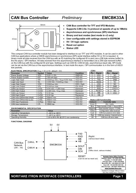
This compact <strong>CAN</strong> bus controller module has been designed to interface to our TFT and <strong>VFD</strong> modules. It can be used in other<br />
<strong>CAN</strong> bus applications where a CMOS asynchronous or synchronous (SPI) serial interface (either 5V or 3V) is required. In<br />
binary mode all data received from the <strong>CAN</strong> bus with an ID matching the configured ID is sent (via a 256 byte receive buffer) to<br />
the the async / SPI interface. All data received from the asynchronous interface is transmitted (via a 256 byte transmit buffer)<br />
on the <strong>CAN</strong> bus with the configured ID and type. Settings such as <strong>CAN</strong> ID, <strong>CAN</strong> bit rate, asynchronous baud rate, SPI mode<br />
can be set via the <strong>CAN</strong> bus or the asynchronous interface. In text mode the async / SPI communication is in the form of ASCII<br />
text packets.<br />
ELECTRICAL SPECIFICATION (Vlogic = 3V or 5V, default = 3V)<br />
Parameter Symbol Value Condition<br />
Power Supply Voltage VCC 5.0V +/- 5% GND=0V<br />
Power Supply Current ICC 100 mA (typ) VCC=5V<br />
Logic High Input VIH 0.6xVlogic min. / Vlogic+0.5V max. VCC=5V<br />
Logic Low Input VIL -0.5V min. / 0.2xVlogic max. VCC=5V<br />
Logic High Output VOH 0.8xVlogic min. IOH=-10μA<br />
Logic Low Output VOL 0.2xVlogic max. IOL=4mA<br />
<strong>CAN</strong> Low Output CVOL 0.5V min. / 1.25V max. Dominant<br />
<strong>CAN</strong> High Output CVOH 2.45V min. / Vlogic max. Dominant<br />
<strong>CAN</strong> Low Output CVOL 2.3V typ. Recessive<br />
<strong>CAN</strong> High Output CVOH 2.3V typ. Recessive<br />
<strong>CAN</strong> Input Differential (High) CVIDH 500mV min. VCC=5V<br />
<strong>CAN</strong> Input Differential (Low) CVIDL 900mV min. VCC=5V<br />
<strong>CAN</strong> Input Hysteresis CVIhys 100mV typ. VCC=5V<br />
<strong>CAN</strong> Input resistance CRI 35KΩ typ. VCC=5V<br />
ENVIRONMENTAL SPECIFICATION<br />
Parameter Value<br />
Operating Temperature –40°C to +85°C<br />
Storage Temperature –40°C to +85°C<br />
Operating Humidity 20 to 85% RH @ 25°C non condensing<br />
FUNCTIONAL DIAGRAM<br />
<strong>CAN</strong> <strong>Bus</strong><br />
Network<br />
(20K – 1M)<br />
<strong>CAN</strong>-L<br />
<strong>CAN</strong>-H<br />
54mm<br />
CON2<br />
5V 0V<br />
<strong>EMCBK33A</strong><br />
• <strong>CAN</strong> <strong>Bus</strong> controller for TFT and <strong>VFD</strong> Modules<br />
• Supports <strong>CAN</strong> 2.0a / b protocol at speeds of up to 1Mbit/s<br />
• Asynchronous and synchronous (SPI) interfaces<br />
• Binary and text modes (text mode in v2 only)<br />
• User configurable with settings stored in EEPROM<br />
• 5V / 3V logic options<br />
• Reset out option<br />
• Status LED<br />
TXD<br />
RXD<br />
MB<br />
HB<br />
DOUT<br />
DIN<br />
SCK<br />
CON1<br />
Pin Signal<br />
1 VCC<br />
2 SCK<br />
3 TXD<br />
4 MOSI<br />
5 GND<br />
6 MISO<br />
7 RXD<br />
8 RESET<br />
9 MB<br />
10 HB<br />
Async<br />
(various baud rates)<br />
RESET<br />
(Can be set as reset out)<br />
SPI<br />
(1Mhz clock, various modes)<br />
CON2<br />
Pin Signal<br />
1 NC<br />
2 <strong>CAN</strong>-L<br />
3 GND<br />
4 NC<br />
5 NC<br />
6 GND<br />
7 <strong>CAN</strong>-H<br />
8 NC<br />
9 VCC<br />
Status LED functionality<br />
Colour <strong>Controller</strong> state<br />
Green Idle / ready<br />
Blue Data transfer (<strong>CAN</strong> -> Async/SPI)<br />
Magenta Data transfer (Async -> <strong>CAN</strong>)<br />
Yellow Configuration data received<br />
Cyan <strong>CAN</strong> bus passive error state<br />
Red <strong>CAN</strong> bus receive / transmit error<br />
Off <strong>CAN</strong> bus off error state<br />
<strong>Noritake</strong> Sales Office Tel Nos<br />
Nagoya Japan: +81 (0)52-561-9867<br />
Canada: +1-416-291-2946<br />
Chicago USA: +1-847-439-9020<br />
Munchen (D): +49 (0)89-3214-290<br />
<strong>Itron</strong> UK: +44 (0)1493 601144<br />
Rest Europe: +49 (0)61-0520-9220<br />
www.noritake-itron.com<br />
Subject to change without notice.<br />
Doc Ref: 42420 Iss:2 10Jun11<br />
NORITAKE ITRON INTERFACE CONTROLLERS Page 1
<strong>CAN</strong> <strong>Bus</strong> <strong>Controller</strong> <strong>Preliminary</strong> <strong>EMCBK33A</strong><br />
Operating modes<br />
Communication with the <strong>EMCBK33A</strong> can be in binary or text format. The factory default mode is binary (this is the only mode available in the<br />
v1 product). When the operating mode is changed the mode is stored in EEPROM.<br />
In binary mode every <strong>CAN</strong> data message received with the configured receive ID is processed and the data bytes extracted from the packet<br />
and sent in raw binary format to the target device. Each byte received from the target device is sent on the <strong>CAN</strong> bus with the configured<br />
transmit ID as a single 1 byte packet. Although an ID mask can be set to allow the reception of messages from a range of <strong>CAN</strong> ID’s the <strong>CAN</strong><br />
ID itself is not communicated to the target.<br />
Text mode allows more flexibility and maintains all information about the <strong>CAN</strong> packet when transferring to / from the target device. A<br />
disadvantage of text mode is more bytes are transferred on the target side as messages are sent as ASCII text (ASCII HEX for ID and data<br />
values). Depending on the <strong>CAN</strong> bitrate and async baud rate this can lead to a limited throughput of data. Using receive ID filtering with<br />
appropriate mask values can help by limiting the range of ID’s accepted. Text mode is preferred when using the <strong>EMCBK33A</strong> with the iSMART<br />
TFT modules because processing of the incoming data on the async port AS1 can be triggered on and the preceding text packet<br />
analyzed using a series of CALC commands to determine packet type, ID, length, payload data, etc. Transmission is also more flexible as a<br />
<strong>CAN</strong> message can be sent with any ID on the fly using the same, easy to read text format.<br />
Binary mode<br />
Configuration<br />
Default settings are <strong>CAN</strong> ID = 155h, both 11 bit and 29 bit ID <strong>CAN</strong> messages received, 11 bit <strong>CAN</strong> messages transmitted, <strong>CAN</strong> bit rate of<br />
1Mbit/s, asynchronous baud rate = 38400, SPI mode 0 (fixed 1Mhz clock speed). When a configuration command is received the new<br />
configuration settings are stored in EEPROM and the controller performs an internal reset and the new settings are used immediately. Only a<br />
small selection of settings are available if configured using the internal jumper links.<br />
Changing the configuration via the <strong>CAN</strong> bus<br />
Setup via the <strong>CAN</strong> bus is achieved by sending a single <strong>CAN</strong> message with ID=0h (either 11 or 29 bit ID accepted). The data length of all <strong>CAN</strong><br />
configuration messages must be 8 bytes (unused parameter bytes at the end of the packet must be sent but can be any value). The format of<br />
the 8 data bytes is as follows :-<br />
Byte 1 Byte 2 Byte 3 Byte 4 Byte 5 Byte 6 Byte 7 Byte 8<br />
‘C’ ‘f’ type param1 param2 param3 param4 param5<br />
If a message is received via <strong>CAN</strong> with an ID of 0h that does not match this format no further messages with ID of 0h are processed until the<br />
controller is powered OFF / ON.<br />
Changing the configuration via the asynchronous interface<br />
Setup via the asynchronous interface is achieved by sending a configuration sequence at the currently selected baud rate. Unlike setting via<br />
the <strong>CAN</strong> bus the packet length depends on the configuration type.<br />
Byte 1 Byte 2 Byte 3 Byte 4 Byte 5 – Byte n<br />
1Bh ’C’ ‘f’ type param1 paramn<br />
Configuration commands – [1Bh] is sent first when sending the configuration via the asynchronous interface.<br />
‘A’ Set Async baud rate<br />
Set the asynchronous baud rate<br />
[1Bh] 43h 66h 41h baud<br />
Baud -<br />
4800 00h<br />
9600 01h<br />
19200 02h<br />
38400 03h<br />
57600 04h<br />
115200 05h<br />
‘B’ Set <strong>CAN</strong> bit rate<br />
Set the <strong>CAN</strong> bit rate from a range of common values. Different bit rates are possible by using the custom option.<br />
[1Bh] 43h 66h 42h rate<br />
[1Bh] 43h 66h 42h rate [b1] [b2] [b3]<br />
Rate -<br />
20K 00h<br />
50K 01h<br />
100K 02h<br />
125K 03h<br />
200K 04h<br />
250K 05h<br />
500K 06h<br />
1M 07h<br />
Custom FFh (uses b1, b2 and b3 to create non-standard bit rate – contact us for details)<br />
NORITAKE ITRON INTERFACE CONTROLLERS Page 2
<strong>CAN</strong> <strong>Bus</strong> <strong>Controller</strong> <strong>Preliminary</strong> <strong>EMCBK33A</strong><br />
‘C’ Set <strong>CAN</strong> receive / transmit modes and select either Async / SPI mode<br />
Set either asynchronous or SPI mode. Set whether 11 bit or 29 bit ID will be used for <strong>CAN</strong> transmit. Set the <strong>CAN</strong> receiver to accept 11 bit, 29 bit or both<br />
formats.<br />
[1Bh] 43h 66h 43h mode<br />
Mode -<br />
Bit 7 Bit 6 Bit 5 Bit 4 Bit 3 Bit 2 Bit 1 Bit 0<br />
A/S - - - - <strong>CAN</strong>TX <strong>CAN</strong>RX2 <strong>CAN</strong>RX1<br />
A/S 0=Async, 1=SPI<br />
<strong>CAN</strong>TX 0=11 bit <strong>CAN</strong> transmit mode, 1=29 bit <strong>CAN</strong> transmit mode<br />
<strong>CAN</strong>RX 01=11 bit <strong>CAN</strong> receive mode, 10=29 bit <strong>CAN</strong> receive mode, 11=both 11 and 29 bit <strong>CAN</strong> receive mode<br />
‘Y’ Enter text mode – controller is reset after this command<br />
After this command is sent the controller operates in text mode.<br />
‘Z’ Reset controller to factory defaults<br />
‘R’ Set <strong>CAN</strong> receive ID (11 bit)<br />
Specify the 11 bit ID to use for <strong>CAN</strong> receive.<br />
[1Bh] 43h 66h 52h 00h [b1] [b2]<br />
b1 11 bit ID (bits 10-8)<br />
b2 11 bit ID (bits 7-0)<br />
‘R’ Set <strong>CAN</strong> receive ID (29 bit)<br />
Specify the 29 bit ID to use for <strong>CAN</strong> receive.<br />
[1Bh] 43h 66h 52h 01h [b1] [b2] [b3] [b4]<br />
b1 29 bit ID (bits 28-24)<br />
b2 29 bit ID (bits 23-16)<br />
b3 29 bit ID (bits 15-8)<br />
b4 29 bit ID (bits 7-0)<br />
‘T’ Set <strong>CAN</strong> transmit ID (11 bit)<br />
Specify the 11 bit ID to use for <strong>CAN</strong> transmit.<br />
[1Bh] 43h 66h 54h 00h [b1] [b2]<br />
b1 11 bit ID (bits 10-8)<br />
b2 11 bit ID (bits 7-0)<br />
‘T’ Set <strong>CAN</strong> transmit ID (29 bit)<br />
Specify the 29 bit ID to use for <strong>CAN</strong> transmit.<br />
[1Bh] 43h 66h 54h 01h [b1] [b2] [b3] [b4]<br />
b1 29 bit ID (bits 28-24)<br />
b2 29 bit ID (bits 23-16)<br />
b3 29 bit ID (bits 15-8)<br />
b4 29 bit ID (bits 7-0)<br />
‘S’ Set SPI mode<br />
Sets SPI parameters. SPI is currently operational in transmit only (<strong>EMCBK33A</strong> -> Module). Data order, polarity and phase can be set. Clock frequency is<br />
fixed at 1Mhz.<br />
[1Bh] 43h 66h 53h mode<br />
Mode<br />
Bit 7 Bit 6 Bit 5 Bit 4 Bit 3 Bit 2 Bit 1 Bit 0<br />
- - - - - DORD POL PHASE<br />
DORD 0=MSB sent first, 1=LSB sent first<br />
POL 0=clock idle low, 1=clock idle high<br />
PHASE 0=leading edge clock, 1=trailing edge clock<br />
NORITAKE ITRON INTERFACE CONTROLLERS Page 3
<strong>CAN</strong> <strong>Bus</strong> <strong>Controller</strong> <strong>Preliminary</strong> <strong>EMCBK33A</strong><br />
Example setup<br />
The controller is to be used on a <strong>CAN</strong> 2.0a (11 bit ID, receive and transmit) bus network operating at 50K. The controller will be<br />
set to respond to a <strong>CAN</strong> ID of 723h. It will connect to a <strong>VFD</strong> module via the asynchronous interface with a baud rate of 19200.<br />
The following configuration commands should be sent to setup the controller :-<br />
Setup via <strong>CAN</strong> bus<br />
43h 66h 41h 02h 00h 00h 00h 00h Set async baud rate<br />
43h 66h 42h 01h 00h 00h 00h 00h Set <strong>CAN</strong> bit rate<br />
43h 66h 43h 01h 00h 00h 00h 00h Set modes<br />
43h 66h 52h 00h 07h 23h 00h 00h Set 11 bit <strong>CAN</strong> receive ID<br />
43h 66h 54h 00h 07h 23h 00h 00h Set 11 bit <strong>CAN</strong> transmit ID<br />
Changing the configuration via the internal jumper links<br />
Only a small selection of possible settings are available if configured<br />
using the internal jumper links J1 – J4.<br />
Text mode (v2 only)<br />
Overview<br />
In text mode all communication between the <strong>EMCBK33A</strong> v2 and the target device is in the form of ASCII text packets.<br />
Commands to controller<br />
O Open the <strong>CAN</strong> channel (LED bright cyan) (stored in EEPROM, default = closed)<br />
<strong>CAN</strong> messages can be sent and received. The bitrate must be set up before the <strong>CAN</strong> channel is opened.<br />
C Close the <strong>CAN</strong> channel (LED dim cyan) (stored in EEPROM, default = closed)<br />
No <strong>CAN</strong> messages can be sent or received.<br />
Br Set standard <strong>CAN</strong> bit rate (stored in EEPROM, default = 1M)<br />
r=0 20K<br />
r=1 50K<br />
r=2 100K<br />
r=3 125K<br />
r=4 200K<br />
r=5 250K<br />
r=6 500K<br />
r=7 1M<br />
This command should be sent while the <strong>CAN</strong> channel is closed.<br />
bxxyyzz Sets custom <strong>CAN</strong> bit rate (stored in EEPROM)<br />
Register 1 xx xddddddx d=divider<br />
Register 2 yy xssxpppx ss=SJW, p=propogation<br />
Register 3 zz xhhhHHHx h=phase2, H=phase1<br />
Bitrate (bps) = 16000000 / [ (divider+1) x ( 1+ (p+1) + (h+1) + (H+1) ) ]<br />
Example – 88.8Kbps<br />
<strong>EMCBK33A</strong> with case removed<br />
JR<br />
LED<br />
J1<br />
J2<br />
J3<br />
J4<br />
Divider (to derive TQ from master clock) = 8<br />
xx x001000x<br />
yy x10x111x<br />
zz x100101x b104E4A<br />
This command should be sent while the <strong>CAN</strong> channel is closed.<br />
JL<br />
Setup via the asynchronous interface<br />
1Bh 43h 66h 41h 02h Set async baud rate<br />
1Bh 43h 66h 42h 01h Set <strong>CAN</strong> bit rate<br />
1Bh 43h 66h 43h 01h Set modes<br />
1Bh 43h 66h 52h 00h 07h 23h Set 11 bit <strong>CAN</strong> receive ID<br />
1Bh 43h 66h 54h 00h 07h 23h Set 11 bit <strong>CAN</strong> transmit ID<br />
INTERNAL JUMPER LINK SETTINGS<br />
Jumper Connect Function<br />
JL<br />
Open<br />
Link<br />
3V signal level*<br />
5V signal level<br />
JR<br />
Open<br />
Link<br />
Reset out (future option)<br />
Reset in*<br />
J1<br />
Open<br />
Link<br />
Settings from EEPROM*<br />
Settings from J2,J3,J4<br />
J2<br />
Open<br />
Link<br />
19200 baud<br />
115200 baud<br />
J3<br />
Open<br />
Link<br />
2AAh <strong>CAN</strong> ID<br />
3BCh <strong>CAN</strong> ID<br />
J4<br />
Open<br />
Link<br />
100K <strong>CAN</strong> speed<br />
250K <strong>CAN</strong> speed<br />
* = default link setting<br />
NORITAKE ITRON INTERFACE CONTROLLERS Page 4
<strong>CAN</strong> <strong>Bus</strong> <strong>Controller</strong> <strong>Preliminary</strong> <strong>EMCBK33A</strong><br />
txxxl[data] Send a standard 11 bit data <strong>CAN</strong> message with ID of xxx, length l and optional data<br />
Only valid if <strong>CAN</strong> channel is open.<br />
Example t100410203040 sends an 11 bit packet with ID of 100h and 4 data bytes 10h, 20h, 30h, 40h<br />
Txxxxxxxxl[data] Send an extended 29 bit data <strong>CAN</strong> message with ID of xxxxxxxx, length l and optional data<br />
Only valid if <strong>CAN</strong> channel is open.<br />
Example T000012FE1F5 sends a 29 bit packet with ID of 000012FEh and 1 data bytes F5h<br />
rxxxl Send a standard 11 bit remote <strong>CAN</strong> message with ID of xxx and length l<br />
Only valid if <strong>CAN</strong> channel is open.<br />
Example r7FE3 sends an 11 bit RTR packet with ID of 7FEh with length of 3<br />
Rxxxxxxxxl Send an extended 29 bit remote <strong>CAN</strong> message with ID of xxxxxxxx and length l<br />
Only valid if <strong>CAN</strong> channel is open.<br />
Example r100000FE2 sends a 29 bit RTR packet with ID of 100000FEh with length of 2<br />
ixxx Set standard 11 bit receive ID (stored in EEPROM, default = 000)<br />
Example i7FF sets 11 bit receive ID to 7FFh (see corresponding mask command for message filtering)<br />
mxxx Set standard 11 bit receive MASK (stored in EEPROM, default = 000). Use in conjunction with receive ID to set up<br />
receive filtering.<br />
Ixxxxxxxx Set extended 29 bit receive ID (stored in EEPROM, default = 00000000)<br />
Mxxxxxxxx Set extended 29 bit receive MASK (stored in EEPROM, default = 00000000)<br />
Xn Enable / disable timestamp info on RX packets (0=disable, 1=enable) (stored in EEPROM, default = disabled)<br />
Un Sets async baud rate (stored in EEPROM, default = 38400)<br />
0=4800<br />
1=9600<br />
2=19200<br />
3=38400<br />
4=57600<br />
5=115200<br />
Q Return version information and current configuration<br />
F Return <strong>CAN</strong> status flags in the form Fxx<br />
bit 7 -<br />
bit 6 timestamp enabled<br />
bit 5 <strong>CAN</strong> enabled<br />
bit 4 <strong>CAN</strong> initiated<br />
bit 3 -<br />
bit 2 -<br />
bit 1 bus off error<br />
bit 0 passive error<br />
Y Enter binary mode – controller is reset after this command<br />
Z Reset controller to factory defaults<br />
Lrrggbb LED test - sets colour to RGB HEX values<br />
Format of commands received<br />
dxxxl[data][tttt] Standard data <strong>CAN</strong> message received with ID, length, optional data and timestamp data if enabled<br />
Dxxxxxxxxl[data][tttt] Extended data <strong>CAN</strong> message received with ID, length, optional data and timestamp data if enabled<br />
rxxxl[tttt] Standard remote <strong>CAN</strong> message received with ID, length and timestamp data if enabled<br />
Rxxxxxxxxl[tttt] Extended remote <strong>CAN</strong> message received with ID, length and timestamp data if enabled<br />
Example setup<br />
For use in an 250Kbps 11 bit system. Filter so only packets with ID’s between 170h and 17Fh are received. Enable receive timestamp.<br />
B5 Set bitrate<br />
i170 Set ID<br />
m7F0 Set mask<br />
X1 Enable timestamp<br />
O Open <strong>CAN</strong> channel<br />
NORITAKE ITRON INTERFACE CONTROLLERS Page 5


