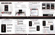
Superchips Redline Users Manual - RealTruck.com
Superchips Redline Users Manual - RealTruck.com
Superchips Redline Users Manual - RealTruck.com

You also want an ePaper? Increase the reach of your titles
YUMPU automatically turns print PDFs into web optimized ePapers that Google loves.
user manual<br />
read all safety warnings and cautions prior to using this product
T A B L E O F C O N T E N T S<br />
TABLE OF CONTENTS<br />
SAFETY ....................................................................4<br />
SAFETY WARNING & CAUTION ..................................................... 4<br />
SAFETY GUIDELINES .................................................................... 5<br />
LIMITED 1 YEAR WARRANTY ........................................................ 6<br />
WARRANTY ..............................................................6<br />
VEHICLE WARRANTIES ................................................................. 6<br />
READ ME ..................................................................8<br />
PRODUCT REGISTRATION ............................................................ 8<br />
PARTS INCLUDED ......................................................................... 9<br />
IN THE BOX ..............................................................9<br />
OPERATING INSTRUCTIONS ................................10<br />
SCREEN LAYOUTS & FUNCTIONALITY ...................................... 10<br />
GETTING STARTED ....................................................................... 11<br />
VEHICLE PARAMETER ID’s (PIDs) ................................................11<br />
NAVIGATING THE MAIN MENU ................................................... 12<br />
SHOW ALERTS ......................................................................... 12<br />
2<br />
SHOW MAINTENANCE DUE......................................................... 13<br />
DIAGNOSTICS .......................................................................... 13<br />
--TROUBLE CODES-- ............................................................... 13<br />
--PERFORMANCE TESTS-- ....................................................... 13<br />
--RECORDS--......................................................................... 14<br />
--MILEAGE COACH-- ............................................................... 14<br />
--DATA LOGGING-- ................................................................. 17<br />
MAINTENANCE MANAGER .......................................................... 17<br />
--ODOMETER SETUP-- ............................................................. 18<br />
--MAINTENANCE SETUP-- ........................................................ 18<br />
--ALERT THRESHOLD-- ........................................................... 19<br />
OPTIONS MENU ....................................................................... 19<br />
--ALERT OPTIONS (SETTINGS)-- ............................................... 19<br />
--SOUND DURATION-- ............................................................ 20<br />
--SCREEN LAYOUT-- .............................................................. 20<br />
--BACKLIGHT AUTODIM-- ......................................................... 21<br />
--MENU TIME-OUT-- ................................................................ 21<br />
--ACCESSORY OPTIONS-- ....................................................... 21<br />
--UNITS-- ............................................................................. 22<br />
--FACTORY RESET-- ............................................................... 22<br />
HELP MENU ............................................................................ 22<br />
--PRODUCT INFO-- ................................................................ 22<br />
--VEHICLE INFO-- .................................................................. 23<br />
--CONTACT INFO-- ................................................................. 23<br />
--TECHNICAL SUPPORT TOOLS-- ............................................. 23
T A B L E O F C O N T E N T S<br />
PROGRAMMING THE VEHICLE ...................................................24<br />
--PROGRAMMING LEVELS-- .....................................................24<br />
CUSTOMIZATION .........................................................................26<br />
FUSION SOFTWARE UPDATES ...................................................27<br />
INTERNET UPDATES ............................................ 27<br />
USING FUSION SOFTWARE ........................................................27<br />
PROGRAMMING ERRORS ...........................................................28<br />
--UPDATE REQUIRED-- ............................................................28<br />
--NON-STOCK CONDITION-- .....................................................29<br />
APPENDIX ............................................................. 29<br />
TIPS .............................................................................................30<br />
TROUBLE-SHOOTING ................................................................. 31<br />
COMMONLY USED ACRONYMS ..................................................32<br />
INDEX ................................................................... 33<br />
3
S A F E T Y<br />
S A F E T Y W A R N I N G & C A U T I O N<br />
Throughout this User Guide (hereafter noted as User <strong>Manual</strong> or<br />
<strong>Manual</strong>) you will see important messages regarding your safety or<br />
the protection of your vehicle. These messages are designated by<br />
the words WARNING or CAUTION.<br />
WARNING indicates a condition that may cause serious<br />
injury or death to you, your passengers or others nearby. Pay<br />
careful attention to these Warning messages, and always <strong>com</strong>ply<br />
with them. They could save a life.<br />
CAUTION indicates a condition that could cause damage to<br />
your vehicle. It is important to install and operate your <strong>Superchips</strong><br />
product in conformance with instructions in this <strong>Manual</strong>.<br />
Cautions alert you to particularly important things that will keep<br />
your vehicle operating properly.<br />
This <strong>Superchips</strong> Product is a high-performance product. As such,<br />
it does present some risks of which you should be fully aware. Do<br />
not use this product until you have carefully read the following safety<br />
information and the Owner Agreement.<br />
NOTE: After the device has been installed, the screen and logo<br />
will appear followed by a warning and <strong>com</strong>pliance directive. To<br />
indicate you accept and acknowledge the warning and <strong>com</strong>pliance,<br />
press the [ENTER] or [YES] button.<br />
4
S A F E T Y<br />
S A F E T Y G U I D E L I N E S<br />
1. Do not exceed legal speed limits on public roadways. Use any<br />
enhanced speed capabilities of this product only in closed circuit,<br />
legally sanctioned racing environments expressly for this purpose.<br />
Loss of control from speeding on a public road could seriously injure<br />
you, your passengers, or others on the roadway.<br />
2. Do not operate the device while driving. Perform all adjustments<br />
or changes while stopped. Changing a setting while driving can interfere<br />
with your attention to roadway conditions.<br />
3. “ Stacking” performance-enhancing devices or other improper installation<br />
can cause power train failure on the road. Other products<br />
may have features in<strong>com</strong>patible with your device. Follow all installation<br />
and operating instructions, and do not stack products.<br />
4. Some modifications may affect other parts of your vehicle. For example,<br />
if you remove/adjust the speed limiter in your vehicle, be sure<br />
your tires and other <strong>com</strong>ponents are rated for the increased speeds<br />
they will have to withstand. Not doing so can lead to loss of vehicle<br />
control. Modify the speed limiter only for use in closed circuit, legally<br />
sanctioned racing environments, not for use on public roadways.<br />
WARNING<br />
Misapplication or misuse of this product could lead to a serious<br />
or fatal accident. Comply with all safety information in<br />
this manual, and your vehicle owner’s manual. Follow safety,<br />
installation and operating instructions in this User <strong>Manual</strong> to<br />
assure proper use.<br />
5
W A R R A N T Y<br />
L I M I T E D 1 Y E A R W A R R A N T Y<br />
LIMITED 1 YEAR WARRANTY<br />
• <strong>Superchips</strong>, (hereafter “SELLER”) gives Limited Warranty as to description, quality,<br />
merchantability, fi tness for any product’s purpose, productiveness, or any other matter<br />
of SELLER’s product sold herewith. The SELLER shall be in no way responsible for the<br />
product’s open use and service and the BUYER hereby waives all rights other than those<br />
expressly written herein. This Warranty shall not be extended or varied except by a written<br />
instrument signed by SELLER and BUYER.<br />
• The Warranty is Limited to one (1) year from the date of sale and limited solely to the<br />
parts contained within the product’s kit. All products that are in question of Warranty must<br />
be returned shipping prepaid to the SELLER and must be ac<strong>com</strong>panied by a dated proof<br />
of purchase receipt. All Warranty claims are subject to approval by <strong>Superchips</strong>.<br />
• Under no circumstances shall the SELLER be liable for any labor charged or travel time<br />
incurred in diagnosis for defects, removal, or reinstallation of this product, or any other<br />
contingent expenses.<br />
• If the BUYER sends back a failed unit that is out of warranty and chooses to buy a<br />
refurbished unit, the refurbished unit will only carry a 90 day warranty. If the BUYER<br />
purchases a new unit at a predetermined discounted rate, it will have the standard 1 year<br />
warranty.<br />
• Under no circumstances will the SELLER be liable for any damage or expenses insured<br />
by reason of the use or sale of any such equipment.<br />
• THE INSTALLATION OF THIS PRODUCT INDICATES THAT THE BUYER HAS READ<br />
AND UNDERSTANDS THIS AGREEMENT AND ACCEPTS ITS TERMS AND CONDI-<br />
TIONS.<br />
• IN THE EVENT THAT THE BUYER DOES NOT AGREE WITH THIS AGREEMENT,<br />
THE BUYER MAY PROMPTLY RETURN THIS PRODUCT, IN A NEW AND UNUSED<br />
CONDITION, WITH A DATED PROOF OF PURCHASE, TO THE PLACE OF PURCHASE<br />
WITHIN THIRTY (30) DAYS FROM DATE OF PURCHASE FOR A FULL REFUND.<br />
• NOTE: This warranty is void for any new products purchased through auction<br />
web sites. Warranty is valid only for new products purchased through Authorized<br />
Dealers (proof of purchase required for all warranty claims).<br />
V E H I C L E W A R R A N T I E S<br />
IMPORTANT INFORMATION<br />
• Many of our customers ask, “Will your product void my vehicle’s manufacturer’s warranty?”<br />
While the answer is straightforward from a legal standpoint, it’s important to educate<br />
our customers (and all aftermarket consumers) on some industry realities and offer some<br />
<strong>com</strong>mon sense precautions to minimize your risk. <strong>Superchips</strong> is <strong>com</strong>mitted to providing<br />
quality products that are safe to use. Our products do not cause damage to a vehicle<br />
when used as intended.<br />
• Consumers of aftermarket products are protected by the Federal Magnusson-Moss<br />
Warranty Act. The Act states that if something breaks on your vehicle and you take it in for<br />
warranty repair, the dealer must honor your warranty unless whatever modifications you<br />
have added to your vehicle actually caused the problem in question.<br />
• However, the reality is that many dealerships have been known to void warranties on<br />
vehicles that use aftermarket products as a matter of policy. This applies in particular to<br />
those aftermarket products that produce horsepower, such as performance enhancement<br />
“chips,” modifi ed intake manifolds, or aftermarket exhaust systems, regardless of product<br />
brand.<br />
• You have strong legal protection as a consumer in regard to your vehicle’s warranty.<br />
6
W A R R A N T Y<br />
However, <strong>Superchips</strong> strongly re<strong>com</strong>mends you always disconnect and remove your<br />
module/programmer and monitor when you take your vehicle to a dealer for warranty<br />
work. In addition, leaving the product connected may affect dealer diagnostic analysis and<br />
scan tool functions. <strong>Superchips</strong> makes every effort to produce product that can be easily<br />
removed.<br />
• NOTE: Even if you disconnect your device, your dealer can detect the use of any<br />
programmer—even if the device has been removed.<br />
SERVICE CENTER AND COMPATIBILITY CAUTIONS<br />
• CAUTION: RETURN YOUR VEHICLE TO STOCK BEFORE TAKING IT TO A SER-<br />
VICE CENTER. All <strong>Superchips</strong> modules and programmers are built to operate with OEM<br />
calibrations. If you take your vehicle to a service center they may, by your request or<br />
otherwise, update your vehicle’s calibrations. If this happens and your vehicle has not<br />
been returned to stock your device will no longer be capable of programming your vehicle.<br />
<strong>Superchips</strong> updates its active products (i.e. those currently being manufactured) to work<br />
effectively with updated OEM calibrations. However, this process can take some time as<br />
<strong>Superchips</strong> is not always made aware of calibration changes made by the OEM. In the<br />
case of discontinued products, <strong>Superchips</strong> cannot ensure that your unit will work effectively<br />
if you take your vehicle to a dealership and you are given, by your request or otherwise,<br />
a new calibration.<br />
• CAUTION: If you have used another tuner/programmer on your vehicle, you will<br />
need to program the vehicle back to stock and remove the device before using this<br />
product. Failure to return to stock may result in PCM failure or engine damage. Programming<br />
your vehicle may expose existing defects in the vehicle’s PCM that could<br />
disable your vehicle. It is advised that you do not program your vehicle in remote<br />
locations in case of vehicle failure.<br />
• CAUTION: The SCR programmer was developed on stock vehicles with no aftermarket<br />
bolt-on parts; as such, the performance changes implemented by the SCR<br />
may not be <strong>com</strong>patible with certain aftermarket power add-ons. See below for a<br />
brief explanation of how the SCR tuning may be affected by certain aftermarket<br />
devices.<br />
COLD AIR INTAKE (CAI) KITS<br />
There are currently a large number of CAI kits on the market. These kits are designed to<br />
improve air fl ow and temperature. Some of these kits may be <strong>com</strong>patible with the SCR<br />
programmer; however others may cause a lean condition when used in conjunction with<br />
the SCR tuning.<br />
MECHANICAL MODIFICATIONS<br />
Mechanical modifi cations such as headers, upgraded camshafts, displacement changes,<br />
cylinder head improvements etc. will change the airflow characteristics of an internal <strong>com</strong>bustion<br />
engine. This may cause the tuning to be in<strong>com</strong>patible with the SCR tuning.<br />
FORCED INDUCTION (TURBOCHARGERS OR SUPERCHARGERS)<br />
Turbochargers and Superchargers drastically change the dynamics/performance of the<br />
engine, and its fueling/timing needs. Additional hard parts and custom tuning are required<br />
to run a forced induction system on an engine that was originally designed as a Naturally<br />
Aspirated (NA) engine.<br />
7
R E A D M E<br />
P R O D U C T R E G I S T R A T I O N<br />
BENEFITS OF PRODUCT REGISTRATION<br />
-Your Safety - Registering your product allows us to know exactly which<br />
product you have and provide important product updates to you that improve<br />
the quality and/or safety of the product.<br />
-Enhanced Features - All <strong>Superchips</strong> products are easily updated via the<br />
internet. We are constantly adding new features and improvements to<br />
our product that we know you will want to enjoy.<br />
-Confirmation of Ownership - Provides a record in case of product loss,<br />
theft, or required warranty work. When you call us for support our team<br />
will already have much of the information they need to help you.<br />
-Improved Product Development - Helps us better understand you (our<br />
customers) and design products that meet your needs.<br />
-Special Offers - Allows us to inform you about special offers on accessories<br />
and/or new products that fit your vehicle and enhance your driving<br />
experience.<br />
C A R B / E P A C O M P L I A N C E<br />
NOTE: The stickers included in some products apply to products that have<br />
received CARB certification for emissions <strong>com</strong>pliance.<br />
This product meets the emissions <strong>com</strong>pliance requirements<br />
of the California Air Resources Board and Federal<br />
Environmental Protection Agency and is legal for sale and<br />
use on pollution-controlled vehicles operated on public<br />
streets and highways. It must be installed and operated<br />
according to the instructions provided in this user’s<br />
manual. Included with this product is a sticker like the one<br />
FOR 2005-2013 GAS ENGINES<br />
CARB E.O. NO. X-XXX-XX<br />
1790 E. Airport Blvd. Sanford, Florida 32773<br />
1-888-227-2447<br />
pictured for you to keep in your vehicle. You can either apply it somewhere on<br />
the vehicle (e.g., the inside end of driver’s door) or simply store it in your glove<br />
box. The purpose of these stickers is to inform anyone who may have questions<br />
regarding the use of your <strong>Superchips</strong> product and how it affects emissions. For<br />
example, it would be something to show an emissions technician if questioned<br />
when taking your vehicle in for an emissions check to let him/her know the product<br />
is CARB emissions <strong>com</strong>pliant.<br />
8
P A R T S I N C L U D E D<br />
SCR DEVICE<br />
The SCR device provides you with an interface to<br />
change the performance programming of your vehicle<br />
and display multiple vehicle parameters in real time.<br />
WINDSHIELD MOUNT<br />
The mount supplied with your kit is designed to give<br />
you flexibility in mounting your device anywhere on<br />
your windshield. It is equipped with a locking suction<br />
cup, a vertically adjustable arm, and a 180 pivot head<br />
which allows you to fine tune the viewing angle.<br />
OBDII CABLE<br />
The purpose of this cable is to provide a <strong>com</strong>munication<br />
link between your vehicle and your device<br />
as well as power.<br />
MINI USB CABLE<br />
The USB cable is used to connect your device to<br />
your PC in order to perform firmware and calibration<br />
updates using the Fusion software.<br />
I N T H E B O X<br />
COMPACT DISC (CD)<br />
The <strong>com</strong>pact disc contains the Fusion software for easy internet<br />
updates, and the MyStyle Software for customizing your<br />
display screen, datalogging, and managing your EAS<br />
devices.<br />
ALCOHOL PAD<br />
The alcohol pad is supplied for cleaning the windshield<br />
prior to mounting the suction cup mount.<br />
ZIP-TIES<br />
Use these zip-ties to fasten the OBDII cable<br />
under the dash, and away from moving parts<br />
such as foot pedals.<br />
9
O P E R A T I N G I N S T R U C T I O N S<br />
S C R E E N L A Y O U T S & F U N C T I O N A L I T Y<br />
DIGITAL GAUGES<br />
8 Gauge Layout<br />
6 Gauge<br />
4 Gauge<br />
2 Gauge<br />
5<br />
1<br />
ANALOG GAUGES<br />
2 4 6 7<br />
3<br />
3<br />
5<br />
4<br />
1. The Up/Down Arrow Buttons are used to select the menu items and increase<br />
or decrease values.<br />
2. The Menu Button gives you access to the main menu or can be used to exit<br />
out of a menu screen.<br />
3. The Enter Button, if pressed, directs you to the PID Menu where you are<br />
able to modify what each gauge displays.<br />
4. Analog Gauges display vehicle Parameter IDs (PIDs)<br />
5. Digital Gauges display vehicle Parameter IDs (PIDs)<br />
6. The Alert Indicator light will illuminate (red) when an alert limit is exceeded.<br />
If the light is blue and contains a wrench your Maintenance Manager is<br />
letting you know a maintenance item is ready to be serviced.<br />
7. The Power Level Indicator represents the current power level. 0 represents<br />
stock.<br />
10
VEHICLE PARAMETER ID’s ( PIDs)<br />
O P E R A T I N G I N S T R U C T I O N S<br />
G E T T I N G S T A R T E D<br />
To change what PID each gauge displays, follow these steps:<br />
STEP 1 - PRESS ENTER<br />
STEP 2 - CHOOSE THE<br />
GAUGE TO MODIFY, THEN<br />
PRESS ENTER<br />
STEP 3 - SELECT A NEW PID FROM THE PROVIDED LIST<br />
STEP 4 - SET THE ALERT VALUES ACCORDINGLY.<br />
(FOR MORE INFORMATION ON ALERT SETTINGS,<br />
PLEASE REFER TO THE ALERT OPTIONS (SETTINGS)<br />
SECTION<br />
STEP 5 - CHOOSE A GAUGE COLOR. (COLORS CAN<br />
ONLY BE MODIFIED ON ANALOG STYLE GAUGES)<br />
STEP 6 - VIEW PID INFORMATION TO UNDERSTAND<br />
WHAT THE PID IS AND/OR WHAT IT MONITORS<br />
STEP 7 - WHEN YOU ARE FINISHED, EXIT THE MENU<br />
11
O P E R A T I N G I N S T R U C T I O N S<br />
N A V I G A T I N G T H E M A I N M E N U<br />
sound (only if the sound is<br />
turned on for that specifi c PID).<br />
The sound will turn off after a<br />
few seconds depending on the<br />
sound duration you have set.<br />
NOTE: The following will only show<br />
under certain circumstances:<br />
1. “Show Alerts” will only show if an<br />
alert is active.<br />
2. “Show Maintenance Due” will<br />
only show if your Maintenance Manager<br />
is turned on and a maintenance<br />
item is due.<br />
SHOW ALERTS<br />
If this option is displayed in the<br />
MAIN MENU, the SCR device<br />
is alerting you that one or more<br />
of the PARAMETER IDs (PIDs)<br />
being displayed is outside the<br />
values you specified. There are<br />
two methods in which the alerts<br />
are viewed:<br />
MAIN SCREEN METHOD<br />
While viewing the gauges, two<br />
things will automatically occur:<br />
1. The alert notification will<br />
2. The gauge value will fl ash<br />
red. It will continue fl ashing as<br />
long as the parameter is outside<br />
the user-defi ned value.<br />
ALERTS SCREEN METHOD<br />
The Alerts<br />
screen will show<br />
all parameters<br />
for which an<br />
alert has been<br />
set. If an alert value is outside<br />
the user-defi ned setting, it will<br />
flash red. The Alerts screen will<br />
stay in view for a minimum of<br />
three seconds, until no alert condition<br />
exists, or until the MENU<br />
button is pressed, at which point<br />
it will return to the main gauge<br />
screen.<br />
If you have exited the Alerts<br />
Screen you can return to the<br />
screen by entering the Main<br />
Menu and selecting Show<br />
Alerts.<br />
NOTE: For more information<br />
on how to set the Alerts, Refer<br />
to the: ALERT SETTINGS section<br />
of this manual.<br />
12
O P E R A T I N G I N S T R U C T I O N S<br />
SHOW MAINTENANCE DUE<br />
This feature allows you to quickly<br />
view which Maintenance Item<br />
is up for service. Refer to the<br />
Maintenance Manager section<br />
of this manual for more information.<br />
DIAGNOSTICS<br />
--TROUBLE CODES--<br />
When your<br />
PCM detects<br />
a problem with<br />
your vehicle it<br />
sets a trouble<br />
code. Use this menu item to<br />
retrieve the code, and to clear it<br />
after retrieval.<br />
1. Make sure the Key is in the<br />
ON position.<br />
2. Select the Trouble Codes<br />
from the Diagnostics menu.<br />
3. Select Read DTCs from the<br />
menu.<br />
---CLEAR DTCs---<br />
After you have<br />
retrieved the<br />
trouble codes<br />
and written<br />
them down,<br />
you can clear the trouble codes<br />
by selecting Clear DTCs from<br />
the menu. This will erase any<br />
of the codes currently set. If<br />
the codes <strong>com</strong>e back we re<strong>com</strong>mend<br />
you see a qualifi ed<br />
mechanic who can accurately<br />
diagnose/repair the problem.<br />
--PERFORMANCE TESTS--<br />
Performance<br />
tests can be<br />
helpful for<br />
measuring<br />
performance<br />
gains after vehicle modifi cations<br />
( e.g. intake, exhaust, programers,<br />
etc).<br />
--- READ DTCs---<br />
If you want to<br />
read the DTCs<br />
on your vehicle<br />
follow these<br />
instructions:<br />
WARNING: Do not use the<br />
Performance Tests feature to<br />
break any traffic laws.<br />
The CSR device allows you to<br />
test the performance of your<br />
vehicle by timing 0-60 and<br />
13
O P E R A T I N G I N S T R U C T I O N S<br />
quarter mile runs (instructions<br />
are provided in the Instructions<br />
menu). The results recorded by<br />
the Performance Test features<br />
will likely differ from what you’ll<br />
see on a drag-strip or other<br />
racing venues. Incorrect speedometer<br />
calibration, data sample<br />
rate, and tire slippage can cause<br />
miscalculations in the displayed<br />
results.<br />
---0 to 60 MPH TEST---<br />
After selecting<br />
the 0-60 menu<br />
option, the following<br />
screen<br />
will appear:<br />
After bringing the vehicle to a<br />
stop, follow the directions noted<br />
on the screen.<br />
---QUARTER MILE TEST---<br />
Select the<br />
Quarter Mile<br />
menu item<br />
and Figure 10<br />
will appear.<br />
After bringing the vehicle to a<br />
stop, follow the directions noted<br />
on the screen. The Quarter mile<br />
test will prompt you with a drag<br />
strip style light tree. If you watch<br />
the circles on the left they will<br />
light up yellow, then green. If<br />
you go before green appears<br />
then a red light will light up in the<br />
bottom showing that you started<br />
too early. If you don’t start early<br />
then you will see a green light<br />
remain in the bottom circle.<br />
When you’ve fi nished the quarter<br />
mile run the device will<br />
display the ending mph, the<br />
distance traveled in ft., and the<br />
elapsed time it took to reach 1/4<br />
mile. In addition it will graph<br />
your Distance vs Speed so you<br />
can better analyze the run.<br />
-- RECORDS--<br />
Records contain<br />
certain<br />
parameters for<br />
later review.<br />
This is useful<br />
on the drag strip, or when<br />
you are trying to trouble shoot a<br />
problem.<br />
-- MILEAGE COACH--<br />
The Mileage<br />
Coach feature<br />
provides<br />
useful tips and<br />
tools that help<br />
you learn ways to improve your<br />
fuel mileage.<br />
14
O P E R A T I N G I N S T R U C T I O N S<br />
There are 3 PID options that<br />
directly relate to the Mileage<br />
Coach feature. They are:<br />
Mileage Average<br />
This PID displays the calculated<br />
average MPG or L/100km and<br />
is updated continuously while<br />
driving.<br />
NOTE: The average is calculated<br />
only when the PID is<br />
being displayed on the Main<br />
Gauge Screen.<br />
This value will typically change<br />
more during start/stop driving,<br />
and less on the highway.<br />
Mileage Instantaneous This<br />
PID shows a conscientious driver<br />
how to vary the pressure on<br />
the gas pedal to save fuel every<br />
second. The value is displayed<br />
in either MPG or L/100km.<br />
Mileage Coach<br />
This PID takes the Average and<br />
Instantaneous values mentioned<br />
above and creates a visual tool<br />
to help maximize your fuel economy.<br />
This<br />
PID is best<br />
viewed using<br />
one of<br />
the Analog<br />
Gauge<br />
locations.<br />
The level<br />
indicator has been separated<br />
into 3 colors. The Green color<br />
in the middle indicates that your<br />
driving habits are producing<br />
good fuel economy. The Red<br />
indicates that your driving habits<br />
are not producing the best fuel<br />
economy and that there is room<br />
to improve. The upper “Gauge<br />
Color” (depends on the color<br />
you chose in the PID properties)<br />
indicates that your driving habits<br />
have been maximized, and you<br />
are getting the most out of your<br />
fuel.<br />
NOTE: For instruction on how<br />
to display the Mileage Coach<br />
IDs, refer to the Getting Started<br />
section of this manual.<br />
MILEAGE COACH SETUP<br />
1. Enter the MAIN MENU, select<br />
DIAGNOSTICS, then select<br />
MILEAGE COACH. The following<br />
screen will be displayed:<br />
2. Be<strong>com</strong>e familiar with each<br />
option within the Mileage Coach<br />
feature set and adjust values<br />
accordingly. Refer to the follow<br />
explanations for each of the options<br />
available.<br />
15
O P E R A T I N G I N S T R U C T I O N S<br />
---CLEAR FUEL AVERAGE---<br />
Use this option<br />
to clear<br />
the calculated<br />
average displayed<br />
in the<br />
Mileage Average PID.<br />
---LAST FUEL ECONOMY---<br />
This option<br />
allows you<br />
to enter your<br />
actual Fuel<br />
Economy<br />
Value. This value is important<br />
and should be calculated and<br />
entered regularly. This can be<br />
manually calculated by dividing<br />
the distance travelled by how<br />
much fuel you have used (Distance/Fuel<br />
= Fuel Economy).<br />
Some vehicles have their own<br />
Fuel Economy average that is<br />
displayed in cab and may be<br />
used instead of a manual calculation.<br />
---TRIP ODOMETER---<br />
This value is<br />
used to calculate<br />
the Trip<br />
Cost and Fuel<br />
Average.<br />
---FUEL PRICE---<br />
In order to<br />
calculate your<br />
Mileage and<br />
Trip Costs, the<br />
price of fuel<br />
purchased must first be entered.<br />
For example: Fuel purchased at<br />
$3.58/Gal should be entered as<br />
3.58.<br />
---MILEAGE COST---<br />
This value is<br />
a calculated<br />
average based<br />
on how many<br />
miles you have<br />
traveled and the Fuel Price you<br />
entered.<br />
---TRIP COST---<br />
This value<br />
is calculated<br />
from the Fuel<br />
Price and the<br />
Trip Odometer.<br />
---MILEAGE COACH DISPLAY---<br />
There are two<br />
ways to display<br />
the Mileage<br />
Coach<br />
PID.<br />
1. Show Difference: Difference<br />
between Instantaneous and<br />
Average.<br />
2. Show Values: Displays as<br />
Instantaneous | Average.<br />
---MILEAGE DRIVING TIPS---<br />
These tips<br />
are intended<br />
to give you<br />
general information<br />
regarding<br />
driving habits or anything<br />
that will help maximize your fuel<br />
16
O P E R A T I N G I N S T R U C T I O N S<br />
economy and overall driving<br />
experience.<br />
--DATA LOGGING--<br />
This feature<br />
allows you to<br />
record all of<br />
the available<br />
PID data on<br />
your device, so you can view it<br />
at a later time.<br />
(NOTE: The device also runs<br />
background tasks which are<br />
also recorded. This information<br />
can be ignored.)<br />
To start the recording:<br />
1. Open the Data Logging menu<br />
located under the Diagnostics<br />
menu.<br />
The following screen will appear:<br />
2. Choose one<br />
of the 5 Data<br />
Run options.<br />
The data run<br />
will turn “On”.<br />
NOTE: Only one data run can<br />
be turned on at a time.<br />
3. Return to the Main Gauge<br />
screen. The device is now in<br />
recording mode.<br />
4. Once you have recorded for<br />
a desired period of time, return<br />
to the Data Logging menu, and<br />
choose the same data run as<br />
before. (This will turn the data<br />
run “Off” and stop the device<br />
from recording. The recorded<br />
information will be stored for the<br />
My Style software to retrieve<br />
later on).<br />
NOTE: If you turn the same<br />
Data Run back “On” the previous<br />
data will be erased, and<br />
a new recording session will<br />
begin. If the indicator light<br />
is red, there is currently a<br />
recorded file associated with<br />
that run.<br />
MAINTENANCE MANAGER<br />
The Maintenance Manager<br />
calculates the odometer value<br />
of your vehicle using the vehicle<br />
speed and time.<br />
NOTE: The Maintenance Manager<br />
odometer reading may<br />
be<strong>com</strong>e out of sync with the<br />
actual dash odometer reading.<br />
You may need to periodically<br />
update the Maintenance Manager’s<br />
odometer value. It is<br />
important to note that the SCR<br />
only tracks miles traveled<br />
when the main gauge screen<br />
17
O P E R A T I N G I N S T R U C T I O N S<br />
is being displayed. If you are<br />
in the menus while driving,<br />
your miles are not calculated.<br />
--ODOMETER SETUP--<br />
1. Locate the “Maintenance<br />
Manager” by entering the “Main<br />
Menu”.<br />
2. Turn “ON” the Maintenance<br />
Manager. (If<br />
it is turned off,<br />
you will not be<br />
notified when<br />
service is<br />
due.)<br />
3. Choose<br />
“Odometer” to<br />
set your current<br />
Odometer<br />
reading.<br />
The following screen will appear:<br />
4. Use the<br />
Arrow buttons<br />
to adjust the<br />
values up or<br />
down.<br />
5. Press the Enter button to<br />
move to the next Digit.<br />
6. Once all digits have been entered,<br />
the Maintenance Manager<br />
screen will reappear showing<br />
your entered value.<br />
7. Once the Odometer is entered<br />
and displayed,<br />
chose<br />
the “Maintenance<br />
Items”<br />
option, and<br />
refer to the following section.<br />
--MAINTENANCE SETUP--<br />
1. Chose the item you would<br />
like to maintain. For demonstration<br />
purposes, the “Change<br />
Engine Oil”<br />
item will be<br />
used in this<br />
example.<br />
2. Turn the ALERT ON.<br />
NOTE: Once<br />
a Maintenance<br />
Item<br />
is turned<br />
on, the Alert<br />
Status Box<br />
to the left of<br />
the item will<br />
light up. If<br />
it is green,<br />
the item is<br />
not yet due for service. If it is<br />
yellow, the item is about to be<br />
due and within the specified<br />
Alert Threshold. If it is red,<br />
the item is due for service. If<br />
it remains black, the item is<br />
not turned on. This all depends<br />
on the following settings.<br />
18
O P E R A T I N G I N S T R U C T I O N S<br />
3. Setup the interval value. The<br />
3000 in the example will remind<br />
you every 3000<br />
miles to change<br />
the engine oil.<br />
OPTIONS MENU<br />
NOTE: Refer to your vehicle<br />
user manual to determine<br />
what value is re<strong>com</strong>mended<br />
for each Maintenance Item.<br />
4. Select the “Service Performed”<br />
option. This will automatically<br />
set the “Next Service”<br />
value.<br />
NOTE: Each<br />
time your vehicle is serviced,<br />
the “Service Performed” option<br />
will need to be selected to<br />
set the “Next Service” Value.<br />
3. The “Exit Menu” option will<br />
bring you back to the main<br />
gauge screen.<br />
--ALERT THRESHOLD--<br />
The Alert<br />
Threshold<br />
value allows<br />
you to set how<br />
many miles<br />
ahead of time you want your<br />
Maintenance Manger to alert<br />
you that an item is due.<br />
The Options menu contains<br />
items that will allow you to customize<br />
the device settings, as<br />
well as change the alert settings<br />
to best fi t your needs.<br />
--ALERT OPTIONS (SETTINGS)--<br />
The Alert Options screen allows<br />
you to turn the alerts on or<br />
off both collectively<br />
and<br />
individually. It<br />
also lets you<br />
set the alert<br />
values for each of the available<br />
PIDs.<br />
To turn alerts on:<br />
1. Select Alert Options from the<br />
Options menu.<br />
2. Select Alerts are Off/On and<br />
press enter. This will affect the<br />
entire alert<br />
system as a<br />
whole.<br />
19
O P E R A T I N G I N S T R U C T I O N S<br />
NOTE: To individually disable<br />
or enable an alert, or to<br />
change the alert follow these<br />
instructions:<br />
1. Select a PID in the Alert Options<br />
menu. NOTE: Engine<br />
RPM is being<br />
used for this<br />
example.<br />
---ALERT SYSTEM OFF/ON---<br />
Turns the entire alert system<br />
OFF or ON.<br />
This disables<br />
the alerts and<br />
sound.<br />
---PID ALERT OFF/ON---<br />
This turns OFF<br />
or ON the specific<br />
PID alert.<br />
Any other PID<br />
that is turned<br />
on, will not be affected, and<br />
remain turned on.<br />
---SOUND---<br />
---SET POINT---<br />
Deals with<br />
individual PID<br />
alert sounds<br />
only.<br />
This value is<br />
used to trigger<br />
the alert.<br />
--SOUND DURATION--<br />
You can adjust<br />
the duration of<br />
the alert sound<br />
by using this<br />
menu option.<br />
Simply press the up/down arrow<br />
until you have the desired sound<br />
length in seconds.<br />
--SCREEN LAYOUT--<br />
The screen<br />
Layout menu<br />
allows you to<br />
choose from<br />
fi ve different<br />
screen layout<br />
options.<br />
The Analog Gauge Screen is<br />
set as the default. This gauge<br />
option allows you to change the<br />
background<br />
image. After<br />
choosing the<br />
Analog Gauge<br />
Screen option,<br />
you will be asked to toggle<br />
through the different backgrounds.<br />
For more information on how<br />
to create custom backgrounds,<br />
refer to the MyStyle section of<br />
this manual.<br />
20
O P E R A T I N G I N S T R U C T I O N S<br />
--BACKLIGHT AUTODIM--<br />
The SCR device<br />
has been<br />
equipped with<br />
an ambient<br />
light sensor.<br />
As it gets darker outside, the<br />
device will automatically dim the<br />
screen for easier viewing. The<br />
Auto Dim feature allows you to<br />
set how much the screen will<br />
dim.<br />
NOTE: It’s best to make this<br />
adjustment at night so you<br />
can verify the screen brightness<br />
is correct. You’ll need<br />
to return to the main display<br />
screen after setting the Autodim<br />
percent in order to see<br />
the changes.<br />
The default is set at 99%. This<br />
max setting provides the largest<br />
range between the brightness of<br />
the screen during the daylight,<br />
and the darkness of the screen<br />
at night. A 1% setting will provide<br />
the same brightness during<br />
the day and night.<br />
--MENU TIME-OUT--<br />
The SCR<br />
device has a<br />
built in timeout<br />
feature.<br />
The purpose<br />
of this time-out is to prevent the<br />
unit from staying powered up for<br />
excessive amounts of time. If<br />
you leave the device in a menu<br />
option, and turn off the vehicle,<br />
the device will stay in the menu<br />
(for 300 seconds by default).<br />
After the 300 seconds are up, it<br />
will automatically return to the<br />
main gauge screen and power<br />
off. The same will happen if the<br />
device is left in a menu while<br />
the vehicle is running or the key<br />
is on (it will return to the main<br />
gauge screen, but not turn off).<br />
CAUTION: This function only<br />
applies to menu screens. If<br />
you are viewing a parameter<br />
(PID) adjustment screen, the<br />
device will not time out. If you<br />
do not exit these screens, the<br />
device will not power-off and<br />
may discharge the vehicle’s<br />
battery.<br />
--ACCESSORY OPTIONS--<br />
Accessory<br />
options allow<br />
you to adjust<br />
add on features<br />
such<br />
as the Expandable Accessories<br />
System (EAS). As other accessories<br />
are added, additional<br />
options will also be added.<br />
21
O P E R A T I N G I N S T R U C T I O N S<br />
-- UNITS--<br />
Changing the<br />
unit option<br />
allows you to<br />
view PIDs in<br />
either Metric<br />
or English on the main gauge<br />
screen. Vehicle Speed, for example,<br />
may be viewed as either<br />
MPH or KPH. Temperature<br />
PIDs such as Engine Coolant<br />
Temperature may be viewed as<br />
either Fahrenheit or Celsius.<br />
CAUTION: If you set up your<br />
units in either English or Metric,<br />
the alert value will be the<br />
same for both. If you change<br />
from one unit to another, you<br />
will need to setup the alert<br />
values accordingly. For example,<br />
100 MPH is not the<br />
same as 100 KPH.<br />
--FACTORY RESET--<br />
If you would<br />
like to revert<br />
back to the<br />
factory default<br />
settings, simply<br />
select Factory Reset<br />
and choose YES or press<br />
ENTER.<br />
Many settings will be returned<br />
back to the default setting as<br />
they were when the unit was<br />
new. Any changes you’ve made<br />
to the alerts, the gauge screen<br />
displays, etc will be returned to<br />
the default settings provided by<br />
<strong>Superchips</strong>.<br />
NOTE: Factory Reset will not<br />
return the vehicle to stock<br />
from a programmed Power<br />
Level. See Programming<br />
Power Levels section for<br />
instructions to return to stock<br />
power level.<br />
HELP MENU<br />
The Help Menu contains useful<br />
information about your device,<br />
and the vehicle it is being used<br />
on. It also contains <strong>Superchips</strong><br />
Contact Information, and Technical<br />
Support tools.<br />
--PRODUCT INFO--<br />
The Product<br />
Info screen<br />
contains fi ve<br />
items:<br />
1. Firmware Version<br />
2. Calibration Version<br />
3. Application Version<br />
4. FPGA Version<br />
5. Serial Number<br />
22
O P E R A T I N G I N S T R U C T I O N S<br />
NOTE: The Serial Number is<br />
assigned to your particular<br />
device and is used in the software<br />
update process by Technical<br />
Support.<br />
Occasionally, <strong>Superchips</strong> will<br />
release updates with improved<br />
functionality for both Firmware<br />
and Calibrations. Each of these<br />
updates are labeled with a<br />
number, the number shown in<br />
this menu represents the version<br />
that is currently on your device.<br />
If you have an EAS device<br />
installed on your vehicle and<br />
plugged into your device, another<br />
Product Info screen will be<br />
made available:<br />
1. EAS Firmware Version<br />
2. EAS Serial Number.<br />
--VEHICLE INFO--<br />
Vehicle Info<br />
contains information<br />
about<br />
your vehicle.<br />
This information will give<br />
<strong>Superchips</strong> Technical Support<br />
the specifics of your vehicle.<br />
--CONTACT INFO--<br />
The Contact<br />
Information<br />
contains the<br />
following:<br />
1. <strong>Superchips</strong>’ web site URL<br />
2. <strong>Superchips</strong>’ address<br />
3. Technical Support’s e-mail<br />
4. Technical Support’s ph. #<br />
This information will be useful if<br />
you need to contact <strong>Superchips</strong><br />
for warranty claims, sales information,<br />
upgrade information or<br />
any other technical questions/<br />
inquiries.<br />
--TECHNICAL SUPPORT TOOLS--<br />
The Technical<br />
Support Tools<br />
menu contains<br />
tools made<br />
specifi cally<br />
to help <strong>Superchips</strong>’ Technical<br />
Support representatives help<br />
customers when they are experiencing<br />
problems with their vehicle<br />
or device. This menu should<br />
only be used when requested by<br />
<strong>Superchips</strong> Technical Support<br />
personnel.<br />
23
O P E R A T I N G I N S T R U C T I O N S<br />
P R O G R A M M I N G T H E V E H I C L E<br />
Extreme = This program<br />
requires 91+ octane gas.<br />
Race = This program<br />
requires 93+ octane gas.<br />
NOTE: It is important to unplug<br />
all power consuming<br />
devices (plugged into the<br />
cigarette lighter or power<br />
outlets). If you are receiving<br />
errors or your display is stuck<br />
on the “Uploading bootloader”<br />
screen, refer to the trouble<br />
shooting guide at the back of<br />
this manual for more information.<br />
--PROGRAMMING LEVELS--<br />
The SCR<br />
device <strong>com</strong>es<br />
ready with<br />
power levels<br />
that can be<br />
programmed into your vehicle’s<br />
Power Control Module (PCM)<br />
NOTE: Some power levels<br />
are specific to certain vehicle<br />
models. Availability may vary.<br />
Stock = This will program your<br />
vehicle back to stock.<br />
Performance = This program<br />
requires the use of 87+ octane<br />
gas.<br />
Extreme Pulley = This program<br />
is available only for GT500’s<br />
with a 4lb pulley modifi cation.<br />
91+ Octane gas is required.<br />
To Program to a Level:<br />
1. Select the power level that<br />
best suits your<br />
needs.<br />
2. Follow the<br />
instructions<br />
on the screen.<br />
If you choose to Create a custom<br />
program, continue to the<br />
Custom Options section.<br />
CAUTION: Only program while<br />
the vehicle is parked and<br />
away from traffic, or where the<br />
vehicle may impede access or<br />
exit. Programming will take<br />
several minutes and the vehicle<br />
can not be started.<br />
CAUTION: Do not <strong>com</strong>bine,<br />
or “stack” chips (modules) to<br />
gain more horsepower. The<br />
chips could be in<strong>com</strong>patible<br />
and result in power-train failure<br />
or create dangerous conditions<br />
leading to a serious or<br />
fatal accident.<br />
24
O P E R A T I N G I N S T R U C T I O N S<br />
--- CUSTOM OPTIONS---<br />
Custom options allow you to<br />
change non-stock parameters.<br />
* Options vary based on vehicle<br />
type<br />
USE CURRENT SETTINGS<br />
This option will use the previously<br />
selected options.<br />
RESET ALL VALUES<br />
This option will restore all of the<br />
settings back to factory defaults.<br />
TIRE SIZE<br />
This option will allow you to<br />
select a new tire size if you’ve<br />
changed the factory tires.<br />
GEAR RATIO<br />
This option will allow you to<br />
select a new gear ratio if you’ve<br />
changed the factory gears.<br />
AXLE RATIO<br />
This option will allow you to<br />
select a new axel ratio if you’ve<br />
changed the factory axle.<br />
SPEED LIMITER<br />
This option will allow you to<br />
adjust the factory speed limiter<br />
higher or lower than the factory<br />
set speed limiter MPH.<br />
NOTE: Removal/adjustment<br />
of the factory speed limiter is<br />
intended for use at a closed<br />
circuit, legally sanctioned racing<br />
environment. If this custom<br />
option is used for purposes<br />
inconsistent with the<br />
product’s intended function,<br />
and violates the product’s<br />
intended use, the product’s<br />
warranty is no longer valid.<br />
<strong>Superchips</strong> is not responsible<br />
for, or liable for the consequences<br />
of improper product<br />
use.<br />
WARNING: If you drive<br />
on public roads after removal<br />
or adjustment of the speed<br />
limiter, you must still obey all<br />
driving laws, including adhering<br />
to posted speed limits.<br />
To drive at racing speeds on<br />
public roads seriously endangers<br />
you, your passengers,<br />
and others nearby. Even if<br />
racing in a legally sanctioned<br />
racing environment, it is your<br />
responsibility to ensure your<br />
tires and other vehicle <strong>com</strong>ponents<br />
are rated to travel at<br />
increased speeds.<br />
25
O P E R A T I N G I N S T R U C T I O N S<br />
C U S T O M I Z A T I O N<br />
USING MYSTYLE<br />
Create and add your own custom<br />
backgrounds using the<br />
unique MyStyle Software.<br />
This is included on the CD or<br />
can be downloaded from the<br />
<strong>Superchips</strong> website.<br />
To change the background<br />
image:<br />
1. Press the Menu Button to<br />
open the main menu.<br />
2. Select the Options menu.<br />
3. Select Screen Layout under<br />
the Options menu.<br />
4. Choose the Analog Gauge<br />
Screen option from the main<br />
menu.<br />
5. When the Analog Gauge<br />
screen displays, you will have<br />
the option to choose from 10 different<br />
screen backgrounds.<br />
6. Scroll through options using<br />
the Up/Down button and then<br />
press the Enter button.<br />
26
I N T E R N E T U P D A T E S<br />
F U S I O N S O F T W A R E U P D A T E S<br />
***REQUIRES INTERNET CONNECTION***<br />
Fusion Software allows the user<br />
to update their device to the<br />
latest version of firmware and<br />
calibration files. This software<br />
is included on the CD provided<br />
with your device. It can also be<br />
downloaded from:<br />
http://www.superchips.<strong>com</strong>/<br />
or<br />
http://www.fusionupdate.<strong>com</strong>/<br />
NOTE: Before you connect<br />
your device to your PC be<br />
sure to install both the SOFT-<br />
WARE and the DRIVERS<br />
included in the download or<br />
on the CD.<br />
During the installation you<br />
will be prompted to install the<br />
drivers...Choose yes.<br />
USING FUSION SOFTWARE<br />
CAUTION: The SCR device<br />
cannot be plugged into the<br />
vehicle’s OBDII port and your<br />
<strong>com</strong>puter’s USB port at the<br />
same time.<br />
1. Click the Fusion icon on<br />
your PC desktop.<br />
2. If you have not yet created an<br />
account, click on “Create a New<br />
User”. You will then be directed<br />
to a web page to create your<br />
login information.<br />
NOTE: After entering your information,<br />
a password will be<br />
sent to the e-mail address you<br />
provide. Be sure your e-mail<br />
account doesn’t block e-mails<br />
from www.fusionupdate.<strong>com</strong>.<br />
3. Enter your e-mail address<br />
and password on the login<br />
screen of the Fusion Software.<br />
4. The <strong>com</strong>puter will prompt you<br />
to connect the device using the<br />
USB cable. After connecting<br />
the device, you’ll see a screen<br />
pop-up.<br />
5. Click Yes to continue with the<br />
update.<br />
NOTE: Be sure to return your<br />
vehicle to stock before connecting<br />
the device to Fusion.<br />
27
I N T E R N E T U P D A T E S<br />
After you’ve selected yes, the<br />
Fusion software will automatically<br />
update the device. Once<br />
it’s <strong>com</strong>pleted, you’ll see the<br />
following screen.<br />
6. Click OK and the update will<br />
be <strong>com</strong>pleted. You’ll now have<br />
the latest Firmware, and Calibrations<br />
on your device.<br />
When your device is connected<br />
to Fusion, the device model, Lvl,<br />
Bootloader, Firmware, Calibration<br />
and Serial Number are all<br />
displayed at the bottom of the<br />
screen. These numbers will be<br />
useful to quickly view the state<br />
of your device, and whether or<br />
not it is currently programmed to<br />
a vehicle.<br />
• MODEL : The model number<br />
for your device.<br />
• LVL : The currently programmed<br />
level.<br />
• BOOTLOADER : The boot<br />
loader version currently on<br />
your device.<br />
• FIRMWARE : The fi rmware<br />
version currently on your<br />
device.<br />
• CALIBRATION: The calibration<br />
version currently on your<br />
device<br />
• SERIAL NUMBER : The serial<br />
number assigned to your<br />
device<br />
PROGRAMMING ERRORS<br />
--UPDATE REQUIRED--<br />
Fusion is designed to help<br />
the development team<br />
at <strong>Superchips</strong> support<br />
new vehicle calibrations.<br />
When you connect your<br />
device to the vehicle, the fi rst<br />
step it takes is identifying your<br />
vehicle’s stock fi le.<br />
If the stock fi le isn’t currently<br />
supported:<br />
1. The device will display a<br />
screen alerting you that the<br />
stock file is not yet supported.<br />
2. It will then prompt you to<br />
press a button in order to read<br />
and save the stock fi le.<br />
3. Once the device has saved<br />
the stock calibration, it will<br />
prompt you to connect the device<br />
to Fusion.<br />
4. Fusion will ask you if you<br />
want to upload your vehicle’s<br />
stock files to our server. Choosing<br />
Yes will upload the fi les to<br />
the server, and alert the devel-<br />
28
A P P E N D I X<br />
opment team. This will help the<br />
development team provide support<br />
for your vehicle’s calibration<br />
as quickly as possible.<br />
--NON-STOCK CONDITION--<br />
During programming, the device<br />
will read the stock file on your<br />
vehicle and <strong>com</strong>pare it to a corresponding<br />
stock file that has<br />
been verified by <strong>Superchips</strong>. If<br />
there is a mismatch, the device<br />
will alert you, and display the following<br />
message:<br />
2. Once downloaded, simply<br />
connect the device to your vehicle<br />
(via OBDII), and the device<br />
will program the verifi ed stock<br />
files to your vehicle.<br />
“ Non-stock condition detected.<br />
This is most likely<br />
because your vehicle has<br />
been programmed with a <strong>com</strong>petitive<br />
product. It is re<strong>com</strong>mended<br />
that you return your<br />
vehicle to a stock condition<br />
with the product that changed<br />
it. Alternatively, you can plug<br />
your device into your <strong>com</strong>puter<br />
and it will load the necessary<br />
files onto your device to<br />
return your vehicle to stock.”<br />
If you don’t have the <strong>com</strong>petitive<br />
product that programmed your<br />
vehicle:<br />
1. Connect the device to Fusion<br />
(via USB connector) where<br />
you’ll be prompted to download<br />
the correct stock files.<br />
29
A P P E N D I X<br />
T I P S<br />
Tip: Programming your vehicle may expose existing defects in your<br />
PCM that could disable your vehicle. It is advised that you do not<br />
program in remote locations in case of failure. Vehicle manufacturers<br />
do not re<strong>com</strong>mend programming in extreme temperature.<br />
Please see your vehicle service manual to ensure that programming<br />
is being done in accordance to the original equipment manufacturers<br />
specifications.<br />
Tip: Keep in mind that the SCR is a high performance product and<br />
that not all vehicles deliver the exact same power output when programmed<br />
with the SCR. It is re<strong>com</strong>mended that you select a program<br />
that will best fit your needs. Keep in mind the condition and<br />
tolerances of your vehicle when selecting a suitable power level.<br />
Tip: If any problems persist, contact <strong>Superchips</strong> Technical Support.<br />
Please have the product Serial Number and Vehicle Information<br />
prior to calling Technical Support. This will help ensure quick and<br />
accurate support.<br />
Tip: When taking your vehicle to the dealership to get the oil<br />
changed or to get other work done, it is always a good idea to<br />
program the vehicle to stock before taking it in for service. In many<br />
cases, the dealership has new updates for the vehicle, and consequently<br />
will update the vehicle’s <strong>com</strong>puter. If the vehicle is programmed<br />
to a power level, the dealership update will over write the<br />
programming and lock the device. Always program the vehicle to<br />
stock, and update the product on Fusion while it is out of the vehicle<br />
to ensure that the software on the SCR is up to date with the<br />
software the dealer installs in the vehicle.<br />
30
TROUBLE SHOOTING GUIDE<br />
A P P E N D I X<br />
SYMPTOM POSSIBLE CAUSE SOLUTION<br />
Display beeps for two seconds (long beep) The unit is too hot from being in the Once the device cools down the screen will<br />
direct sunlight<br />
turn itself on<br />
No display when the key is in “on” position<br />
Vehicle does not start after programming<br />
Fusion drivers will not install correctly<br />
The unit will not wake up with the<br />
key in the “on” position until any<br />
button is pressed<br />
The calibration may have not written<br />
correctly<br />
The drivers were not successfully<br />
installed by the automatic installer<br />
Touch the screen or start the vehicle, if this<br />
does not turn the screen on then you will<br />
need to call technical support<br />
Select “Return to stock” from the programming<br />
menu. Then, Program back to stock.<br />
Now, try to start the vehicle again. If the<br />
problem continues contact tech support<br />
<strong>Manual</strong>ly install the drivers, technical<br />
support can provide you with instruction<br />
on how to do this<br />
Display beeps quickly Possible device malfunction Update the device using the fusion<br />
software<br />
Unit will not power on after vehicle is started<br />
or after screen or buttons are pressed<br />
T R O U B L E - S H O O T I N G<br />
Typically this issue is caused by a<br />
blown OBDII/Cigarette Lighter Fuse<br />
Replace fuse and test unit again<br />
Programming errors:<br />
1. Your device gets stuck on the “Uploading<br />
Bootloader” screen<br />
2. An error is displayed: “ERROR-We could<br />
no upload the bootloader to the vehicle...”<br />
3. If you are constantly asked to make sure<br />
your key is on.<br />
4. Error displayed after your device shows<br />
blank gauges and says that it is loading. The<br />
error will be displayed as “Cannot <strong>com</strong>municate<br />
with vehicle, ensure the key is in the<br />
on position...”<br />
Sometimes programming can be<br />
disrupted by installed aftermarket devices<br />
that are tapped into the vehicle<br />
<strong>com</strong>munication lines. These may<br />
include but are not limited to aftermarket<br />
radios, chime boxes, remote<br />
starters, ect.<br />
Also, any power consuming devices<br />
should not be plugged into the cigarette<br />
adapter during the programming<br />
process. Fluctuations in power may<br />
disrupt the programming process.<br />
The following solutions are good first<br />
steps to getting around these programming<br />
errors. If these steps do not solve your<br />
problem, please contact Tech Support:<br />
Fuses: ( CAUTION: Always turn the key<br />
off while unplugging fuses).<br />
1. Remove fuses connecting radio, radio<br />
amplifier, satellite radio, remote starter,<br />
or any other aftermarket device you have<br />
installed on your vehicle.<br />
Power:<br />
1. Close all doors during programming.<br />
2. Do not operate electrical accessories<br />
(radio, windows, wipers, ect.)<br />
3. Remove any devices plugged into the<br />
cigarette lighter or any other auxiliary<br />
power port.<br />
31
A P P E N D I X<br />
C O M M O N L Y U S E D A C R O N Y M S<br />
ACT = Air Charge Temp<br />
ACV = Air Control Sensor<br />
AOD = Automatic Overdrive Transmission<br />
APP = Accelerator Petal Position<br />
BAT = Battery Voltage<br />
BCM = Body Control Module<br />
BOO = Brake On/Off Switch<br />
BP = Barometric Pressure Sensor<br />
CCD = Computer Controlled Dwell<br />
CCO = Converter Clutch Override<br />
CDR = Crankcase Depression Regulator<br />
CEL = Check Engine Light<br />
CFI = Central Fuel Injection<br />
CHT = Cylinder Head Temperature<br />
CID = Cylinder Identifi cation Sensor<br />
CKP = Crank Position Sensor<br />
CMP = Cam Position Sensor<br />
CPS = Crankshaft Position Sensor<br />
DTC = Diagnostic Trouble Codes<br />
EAS= Expandable Accessory System<br />
ECA = Electronic Control Assembly<br />
ECM = Electronic Control Module<br />
ECT = Engine Coolant Temp<br />
EDF = Electric Drive Fan Relay<br />
EDIS = Electronic Distributor<br />
EGO = Exhaust Gas Oxygen Sensor<br />
EGR = Exhaust Gas Recirculation<br />
EOT = Engine Oil Temperature<br />
EVP = EGR Position Sensor<br />
EVR = EGR Valve Regulator<br />
FDM = Fuel Delivery Module<br />
FPM = Fuel Pump Monitor<br />
FRP = Fuel Rail Pressure<br />
HEGO = Heated Exhaust Gas Sensor<br />
IAT = Intake Air Temperature<br />
ICM = Integrated Controller Module<br />
IDM = Ignition Driver Module<br />
ISC = Idle Speed Control<br />
ITS = Idle Tracking Switch<br />
IVS = Idle Validation Switch (Diesel)<br />
KAM = Keep Alive Memory<br />
KOEO = Key On Engine Off<br />
KOER = Key On Engine Running<br />
KS = Knock Sensor<br />
LOAD = Engine Load<br />
LOS = Limited Operation Strategy<br />
LPD = Line Pressure Desired<br />
LUS = Lock-up Solenoid<br />
MAF = Mass Airfl ow<br />
MAFV = Mass Airfl ow Sensor Voltage<br />
MAP = Manifold Absolute Pressure<br />
MAT = Manifold Air Temp<br />
MCU = Microprocessor Control Unit<br />
MIL = Malfunction Indicator Light<br />
MPH = Miles Per Hour<br />
OHC = Over Head Camshaft<br />
OSS = Output Shaft Speed<br />
PCM = Powertrain Control Module<br />
PIP = Profile Ignition Pickup<br />
PSPS = Power Steering Pressure Switch<br />
RPM = Revolutions Per Minute<br />
SES = Service Engine Soon<br />
SIL = Shift Indicator Light<br />
SPARK = Spark Advance/Retard<br />
SPOUT = Spark Output Signal<br />
STAR = Self Test Automatic Readout<br />
TAPS = Throttle Angle Position Sensor<br />
TCM = Transmission Control Module<br />
TFI = Thick Film Ignition System<br />
TFT = Transmission Fluid Temperature<br />
TGS = Top Gear Switch<br />
TPS = Throttle Position Sensor<br />
TQC = Torque Control<br />
TSS = Turbine Shaft Speed<br />
TTS = Transmission Temperature Switch<br />
VAF = Vane Air Flow Sensor<br />
VAT = Vane Air Temperature<br />
VCT = Variable Cam Timing<br />
VSS = Vehicle Speed Sensor<br />
WAC = WOT A/C Cut-off Switch<br />
WOT = Wide Open Throttle<br />
32
I N D E X<br />
I N D E X<br />
A<br />
Alerts<br />
Options 19<br />
show alerts option 12<br />
Threshold 19<br />
viewing 12<br />
C<br />
Cable<br />
OBDII 9<br />
USB 9<br />
C.A.R.B 8<br />
Caution. See Safety<br />
D<br />
Data Logging 17<br />
Diagnostics<br />
Mileage Coach 14<br />
Performance Tests. See Performance<br />
Tests<br />
Records 14<br />
Trouble Codes. See Diagnostic Trouble<br />
Codes (DTC)<br />
Diagnostic Trouble Codes (DTC)<br />
Clear DTCs 13<br />
Read DTCs 13<br />
E<br />
EPA 8<br />
F<br />
Factory Reset 22<br />
Fusion 27<br />
G<br />
Gauges. See also Screen Layout<br />
Analog 10, 11<br />
Digital 10, 11<br />
M<br />
Maintenance Manager 17<br />
show maintnenance due 13<br />
Mileage Coach 14<br />
Mount<br />
Windshield 9<br />
Mystyle 26<br />
O<br />
OBDII. See Cable<br />
P<br />
Performance Tests 13<br />
0 to 60 MPH 14<br />
Quarter Mile 14<br />
PIDs<br />
gauge display 11<br />
Programming 24<br />
Custom Options 25<br />
Errors 28<br />
Levels 24<br />
Non-Stock Condition 28<br />
R<br />
Registration 8<br />
S<br />
Safety 4, 5<br />
Cautions 4, 7, 21, 22, 27, 31<br />
Warnings 4, 5, 13, 24, 25<br />
Screen Layout 20<br />
Software. See Fusion; See Mystyle<br />
Sound Duration 20<br />
Stacking 5<br />
T<br />
Tuning. See Programming<br />
affects on 7<br />
U<br />
Units 22<br />
USB. See Cable<br />
V<br />
Vehicle Parameter ID’s. See PIDs<br />
W<br />
Warning. See Safety<br />
Warranty<br />
Limited 1 Year 6<br />
Vehicle 6<br />
33
INTENTIONALLY LEFT BLANK
INTENTIONALLY LEFT BLANK
Follow Us<br />
www.superchips.<strong>com</strong><br />
1790 East Airport Blvd. | Sanford, FL 32773 | 888.227.2447<br />
Rev. 00