VRV-WIII - Brochure - PCVWUSE11-03C - Daikin AC
VRV-WIII - Brochure - PCVWUSE11-03C - Daikin AC
VRV-WIII - Brochure - PCVWUSE11-03C - Daikin AC

You also want an ePaper? Increase the reach of your titles
YUMPU automatically turns print PDFs into web optimized ePapers that Google loves.
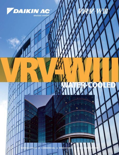
<strong>VRV</strong>-<strong>WIII</strong><br />
WATER-COOLED<br />
WATER-COOLED • COMMERCIAL • RENOVATION • NEW CONSTRUCTION
The water-cooled <strong>VRV</strong> ®<br />
(<strong>VRV</strong>-<strong>WIII</strong>) offers an<br />
energy saving alternative to traditional<br />
centralized equipment. Its remarkable<br />
compact and lightweight structure makes<br />
installation of <strong>VRV</strong> technology in large<br />
buildings possible. At only 330 lbs. and<br />
less than 40” high, the <strong>VRV</strong> ® -<strong>WIII</strong> can take<br />
a ride up the elevator to be installed in a<br />
plant room. This enhanced system offers<br />
state-of-the-art comfort for hotels, offices,<br />
and large commercial applications. The<br />
<strong>VRV</strong> system keeps running costs at an<br />
absolute minimum by controlling each zone<br />
individually and being able to shut down<br />
completely in unoccupied areas.<br />
ABSOLUTE COMFORT<br />
2 DAIKIN <strong>AC</strong>
The Water-Cooled Generation<br />
<strong>VRV</strong>-<strong>WIII</strong> systems are equivalent to 4-pipe chilled water systems, but also offer a viable<br />
alternative to Water-Source Heat Pump solutions. Each connected indoor unit can provide<br />
heating and cooling independently to suit zone requirements making these systems<br />
suitable for both open plan, or cellular applications with different operation requirements.<br />
<strong>VRV</strong>-<strong>WIII</strong> Features and Benefits<br />
Compact and lightweight<br />
Industry leading compact lightweight casing<br />
Height: 39-3/8”, Weight: 330 lbs. Install in a plant<br />
room, double-decker style if needed.<br />
Large capacity (6 to 21-Ton)<br />
Larger single system capacity ensures wider<br />
application range for satisfying floor-by-floor loads of<br />
commercial buildings.<br />
Lower condenser water temperature<br />
Continuous operation at 59°F entering condenser<br />
water temperature; intermittent operation as low as<br />
50°F thus suitable for low ambient temperature.<br />
Water side:<br />
Connecting to cooling<br />
tower and/or boiler<br />
combination or set up as<br />
geothermal<br />
Refrigerant side:<br />
Connects to <strong>Daikin</strong>’s lineup<br />
of <strong>VRV</strong> indoor units<br />
The <strong>VRV</strong>-<strong>WIII</strong> design is based on a modular design<br />
concept. It is composed of unified condensing units<br />
that require simply connecting a 2-pipe refrigerant<br />
network for heat pump applications or a 3-pipe<br />
refrigerant network for heat recovery applications.<br />
All water-cooled condensers are of the same<br />
dimensions, and are available in 6-Ton and 7-Ton.<br />
This is a simple system that allows manifolding<br />
together up to 3 condensers to form one system<br />
of up to 21-Ton (252 MBH). The condensers are<br />
designed for internal mounting only.<br />
The condensers are smaller and can be stacked,<br />
reducing the installation space and increasing the<br />
customers usable square footage.<br />
<strong>VRV</strong>-<strong>WIII</strong><br />
DAIKIN <strong>AC</strong> 3<br />
ABSOLUTE COMFORT
Why Select a <strong>VRV</strong>-<strong>WIII</strong> System?<br />
The top 5 reasons that make the solution a perfect fit<br />
1<br />
2<br />
3<br />
4<br />
5<br />
The efficiency and capacity of air-cooled systems reduce with extreme ambient conditions, causing<br />
systems to be oversized and increasing initial cost.<br />
Extreme piping lengths cause a capacity reduction; positioning <strong>VRV</strong>-<strong>WIII</strong> floor-by-floor reduces the<br />
capacity reduction and improves the efficiency of the system.<br />
Buildings with diverse loads will recover energy through the <strong>VRV</strong>-<strong>WIII</strong> system’s water loop, enhancing<br />
overall efficiency.<br />
Utilizing an existing condenser loop and associated heat rejection/injection reduces<br />
initial costs.<br />
Where geothermal efficiencies and benefits are desired, <strong>VRV</strong>-<strong>WIII</strong> is geothermal ready as standard.<br />
New Construction<br />
The <strong>VRV</strong>-<strong>WIII</strong> provides an energy efficient solution<br />
anywhere that could use a water-cooled chiller or<br />
replacing Water-Source Heat Pump design by enabling<br />
them to afford the water-cooled chiller benefits. It<br />
is especially true for high-rise buildings such as:<br />
• Condos<br />
• Offices<br />
New water-cooled solutions for all<br />
The general consensus was that water-cooled is only<br />
suitable for larger projects but that line of thinking<br />
is obsoleted with the <strong>VRV</strong>-<strong>WIII</strong>. The <strong>VRV</strong>-<strong>WIII</strong> proves<br />
itself a very competitive upgrade when replacing noisy<br />
Water-Source Heat Pump or rooftops with VAVs.<br />
<strong>VRV</strong>-<strong>WIII</strong> Unified Condensing Unit - Heat<br />
Recovery or Heat Pump from One Unit<br />
ABSOLUTE COMFORT<br />
• Medical Centers<br />
• Schools<br />
• In northern climates, <strong>VRV</strong>-<strong>WIII</strong> eliminates the low<br />
ambient heating and cooling concerns<br />
• Large building tenant fit outs: with <strong>VRV</strong>-<strong>WIII</strong>,<br />
the floors can now be leased as they are being<br />
completed in sequence<br />
• Add on new-build to existing campuses<br />
• Geothermal applications<br />
Retrofit<br />
Adding on to an existing water-cooled system or<br />
solving problem areas with <strong>VRV</strong>-<strong>WIII</strong> becomes a very<br />
easy, cost effective solution for applications such as<br />
hospitals, large business campuses, universities, office<br />
buildings, and factories.<br />
Also, the <strong>VRV</strong>-<strong>WIII</strong> can take advantage of an<br />
application with an existing 2-pipe chiller/boiler<br />
system with a condenser water loop.<br />
• Connect two pipes = Heat Pump<br />
• Connect three pipes + Branch Selector boxes =<br />
Heat Recovery<br />
• The water loop can be designed for maximum<br />
anticipated installed load.<br />
Benefits<br />
• Lower initial cost for the developer/builder<br />
• Client or developer can add air conditioning to<br />
match load requirements<br />
• No rebalancing of water systems if commissioning<br />
valves are installed on each floor<br />
• Connects to the full suite of advanced <strong>Daikin</strong><br />
control solutions including Intelligent Touch<br />
Controller and I-Manager III<br />
• Can be integrated to open protocol building<br />
management systems via the <strong>Daikin</strong> B<strong>AC</strong>net ® and<br />
Lo nWo r k s ® interfaces<br />
4 DAIKIN <strong>AC</strong>
Outstanding performance for cold climate applications<br />
<strong>VRV</strong>-<strong>WIII</strong> Condensing Units RWEYQ<br />
Utilizing <strong>VRV</strong>-<strong>WIII</strong> eliminates the ambient operation range<br />
limitation and the associated capacity and efficiency<br />
reduction (up to 30%) of air-cooled systems. This solution<br />
can result in smaller capacity equipment (reducing initial<br />
costs) and eliminates the need for a secondary heating<br />
source at the indoor units and their associated fuel/power<br />
supply.<br />
Minimal to no ventilation is required for the heat<br />
rejection of the condensers which reduces installation<br />
cost (the installed location must be kept between 32°F<br />
and 104°F).<br />
<strong>VRV</strong>-<strong>WIII</strong> connects to a closed-loop cooling tower and<br />
boiler, or in a geothermal configuration.<br />
The <strong>VRV</strong>-<strong>WIII</strong> (unified heat pump or heat recovery<br />
condensing unit) allows for continuous operation<br />
even in cold climates delivering comfortable heating<br />
performance with no defrost. The system’s brazed<br />
plate heat exchanger can tolerate water pressure up to<br />
285 psi (or 640ft. of head) and has modular units that<br />
can be interconnected to make combinations of up to<br />
21-Tons.<br />
Standard <strong>VRV</strong>-<strong>WIII</strong> Specification<br />
Specification<br />
Application Rules<br />
Water Flow Rate (minimum)<br />
16.4 – 39.5 (13.2) gpm<br />
[62 – 150 (50) l/m]<br />
Water Temp Range Cooling (intermittent) 59 – 113°F (50°F) [15 - 45°C]<br />
Water Temp Range Heating (intermittent) 59 – 113°F (50°F) [15 - 45°C]<br />
Water Temp Range Simultaneous<br />
Cooling & Heating (intermittent)<br />
59 – 113°F (50°F) [15 - 45°C]<br />
Glycol Allowance 0 – 40%<br />
Glycol Type<br />
Propylene / Ethylene<br />
Connection Ratio 50 – 130%<br />
<strong>VRV</strong>-<strong>WIII</strong> Geothermal Configuration<br />
With addition of the newly developed <strong>VRV</strong>-<strong>WIII</strong> geothermal control logic, the operation range can now be<br />
extended to as low as 14°F (-10°C) entering water temperature (EWT) in heating. Contact your local <strong>Daikin</strong><br />
office for more details.<br />
Geothermal applications are available for single module systems.<br />
Geothermal Enhanced <strong>VRV</strong>-<strong>WIII</strong> Specification<br />
Specification<br />
Water Flow Rate<br />
Water Temp Range Cooling (intermittent)<br />
Water Temp Range Heating<br />
Application Rules<br />
21 – 40 gpm<br />
[80 – 150 l/m]<br />
50 – 113°F (43°F) [6 - 45°C]<br />
14 – 113°F [-10 - 45°C]<br />
Water Temp Range Simultaneous<br />
50 – 113°F (43°F) [6 - 45°C]*<br />
Cooling & Heating (intermittent)<br />
Glycol Requirement 30 – 45%**<br />
Glycol Type<br />
Ethylene<br />
Connection Ratio 50 – 100%<br />
* EWT in simultaneous heating and cooling operation can be lower than 43°F if<br />
the condenser is in heating dominant heat recovery operation<br />
(contact your local <strong>Daikin</strong> office for further details)<br />
** EWT operation range is limited to 23°F (-5°C) with 30% glycol, 40-45% glycol<br />
must be used with water temperatures below 23°F down to a limit of 14°F<br />
<strong>VRV</strong>-<strong>WIII</strong><br />
DAIKIN <strong>AC</strong> 5<br />
ABSOLUTE COMFORT
Water-Side Infrastructure<br />
& Components<br />
• A water loop system is routed around the building,<br />
either vertically or horizontally.<br />
• Heat injection (boilers) and rejection (cooling tower<br />
or dry coolers) are required to ensure that the water<br />
loop stays between the required design conditions<br />
of 50 and 113°F.<br />
• Can connect to geothermal water loop as standard<br />
• <strong>VRV</strong>-<strong>WIII</strong> condensers are connected to the water<br />
loop and the connecting refrigerant circuit serves<br />
indoor units the same as any air-cooled <strong>VRV</strong> system.<br />
• The following water side components are required:<br />
u Strainer (mandatory – supplied with each<br />
condensing unit)<br />
u Flow switch or differential pressure switch<br />
(Essential)<br />
u Thermostat (for water temperature)<br />
u Circulation pumps<br />
u Adjustable flange<br />
Example of layout when used in combination with boiler and cooling tower<br />
Pump connections and interlock function<br />
Pump Connections<br />
Interlock Circuit<br />
ABSOLUTE COMFORT<br />
It is possible to interlink the operation of the water<br />
circulation pumps with the operation of the <strong>VRV</strong>-<strong>WIII</strong><br />
condensing unit.<br />
• A set of terminals are provided on the condensing<br />
unit terminal X2M rated at 240V<strong>AC</strong>, up to 0.5A.<br />
• This terminal can be used to power a relay to start<br />
the pumps.<br />
• In manifolded condensing unit installations (e.g.<br />
RWEYQ216PTJU), a group control PCB (DTA104A62)<br />
can be used because a set of terminals on this<br />
accessory provides the pump operation signal when<br />
any condensing unit is in operation. The X2M<br />
terminals will not be used in this instance.<br />
• An interlock circuit needs to be connected to the<br />
terminals of X3M of every condensing unit to allow<br />
the system to operate. This interlock can be a flow<br />
or differential pressure switch (to ensure water is<br />
flowing before operation starts). Terminals X3M are<br />
rated at 15VDC 1mA.<br />
• In manifolded condensing unit installations (e.g.<br />
RWEYQ216PTJU), by installing a group control<br />
PCB, DTA104A62, the flow switch needs to be<br />
connected to the master condensing unit only.<br />
6 DAIKIN <strong>AC</strong>
Minimizing Energy Consumption<br />
kW/year<br />
Energy Savings Impact<br />
2,500<br />
2,000<br />
1,500<br />
1,000<br />
500<br />
(100)<br />
(65)<br />
Example of savings if introducing<br />
pump control on floor by floor basis<br />
35% energy savings<br />
Example of savings if introducing<br />
pump control local to the condensing<br />
unit and adopting VFD type pumps<br />
62% energy savings<br />
Example of savings if local pump<br />
control, usage of VFD pumps and<br />
local modulating valves<br />
75% energy savings<br />
(38)<br />
(25)<br />
Did you know?<br />
<strong>VRV</strong>-<strong>WIII</strong> systems placed in<br />
service during the tax year that<br />
was acquired after October<br />
3, 2008 may be eligible for<br />
a geothermal system 10%<br />
investment US federal tax<br />
credit when using the ground<br />
or ground water as a thermal<br />
energy source. For the tax<br />
credit details and instructions<br />
for claiming the credit, please<br />
see IRS Form 3468.<br />
0<br />
No flow rate control<br />
(Entire building)<br />
No flow rate control<br />
(Floor by floor)<br />
Control at each unit<br />
(On-Off control)<br />
Control at each unit<br />
(Modulation control)<br />
High energy efficiencies result from<br />
2-stage heat recovery<br />
<strong>VRV</strong>-<strong>WIII</strong> benefits from a 2-stage heat recovery<br />
capability. The first stage (stage 1) is achieved within<br />
the refrigerant system and applies to heat recovery units<br />
only. Heat exhausted from indoor units in cooling mode<br />
is merely transferred to units in areas requiring heating,<br />
maximizing energy efficiency and reducing electricity<br />
consumption.<br />
Heat recovery also available on heat pump<br />
units through the water loop<br />
Second stage (stage 2) heat recovery is achieved within<br />
the water loop between the water-cooled condensing<br />
units. Two-stage heat recovery substantially improves<br />
efficiency and represents an ideal solution to the<br />
requirements of modern office buildings, in which<br />
some areas require cooling even in winter, depending<br />
on the degree of sunshine at the time, the number of<br />
individuals in the room, and the application.<br />
Stage 2<br />
Stage 1<br />
<strong>VRV</strong>-<strong>WIII</strong><br />
DAIKIN <strong>AC</strong> 7<br />
ABSOLUTE COMFORT
Versatile Piping Design<br />
Versatile water piping<br />
<strong>VRV</strong>-<strong>WIII</strong> uses water as its heat source, so it is optimal<br />
for large buildings, including tall, multi-story buildings,<br />
because the system can tolerate water pressure of up to<br />
285 psi (or 640 ft. of head).<br />
Furthermore, if the currently installed heat source’s water<br />
temperature is between 50°F and 113°F, it may be<br />
possible to use the existing water pipe work and heat<br />
source. This alone makes it an ideal system solution for<br />
building refurbishment projects.<br />
Because the system is water-cooled, outdoor air<br />
temperature does not affect its heating capacity. In<br />
addition, water-cooling means no defrost operation<br />
is required, and the resultant rapid start-up time<br />
assures quick and comfortable heating, even in cold<br />
environments.<br />
Long refrigerant piping length<br />
Considerable flexibility is available within the refrigerant<br />
circuit since up to 980ft. actual piping length and 164ft.<br />
(if the <strong>VRV</strong>-<strong>WIII</strong> condensing unit is above the indoor unit)<br />
in height can exist between the <strong>VRV</strong>-<strong>WIII</strong> condensing<br />
units and indoor units. Water piping does not intrude in<br />
the occupied spaces, so there are no potential leakage<br />
problems.<br />
Actual piping length between the<br />
<strong>VRV</strong>-<strong>WIII</strong> and indoor units:<br />
390ft. (equivalent piping length: 459ft.)<br />
Indoor installation of condensing unit<br />
Water piping length<br />
depends on the heat<br />
source equipment<br />
Water piping<br />
Refrigerant piping<br />
Level difference between<br />
indoor units: 49ft.<br />
Level difference between the<br />
<strong>VRV</strong>-<strong>WIII</strong> and indoor units:<br />
164ft. if the <strong>VRV</strong>-<strong>WIII</strong> is above<br />
130ft. if the <strong>VRV</strong>-<strong>WIII</strong> is below<br />
Refrigerant piping specifications<br />
Ft.<br />
Linear piping between condensing unit and furthest located fan coil<br />
unit (equivalent)<br />
390 (459)<br />
Total “one-way” piping in the complete piping network 980<br />
Vertical (height) separation between the condensing unit and the<br />
fan coil units (if condensing unit is below)*<br />
164 (130)<br />
Vertical (height) separation between fan coil units 49<br />
Linear piping between 1st REFNET and furthest located fan coil unit 130<br />
*For geothermal applications, if the condenser is lower than the indoor units,<br />
the maximum vertical separation is 65 ft.<br />
The <strong>VRV</strong>-<strong>WIII</strong> now allows for a functional, easy-to-install<br />
water-cooled solution into smaller applications. The<br />
systems fit very well in tall/large buildings however it is<br />
also a perfect fit for a smaller job where the installation<br />
of a chiller is cost prohibitive.<br />
ABSOLUTE COMFORT<br />
8 DAIKIN <strong>AC</strong>
<strong>VRV</strong> Indoor Units<br />
Indoor Type<br />
Vertical air handling unit<br />
(horizontal right<br />
configuration is possible)<br />
Capacity Range<br />
MBH 7.5 09 12 18 24 30 36 42 48 54 72 96<br />
Tons 0.6 0.75 1 1.5 2 2.5 3 3.5 4 4.5 6 8<br />
FXTQ_PAVJU<br />
OSA OSA OSA OSA<br />
OSA OSA OSA OSA<br />
FXMQ_PVJU<br />
DC ducted concealed<br />
ceiling (medium static)<br />
Ducted<br />
FXMQ_MVJU<br />
OSA<br />
OSA<br />
OSA<br />
OSA<br />
OSA<br />
OSA<br />
OSA<br />
OSA<br />
Concealed ceiling unit<br />
(medium static)<br />
OSA<br />
OSA<br />
FXDQ_MVJU<br />
Slim duct built-in<br />
concealed ceiling unit<br />
OSA<br />
OSA<br />
OSA<br />
OSA<br />
OSA<br />
FXFQ_PVJU<br />
Round flow ceiling<br />
mounted cassette<br />
OSA<br />
OSA<br />
OSA<br />
OSA<br />
OSA<br />
OSA<br />
OSA<br />
FXZQ_M7VJU<br />
2’ x 2’ 4-way ceiling<br />
mounted cassette<br />
OSA<br />
OSA<br />
OSA<br />
OSA<br />
FXAQ_MVJU<br />
Wall mounted unit<br />
Duct-free<br />
Ceiling suspended unit<br />
FXHQ_MVJU<br />
FXLQ_MVJU<br />
Floor standing unit<br />
FXNQ_MVJU<br />
Concealed floor standing<br />
unit<br />
OSA<br />
OSA<br />
OSA<br />
Ventilation<br />
OSA<br />
100% Outside Air<br />
Processing Unit<br />
Available (11 types, 51 models)<br />
Condensate pump standard on model<br />
FXMQ_MFVJU<br />
Outside air connection possible on model<br />
OSA<br />
OSA OSA<br />
<strong>VRV</strong>-<strong>WIII</strong><br />
DAIKIN <strong>AC</strong> 9<br />
ABSOLUTE COMFORT
<strong>VRV</strong>-<strong>WIII</strong> Specifications<br />
Single module system<br />
<strong>VRV</strong>-<strong>WIII</strong> - Unified Heat Pump and Heat Recovery 6-Ton 7-Ton<br />
Model Name RWEYQ72PTJU RWEYQ84PTJU<br />
Cooling Capacity 1 Btu/h 72,000 84,000<br />
Rated Full Load EER* 15.3 13.7<br />
Cooling Input Power kW 4.2 5.6<br />
Performance<br />
Heating Capacity 2 Btu/h 81,000 94,000<br />
Rated Full Load COP* 5.3 4.7<br />
Heating Input Power kW (Btu/h) 4.0 (13,648) 5.4 (18,425)<br />
Power V/Ph/Hz 208-230/3/60 208-230/3/60<br />
Sound Pressure Level @ 3ft. dB(A) 50 51<br />
System Configuration Heat Pump Heat Recovery Heat Pump Heat Recovery<br />
Liquid Pipe (Main Line) in. 3/8 3/8 3/8 3/8<br />
Suction Gas Pipe (Main Line) in. N/A 3/4 N/A 7/8<br />
Refrigerant Piping Discharge Gas Pipe (Main Line) in. 3/4 5/8 7/8 3/4<br />
Vertical Pipe Length (if unit is below FCU) ft. 164 (130) 164 (130)<br />
Actual Pipe Length (Equivalent Length) ft. 390 (459) 390 (459)<br />
Total Pipe Length ft. 980 980<br />
Connection Ratio<br />
Standard Connectable Indoor Unit Ratio (geothermal) % 50 - 130 (50 - 100) 50 - 130 (50 - 100)<br />
Maximum Number of Indoor Units Qty. 12 14<br />
BPHE Inlet Pipe (Female Thread) in. 1 1/4FPT 1 1/4FPT<br />
BPHE Outlet Pipe (Female Thread) in. 1 1/4FPT 1 1/4FPT<br />
Water Side<br />
Drain Pipe (Female Thread) in. 1/2FPS 1/2FPS<br />
Maximum System Water Pressure (BPHE) psi 285 285<br />
Inlet Water Temperature Range (intermittent) °F 59 - 113 (50) 59 - 113 (50)<br />
Recommended Inlet Water Flow Rate per Module (min.) gpm 16.4 ~ 39.5 (13.2) 16.4 ~ 39.5 (13.2)<br />
Unit<br />
Weight lbs. 330 330<br />
Dimensions (H x W x D) in. 39 3/8 x 30 3/4 x 21 11/16<br />
Voltage Range (min.-max.) V 187-253 187-253<br />
Electrical<br />
Maximum Overcurrent Protection (MOP) A 40.0 40.0<br />
Minimum Circuit Amps (MCA) A 22.4 22.4<br />
Compressor Rated Load Amps (RLA) A 11.6 15.4<br />
Compressor Type <strong>Daikin</strong> G-Type Scroll <strong>Daikin</strong> G-Type Scroll<br />
Compressor Compressor Set-up 1 INV 1 INV<br />
Compressor Capacity Control % 23 - 100 23 - 100<br />
1 Indoor temp. : 80°FDB, 67°FWB/inlet water temp. : 85°F/outlet water temp. : 95°F Equivalent piping length : 25ft, level difference : 0ft.<br />
2 Indoor temp. : 70°FDB, 60°FWB/inlet water temp. : 70°F/Equivalent piping length : 25ft, level difference : 0ft.<br />
*The tested system EER and COP values reflect “full load” efficiency only<br />
and are the results from testing to the “Alternate Test Method” (ATM)<br />
guidelines provided by the U.S. Department of Energy (DOE) in the Federal<br />
Register / Vol. 74, No. 68 / Friday April 10, 2009 / Notices / Pages 16373 –<br />
16377. All tested values surpass the minimum efficiency levels regulated in<br />
the DOE Code of Federal Regulation 10 CFR Ch. II § 431.97.<br />
Testing was performed at full load capacity with a ducted indoor unit configuration to determine only the Energy Efficiency Ratio (EER) and Coefficient<br />
Of Performance (COP) as specified from the DOE in the ATM guidelines. A <strong>VRV</strong> ® -<strong>WIII</strong> system is a system that is constantly modulating its operation, via<br />
its intelligent Inverter Compressor Technology and Electronic Expansion Valves, to satisfy the ever changing load requirements of the buildings they serve.<br />
Although EER and COP are a common metric for comparing efficiencies, they do not fully qualify the expected performance as the majority of operating<br />
hours are in part load operation. However, at this time no official testing and rating program to quantify the part load efficiency (such as iPLV) of a <strong>VRV</strong>-<strong>WIII</strong><br />
system is recognized by the DOE.<br />
ABSOLUTE COMFORT<br />
10 DAIKIN <strong>AC</strong>
<strong>VRV</strong>-<strong>WIII</strong> Specifications<br />
Double module system<br />
<strong>VRV</strong>-<strong>WIII</strong> - Unified Heat Pump and Heat Recovery 12-Ton 14-Ton<br />
Model<br />
Name RWEYQ144PTJU RWEYQ168PTJU<br />
Combination 2 x RWEYQ72PTJU 2 x RWEYQ84PTJU<br />
Cooling Capacity 1 Btu/h 144,000 168,000<br />
Rated Full Load EER* 15.3** 13.7**<br />
Cooling Input Power kW 8.4 11.2<br />
Performance<br />
Heating Capacity 2 Btu/h 162,000 189,000<br />
Rated Full Load COP* 5.3** 4.7**<br />
Heating Input Power kW (Btu/h) 8.0 (27,296) 10.8 (36,850)<br />
Power V/Ph/Hz 208-230/3/60 208-230/3/60<br />
Sound Pressure Level @ 3ft. dB(A) 53 54<br />
System Configuration Heat Pump Heat Recovery Heat Pump Heat Recovery<br />
Liquid Pipe (Main Line) in. 1/2 1/2 5/8 5/8<br />
Suction Gas Pipe (Main Line) in. N/A 1 1/8 N/A 1 1/8<br />
Refrigerant Piping Discharge Gas Pipe (Main Line) in. 1 1/8 7/8 1 1/8 7/8<br />
Vertical Pipe Length (if unit is below FCU) ft. 164 (130) 164 (130)<br />
Actual Pipe Length (Equivalent Length) ft. 390 (459) 390 (459)<br />
Total Pipe Length ft. 980 980<br />
Connection Ratio<br />
Standard Connectable Indoor Unit Ratio % 50 - 130 50 - 130<br />
Maximum Number of Indoor Units Qty. 20 20<br />
BPHE Inlet Pipe (Female Thread) in. 2 x (1 1/4FPT) 2 x (1 1/4FPT0<br />
BPHE Outlet Pipe (Female Thread) in. 2 x (1 1/4FPT) 2 x (1 1/4FPT)<br />
Water Side<br />
Drain Pipe (Female Thread) in. 2 x (1/2FPS) 2 x (1/2FPS)<br />
Maximum System Water Pressure (BPHE) psi 285 285<br />
Inlet Water Temperature Range (intermittent) °F 59 - 113 (50) 59 - 113 (50)<br />
Recommended Inlet Water Flow Rate per Module (min.) gpm 16.4 ~ 39.5 (13.2) 16.4 ~ 39.5 (13.2)<br />
Unit<br />
Weight lbs. 2 x 330 2 x 330<br />
Dimensions (H x W x D) in. 39 3/8 x (30 3/4 x 2) x 21 11/16<br />
Voltage Range (min.-max.) V 187-253 187-253<br />
Electrical<br />
Maximum Overcurrent Protection (MOP) A 40 + 40 40 + 40<br />
Minimum Circuit Amps (MCA) A 22.4 + 22.4 22.4 + 22.4<br />
Compressor Rated Load Amps (RLA) A 11.6 + 11.6 15.4 + 15.4<br />
Compressor Type <strong>Daikin</strong> G-Type Scroll <strong>Daikin</strong> G-Type Scroll<br />
Compressor Compressor Set-up 1 INV + 1 INV 1 INV + 1 INV<br />
Compressor Capacity Control % 11 - 100 11 - 100<br />
1 Indoor temp. : 80°FDB, 67°FWB/inlet water temp. : 85°F/outlet water temp. : 95°F Equivalent piping length : 25ft, level difference : 0ft.<br />
2 Indoor temp. : 70°FDB, 60°FWB/inlet water temp. : 70°F/Equivalent piping length : 25ft, level difference : 0ft.<br />
*The tested system EER and COP values reflect “full load” efficiency only<br />
and are the results from testing to the “Alternate Test Method” (ATM)<br />
guidelines provided by the U.S. Department of Energy (DOE) in the Federal<br />
Register / Vol. 74, No. 68 / Friday April 10, 2009 / Notices / Pages 16373 –<br />
16377. All tested values surpass the minimum efficiency levels regulated in<br />
the DOE Code of Federal Regulation 10 CFR Ch. II § 431.97.<br />
**There is no minimum efficiency defined in 10 CFR Ch. II § 431.97 for<br />
Water Cooled Packaged equipment greater than 135,000 Btu/hr.<br />
Testing was performed at full load capacity with a ducted indoor unit configuration to determine only the Energy Efficiency Ratio (EER) and Coefficient<br />
Of Performance (COP) as specified from the DOE in the ATM guidelines. A <strong>VRV</strong> ® -<strong>WIII</strong> system is a system that is constantly modulating its operation, via<br />
its intelligent Inverter Compressor Technology and Electronic Expansion Valves, to satisfy the ever changing load requirements of the buildings they serve.<br />
Although EER and COP are a common metric for comparing efficiencies, they do not fully qualify the expected performance as the majority of operating<br />
hours are in part load operation. However, at this time no official testing and rating program to quantify the part load efficiency (such as iPLV) of a <strong>VRV</strong>-<strong>WIII</strong><br />
system is recognized by the DOE.<br />
<strong>VRV</strong>-<strong>WIII</strong><br />
DAIKIN <strong>AC</strong> 11<br />
ABSOLUTE COMFORT
<strong>VRV</strong>-<strong>WIII</strong> Specifications<br />
Triple module system<br />
<strong>VRV</strong>-<strong>WIII</strong> - Unified Heat Pump and Heat Recovery 18-Ton 21-Ton<br />
Model<br />
Name RWEYQ216PTJU RWEYQ252PTJU<br />
Combination 3 x RWEYQ72PTJU 3 x RWEYQ84PTJU<br />
Cooling Capacity 1 Btu/h 216,000 252,000<br />
Rated Full Load EER* 15.3** 13.7**<br />
Cooling Input Power kW 12.6 16.8<br />
Performance<br />
Heating Capacity 2 Btu/h 243,000 283,500<br />
Rated Full Load COP* 5.3** 4.7**<br />
Heating Input Power kW (Btu/h) 12.0 (40,944) 16.2 (55,274)<br />
Power V/Ph/Hz 208-230/3/60 208-230/3/60<br />
Sound Pressure Level @ 3ft. dB(A) 56 57<br />
System Configuration Heat Pump Heat Recovery Heat Pump Heat Recovery<br />
Liquid Pipe (Main Line) in. 5/8 5/8 3/4 3/4<br />
Suction Gas Pipe (Main Line) in. N/A 1 3/8 N/A 1 3/8<br />
Refrigerant Piping Discharge Gas Pipe (Main Line) in. 1 3/8 1 1/8 1 3/8 1 1/8<br />
Vertical Pipe Length (if unit is below FCU) ft. 164 (130) 164 (130)<br />
Actual Pipe Length (Equivalent Length) ft. 390 (459) 390 (459)<br />
Total Pipe Length ft. 980 980<br />
Connection Ratio<br />
Standard Connectable Indoor Unit Ratio % 50 - 130 50 - 130<br />
Maximum Number of Indoor Units Qty. 22 32<br />
BPHE Inlet Pipe (Female Thread) in. 3 x (1 1/4FPT) 3 x (1 1/4FPT)<br />
BPHE Outlet Pipe (Female Thread) in. 3 x (1 1/4FPT) 3 x (1 1/4FPT)<br />
Water Side<br />
Drain Pipe (Female Thread) in. 3 x (1/2FPS) 3 x (1/2FPS)<br />
Maximum System Water Pressure (BPHE) psi 285 285<br />
Inlet Water Temperature Range (intermittent) °F 59 - 113 (50) 59 - 113 (50)<br />
Recommended Inlet Water Flow Rate per Module (min.) gpm 16.4 ~ 39.5 (13.2) 16.4 ~ 39.5 (13.2)<br />
Unit<br />
Weight lbs. 3 x 330 3 x 330<br />
Dimensions (H x W x D) in. 39 3/8 x (30 3/4 x 3) x 21 11/16<br />
Voltage Range (min.-max.) V 187-253 187-253<br />
Electrical<br />
Maximum Overcurrent Protection (MOP) A 40 + 40 + 40 40 + 40 + 40<br />
Minimum Circuit Amps (MCA) A 22.4 + 22.4 + 22.4 22.4 + 22.4 + 22.4<br />
Compressor Rated Load Amps (RLA) A 11.6 + 11.6 + 11.6 15.4 + 15.4 + 15.4<br />
Compressor Type <strong>Daikin</strong> G-Type Scroll <strong>Daikin</strong> G-Type Scroll<br />
Compressor Compressor Set-up 1 INV + 1 INV + 1 INV 1 INV + 1 INV + 1 INV<br />
Compressor Capacity Control % 8 - 100 8 - 100<br />
1 Indoor temp. : 80°FDB, 67°FWB/inlet water temp. : 85°F/outlet water temp. : 95°F Equivalent piping length : 25ft, level difference : 0ft.<br />
2 Indoor temp. : 70°FDB, 60°FWB/inlet water temp. : 70°F/Equivalent piping length : 25ft, level difference : 0ft.<br />
*The tested system EER and COP values reflect “full load” efficiency only<br />
and are the results from testing to the “Alternate Test Method” (ATM)<br />
guidelines provided by the U.S. Department of Energy (DOE) in the Federal<br />
Register / Vol. 74, No. 68 / Friday April 10, 2009 / Notices / Pages 16373 –<br />
16377. All tested values surpass the minimum efficiency levels regulated in<br />
the DOE Code of Federal Regulation 10 CFR Ch. II § 431.97.<br />
**There is no minimum efficiency defined in 10 CFR Ch. II § 431.97 for<br />
Water Cooled Packaged equipment greater than 135,000 Btu/hr.<br />
Testing was performed at full load capacity with a ducted indoor unit configuration to determine only the Energy Efficiency Ratio (EER) and Coefficient<br />
Of Performance (COP) as specified from the DOE in the ATM guidelines. A <strong>VRV</strong> ® -<strong>WIII</strong> system is a system that is constantly modulating its operation, via<br />
its intelligent Inverter Compressor Technology and Electronic Expansion Valves, to satisfy the ever changing load requirements of the buildings they serve.<br />
Although EER and COP are a common metric for comparing efficiencies, they do not fully qualify the expected performance as the majority of operating<br />
hours are in part load operation. However, at this time no official testing and rating program to quantify the part load efficiency (such as iPLV) of a <strong>VRV</strong>-<strong>WIII</strong><br />
system is recognized by the DOE.<br />
ABSOLUTE COMFORT<br />
12 DAIKIN <strong>AC</strong>
40<br />
<strong>VRV</strong>-<strong>WIII</strong> Installation Space<br />
2<br />
60<br />
5<br />
1<br />
40<br />
3<br />
40<br />
4<br />
60<br />
60<br />
60<br />
2<br />
(in.)<br />
1<br />
[3]<br />
13/16 30-11/16 13/16<br />
13-3/4<br />
6<br />
35-7/16<br />
8<br />
7<br />
15-3/8 9<br />
21-5/8 19-11/16<br />
2<br />
7 7<br />
9 9<br />
8 8<br />
6 6<br />
35-7/16 19-11/16<br />
13/16 13/16 13/16<br />
10<br />
[4]<br />
13-3/4<br />
9-13/16<br />
9<br />
5<br />
39-3/8<br />
11-13/16<br />
8<br />
3-15/16<br />
1. Indoor unit<br />
2. Branch switch, overcurrent breaker<br />
3. Remote controller<br />
4. Cool/heat selector<br />
5. Personal computer or radio<br />
1. In case of a single installation [inch.]<br />
2. In case of multiple unit installation [inch.]<br />
3. Top view<br />
4. Side view<br />
5. Condensing unit<br />
6. Service Space (front side)<br />
7. Service Space (back side)<br />
8. Space for installing water piping secure enough space for<br />
removing the front panel.<br />
9. Ventilation Space above the area ( ) of the condensing unit.<br />
10. Secure spaces in the front, back and top sides as same as the<br />
case of single installation.<br />
<strong>VRV</strong>-<strong>WIII</strong> Accessories<br />
Branch Selector Units (for use with heat recovery configuration)<br />
Model Name BSVQ36PVJU BSVQ60PVJU BSVQ96PVJU<br />
Power Supply V/ph/Hz 208-230/1/60<br />
Total Capacity Index of Connectable Indoor Units Less than 36 Less than 60 Less than 96<br />
Number of Connectable Indoor Units Max. 5 Max. 8 Max. 8<br />
Casing<br />
Galvanized Steel Plate<br />
Dimensions (H x W x D) in. 8 1/8 x 15 1/4 x 12 13/16 8 1/8 x 15 1/4 x 12 13/16 8 3/16 x 15 5/16 x 12 7/8<br />
Foamed Polyurethane, Foamed Polyurethane, Foamed Polyurethane,<br />
Sound Absorbing Thermal Insulation Material<br />
Frame Resisting Needle Felt Frame Resisting Needle Felt Frame Resisting Needle Felt<br />
Indoor Liquid Pipes in. ø 3/8 (Braze) 1 ø 3/8 (Braze) ø 3/8 (Braze)<br />
Piping<br />
Connections<br />
Unit Gas Pipes in. ø 5/8 (Braze) 1 ø 5/8 (Braze) 2 ø 7/8 (Braze)<br />
Outdoor<br />
Unit<br />
Liquid Pipes in. ø 3/8 (Braze) ø 3/8 (Braze) ø 3/8 (Braze)<br />
Suction Gas Pipes in. ø 5/8 (Braze) ø 5/8 (Braze) 2 ø 7/8 (Braze)<br />
Discharge Gas Pipes in. ø 1/2 (Braze) ø 1/2 (Braze) 2 ø 3/4 (Braze)<br />
Weight lbs. 26 26 33<br />
Note:<br />
1<br />
In case of connecting with a 07-18 type indoor unit, match to the size of field pipe using the attached pipe.<br />
(Connection between the attached pipe and the field pipe must be brazed.)<br />
2<br />
In case of connecting with indoor unit capacity index 54 or more and 60 or less, match the size of the field pipe using the attached pipe.<br />
(Connection between the attached pipe and the field pipe must be brazed.)<br />
<strong>VRV</strong>-<strong>WIII</strong> Accessories<br />
Model Name<br />
Cool/Heat Selector (requires ABC terminal kit)<br />
Fixing box<br />
REFNET ® header<br />
Distribution piping<br />
REFNET ® joint<br />
Condensing unit multi connection piping<br />
kit (heat pump)<br />
Condensing unit multi connection piping<br />
kit (heat recovery)<br />
External control adapter for condensing unit<br />
RWEYQ72PTJU RWEYQ144PTJU RWEYQ216PTJU<br />
RWEYQ84PTJU RWEYQ168PTJU RWEYQ252PTJU<br />
KRC19-26A6<br />
KJB111A<br />
KHRP25M33H (Max. 8 branch)<br />
KHRP26M22H (Max. 4 branch)<br />
KHRP26M33H (Max. 8 branch)<br />
KHRP25M22T<br />
KHRP25M33T<br />
KHRP26M22T<br />
KHRP26M33T<br />
KHRP25M33H (Max. 8 branch)<br />
KHRP25M72H (Max. 8 branch)<br />
KHRP26M22H (Max. 4 branch)<br />
KHRP26M33H (Max. 8 branch)<br />
KHRP26M72H (Max. 8 branch)<br />
KHRP25M22T<br />
KHRP25M33T<br />
KHRP25M72TU<br />
KHRP26M22T<br />
KHRP26M33T<br />
KHRP26M72TU<br />
KHRP25M33H (Max. 8 branch)<br />
KHRP25M72H (Max. 8 branch)<br />
KHRP25M73HU (Max. 8 branch)<br />
KHRP26M22H (Max. 4 branch)<br />
KHRP26M33H (Max. 8 branch)<br />
KHRP26M72H (Max. 8 branch)<br />
KHRP26M73HU (Max. 8 branch)<br />
KHRP25M22T<br />
KHRP25M33T<br />
KHRP25M72TU<br />
KHRP25M73TU<br />
KHRP26M22T<br />
KHRP26M33T<br />
KHRP26M72TU<br />
KHRP26M73TU<br />
- BHFP22MA56U BHFP22MA84U<br />
- BHFP26MA56U BHFP26MA84U<br />
DTA104A62<br />
<strong>VRV</strong>-<strong>WIII</strong><br />
DAIKIN <strong>AC</strong> 13<br />
ABSOLUTE COMFORT
<strong>VRV</strong> Controls<br />
Choosing the right controls<br />
Unless it is controlled, managed and operated in an appropriate manner, a high-performing<br />
system will not be able to provide the energy-efficiency or comfort it claims. Promoting the<br />
systemization of control management not only improves efficiency, but also represents a<br />
number of possibilities in terms of convenience. <strong>Daikin</strong>’s line up of intelligent controls gives<br />
the user the ability to address all needs in one package and one supplier: <strong>Daikin</strong>.<br />
<strong>Daikin</strong> controls are optimized for <strong>VRV</strong> technology and offers highly scalable solutions for all applications and<br />
budgets. It also allows for lower cost alternatives to traditional energy management systems when centralized<br />
control is required.<br />
Project Requirements<br />
<strong>Daikin</strong> <strong>VRV</strong> Controls<br />
Simple individual zone control<br />
BRC1E71<br />
Navigation<br />
BRC2A71<br />
Simplified<br />
DCS302C71<br />
Centralized<br />
DCS301C71<br />
Unified<br />
DCS601C71<br />
Intelligent Touch<br />
Intelligent<br />
Manager<br />
B<strong>AC</strong>net<br />
Interface<br />
Lo nWorks<br />
Interface<br />
Individual zone control with 7-day programmable scheduling<br />
Multi-zone control without scheduling functions<br />
Basic central point on/off control of all air handling units<br />
Advanced multi-zone control of small to medium size projects<br />
Advanced multi-zone control of large commercial projects<br />
Advanced multi-zone control with scheduling logic and calender<br />
Automatic cooling/heating changeover for heat pump systems<br />
Single input batch shutdown of all connected air handlers<br />
Web browser control and monitoring via Intranet and Internet<br />
E-mail notification of system alarms and equipment malfunctions<br />
Multiple tenant power billing for shared condenser applications<br />
Temperature set-point range restrictions<br />
Graphical user interface based upon a PC platform<br />
Start/stop control of ancillary building systems 1<br />
<strong>Daikin</strong> <strong>VRV</strong> integration with B<strong>AC</strong>net based automation systems<br />
<strong>Daikin</strong> <strong>VRV</strong> integration with Lo nWorks based automation systems<br />
ABSOLUTE COMFORT<br />
1<br />
Requires one or more DEC102A51-US2 Digital Input/Output units.<br />
Native application or feature for this device.<br />
Dependent upon capabilities of the third party energy management system.<br />
14 DAIKIN <strong>AC</strong>
Controls that offer freedom to administrators<br />
Freedom to control the air-conditioning system, via the Internet, from home or any other location with a PC.<br />
Should a malfunction occur, a notification is sent by e-mail to a cell phone or PC (any e-mail address specified by<br />
the user). This gives administrators the freedom to leave the room/building where the controller is located.<br />
DCS601C71<br />
• 64 groups (128 indoor units) connectable<br />
• Management of <strong>Daikin</strong> units and ancillary equipment<br />
• Touch screen display<br />
• Built-in Ethernet port, Web enabled (optional)<br />
• Alarm e-mail function<br />
IMP-128/256/512/768/1,024<br />
• 1,024 indoor units<br />
(organized in up to 200 control groups)<br />
• Management of <strong>Daikin</strong> units and ancillary equipment<br />
• Operation on one master PC and one sub PC<br />
(sub PC option)<br />
• Remote monitoring via the Web<br />
• Alarm e-mail function<br />
Connect <strong>VRV</strong> to your BMS via B<strong>AC</strong>net ® or Lo nWo r k s ® using <strong>Daikin</strong>’s integrated control system solutions.<br />
Compatible with B<strong>AC</strong>net and Lo nWo r k s, the two leading open network communication protocols, the interfaces<br />
offered by <strong>Daikin</strong> provides a seamless connection between <strong>VRV</strong> and your BMS.<br />
Lo nWo r k s ®<br />
Lo nWo r k s Network Compatible Interface<br />
B<strong>AC</strong>net is a registered trademark of ASHRAE.<br />
B<strong>AC</strong>net Network Compatible Interface<br />
• Interface for LonWorks networks<br />
• Communication via LON protocol (twisted pair wire)<br />
• 64 units connectable per interface<br />
• Unlimited site size<br />
• Quick, easy installation<br />
• Interface for Building Management Systems<br />
• Communication via B<strong>AC</strong>net protocol (B<strong>AC</strong>net/IP)<br />
• 256 units connectable per B<strong>AC</strong>net gateway<br />
(with DAM411B51)<br />
• Unlimited site size<br />
• Quick, easy installation<br />
<strong>VRV</strong>-<strong>WIII</strong><br />
DAIKIN <strong>AC</strong> 15<br />
ABSOLUTE COMFORT
WARNINGS:<br />
• Always use a licensed installer or contractor to install this product. Do not try to install the product yourself. Improper installation can<br />
result in water or refrigerant leakage, electrical shock, fire or explosion.<br />
• Use only those parts and accessories supplied or specified by <strong>Daikin</strong>. Ask a licensed contractor to install those parts and accessories.<br />
Use of unauthorized parts and accessories or improper installation of parts and accessories can result in water or refrigerant leakage,<br />
electrical shock, fire or explosion.<br />
• Read the User’s Manual carefully before using this product. The User’s Manual provides important safety instructions and warnings.<br />
Be sure to follow these instructions and warnings.<br />
For any inquiries, contact your local <strong>Daikin</strong> sales office.<br />
© 2011 <strong>Daikin</strong> Industries, Limited.<br />
<strong>Daikin</strong> ® , <strong>Daikin</strong> <strong>AC</strong> Absolute Comfort, ® and its design, <strong>VRV</strong> ® and REFNET are trademarks pending or registered trademarks of <strong>Daikin</strong> Industries, Limited. All rights reserved. Lo nWorks ® and LON ® are<br />
registered trademarks of Echelon Corporation. B<strong>AC</strong>net ® is a Data Communication Protocol for Building Automation and Control Networks, developed under the auspices of the American Society of Heating,<br />
Refrigerating and Air-Conditioning Engineers (ASHRAE).<br />
Organization:<br />
DAIKIN INDUSTRIES, LTD.<br />
AIR CONDITIONING MANUF<strong>AC</strong>TURING DIVISION<br />
Scope of Registration:<br />
THE DESIGN/DEVELOPMENT AND MANUF<strong>AC</strong>TURE<br />
OF COMMERCIAL AIR CONDITIONING, HEATING,<br />
COOLING, REFRIGERATING EQUIPMENT,<br />
COMMERCIAL HEATING EQUIPMENT, RESIDENTIAL<br />
AIR CONDITIONING EQUIPMENT, HEAT RECLAIM<br />
VENTILATION, AIR CLEANING EQUIPMENT,<br />
MARINE TYPE CONTAINER REFRIGERATION UNITS,<br />
COMPRESSORS AND VALVES.<br />
Organization:<br />
DAIKIN INDUSTRIES<br />
(THAILAND) LTD.<br />
Scope of Registration:<br />
THE DESIGN/DEVELOPMENT<br />
AND MANUF<strong>AC</strong>TURE OF AIR<br />
CONDITIONERS AND THE<br />
COMPONENTS INCLUDING<br />
COMPRESSORS USED FOR THEM.<br />
JMI-0107<br />
JQA-1452<br />
All of the <strong>Daikin</strong> Group's business<br />
facilities and subsidiaries in Japan<br />
are certified under the ISO 14001<br />
International standard for<br />
environmental management.<br />
Dealer Information<br />
<strong>Daikin</strong> <strong>AC</strong> (Americas), Inc.<br />
1645 Wallace Drive, Suite 110<br />
Carrollton, TX 75006 USA<br />
www.daikinac.com<br />
info@daikinac.com<br />
866-4DAIKIN<br />
972-245-1510<br />
<strong>PCVWUSE11</strong>-<strong>03C</strong><br />
<strong>Daikin</strong>’s products are subject to continuous improvements. <strong>Daikin</strong> reserves the right to modify product design, specifications and information in<br />
this brochure without notice and without incurring any obligations.<br />
ABSOLUTE COMFORT<br />
DAIKIN <strong>AC</strong><br />
16