

LT3-00032-2-A - DDKS Industries, hydraulic components distributor
LT3-00032-2-A - DDKS Industries, hydraulic components distributor
LT3-00032-2-A - DDKS Industries, hydraulic components distributor

Create successful ePaper yourself
Turn your PDF publications into a flip-book with our unique Google optimized e-Paper software.
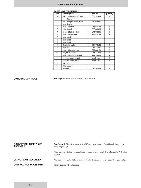
ASSEMBLY PROCEDURE<br />
PARTS LIST FOR FIGURE 7<br />
item description part no. quantity<br />
1 No. 3 splined shaft assy. S23-12474 1<br />
see figure 1<br />
No. 2 keyed shaft assy. S23-12475<br />
see figure 1<br />
2 seal retainer 033-57472 1<br />
3 shaft seal 623-00015 1<br />
4 seal retainer o-ring 671-00246 1<br />
5 hex. head screw 306-40123 4<br />
6 not used<br />
7 not used<br />
8 not used<br />
9 balance plate 033-70546 2<br />
10 spacer 033-71247 2<br />
11 soc. hd. cap screw 359-09180 2<br />
12 NyltiteÒ washer 631-45007 8<br />
13 hex. hd. washer screw 353-25018 8<br />
14 control assy. output see below 1<br />
15 control assy. input see below 1<br />
16 Not used<br />
17 Not used<br />
18 Gasket 033-91058 1<br />
OPTIONAL CONTROLS<br />
See page 64. Also, see catalog S1-2AM-7501-A.<br />
COUNTERBALANCE PLATE<br />
ASSEMBLY<br />
See figure 7. Place the two spacers (10) on the screws (11) and install through the<br />
balance plate (9).<br />
Align screws with the threaded holes in balance stem and tighten. Torque to 70 lbs-in.,<br />
6,6 Nm.<br />
SERVO PLATE ASSEMBLY<br />
CONTROL COVER ASSEMBLY<br />
Replace servo plate that was removed, refer to servo assembly page17 to servo stem.<br />
Install gaskets (18) on covers.<br />
23


