

LT3-00032-2-A - DDKS Industries, hydraulic components distributor
LT3-00032-2-A - DDKS Industries, hydraulic components distributor
LT3-00032-2-A - DDKS Industries, hydraulic components distributor

Create successful ePaper yourself
Turn your PDF publications into a flip-book with our unique Google optimized e-Paper software.
ASSEMBLY PROCEDURE<br />
HOUSING, END CAP, CAM AND<br />
BARREL ASSEMBLY<br />
See figure 6. Install new gasket (3) over the dowel pin in the mounting flange. Do not<br />
use gasket compound.<br />
Insert two socket hd. cap screws (6) through holes in balance stem (7). Attach balance<br />
stem to stroking control assembly. Torque to 70 lbs-in., 6,6 Nm.<br />
Install the housing assembly (4) over the barrel and auxiliary shaft assembly. Carefully<br />
guide the override tubes and pressure feed tubes items 2 and 4, figure 3 through the<br />
housing assembly. Position the pressure feed tubes in the slots in the housing face.<br />
NOTE: Lightly force the pressure feed tubes downward toward the stroking assembly<br />
do not bend or crimp the tubes enough so that they must be pulled up a little to snap<br />
into the housing slots. This will hold them in position for assembling the port block to<br />
the housing.<br />
Insert two hex. hd. cap screws (5) through mounting flange and into housing. Torque to<br />
100 lbs-ft., 135,6 Nm. These must be fully torqued later when main bolts are in place.<br />
Install face plate pins (1) in the holes provided in the barrel face.<br />
Apply clean heavy grease to the surface of the barrel and install the face plate (2) over<br />
the face plate pins. The surfaces must be absolutely free of scratches, dust or dirt to<br />
prevent excessive leakage. Lubricate pistons with clean system fluid through the holes<br />
in the face plate.<br />
CAUTION: The face plate has a black break-in coating on top of bronze which is bonded<br />
to a steel backing. Lightly sand the edge of the plate to identify the bronze coated<br />
side. The bronze side should go toward the port plate.<br />
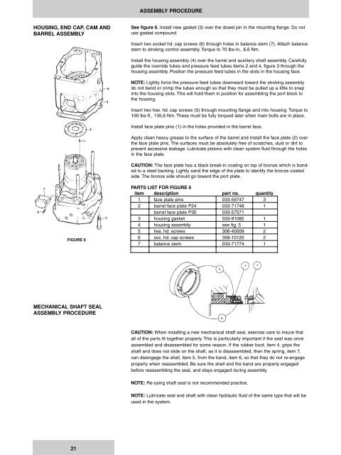
FIGURE 6<br />
PARTS LIST FOR FIGURE 6<br />
item description part no. quantity<br />
1 face plate pins 033-59747 3<br />
2 barrel face plate P24 033-71748 1<br />
barrel face plate P30 033-57571<br />
3 housing gasket 033-91082 1<br />
4 housing assembly see fig. 5 1<br />
5 hex. hd. screws 306-40009 2<br />
6 soc. hd. cap screws 358-10120 2<br />
7 balance stem 033-71774 1<br />
MECHANICAL SHAFT SEAL<br />
ASSEMBLY PROCEDURE<br />
CAUTION: When installing a new mechanical shaft seal, exercise care to insure that<br />
all of the parts fit together properly. This is particularly important if the seal was once<br />
assembled and disassembled for some reason. If the rubber boot, item 4, grips the<br />
shaft and does not slide on the shaft, as it is disassembled, then the spring, item 7,<br />
can disengage the shell, item 5, from the band, item 6, so that they do not re-engage<br />
properly when reassembled. Be sure the shell and the band are properly engaged<br />
before reassembling the seal, and stays engaged during assembly.<br />
NOTE: Re-using shaft seal is not recommended practice.<br />
NOTE: Lubricate seal and shaft with clean <strong>hydraulic</strong> fluid of the same type that will be<br />
used in the system.<br />
21


