

LT3-00032-2-A - DDKS Industries, hydraulic components distributor
LT3-00032-2-A - DDKS Industries, hydraulic components distributor
LT3-00032-2-A - DDKS Industries, hydraulic components distributor

Create successful ePaper yourself
Turn your PDF publications into a flip-book with our unique Google optimized e-Paper software.
MOUNTING FLANGE,<br />
CAM & CRADLE, BARREL &<br />
AUXILIARY SHAFT ASSEMBLY<br />
(continued)<br />
PARTS LIST FOR FIGURE 3<br />
item description part no. quantity<br />
1 barrel & aux. shaft assembly see fig.4 or 4.1 1<br />
2 override tubes item 24 see fig. 2 2<br />
3 male elbow 473-15041 2<br />
4 tube assembly P24 S13-44469 2<br />
tube assembly P30 S23-12172 2<br />
5 rocker cam & stroking assy. see fig. 2 1<br />
6 dowel pin 324-24028 2<br />
7 mounting flange 033-91137 1<br />
8 o-ring 671-00111 2<br />
9 soc. hd. cap screw 358-16260 2<br />
10 dowel pin 324-22416 1<br />
11 plug 033-57475 2<br />
12 plug 488-35061 3<br />
13 o-ring 691-00904 3<br />
Return the mounting flange to an upright position and tilt the rocker cam to either<br />
extreme attitude on the cradle.<br />
Position the barrel assembly (1) directly over the pistons. Starting with the uppermost<br />
piston, guide them one at time into the barrel bores.<br />
BARREL AND AUXILIARY<br />
DRIVE SHAFT 24 SERIES<br />
NOTE: Support the barrel on the main shaft but tilted slightly so as not to allow the<br />
barrel to drop and fully engage the barrel and shaft splines. Now the holddown assembly<br />
can be installed without any load against it.<br />
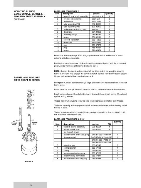
See figure 4. Install auxiliary shaft (2) large spline end first into counterbore in face of<br />
barrel spline.<br />
Install spherical seat (3) round or spherical face up into counterbore in face of barrel.<br />
Install spring retainer (4) socket side down into counterbore, install spring (5) and seat<br />
against spring retainer.<br />
Thread holddown adjusting screw (6) into counterbore approximately four threads.<br />
Tilt barrel vertically and engage main shaft spline with the barrel spline allowing barrel<br />
to drop in place.<br />
Thread holddown adjusting screw (6) into counterbore until it is flush to 0.060”, 1.52<br />
mm maximum below barrel face.<br />
FIGURE 4<br />
PARTS LIST FOR FIGURE 4 (P24)<br />
quantity<br />
item description part no. P24<br />
1 barrel & sleeve assembly S23-12091 1<br />
2 auxiliary drive shaft 033-57257 1<br />
(no through drive)<br />
auxiliary drive shaft &coupling SAE-B=S23-17444- 0 K 1<br />
(through drive) SAE-BB=S23-17448- 0 K 1<br />
SAE-C=S23-17446-0 K<br />
SAE-D=S23-17450-0 K<br />
3 spherical seat 033-57147 2<br />
4 spring retainer 033-57138 1<br />
5 spring 033-57136 1<br />
6 holddown adjusting screw 033-57139 1<br />
7 holddown adj. screw lock 033-57241 1<br />
8 holddown lock retaining ring 033-57239 1<br />
19


