Example 4 Combinational Logic â A 2 to 4 decoder with enable For ...
Example 4 Combinational Logic â A 2 to 4 decoder with enable For ...
Example 4 Combinational Logic â A 2 to 4 decoder with enable For ...

You also want an ePaper? Increase the reach of your titles
YUMPU automatically turns print PDFs into web optimized ePapers that Google loves.
<strong>Example</strong> 4<br />
<strong>Combinational</strong> <strong>Logic</strong> – A 2 <strong>to</strong> 4 <strong>decoder</strong> <strong>with</strong> <strong>enable</strong><br />
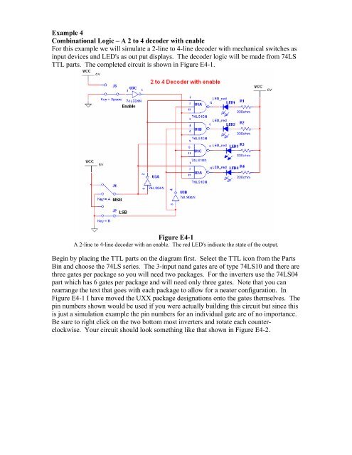
<strong>For</strong> this example we will simulate a 2-line <strong>to</strong> 4-line <strong>decoder</strong> <strong>with</strong> mechanical switches as<br />
input devices and LED's as out put displays. The <strong>decoder</strong> logic will be made from 74LS<br />
TTL parts. The completed circuit is shown in Figure E4-1.<br />
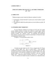
Figure E4-1<br />
A 2-line <strong>to</strong> 4-line <strong>decoder</strong> <strong>with</strong> an <strong>enable</strong>. The red LED's indicate the state of the output.<br />
Begin by placing the TTL parts on the diagram first. Select the TTL icon from the Parts<br />
Bin and choose the 74LS series. The 3-input nand gates are of type 74LS10 and there are<br />
three gates per package so you will need two packages. <strong>For</strong> the inverters use the 74LS04<br />
part which has 6 gates per package and will need only three gates. Note that you can<br />
rearrange the text that goes <strong>with</strong> each package <strong>to</strong> allow for a neater configuration. In<br />
Figure E4-1 I have moved the UXX package designations on<strong>to</strong> the gates themselves. The<br />
pin numbers shown would be used if you were actually building this circuit but since this<br />
is just a simulation example the pin numbers for an individual gate are of no importance.<br />
Be sure <strong>to</strong> right click on the two bot<strong>to</strong>m most inverters and rotate each counterclockwise.<br />
Your circuit should look something like that shown in Figure E4-2.
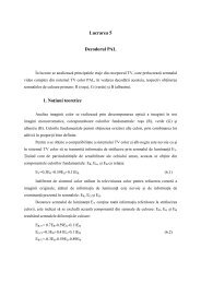
Figure E4-2<br />
Place the 3-input <strong>to</strong>gether using two packages of 74LS10 type. Use one package of<br />
74LS04 type for the inverters. Right click on the bot<strong>to</strong>m most inverters and rotate them<br />
counter-clockwise.<br />
Next we place the LED's on the board. These are on the Diodes menu in the Parts Bin.<br />
You have a choice of several colors. I have rotated the LEDs clockwise and moved their<br />
names around <strong>to</strong> tighten the configuration. After placing the first LED you can copy it<br />
and paste it for the others or you can select another LED from the in use list at the <strong>to</strong>p<br />
center of the Workbench page. Add in four 330 resis<strong>to</strong>rs as shown in Figure E4-3.<br />
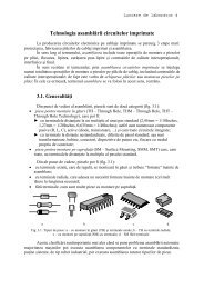
Figure E4-3<br />
Place four LEDs and four 330 resis<strong>to</strong>rs on the board as show.<br />
Finally we need <strong>to</strong> add the switches and the power supplies. Workbench has switches in<br />
two places. The switches we will use are located on the Basic menu and they are single<br />
pole double throw (SPDT) switches. (There are some momentary contact switches on the<br />
Electromechanical menu also.) Add three of the switches <strong>to</strong> the circuit and flip each<br />
horizontally as shown in Figure E4-4. Add in the digital power supply in three places for<br />
convenience.
Notice that each switch has a corresponding "key" parameter. This refers <strong>to</strong> the key on<br />
the keyboard which activates the switch during simulation. Double click on any switch<br />
and you get a menu that allows you <strong>to</strong> change this key. Change the two bot<strong>to</strong>m switches<br />
<strong>to</strong> have keys of A and B and set the <strong>to</strong>p most switch <strong>to</strong> have a key of space.<br />
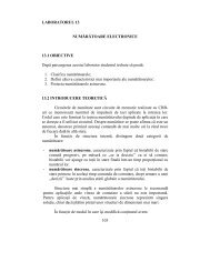
Figure E4-4<br />
The circuit <strong>with</strong> all of the components in place. Note that the key parameter of the three<br />
switches has been set <strong>to</strong> space, A, and B.<br />
Connect the wires on the circuit so that your final circuit looks like that shown in Figure<br />
E4-1. Test your completed circuit by running the simulation (push F5). If all is correct,<br />
you should be able <strong>to</strong> activate the switches by pushing the space bar, the A, or the B keys<br />
on the keyboard. To get the LEDs <strong>to</strong> light the <strong>to</strong>p switch will need <strong>to</strong> be in the ground<br />
position (active low) <strong>to</strong> <strong>enable</strong> the circuit. With the <strong>to</strong>p switch down you will be able <strong>to</strong><br />
light any LED by varying the two A and B switches <strong>to</strong> one of four different<br />
configurations.<br />
Complete the project by adding some text <strong>to</strong> your circuit. Add text by selecting<br />
PlacePlace Text from the menu. Click the cursor at the location on the screen where<br />
you want the text and enter the text by typing it in. After entering the text you can<br />
change its color by right clicking on it and selecting a color from the menu. You can also<br />
change the text font by selecting OptionsPreferencesFont and selecting a font from<br />
the menu.