Signal – Master Clock CSHU 500 Computer - Signal - NIS time
Signal – Master Clock CSHU 500 Computer - Signal - NIS time
Signal – Master Clock CSHU 500 Computer - Signal - NIS time

Create successful ePaper yourself
Turn your PDF publications into a flip-book with our unique Google optimized e-Paper software.
Elektronische Uhren- und Informations-Systeme<br />
Valterweg 10<br />
D 65817 Eppstein - Bremthal<br />
Tel.: +49 (0) 61 98 - 57 99 - 0<br />
Fax: +49 (0) 61 98 - 3 39 97<br />
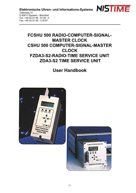
F<strong>CSHU</strong> <strong>500</strong> RADIO-COMPUTER-SIGNAL-<br />
MASTER CLOCK<br />
<strong>CSHU</strong> <strong>500</strong> COMPUTER-SIGNAL-MASTER<br />
CLOCK<br />
FZDA3-S2-RADIO-TIME SERVICE UNIT<br />
ZDA3-S2 TIME SERVICE UNIT<br />
User Handbook<br />
-1-
Elektronische Uhren- und Informations-Systeme<br />
Valterweg 10<br />
D 65817 Eppstein - Bremthal<br />
Tel.: +49 (0) 61 98 - 57 99 - 0<br />
Fax: +49 (0) 61 98 - 3 39 97<br />
F<strong>CSHU</strong> <strong>500</strong> Radio- <strong>Computer</strong> - <strong>Signal</strong> – <strong>Master</strong> <strong>Clock</strong><br />
<strong>CSHU</strong> <strong>500</strong> <strong>Computer</strong> - <strong>Signal</strong> – <strong>Master</strong> <strong>Clock</strong><br />
FZDA3-S2 Radio- Time Service Unit<br />
ZDA3-S2 Time Service Unit<br />
Operating Instructions<br />
Contents List<br />
1. General 4 -6<br />
1.1 General Description 4<br />
1.2 Operating Modes/ Inputs 4<br />
1.3 Outputs 4<br />
1.4 Processor 5<br />
1.5 Chip Card 5<br />
1.6 Technical Data 5<br />
1.7 Component Drawings 6<br />
2. Assembly and Operating Instructions 6 -13<br />
2.1 MC Assembly/ Base 6 - 7<br />
2.2 Electrical Connections /Wiring Diagram 7<br />
2.3 Aerial Assembly/Location 8<br />
2.4 Operating and Display Units 8<br />
2.5 Commissioning/Setting the Mode of Operation 9<br />
2.5.1 Start-up phase /Display after Commissioning 9<br />
2.5.2 Mode of Operation 9<br />
2.6 Main Menu – A Brief Description 9 - 11<br />
2.6.1 MC-Mode of Operation<br />
2.6.2 MC Operational Status (Radio Reception)<br />
2.6.3 Examples (radio monitoring) 11<br />
-2-<br />
Pages<br />
10<br />
10
Elektronische Uhren- und Informations-Systeme<br />
Valterweg 10<br />
D 65817 Eppstein - Bremthal<br />
Tel.: +49 (0) 61 98 - 57 99 - 0<br />
Fax: +49 (0) 61 98 - 3 39 97<br />
2.7 Code Number 12 - 13<br />
2.7.1 Activate code 12<br />
2.7.2 Input Code Number 12 - 13<br />
2.7.3 Error messages 13<br />
3. Operating Instructions/Setting the <strong>Master</strong> <strong>Clock</strong> 13 - 53<br />
3.0 Basic Initialisation of the <strong>Master</strong> <strong>Clock</strong> 13 - 14<br />
3.1 <strong>Master</strong> <strong>Clock</strong> Input and Display/ Date 14 - 16<br />
3.1.1 Error Messages 16<br />
3.2 <strong>Master</strong> <strong>Clock</strong> <strong>Signal</strong> Generator Configuration<br />
17 - 22<br />
3.2.1 Display Text Conversion 17<br />
3.2.2 Inputting the Minimum Read Time of the DCF-<strong>Signal</strong> Input 18<br />
3.2.3 Summer<strong>time</strong> (CEST) / Normal <strong>time</strong> (CET) 19 - 22<br />
3.2.4 Error messages 22<br />
3.3 Time Circuit-Configuration 23 - 28<br />
3.3.1 Circuit <strong>time</strong>/ date and Circuit Current Display 23 - 25<br />
3.3.2 Disconnect <strong>time</strong> circuits 25<br />
3.3.3 Connect <strong>time</strong> circuits 26<br />
3.3.4 Circuit <strong>time</strong> operating modes/Abbreviated Descriptions 26 - 27<br />
3.3.5 Inputting <strong>time</strong> circuit operating modes 27 - 28<br />
3.3.6 Error messages 28<br />
3.4 Time Circuits 29 - 34<br />
3.4.1 Setting <strong>time</strong> circuits/Synchronisation 29 - 30<br />
3.4.2 Error messages 30 - 31<br />
3.4.3 Monitoring circuit current 31 - 32<br />
3.4.4 Error messages 32 - 33<br />
3.4.5 Giving a single (manual) pulse/ reset 33<br />
3.4.6 Error messages 34<br />
3.5 Operating instructions / programing the clock <strong>time</strong>r 34 - 50<br />
3.5.1 Operational status of the switching outputs 34<br />
3.5.2 Switching outputs on/off manually 34 - 35<br />
3.5.3 Brief description of the switching program ` 35<br />
-3-<br />
Page
Elektronische Uhren- und Informations-Systeme<br />
Valterweg 10<br />
D 65817 Eppstein - Bremthal<br />
Tel.: +49 (0) 61 98 - 57 99 - 0<br />
Fax: +49 (0) 61 98 - 3 39 97<br />
-4-<br />
Page<br />
3.5.4 Program prioritisation 35<br />
3.5.5 Reading of Switching Time Fixtures 36 - 37<br />
a) Annual program- switching <strong>time</strong> display 36 - 37<br />
b) Weekday program- switching <strong>time</strong> display 37<br />
c) Block date switching <strong>time</strong> display 37<br />
3.5.6 Inputting of Switching Times 38 - 44<br />
a) Annual or holiday program 38 - 39<br />
b) Weekday program 39 - 41<br />
c) Block program 41 - 44<br />
3.5.7 Error messages 45 - 46<br />
3.5.8 Changing the Switching Times 46 - 49<br />
a) Annual/holiday program 46 - 47<br />
b) Weekday program 47 - 48<br />
c) Block program 48 - 50<br />
3.6. Cancel Switching Times 50 - 51<br />
a) Annual program, holiday program und weekday program 50<br />
b) Block program 50 - 51<br />
3.7 Loading the Program / Reading Switching Times from Chipcard 51 - 52<br />
3.7.1 Error messages 52<br />
3.8 Saving Programs / Switching Times on the Chip Card 52 - 53<br />
3.8.1 Error messages 53<br />
3.9 RZ Analysis Menu 54<br />
4. Addenda to the Instructions for Mondays and Commissioning 55<br />
4.1 Dimensional drawing -19„-plug-in cassette 55<br />
4.2 Electrical connections/wiring diagram 55<br />
5. Serial Interface Data Protocol 56 - 58<br />
5.1 General 56<br />
5.2 Typical <strong>time</strong> transmission 57<br />
5.3 Typical date transmission 58
Elektronische Uhren- und Informations-Systeme<br />
Valterweg 10<br />
D 65817 Eppstein - Bremthal<br />
Tel.: +49 (0) 61 98 - 57 99 - 0<br />
Fax: +49 (0) 61 98 - 3 39 97<br />
1. Generals<br />
1.1 General Description<br />
The FCSHC<strong>500</strong> Radio-<strong>Computer</strong>-<strong>Signal</strong>-<strong>Master</strong> clock <strong>Signal</strong> Generator or FZDA3-S2 radio<br />
<strong>time</strong> distribution system is a software-controlled master clock signal generator with an<br />
automatic fast configuration facility. It can control up to 3 secondary <strong>time</strong> circuits at the<br />
same <strong>time</strong> without the need for any storage battery back-up, thanks to secondary <strong>time</strong>r<br />
auto-correction. In addition, the master clock signal generator is radio-controlled via the<br />
DCF77 German <strong>time</strong> code transmitter, i.e. <strong>time</strong> and date input is fully automatic. The<br />
secondary <strong>time</strong>r reset is triggered automatically following a malfunction or mains power<br />
failure (lasting up to one week). Each <strong>time</strong> circuit has its own separately adjustable<br />
ammeter arrangement or current monitor. An external 12V or 24V power supply can also be<br />
used. A chip card on which programmed switching <strong>time</strong>s can be saved is provided for data<br />
protection purposes.<br />
Note: Some illustrations and/or texts relate directly to the <strong>CSHU</strong><strong>500</strong> / F<strong>CSHU</strong><strong>500</strong>, but do<br />
not necessarily also apply to the ZDA3-S2 / FZDA3-S2 !!<br />
1.2 Operating Modes/ Inputs<br />
The master clock signal generator has two remote control inputs for signal switching circuits<br />
such as panic circuits or signals triggered by a house or fire alarm.<br />
1.3 Outputs<br />
a) Time circuits<br />
These are three simultaneously selectable secondary <strong>time</strong> circuits: MIN –circuit, SEC -<br />
circuit and ½ minute-circuit. Circuit pulse lengths are simultaneously and freely selectable<br />
between 0.5 and 7.5.<br />
b) DCF77 – pulse diagram output<br />
This pulse diagram output is matched to the signal from the German DCF77 <strong>time</strong> signal<br />
transmitter. The DCF signal can therefore be relayed to another <strong>time</strong>r without any aerial<br />
being required. The DCF-<strong>Signal</strong> is generated by the master clock signal generator and can<br />
be output randomly to <strong>time</strong> circuits 1 to 3.<br />
c) Switch outputs<br />
The master clock has two signal circuits and holiday, annual and weekly programs can be<br />
used to schedule on/off <strong>time</strong>s or short-length pulses. Up to 325 switching <strong>time</strong>s can be<br />
input. What is more, on/off or pulse switching accurate to one second can be achieved.<br />
d) Alarm output<br />
The alarm output is designed for failure telemetry, typically, for central group interrupt, for<br />
instance.<br />
A few examples:<br />
Time diff too great : The maximum permissible reset <strong>time</strong> has been exceeded.<br />
L1 I-error (Circuit 1 current error): The current tolerance limit on the circuit has been<br />
exceeded.<br />
L1-short-circuit (circuit 1 short circuit): the electrical connections must be checked. Other<br />
messages are mentioned in the relevant chapters.<br />
e) RS 232 – data output<br />
This data output can be used to relay the <strong>time</strong> of day and date via the (RS232) serial<br />
interface to a PC or DP facility.<br />
-5-
Elektronische Uhren- und Informations-Systeme<br />
Valterweg 10<br />
D 65817 Eppstein - Bremthal<br />
Tel.: +49 (0) 61 98 - 57 99 - 0<br />
Fax: +49 (0) 61 98 - 3 39 97<br />
1.4 Processor<br />
An 80C32, used as the CPU, is the core element of the entire electronics system and is<br />
responsible for all input, output and monitoring functions.<br />
1.5 Chip card<br />
The switching <strong>time</strong>s programmed into the MC can be stored on the chip card.<br />
Technical Data:<br />
Serial I2 C Bus<br />
Memory depth 2048 Bytes<br />
ISO standard 7816<br />
Contact zone<br />
1.6 Technical data<br />
Model Number <strong>CSHU</strong><strong>500</strong><br />
ZDA3-S2<br />
F<strong>CSHU</strong><strong>500</strong><br />
FZDA3-S2<br />
Power pulse current<br />
(with integrated power supply<br />
appliance)<br />
400 mA = 66 NU at 6 mA for all 3 circuits together,<br />
Impulse current (with external <strong>500</strong> mA = 80 NU at 6 mA per circuit, total 1<strong>500</strong>mA=240 slave clocks each with<br />
power supply (option)<br />
6mA<br />
Impulse output type 1/1 or 1/ 2 minutes or 1/1 Second pulse or DCF77-telegram, pulse length<br />
adjustable from 0.5...7.5 sec.<br />
Connection of slave clocks or<br />
other <strong>time</strong> receivers<br />
Via connection terminals (in the plug-in base)<br />
Supply voltage<br />
230V ±10% / max. 15VA 12V = 600 mA<br />
power consumption,<br />
current consumption<br />
24V = 600 mA<br />
(at full load)<br />
Accumulator or data<br />
Running accuracy without radio<br />
approx. 10 years<br />
control<br />
0(C...+40(C ± 5 × 10⁻⁶ at +17°C...+23°C equivalent to approx. 0,4s / day<br />
operating temperature range 0°C...+50°C *<br />
0°C...+40°C with integrated power supply<br />
condensation not permissible<br />
Housing/ protection rating High impact –resistant polystyrene, Aluminium plug-in rack for<br />
Colour: light grey/Connecting base 19“-mounting rack / IP30 protection<br />
umber-grey / surface- or standard 35<br />
mm rack-mounted, IP40 protection<br />
(without mounting)<br />
Dimensions of housing<br />
(W×H×D / mm)<br />
75×158×120 (with socket) 121,5x129x170 (3 HE, 24 TE)<br />
Weight approx. 980 g approx. 1200 g<br />
Data output RS232 PC-interface: <strong>time</strong> of day, date, day of the week, baud rate: 4800<br />
Remote control for signal<br />
circuits<br />
Panic circuit, signal trip via house alarm or fire alarm<br />
Alarm output Open collector; 30V / 0,5A<br />
Switch outputs/<br />
Max. Make-/permanent-/Break current 4A/3A/2A; max. make-break capacity range:<br />
<strong>Signal</strong> outputs K1 and K2 60W (125VA) Switching voltage range: 0,1V - 250V; ON-OFF and pulse function,<br />
week-day, holiday, annual and block program; Up to 325 switching <strong>time</strong>s, onesecond<br />
switching <strong>time</strong> interval OPTION: Switching <strong>time</strong>s can also be saved on the<br />
chip card<br />
OPTION:<br />
Housing: polycarbonate with 10 m connecting cable/IP65 / Dimensions :110x80x65<br />
Radio receiver (projecting) mm /180° swivel<br />
Weight of radio receiver approx. <strong>500</strong> g incl. swivel arm and 10 m of cable<br />
* In the case of 240 secondary <strong>time</strong>rs = Full load and external supply<br />
-6-
Elektronische Uhren- und Informations-Systeme<br />
Valterweg 10<br />
D 65817 Eppstein - Bremthal<br />
Tel.: +49 (0) 61 98 - 57 99 - 0<br />
Fax: +49 (0) 61 98 - 3 39 97<br />
Note: Ensure spark suppression via contact assembly is provided by the customer!<br />
-7-
Elektronische Uhren- und Informations-Systeme<br />
Valterweg 10<br />
D 65817 Eppstein - Bremthal<br />
Tel.: +49 (0) 61 98 - 57 99 - 0<br />
Fax: +49 (0) 61 98 - 3 39 97<br />
1.7 Component Drawing<br />
Resting of plug-in jumpers for a 12V to 24V service voltage<br />
62<br />
1<br />
72<br />
2<br />
82<br />
3<br />
92<br />
4<br />
03<br />
5<br />
13<br />
6<br />
23<br />
7<br />
33<br />
8<br />
43<br />
9<br />
3<br />
2<br />
1<br />
3<br />
2<br />
1<br />
3<br />
2<br />
1<br />
3<br />
2<br />
1<br />
53<br />
01<br />
J6<br />
J5<br />
J4<br />
J3<br />
63<br />
11<br />
3<br />
2 J8<br />
1<br />
73<br />
21<br />
oben 12V<br />
unten 24V<br />
2. Assembly and Operating instructions<br />
83<br />
31<br />
-8-<br />
93<br />
41<br />
04<br />
51<br />
14<br />
61<br />
(2 und 3)<br />
Es müssen alle Steckbrücken<br />
umgestellt werden !<br />
(1 und 2)<br />
The following points 2.1 (MC Assembly / Base) and 2.2 (Electrical connections /<br />
wiring diagram) refer to master clock signal generators <strong>CSHU</strong><strong>500</strong> and F<strong>CSHU</strong><strong>500</strong>.<br />
The corresponding drawings for the 19„ plug-in cassettes ZDA3-S2 or FZDA3-S2 appear in<br />
point 4 (on page 55).<br />
2.1 MC Assembly/Base<br />
Remove the master clock signal generator from the connecting base. The master clock<br />
signal generator base is mounted with two screws, using any 230V mains connecting cable<br />
(or cable for external DC supply and taking account of any slave, DCF77- receivers, and so<br />
on, on the wall or on the standard rack so that the terminal strip is located on the RHS.<br />
Advice on Installation<br />
The highly integrated electronics are protected to the hilt against the effects of faults.<br />
However, in the event of exceptionally high interference, the possibility that the electronics<br />
may be affected cannot be ruled out. In order to minimise faults, avoid the following<br />
circumstances during installation:<br />
1. Do not mount the master clock signal generator immediately next to interference<br />
transmitters such as power contractors, circuits carrying high current, solenoid valves,<br />
thyristor controls, etc.<br />
2. 2. Directly operated inductive consumers should be suppressed with suitable<br />
interference dissipaters such as varsities, RC-units, etc.<br />
3. Inductive and capacitive consumers will impose an extremely heavy load on the channel<br />
output relay assemblies. Check whether isolating relays or contractors need to be<br />
installed.<br />
24<br />
71<br />
34<br />
81<br />
44<br />
91<br />
54<br />
02<br />
64<br />
12<br />
74<br />
22<br />
84<br />
32<br />
94<br />
42<br />
05<br />
52<br />
B<br />
L
Elektronische Uhren- und Informations-Systeme<br />
Valterweg 10<br />
D 65817 Eppstein - Bremthal<br />
Tel.: +49 (0) 61 98 - 57 99 - 0<br />
Fax: +49 (0) 61 98 - 3 39 97<br />
Dimensions of casing :<br />
2.2 Electrical connections / connection wiring<br />
-9-
Elektronische Uhren- und Informations-Systeme<br />
Valterweg 10<br />
D 65817 Eppstein - Bremthal<br />
Tel.: +49 (0) 61 98 - 57 99 - 0<br />
Fax: +49 (0) 61 98 - 3 39 97<br />
-10-
Elektronische Uhren- und Informations-Systeme<br />
Valterweg 10<br />
D 65817 Eppstein - Bremthal<br />
Tel.: +49 (0) 61 98 - 57 99 - 0<br />
Fax: +49 (0) 61 98 - 3 39 97<br />
2.3 Mounting / Aerial Location<br />
A suitable location must be found for the aerial (plus receiver). Install the aerial possibly<br />
close to the window or out-of-doors.<br />
In order to establish the optimal direction for reception, first of all open the aerial cover to<br />
disclose the red LED (optical monitoring receiver) on the printed circuit board. This LED can<br />
now be used for checking reception. The aerial is rotated slowly until the LED flashes at<br />
precisely 1-sec. intervals (There should be no flickering of the LED; illumination <strong>time</strong>: 0.1 or<br />
0.2 seconds, except for Sec. No. 59).<br />
After approx. 4……5 minutes of good reception, the display shows the official <strong>time</strong> of day<br />
(and the date) for Germany. If this is not the case, possibly an alternative aerial location<br />
should be sought. Do not move or turn the aerial during the read-in phase!<br />
Fit the aerial casing horizontally:<br />
2.4 Operation and display units<br />
LCD - display<br />
One step back<br />
scroll up<br />
Cursors go to the Scroll down<br />
Down<br />
Left or right<br />
Clear or 2nd function<br />
Made in Germany<br />
HUF 20:19:59<br />
AHI // MW<br />
Return Select Enter<br />
Zurück Auswahl Eingabe<br />
Up<br />
Left Right<br />
Funktion<br />
Löschen<br />
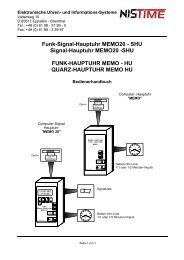
Funk-<strong>Computer</strong>-<br />
<strong>Signal</strong>-Hauptuhr<br />
F<strong>CSHU</strong> <strong>500</strong><br />
Radio-<strong>Computer</strong>-<strong>Signal</strong> <strong>Master</strong> <strong>Clock</strong> F<strong>CSHU</strong> <strong>500</strong><br />
-11-<br />
Shift<br />
Clear
Elektronische Uhren- und Informations-Systeme<br />
Valterweg 10<br />
D 65817 Eppstein - Bremthal<br />
Tel.: +49 (0) 61 98 - 57 99 - 0<br />
Fax: +49 (0) 61 98 - 3 39 97<br />
2.5 Commissioning/ Setting the Mode of Operation<br />
Note: On delivery, the master clock signal generator is in basic initialisation status<br />
(See page 13)!<br />
2.5.1 Start-up Phase/ Display after starting<br />
The master clock signal generator becomes operational on connection to the 230V mains.<br />
It then enters the start-up phase and the following LCD display appears on the start-up<br />
phase window.<br />
MCW 20:19:59<br />
Start-up Phase Window:<br />
At start-up, the aerial should be checked to see whether it is or is not connected and DCF<br />
operation or quartz operation selected accordingly. This window can be by-passed by<br />
activating the ‚ SELECT‘ key. The Main Menu then appears.<br />
Note: During the start-up phase, the aerial may not be moved otherwise interferencefree<br />
radio reception cannot be guaranteed!<br />
2.5.2 Mode of Operation<br />
a) DCF-Operation<br />
If a good DCF signal is being received, after approx. 3 to 5 minutes the master clock<br />
switches to the Main Menu. The MCSGR-code ((MCSGR in German) stands for master<br />
clock signal generator-radio). If radio reception is poor, the read-in procedure is interrupted<br />
and the master clock signal generator is started by means of the emergency clock<br />
incorporated. The MCSGQ (MCSGQ in German) code then appears in the Main Menu<br />
(MCSGQ stands for master clock signal generator-quartz). In this case, the position of the<br />
aerial should be checked and may need to be changed.<br />
b) Quartz-Operation<br />
If no DCF signal is received, then 30 seconds later the master clock signal generator<br />
automatically switches to quartz operation. The MCSGQ (MCSGQ) code appears in the<br />
Main Menu (MCSGQ stands for master clock signal generator-quartz).<br />
c) Satellite-Operation<br />
The master clock signal generator is also designed for satellite reception via GPS (Global-<br />
Position-System). There is therefore scope for receiving a signal from different satellites via<br />
an optional GPS converter; the signal is then output as a DCF signal. This feature is<br />
intended particularly for those countries located out of the range of the DCF signal.<br />
2.6 Main menu - A Brief Description<br />
MCW 20:19:59<br />
Start-up phase<br />
Once the start-up menu has been completed, the master clock signal generator<br />
automatically returns to the Main Menu which contains information about master clock<br />
mode of operation, <strong>time</strong> of day, date, operational status of <strong>time</strong> circuits 1 – 3 and switch<br />
outputs 1 – 2. From this point onwards, the ‚SELECT‘ key is accessed from the SELECT<br />
Menu.<br />
From here, configurations, switching <strong>time</strong> programs, correction programs and data security<br />
can be called up and/or programmed.<br />
-12-
Elektronische Uhren- und Informations-Systeme<br />
Valterweg 10<br />
D 65817 Eppstein - Bremthal<br />
Tel.: +49 (0) 61 98 - 57 99 - 0<br />
Fax: +49 (0) 61 98 - 3 39 97<br />
Main mane window :<br />
<strong>Master</strong> clock mode of operation Time (hour, min. sec)<br />
Code<br />
Operational status <strong>time</strong> circuit 1 Timer circuit code/<br />
Switch output code<br />
Operational status <strong>time</strong> circuit 2 Switch output 2<br />
Operational status <strong>time</strong> circuit 3 switch output 1<br />
2.6.1 <strong>Master</strong> clock signal generator – mode of operation<br />
There are two possible codes for MC mode of operation, namely:<br />
a) MCSGR (MCSGR in German) (<strong>Master</strong> clock signal generator-radio)<br />
signifies radio synchronically to the DCF signal<br />
b) MCSGQ (MCSGQ in German)(<strong>Master</strong> clock signal generator-Quartz)<br />
denotes quartz synchronically to an internal <strong>time</strong> datum<br />
To display the date, keep the ‚RETURN‘ key depressed.<br />
The date will now be displayed in the second row of the Main Menu:<br />
Main Menu-Window/Date :<br />
Menu.<br />
date (day, month, year)<br />
weekday<br />
If the ´RETURN´ key is released once more, the system automatically returns to the Main<br />
2.6.2 MC Operational status (radio reception)<br />
MCSGR20:19:59<br />
AHI // MW<br />
MCSGR20:19:59<br />
MO 30.12.94<br />
DCF-reception is monitored constantly and can be interrogated from the Main Menu via the<br />
‚SHIFT‘ and ‚LEFT‘ keys.<br />
The following symbols appear in the Main Menu window:<br />
F+ denotes : Radio, good DCF-<strong>Signal</strong><br />
F- denotes : Radio, poor DCF-<strong>Signal</strong><br />
- - denotes : no radio, no serviceable DCF-<strong>Signal</strong> received (Quartz clock operation)<br />
-13-
Elektronische Uhren- und Informations-Systeme<br />
Valterweg 10<br />
D 65817 Eppstein - Bremthal<br />
Tel.: +49 (0) 61 98 - 57 99 - 0<br />
Fax: +49 (0) 61 98 - 3 39 97<br />
The ´SHIFT´ and ´RIGHT´ keys can be used to Return to the Main Menu.<br />
2.6.3 Examples (Radio monitoring)<br />
Main Menu Window:<br />
MC- mode of operation : F = Funk (Radio), DCF-operation<br />
MC –<strong>time</strong> of day : 20 hrs., 19 min., 59 Sec.<br />
<strong>time</strong> circuit 1 : A = Automatic <strong>time</strong> comparison mode (<strong>time</strong> circuit /<br />
<strong>Master</strong> clock signal<br />
Generator)<br />
<strong>time</strong> circuit 2 : H = Halt (disconnected)<br />
<strong>time</strong> circuit 3 : ( = Inactive<br />
Switching output K1 : / = Switching output K1 off<br />
Switching output K2 : I = Switching output K2 on<br />
<strong>time</strong> circuit code 1 : MW = Minute circuit with summer<strong>time</strong> reset<br />
Main menu Window:<br />
After ´SHIFT´ and ´LEFT´ key actuation, the following window appears:<br />
MC-mode of operation : F = Funk (Radio), DCF-operation<br />
Time of day : 20 hrs, 19 min, 59 Sec<br />
<strong>time</strong> circuit 1 : A = Automatic <strong>time</strong> comparison mode (<strong>time</strong> circuit /<br />
<strong>Master</strong> clock signal<br />
Generator)<br />
<strong>time</strong> circuit 2 : H = Halt (Off)<br />
<strong>time</strong> circuit 3 : I = Inactive<br />
Switching output K1 : / = Switching output K1 off<br />
Switching output K2 : / = Switching output K2 off<br />
MCSGR20:19:59<br />
AHI /| MW<br />
MCSGR 20:19:59<br />
AHI // F+<br />
Radio monitoring : F+ = Radio reception, good DCF-<strong>Signal</strong><br />
-14-
Elektronische Uhren- und Informations-Systeme<br />
Valterweg 10<br />
D 65817 Eppstein - Bremthal<br />
Tel.: +49 (0) 61 98 - 57 99 - 0<br />
Fax: +49 (0) 61 98 - 3 39 97<br />
After ´SHIFT´ and ´RIGHT´ key actuation, return to Main Menu.<br />
2.7 Code number<br />
The configurations and switching <strong>time</strong> programs for the master clock signal generator can<br />
be protected against unauthorised access by means of a code number. In the standard<br />
configuration, this code is not activated, i.e. changes can be made.<br />
2.7.1 Code activation<br />
If the code has been activated and an input or change is attempted, the: ´Invalid Code<br />
Number´ message appears. With the active code, reading of switching <strong>time</strong>s or circuit<br />
interrogation is feasible.<br />
Example: Activate Code (access protection active) :<br />
Step Key LCD display Note<br />
1 ´SHIFT´ and ´SELECT´ Code-Window<br />
2 ´ENTER´ Code activated<br />
3 ´CLEAR´ Return to Main Menu<br />
The code number must be input into the Main Menu before the next input or attempt at<br />
change otherwise ´Code number invalid‘‘ will be displayed.<br />
2.7.2 Code number Input<br />
If the Code number is activated and data are then input or amended, these actions must be<br />
preceded by entry of a code number!<br />
For example: Code number Input (Access protection removed) :<br />
Step Key LCD display Note<br />
1 ´SHIFT´ and ´SELECT´ Code input<br />
2 ´UP´ or ´DOWN´ Select number<br />
Step Key LCD display Note<br />
3 ´LEFT´ or ´RIGHT´ Select location<br />
Code-number<br />
reset ?<br />
Code-number<br />
invalid<br />
MCSGR20:19:59<br />
AAA // MW<br />
Code-number<br />
select 0000<br />
Code-number<br />
select 9000<br />
Code-number<br />
select 9071<br />
-15-
Elektronische Uhren- und Informations-Systeme<br />
Valterweg 10<br />
D 65817 Eppstein - Bremthal<br />
Tel.: +49 (0) 61 98 - 57 99 - 0<br />
Fax: +49 (0) 61 98 - 3 39 97<br />
(Repeat Steps 2 and 3 until the correct Code 9071 has been input)<br />
4 ´ENTER´ Code-input and reversion to Main menu<br />
2.7.3 Error message - Code -<br />
If the ´Code number invalid´ message appears, then the code is activated and inputs are<br />
barred or the wrong number has been selected during code input.<br />
Tip: ´CLEAR´ can be used to erase the message. Now the code can either be input<br />
correctly or deactivated.<br />
3. Operating Instructions/ Setting up the master clock signal generator<br />
The master clock signal generator is programmed exclusively via the key field. The<br />
´SELECT´ is used to access the Selection Menu where the ´UP´ or ´DOWN´ keys are<br />
used to browse the sub-menus.<br />
3.0 Basic Initialisation of the <strong>Master</strong> <strong>Clock</strong> <strong>Signal</strong> Generator<br />
Or ‚How to initialise the MC‘ i.e., how to Return to Basic Operational Status. The following<br />
configuration is then set up.<br />
* DCF – Minimum read-in <strong>time</strong>: 3 Minutes<br />
* Displayed text: German<br />
* The <strong>time</strong> of the master clock signal generator is reset to 00:00:00 <strong>time</strong> and the date to 01.01.94.<br />
* Circuit outputs 1 – 3 are in halt status.<br />
* All <strong>time</strong> circuits are set as minute circuits of 2 second pulse duration and for changeover<br />
from CET to CEST. Circuit current monitoring is deactivated, i.e., the reference current (V)<br />
and the current tolerance (D) register 0 % of<br />
* CET / CEST – <strong>time</strong>s are cancelled<br />
* All switching <strong>time</strong>s are cancelled<br />
* All switching outputs are disconnected<br />
* RZ-analysis Menu – Counter readings cancelled.<br />
WARNING !! WARNING !! WARNING !! WARNING !! WARNING<br />
!!<br />
Initialisation puts the MC in the configuration described above. Any <strong>time</strong>s stored or<br />
programmed will be lost and will have to be input. A security interrogation precedes<br />
initialisation and provides an opportunity, via use of the `RETURN´ key, to return to the<br />
selection menu without initialisation.<br />
Example: MC Initialisation :<br />
MCSGR20:19:59<br />
AAA // MW<br />
-16-
Elektronische Uhren- und Informations-Systeme<br />
Valterweg 10<br />
D 65817 Eppstein - Bremthal<br />
Tel.: +49 (0) 61 98 - 57 99 - 0<br />
Fax: +49 (0) 61 98 - 3 39 97<br />
Step Key LCD display Note<br />
1 1x ´SELECT´ Selection Menu<br />
2 2x ´DOWN´<br />
Initialisation window<br />
3 1x ´ENTER´<br />
Security interring. window<br />
4 1x ´ENTER´ <strong>Master</strong> clock signal gen. is initialised<br />
5 Return to Init-Window<br />
6 ´RETURN´ Return to Main Menu<br />
3.1 <strong>Master</strong> clock signal generator <strong>time</strong>/ -date input and display (to DCF operation)<br />
In quartz operation, both <strong>time</strong> and date can be input manually. In DCF operation, on the other hand,<br />
manual setting of <strong>time</strong> and date is impossible because the reading in of <strong>time</strong> and date is done via<br />
the DCF signal. In this case the following message appears on the display:<br />
To cancel this message, the ‚CLEAR‘ key is activated. To set the <strong>time</strong> and date of the<br />
master clock signal generator the three <strong>time</strong> circuits must first of all be disconnected!<br />
The master clock signal generator <strong>time</strong> is displayed in the upper row of the window. To<br />
arrange for the date to be displayed in the second row, the ´RETURN´ key must be kept<br />
depressed.<br />
For example: Setting the <strong>time</strong> and date.<br />
Step Key LCD display Note<br />
DCF-clock<br />
No setting<br />
MCSGR20:19:59<br />
Annual Pr.<br />
MCSGR20:19:59<br />
Initial.<br />
Yes =Enter<br />
No =Return<br />
MCSGR20:19:59<br />
Init running<br />
MCSGR00:00:00<br />
Initial.<br />
MCSGR00:00:00<br />
HHH // MW<br />
-17-
Elektronische Uhren- und Informations-Systeme<br />
Valterweg 10<br />
D 65817 Eppstein - Bremthal<br />
Tel.: +49 (0) 61 98 - 57 99 - 0<br />
Fax: +49 (0) 61 98 - 3 39 97<br />
1 Switch off <strong>time</strong> circuits 1-3 (see 3.3.2 - Page 25)<br />
2 1x ´SELECT´ Selection Menu<br />
3 5x ´DOWN´ <strong>Clock</strong> regulation<br />
4 1x ´ENTER´ Time /Date<br />
5 1x ´ENTER´ Input mode<br />
6 ´UP´ or ´DOWN´ Change number<br />
7 ´LEFT´ or ´RIGHT´ Shift cursor to hr, min, sec,month,<br />
year<br />
Repeat Steps 6 and 7, until the desired <strong>time</strong> and date have been input. (The day of the week is<br />
calculated by the master clock signal generator ).<br />
Start MC<br />
1x´ENTER´<br />
9 2x ´RETURN´ Return to the Main Menu<br />
10 Reconnect <strong>time</strong> circuits 1-3 (See 3.3 - Page 26)<br />
Advice re: Step 8 :<br />
MCSGQ19:19:59<br />
Annual Pr.<br />
MCSGQ19:19:59<br />
Set <strong>Clock</strong><br />
MCSGQ19:19:59<br />
MON 30.12.94<br />
MCSGQ19:19:59<br />
MON 30.12.94<br />
MCSGQ20:19:59<br />
MON 30.12.94<br />
MCSGQ20:19:59<br />
MON 30.12.94<br />
MCSGQ20:19:00<br />
MON 30.12.94<br />
MCSGQ20:19:00<br />
HHH // MW<br />
If the second display is showing between 0 and 29, the <strong>time</strong> has still not been readjusted<br />
manually. Once the ´ENTER‘ key has been activated, the master clock signal generator<br />
starts registering the seconds from 0. The minute reading remains unaffected. However if<br />
the <strong>time</strong> is between 30 and 59 and the MC is already going, the minute reading is raised by<br />
one minute.<br />
-18-
Elektronische Uhren- und Informations-Systeme<br />
Valterweg 10<br />
D 65817 Eppstein - Bremthal<br />
Tel.: +49 (0) 61 98 - 57 99 - 0<br />
Fax: +49 (0) 61 98 - 3 39 97<br />
3.1.1 Error messages<br />
If the following message appears at Step 4 then at least 1 <strong>time</strong>r is in auto <strong>time</strong> comparison mode<br />
Tip: Using the ´CLEAR´ key, cancel the error message.<br />
Return to the Main Menu using the ´RETURN´ key .<br />
Switch off <strong>time</strong> circuits with the ´SHIFT´ and ´DOWN´ keys (See 3.3.2 - Page 25)<br />
Start all over again with the <strong>time</strong>/date (Step 2)<br />
If the <strong>time</strong> circuits or switching outputs are receiving no pulses and/or the slave clickers are<br />
not calibrating, then the <strong>time</strong> circuits have failed to come on again.<br />
Tip: In the Main Menu, using the ´SHIFT´ and ´UP´ keys, reconnect the <strong>time</strong> circuits.<br />
If the message ´Code number invalid´ appears, then unauthorised access countercode<br />
has been activated.<br />
Tip : The message can be cancelled using ´CLEAR´. The code can now be input (See<br />
2.7.2 - Pages 12-13).<br />
3.2 <strong>Master</strong> clock <strong>Signal</strong> Generator Configuration<br />
3.2.1 Display Text Conversion<br />
The master clock signal generator display can operate in two languages (German and English).<br />
Example : German to English display text conversion:<br />
Step Key LCD display Note<br />
1 Disconnect <strong>time</strong> circuits 1-3 (See 3.3.2 - Page 25)<br />
2 1 x ´SELECT´ Selection menus<br />
Circuit still<br />
in auto<br />
MCSGQ20:19:59<br />
Annual pro.<br />
-19-
Elektronische Uhren- und Informations-Systeme<br />
Valterweg 10<br />
D 65817 Eppstein - Bremthal<br />
Tel.: +49 (0) 61 98 - 57 99 - 0<br />
Fax: +49 (0) 61 98 - 3 39 97<br />
3 7x ´UP´ or 6 x ´DOWN´ Time configurations<br />
4 1x ´ENTER´ Text-Window<br />
5 1x ´ENTER´ Input mode<br />
6 ´UP´ or ´DOWN´ Language selections<br />
7 1x ´ENTER´ Input Close<br />
8 2x ´RETURN´ Return to Main Menu<br />
9 Connect <strong>time</strong> circuits 1-3 (See 3.3.3 - Page 26)<br />
3.2.2 Entry of Minimum DCF-<strong>Signal</strong> Read-in Time (In DCF-operation only)<br />
In this instance, the master clock signal generator specifies the minimum <strong>time</strong> for DCF<br />
signal read-in. The read-in <strong>time</strong> is adjustable to either 3 or 5 minutes. If the DCF signal has<br />
not been read successfully by this <strong>time</strong>, the master clock signal generator automatically<br />
makes a fresh attempt.<br />
Example: DCF – <strong>Signal</strong> Minimum Read-in Time :<br />
Step Key LCD display Note<br />
1 Disconnect <strong>time</strong> circuits 1-3 (See 3.3.2 - Page 25)<br />
2 1 x ´SELECT´ selection menus<br />
MCSGQ20:19:59<br />
<strong>Clock</strong> Conf.<br />
MCSGQ20:19:59<br />
Text deut<br />
MCSGQ20:19:59<br />
Text deut<br />
MCSGQ20:19:59<br />
Text engl<br />
MCSGQ20:19:59<br />
Text engl<br />
MCSGQ20:19:59<br />
HHH //<br />
MCSGR19:19:59<br />
Annual Pr.<br />
-20-
Elektronische Uhren- und Informations-Systeme<br />
Valterweg 10<br />
D 65817 Eppstein - Bremthal<br />
Tel.: +49 (0) 61 98 - 57 99 - 0<br />
Fax: +49 (0) 61 98 - 3 39 97<br />
3 7x ´UP´ or 6x ´DOWN´ Time Configuration Menu<br />
4 1x ´ENTER´ Text Window<br />
5 1x ´UP´ or 4x ´DOWN´ Min. read <strong>time</strong> window<br />
6 1x ´ENTER´ Readiness for input<br />
7 ´UP´ or ´DOWN´ 3 or 5 minute selection<br />
8 1x ´ENTER´ Store input<br />
9 2x ´RETURN´ Return to Main Menu<br />
10 Connect <strong>time</strong> circuits 1-3 (See 3.3.3 - Page 26)<br />
MCSGR19:19:59<br />
Time-config.<br />
MCSGR19:19:59<br />
Text German<br />
MCSGR20:19:59<br />
DCFoK 3 min<br />
MCSGR19:19:59<br />
DCFoK 3 min<br />
MCSGR20:19:59<br />
DCFoK 5 min<br />
MCSGR19:19:59<br />
DCFoK 5 min<br />
MCSGR20:19:59<br />
HHH //<br />
3.2.3 Summer <strong>time</strong> (CEST = Central European Summer Time) / Normal <strong>time</strong> (CET<br />
= Central European Time)<br />
CET to CEST conversion and vice-versa is adjusted automatically by the MC in DCF<br />
operation. At the changeover point from (CET) to (CEST), the master clock signal generator<br />
display, immediately after receiving the new valid <strong>time</strong>, automatically moves the <strong>time</strong><br />
forward by an hour. The slave clickers receive additional pulses in the abbreviated<br />
switching rhythm. Conversely, during the CEST to CET changeover, the slave clickers are<br />
delayed by an hour. The <strong>time</strong> changes for the slave clickers even occur despite reception<br />
problems, for example, (variously according to whether Sept. or Oct.-configured). CET is<br />
also known as normal <strong>time</strong> (winter <strong>time</strong>).<br />
Manual configuration is possible with the following Input:<br />
a) Sept : Changeover from CET to CEST during the last weekend in March<br />
-21-
Elektronische Uhren- und Informations-Systeme<br />
Valterweg 10<br />
D 65817 Eppstein - Bremthal<br />
Tel.: +49 (0) 61 98 - 57 99 - 0<br />
Fax: +49 (0) 61 98 - 3 39 97<br />
Changeover from CEST to CET during the last weekend in September<br />
b) Oct : Changeover from CET to CEST during the last weekend in March<br />
Changeover from CEST to CET during the last weekend in October<br />
The conversion takes place on the Sunday of the last weekend.<br />
c) Date : Changeover from CET to CEST and from CEST to CET is effected via separate<br />
date inputs (CET / CEST)<br />
DCF operation needs no date input as the changeover is radio-prompted.<br />
d) Aerial: CET / CEST changeover via the aerial signal is conditional upon clear reception<br />
of the new date, i.e., provided radio reception is interference-free at the<br />
moment of conversion.<br />
(true of both DCF signal and GPS signal)<br />
The MC also has facilities that also allow manual CET / CEST <strong>time</strong> conversion in quartz<br />
operation. This is carried out with the 3 <strong>time</strong> circuits off (See 3.3.2 - Page 25). The<br />
procedure is as follows:<br />
Example: Change summer <strong>time</strong> end from September to October:<br />
Step Key LCD display Note<br />
1 Disconnect <strong>time</strong> circuits 1-3 (See 3.3.2 - Page 25)<br />
2 1x ´SELECT´ Selection Menu<br />
3 7x ´UP´ or 6x ´DOWN´ Time config. Menu<br />
Step Key LCD display Note<br />
MCSGQ20:19:59<br />
Annual Pro.<br />
MCSGQ20:19:59<br />
<strong>Clock</strong> conf.<br />
MCSGQ20:19:59<br />
Text deut<br />
4 1x ´ENTER´ Time Config. - Window<br />
MCSGQ20:19:59<br />
SZ/WZ SEP<br />
5 2x ´UP´ or 3x ´DOWN´ ST / WT- Window<br />
-22-
Elektronische Uhren- und Informations-Systeme<br />
Valterweg 10<br />
D 65817 Eppstein - Bremthal<br />
Tel.: +49 (0) 61 98 - 57 99 - 0<br />
Fax: +49 (0) 61 98 - 3 39 97<br />
6 1x ´ENTER´ Input-Mode<br />
7 ´UP´ or ´DOWN´ ST / WT-Configuration<br />
8 1x ´ENTER´ Store Input<br />
9 2x ´RETURN´ Return to Main Menu<br />
10 Connect <strong>time</strong> circuits 1-3 (See 3.3.3 - Page 26)<br />
Date selection involves the following steps:<br />
Example: The changeover from CET to CEST takes place on 30.03., and changeover from<br />
CEST to CET on 01.11. :<br />
Step Key LCD display Note<br />
1 Disconnect <strong>time</strong> circuits 1-3 (See 3.3.2 - Page 25)<br />
2 1 x ´SELECT´ Selection menus<br />
3 7x ´UP´ or 6x ´DOWN´ Time config. - Menu<br />
Step Key LCD display Note<br />
4 1x ´ENTER´ Tim config. Window<br />
MCSGQ20:19:59<br />
SZ/WZ SEP<br />
MCSGQ20:19:59<br />
SZ/WZ Oct<br />
MCSGQ20:19:59<br />
SZ/WZ Oct<br />
MCSGQ20:19:59<br />
HHH // MW<br />
MCSGQ20:19:59<br />
Annual Pro.<br />
MCSGQ20:19:59<br />
<strong>Clock</strong> conf.<br />
MCSGQ20:19:59<br />
Text deut<br />
-23-
Elektronische Uhren- und Informations-Systeme<br />
Valterweg 10<br />
D 65817 Eppstein - Bremthal<br />
Tel.: +49 (0) 61 98 - 57 99 - 0<br />
Fax: +49 (0) 61 98 - 3 39 97<br />
5 2x ´UP´ or 3x ´DOWN´ ST / WT- Window<br />
6 1x ´ENTER´ Input-Modus<br />
7 1x ´UP´ Date Window<br />
8 1x ´UP´ CEST-window<br />
9 1x ´ENTER´ Input mode<br />
10 ´UP´ or ´DOWN´ Date select<br />
11 1x ´ENTER´ Store<br />
12 1x ´UP´ CET-Window<br />
13 1x ´ENTER´ Input mode<br />
14 ´LEFT´ or ´RIGHT´ Move cursor<br />
MCSGQ20:19:59<br />
SZ/WZ SEP<br />
MCSGQ20:19:59<br />
SZ/WZ SEP<br />
MCSGQ20:19:59<br />
SZ/WZ Date<br />
MCSGQ20:19:59<br />
MESZ 01.01.<br />
MCSGQ20:19:59<br />
MESZ 01.01.<br />
MCSGQ20:19:59<br />
MESZ 30.03.<br />
MCSGQ20:19:59<br />
MESZ 30.03.<br />
MCSGQ20:19:59<br />
MEZ 01.01.<br />
MCSGQ20:19:59<br />
MEZ 01.01.<br />
MCSGQ20:19:59<br />
MEZ 01.01.<br />
-24-
Elektronische Uhren- und Informations-Systeme<br />
Valterweg 10<br />
D 65817 Eppstein - Bremthal<br />
Tel.: +49 (0) 61 98 - 57 99 - 0<br />
Fax: +49 (0) 61 98 - 3 39 97<br />
Step0 Key LCD-Display Note<br />
15 ´UP´ or ´DOWN´ Select date<br />
16 1x ´ENTER´ input store<br />
17 2x ´RETURN´ Return to main menu<br />
18 Connect <strong>time</strong> circuits 1-3 (see 3.3.3 - page 26)<br />
Date configuration has top priority, i.e., in DCF operation or GPS operation, the MC<br />
automatically switches over to quartz operation! If CEST and CET are dated for the same<br />
day, date selection will be deactivated automatically and the MC will operate in CET! Also<br />
note that at least one month must elapse between the CET and CEST changeover date.<br />
Possible entry: e.g 31.03 (CEST) and 01.04 (CET).<br />
3.2.4 Error Message<br />
MCSGQ20:19:59<br />
MEZ 01.11.<br />
MCSGQ20:19:59<br />
MEZ 01.11.<br />
MCSGQ20:19:59<br />
HHH // MW<br />
If the display shows ‚S/W date wrong‘, this means that the requisite one month gap has not<br />
been left between the CET and CEST date.<br />
Tip : Activate ´CLEAR´ key (cancel Error message) and change date.<br />
Tip : If the display shows ´Circuit still in Auto ´, this means that at least one <strong>time</strong>r is still in<br />
service. Activate ´CLEAR´ key (cancel Error message) and return to the Main<br />
Menu. Once there, set all <strong>time</strong> circuits to OFF using the ´SHIFT´ and ´DOWN´<br />
keys.<br />
(See 3.3.2 - Page 25) !<br />
This done, S/W dates can then be reprogrammed in the Time Configuration Menu.<br />
After programming and return to the Main Menu, the <strong>time</strong> circuits are reconnected:<br />
Using the ´CLEAR´ key (cancel Error message)<br />
Using the ´RETURN´ key, return to the Main Menu.<br />
Connect the <strong>time</strong> circuits using the ´SHIFT´ and ´UP´ keys (See 3.3.3 - Page 26)<br />
-25-
Elektronische Uhren- und Informations-Systeme<br />
Valterweg 10<br />
D 65817 Eppstein - Bremthal<br />
Tel.: +49 (0) 61 98 - 57 99 - 0<br />
Fax: +49 (0) 61 98 - 3 39 97<br />
3.3 <strong>time</strong> circuit Configuration<br />
In the standard version, the output modes of the three MC <strong>time</strong> circuits take the form of<br />
minute circuits with CET to CEST conversion. In <strong>time</strong> circuit configuration, pulse type, pulse<br />
length and automatic CET to CEST conversion can be set.<br />
<strong>time</strong> circuit Operational Status:<br />
Each of the three <strong>time</strong> circuits is defined by an operational status and can be selected by<br />
cursor using the ´LEFT´ or ´RIGHT´ key.<br />
A - Auto: the slave clocks circuit is on<br />
H - Halt : the slave clocks circuit is off<br />
I - Inactive: the slave clocks circuit is inactive<br />
Each of the three <strong>time</strong> circuits has its own <strong>time</strong> circuit code that is displayed whenever a<br />
<strong>time</strong> circuit is selected.<br />
Explanation of the Abbreviations in the Main Menu Main Menu Program code<br />
and in the programming<br />
Code<br />
Minute circuit with CET to CEST conversion MW Min W<br />
Half-minute circuit with CET to CEST conversion mW Hmin W<br />
Second circuit with CET to CEST conversion SW Seklin<br />
Second circuit without CET to CEST conversion SN Sekuhr N<br />
Seconds clock without CET to CEST conversion S Sekuhr<br />
DCF signal circuit D DCF<br />
Minute circuit without CET to CEST conversion MN Min N<br />
Half minute circuit without CET to CEST conversion mN Hmin N<br />
In order to establish the operational mode of a <strong>time</strong> circuit, these must first of all be<br />
switched off. If all three <strong>time</strong> circuits are being redefined, all three <strong>time</strong>rs must be<br />
disconnected<br />
3.3.1 Circuit <strong>time</strong>/date display and Circuit current<br />
Example: Circuit 1 <strong>time</strong>/date and current display:<br />
Step Key LCD display Note<br />
1 ´LEFT´ or ´RIGHT´ Select <strong>time</strong> circuits<br />
HU 19:19:59<br />
L1 21:43:56<br />
2 1x ´ENTER´ MC-<strong>time</strong> Circuit <strong>time</strong> MCSGR19:19:59 L1 = (Circuit 1)<br />
AHH //<br />
-26-
Elektronische Uhren- und Informations-Systeme<br />
Valterweg 10<br />
D 65817 Eppstein - Bremthal<br />
Tel.: +49 (0) 61 98 - 57 99 - 0<br />
Fax: +49 (0) 61 98 - 3 39 97<br />
Step Key LCD display Note<br />
3 1x ´UP´ MC-date circuit date L1 =<br />
(circuit 1)<br />
L1 20.09.94<br />
4 1x ´UP´ circuit current circuit date L =<br />
(circuit 1)<br />
L1 20.09.94<br />
5 1x ´UP´ circuit current L1 = (circuit 1)<br />
6 1x ´RETURN´ Return to Main Menu<br />
The dates of the other circuits can be inspected at any <strong>time</strong> using the ´LEFT´ or ´RIGHT´ keys.<br />
In second clock pulse mode, the hrs. and min. information is indicated with an x as only<br />
‚seconds‘information is presented here.<br />
Example: <strong>time</strong> circuits (Time) Display :<br />
HU 30.12.94<br />
IMP 21:43:56<br />
I N00% D00%<br />
L1 s A I00%<br />
MCSGR20:19:59<br />
AHH //<br />
HU 20:19:59<br />
L1+ 21:43:56<br />
top row : <strong>Master</strong> clock signal generator <strong>time</strong><br />
bottom row : circuit 1 Timer <strong>time</strong><br />
+ : <strong>time</strong> circuit halt mode:<br />
In terms of date, <strong>time</strong> of day or both, the <strong>time</strong> circuit is ahead of <strong>Master</strong><br />
clock signal generator <strong>time</strong>, i.e., the <strong>time</strong> circuit is stopped.<br />
- : <strong>time</strong> circuit reset:<br />
In terms of date, <strong>time</strong> of day or both, the <strong>time</strong> circuit lags behind the <strong>Master</strong><br />
clock signal generator <strong>time</strong>, i.e. the <strong>time</strong> circuit has to be reset.<br />
(blank) : <strong>time</strong> circuit and master clock signal generator are running synchronously.<br />
-27-
Elektronische Uhren- und Informations-Systeme<br />
Valterweg 10<br />
D 65817 Eppstein - Bremthal<br />
Tel.: +49 (0) 61 98 - 57 99 - 0<br />
Fax: +49 (0) 61 98 - 3 39 97<br />
Example : circuit current display:<br />
Row 1 shows the reference current and the selected tolerance while circuit 2 gives the code<br />
and the actual <strong>time</strong> circuit current.<br />
Circuit current tolérance %<br />
Circuit reference current %<br />
Current input menu<br />
<strong>time</strong> circuit 1<br />
circuit code<br />
<strong>time</strong> circuit operating mode<br />
Present circuit current %<br />
If the present circuit current (I%) pendulums between 2 values, the current tolerance must be set at<br />
( a D%) of 10 % (or more). The reference current (V%) always has roughly the same value as the<br />
present circuit current (1%).<br />
The percentages refer to the maximum circuit current of a circuit.<br />
Circuit currents can be divided up, for example, in the following way:<br />
1 circuit 100%, or 3x30%_ circuits respectively or 2x50% circuits respectively<br />
Maximum circuit current with the external supply: <strong>500</strong>mA<br />
Maximum circuit current when powered by an internal supply unit: 400mA<br />
The reference current and <strong>time</strong> circuit current tolerance are adjustable (See 3.4.3 - monitor<br />
circuit current - Page 31 - 32).<br />
3.3.2 Disconnect <strong>time</strong> circuits<br />
Example : Disconnect <strong>time</strong> circuits:<br />
Step Key LCD display Note<br />
1 ´LEFT´ or ´RIGHT select circuit 1<br />
2 ´SHIFT´ and ´DOWN´ <strong>time</strong> circuit 1 off<br />
To disconnect the other <strong>time</strong> circuits, repeat Steps 1 and 2<br />
All 3 <strong>time</strong> circuits are<br />
off<br />
Translator’s Notes:<br />
I V30% D10%<br />
L1 MW A I30%<br />
MCSGR20:19:59<br />
AAA // D<br />
MCSGR20:19:59<br />
HAA //<br />
MCSGR20:19:59<br />
HHH //<br />
-28-
Elektronische Uhren- und Informations-Systeme<br />
Valterweg 10<br />
D 65817 Eppstein - Bremthal<br />
Tel.: +49 (0) 61 98 - 57 99 - 0<br />
Fax: +49 (0) 61 98 - 3 39 97<br />
1 3 x 30%=90%, = 10% remain!<br />
3.3.3 Connect <strong>time</strong> circuits<br />
<strong>time</strong> circuit connection starts with automatic <strong>time</strong> reference mode, i.e. the <strong>time</strong> circuit is<br />
corrected to present master clock signal generator <strong>time</strong>.<br />
Example : <strong>time</strong> circuit connection:<br />
Step Key LCD display Note<br />
1 ´LEFT´ or ´RIGHT´ Select desired circuit<br />
2 ´SHIFT´ and ´UP ´ <strong>time</strong> circuit 1 on<br />
Steps 1 and 2 are repeated in order to connect the other <strong>time</strong> circuits<br />
All 3 <strong>time</strong> circuits are on<br />
3.3.4 Time circuit operating modes : A Brief Description<br />
Operating mode overview:<br />
MCSGR20:19:59<br />
HHH // MW<br />
MCSGR20:19:59<br />
AHH // MW<br />
MCSGR20:19:59<br />
AAA // MW<br />
Pulse type Pulse length Summer <strong>time</strong> <strong>time</strong> circuits Code in<br />
changeover the Main Menu<br />
∗ Sekuhr N 0.5 sec - 1 sec No SN<br />
Hmin N 0.5 sec - 7.5 sec No mN<br />
Min N 0.5 sec - 7.5 sec No MN<br />
∗ Sekuhr W 0.5 sec - 1 sec Yes SW<br />
Hmin W 0.5 sec - 7.5 sec Yes mW<br />
Min W 0.5 sec - 7.5 sec Yes MW<br />
DCF 100ms / 200ms Yes D<br />
∗ Seklin 0.5 sec - 1 sec No s<br />
Inakt - - I<br />
∗ Pulse length can be adjusted to 4,5 sec but is limited internally to a maximum of 1 sec.<br />
-29-
Elektronische Uhren- und Informations-Systeme<br />
Valterweg 10<br />
D 65817 Eppstein - Bremthal<br />
Tel.: +49 (0) 61 98 - 57 99 - 0<br />
Fax: +49 (0) 61 98 - 3 39 97<br />
Brief Description of Pulse Types:<br />
Sekuhr : Second pulse output carrying Hours-, Minutes-<br />
and date information<br />
Hmin : Half minute cycle at 30 and 60 Seconds<br />
Min : Minute pulse at 60 Seconds<br />
DCF : DCF-Telegram simulation<br />
Seklin : Second pulse output carrying no hours-, minutes-<br />
and date information<br />
Inakt : <strong>time</strong> circuits inactive / cancelled<br />
W : Summer <strong>time</strong> change ON<br />
N : Summer <strong>time</strong> change off (Normal <strong>time</strong>)<br />
3.3.5 Time circuit operating mode entry<br />
Before setting a <strong>time</strong> circuit for the first <strong>time</strong>, define the operating mode of the <strong>time</strong>r (See<br />
3.4.1. - Page 29-30 – setting <strong>time</strong> circuits). In this case, the <strong>time</strong> circuit to be altered must<br />
be OFF in the Main Menu.<br />
Example : Switching circuit 1 operating mode from 1 minute operation to second operation.<br />
Step Key LCD display Note<br />
1 Disconnect <strong>time</strong> circuit 1 (See 3.3.2- Page 25)<br />
2 ´SELECT´ Selection menu<br />
MCSGR19:19:59<br />
Annual Pro.<br />
HU 19:19:59<br />
Lin - Config<br />
3 4x ´DOWN´ circuit configuration<br />
L1 Min W<br />
Puls 3.0s<br />
4 1x ´ENTER´ circuit 1 present operating mode<br />
L1 Min W<br />
Puls 3.0s<br />
5 1x ´ENTER´ input Mode (mode type)<br />
-30-
Elektronische Uhren- und Informations-Systeme<br />
Valterweg 10<br />
D 65817 Eppstein - Bremthal<br />
Tel.: +49 (0) 61 98 - 57 99 - 0<br />
Fax: +49 (0) 61 98 - 3 39 97<br />
Step Key LCD display Note<br />
6 ´UP´ or ´DOWN´ Sekuhr Selection<br />
7 ´LEFT´ or ´RIGHT´ input mode (pulse length)<br />
8 ´UP´ or ´DOWN´ Pulse length selection<br />
9 1x ´ENTER´ Terminate input<br />
10 2x ´RETURN´ Return to Main Menu<br />
11 Connect <strong>time</strong> circuit 1 (see 3.3.3 - Page 26)<br />
Time circuits 2 and 3 are converted in a similar way.<br />
3.3.6 Error Messages<br />
If the ‚circuit still in auto‘ message appears after Step 5, this signifies that the <strong>time</strong> circuit<br />
selected is still in automatic <strong>time</strong> reference mode.<br />
Tip :<br />
Using the ´CLEAR´ key, cancel the error message<br />
Using the ´RETURN´ key, return to the Main Menu<br />
Disconnect <strong>time</strong> circuits using the ´SHIFT´ and ´DOWN ´keys. (See 3.3.2 - Page<br />
25)<br />
Recommence conversion.<br />
If the <strong>time</strong> circuits or switching outputs are not receiving any pulses and/or the slave clocks<br />
<strong>time</strong>r fails to come on, this means that the <strong>time</strong> circuits have not been reconnected or the<br />
<strong>time</strong> input is in advance of the master clock signal generator <strong>time</strong>.<br />
Tip : Connect <strong>time</strong> circuits using the ´SHIFT´ and ´UP´ keys.<br />
(See 3.3.3 - Page 26)<br />
L1 Sekuhr W<br />
Puls 3.0s<br />
L1 Sekuhr W<br />
Puls 3.0s<br />
L1 Sekuhr W<br />
Puls 1.0s<br />
L1 Sekuhr W<br />
Puls 1.0s<br />
HU 30.12.94<br />
HAA // SW<br />
-31-
Elektronische Uhren- und Informations-Systeme<br />
Valterweg 10<br />
D 65817 Eppstein - Bremthal<br />
Tel.: +49 (0) 61 98 - 57 99 - 0<br />
Fax: +49 (0) 61 98 - 3 39 97<br />
3.4 <strong>time</strong> circuits<br />
The master clock signal generator has three <strong>time</strong> circuit outputs which, in the standard<br />
version are defined as being minute circuits with CET to CEST conversion.<br />
Slave clickers must be synchronised according to <strong>time</strong> circuit configuration! Setting or<br />
resetting to master clock signal generator <strong>time</strong> is done automatically.<br />
Setting <strong>time</strong> circuits / synchronisation with slave clickers<br />
If the <strong>time</strong> circuit has been configured, it must now be synchronised with the slave clickers.<br />
The <strong>time</strong> for the <strong>time</strong> circuit is therefore set to the <strong>time</strong> of the slave clickers. For actuation,<br />
the <strong>time</strong> circuit to be changed must be ‚off‘ on the Main Menu.<br />
Example : <strong>time</strong> circuit 1 setting (Min-circuit ) :<br />
Step Key LCD display Note<br />
1 Disconnect <strong>time</strong> circuit 1 using the ´SHIFT´ and ´DOWN´ keys.<br />
(See 3.3.2 - Page 25)<br />
2 ´SELECT´ Selection Menu<br />
3 3x ´DOWN´ circuit setting window<br />
Instead of Steps 2 and 3, SHIFT and ENTER can be used direct from the Main Menu to<br />
change circuit setting.<br />
4 1x ´ENTER´ circuit 1 <strong>time</strong>r window<br />
5 1x ´ENTER´ input mode<br />
6 ´LEFT´ or ´RIGHT´ Select hours, Min., day Month , year<br />
7 ´UP´ or ´DOWN´ input numbers<br />
MCSGR19:19:59<br />
Annual Pro.<br />
HU 19:19:59<br />
Lin Setting<br />
L1 20:19:59<br />
MW 30.12.94<br />
L1 20:19:59<br />
MW 30.12.94<br />
L1 20:19:59<br />
MW 30.12.94<br />
L1 20:19:59<br />
MW 30.12.94<br />
Repeat steps 6 and 7 until the circuit <strong>time</strong> and circuit date have been input<br />
-32-
Elektronische Uhren- und Informations-Systeme<br />
Valterweg 10<br />
D 65817 Eppstein - Bremthal<br />
Tel.: +49 (0) 61 98 - 57 99 - 0<br />
Fax: +49 (0) 61 98 - 3 39 97<br />
Step Key LCD display Note<br />
8 1x ´ENTER´ Terminate input<br />
9 2x ´RETURN´ Return to Main Menu<br />
10 Connect <strong>time</strong> circuit 1 using the ´SHIFT´and ´UP´ keys<br />
(see 3.3.3 - Page 26)<br />
<strong>time</strong> circuits 2 and 3 are actuated similarly.<br />
L1 20:19:59<br />
MW 30.12.94<br />
HU 30.12.94<br />
HAA // MW<br />
If a <strong>time</strong> circuit is being operated as a DCF circuit, no actuation is required.<br />
If the <strong>time</strong> circuit is being operated as a seconds circuit, then only seconds setting is<br />
feasible.<br />
If the <strong>time</strong>r circuit is functioning as a seconds <strong>time</strong>r, the <strong>time</strong> circuit needs to be set in terms<br />
of hours, minutes, seconds and date to the <strong>time</strong> registered by the slave clocks <strong>time</strong>r.<br />
If the <strong>time</strong> circuit is being operated as a minutes circuit, then the <strong>time</strong> circuit has to be<br />
synchronised in terms of hours, minutes and date with the <strong>time</strong> of the slave clickers (See<br />
3.3.4 - Page 26 - 27 – Time Circuit Operating Modes).<br />
If the <strong>time</strong> circuit is synchronised with the master clock signal generator via the slave<br />
clickers and the <strong>time</strong> circuit is reconnected, then the <strong>time</strong> circuit will be readjusted<br />
automatically to the master clock signal generator <strong>time</strong>.<br />
Clearly, adjustment is possible only up to a (certain) ‚maximum <strong>time</strong> difference (between<br />
MC <strong>time</strong> and <strong>time</strong> circuit <strong>time</strong>). This <strong>time</strong> difference depends on <strong>time</strong> circuit configuration:<br />
Pulse type configuration max. permissible <strong>time</strong> difference<br />
Seklin -<br />
Sekuhr 3 hours<br />
Hmin N, Hmin W ½ week (3.5 days)<br />
Min N, Min W 1 week (7 days)<br />
DCF-circuit -<br />
-33-
Elektronische Uhren- und Informations-Systeme<br />
Valterweg 10<br />
D 65817 Eppstein - Bremthal<br />
Tel.: +49 (0) 61 98 - 57 99 - 0<br />
Fax: +49 (0) 61 98 - 3 39 97<br />
3.4.2 Error messages – set <strong>time</strong> circuits<br />
If, after Step 8, the display registers the message ´Time diff too great ´, this means that the<br />
maximum permissible <strong>time</strong> correction has been exceeded.<br />
Tip : Using the ´CLEAR´ key, cancel the message and then reset the <strong>time</strong>r.<br />
If, after step 5, the message `circuit still in Auto´ appears, then the chosen <strong>time</strong> circuit is still<br />
in automatic <strong>time</strong> comparison mode.<br />
Tip : Use the ´CLEAR´ key to cancel the message.<br />
Using the ´RETURN´ key, return to the Main Menu.<br />
Disconnect the <strong>time</strong> circuits using the ´SHIFT´ and ´DOWN´ keys.<br />
(See 3.3.2 - Page 25)<br />
Repeat the regulation routine again.<br />
If the <strong>time</strong> circuits or switching outputs are not receiving any pulse or the slave clickers<br />
does not cut in, then the <strong>time</strong> circuits have not come on again or the <strong>time</strong> input is in<br />
advance of the master clock signal generator <strong>time</strong>.<br />
Tip : Connect <strong>time</strong> circuits with the ´SHIFT´ and ´UP´ keys in the Main Menu.<br />
(See 3.3.3 - Page 26)<br />
3.4.3 Monitor circuit current<br />
In circuit current monitoring, if the permissible tolerance value has been exceeded, then an<br />
error message is displayed.<br />
Accordingly, the reference current and current tolerance must be set in the circuit data<br />
window. If a figure of 0 % is set for the reference current (default value), this means that<br />
current monitoring is inactive. Setting can be done in halt mode or in automatic <strong>time</strong><br />
comparison mode from the Main Menu. To make input easier, the circuit current measured<br />
with the last pulse is displayed as the present actual current value. An input for the<br />
reference current is possible in 10 % steps only<br />
and should correspond approximately to the present circuit current. Likewise, a tolerance<br />
value (Delta) is to be input so that, amongst other things, unavoidable measurement<br />
differences can be offset and a malfunction alarm prevented.<br />
The following procedure is recommended:<br />
1 ´LEFT´ or ´RIGHT´ Select <strong>time</strong> circuits<br />
2 1x ´ENTER´ MC-<strong>time</strong> circuit <strong>time</strong><br />
(circuit 1)<br />
MCSGR20:19:59<br />
AAA // MW<br />
HU 20:19:59<br />
L1 21:43:56<br />
-34-
Elektronische Uhren- und Informations-Systeme<br />
Valterweg 10<br />
D 65817 Eppstein - Bremthal<br />
Tel.: +49 (0) 61 98 - 57 99 - 0<br />
Fax: +49 (0) 61 98 - 3 39 97<br />
Step Key LCD display Note<br />
(V)<br />
3 The true current figure (e.g. 28%) is found to be approximately 140mA<br />
(remeasured with every pulse)<br />
4 3x ´UP´ or 1x´DOWN´ <strong>time</strong> circuit current window<br />
5 1x ´ENTER´ Input mode for reference current<br />
6 1x ´UP´ or ´DOWN´ Select percent parameter<br />
(30%)<br />
7 ´LEFT´ or ´RIGHT´ input mode<br />
The ´UP´ or ´DOWN´ keys can be used to raise the percentage figure in 10% steps<br />
8 1x ´ENTER´ Terminate input<br />
9 1x ´RETURN´ Return to Main Menu<br />
WARNING : The 100% definition is dependent on the respective current supply :<br />
-35-<br />
Current tolerance<br />
(When drawing supply from the integral power supply unit the peak of around 400 mA is<br />
equivalent to 100 % (but only 400 mA for all circuits cumulatively)<br />
(with an external supply, the max. is <strong>500</strong> mA / circuit<br />
3.4.4 Error Messages<br />
I V00% D00%<br />
L1 MW A I28%<br />
I V00% D00%<br />
L1 MW A I28%<br />
I V30% D00%<br />
L1 MW A I28%<br />
I V30% D10%<br />
L1 MW A I28%<br />
I V30% D10%<br />
L1 MW A I28%<br />
MCSGR20:19:59<br />
AAA // MW<br />
If, after Step 7, the message ´L1 I-error´ (circuit 1 – current error) appears on the display,<br />
there are two possible solutions:<br />
Tip : Use of the ´CLEAR´ key to cancel the message and re-establish the circuit current or<br />
Selection of a tolerance value of greater than 0 % for the corresponding circuit.
Elektronische Uhren- und Informations-Systeme<br />
Valterweg 10<br />
D 65817 Eppstein - Bremthal<br />
Tel.: +49 (0) 61 98 - 57 99 - 0<br />
Fax: +49 (0) 61 98 - 3 39 97<br />
If the slave clickers included in the circuit are some distance away or additional slave clickers have<br />
been connected in the system, then the reference current and tolerance needed to be<br />
predetermined. Watch out for the maximum permissible current!<br />
Once the faults have been eliminated and the parameters predetermined, remember to reconnect<br />
the <strong>time</strong> circuits!<br />
If the message ´L1 short circuit´ (circuit 1 – short-circuit) appears in the Main Menu, the <strong>time</strong> circuit<br />
connections need to be checked for a possible short-circuit.<br />
3.4.5 Give a single (manual) pulse /reset<br />
The <strong>time</strong> circuits can be reset/corrected manually by means of one-off pulses. To achieve this, the<br />
<strong>time</strong> circuits to be reset must be off in the Main Menu.<br />
Example : Give a single pulse to circuit 1:<br />
Step Key LCD display Note<br />
1 Disconnect <strong>time</strong> circuits 1 (see 3.3.2 - page 25)<br />
2 ´LEFT´ or ´RIGHT´ Select <strong>time</strong> circuits<br />
3 1x ´ENTER´ MC-<strong>time</strong> circuit <strong>time</strong><br />
(circuit 1)<br />
4 2x ´UP´ or 2x´DOWN´ Single pulse window<br />
5 1x ´SELECT´ Give isolated minute- pulse<br />
6 1x ´RETURN´ Return to Main Menu<br />
7 Connect <strong>time</strong> circuit 2 (see 3.3.3 - page 26)<br />
Possibly reset circuit <strong>time</strong><br />
MCSGR20:19:59<br />
HAA // MW<br />
HU 20:19:59<br />
L1 21:43:56<br />
IMP 21:43:56<br />
L1 06.04.94<br />
IMP 21:43:56<br />
L1 06.04.94<br />
MCSGR20:19:59<br />
AHA // MW<br />
Note : Manual pulsing is impossible with the DCF-circuit!<br />
-36-
Elektronische Uhren- und Informations-Systeme<br />
Valterweg 10<br />
D 65817 Eppstein - Bremthal<br />
Tel.: +49 (0) 61 98 - 57 99 - 0<br />
Fax: +49 (0) 61 98 - 3 39 97<br />
3.4.6 Error Messages<br />
If, after Step 4, the display registers ´Aut´ (Auto) instead of ´IMP´ (pulse), the <strong>time</strong> circuit is<br />
in automatic <strong>time</strong> comparison mode.<br />
Tip : Disconnect <strong>time</strong> circuit in the Main Menu and recommence at step 1.<br />
Operating Instructions/ Programming the <strong>Clock</strong> <strong>time</strong>r<br />
The master clock signal generator has two switching outputs K1 and K2, by means of which<br />
various systems such as lighting, signalling equipment, etc. can be controlled. Control over<br />
these switching outputs can be exercised by programming the switching <strong>time</strong>s or by manual<br />
on/off procedures. The manual pulse interval is one second. Once the start-up phase has<br />
been completed, the switching outputs are reset to the circuit status currently applying.<br />
3.5.1 Operational status of the Switching Outputs<br />
Switching outputs are permanently defined by an operational status.<br />
/ : Switching output off<br />
I : Switching output on<br />
Each of the two switching outputs has its own code that is displayed when the switching<br />
output is selected:<br />
K1: Switching output 1<br />
K2 : Switching output 2<br />
Each switching output can be on or off per switching <strong>time</strong> fixture or emit an ON or OFF<br />
pulse lasting a maximum of 99 seconds.<br />
E (ON): Connect<br />
A (OFF): Disconnect<br />
P60 : 60 sec. pulse length, for example.<br />
3.5.2 Switching output manual on/off<br />
Switching outputs can be switched on or off at any <strong>time</strong>. Switching is done in synchrony with<br />
the next second change in the display.<br />
Example : Connect switching channel K1:<br />
Step Key LCD display Note<br />
MCSGR<br />
20:19:59<br />
AAA / / K1<br />
1 ´LEFT´ or ´RIGHT´ select switching channel K1<br />
HU 20:19:59<br />
AAA ⎥ / K1<br />
2 ´SHIFT´ and ´UP´ Switching output K1 on<br />
-37-
Elektronische Uhren- und Informations-Systeme<br />
Valterweg 10<br />
D 65817 Eppstein - Bremthal<br />
Tel.: +49 (0) 61 98 - 57 99 - 0<br />
Fax: +49 (0) 61 98 - 3 39 97<br />
Example : Disconnect switching channel K1 :<br />
Step Key LCD display Note<br />
1 ´LEFT´ or ´RIGHT´ Select switching output K1<br />
2 ´SHIFT´ and ´DOWN´ Disconnect switching output K1<br />
3.5.3 Brief Program Description<br />
Four programs are stored in the MC each of which discharges a particular type of circuit<br />
timing function. Up to 325 <strong>time</strong>d switching functions can be input. Timed on and off<br />
functions must be input separately.<br />
a) Annual program<br />
The annual program handles <strong>time</strong>d functions that recur annually.<br />
b) holiday program<br />
The holiday program manages timing functions that recur annually and need to be activated<br />
only on certain days.<br />
c) Block program / Block date<br />
The block program manages <strong>time</strong>d operations that recur weekly during block activation.<br />
A maximum of 8 block programs can be input. Each block program is limited by a start and<br />
end program.<br />
d) Weekday program<br />
The weekday program manages <strong>time</strong> functions that recur throughout the whole year on a<br />
weekly basis.<br />
3.5.4 Program Prioritisation<br />
MCSGR20:19:59<br />
AAA ⎥ / K1<br />
MCSGR20:19:59<br />
AAA / / K1<br />
Since only one of the above programs can be active (at any given <strong>time</strong>), the programs have<br />
to be prioritised.<br />
Top priority is assigned to the holiday program that takes precedence over all other<br />
programs. The annual program ranks number 2; the block program comes next while the<br />
weekday program has the lowest priority rating.<br />
If several programs are being used simultaneously, then the <strong>time</strong>d functions are dealt with<br />
in the order of priority specified above, i.e. lower priority switching <strong>time</strong>s are suppressed.<br />
-38-
Elektronische Uhren- und Informations-Systeme<br />
Valterweg 10<br />
D 65817 Eppstein - Bremthal<br />
Tel.: +49 (0) 61 98 - 57 99 - 0<br />
Fax: +49 (0) 61 98 - 3 39 97<br />
3.5.5 Reading of Switching <strong>time</strong>s<br />
In each Program, the switching <strong>time</strong>s input can be called up individually.<br />
Example : Calling up switching <strong>time</strong>s in the holiday program:<br />
Step Key LCD display Note<br />
1 1x ´SELECT´ Selection Menu<br />
2 1x ´UP´ Choose between individual programs<br />
3 1x ´ENTER´ switching <strong>time</strong> display<br />
4 1x ´UP´ or 1x´DOWN´ other switching <strong>time</strong>s<br />
5 2x ´RETURN´ Return to Main Menu<br />
Switching data for the block program can be called up by selecting the block program in<br />
Step 2 and continuing with Step 3. Block programs 1-7 are to be selected per Step 2 using<br />
a combination of the ´SHIFT´ and ´UP´ keys.<br />
Abbreviations used in the switching <strong>time</strong> display :<br />
a) Annual program - Switching <strong>time</strong> display<br />
Switching date Switching output<br />
Program code on/off <strong>time</strong> code<br />
Switching <strong>time</strong><br />
J 01.Jan 1A<br />
14:00:00<br />
MCSGQ20:19:59<br />
Annual Pro.<br />
MCSGQ20:19:59<br />
Holiday Pr.<br />
F 01.Jan 1A<br />
10:18:20<br />
F 30.Feb 1A<br />
22:19:59<br />
MCSGQ20:19:59<br />
AAA //<br />
The annual program disconnects switching channel K1 on 1st January at 1400 hours.<br />
-39-
Elektronische Uhren- und Informations-Systeme<br />
Valterweg 10<br />
D 65817 Eppstein - Bremthal<br />
Tel.: +49 (0) 61 98 - 57 99 - 0<br />
Fax: +49 (0) 61 98 - 3 39 97<br />
Program code :<br />
J : Annual program<br />
F : Holiday program<br />
B : Block program (Block 0 -7)<br />
W : Weekday program<br />
Code :<br />
A : Disconnect<br />
E : Connect<br />
P60 : ON pulse length of e.g. 60 Seconds<br />
b) display Weekday program - Switching <strong>time</strong><br />
Wednesday<br />
Tuesday Friday<br />
Monday Saturday<br />
Weekday code Sunday<br />
Switching output K1 will come on at 2219 hours every day of the week apart from Thursdays.<br />
c) Block date display- Switching <strong>time</strong><br />
Block code<br />
Block 0 valid from 1 st February<br />
Up to 28 th February<br />
28.FEB<br />
Block 1 - 7 are selected with the UP key<br />
W MDM-FSS 1E<br />
22:19:00<br />
0 01.FEB<br />
-40-
Elektronische Uhren- und Informations-Systeme<br />
Valterweg 10<br />
D 65817 Eppstein - Bremthal<br />
Tel.: +49 (0) 61 98 - 57 99 - 0<br />
Fax: +49 (0) 61 98 - 3 39 97<br />
3.5.6 Inputting of Switching <strong>time</strong>s<br />
a) Annual program or Holiday program<br />
Example : Input 24th March, 8:30 hours as the switching <strong>time</strong><br />
connect switching output K2<br />
Step Key LCD display Note<br />
1 1x ´SELECT´ Selection Menu<br />
2 1x ´UP´ Select annual or holiday program<br />
3 1x ´ENTER´ Holiday program window<br />
No appointed <strong>time</strong> denotes that as yet no switching <strong>time</strong>s have been input into the program<br />
4 1x ´SELECT´ Request standard <strong>time</strong> ´<br />
5 1x ´ENTER´ input mode<br />
6 ´LEFT´ or ´RIGHT ´ the cursor to select day and month<br />
7 ´UP´ or ´DOWN´ Set date<br />
MCSGR20:19:59<br />
Annual Pro.<br />
MCSGR20:19:59<br />
Annual Pro.<br />
J No <strong>time</strong><br />
fixture<br />
J 01.Jan 1A<br />
00:00:00<br />
J 01.Jan 1A<br />
00:00:00<br />
J 24.Jan 1A<br />
00:00:00<br />
J 24.Mar 1A<br />
00:00:00<br />
8 ´LEFT´ or ´RIGHT´ Use the cursor to jump to Switching<br />
output<br />
J 24.Mar 1A<br />
00:00:00<br />
9 1x ´UP´ Select switching output2<br />
J 24.Mar 2A<br />
00:00:00<br />
-41-
Elektronische Uhren- und Informations-Systeme<br />
Valterweg 10<br />
D 65817 Eppstein - Bremthal<br />
Tel.: +49 (0) 61 98 - 57 99 - 0<br />
Fax: +49 (0) 61 98 - 3 39 97<br />
Step Key LCD display Note<br />
10 ´LEFT´ or ´RIGHT´ the cursor to jump to the outputs code<br />
11 1x ´UP´ On mode<br />
12 ´LEFT´ or ´RIGHT ´ use the cursor to go to the second<br />
row<br />
00:00:00<br />
13 ´UP´ or ´DOWN´ Set <strong>time</strong><br />
14 ´ENTER´ Terminate input<br />
For multiple input, use the ´SELECT´, key, for single input, use the ´ENTER´ key<br />
15 2x ´RETURN´ Return to Main Menu<br />
If several switching <strong>time</strong>s are to be entered, there is an opportunity to terminate input using<br />
the ´SELECT´ key and at the same <strong>time</strong> request a new standard <strong>time</strong>. This, too, then<br />
appears on the display. Switching <strong>time</strong>s are then input as described under steps 5 to 13.<br />
Only after the last switching <strong>time</strong> fixture (has been entered) is input terminated using the<br />
´ENTER´ key.<br />
b) Weekday program<br />
Example : Switching Time Entries for Monday, Tuesday and Friday at 920 hours respectively<br />
Switching channel 1 Switching pulse : Pulse length 60 Seconds<br />
Step Key LCD display Note<br />
1 1x ´SELECT´ Selection Menu<br />
J 24.Mar 2A<br />
00:00:00<br />
J 24.Mar 2E<br />
00:00:00<br />
J 24.Mar 2E<br />
J 24.Mar 2E<br />
00:00:00<br />
J 24.Mar 2E<br />
08:30:00<br />
MCSGR20:19:59<br />
AAA // MW<br />
MCSGR20:19:59<br />
Annual Pro.<br />
-42-
Elektronische Uhren- und Informations-Systeme<br />
Valterweg 10<br />
D 65817 Eppstein - Bremthal<br />
Tel.: +49 (0) 61 98 - 57 99 - 0<br />
Fax: +49 (0) 61 98 - 3 39 97<br />
Step Key LCD- Display Note<br />
2 2x ´UP´ Select weekday program<br />
3 1x ´ENTER´ weekday program WNo appointed<br />
<strong>time</strong><br />
window<br />
´no appointed <strong>time</strong>´ denotes that no switching <strong>time</strong>s have as yet been entered in the program.<br />
4 1x ´SELECT´ Request standard <strong>time</strong><br />
5 1x ´ENTER´ input mode<br />
6 1x ´RIGHT ´ use the cursor to jump to the 2 nd day<br />
of the week- Tuesday<br />
7 1x ´UP´ Select Tuesday<br />
8 3x ´RIGHT´ Use cursor to move to the 5 th day of the<br />
week -- Fri.<br />
9 1x ´UP´ Select Friday<br />
MCSGR20:19:59<br />
Weekday pro.<br />
W M------1A<br />
00:00:00<br />
W M------1A<br />
00:00:00<br />
W M------1A<br />
00:00:00<br />
W MD-----1A<br />
00:00:00<br />
W MD-----1A<br />
00:00:00<br />
W MD--F--1A<br />
00:00:00<br />
W MD--F--1A<br />
10 ´LEFT´ or ´RIGHT´ Use Cursor to jump to the switching<br />
outputs code<br />
00:00:00<br />
W MD--F--1A<br />
00:00:00<br />
11 1x ´UP´ select switching channel<br />
12 ´LEFT´ or ´RIGHT ´ Use the cursor to jump to switching<br />
outputs code<br />
W MD--F--1A<br />
00:00:00<br />
-43-
Elektronische Uhren- und Informations-Systeme<br />
Valterweg 10<br />
D 65817 Eppstein - Bremthal<br />
Tel.: +49 (0) 61 98 - 57 99 - 0<br />
Fax: +49 (0) 61 98 - 3 39 97<br />
Step Key LCD- Display Note<br />
13 1x ´UP´ or ´DOWN´ Select 60 sec plus length<br />
14 ´LEFT´ or ´RIGHT´ Use cursor to jump to the 2 nd row<br />
15 1x ´UP´ or ´DOWN´ Set <strong>time</strong><br />
16 ´ENTER´ Terminate input<br />
17 2x ´RETURN´ Return to main menu<br />
To select every day, activate the ´SHIFT´ and ´UP´ keys. If several switching <strong>time</strong>s need to<br />
be input, an opportunity is given to close input using the ´SELECT´ key and simultaneously<br />
to request a new standard <strong>time</strong>. This then also appears in the display. The switching <strong>time</strong>s<br />
are then input as described under steps 5 to 15. Only when the last switching <strong>time</strong> (has<br />
been entered) is input closed using the ´ENTER´ key. Input can be interrupted at any <strong>time</strong><br />
using the ´RETURN´ key.<br />
c) Block program<br />
W MD--F--1P<br />
00:00:00 60<br />
W MD--F--1P<br />
00:00:00 60<br />
W MD--F--1P<br />
09:20:00 60<br />
W MD--F--1P<br />
09:20:00 60<br />
MCSGR20:19:59<br />
AAA // MW<br />
For a block program, the start and end date of the block must be entered in the block date<br />
window provided for the purpose. The start and end date must be separated by an interval<br />
of at least one day so that the block can be activated. Otherwise, the message ´Block<br />
inaccessible appears !<br />
For a block program to work in conjunction with the block date, code numbers are<br />
allocated. Identical code numbers work together, e.g. block program 0 with block date 0.<br />
Block programs are selected by means of the ´SHIFT´ and ´UP´ keys.<br />
-44-
Elektronische Uhren- und Informations-Systeme<br />
Valterweg 10<br />
D 65817 Eppstein - Bremthal<br />
Tel.: +49 (0) 61 98 - 57 99 - 0<br />
Fax: +49 (0) 61 98 - 3 39 97<br />
Example : Block program 3 should start on 7th January and finish on 28th March.<br />
Step Key LCD display Note<br />
1 1x ´SELECT´ Menu selection<br />
2 4x ´UP´ select block date window<br />
3 1x ´ENTER´ input mode-<br />
(Block 0)<br />
4 ´UP´ or ´DOWN´ select Block 3<br />
5 1x ´ENTER´ select start date<br />
6 ´UP´ or ´DOWN´ set start date<br />
7 ´LEFT´ or ´RIGHT´ select end date<br />
8 ´UP´ or ´DOWN´ set end date<br />
9 1x ´ENTER´ Terminate input<br />
10 2x ´RETURN´ return to Main Menu<br />
MCSGR20:19:59<br />
Annual Pro.<br />
MCSGR20:19:59<br />
Block date<br />
0 Block<br />
inaccessible<br />
3 Block<br />
inaccessible<br />
3 01 Jan<br />
02 Jan<br />
3 02.Jan<br />
28 Mar<br />
3 02 Jan<br />
28 Mar<br />
3 07 Jan<br />
28 Mar<br />
3 07 Jan<br />
28 Mar<br />
MCSGR20:19:59<br />
AAA // MW<br />
-45-
Elektronische Uhren- und Informations-Systeme<br />
Valterweg 10<br />
D 65817 Eppstein - Bremthal<br />
Tel.: +49 (0) 61 98 - 57 99 - 0<br />
Fax: +49 (0) 61 98 - 3 39 97<br />
Example : input : switching <strong>time</strong>s Mon., Tues., Fir; connect switching output 2 :<br />
Time 8:15 hours; in Block 3<br />
Step Key LCD display Note<br />
1 1x ´SELECT´ selection Menu<br />
2 3x ´UP´ select block program<br />
3 1x ´ENTER´ Block program window<br />
4 ´SHIFT´ and ´UP´ select block 3<br />
5 ´SELECT´ request standard <strong>time</strong><br />
6 ´LEFT´ or ´RIGHT´ Move cursor to the 1st day of the week<br />
7 ´UP´ or ´DOWN´ Select Monday<br />
8 1x ´RIGHT ´ Use cursor to move to the 2 nd day<br />
of the week<br />
9 ´UP´ or ´DOWN´ select Tuesday.<br />
10 3x ´RIGHT´ Use the cursor to move to 5 th day of<br />
the week<br />
00:00:00<br />
To select every day, activate the „SHIFT“ and „UP“ keys.<br />
MCSGR20:19:59<br />
Annual Pro.<br />
MCSGR20:19:59<br />
Block prog.<br />
0 Noappointed<br />
<strong>time</strong><br />
3 Noappointed<br />
<strong>time</strong><br />
3 M------ 1A<br />
00:00:00<br />
3 M------ 1A<br />
00:00:00<br />
3 M------ 1A<br />
00:00:00<br />
3 M------ 1A<br />
00:00:00<br />
3 MD----- 1A<br />
00:00:00<br />
3 MD----- 1A<br />
-46-
Elektronische Uhren- und Informations-Systeme<br />
Valterweg 10<br />
D 65817 Eppstein - Bremthal<br />
Tel.: +49 (0) 61 98 - 57 99 - 0<br />
Fax: +49 (0) 61 98 - 3 39 97<br />
Step Key LCD display Note<br />
11 ´UP´ or ´DOWN´ Select Friday<br />
12 3x ´RIGHT´ Use cursor to move to switching output<br />
K1<br />
13 1x ´UP´ or 1x ´DOWN´ select switching output<br />
K2<br />
00:00:00<br />
14 ´RIGHT´ Use cursor to jump to switching channel<br />
cord<br />
00:00:00<br />
15 ´UP´ or ´DOWN´ select ON code<br />
16 ´RIGHT´ Use cursor to jump to the 2 nd row<br />
17 ´UP´ or ´DOWN´ set <strong>time</strong><br />
18 1x ´ENTER´ or ´SELECT´ Close input<br />
19 2x ´RETURN´ Return to Main Menu<br />
3 MD--F-- 1A<br />
00:00:00<br />
3 MD--F-- 1A<br />
00:00:00<br />
3 MD--F-- 2A<br />
3 MD--F-- 2A<br />
3 MD--F-- 2E<br />
00:00:00<br />
3 MD--F-- 2E<br />
00:00:00<br />
3 MD--F-- 2E<br />
08:15:00<br />
3 MD--F-- 2E<br />
08:15:00<br />
MCSGR20:19:59<br />
AAA // MW<br />
If several switching <strong>time</strong>s need to be entered in a block, an opportunity is provided for<br />
closing input using the ´SELECT´ key instead of the ´ENTER´ key (Step 17) whilst<br />
simultaneously requesting a new standard <strong>time</strong>. This then also appears in the display.<br />
Switching <strong>time</strong>s are then input as described under Steps 4 to 16. Only with the last<br />
switching <strong>time</strong> is input terminated by using the ´ENTER´ key. Input can be interrupted at<br />
any <strong>time</strong> using the ´RETURN´ key.<br />
-47-
Elektronische Uhren- und Informations-Systeme<br />
Valterweg 10<br />
D 65817 Eppstein - Bremthal<br />
Tel.: +49 (0) 61 98 - 57 99 - 0<br />
Fax: +49 (0) 61 98 - 3 39 97<br />
3.5.7 Error Messages<br />
If, after input, the message ´Incorrect input´ is displayed, then an impermissible date has<br />
been entered.<br />
Tip : Cancel error message with the ´CLEAR´ key, check the input and amend it, if<br />
necessary.<br />
If the message ´No appointed <strong>time</strong>´ appears in the Selection Menu, the block program still<br />
contains no switching <strong>time</strong> fixtures.<br />
Tip : Using the ´SELECT´ key, request a new switching <strong>time</strong> and input switching <strong>time</strong>s.<br />
If the ´Block inaccessible message appears in the Selection Menu, no block date has as yet<br />
been entered.<br />
Tip : Using the ´ENTER´ key, request a new <strong>time</strong> and input.<br />
If, after input, the message ´Appointed <strong>time</strong> duplicated´, this means that the latest switching<br />
<strong>time</strong> input is already available.<br />
Tip : It is no longer necessary to input this switching <strong>time</strong>. The message is cancelled using<br />
the ´CLEAR´ key.<br />
If no switching process takes place at the switching <strong>time</strong>s managed by the block program,<br />
then there has been a mismatch between the block numbers of the block program<br />
(switching <strong>time</strong>s) and the block date (start/end date).<br />
The block numbers must tally with the switching <strong>time</strong> dates!<br />
(e.g. Block date 0 and block program 0)<br />
Tip : Clear the wrong block and activate the correct block with the matching block number<br />
using the start and end date.<br />
If after the block date input, the message ´Block overlap´ appears, then there is overlap<br />
between two blocks. The date of the second block must be amended, so that no overlap is<br />
still evident.<br />
Tip : Using the ´CLEAR´ key, clear the error message and then amend the start / end date.<br />
If, after input, the message ´Time incorrect´ appears, then an invalid date has been<br />
programmed.<br />
Tip : Using the ´CLEAR´ key, cancel the error message and then amend the start/end date.<br />
-48-
Elektronische Uhren- und Informations-Systeme<br />
Valterweg 10<br />
D 65817 Eppstein - Bremthal<br />
Tel.: +49 (0) 61 98 - 57 99 - 0<br />
Fax: +49 (0) 61 98 - 3 39 97<br />
If the ´Block inaccessible message appears in the Selection Menu, no block has as yet<br />
been input.<br />
Tip : Using the ´ENTER´ key, request a new <strong>time</strong> appointment and enter the date.<br />
If the Selection Menu displays the message ´No days, this means that no day has as yet<br />
been selected from the weekday program or that the ‚every day‘ option has been chosen.<br />
Tip : Using the ´CLEAR´ key, cancel the error message and then input at least one<br />
weekday.<br />
3.5.8 Changing the Switching Times<br />
a) Annual and Holiday programs<br />
Example : Changing the switching <strong>time</strong>s in the annual program from 24th March, 830<br />
hours, K2 to the switching <strong>time</strong> of 7th August, 1000 hours, K1<br />
Step Key LCD display Note<br />
1 1x ´SELECT´ selection Menu<br />
2 1x ´ENTER´ select <strong>time</strong> fixture with ´UP´ / ´DOWN´<br />
3 1x ´ENTER´ Input mode<br />
4 ´UP´ or ´DOWN´ Set desired dates<br />
5 1x ´ENTER´ Terminate input<br />
MCSGR20:19:59<br />
Annual Pro.<br />
J 24.Mar 1E<br />
08:30:00<br />
J 24.Mar 1E<br />
08:30:00<br />
J 07.Aug 1E<br />
00:00:00<br />
J 07.Aug 1E<br />
10:00:00<br />
MCSGR20:19:59<br />
AAA // MW<br />
6 2x ´RETURN´ Return to Main Menu<br />
-49-
Elektronische Uhren- und Informations-Systeme<br />
Valterweg 10<br />
D 65817 Eppstein - Bremthal<br />
Tel.: +49 (0) 61 98 - 57 99 - 0<br />
Fax: +49 (0) 61 98 - 3 39 97<br />
b) Weekday program<br />
example : Changing the switching <strong>time</strong>s from Mon., Tues., Fri., 9:20 hours, pulse length 60<br />
Seconds to the switching <strong>time</strong> of Wed., 14:12 hours, pulse length 10 seconds.<br />
Step Key LCD display Note<br />
1 1x ´SELECT´ Selection Menu<br />
2 2x ´UP´ select weekday - window<br />
Using the ´UP´ and ´DOWN´ key, look for a switching <strong>time</strong><br />
3 1x ´ENTER´ select switching <strong>time</strong><br />
4 1x ´ENTER´ Change mode<br />
5 ´LEFT´ or ´RIGHT´ Cursor to 1 st weekday<br />
6 ´UP´ or ´DOWN´ Cancel Monday<br />
7 1x ´RIGHT´ Cursor to 2 nd day of the week<br />
8 ´UP´ or ´DOWN´ Cancel Tuesday<br />
MCSGR20:19:59<br />
Annual Pro.<br />
MCSGR20:19:59<br />
Weekday pro.<br />
W MD--F-- 1P<br />
09:20:00 60<br />
W MD--F-- 1P<br />
09:20:00 60<br />
W MD--F-- 1P<br />
09:20:00 60<br />
W -D--F-- 1P<br />
09:20:00 60<br />
W -D--F-- 1P<br />
09:20:00 60<br />
W ---F-- 1P<br />
09:20:00 60<br />
W ----F-- 1P<br />
09:20:00 60<br />
9 1x ´RIGHT´ Cursor to 3 rd day of the week<br />
-50-
Elektronische Uhren- und Informations-Systeme<br />
Valterweg 10<br />
D 65817 Eppstein - Bremthal<br />
Tel.: +49 (0) 61 98 - 57 99 - 0<br />
Fax: +49 (0) 61 98 - 3 39 97<br />
Step Key LCD display Note<br />
10 ´UP´ or ´DOWN´ Select Wednesday<br />
By the same principle, Friday is also cleared.<br />
11 ´LEFT´ or ´RIGHT´ Using the cursor, go to the 2 nd row<br />
12 ´UP´ or ´DOWN´ set desired <strong>time</strong> & pulse length<br />
13 1x ´ENTER´ Terminate input<br />
14 2x ´RETURN´ Return to Main Menu<br />
c) Block program<br />
Example : Changing the switching <strong>time</strong>s from Mon., Tues., Fri., 9:20 hours,<br />
pulse length 60 seconds to a switching <strong>time</strong> of Wed., 14:12 hours, in Block 6<br />
Step Key LCD display Note<br />
1 1x ´SELECT´ selection Menu<br />
2 3x ´UP´ select program<br />
W --M-F-- 1P<br />
09:20:00 60<br />
W --M--- 1P<br />
09:20:00 60<br />
W 07.Aug 1P<br />
14:12:00 10<br />
W --M---- 1P<br />
14:12:00 10<br />
MCSGR20:19:59<br />
AAA // MW<br />
MCSGR20:19:59<br />
Annual Pro.<br />
MCSGR20:19:59<br />
Block Pro.<br />
0No appointed<br />
3 1x ´ENTER´ Block program 0 window<br />
<strong>time</strong><br />
-51-
Elektronische Uhren- und Informations-Systeme<br />
Valterweg 10<br />
D 65817 Eppstein - Bremthal<br />
Tel.: +49 (0) 61 98 - 57 99 - 0<br />
Fax: +49 (0) 61 98 - 3 39 97<br />
Step Key LCD display Note<br />
4 6x ´SHIFT´ and ´UP´ search for 6No appointed switching<br />
<strong>time</strong> <strong>time</strong><br />
5 ´UP´ or ´DOWN´ Select block 6<br />
6 1x ´ENTER´ Change mode (Window appears<br />
automatically)<br />
7 ´LEFT´ or ´RIGHT´ Cursor to 1 st day of the week<br />
8 ´UP´ or ´DOWN´ Clear Monday<br />
9 1x ´RIGHT´ Cursor to 2 nd day of the week<br />
10 ´UP´ or ´DOWN´ Clear Tuesday<br />
11 1x ´RIGHT´ Cursor to 3 rd day of the week<br />
12 ´UP´ or ´DOWN´ Select Wednesday<br />
Friday is also cancelled by the same principle.<br />
6No appointed<br />
<strong>time</strong><br />
6 MD--F-- 1P<br />
09:20:00 60<br />
6 MD--F-- 1P<br />
09:20:00 60<br />
6 -D--F-- 1P<br />
09:20:00 60<br />
6 -D--F-- 1P<br />
09:20:00 60<br />
6 ---F-- 1P<br />
09:20:00 60<br />
6 ----F-- 1P<br />
09:20:00 60<br />
6 --M-F-- 1P<br />
09:20:00 60<br />
6 --M--- 1P<br />
09:20:00 60<br />
13 ´LEFT´ or ´RIGHT´ Using the cursor to go to the 2 nd row<br />
-52-
Elektronische Uhren- und Informations-Systeme<br />
Valterweg 10<br />
D 65817 Eppstein - Bremthal<br />
Tel.: +49 (0) 61 98 - 57 99 - 0<br />
Fax: +49 (0) 61 98 - 3 39 97<br />
Step Key LCD display Note<br />
14 ´UP´ or ´DOWN´ Set desired <strong>time</strong><br />
15 1x ´ENTER´ Terminate input<br />
16 2x ´RETURN´ Return to Main Mane<br />
3.6 Cancel Switching Times<br />
a) Annual program, Holiday program and Weekday program<br />
To cancel an appointed switching output, first of all go into Selection Menu and select the<br />
<strong>time</strong> fixture for cancellation from the annual program / holiday program. Then cancel the<br />
switching <strong>time</strong> with the ´SHIFT´ and ´RETURN´ keys. If all <strong>time</strong> fixtures are to be<br />
cancelled, this can be done using the ´SHIFT´ and ´ENTER´ keys. Return to Main Menu is<br />
achieved merely by activating the ´RETURN´ key TWICE.<br />
b) Block program<br />
A switching <strong>time</strong> can be cancelled by entering the Selection Menu and selecting the<br />
start/end <strong>time</strong>s in the block date. The next step is to cancel the block date using the<br />
´SHIFT´ and ´RETURN´ keys. The block is now inaccessible. The switching <strong>time</strong>s can<br />
remain stored in the block program block. The block can be reactivated at a later point in<br />
<strong>time</strong>, by inputting the new start/end date into the block date. If individual switching <strong>time</strong>s in<br />
the block program are to be cancelled, then these must first of all be selected then<br />
cancelled using the ´SHIFT´ and ´RETURN´ keys. All <strong>time</strong> fixtures can be cancelled by<br />
using the ´SHIFT´ and ´ENTER´ keys. Press the ´RETURN´ key TWICE to return to the<br />
Main Menu.<br />
Example : Deleting switching <strong>time</strong> fixtures from the annual program<br />
(applies to all switching <strong>time</strong>s)<br />
Step Key LCD display Note<br />
1 1x ´SELECT´ Selection Menu<br />
2 ´ENTER´ Select appointed <strong>time</strong><br />
6 07.Aug 1P<br />
14:12:00<br />
6 --M---- 1P<br />
14:12:00 60<br />
MCSGR20:19:59<br />
AAA // MW<br />
MCSGR20:19:59<br />
Annual Pro.<br />
J 07.Aug 1E<br />
10:00:00<br />
-53-
Elektronische Uhren- und Informations-Systeme<br />
Valterweg 10<br />
D 65817 Eppstein - Bremthal<br />
Tel.: +49 (0) 61 98 - 57 99 - 0<br />
Fax: +49 (0) 61 98 - 3 39 97<br />
Step Key LCD display Note<br />
Using the ´UP´ and ´DOWN´ keys, search for the switching <strong>time</strong> for cancellation<br />
3 ´SHIFT´ and ´RETURN´ Cancel switching <strong>time</strong><br />
individually<br />
If all <strong>time</strong> fixtures are to be cancelled, the ´SHIFT´ and ´ENTER´ keys must be activated.<br />
4 2x ´RETURN´ Return to Main Menu<br />
3.7 Program loading and/or reading the switching <strong>time</strong>s<br />
from the chip card<br />
Switching <strong>time</strong> programs are loaded by means of a chip card. Current switching <strong>time</strong> programs are<br />
stored in the master clock signal generator and are (also) cancelled by the loading process.<br />
Note : Die Chip card is inserted into the slot provided for the purpose with the memory location on<br />
the bottom left hand side.<br />
Example : Loading a program from a chip card:<br />
Step Key LCD display Note<br />
1 1x ´SELECT´ Selection Menu<br />
2 5x ´UP´ or 8x ´DOWN´ Program load window<br />
3 1x ´ENTER´ Program is loaded<br />
MCSGR20:19:59<br />
10:00:00<br />
MCSGR20:19:59<br />
AAA // MW<br />
MCSGR20:19:59<br />
Annual Pro.<br />
MCSGR20:19:59<br />
Prog.-laden<br />
Load Progr.<br />
MCSGR20:19:59<br />
Prog.-laden<br />
4 Return to program load window<br />
-54-
Elektronische Uhren- und Informations-Systeme<br />
Valterweg 10<br />
D 65817 Eppstein - Bremthal<br />
Tel.: +49 (0) 61 98 - 57 99 - 0<br />
Fax: +49 (0) 61 98 - 3 39 97<br />
Step Key LCD display Note<br />
5 ´RETURN´ Return to Main Menu<br />
3.7.1 Error Messages<br />
If, after Step 3, the error message ´card missing ´ appears, then the chip card has not been<br />
inserted.<br />
If the message ´card error ´ appears, then the chip card has not been inserted properly.<br />
Tip : Cancel the message with the CLEAR´ key and insert the chip card correctly. Then continue<br />
with step 3.<br />
If the ´card content invalid´ message appears, this means that no data have been stored on the<br />
chip card.<br />
Tip : Cancel the message with the ´CLEAR´ key and insert chip card. Then continue with step 3.<br />
3.8 Storing Programs/ Switching <strong>time</strong>s on the chip card<br />
The switching <strong>time</strong>s programmed in the master clock signal generator can be stored on the<br />
chip card.<br />
Note : When this is done, any programs already stored on the chip card will be overwritten!<br />
The chip card is inserted with the memory location on the bottom left hand side in the slot<br />
provided for the purpose.<br />
Example : Protection of all chip card programs:<br />
Step Key LCD display Note<br />
1 1x ´SELECT´ Selection Menu<br />
MCSGR20:19:59<br />
AAA // MW<br />
MCSGR20:19:59<br />
Annual Pro.<br />
MCSGR20:19:59<br />
Prog. save<br />
2 6x ´UP´ or 7x ´DOWN´ Program save Window<br />
-55-
Elektronische Uhren- und Informations-Systeme<br />
Valterweg 10<br />
D 65817 Eppstein - Bremthal<br />
Tel.: +49 (0) 61 98 - 57 99 - 0<br />
Fax: +49 (0) 61 98 - 3 39 97<br />
Step Key LCD display Note<br />
3 1x ´ENTER´ Program is saved<br />
Program save can take up to 3 minutes (depending on the number of switching <strong>time</strong>s)<br />
4 Return to program save window<br />
5 ´RETURN´ Return to Main Menu<br />
3.8.1 Fault Messages<br />
If, after step 3, the error message ´card missing ´ or ´card error ´ appears, then the chip<br />
card has not been inserted.<br />
Tip : Cancel with the ´CLEAR´ key and insert the chip card. Then continue with Step 3.<br />
3.9 RZ-Analysis Menu<br />
The RZ-test analysis method was implemented in order to evaluate power failures and DCF<br />
reception characteristics. Power failures and voltage fluctuations prompting clock restart<br />
are summarised in the upper row of the display.<br />
The bottom row shows the total number of radio synchronisation with a putatively good DCF<br />
<strong>time</strong> signal. With each radio synchronisation, one unit is added to the meter reading. If the<br />
meter reading increases in a relatively short <strong>time</strong>, the DCF <strong>time</strong> signal is being disrupted<br />
frequently and the aerial location is inappropriate. (See 2.3 - Page 8).<br />
Example : Analysis Menu:<br />
Step Key LCD display Note<br />
1 1x ´SELECT´ selection Menu<br />
2 1x ´DOWN´ Analysis Menu<br />
-56-<br />
Prog.<br />
save<br />
MCSGR20:19:59<br />
Prog.save<br />
MCSGR20:19:59<br />
AAA // MW<br />
MCSGR20:19:59<br />
Annual Pro.<br />
MCSGR20:19:59<br />
RZ-Test
Elektronische Uhren- und Informations-Systeme<br />
Valterweg 10<br />
D 65817 Eppstein - Bremthal<br />
Tel.: +49 (0) 61 98 - 57 99 - 0<br />
Fax: +49 (0) 61 98 - 3 39 97<br />
3 1x ´ENTER´ Voltage failure radio synchronisation<br />
Both meter readings can be rezeroed (000) using the´SHIFT´ and ´RETURN´ keys.<br />
4 ´RETURN´ Return to Main Menu<br />
4. Supplements to the instruction for mounting and starting<br />
4.1 Dimensional drawing 19“-plug-in Cassette<br />
Radio <strong>time</strong> service unit<br />
RESET 001<br />
DCF/QRTZ 123<br />
MCSGR20:19:59<br />
AAA // MW<br />
-57-
Elektronische Uhren- und Informations-Systeme<br />
Valterweg 10<br />
D 65817 Eppstein - Bremthal<br />
Tel.: +49 (0) 61 98 - 57 99 - 0<br />
Fax: +49 (0) 61 98 - 3 39 97<br />
4.2 Electrical Connections / Wiring Diagram<br />
-58-<br />
Connecting Strip configuration<br />
(Module D, 32-pin, to DIN 41612) on<br />
the back of the insert
Elektronische Uhren- und Informations-Systeme<br />
Valterweg 10<br />
D 65817 Eppstein - Bremthal<br />
Tel.: +49 (0) 61 98 - 57 99 - 0<br />
Fax: +49 (0) 61 98 - 3 39 97<br />
5. Data Protocol of the Serial RS232– Data Output<br />
5.1 General<br />
The technical data for this interface are as follows:<br />
Baud rate : 4800 Baud<br />
Data with : 8 Bit<br />
Stop bits : 2<br />
Parity : none<br />
Handshake : none<br />
The data on this interface can be read by any PC. Time and date information can thus be<br />
read into and processed on a PC via the interface, only 8-bit data words being transferred<br />
via this interface. In the case of module addresses, the highest rated bit (MSB) is always 1,<br />
while with data the MSB is always 0. Data transfer is always a 3-stage process:<br />
1.) Transmit addresses with the data type code.<br />
Transmit data. The number of bytes depends on the type of data.<br />
Transmit FF (hex) clearing signal.<br />
Transfer starts after each second changeover. The <strong>time</strong> of day is relayed by the master<br />
clock signal generator first of all to minimise the ensuing delay. The data type is also<br />
transmitted at the same <strong>time</strong> as the address output. An address byte is defined as follows:<br />
The master clock signal generator only sends its data to the 0 address. The address coding<br />
is as follows.<br />
Data type code :<br />
Addresses Data<br />
0 fixed : <strong>time</strong> / date / day of the<br />
week<br />
1-15 unoccupied<br />
Code Data value Number and type of data bytes<br />
0 Time 8, hz, he, mz, me, sz, se, SN, FQ<br />
1 Date 7, WT, tz, te, mz, me, jz, je<br />
hz= hour tenth, he= hour one, mz= minute tenth, me= minute one, sz= second tenth, se= second<br />
one, SN= Summer<strong>time</strong> or Winter<strong>time</strong>, FQ= Radio-controlled or quartz<br />
-59-
Elektronische Uhren- und Informations-Systeme<br />
Valterweg 10<br />
D 65817 Eppstein - Bremthal<br />
Tel.: +49 (0) 61 98 - 57 99 - 0<br />
Fax: +49 (0) 61 98 - 3 39 97<br />
WT= weekday tz= date tenth, te= date one, mz= month tenth, me= month one, jz= year tenth, je=<br />
year one<br />
5.2 Typical <strong>time</strong> transmission<br />
In <strong>time</strong> output, the address byte plus the <strong>time</strong> data type is sent first of all, then this is<br />
followed by 6 data bytes plus <strong>time</strong> data. The data bytes are transferred as normal „0„ to „9„<br />
figure ASCII codes. The FFh clearing signal comes at the end.<br />
Example : At 0 address, the <strong>time</strong> transmitted should be 12:34:56. The following bytes are<br />
transferred: Transfer bytes:<br />
7 6 5 4 3 2 1 0<br />
1 0 0 1 0 0 0 0<br />
• address byte (Bit 7) =1, (90h)<br />
• data type (Bit 4-6) =0 for date and weekday<br />
• address (Bit 0-3) =0 for address 0<br />
1. data byte (Bit7) =0<br />
weekday, digit is 7, 37h<br />
7 6 5 4 3 2 1 0<br />
0 0 1 1 0 1 1 1<br />
2. data byte (Bit 7)=0<br />
date tenth, digit is 2, 32h<br />
7 6 5 4 3 2 1 0<br />
0 0 1 1 0 0 1 0<br />
3. data byte (Bit 7)=0<br />
date one, digit is 4, 34h<br />
7 6 5 4 3 2 1 0<br />
0 0 1 1 0 1 0 0<br />
4. data byte (Bit 7)=0<br />
month tenth, digit is 1, 31<br />
7 6 5 4 3 2 1 0<br />
0 0 1 1 0 0 0 1<br />
5. data byte (Bit 7) =0<br />
Month one, digit is 2, 32h<br />
7 6 5 4 3 2 1 0<br />
0 0 1 1 0 0 1 0<br />
6. data byte (Bit 7) =0<br />
year tenth, digit is 9, 39h<br />
7 6 5 4 3 2 1 0<br />
0 0 1 1 1 0 0 0<br />
7. data byte (Bit 7) =0<br />
year one, digit is 3, 33h<br />
7 6 5 4 3 2 1 0<br />
0 0 1 1 0 0 1 1<br />
8. final signal (FFh)<br />
7 6 5 4 3 2 1 0<br />
1 1 1 1 1 1 1 1<br />
-60-
Elektronische Uhren- und Informations-Systeme<br />
Valterweg 10<br />
D 65817 Eppstein - Bremthal<br />
Tel.: +49 (0) 61 98 - 57 99 - 0<br />
Fax: +49 (0) 61 98 - 3 39 97<br />
5.3 Typical Date Transmission<br />
In date output, first of all the address byte is transmitted with the date data type. This is<br />
followed by 6 data bytes plus the date. The data bytes are transferred as normal „0„ up to<br />
„9„ figure ASCII codes. The clearing signal FFh comes at the end.<br />
Example : At 0 address, the date transmitted should be Sunday 24.12.93. The following<br />
bytes are transmitted:<br />
7 6 5 4 3 2 1 0<br />
1 0 0 0 0 0 0 0<br />
• address byte (Bit 7) =1, (80h)<br />
• data type (Bit 4-6) =0 for <strong>time</strong><br />
• address (Bit 0-3) =0 for address 0<br />
1. data byte (Bit7) =0<br />
hour tenth, digit is 1, 31h<br />
7 6 5 4 3 2 1 0<br />
0 0 1 1 0 0 1 0<br />
2. data byte (Bit 7)=0, hour one, digit is 2, 32h<br />
7 6 5 4 3 2 1 0<br />
0 0 1 1 0 1 0 0<br />
3. data byte (Bit 7)=0, minute tenth, digit is 3, 33h<br />
7 6 5 4 3 2 1 0<br />
0 0 1 1 0 0 0 1<br />
4. data byte (Bit 7)=0, minute one, digit is 4, 34h<br />
7 6 5 4 3 2 1 0<br />
0 0 1 1 0 0 1 0<br />
5. data byte (Bit 7) =0, second tenth, digit is 5, 35h<br />
7 6 5 4 3 2 1 0<br />
0 0 1 1 1 0 0 1<br />
6. data byte (Bit 7) =0, second one, digit is 6, 36h<br />
7 6 5 4 3 2 1 0<br />
0 0 1 1 0 0 1 1<br />
7. data byte (Bit 7) =0, ASCII „S“ 53h summer<strong>time</strong>, ASCII „N“ 4Eh Normal <strong>time</strong><br />
7 6 5 4 3 2 1 0<br />
0 0 1 1 0 1 1 1<br />
8. data byte (Bit 7) =0, ASCII „F“ 46h radio-controlled, ASCII „Q“ 51h Quartz mode<br />
7 6 5 4 3 2 1 0<br />
0 0 1 1 1 0 0 0<br />
9. final signal (FFh)<br />
7 6 5 4 3 2 1 0<br />
1 1 1 1 1 1 1 1<br />
((The right to make) changes in the interest of technical advancement (is ) reserved.<br />
Status : November 08<br />
-61-