ST330 xDSL Tester
ST330 xDSL Tester
ST330 xDSL Tester

Create successful ePaper yourself
Turn your PDF publications into a flip-book with our unique Google optimized e-Paper software.
<strong>ST330</strong> <strong>xDSL</strong> <strong>Tester</strong><br />
<strong>ST330</strong> <strong>xDSL</strong> <strong>Tester</strong><br />
Introduction<br />
Thank you very much for purchasing our product.<br />
<strong>ST330</strong> <strong>xDSL</strong> <strong>Tester</strong><br />
User Manual V1.6<br />
This User’s Manual contains useful information about the functions,<br />
installation and wiring procedures, operation procedures, and the<br />
troubleshooting of the <strong>ST330</strong>. To ensure correct use, please read this<br />
manual thoroughly before operation. Keep this manual in a safe place for<br />
quick reference in the event a question arises.<br />
Revisions<br />
Edition: March 2007<br />
Structure of the Manual<br />
This User’s Manual consists of the following 8 chapters.<br />
Chapter Title Description<br />
1. Summarization General introduction about <strong>ST330</strong><br />
2. Checking the Contents of Introduce the contents of the package.<br />
the Package<br />
3 . Safety Describes the precautions to be taken<br />
in order to use the <strong>ST330</strong> safely.<br />
4. Notice in operation and using Introduce some notice in operation and<br />
using.<br />
5. System configuration Gives a diagram and structure<br />
and quick reference introduction of the <strong>ST330</strong>.<br />
6. Function and Specification Give the specifications and<br />
functions of the instrument.<br />
7. Operation Give the instructions to use<strong>ST330</strong>.<br />
8. Analyzing and Describes how to solve small<br />
Solution for faults fault of <strong>ST330</strong> by yourself.<br />
1<br />
2
Contents<br />
<strong>ST330</strong> <strong>xDSL</strong> <strong>Tester</strong><br />
Chapter 1 Summarization……………………………….………..…….......5<br />
Chapter 2 Checking the contents of the package ………………………..6<br />
Chapter 3 Safety…………………………………………………..………..6<br />
Chapter 4 Notice in operation and using……………………….….….….7<br />
4.1 General operation precautions…………..................7<br />
4.2 Suggestion for using……………………..…...………...8<br />
Chapter 5 System configuration and quick reference…………………...9<br />
5.1 System configuration…………………………...……….9<br />
5.2 Quick reference ………………………………………..10<br />
5.2.1Front panel………………………………...…………..10<br />
5.2.2 Up side…………………………………………...……11<br />
5.2.3 Down side……………………………………………..12<br />
5.2.4 Other parts……………………………….……………12<br />
Chapter 6 Function and specification…………………………………...14<br />
6.1 <strong>xDSL</strong> test…………………….……………………….….14<br />
6.2 LAN test………………………………………………....14<br />
6.3 DMM test………………………………………………..14<br />
6.4 MODEM emulation…………………………………….14<br />
6.5 File management………………………………………15<br />
6.6 Help………………………………………………………15<br />
6.7 Other specification…………………………………….15<br />
Chapter 7 Operation……………………………………….……….…….…16<br />
7.1 Switch on/off, restart………………….………………...16<br />
7.2 Operation interface description……………….……...16<br />
7.2.1 State bar………………………………………..……..17<br />
7.2.2 Function bar………………………………….…..…...17<br />
7.2.3 Tools bar……………………………………………. 17<br />
7.3 <strong>xDSL</strong> test…………………………………………..…....18<br />
7.3.1 Physical layer test…………………………….……..20<br />
7.3.1.1Physical layer parameters…..……………….……..21<br />
7.3.1.2 G.SHDSL modular……... ………..………….……..24<br />
3<br />
<strong>ST330</strong> <strong>xDSL</strong> <strong>Tester</strong><br />
7.3.1.3 Noise Curve………..………………….……..26<br />
7.3.2 Modem parameter set…………………………...…..27<br />
7.3.2.1 ADSL2/ADSL2+ modular…….……………...…..27<br />
7.3.2.2 G.SHDSL modular…….….……….…………...…..29<br />
7.3.3 PPPoE properties………………………………...….30<br />
7.3.4 PPPoE dial……………………………………….…...31<br />
7.3.5 Network layer tester……………………………..……32<br />
7.3.6 Webpage browse………………………………...….35<br />
7.3.7 Loopback Test…………………………………….….36<br />
7.3.8 FTP client……………………………………………..36<br />
7.3.9 Webpage speed test………………… ……… ……37<br />
7.4 LAN test…………………………………….……….....38<br />
7.4.1 Network card properties………………….……...…39<br />
7.4.2 PPPoE properties……………………..…….………..40<br />
7.4.3 PPPoE dial……………………………….…..……...41<br />
7.4.4 Network layer test……………………………….…..42<br />
7.4.5 Fixative IP test…………………….……………….….44<br />
7.4.6 Webpage browse………………….…………….….45<br />
7.4.7 FTP client…………………………………………..…46<br />
7.4.8 Webpage Speed test…………..........…………….....47<br />
7.5 DMM test………………………………………………48<br />
7.6 Modem emulation…….….….….….….….….…..…..51<br />
7.7 File management………………………………….…..52<br />
7.7.1 Record browse………………………...……………..52<br />
7.7.2 Memory key save……………………………………..54<br />
7.7.3 File transfer……………………………………..….….55<br />
7.7.4 File Management…………………………………....56<br />
7.8 Help……………………………………………...……..57<br />
7.8.1 System upgrade……………………………………...58<br />
7.8.2 Use notes……………………………………………..59<br />
7.8.3 Function Set…..………………………………….….59<br />
7.8.4 Recalibrate……………………………………………60<br />
7.8.5 About……………………………………………….…60<br />
7.9 Charge………………………………..………………….61<br />
4
<strong>ST330</strong> <strong>xDSL</strong> <strong>Tester</strong><br />
7.10 Battery replacement………………………………..…61<br />
Chapter 8 Analyzing and Solution for faults…………………………...….64<br />
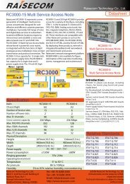
ADSL<br />
Mark<br />
ADSL2+<br />
<strong>ST330</strong> <strong>xDSL</strong> <strong>Tester</strong><br />
Specifications<br />
ADSL Modem<br />
ADSL2+ Modem(ADSL/ADSL2/READSL)<br />
1. Summarization<br />
<strong>ST330</strong> is designed for present all kinds of <strong>xDSL</strong> line including ADSL,<br />
ADSL2, ADSL2+, READSL. It not only can test <strong>xDSL</strong> physical layer<br />
parameter and also can help you to confirm whether your line is proper<br />
to provide <strong>xDSL</strong> service. It also can evaluate your line quality. It also can<br />
have PPPoE dial, do IE network page browsing, and emulate user’s PC+<br />
Modem by inside Modem of <strong>ST330</strong> to test the connection between user<br />
and ISP provider. You can have all kinds of test such as Ping, Ipconfig,<br />
Rouge, Tracert after successful dial. <strong>ST330</strong> also can emulate the user’s<br />
PC to test broadband IP line or have PPPoE dial by user’s Modem to test<br />
the connection of IP network and Modem problem or to remove the<br />
problem arisen by computer.<br />
<strong>ST330</strong> takes 240X320 TFT true color LCD, touching screen and<br />
embedded system. So it is easy to operate and to see the test result.<br />
2. Checking the contents of the package<br />
Unpack the box and check the contents before operating the instruments.<br />
If some of the contents are not correct or missing or if there is physical<br />
damage, contact our company and the dealer from which you purchased<br />
them. If you are adding or replacing the standard or optional accessories<br />
indicated below, make sure to purchase them from us or your dealer.<br />
Check that the model name and suffix code given on the name plate on<br />
the back of tester.<br />
Model Suffix Code Specifications<br />
-CN<br />
Chinese<br />
<strong>ST330</strong> -EN English<br />
Standard accessories<br />
The following standard accessories are supplied with the instrument.<br />
Check whether all the contents are attached and undamaged.<br />
Charger Direct Ethernet Test cord LCD protective board Touching<br />
Network line stick<br />
User manual List Carry case Handle<br />
Optional accessories<br />
The following optional accessories are available for purchase separately.<br />
When you receive the order, Check whether all the contents are attached<br />
and undamaged.<br />
Keyboard which can be linked to tester USB port<br />
Mouse which can be linked to tester USB port<br />
Memory key<br />
3. Safety<br />
Make sure to comply with the following safety precautions.<br />
Not complying might result in injury or death.<br />
WARNING<br />
5<br />
6
7<br />
<strong>ST330</strong> <strong>xDSL</strong> <strong>Tester</strong><br />
Power Supply<br />
Ensure that the source voltage matches the voltage of the power<br />
supply or else maybe there will be some damage to the <strong>Tester</strong>.<br />
Battery changing<br />
Please refer to the 7.10 item.<br />
Do Not Operate in Explosive Atmosphere<br />
Do not operate the instrument in the presence of flammable liquids<br />
or vapors. Operation of any electrical instrument in such an<br />
environment constitutes a safely hazard.<br />
Back cover<br />
Do not separate the top and bottom cover unless you are replacing the<br />
battery or Modem. Battery replacement should only be carried out by<br />
a person who received proper training. Some areas inside the<br />
instrument have high voltage that is dangerous if they are not<br />
handled properly.<br />
LCD<br />
If, by accident, the surface of the LCD is damaged and the liquid, or<br />
let it touch the skin. If the liquid happens to come in contact with the<br />
eye or the mouth, immediately rinse with water. If it comes in contact<br />
with the skin or clothes, wipe it with alcohol and then wash it with<br />
soap and water. Otherwise, damage to the skin or clothes may result.<br />
In addition, be careful not to cut the skin (fingers, hands, etc) with the<br />
broken glass. Touching the edges of the broken glass can cause<br />
injury.<br />
4. Notice in operation and using<br />
4.1 General operation precautions<br />
Test Interface<br />
Please firstly connect the test cord to <strong>ST330</strong> test interface and then<br />
connect to the test line. Please don’t touch the metal pars of clamps<br />
to avoid the high dangerous voltage.<br />
USB port<br />
8<br />
<strong>ST330</strong> <strong>xDSL</strong> <strong>Tester</strong><br />
Don’t input things with electricity to USB port and please don’t short it<br />
by metal things.<br />
Display screen<br />
Protective board and film are affixed to the LCD at the time of<br />
shipment. Please remove it before use.<br />
Cleaning<br />
The instrument uses many plastic parts. When cleaning, wipe using<br />
a dry soft cloth. Do not use volatile chemicals since this might cause<br />
discoloring and deformation.<br />
Protecting the case and operating panel<br />
Do not pour volatile agents on the case or operation panel, this can l<br />
ead to malfunctioning.<br />
When moving the instrument<br />
Check that the power cord and connection cables are removed.<br />
After use, unplug the power cord from the socket.<br />
When the instrument is not used for a long period of<br />
time<br />
When the instrument is not used for a long period of time, the<br />
battery characteristics may have deteriorated. The battery also may<br />
take longer to charge. If the operation period of fully charged battery<br />
is excessively short, the battery must be replaced. To replace the<br />
battery, see the “Battery Replacement Manual”.<br />
Malfunction<br />
Never continue to use the instrument if there are any symptoms of<br />
trouble such as strange sounds, odors, or smoke coming from the<br />
instrument. In such cases, immediately turn OFF the power and<br />
unplug the power cord. If the instrument has malfunctioned, contact<br />
your dealer.<br />
4.2 Suggestion for using<br />
<br />
<br />
Please charge the battery full before your first using and usually<br />
using. Please refer to 7.9 item about charging.<br />
When you operate function keys, please use touching stick and<br />
please click LCD proper.
<strong>ST330</strong> <strong>xDSL</strong> <strong>Tester</strong><br />
If there is any abnormal phenomenon, please press RESET key to<br />
reset or press OFF key to switch on again.<br />
Please don’t put the instrument under the strong direct sunlight and<br />
near the origin of heat. Or else, there will be bad affect to circuit.<br />
Condensation may occur if the instrument is moved to another place<br />
where the ambient temperature is higher, or if the temperature if the<br />
room changes rapidly. In this case, let the instrument adjust to the<br />
new environment for at least one hour before using the instrument.<br />
Using the instrument near strong magnetic field sources will have<br />
adverse affects on the internal circuit of the instrument.<br />
If you are using a portable phone to transmit measured data, move<br />
the portable phone at least 1 m away from the instrument and<br />
Measuring Cables. The measured data can receive undesirable<br />
effects from the electromagnetic wave generated by the portable<br />
phone.<br />
<strong>ST330</strong> <strong>xDSL</strong> <strong>Tester</strong><br />
5. System configuration and quick reference<br />
5.1 System configuration<br />
<br />
<br />
<strong>xDSL</strong> Port:For user <strong>xDSL</strong> line link and DMM test link.<br />
LAN Port:Ethernet port.<br />
<br />
<strong>xDSL</strong> Modem:Different Modem can perform different function.<br />
Mainly include ADSL,<br />
ADSL2, ADSL2+, READSL, VDSL, etc.<br />
<br />
USB HOST:Link USB equipment, keyboard, mouse and<br />
memory key.<br />
5.2 Quick reference<br />
5.2.1<strong>ST330</strong> Front Panel<br />
9<br />
10
<strong>ST330</strong> <strong>xDSL</strong> <strong>Tester</strong><br />
<strong>ST330</strong> <strong>xDSL</strong> <strong>Tester</strong><br />
5.2.2 <strong>ST330</strong> Up side<br />
Indicator Lights<br />
Buttons<br />
<br />
<br />
<br />
<br />
<br />
<br />
<br />
Power Indicator Light<br />
Red color, power supplied<br />
Ethernet Indicator Light:<br />
Green color, normal Ethernet connection<br />
Shining green color, Ethernet data transmission<br />
<strong>xDSL</strong> LINK Indicator Light<br />
Shining green color, <strong>xDSL</strong> Modem being connected<br />
Green color, <strong>xDSL</strong> connected.<br />
<strong>xDSL</strong> ACT Indicator Light<br />
Shining green color, <strong>xDSL</strong> data transmission.<br />
ON<br />
Switch on tester.<br />
OFF<br />
Switch off tester when there are abnormal phenomena,<br />
such as tester dead or slow run speed.<br />
RESET<br />
Reset system when there is an abnormal<br />
phenomenon occurs.<br />
LCD Display<br />
TFT true color screen, 240×320 lattice, touching screen.<br />
11<br />
Touching stick<br />
Use it to point icons from display screen to have operation.<br />
Insert it into left up corner of tester when it is not used.<br />
Ethernet port 1<br />
It is RJ45 port. It is for linking Ethernet network cord or<br />
Broadband IP with RJ45 network line plugs. It is for cross<br />
network cord link.(NOTE:Ethernet port 1 and 2 cannot be<br />
meantime)<br />
used<br />
Ethernet port 2<br />
It is RJ45 port. It is for linking Ethernet network cord or<br />
Broadband IP with RJ45 network line plugs. It is for direct<br />
network cord link.(NOTE:Ethernet port 1 and 2 cannot be<br />
meantime)<br />
used<br />
<strong>xDSL</strong> port<br />
It is the port for both <strong>xDSL</strong> line and DMM test. There are<br />
two connection ways.<br />
One is standard RJ11 port. It is for linking RJ11 port.<br />
The other one is red & black port. It is for linking test cords.<br />
These two ports are connected inside of the tester. User<br />
can use any one.<br />
12
5.2.3 <strong>ST330</strong> Down side<br />
<strong>ST330</strong> <strong>xDSL</strong> <strong>Tester</strong><br />
<strong>ST330</strong> <strong>xDSL</strong> <strong>Tester</strong><br />
be linked to tester. It can be linked directly to Ethernet port<br />
when to link IP network line. When the Ethernet connection<br />
is normal, the ETHERNET indicator light will be bright.<br />
6. Functions and specifications<br />
6.1 <strong>xDSL</strong> test<br />
5.2.4 Other parts<br />
USB Port<br />
To link memory key, keyboard or mouse. When to link<br />
2 1<br />
memory key, it is used to upgrade tester software or<br />
exchange record file with tester; when to link keyboard, it is<br />
used as normal keyboard to type words; when to link<br />
mouse, it is used as normal mouse to carry out operation.<br />
Charger Port<br />
To link charger to charge inner battery.<br />
LCD screen protection board<br />
To protect LCD screen during storage or long distance<br />
delivery. Please take it down and put it in the back of tester<br />
when you use the tester.<br />
Test cord<br />
Connect tester and the line using test cord. Please do not<br />
touch clamp metal to avoid dangerous.<br />
Charger port<br />
50Hz, AC220V<br />
Error range is±10%<br />
Output is 8.4V<br />
There is one indicator light in charger. If it is in red color, it<br />
means the tester is being charged; when it is in green color,<br />
it means the battery is fully charged.<br />
Ethernet cord<br />
The network line attached with tester is direct one, and it is<br />
used for connection with hub. Cross network line also can<br />
13<br />
Perform physical layer parameter test, network layer test and application<br />
layer test to confirm whether there is fault in user line or not.<br />
1. Physical layer test specifications<br />
G.SHDSL module<br />
1) Standard: ITU-T G.991.2 (G.SHDSL), Test Mode: STU-C<br />
STU-R; or<br />
2) Test DSL line transmission parameters<br />
Error Statistic<br />
1) ErrosrsLOSW<br />
Port Bitrate : 0~2320kbps<br />
Noise Margin(SNRM):0~35.7dB<br />
Attenuation ATTN:0~37.0dB<br />
XmitPower:0~13.5dB<br />
CRC Error<br />
SEGA Error<br />
ES<br />
SES<br />
UAS<br />
14
LOSWS<br />
<strong>ST330</strong> <strong>xDSL</strong> <strong>Tester</strong><br />
DSL line up channel speed (Mbps):0~1<br />
<strong>ST330</strong> <strong>xDSL</strong> <strong>Tester</strong><br />
ADSL2+ module<br />
1) Standard: ITU G.994.1(G.hs), ITU G.992.5, ITU<br />
G.992.5 Annex L.<br />
Be compatible with ADSL, ADSL2 and READSL ADSL.<br />
2) DSL line transmission parameter:<br />
DSL line attenuation (dB):0~63.5<br />
DSL line noise margin (dB):0~32<br />
DSL line up channel speed (Mbps):0~1.2<br />
DSL line down channel speed (Mbps):0~24<br />
DSL line up/down maximum rate and capacity ratio<br />
DMT sub channel bit number: 0~15<br />
DSL line error number (CRC, HEC, FEC, NCD, OCD)<br />
DSL line local output power<br />
State display: signal loss, connection close.<br />
ADSL2 module<br />
DSL line down channel speed (Mbps):0~8<br />
DSL line error number (CRC, HEC, FEC, NCD, OCD)<br />
DSL line local output power<br />
DSL line connection mode<br />
2. PPPoE dial and PPPoE dial properties change<br />
To emulate user MODEM and PC to have PPPoE dial.<br />
3. Network layer test (Ping, Ipconfig, Tracert and Route)<br />
4. IE Webpage browsing test function<br />
6.2 LAN test<br />
Perform PPPoE dial test of LAN or Broadband IP; network layer<br />
and application layer test of LAN; search PC in network.<br />
<br />
<br />
<br />
<br />
6.3 DMM test<br />
LAN port PPPoE Dial and properties change function.<br />
Network layer test (Ping, Ipconfig, Tracert and Route).<br />
Fixative IP scanning function.<br />
Webpage browsing function.<br />
Test user line AC/DC Voltage, Loop Resistance, Capacitance and<br />
Insulation.<br />
1) Standard: ITU G.992.1(G.DMT), ITU G.992.2 (G. lite),<br />
ITU G.994.1 (G.hs)<br />
ANSI T1.413 issue #2<br />
2) DSL line transmission parameter:<br />
DSL line attenuation (dB):0~63.5<br />
DSL line noise margin (dB):0~32<br />
15<br />
Voltage<br />
Unit Test Range Error<br />
0--100 DC ±2%<br />
V 100--200 DC ±5%<br />
200--400 DC ±5%<br />
16
<strong>ST330</strong> <strong>xDSL</strong> <strong>Tester</strong><br />
<strong>ST330</strong> <strong>xDSL</strong> <strong>Tester</strong><br />
Loop<br />
Resistance<br />
V<br />
Ω<br />
0—100 AC ±2%<br />
100--400 AC ±5%<br />
0—100 ±3%<br />
100—500 ±3%<br />
500—2000 ±2%<br />
7.1 Switch on/off, restart<br />
(1) Switch on: Press ON button in the right of instrument to switch on the<br />
tester. After 7 seconds, operation window will be displayed.<br />
2000—20K ±2%<br />
Capacitance<br />
nF<br />
0—10 ±2 nF<br />
10—1000 ±2%<br />
Insulation<br />
MΩ<br />
0—1.0 ±0.1 MΩ<br />
1.0—50 ±10%<br />
6.4 Modem emulation<br />
Perform MODEM Emulation function to dial and log on internet to check<br />
faults.<br />
6.5 File management<br />
Browse test record, transfer record into PC or memory key.<br />
6.6 Help<br />
This part includes the system upgrade, function set, recalibrate and use<br />
notes. The system software can be upgrade by Ethernet or memory key.<br />
6.7 Other specifications<br />
Memory capacity: 20 M<br />
Display:<br />
240×320 LCD, touch screen,<br />
Windows interface<br />
Power Supply External: From adapter, 9.6V DC<br />
Internal: Rechargeable 7.4 V 2100mAH Li-ion battery<br />
Battery Duration: 8hs (except Modem status)<br />
Dimensions/Weight: 176mm×130mm×60mm/0.7kg(With battery)<br />
(2) Switch off: Point Close System icon from operation interface, point<br />
OK to switch off the tester from the window displayed.<br />
(3) OFF button: Press it in the right of the instrument to switch off the<br />
tester when there is abnormal operation phenomenon occurred.<br />
Suggestion: Switch off tester through system.<br />
(4) RESET button: Press it to restart the tester when there is slow run<br />
speed or tester dead phenomenon.<br />
7.2 Operation interface description<br />
The main operation interface is divided into 3 parts.<br />
7.2.1 State bar<br />
7. Operation<br />
17<br />
18
<strong>ST330</strong> <strong>xDSL</strong> <strong>Tester</strong><br />
<strong>ST330</strong> <strong>xDSL</strong> <strong>Tester</strong><br />
Input Panel<br />
Point to display or hide Input Panel.<br />
To input lowercase, number and interpunction.<br />
Battery: Show battery energy. It is divided into 3 parts. Please charge<br />
it soon when all 3 parts are empty.<br />
Time: Show the current time. Point it to set date and time.<br />
Point to enter into HELP window.<br />
Point Shift to input capital character and special symbols, parts of<br />
interpunction.<br />
Homepage<br />
Point it to return main operation interface.<br />
Back<br />
Point it to return upper interface.<br />
7.3 <strong>xDSL</strong> test<br />
You can change the current date and time by touching stick and press<br />
Apply key to save it.<br />
7.2.2 Function bar<br />
Point different icon to have relevant test operation.<br />
7.2.3 Tools bar<br />
PPPoE Disconnection icon.<br />
When dial is ok, change to . Point , to disconnect<br />
PPPoE connection from window displayed.<br />
19<br />
To validate DUN (DIAL-Up Networking) and test <strong>xDSL</strong> line performance<br />
through inside Modem.<br />
<strong>xDSL</strong> test Includes physical layer test, modem parameter set, PPPoE<br />
properties, PPPoE dial, network layer test, webpage browsing,<br />
LOOPBACK, FTP client and webpage speed test functions.<br />
The function can emulate the user side equipment to have PPPoE dial,<br />
network test and webpage browsing. And it also can judge the testing<br />
line quality by physical layer parameters. It can exclude the fault<br />
because of user side equipment.<br />
Two kinds of line link diagram:<br />
20
<strong>ST330</strong> <strong>xDSL</strong> <strong>Tester</strong><br />
<strong>ST330</strong> <strong>xDSL</strong> <strong>Tester</strong><br />
is bright, the physical layer test parameters need to be checked, please<br />
point it.<br />
7.3.1 Physical layer test<br />
Perform the test of the physical layer.<br />
Point to enter the physical layer test window.<br />
The function can validate whether the user line is good and also can<br />
solve the fault from user Modem and user PC by data parameters from<br />
user line.<br />
Link <strong>xDSL</strong> pair into RJ11 port directly or through <strong>xDSL</strong> separator. Point<br />
<strong>xDSL</strong> Test to enter into operation window.<br />
7.3.1.1 Physical layer parameters<br />
Test <strong>xDSL</strong> line physical layer parameter. It includes <strong>xDSL</strong> connecting State,<br />
connecting Mode, Up/Down Stream Speed, Noise Margin, Attenuation,<br />
Output Power, CRC Error, CRC Error, HEC Error, FEC Error, OCD Error,<br />
NCD Error and Channel Bit pic.<br />
Point different icons to have relevant test operation.<br />
The steps for logon webpage by <strong>xDSL</strong> line, like following:<br />
(1) Point Physical Layer Test, the Preparing test environment<br />
Window will be displayed, please wait for seconds till to enter into<br />
operation window.<br />
Set Modem parameter (VPI/VCI)→Set Properties(Security)<br />
PPPoE<br />
→PPPoE Dial(Have PPPoE dial When the Link indicator is bright, Type<br />
user name and password)→ browse webpage or have network layer<br />
test.<br />
If it needs to test possibility of connection between Modem and OE<br />
(Office End), no set steps need to be done. If the <strong>xDSL</strong> Act indicator light<br />
21<br />
22
G992.1 standard;<br />
with ITU-T standard;<br />
G992.3<br />
G.DMT.BISPLUS:ADSL2+ G.DMT.BISPLUS protocol mode ,<br />
<strong>ST330</strong> <strong>xDSL</strong> <strong>Tester</strong><br />
ADSL2+ physical layer ADSL2+ physical layer<br />
parameters 1 parameters 2<br />
<strong>ST330</strong> <strong>xDSL</strong> <strong>Tester</strong><br />
G.LITE:ADSL G.LITE protocol mode,in accordance with ITU-T<br />
standard;<br />
G992.2<br />
T1.413:ADSL T1.413 protocol mode,in accordance with ANSI<br />
T1.413 issue1 & Issue 2 standard.<br />
G.DMT.BIS:ADSL2 G.DMT.BIS protocol mode,in accordance<br />
ADSL Physical layer parameters<br />
Every parameter value will be displayed. They will be refreshed in real<br />
time to show the current state. The connection process of <strong>xDSL</strong> line and<br />
OE (Office End) equipment will be displayed from State bar (Idle,<br />
Handshake, Training, and Showtime); the current connection mode will<br />
be displayed from Mode bar.<br />
A. Current mode interpretation<br />
Idle: no connection or trying to do connection.<br />
HandShake: perform handshaking.<br />
Discovery: the OE DSLAM is found.<br />
Training: in the training of the connection.<br />
Showtime: Remote DSLAM connected.<br />
B. Connection mode interpretation<br />
in accordance with ITU-T G992.5<br />
C. Physical layer parameters interpretation<br />
Activate times: It counts the modem activated times from the beginning<br />
of the test. Once the modem is activated the number will tally up.<br />
Test time: It will show the test time after the modem is initialized.<br />
(2) Point Channel Bit pic, the Channel Bit pic will be displayed in red<br />
color.<br />
ADI:ADSL mode; ADI<br />
G.DMT:ADSL G.DMT protocol mode, in accordance with ITU-T<br />
Now the user can see the bit value of current connection which can also<br />
be displayed in map. If user needs to see the results in text you can point<br />
the then the following window will be displayed.<br />
23<br />
24
<strong>ST330</strong> <strong>xDSL</strong> <strong>Tester</strong><br />
<strong>ST330</strong> <strong>xDSL</strong> <strong>Tester</strong><br />
Click entering physical layer test window<br />
(3) Point Cancel to close bit map window.<br />
(4) Point Cancel from Physical layer Test window, one test record<br />
window will be displayed.<br />
(5) Point Cancel if you do not save record.<br />
(6) Point OK if you save the record.<br />
G.SHDSL physical layer parameters<br />
All the parameters on the display window will renew along with the test<br />
time changing to reflect the present situation<br />
Present Status:<br />
Idle:Not connecting or connecting<br />
Handshake: Handling<br />
Discovery:Find DSLAM<br />
The default file name is linexxxx-xxx.phy, in which “x” means the<br />
number. User can modify the line number as telephone number.<br />
Training: Connecting training<br />
Showtime: Distance DSLAM connection successfully.<br />
7.3.1.2 G.SHDSL Modular<br />
The physical parameters of DSL line includes XDSL port mode, present<br />
status, port rate, noise margin rate, attenuation, XmitPower, frame synch<br />
lost, circulation redundancy lost, subsection abnormal, error, serious<br />
error and frame synch.<br />
25<br />
Click “off” button can close the window. If we click “off” button on the<br />
window of Physical layer, we will close the physical layer window. At the<br />
same time, it will indicate “Save test result or not”, if we do not need to<br />
save result, we can click cancel. If we press “ok”, we will enter the result<br />
save window.<br />
26
<strong>ST330</strong> <strong>xDSL</strong> <strong>Tester</strong><br />
The default file name of test result is xxxxxxxx-xxx.phy, x is number. The<br />
user can modify file name to line’s phone number.(We also suggest you<br />
modify the number as to your phone numer, it is easier to remember.)<br />
<strong>ST330</strong> <strong>xDSL</strong> <strong>Tester</strong><br />
7.3.1.3 Noise curve<br />
It used to browse the real time noise margin curve.<br />
Point noise margin icon it will display the following noise curve<br />
picture.<br />
7.3.2 Modem parameter set<br />
7.3.2.1 ADSL2/ADSL2+ modular<br />
The function is to modify <strong>xDSL</strong> Modem parameters, VPI/VCI values.<br />
(1) Point MODEM Parameter to enter into operation window.<br />
This part contains up stream noise margin curve and down stream noise<br />
margin curve. They are reflects the noise margin varies as the time pass.<br />
If user press “upstream” or “downstream” at the top of thewindow the<br />
below real time picture will change.<br />
ADSL2+ Module Setting Window ADSL Module Setting Window<br />
(2) The VPI/VCI parameters which were set before will be displayed. If it<br />
needs to be modified, type new VPI/VCI value from VPI and VCI bar.<br />
Point OK, and the Modem VPI/VCI will be set.<br />
When the MODEM is ADSL2+, it also can be set as ADSL compatible<br />
27<br />
28
<strong>ST330</strong> <strong>xDSL</strong> <strong>Tester</strong><br />
mode.<br />
ADSL2+ Mode: It is standard ADSL2+ mode. The current connection<br />
mode can be automatically chosen according to OE mode.<br />
ADSL Compatible Mode: The ADSL2+ connection mode is unavailable<br />
under such mode.<br />
<strong>ST330</strong> <strong>xDSL</strong> <strong>Tester</strong><br />
7.3.2.2 G. SHDSL modular<br />
Functions<br />
Modify XDSL Modem parameters, especially for VPI/VCI values.<br />
Usage<br />
When we need to modify Modems’ parameters, click , entering<br />
Modem parameters setting windows, like the following picture.<br />
If the MODEM Mode is modified as another kind of it, please exit the<br />
<strong>xDSL</strong> Test and re-enter it again.<br />
Notice<br />
(1) In the ADSL2+ Module, if the MODEM Mode is modified as another<br />
kind of it, please exit the <strong>xDSL</strong> Test and re-enter it again. Otherwise, the<br />
MODE Modifying will not be effective.<br />
G.SHDSL modular modem G.SHDSL mode setting window<br />
Parameter setting<br />
(2) The VPI/VCI parameters which were set before will be displayed. If it<br />
needs to be modified, type new VPI/VCI value from VPI and VCI bar.<br />
Point OK, and the Modem VPI/VCI will be set.<br />
Entering the window, the tester will display 7 groups VCI/VPI parameters<br />
on the window. If we need to modify them, we can input the value directly<br />
then press “OK”.<br />
G.SHDSL mode: We can set the tester as the DSLAM or user terminal<br />
mode as the test situation.<br />
Present mode: display present setting mode of Modem I the tester. Like<br />
the following windows<br />
29<br />
30
<strong>ST330</strong> <strong>xDSL</strong> <strong>Tester</strong><br />
<strong>ST330</strong> <strong>xDSL</strong> <strong>Tester</strong><br />
After Modem mode’s modification, pls exit to <strong>xDSL</strong> test, and enter <strong>xDSL</strong><br />
test again. It can make sure Modem initialization to active modified<br />
mode.<br />
7.3.3 PPPoE properties<br />
Check and modify PPPoE Dial Properties set.<br />
(1) Point PPPoE Properties icon to enter the operation window.<br />
Choose Unencrypted password (PAP) and Preview user name and<br />
password, cancel other options. Point OK to set it. Point from<br />
Connection window to close these windows.<br />
.<br />
Notice<br />
there is wrong PPPoE set, PPPoE dial will be failed. Please be<br />
careful to modify PPPoE properties.<br />
other parameters have already been well set. Please do not<br />
modify or delete anything except PPPoE to avoid fail use of network card<br />
and PPPoE Dial.<br />
7.3.4 PPPoE dial<br />
To build PPPoE Dial connection through inside <strong>xDSL</strong> Modem.<br />
● If<br />
(1) Point PPPoE Dial to enter into operation window.<br />
● All<br />
Point Security Settings… to enter into operation window.<br />
31<br />
(2) Type user name and password from the User Name and Password<br />
32
<strong>ST330</strong> <strong>xDSL</strong> <strong>Tester</strong><br />
bar. The “save password” default option is selected and can not be<br />
revised. Please keep Domain column be blank, otherwise, the PPPoE<br />
Dialing will be failed.<br />
(3) Keep Domain be black. Point OK, displays like following:<br />
<strong>ST330</strong> <strong>xDSL</strong> <strong>Tester</strong><br />
(4) After PPPoE Dial connected, will become as , if it needs to<br />
be disconnected, point<br />
point Cancel to disconnect it.<br />
, the connection window will be displayed,<br />
7.3.5 Network layer test<br />
After the PPPoE Dial connection through inside Modem, to have<br />
Network Layer Test (Ping, Ipconfig, Tracert and Route test).<br />
(2) Type IP address or domain name into Destination bar.<br />
(3) Choose the data package size in the data package size bar.<br />
(4) Choose Ping times from Test times. The default Ping times is 5<br />
times.<br />
(5) Point OK, the Ping test process will be displayed in dynamic.<br />
(6) When the Ping test result window displayed, point which is in the<br />
right top corner of screen to close the window.<br />
7.3.5.2 IPCONFIG test<br />
The current TCP/IP, network configuration value, DHCP and DNS set will<br />
be displayed.<br />
(1) Point IPCONFIG Test to enter into operation window.<br />
(1) Point Network Layer Test to enter into operation window.<br />
(2) Point different icon to have relevant test operation.<br />
7.3.5.1 PING test<br />
(1) Point PING Test to enter into operation window.<br />
33<br />
(2) Choose Ipconfig Parameter from Ipconfig Parameter bar, point OK<br />
to have Ipconfig test.<br />
(3) One test result window will be displayed. Point from the right top<br />
corner of screen to close the window after the Ipconfig result window<br />
displayed.<br />
34
7.3.5.3 ROUTE test<br />
(1) Point ROUTE Test to enter into operation window.<br />
<strong>ST330</strong> <strong>xDSL</strong> <strong>Tester</strong><br />
<strong>ST330</strong> <strong>xDSL</strong> <strong>Tester</strong><br />
(3) One Tracert result window will be displayed. Point from the right<br />
top corner of screen to close the window after the Tracert result window<br />
displayed.<br />
7.3.6 Webpage browse<br />
Logon and browse webpage.<br />
(1) Point Webpage Browse to open webpage browser<br />
(2) Choose Route Parameter from Parameter set and point OK to have<br />
Route test. The default one is Print.<br />
(3) One Route result window will be displayed. Point from the right<br />
top corner of screen to close the window after the Route result window<br />
displayed.<br />
7.3.5.4 TRACERT test<br />
(1) Point TRACERT Test to enter into operation window.<br />
(2) Point Address bar, the Input Panel will be displayed.<br />
(2) Type address or web address in Destination bar, choose parameter<br />
from Tracert bar, point OK to have Tracert Test.<br />
35<br />
(3) Type website address and point Enter using input panel to<br />
logon the web site.<br />
36
<strong>ST330</strong> <strong>xDSL</strong> <strong>Tester</strong><br />
7.3.7 LOOPBACK test<br />
Ping Test for F5 OAM of ATM layer to verify ATM layer connection.<br />
Point Loopback Test icon to enter into operation window.<br />
<strong>ST330</strong> <strong>xDSL</strong> <strong>Tester</strong><br />
(2) Fill the IP address of the website will be tested in to the address bar<br />
and also the username and password then point the connect key to enter.<br />
(3) Point the parameter key to select the FTP mode and port.<br />
(4) The left blanket is the listing of the Local catalog while the right one is<br />
the listing of the remote catalog. And the connection state will be<br />
displayed at the down left corner.<br />
(5) Point to enter the FTP connection parameter setting.<br />
Choose PVC access, point Test to have its LOOPBACK test. The test<br />
result will be displayed. Test Result: Success or fail<br />
Notice:<br />
The PVC chosen by user should be the same as line VPI/VCI, otherwise,<br />
the Loopback Test will be failed.<br />
7.3.8 FTP client<br />
The tester can provide the FTP client function test.<br />
(1) Point FTP Client icon to open the following FTP client<br />
window.<br />
The user can set the port and connection mode<br />
7.3.9 Webpage speed test<br />
The webpage speed test is used to validate the network flux.<br />
(1) Point Web Speed test icon to open the speed test window.<br />
37<br />
38
<strong>ST330</strong> <strong>xDSL</strong> <strong>Tester</strong><br />
(2) Input the website IP address into the address bar. Then press the test<br />
key to start the website speed test. The results will be displayed in form<br />
of picture or text according the option.<br />
<strong>ST330</strong> <strong>xDSL</strong> <strong>Tester</strong><br />
Emulate tester as user PC to have PPPoE DUN (Dial-Up Networking). It<br />
includes Network Card Properties, PPPoE Properties, PPPoE Dial,<br />
Network Layer Test(Ping, Ipconfig, Route and Tracert), Fixative IP Scan,<br />
Webpage Browse, FTP client and webpage speed test functions.<br />
(1) Point LAN Test to enter into operation window.<br />
Result in picture Result in text<br />
Attentions:<br />
1. In LAN test the user should set the gateway and DNS while in <strong>xDSL</strong><br />
test canceling the gateway and DNS setting is necessary and connected<br />
through PPPoE.<br />
2. Please do notice that fill the right address into the address bar. It can<br />
not get good effect while testing the website which is used to make<br />
address jump at the server.<br />
7.4 LAN test<br />
For Ethernet and Broadband IP network test.<br />
(2) Point different icon to have relevant test operation.<br />
7.4.1 Network card properties<br />
Check and modify network card properties, including IP address,<br />
gateway and DNS.<br />
(1) Point Network Card to enter into operation window.<br />
39<br />
40
<strong>ST330</strong> <strong>xDSL</strong> <strong>Tester</strong><br />
(2) User can modify IP address, gateway and DNS value from IP<br />
address, Default and DNS bar separately. Point OK to save it and point<br />
Cancel to close it.<br />
7.4.2 PPPoE properties<br />
Check and modify PPPoE Security settings of PPPoE Properties.<br />
(1) Point PPPoE Properties to enter into operation window.<br />
<br />
<strong>ST330</strong> <strong>xDSL</strong> <strong>Tester</strong><br />
If there is wrong PPPoE set, PPPoE dial will be failed.<br />
Please be careful to modify PPPoE properties.<br />
<br />
All other parameters have already been well set.<br />
Please do not modify or delete anything except PPPoE to<br />
avoid fail use of network card and PPPoE Dial.<br />
7.4.3 PPPoE dial<br />
Build PPPoE Dial through outside Modem.<br />
(1) Point PPPoE Dial to enter into operation window.<br />
(2) Point Security Settings…to enter into operation window.<br />
(2) Type user name and password from User Name and Password bar<br />
separately. Choose Save password to save it. The save password<br />
option is default and can not be revised.<br />
(3) Keep Domain bar be black. Point OK to have DUN (Dial-Up<br />
Networking).<br />
(3) Choose Unencrypted Password (PAP) and Preview user name<br />
and password, cancel other options. Point OK to set it.<br />
(4) Point from Connection window to close it.<br />
Notice<br />
41<br />
(4) After PPPoE Dial connected, will become as , if it needs to<br />
be disconnected, point , the connection window will be displayed,<br />
42
point Cancel to disconnect it.<br />
<strong>ST330</strong> <strong>xDSL</strong> <strong>Tester</strong><br />
7.4.4 Network layer test<br />
After the PPPoE Dial connection through inside Modem, to have<br />
Network Layer Test (Ping, Ipconfig, Tracert and Route test).<br />
(1) Point Network Layer Test to enter into operation window.<br />
<strong>ST330</strong> <strong>xDSL</strong> <strong>Tester</strong><br />
(4) Point OK, the Ping test process will be displayed in dynamic.<br />
(5) When Ping test result window displayed, point which is in the<br />
right top corner of screen to close the window.<br />
7.4.4.2 IPCONFIG test<br />
The current TCP/IP, network configuration value, DHCP and DNS set will<br />
be displayed.<br />
(1) Point IPCONFIG Test to enter into Ipconfig test window.<br />
(2)Point different icon to have relevant test operation.<br />
7.4.4.1 PING test<br />
PING Test to enter into operation window.<br />
(2) Choose Ipconfig Parameter from Ipconfig Parameter bar, point<br />
OK to have Ipconfig test.<br />
(3) One test result window will be displayed. Point from the right<br />
top corner of screen to close the window after the Ipconfig result window<br />
displayed.<br />
7.4.4.3 ROUTE test<br />
(1) Point ROUTE Test to enter into operation window.<br />
(1) Point<br />
(2) Type IP address or domain name into Destination bar. Choose Ping<br />
times from Test times. The default Ping times is 5 times.<br />
(3) Select data package size in the data package size bar.<br />
43<br />
44
<strong>ST330</strong> <strong>xDSL</strong> <strong>Tester</strong><br />
(2) Choose Route Parameter from Parameter set and point OK to<br />
have Route test. The default one is Print.<br />
(3) One Route result window will be displayed. Point from the<br />
right top corner of screen to close the window after the Route result<br />
window displayed.<br />
7.4.4.4 TRACERT test<br />
<strong>ST330</strong> <strong>xDSL</strong> <strong>Tester</strong><br />
(1) Point TRACERT Test to enter into operation window.<br />
(2) Link Ethernet network line well, the Ethernet indicator light will be<br />
bright.<br />
(3) Point OK to search PC which is in the same network part and LAN.<br />
The IP address and PC name will be displayed once one PC is<br />
searched.<br />
7.4.6 Webpage browse<br />
Logon and browse webpage.<br />
(2) Type address or web address in Destination bar, choose parameter<br />
from Tracert bar, point OK to have Tracert Test.<br />
(3) One Tracert result window will be displayed. Point from the right<br />
top corner of screen to close the window after the Tracert result window<br />
displayed.<br />
7.4.5 Fixative IP test<br />
To scan PC which is in the same network part with tester in same LAN.<br />
The IP address and name of PC on line will be displayed.<br />
(1) Point Webpage Browse to open webpage browser.<br />
(1) Point Fixative IP to enter into operation interface.<br />
(2) Point Address bar, the Input Panel will be displayed.<br />
45<br />
46
<strong>ST330</strong> <strong>xDSL</strong> <strong>Tester</strong><br />
<strong>ST330</strong> <strong>xDSL</strong> <strong>Tester</strong><br />
(3) Point the Parameter key to select the FTP mode and port.<br />
(4) The left blanket is the listing of the Local catalog while the right<br />
one is the listing of the remote catalog. And the connection state will<br />
be displayed at the down left corner.<br />
(5) Point to enter the FTP connection parameter setting.<br />
(3) Type website address and point Enter using input panel to logon the<br />
web site.<br />
7.4.7 FTP client<br />
The tester can provide the FTP client test function.<br />
(1) Point FTP Client icon to open the following FTP client<br />
window.<br />
The user can set the port and connection mode.<br />
7.4.8 Webpage speed test<br />
The webpage speed test is for validating the network flux.<br />
(1) Point Web Speed test icon to open the speed test window.<br />
(2) Fill the IP address of the website will be tested in to the address<br />
bar and also the username and password then point the connect key<br />
to enter.<br />
47<br />
48
<strong>ST330</strong> <strong>xDSL</strong> <strong>Tester</strong><br />
<strong>ST330</strong> <strong>xDSL</strong> <strong>Tester</strong><br />
AC/DC Voltage, Loop Resistance, Capacitance and Insulation<br />
Resistance can be tested by built-in MΩ. The lineman will be informed<br />
whether there is dangerous voltage in the line or 48V voltage of tel line or<br />
not.<br />
(1) Point DMM Test to enter into operation window.<br />
(2) Input the website IP address into the address bar. Then press the test<br />
key to start the website speed test. The results will be displayed in form<br />
of picture or text according the option.<br />
Result in picture Result in text<br />
Attentions:<br />
(1) In LAN test the user should set the gateway and DNS while<br />
in <strong>xDSL</strong> test canceling the gateway and DNS setting is<br />
necessary and connected through PPPoE.<br />
(2) Please do notice that fill the right address into the address<br />
bar. It can not get good effect while testing the website which is<br />
used to make address jump at the server.<br />
7.5 DMM test<br />
49<br />
(2) Connect the test cord and the line which will be tested, point different<br />
icon to have relevant test operation.<br />
DC Voltage Test:<br />
To test whether there is signal in the test line or not. It only can be<br />
operated for DC voltage test. The test range is –262 ~262V. When it<br />
exceeds test range. The tester warns as “Over max”.<br />
AC Voltage Test:<br />
To test whether there is high AC voltage in the line or not in order to<br />
avoid dangers for lineman. When there is high AC voltage, please take<br />
off test clamp carefully.<br />
It is only for AC voltage test. The test range is -262~262V. When it<br />
exceeds the range, the tester warns as “Over max”.<br />
Loop Resistance Test:<br />
To calculate line length. If the line length is known, to adjust whether the<br />
line connection is right or not.<br />
Calculate line length using loop resistance value tested:<br />
50
<strong>ST330</strong> <strong>xDSL</strong> <strong>Tester</strong><br />
L=R L /R O(Km)---------------------------<br />
In expressions : R L is loop resistance value(Unit: Ω),R O is loop<br />
resistance value per kilo(Unit: Ω).<br />
For 0.32mm diameter of copper line, R O =435.2Ω; for 0.4mm diameter of<br />
copper line, R O =278.5Ω; for 0.5mm diameter of copper line, R O =178.3Ω.<br />
If it displays “Over max”, it means the test clamp is not well linked, or line<br />
is not loop linked, or the loop resistance exceeds range. Please check<br />
the test clamp or link the line well and have test again.<br />
<strong>ST330</strong> <strong>xDSL</strong> <strong>Tester</strong><br />
If there is voltage (>2V) in the line, it displays “AC in line”. It means<br />
there is voltage in the line, the insulation cannot be tested. Please check<br />
the line and have test when there is no voltage. If the line insulation<br />
resistance exceeds the range, it displays “〉50.0 MΩ”, it means the line<br />
insulation is good.<br />
(3) Point Cancel to close DMM test window. There is note message of<br />
test result storage. Press OK to save record and press Cancel to close<br />
it.<br />
If there is voltage (>2V) in the line, it displays “AC in line”. It means<br />
there is voltage in the line, the loop resistance cannot be tested. Please<br />
check the line and have test when there is no voltage.<br />
Capacitance Test:<br />
The line length can be calculated with capacitance tested if there is no<br />
bridge connection in the line and it is not soggy.<br />
L=C ab /C O (Km)。----------------------------------<br />
In the expression , C ab is capacitance value (Unit: nF), C O is<br />
capacitance value per kil (Unit: nF).<br />
If it displays “Over max” during the test process, it means the line<br />
capacitance exceeds range or there is fault in the line. Please check the<br />
line and have test again.<br />
If there is voltage (>2V) in the line, it displays “AC in line. It means there<br />
is voltage in the line, and the capacitance cannot be tested. Please<br />
check the line and have test when there is no voltage.<br />
Insulation Test:<br />
If there is small insulation resistance value, it means there is bad<br />
insulation in the line. The ADSL transmission performance will be<br />
influenced. The maintenance is required. ADSL line insulation resistance<br />
value should be more than 10MΩ.<br />
The default file name is linexxxx-xxx.dmm in which x is number. User<br />
can modify it as telephone number.<br />
Notice<br />
It is good for management that the line number of DMM record file name<br />
is the same as physical layer test record line number.<br />
7.6 Modem emulation<br />
Emulate user Modem to test whether there is fault in user Modem or not.<br />
(1)Point MODEM Emulation to enter into operation window.<br />
51<br />
52
<strong>ST330</strong> <strong>xDSL</strong> <strong>Tester</strong><br />
<strong>ST330</strong> <strong>xDSL</strong> <strong>Tester</strong><br />
(2)The tester will emulate user Modem to realize PPPoE DUN (Dial-Up<br />
Network).If the VPI/VCI value needs to be modified, please modify it<br />
from Modem Parameter window.<br />
(3)If it needs to exit Modem Emulation state, please point Exit MODEM<br />
Emulation Status! to exit it.<br />
NOTES<br />
Because of great power loss when the tester is in MODEM state. We<br />
limit the MODEM Emulation state in 15 minutes. If it exceeds 15 minutes,<br />
the MODEM will be switched off by tester automatically.<br />
(2) Point different icon to have relative test operation.<br />
7.7.1 Record browse<br />
Browse test record, including information of DMM test, physical layer<br />
parameter, and channel bit pic.<br />
(1) Point Record Browse to enter into operation window.<br />
7.7 File management<br />
To manage and check files save in tester, including record browse, save<br />
data in memory key and file transfer functions<br />
(1) Point File Management to enter into operation window.<br />
The file which postfix is “dmm” is the DMM test record; the file which<br />
postfix is “phy” is the physical layer test record.<br />
Choose the files which will be checked from select file dialog box and<br />
choose the needed recording file from the list. Then confirm and open<br />
the relevant file and the record will be displayed,<br />
DMM Test Record window:<br />
53<br />
54
<strong>ST330</strong> <strong>xDSL</strong> <strong>Tester</strong><br />
<strong>ST330</strong> <strong>xDSL</strong> <strong>Tester</strong><br />
Physical Layer Parameter Test Record window:<br />
ADSL module test record<br />
Point “Channel Bit Pic”, the channel bit pic will be displayed. Point<br />
Cancel button and close the window.<br />
7.7.2 Memory key save<br />
Transfer files saved in tester or memory key to each other. Make sure to<br />
insert memory key into tester, and the memory key is not in write-protect<br />
state.<br />
(1)Point<br />
Memory key Save to enter into operation window.<br />
ADSL2+ module test record 1 ADSL2+ module test record 2<br />
55<br />
(2) The file saved in tester will be displayed in the Local file bar; the file<br />
56
saved in memory key will be displayed in Remote file bar.<br />
<strong>ST330</strong> <strong>xDSL</strong> <strong>Tester</strong><br />
Notice<br />
<strong>ST330</strong> <strong>xDSL</strong> <strong>Tester</strong><br />
(3) Choose file from Local file bar, then point to transfer file<br />
into memory key;<br />
1. Please type in right format when the destination address is<br />
inputted.<br />
(4) choose file from Remote file bar, then point to copy file<br />
into tester.<br />
(5) Point Cancel to close the window.<br />
2. If it is the first time to visit destination address, the user<br />
name and password window will be displayed. If you have no<br />
user name and password, just point OK.<br />
7.7.3 File transfer<br />
Copy test record from tester to Share directory in other PC in LAN. Make<br />
sure the IP address of tester and PC are in the same network part, and<br />
there is one share directory.<br />
(1) Link network line into Ethernet port well, the Ethernet indicator light<br />
will be bright.<br />
7.7.4 File management<br />
Manage files saved in the tester, including file deletion and file<br />
transferring to memory key.<br />
(1) Point the File Management to enter the window:<br />
(2) Point File Transfer to enter into operation window.<br />
(2) Press to return to the root catalog.<br />
(3) Press to return the next higher level.<br />
(3) Type address into Input destination address bar, choose file will be<br />
transferred from Select file bar, point File Transfer, the file chosen will<br />
be transferred to the directory.<br />
(4) Press to copy the file to the memory key.<br />
57<br />
58
<strong>ST330</strong> <strong>xDSL</strong> <strong>Tester</strong><br />
<strong>ST330</strong> <strong>xDSL</strong> <strong>Tester</strong><br />
(5) Press to delete file.<br />
7.8 Help<br />
Providing information on system upgrading, operation, function setting,<br />
recalibrate and about.<br />
(1) Point HELP to enter into operation window.<br />
(2) User chooses software upgrade method from LAN and Memory<br />
key methods.<br />
(2) Point different icon to have relevant test operation.<br />
7.8.1 System upgrade<br />
There are two ways to upgrade the software.<br />
1. Upgrade software through LAN.<br />
2. Upgrade software through memory key.<br />
The test software can be downloaded through www.senter.com.cn.<br />
(1) Point System Upgrade to enter into System Upgrade<br />
window, to choose the upgrade mode.<br />
LAN mode<br />
(1) Make sure the IP address of tester and PC is in the<br />
same network part.<br />
(2) Copy the upgrade file from www.senter.com.cn to one<br />
share file.<br />
(3) Input route of upgrade file from LAN route bar, point<br />
OK.<br />
Memory key mode<br />
(1) Copy the upgrade file from www.senter.com.cn to the<br />
memory key.<br />
(2) Insert memory key into tester through USB port.<br />
Copy the upgrade file into the root directory of memory<br />
key, then click OK to complete the upgrade of the<br />
system.<br />
7.8.2 Use notes<br />
Introduce different kinds of function and operation way.<br />
(1)Point Use Notes to enter into operation window.<br />
59<br />
60
<strong>ST330</strong> <strong>xDSL</strong> <strong>Tester</strong><br />
<strong>ST330</strong> <strong>xDSL</strong> <strong>Tester</strong><br />
you close the tester setting will be the default automatic close.<br />
(5) Please do remember to press the set key to save your option.<br />
7.8.4 Recalibrate<br />
This part provides the accuracy recalibrating of screen response to the<br />
touching stick.<br />
(1) Point recalibrate icon to enter the recalibrate window.<br />
(2)Point different title to check introduction.<br />
7.8.3 Function set<br />
To perform the Manual close/ Automatic close switch set. The user can<br />
open/close timing switching off by this function set.<br />
(1) Point function set icon to enter the function set window.<br />
(2) Point to confirm the center of the screen. Then the will<br />
move to the four corners of the screen automatically. Please point the<br />
when it reach different corners to help the instrument to perform the<br />
(2)If you choose the Manual close option the instrument will be closed<br />
by yourself. If you do not close the instrument it will keep on open.<br />
(3)Once select Automatic close option the tester will auto switch off<br />
after 10 minutes’ idle to save power or 15 minutes modem emulation. We<br />
regard Automatic close as our default option in order to save power.<br />
(4) The revising of the switching off is effective in current operation. If<br />
61<br />
recalibrating of the screen’s different part. After the four corners is<br />
confirmed please point enter key to confirm the recalibrate setting.<br />
7.8.5 About<br />
Software vision and manufacturer information.<br />
Point About to check relevant information.<br />
62
<strong>ST330</strong> <strong>xDSL</strong> <strong>Tester</strong><br />
<strong>ST330</strong> <strong>xDSL</strong> <strong>Tester</strong><br />
7.9 Charge<br />
There is note message of low battery and it will be switched off<br />
automatically in 1 minute.<br />
(1) Switch off tester, insert charger input plug into AC 220V power supply,<br />
the indicator light will be green color.<br />
(2) Insert charger output plug into tester CHARGER port, the indicator<br />
light will be red color, it means the tester is being charged.<br />
(3) After the indicator light becomes green color, the tester has been fully<br />
charged. Please take off the charger.<br />
Step 2: Please release the 2 screws on back shell and pull the back<br />
shell backward vertically.<br />
7.10 Battery Replacement<br />
The battery is 7.4V 2700mAh Li battery and its measure is(W × L × H)<br />
≤ 46mm×99mm×14mm. And there is a 2mm bumper to help prevent<br />
collision between shell and battery. We (manufacturer) could provide<br />
new paying battery to replace the old to the customers. It is also OK to<br />
take the other factory’s battery which could meet requirements. But we<br />
suggest take the manufacturer’s battery. Please ask the professional<br />
staff to replace the battery by following steps.<br />
Step 1: Please release the 4 screws by “+” type screw driver on the back<br />
shell and pull the back shell backward vertically.<br />
Step 3: Unbolt the pin between battery and printed board. Then<br />
replace the old battery with the new one. And insert the battery pin<br />
into the X6 seat of the printed board. Please do notice that keep the<br />
anode & cathode in the right positions.<br />
63<br />
64
<strong>ST330</strong> <strong>xDSL</strong> <strong>Tester</strong><br />
<strong>ST330</strong> <strong>xDSL</strong> <strong>Tester</strong><br />
Step 4: Cover the body with back shell and screw on the two screws.<br />
inner Modem cannot be in<br />
please test whether there is<br />
2. If there is no voltage, it<br />
activation for long time<br />
48V voltage by DMM test<br />
means there is no service in<br />
function.<br />
the line.<br />
Failed modem initialization<br />
1. User set the network card<br />
properties as DHCP mode.<br />
2. User forbids the using of<br />
network card.<br />
1. Modify the network card<br />
properties and set a fixed IP<br />
address.<br />
2. Make network properties in<br />
normal status.<br />
After enter into <strong>xDSL</strong> test, the<br />
under voltage warning will be<br />
display in a very short time.<br />
The power of the Modem is<br />
big and the electricity will be<br />
consumed fast by the <strong>xDSL</strong><br />
test in the low power.<br />
Confirm the full charge when<br />
you have the <strong>xDSL</strong> test.<br />
Step 5: put the back shell on the body and screw on the 4 screws.<br />
Please notice that align the connectors on back shell and body. And<br />
the last thing is to screw on the 4 screws.<br />
Memory key cannot be<br />
identified<br />
PPPoE Dial connection fialed.<br />
Not all the memory keys can<br />
be identified by tester.<br />
To confirm the right user<br />
name and password, and the<br />
PPPoE Properties setting.<br />
Please try again, or to change<br />
another brand of memory key.<br />
Modify the PPPoE property<br />
according as the connection<br />
request of the line and input<br />
the right code when dialing.<br />
First dial the PPPoE No.<br />
Webpage browse failed<br />
Confirm successful PPPoE<br />
dial<br />
Then change a web address<br />
to confirm the mistake is not<br />
because the server.<br />
Ethernet indicator light is dark<br />
when the Ethernet cord is<br />
linked into tester<br />
Network cord is divided into<br />
cross and direct network cord.<br />
Please try another Ethernet<br />
port.<br />
8. Analyzing and Solution for faults<br />
Phenomenon Reason Solution<br />
Unable switch on tester Low battery Charge tester<br />
Under the <strong>xDSL</strong> test state, link<br />
<strong>ST330</strong> to the ADSL line, the<br />
1. Bad link for test line.<br />
2. If no signal in the line,<br />
1. Please have test after<br />
confirm the well connection.<br />
65<br />
66
<strong>ST330</strong> <strong>xDSL</strong> <strong>Tester</strong><br />
Telecom Test Solutions<br />
Melbourne, Australia<br />
Tel: 03 9023 0189<br />
Fax: 03 9700 0583<br />
E-mail: info@telecomtest.com.au<br />
67