Unipress Vario E.qxd:Unipress Vario E.qxd
Unipress Vario E.qxd:Unipress Vario E.qxd
Unipress Vario E.qxd:Unipress Vario E.qxd

Create successful ePaper yourself
Turn your PDF publications into a flip-book with our unique Google optimized e-Paper software.
OPERATING INSTRUCTIONS<br />
Grass<br />
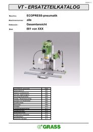
<strong>Unipress</strong> <strong>Vario</strong><br />
The star in your cabinet
Technical Data<br />
Dimensions:<br />
Width of machine tabel 740 mm<br />
Depth of machine tabel with bore distance 20 mm 410 mm<br />
Height of machine tabel 115 mm<br />
Depth of machine 850 mm<br />
Total height of machine<br />
Other data<br />
760 mm<br />
Press force of 0,6 MPa ( 6bar ) about 2800 N<br />
Weights:<br />
Total weight of the <strong>Unipress</strong> standard equipment 95 kg<br />
Total weight of the <strong>Unipress</strong>-<strong>Vario</strong> standard equipment 97 kg<br />
Electric Connections:<br />
Voltage according to the type plate ….. V<br />
Frequency according to the type plate ..… Hz<br />
Connection capacity of 3 phase motor 1,1 kW<br />
Connection capacity of 1 phase motor<br />
Power of the supply line according to the local codes & regulation<br />
1,5 kW<br />
Securing the supply line max. 1,5 x nominal current according to the type plate<br />
Pneumatic Connections:<br />
Dust, water and oil free air pressure at least 5,5 bar<br />
Max. allowable pressure in supply line: 10 bar<br />
Air pressure usage per jack-up drilling with 6 bar<br />
Air pressure usage per jack-up drilling<br />
1,25 l<br />
Suction intake force for compressor 7,5 l<br />
Other Connections:<br />
Dust collection: Connecting diameter Ø 80 mm<br />
Suction outlet force: about 2000 m3/h Emission values:<br />
Noise level in natural under 82 dB/A<br />
Noise level during drilling under 82 dB/A<br />
The star in your cabinet
The star in your cabinet<br />
Table of contents<br />
Page<br />
1. General Information 5 - 6<br />
1-001 List of illustration 5<br />
1-002 Manufacturer 6<br />
1-003 Copyright 6<br />
1-004 Guarantee Terms 6<br />
2. Safty Information 7 - 9<br />
2-001 Safty information 7<br />
2-002 Recommended usage 7<br />
2-003 Remaining risks 8<br />
2-004 Safty devices 8<br />
2-005 Danger- and safety measures 8<br />
2-006 Description of stickers 9<br />
3. Product Description 10 - 15<br />
3-001 Dust and noise emission ratings 10<br />
3-002 Usage 10<br />
3-003 Identification of products 10<br />
3-004 Variations 11<br />
3-005 Standard features 11<br />
3-006 Standard accessories 12-15<br />
4. Machine-Parts Description 16 - 33<br />
4-001 Overview of assembly group numbering 16-17<br />
4-002 Description of the individual assembly groups 18-21<br />
4-003 Gearbox - Variations - <strong>Unipress</strong> hole patterns 22-23<br />
4-004 Gearbox - Variations - <strong>Unipress</strong> <strong>Vario</strong> hole patterns 24-29<br />
4-005 Description of individual assembly operating elements 31<br />
4-006 Machine's function 31<br />
4-007 Description of the safty devices 31<br />
4-008 Pneumatic wiring diagram 30-31<br />
4-009 Electric wiring diagram 32-33<br />
5. Shipping and Installation of Machines 34<br />
5-001 Transport and storage requirements 34<br />
5-002 Space requirements 34<br />
5-003 Installation in designated space 34
Table of contents<br />
7-1 Requirements for operators<br />
7-2 Setting-up the <strong>Unipress</strong> 36-39<br />
7-201 Changing the gearbox on the <strong>Unipress</strong> 36-37<br />
7-202 Installing the drill fit into the rigid drill chucks on the <strong>Unipress</strong> 37<br />
7-203 Installing the drill fit into the quick change chuck on the <strong>Unipress</strong> 38-39<br />
7-204 Changing the quick change chuck on the <strong>Unipress</strong> 38-39<br />
7-3 Setting-up the <strong>Unipress</strong>-<strong>Vario</strong> 40-43<br />
7-301 Changing the gearbox on the <strong>Unipress</strong>-<strong>Vario</strong> 40-41<br />
7-302 Installing the drill fit into the quick change chuck on the <strong>Unipress</strong> <strong>Vario</strong> 43<br />
7-303 Changing the quick change chuck on the <strong>Unipress</strong> <strong>Vario</strong> 42-43<br />
7-4 Adjusting the <strong>Unipress</strong> and <strong>Unipress</strong> <strong>Vario</strong> 44-53<br />
7-401 Adjusting the material thickness (boring depth) 44-45<br />
7-402 Adjusting the boring distance 44-45<br />
7-403 Adjusting the boring speed 46-47<br />
7-404 Adjusting the side stops 46-47<br />
7-405 Working with the stop adjustment gauge 48-49<br />
7-406 Working with the index ruler 50-51<br />
7-407 Adjusting the hold down clamps 50-51<br />
7-408 Mounting the insertion die 52-53<br />
7-5 Examples of Usage 54-71<br />
7-501 Drilling and inserting the Grass Hinge System 1000/3000/4000 54-55<br />
7-502 Drilling and inserting the Grass Baseplate System 1000/3000 56-57<br />
7-503 Drilling the line boring patterns only with the <strong>Unipress</strong> <strong>Vario</strong> 58-59<br />
7-504 Drilling the cabinet member fastening bore holes only with the <strong>Unipress</strong> <strong>Vario</strong> 60-61<br />
7-505 Drilling the fronts for System 6000/7000 (with railing only with the <strong>Unipress</strong> <strong>Vario</strong>) 62-63<br />
7-506 Drilling the back panel for System 6000/7000 (with railing only with the <strong>Unipress</strong> <strong>Vario</strong>) 64-65<br />
7-507 Drilling for visible hinges 66-67<br />
7-508 Drilling and inserting of fastening hardware 68-69<br />
7-509 Drilling of handle borings only with the <strong>Unipress</strong>-<strong>Vario</strong> 70-71<br />
8. Trouble Shooting and Problem Solving 72-75<br />
8-001 Incorrect drilling distance - adjustment of scale 72-73<br />
8-002 Incorrect drilling depth - adjustment of scale 72-73<br />
8-003 Motor does not run 75<br />
8-004 Boring head does not descend 75<br />
8-005 Boring speed can't be adjusted 75<br />
8-006 Parts don't fit the drill patterns when inserted 74-75<br />
9. Maintenance and Care 76<br />
9-001 Maintenance plan 76<br />
9-002 Care information 76<br />
The star in your cabinet<br />
Page
1-001 List of Illustrations<br />
1. General Information<br />
Illustration Description Page<br />
4-001-01 Overview of machine with assembly group numbering 16<br />
4-002-01 Machine table assembly group 18<br />
4-002-02 Machine frame assembly group 18<br />
4-002-03 Motor support assembly group 20<br />
4-002-04 Open electrical switch cabinet 20<br />
4-002-05 Control panel with operating elements 20<br />
4-003-01 <strong>Unipress</strong> line boring pattern-belt driven gearbox 22<br />
4-003-02 <strong>Unipress</strong> belt driven gearbox 22<br />
4-003-03 <strong>Unipress</strong> line boring pattern-3 spindle gearbox 22<br />
4-003-04 <strong>Unipress</strong> 3 spindle gearbox 22<br />
4-003-05 <strong>Unipress</strong> <strong>Vario</strong> line boring pattern-belt driven gearbox 24<br />
4-003-06 <strong>Unipress</strong> <strong>Vario</strong> belt driven gearbox 24<br />
4-003-07 <strong>Unipress</strong> <strong>Vario</strong> line boring pattern-3 spindle gearbox 24<br />
4-003-08 <strong>Unipress</strong> <strong>Vario</strong> 3 spindle gearbox 24<br />
4-003-09 <strong>Unipress</strong> <strong>Vario</strong> line boring pattern hole gauge gearbox 26<br />
4-003-10 <strong>Unipress</strong> <strong>Vario</strong> line boring gearbox 26<br />
4-003-11 <strong>Unipress</strong> <strong>Vario</strong> boring pattern 8 spindle standard gearbox 26<br />
4-003-12 <strong>Unipress</strong> <strong>Vario</strong> 8 spindle standard gearbox 26<br />
4-003-13 <strong>Unipress</strong> <strong>Vario</strong> boring pattern 8 spindle special gearbox 28<br />
4-003-14 <strong>Unipress</strong> <strong>Vario</strong> 8 spindle special gearbox 28<br />
4-008-01 Pneumatic wiring diagram 30<br />
4-009-01 Electric wiring diagram 32<br />
5-001-01 Location of machine's center of gravity 34<br />
7-201-01/02/03 Changing of gearbox on the <strong>Unipress</strong> 36<br />
7-202-01 Installing drill bits in rigid drill chuck on the <strong>Unipress</strong> 36<br />
7-203-01 Installing drill bits in quick change drill chuck on the <strong>Unipress</strong> 38<br />
7-204-01 Changing the quick change drill chuck on the <strong>Unipress</strong> 38<br />
7-301-01/02/03 Removing a gearbox on the <strong>Unipress</strong> <strong>Vario</strong> 40<br />
7-301-04/05/06 Mounting a gearbox on the <strong>Unipress</strong> <strong>Vario</strong> 40<br />
7-302-01 Installing a drill bit in the quick change drill chuck on the <strong>Unipress</strong> <strong>Vario</strong> 42<br />
7-303-01/02 Changing the quick change drill chuck on the <strong>Unipress</strong> <strong>Vario</strong> 42<br />
7-401-01 Adjusting the material thickness 44<br />
7-402-01 Adjusting the boring distance 44<br />
7-403-01 Adjusting the operating speed 44<br />
7-404-01 Adjusting the side stops 44<br />
7-405-01/02 Operating the stop adjustment gauge 48<br />
7-406-01 Operating the index ruler 50<br />
7-407-01 Operating the holding clamps accessories 50<br />
7-408-01 Installing the insertion die 52<br />
7-501-01/02 Drilling and inserting Grass hinges 54<br />
7-502-01/02 Drilling and inserting Grass base plates 56<br />
7-503-01/02 Drilling line boring patterns 58<br />
7-504-01/02 Drilling bore hols for cabinet member fastening bore holes on <strong>Unipress</strong> <strong>Vario</strong> 60<br />
7-505-01/02 Drilling of front panels for Zargen System 6000/7000 62<br />
The star in your cabinet<br />
Page 5
1. General Information<br />
1-002 Manufacturer<br />
Grass AG Tel. 0043 / 05578 / 2211 - 0<br />
Bundesstr. 10 Fax 0043 / 05578 / 2211 - 59<br />
6973 Höchst<br />
Austria<br />
1-003 Copyright<br />
The manufacturer has the exclusive copyright. Any means of copying is permitted only<br />
with the permission of the manufacturer, unless the operating instructions are copied for<br />
the purpose of utilizing the machine.<br />
1-004 Terms of Guarantee<br />
The shipped <strong>Unipress</strong> or <strong>Unipress</strong><strong>Vario</strong> comes with a guarantee within the scope of<br />
"General Terms of Guarantees in the Association of the Machinery and Steel Construction Industry".<br />
In case of misuse, repairs by unauthorized or untrained personnel, usage of<br />
unauthorized replacement parts or accessories without written approval from the<br />
manufacturer invalidates any guarantee claims.<br />
We reserve technical modifications for whatever reason.<br />
When the machine is shipped from the manufacturing plant, it meets the latest regulation<br />
and technical standards.<br />
The manufacturer is under no obligation to modify machines free of charge due to changed specification.<br />
In case of guarantee claims, please contact the authorized Grass representative or an<br />
authorized Grass distributor.<br />
Lists of representatives or distributors are given in chapter 10-006.<br />
Guarantee claims will be honored only if the guarantee certificate was filled out completely<br />
and sent to the manufacturer.<br />
The guarantee or warranty include exclusive replacement of parts, but do not include installation<br />
parts, driving time, travel expenses, resulting damages, etc.<br />
Not included in the guarantee are:<br />
- transport damages (Postal service, railway, shipping reclaims)<br />
- natural wear and tear of parts<br />
- drill (bits)<br />
- damages resulting from negligence of protective rules<br />
- damages on the work material<br />
- loss of wages<br />
- reimbursement of down time<br />
- damages resulting from inappropriate handling or from misuse of the <strong>Unipress</strong>.<br />
Page 6 The star in your cabinet
2-001 Safety Information<br />
2. Safety Information<br />
Only authorized electricians or electrical specialists may work on the electrical<br />
equipment.<br />
The pneumatic and electric connecting lines are to be installed in an orderly manner and<br />
are to be protected from damage (for example, in cable channels or conduits, or something similar).<br />
The safety devices, which are included in this shipment, must always be utilized and shall not<br />
be by-passed or rendered inoperable.<br />
During service or maintenance work the machine must be turned off and blocked at<br />
the main electrical switch and to separate the machine from the pneumatic lines<br />
(for example, by quick coupling).<br />
Only tools which correspond in accordance with specifications and regulations (for<br />
example, from the Grass product line program) shall be utilized.<br />
Only hard metals, or HSS (high speed steel) drills with a total length of 57 mm and a<br />
shaft diameter of 10 mm may be utilized.<br />
The drill diameter may be a maximum of 35 mm on the drive spindle and a maximum<br />
of 12 mm O on all the other bore spindles.<br />
Shavings may not be blown off, but must be suctioned with the appropriate device.<br />
Machines shall always be turned off at the main switch when work is finished and<br />
secured so unauthorized persons cannot start them.<br />
Keep the workplace and surrounding area clean.<br />
Messiness and changing work places increase the risk of injury.<br />
Protect yourself from electrical shocks.<br />
Utilize the machine only in dry rooms and do not leave the machine outside in the rain.<br />
Keep unauthorized persons away from the machine.<br />
Only one person shall operate the machine.<br />
When working, keep your hands away from the working area of the drill and the<br />
insertion die arm.<br />
Wear appropriate work clothing when operating the machine.<br />
Use a hair net with long hair and do not wear wide or floppy pieces of clothing which<br />
could become caught in moving machine parts.<br />
2-002 Recommended Usage<br />
The Grass hinge drilling machine <strong>Unipress</strong>, as well as <strong>Unipress</strong> - <strong>Vario</strong>, is meant for<br />
drilling in solid wood and derived wood products. Other uses are not specified; thus,<br />
the manufacturer is not liable for resulting damages. The user alone assumes all risks.<br />
The user must conform to the operating instructions when determining appropriate<br />
usages.<br />
The machine shall only be operated, serviced and maintained by trained and<br />
authorized persons.<br />
The original set-up may not be modified.<br />
The star in your cabinet<br />
Page 7
2. Safety Information<br />
2-003 Remaining Risks<br />
The machine is built according to the present state of technology and known<br />
safety and technical directives. Still, risks remain for the life and health of the operator<br />
or of third parties, as well as damage to the machine and other material assets.<br />
Remaining risks consist of:<br />
- danger: even when the main switch is turned off the machine moves if the start<br />
button is activated<br />
- operation of the machine by unqualified personnel<br />
- operation of the machine without the required and recommended safety devices<br />
- inappropriate tooling or improper installation or attachment of tooling<br />
- the placement of the operator's second hand during drilling, inserting and installing<br />
movements of machine parts<br />
- additional people being in the area of the operating machine<br />
- contact with a turned-off machine which is not in order<br />
- not maintaining the machine's operation as is described in Chapter 7-0 "Operating<br />
the <strong>Unipress</strong> / <strong>Unipress</strong> - <strong>Vario</strong>".<br />
These remaining risks can be prevented by adhering to the information found in<br />
Chapters 2-0 and 7-0.<br />
2-004 Safety Devices<br />
Safety devices, information about dangers, etc. serve to ensure safety and may not, in<br />
any case be removed or be made inoperable.<br />
a) The main switch, which can be turned off to prevent unauthorized starting,<br />
should be turned off during adjustment and set-up processes.<br />
b) The pneumatic - filter - reducing regulator prevents the machine from<br />
overloading (see Chapter 4-006).<br />
c) For thermal overload protection of the motor see Chapter 4-007.<br />
d) Integrated dust collection to protect personnel from fine dust and simultaneously<br />
also conditionally protects one from injury by the drill.<br />
e) Motor first runs when the drill comes into contact with the work piece, and not<br />
with the pressing of the components<br />
2-005 How to prevent damages:<br />
Page 8<br />
Possible Damage Safety Measurements<br />
Drill chucks loosen Use snap-in drill chucks<br />
Drill breakage Use branded top quality drills such as Grass<br />
Drill-contact with machine parts Adjustment guide for drilling depth and distance<br />
The wooden board turns Use side stops and rear stops<br />
Feeding mechanism Not applicable<br />
The star in your cabinet
2. Safety Information<br />
Risk of Impact Not applicable, because the stroke motion is slow<br />
Drive The direct drive is fully enclosed in a gear casing.<br />
Installed drill bit is located behind the protection<br />
device (dust collection elements).<br />
Tool sets Stroke motion -- forward feed<br />
non self-locking buttons<br />
meet safety margins EN 294 depending on the risks<br />
Control System-- prevented by a switch with collars<br />
unexpected tool start mechanical motor safety EN 954-1 against dropping<br />
due to leakage in the pneumatic system<br />
Control System-- non self-locking buttons<br />
unexpected lifting disengagement<br />
Control System by the stop switch<br />
turn off the tool drive in the<br />
inoperative (idle) position<br />
Control System switch cam<br />
Press to begin tool start<br />
Noise (see appendix 2.1) measured emissions values correspond to the state<br />
of technology, work place emissions values are under<br />
85 dB (A)<br />
Dust (see appendix 2.2) The wood dust values fall below limits<br />
Warning:<br />
Electricity Stroke moting may also occur<br />
Equipped according to EN 60204, part 1, VDE 0110<br />
when motor is turned off<br />
as well as IEC 384<br />
2-006 Sticker Description<br />
The star in your cabinet<br />
Information sign for descent of vertical support<br />
Indicates EG conformity<br />
Prohibiting sign "Operation only by one person"<br />
Page 9
3. Product Description<br />
3-001 Dust and noise emissions ratings<br />
Noise<br />
The noise emissions according to EN31202 with CEN TC 142 in relation to the reported ISO 7960 noise emission determines<br />
the work place emissions ratings.<br />
LpA = 77.8 dB/A during drilling<br />
measuring uncertainties constants K are 4 dB/A<br />
Machine-specific adjustments:<br />
Drill bits: 1 Cup hole drill bit Ø 35 mm, depth 13 mm<br />
2 Dowelling drill bits Ø 8 mm, depth 13 mm<br />
Workpiece: chipboard<br />
Microphone position: 0,5 m in front of drilling motor axle<br />
Dust<br />
The determined dust rating according to DIN 33893 Part 2<br />
Static protected maximum amount (value) 0.49 mg / m3<br />
Interface exhaust connection piece:<br />
suction exhaust pipe: Ø 80 mm<br />
minimum air speed: 20 m/sec<br />
static suction: 932 Pa<br />
Suction elements:<br />
The machine's dust and shavings collection elements are arranged so that during correct operations<br />
(hook-up according to interface description) the amount of wood dust fall below the limit values.<br />
(Testing procedures for measurement are set forth in the DIN 33893 part 2).<br />
Connection of the suction system:<br />
The machine must be connected to a suction system according to the interface description.<br />
Hook-up lines are to be very inflammable.<br />
If an "electric" coupling is required for the suction system, the Grass company has as a special accessory -- a<br />
volume flow monitor with the appropriate contacts.<br />
3-002 Usage<br />
The <strong>Unipress</strong> / <strong>Unipress</strong> - <strong>Vario</strong> is designed exclusively for only those operations described in Chapter 2-001 and in<br />
Chapter 7-003 .<br />
Page 10 The star in your cabinet
3-004 Variations<br />
The <strong>Unipress</strong> is available in 2 different versions with various accessories.<br />
3. Product Description<br />
a) <strong>Unipress</strong> without gearbox, complete standard equipment, gear box to screw on as an<br />
accessory.<br />
Gear options:<br />
Gearbox for Grass hinges with dowel distance 42 / 11<br />
3 spindle gearbox for base plate in 32 mm intervals<br />
b) <strong>Unipress</strong> <strong>Vario</strong> with gearbox, complete standard equipment, with quick change device<br />
for gearbox, gearbox as an accessory<br />
Gearbox options:<br />
Gearbox for Grass hinges with dowel distance 42 / 11<br />
3 spindle gearbox for base plate in 32 mm intervals<br />
8 spindle gearbox special gearbox for Zarge front panel and cabinet members with<br />
50 mm distance<br />
11 spindle line boring in 32 mm evenly distanced notches with index ruler<br />
3-005 Standard Features<br />
<strong>Unipress</strong> or <strong>Unipress</strong> <strong>Vario</strong> completely installed consists of:<br />
-machine table, depth indicator over handwheel, adjustable over 0.2 mm intervals with<br />
a very legible scale<br />
-stabile durable machine frame with material thickness indicator, material thickness is<br />
adjustable by a very legible scale<br />
-motor support with E-motor (electric motor) and gear retainer (holding fixture)<br />
-insertion die arm which receives all insertion dies<br />
-complete electrical controls with a main switch that can be shut off, thermal motor<br />
voltage monitoring and 2 m of feeder cables<br />
-complete pneumatic control including service unit with adjustable operating speed, 2 m<br />
pneumatic lines, dust suction collection, adaptable to all gear variations<br />
-complete operating instructions<br />
-adjustment setting gauge L = 600 mm<br />
-tool kit, consisting of a forked open ended wrench 8 / 10, one of each Allen wrench<br />
keys 2,5/4/5/6, a marking gauge for hinges<br />
-fence 720 mm long with 2 left side stops, 2 right side stops from which one has a<br />
The star in your cabinet<br />
Page 11
3. Product Description<br />
<strong>Unipress</strong> - Gear box and drill chuck<br />
<strong>Unipress</strong> <strong>Vario</strong> - Gear box and drill chuck<br />
Page 12 The star in your cabinet
3-006 Standard Accessories<br />
For <strong>Unipress</strong> only<br />
3. Product Description<br />
Description Article Number:<br />
Gearbox for Grass hinge with dowel distance 42 / 11 mm 89611<br />
Drill chuck for the above gear box, screwed firmly to the gearbox 90519*<br />
Gearbox with 3 spindles for base lath (slat, strip-board, batten) and Zarge fronts 89613<br />
Quick change drill chuck for the above gearbox for drill Ø to 12 mm 37551*<br />
Quick change drill chuck for the above gearbox for drill Ø size 12 mm 35069<br />
All gearboxes screwed on with 2 Allen screws, each with a drill chuck each<br />
gearbox box spindle.<br />
For <strong>Unipress</strong> - <strong>Vario</strong> only<br />
Description<br />
Gearbox for Grass hinge with dowel distance 42 / 11 mm 91800<br />
Gearbox with 3 spindles for base lath (slat, strip-board, batten) and Zarge fronts 91801<br />
Gearbox with 11 spindles for hole pattern 91802<br />
Gearbox with 8 spindles for cabinet member fastener and Zarge fronts with railing 91803<br />
Gearbox with 8 spindles for Zarge fronts with 50 mm dowel distance and railing 91804<br />
Quick change drill chuck to the above gear box 91805<br />
All gearboxes with quick change device and each has a drill chuck, each gearbox<br />
spindle and a suitable canal for dust collection by ventilation.<br />
*as an accessory for additional necessary drills.<br />
The star in your cabinet<br />
Page 13
3. Product Description<br />
Side stop<br />
Page 14<br />
left right 10 mm right 13/15 mm<br />
Pendulum stop Stop pin Stop adjustment gauge<br />
Hold down device Insertion die for hinges Insertion die for base plate<br />
according to the style according to the style<br />
Drill bits Extension bar<br />
The star in your cabinet
3-006 Standard Accessories<br />
3. Product Description<br />
Description Article Number:<br />
Side stop left 89610<br />
Side stop, right 10 mm latch (standard) 89510<br />
Side stop, right 13 mm latch (for Zarge fronts 60../61../62../64..) 90520<br />
Side stop, right 15 mm latch (for Zarge fronts 77../78../79..) 92045<br />
Pendulum stop to drill back panels 90530<br />
Stop pin on guide ruler as stop bit gauge 90521<br />
Adjustment setting gauge L= 600 mm with 4 stop rings 39854<br />
Adjustment setting gauge L= 2000 mm with 5 stop rings 39855<br />
Set of pneumatic work piece hold down devices ( 2 pieces ) including control 91477<br />
1 piece extension bar style1 36-136 cm can be used left or right 37535<br />
1 piece extension bar style2 136-236 cm can be used left or right 37536<br />
Insert die for 1000/1003 steel cup 37554<br />
Insert die for 1000/1003 zinc cup 37555<br />
Insert die for 1006/3703 steel cup 90282<br />
Insert die for 1006/3703 zinc cup 30127<br />
Insert die for 1203/3903 zinc cup 37552<br />
Insert die for 1803 steel cup 37556<br />
Insert die for 950/954 39852<br />
Insert die for Twist-Lock Hinge, only bottom part 91285<br />
Insert die for Twist-Lock Hinge, comolete 91284<br />
Insert die for base plate G/DZK 1000 90266<br />
Insert die for base plate G/DZK 3000 90267<br />
Insert die for Häfele Rafix-fastener 90845<br />
Insert die for Hettich VB20 fastener 39467<br />
Insert die for Huwil fastener ...........<br />
Insert die for special products available upon request (special production) ...........<br />
Hard metal drill bit, shaft diameter Ø 10 mm, length 50 mm, bore diameter Ø 2,7 mm left 90887<br />
Hard metal drill bit, shaft diameter Ø 10 mm, length 50 mm, bore diameter Ø 2,7 mm right 93569<br />
Hard metal drill bit, shaft diameter Ø 10 mm, length 57 mm, bore diameter Ø 3 mm left 38135<br />
Hard metal drill bit, shaft diameter Ø 10 mm, length 57 mm, bore diameter Ø 3 mm right 38136<br />
Hard metal drill bit, shaft diameter Ø 10 mm, length 57 mm, bore diameter Ø 5 mm left 35809<br />
Hard metal drill bit, shaft diameter Ø 10 mm, length 57 mm, bore diameter Ø 5 mm right 35810<br />
Hard metal drill bit, shaft diameter Ø 10 mm, length 57 mm, bore diameter Ø 6 mm left 91572<br />
Hard metal drill bit, shaft diameter Ø 10 mm, length 57 mm, bore diameter Ø 6 mm right 91573<br />
Hard metal drill bit, shaft diameter Ø 10 mm, length 57 mm, bore diameter Ø 8 mm left 35811<br />
Hard metal drill bit, shaft diameter Ø 10 mm, length 57 mm, bore diameter Ø 8 mm right 35812<br />
Hard metal drill bit, shaft diameter Ø 10 mm, length 57 mm, bore diameter Ø 10 mm left 35813<br />
Hard metal drill bit, shaft diameter Ø 10 mm, length 57 mm, bore diameter Ø 10 mm right 35814<br />
Hard metal drill bit, shaft diameter Ø 10 mm, length 57 mm, bore diameter Ø 15 mm left 38178<br />
The star in your cabinet<br />
Page 15
4. Machine-Parts Description<br />
Illustration 4-001-01<br />
Page 16 The star in your cabinet
4. Machine-Parts Description<br />
4-001 Overview with Assembly Group Numbering Illustration 4-001-01<br />
1. Machine table with handwheel and dividing plate, fence and side stops. The pendulum<br />
stop is an accessory, as is the pneumatic work piece holder device.<br />
2. Machine frame<br />
3. Motor support with motor and insertion arm which receives the insertion die arm.<br />
4. Drill gearbox<br />
5. Electrical switch gear cabinet<br />
6. Control panel<br />
The star in your cabinet<br />
Page 17
4. Machine-Parts Description<br />
Illustration 4-002-01<br />
Illustration 4-002-02<br />
Page 18 The star in your cabinet
4-002 Description of the Individual Assembly Groups<br />
Machine Table Illustration 4-002-01<br />
4. Machine-Parts Description<br />
1. Table base<br />
2. Support fence 30/40 with plastic support<br />
3. Support fence 50/30 with plastic support<br />
4. Divider plate with 10 bore holes with interval space of 0.2 mm<br />
5. Handwheel with retractable pins 1 revolution = 2 mm<br />
6. Left side stop with 10 mm stop latch<br />
7. Right side stop with 10 mm stop latch<br />
8. Right side stop with 13 mm stop latch<br />
9. Fence<br />
10. Bit stop scale (bore distance)<br />
11. Legible markings<br />
12. Zero point for stop adjustment gauge<br />
13. Pendulum stop - Accessory<br />
14. Pneumatic clamp to hold down work piece<br />
Machine Frame Illustration 4-002-02<br />
1. Lateral right frame plate<br />
2. Upper frame plate<br />
3. Right cover<br />
4. Compressed air gauge 0.0 - 1.0 MPa (0-10bar=<br />
5. Regulating knob for compressed air adjustment. Life the knob to adjust. Turn<br />
clockwise to increase the pressure. After the adjustment press the regulating knob down.<br />
6. Guide bars for motor support<br />
7. Identification plate<br />
8. Material thickness scale<br />
9. Legible markings for material thickness<br />
10. Adjusting screws for material thickness with scale<br />
(Information aid: 1 turn = 1 mm, 1 graduation mark = 0.1 mm)<br />
The star in your cabinet<br />
Page 19
4. Machine-Parts Description<br />
Illustration 4-002-03<br />
Page 20 The star in your cabinet<br />
Illustration 4-002-04<br />
Illustration 4-002-05
4-002 Description of the Individual Assembly Groups<br />
Motor support Illustration 4-002-03<br />
4. Machine-Parts Description<br />
1. Motor support<br />
2. Motor<br />
3. Insertion die arm stop<br />
4. Insertion die arm<br />
5. Centering screw for lateral die position<br />
6. Handle<br />
7. Holding screw for insertion die arm with saucer spring<br />
8. Securing safety screw for holding screw<br />
9. Gearbox receptacle plate -- only with <strong>Unipress</strong> - <strong>Vario</strong><br />
10. Motor cover with identification description<br />
Electrical Switch gear Cabinet Illustration 4-002-04<br />
1. Electrical switch gear cabinet<br />
2. Reset button for thermal excess current release<br />
3. Roller limit switch<br />
4. Contactor K1<br />
5. Thermal excess current release<br />
6. Lead cable, coming from main switch Q1<br />
7. Cable for electric motor M1<br />
8. Cable for roller limit switch<br />
Electrical wiring diagram (see Chapter 4-009)<br />
Control Panel Illustration 4-002-05<br />
1. Main switch than can be shut off<br />
2. Rotary switch for pneumatic holding device<br />
3. Start button for drilling and insertion motion (5/2 type pneumatic valve)<br />
The star in your cabinet<br />
Page 21
4. Machine-Parts Description<br />
<strong>Unipress</strong> Drill gear box for hinges<br />
11 xx<br />
max Ø 35<br />
42<br />
xx = Adjustment range from 6 - 40 mm<br />
Illustration 4-003-01<br />
<strong>Unipress</strong> 3-spindle drill gear box<br />
xx<br />
32 32<br />
Illustration 4-003-03<br />
max Ø 15<br />
max Ø 35<br />
max Ø 15<br />
xx = Adjustment range from 6 - 170 mm<br />
max Ø 10<br />
Page 22 The star in your cabinet<br />
Illustration 4-003-02<br />
Illustration 4-003-04
4. Machine-Parts Description<br />
4-003 Gear box types - Variations - <strong>Unipress</strong> hole pattern<br />
Hinge gear box for <strong>Unipress</strong> Illustration 4-003-02<br />
1. Gear box coupling<br />
2. Gear box upper plate<br />
3. Gear box lower plate<br />
4. Gear box spindle<br />
5. Hold down pin with spring for dust collection canal<br />
6. Dust collection canal<br />
7. Drill chuck for drill bit with 10 mm O shaft<br />
Scope of application<br />
for all hinges from the Grass Product Line Series 1000, 3000 and 4000<br />
3 -spindle gear box for <strong>Unipress</strong> Illustration 4-003-04<br />
1. Gear box coupling<br />
2. Gear box upper plate<br />
3. Gear box lower plate<br />
4. Gear box spindle<br />
5. Hold down pin with spring for dust collection canal<br />
6. Dust collection canal<br />
7. Quick change drill chuck for drill bit with 10 mm O shaft<br />
Scope of applications:<br />
for all hinge from the Grass Product Line Series 4000<br />
for dowel base plates G/DZK Series 1000 and 3000<br />
for back panels Zarge System 6000 and 7000<br />
for front bore holes without railing for Grass Zarge System in 32 mm spaced intervals<br />
for various fastening hinges<br />
The star in your cabinet<br />
Page 23
4. Machine-Parts Description<br />
<strong>Unipress</strong>-<strong>Vario</strong> quick change drill gear box for hinges<br />
11 xx<br />
max Ø 35<br />
42<br />
xx = Adjustment range from 6 - 40 mm<br />
Illustration 4-003-05<br />
max Ø 10<br />
<strong>Unipress</strong>-<strong>Vario</strong> 3-spindle quick change drill gear box<br />
xx<br />
32 32<br />
Illustration 4-003-07<br />
max “ 15<br />
max “ 35<br />
max “ 15<br />
xx = Adjustment range from 6 - 170 mm<br />
Page 24 The star in your cabinet<br />
Illustration 4-003-06<br />
Illustration 4-003-08
4. Machine-Parts Description<br />
4-004 Gear box types - Variations - <strong>Unipress</strong> - <strong>Vario</strong> hole patterns<br />
<strong>Unipress</strong> - <strong>Vario</strong> quick change drill gear box for hinges Illustration 4-003-06<br />
1. Gear box coupling<br />
2. Holding pin<br />
3. Gear box locking pin<br />
4. Centering ring<br />
5. Gear box cover<br />
6. Gear box plate<br />
7. Gear box spindle<br />
8. Quick change drill chuck for drill with 10 mm shaft<br />
9. Hold down pin with spring for dust collection canal<br />
10. Dust collection canal<br />
11. Sticker label for bore distance and spindle rotation direction<br />
Red marking = counter clockwise rotating (red) drill<br />
Black marking = clockwise rotating (black) drill<br />
Scope of application:<br />
for all hinges from the Grass Product Line Series 1000, 3000 and 4000<br />
<strong>Unipress</strong> - <strong>Vario</strong> 3 spindle quick change drill gear box Illustration 4-003-08<br />
1. Gear box coupling<br />
2. Holding pin<br />
3. Gear box locking pin<br />
4. Centering ring<br />
5. Gear box cover<br />
6. Gear box plate<br />
7. Gear box spindle<br />
8. Quick change drill chuck for drill with 10 mm shaft<br />
9. Hold down pin with spring for dust collection canal<br />
10. Dust collection canal<br />
11. Sticker label for bore distance and spindle rotation direction<br />
Red marking = counter clockwise rotating (red) drill<br />
Black marking = clockwise rotating (black) drill<br />
Scope of applications:<br />
The star in your cabinet<br />
Page 25
4. Machine-Parts Description<br />
<strong>Unipress</strong> - <strong>Vario</strong> 11-spindle hole pattern quick change drill gear box<br />
xx<br />
max Ø 15 max Ø 15 max Ø 15 max Ø 15 max Ø 15 max Ø 15 max Ø 15 max Ø 15 max Ø 15 max Ø 15 max Ø 15<br />
xx<br />
32 32 32 32 32 32 32<br />
32 32 32 32 32 32 32 32 32 32<br />
Illustration 4-003-09<br />
<strong>Unipress</strong> - <strong>Vario</strong> 8- spindle quick change drill gear box<br />
max Ø 15<br />
max Ø 15<br />
max Ø 15<br />
max Ø 15<br />
max Ø 15<br />
max Ø 15<br />
max Ø 15<br />
max Ø 15<br />
xx = Adjustment range from 6 - 170 mm<br />
xx = Adjustment range from 6 - 170 mm<br />
Illustration 4-003-11<br />
Page 26 The star in your cabinet<br />
Illustration 4-003-10<br />
Illustration 4-003-12
4. Machine-Parts Description<br />
4-004 Gear box types - Variations - <strong>Unipress</strong> - <strong>Vario</strong> hole patterns<br />
<strong>Unipress</strong> - <strong>Vario</strong> 11-spindle hole pattern quick change drill gear box Illustration 4-003-10<br />
1. Gear box coupling<br />
2. Holding pin<br />
3. Gear box locking pin<br />
4. Centering ring<br />
5. Gear box cover<br />
6. Gear box plate<br />
7. Gear box spindle<br />
8. Quick change drill chuck for drill with 10 mm shaft<br />
9. Hold down pin with spring for dust collection canal<br />
10. Dust collection canal<br />
11. Sticker label for bore distance and spindle rotation direction<br />
Red marking = counter clockwise rotating (red) drill<br />
Black marking = clockwise rotating (black) drill<br />
Scope of application:<br />
for Line boring drills<br />
for pull and handle bore holes with the base under the work piece, or when both<br />
sides are bored<br />
<strong>Unipress</strong> - <strong>Vario</strong> 8- spindle quick change drill gear box Illustration 4-003-12<br />
1. Gear box coupling<br />
2. Holding pin<br />
3. Gear box locking pin<br />
4. Centering ring<br />
5. Gear box cover<br />
6. Gear box plate<br />
7. Gear box spindle<br />
8. Quick change drill chuck for drill with 10 mm shaft<br />
9. Hold down pin with spring for dust collection canal<br />
10. Dust collection canal<br />
11. Sticker label for bore distance and spindle rotation direction<br />
Red marking = counter clockwise rotating (red) drill<br />
Black marking = clockwise rotating (black) drill<br />
Scope of applications:<br />
for back panels Zarge System 6000 and 7000 with and without railing<br />
The star in your cabinet<br />
Page 27
4. Machine-Parts Description<br />
<strong>Unipress</strong> - <strong>Vario</strong> 8- spindle quick change drill gear box for special operations<br />
xx<br />
32 32 32 32 32 25 25<br />
max Ø 15<br />
max Ø 15<br />
max Ø 15<br />
max Ø 15<br />
max Ø 15<br />
max Ø 15<br />
max Ø 15<br />
max Ø 15<br />
xx = Adjustment range from 6 - 170 mm<br />
Illustration 4-003-13<br />
Page 28 The star in your cabinet<br />
Illustration 4-003-14
4. Machine-Parts Description<br />
4-004 Gear box types - Variations - <strong>Unipress</strong> - <strong>Vario</strong> hole patterns<br />
<strong>Unipress</strong> - <strong>Vario</strong> 8- spindle quick change drill gear box for special operations Illustration 4-003-14<br />
1. Gear box coupling<br />
2. Holding pin<br />
3. Gear box locking pin<br />
4. Centering ring<br />
5. Gear box cover<br />
6. Gear box plate<br />
7. Gear box spindle<br />
8. Quick change drill chuck for drill with 10 mm shaft<br />
9. Hold down pin with spring for dust collection canal<br />
10. Dust collection canal<br />
11. Sticker label for bore distance and spindle rotation direction<br />
Red marking = counter clockwise rotating (red) drill<br />
Black marking = clockwise rotating (black) drill<br />
Scope of applications:<br />
for back panels Zarge System 6000 and 7000 with and without railing<br />
for front bore holes for Grass Zarge System 6000 and 7000 with 50 mm dowel spacing<br />
for front fastening with and without railing in 32 mm spaced intervals<br />
The star in your cabinet<br />
Page 29
4. Machine-Parts Description<br />
Pneumatic wiring diagram<br />
max 10 bar<br />
Illustration 4-008-01<br />
7<br />
8<br />
10 10<br />
9<br />
2<br />
1<br />
1<br />
3<br />
Adjustment:<br />
5,5-6 bar<br />
0,55-0,6 MPa<br />
4 2<br />
5 1<br />
Page 30 The star in your cabinet<br />
2<br />
3<br />
3<br />
2<br />
1<br />
Alternative to 3<br />
3a<br />
21<br />
1 2<br />
2<br />
1<br />
5<br />
3<br />
4<br />
6
4-006 Machine's Function<br />
4. Machine-Parts Description<br />
-When the start button is activated, the motor begins. Releasing the start button activates an<br />
immediate return to the starting (normal) position.<br />
-The motor turns on about 20 mm before the drill touches the work piece.<br />
-The pneumatic guide switches over from a set speed to an adjustable work speed about 25 mm<br />
before the drill comes into contact with the work piece.<br />
-The motor does not run during insertion.<br />
-Pneumatic work piece holding clamp is tightened or released by a twist handle.<br />
4-007 Description of the Safety Devices<br />
-Thermal excess current release prevents overheating of the motor.<br />
-Mechanical blocks prevent the bore gear box from descending if the air pressure fails or falls.<br />
-The suction canal on the gear box prevents utilization of drills which are too large and also<br />
protects from injury by the drill.<br />
-Integrated dust suction collection together with the bore gear box prevents unacceptable dust<br />
emissions.<br />
-The main switch, which can be turned off, prevents unauthorized starts and ensure safety when<br />
setting up or doing maintenance work.<br />
-Dead man's control -- The machine operates only as long as the start button is activated.<br />
4-008 Pneumatic wiring diagram<br />
1 Hörbiger MKS-08H Filter - Pressure reducer 1/4" including compressed<br />
air gauge, pressure regulator and filter unit<br />
2 Camozzi DSV-358-895 5/2-type valve 1/8" with press button start valve for<br />
boring and insertion motion<br />
3 Bosch 0-820-402-102 2/2 type roller valve, reversing valve which adjusts to<br />
operating speed<br />
4 Hîöbiger DRV-1/8" One-way restrictor valve -- adjustable operating speed<br />
5 Stasto 1/8" Controllable reflux valve prevents the boring machine<br />
from descending if the pneumatic function suffers the<br />
loss of compressed air<br />
6 Camozzi 26N 2A 080 A 0125 Double action cylinder. Main cylinder moves the drilling<br />
machine<br />
7 Festo DFK-12-10-P Prevents the boring machine from descending during<br />
a compressed air outage. Mechanical operation first<br />
used from machine Nr. 94-07-614<br />
The star in your cabinet<br />
Page 31
4. Machine-Parts Description<br />
Electric wiring diagram<br />
J1<br />
3x380V/50Hz<br />
Illustration 4-009-01<br />
Electricity box<br />
11 MOBRF R11<br />
PE<br />
N<br />
L3<br />
L2<br />
L1<br />
K1<br />
Q1<br />
Page 32 The star in your cabinet<br />
a1<br />
a2<br />
F1<br />
M1<br />
L1<br />
T1<br />
L1<br />
T1<br />
L2<br />
T2<br />
L2<br />
T2<br />
L3<br />
T3<br />
L3<br />
T3<br />
T1 T2 T3<br />
U V W PE<br />
S2 P<br />
S1<br />
97 95<br />
98<br />
F2<br />
96
4-009 Electric Wiring Diagram Illustration 4-009-01<br />
4. Machine-Parts Description<br />
J1 GMSö 5 x 1.5 mm2 Lead cable<br />
Q1 Main switch, which can be shut off, prevents<br />
unauthorized start-ups<br />
K1* Lovato B9 380V Power protection switches on the main circuit<br />
F1* Lovato RC22 2.0-3.3A Thermal excess current release protects the motor<br />
from overheating when overloaded<br />
F2 Fuse for control circuit first on machines Nr. 94.12.xxx<br />
S1 Omron D4MC-2020 Roller limit switch<br />
switches on the power protection<br />
M1* Three-phase drive motor<br />
1* Lovato MBRF/11 Cable from roller limit switch S1, Electrical switchgear<br />
380V/50Hz 2.0-3.3A cabinet complete with screw fillings, power protection<br />
K1 and thermal excess current release F1<br />
2 YMM 3 x 1 mm2 Cable from electrical switchgear cabinet 1 to roller<br />
limit switch S1<br />
3 YMM 4 x 1.5 mm2 Cable from electrical switchgear cabinet 1 to motor M1<br />
4 GMSö 5 x 1.5mm2 Cable from main switch Q1 to electrical switchgear<br />
cabinet 1<br />
*All of these are dependent on the power supply and supply frequency of the country in which<br />
the machine is operated. The descriptive text is applicable to the electrical power<br />
3 x 380V / 50 Hz.<br />
The star in your cabinet<br />
Page 33
5. Shipping and Installation of Machines<br />
5-001 Transport<br />
The <strong>Unipress</strong> / <strong>Unipress</strong> - <strong>Vario</strong> shall be delivered on fastened on a pallet with a cardboard cover.<br />
Upon request, the <strong>Unipress</strong> can also be packed in a stabile wooden crate.<br />
Wood pallets and wooden crates can be transported without problems by a low lift platform<br />
truck or a fork lift truck.<br />
The machine must be protected during the transport and storage from moisture and wetness.<br />
Storage temperature should be between -20¯ and 50¯.<br />
Operating temperature should be between 10¯ and 40¯.<br />
Center of gravity<br />
5-002 Space Requirements<br />
The space requirement depends on the side of the work pieces.<br />
The minimal depth dimensions are about 200 cm.<br />
The minimal width dimensions are about 80 cm, and additionally 100 cm for each extension<br />
bar and side.<br />
The machine must be kept in a dry room away from moisture and wetness.<br />
The surrounding temperature of the operating machine should be between +10¯C to +40¯C.<br />
The relative humidity should not exceed 85% if at all possible.<br />
<strong>Vario</strong>us malfunctions with the machine may occur with large deviations in the environmental<br />
conditions.<br />
5-003 Installation in Designated Space<br />
The machine can be lifted on the machine table and on the machine frame.<br />
We recommend screwing the machine with the provided bore holes on the machine table on<br />
a base.<br />
Page 34 The star in your cabinet<br />
250<br />
340<br />
Illustration 5-001-01
6-001 Pneumatic connection<br />
The star in your cabinet<br />
6. Start-Up<br />
The machine has a 2 meter long air hose that has a diameter of 6/3. A Euro-Quick coupler plug<br />
is installed corresponding to the voltage in the country of destination. See Chapter 4-007 for the<br />
wiring diagram.<br />
a) Turn the regulator knob of the service unit counter clockwise.<br />
b) Connect the pneumatic air.<br />
The pneumatic air supply should only be accessible to maintenance personnel<br />
The quick coupling or a stop valve with ventilation shall be connected to the<br />
compressed air ductwork system.<br />
c) Turn the regulator knob clockwise until the pressure gauge pointer shows approximately<br />
0.55 - 0.6 MPa (0.55 - 0.6 bar).<br />
d) Conduct the function test without drilling bits and with the main switch off.<br />
When the start button is pressed, the motor descends. When the hand is removed<br />
from the start button, the machine must return immediately to the original position.<br />
e) Check the work piece holding clamps, if included (accessories).<br />
6-002 Electric connection<br />
The electric connection must be done by an authorized specialist and must meet local<br />
specifications.<br />
See Chapter 4-008 for the wiring diagram.<br />
The machine has a 2 meter long 5 -pole rubber cable. If necessary, according to the destination<br />
country, a 5-pole CEE 16A plug will be installed. If necessary, corresponding and available wall<br />
sockets are provided so the connection can be made by the customer.<br />
Start the machine as described in 6-001. Engage the main switch and press the start button<br />
(without the drill bits being connected) until the machine has reached its lowest point and the<br />
motor engages. Remove the hand from the start button and determine the rotation direction<br />
through the ventilation grid.<br />
Controlling the rotation direction: the rotation direction must conform to the arrow on the<br />
ventilation cover. A change in the rotation direction can only be performed by a specialist!<br />
6-003 Other connections<br />
Dust collection connection O 80 mm<br />
Required suction power about 2000 m h<br />
The <strong>Unipress</strong> must not be run without the dust collection system operating.<br />
See Chapter 3-001 "Dust and Noise Emissions Ratings".<br />
Page 35
7. Operating the <strong>Unipress</strong>/<strong>Unipress</strong><br />
Page 36 The star in your cabinet<br />
Illustration 7-201-01<br />
Illustration 7-201-02<br />
Illustration 7-201-03
7-1 Requirements for Operators<br />
7. Operating the <strong>Unipress</strong>/<strong>Unipress</strong><br />
The machine should be operated only by trained persons that are familiar with the machine's<br />
functions.<br />
This knowledge may be obtained by studying the operating instructions or by hands-on training<br />
by a specialist.<br />
It is the machine owner's responsibility to follow these instructions.<br />
7-2 Setting-up the <strong>Unipress</strong><br />
7-201 Changing the Gearbox on the <strong>Unipress</strong><br />
-Turn off the main switch.<br />
-Screw off the dust collection canal 1, according to the illustration 7-210-01 with the 17 mm<br />
forked open-end wrench.<br />
-Loosen both screws "2", according to the illustration 7-201-02 with the 6 mm Allen wrench.<br />
-Remove the gearbox.<br />
-Mount the new gearbox taking the gearbox coupling position into consideration. Illustration 7-201-03.<br />
-Tighten both screws "2".<br />
-Screw on the dust collection canal.<br />
7-202 Installing the Drill Bit into the Rigid Drill Chuck on the <strong>Unipress</strong><br />
-Turn off the main switch.<br />
-Loosen screw "1".<br />
-Insert the drill bit up to the stop, noting the position of the surface on the drill bit.<br />
-Tighten screw "1".<br />
The star in your cabinet<br />
Illustration 7-202<br />
Page 37
7. Operating the <strong>Unipress</strong>/<strong>Unipress</strong><br />
Illustration 7-203-01<br />
Illustration 7-204-01<br />
Page 38 The star in your cabinet<br />
X
7. Operating the <strong>Unipress</strong>/<strong>Unipress</strong><br />
7-203 Installing the Drill Bit into the Quick Change Chuck on the <strong>Unipress</strong> Illustration 7-203-01<br />
-Place the empty drill chuck on the drill setting gauge "3". Pull the tension ring "1" back<br />
from the drill chuck. Place the drill chuck on the gauge. Release the rings.<br />
-Loosen the locking screws "2".<br />
-Insert the drill bit completely, taking note of the surface of the drill shaft.<br />
-Tighten screw "2".<br />
-Remove the drill chuck from the gauge.<br />
Warning: All drill bits should be adjusted to an uniform dimension "X", so that the drill bits can<br />
be interchanged with each other.<br />
7-204 Changing the Quick Change Chuck on the <strong>Unipress</strong> Illustration 7-204-01<br />
-Turn off the main switch.<br />
-Place the drill chuck with the drill bit against the free gear box spindle.<br />
-Pull back the tension ring "1" according to Illustration 7-202-1<br />
-Press the drill chuck firmly against the spindle.<br />
-Release the tension ring.<br />
-Tighten both screws "2".<br />
-Turn the drill chuck until the drill chuck catches on the spindle and the tension ring is in the<br />
original position.<br />
The star in your cabinet<br />
Page 39
7. Operating the <strong>Unipress</strong>/<strong>Unipress</strong><br />
Illustration 7-301-01<br />
Illustration 7-301-02<br />
Illustration 7-301-03 Illustration 7-301-04<br />
Illustration 7-301-05 Illustration 7-301-06<br />
Page 40 The star in your cabinet
7. Operating the <strong>Unipress</strong>/<strong>Unipress</strong><br />
7-3 Setting-Up the <strong>Unipress</strong> - <strong>Vario</strong><br />
7-301 Changing the gearbox on the <strong>Unipress</strong> - <strong>Vario</strong><br />
a) Remove the gearbox Illustration 7-301-01 / 02 / 03<br />
-Turn off the main switch.<br />
-Hold the gearbox with both hands.<br />
-Press the pin "1" down.<br />
-Turn the gearbox about 15¯ counter clockwise to the stop.<br />
-Pull the gearbox downwardly.<br />
-Store the gearbox in a clean place, protected from dirt.<br />
b) Mounting a new gearbox Illustration 7-301-04 / 05 / 06<br />
-Turn off the main switch.<br />
-If necessary, clean the shavings and dust off the gearbox.<br />
-Pick up the gearbox correctly positioned with both hands.<br />
-Place the gearbox parallel against the motor support.<br />
-Turn about 15¯ counter clockwise in the bore hole of the receptacle plate.<br />
-Press the gearbox upward until the gearbox cover lies on the receptacle plate, and<br />
if necessary, secure the gearbox by rotating is so that the retaining pin agrees with the<br />
bore hole.<br />
-Turn the gearbox about 15¯ counter clockwise to the stop until the locking pin catches<br />
in the position bore hole.<br />
-When the locking pin catches, the gear box is ready for operation.<br />
The star in your cabinet<br />
Page 41
7. Operating the <strong>Unipress</strong>/<strong>Unipress</strong><br />
Illustration 7-303-01<br />
Illustration 7-303-02<br />
Page 42 The star in your cabinet
7. Operating the <strong>Unipress</strong>/<strong>Unipress</strong><br />
7-3 Setting-Up the <strong>Unipress</strong> - <strong>Vario</strong><br />
7-302 Installing the Drill Bit into the Quick Change Chuck on the <strong>Unipress</strong> - <strong>Vario</strong><br />
-Loosen fastening screw "1".<br />
-Insert the drill bit completely, taking note of the surface on the drill shaft.<br />
-Tighten screw "1" firmly.<br />
Warning: All drill bits should be adjusted to a uniform dimension "X", so that the drill bits can<br />
be interchanged with each other.<br />
Illustration 7-302-01<br />
7-302 Changing the Quick Change Chuck on the <strong>Unipress</strong> - <strong>Vario</strong><br />
a) Remove the drill chuck with the drill bit.<br />
-Turn off the main switch.<br />
-Turn the drill chuck about 5¯ left or right.<br />
-Pull the drill chuck down.<br />
b) Put up a new drill chuck with the drill bit Illustration 7-303-01 / 02<br />
-Turn off the main switch.<br />
-Place the drill chuck with drill bit against the gearbox spindle.<br />
-Note the markings on the gearbox:<br />
left (red) drill bit on the spindle with red markings<br />
right (black) drill bit on the spindle with black markings<br />
drive spindle always rotates clockwise (black drill bit)<br />
-Place the drill chuck on the spindle until resistance can be felt.<br />
-Rotate the drill chuck until the drill chuck slides up completely to the gearbox.<br />
Check: there should not be a gap of more than 2 mm between the drill chuck and the<br />
gearbox.<br />
The star in your cabinet<br />
X<br />
Page 43
7. Operating the <strong>Unipress</strong>/<strong>Unipress</strong><br />
Illustration 7-401-01<br />
Illustration 7-402-01<br />
Page 44 The star in your cabinet
7. Operating the <strong>Unipress</strong>/<strong>Unipress</strong><br />
7-4 Adjusting the <strong>Unipress</strong> and the <strong>Unipress</strong> - <strong>Vario</strong><br />
7-401 Adjusting the Material Thickness (Boring Depth) Illustration 7-401-01<br />
-Loosen the clamp screw "1".<br />
-Turn the adjusting screw "2" until the pointer "3" indicates the desired material thickness<br />
on the scale "4". (If the scale "4" is set during work adjustment,the bore hole results in adepth<br />
of 13 mm; the scale on the adjusting screw is only for better orientation while turning the screw).<br />
-Tighten the clamp screw.<br />
7-402 Adjusting the Boring Distance Illustration 7-402-01<br />
-Pull out the hinged handle "1" on the handwheel "2".<br />
-Turn to approximately 3 mm beyond the desired measurement shown on the scale "3".<br />
-Turn the handwheel right until the exact measurement is reached on the scale "3".<br />
-Move the hinged handle back until the bolt engages in the divider plate "4".<br />
IPlease note: The bore hole distance changes about 0.2 mm from bore hole to bore hole in<br />
the divider plate. One turn of the hand wheel is one space adjustment of exactly 2 mm.<br />
The star in your cabinet<br />
Page 45
7. Operating the <strong>Unipress</strong>/<strong>Unipress</strong><br />
Illustration 7-403-01<br />
Illustration 7-404-01<br />
Page 46 The star in your cabinet
7. Operating the <strong>Unipress</strong>/<strong>Unipress</strong><br />
7-4 Adjusting the <strong>Unipress</strong> and the <strong>Unipress</strong> - <strong>Vario</strong><br />
7-403 Adjusting the Boring Speed Illustration 7-403-01<br />
The machine has a constant feed speed and an adjustable working speed.<br />
The change-over point depends on the material thickness.<br />
By turning the adjusting screw counter clockwise, the working speed increases; by turning<br />
the screw clockwise, the working speed decreases.<br />
The working speed has to accommodate the tools and work pieces (materials).<br />
The harder the material of the work piece, the slower the working speed.<br />
The less the tool can cut, the slower the working speed.<br />
7-404 Adjusting the Side Stops Illustration 7-404-01<br />
-A required tool is the open fork wrench 8/10.<br />
-Loosen the screw "1" by turning the open fork wrench left.<br />
-Move the stop to the desired measurement.<br />
-Tighten the screw "1" by turning clockwise with an open fork wrench.<br />
The star in your cabinet<br />
Page 47
7. Operating the <strong>Unipress</strong>/<strong>Unipress</strong><br />
Illustration 7-405-01<br />
Illustration 7-405-02<br />
Page 48 The star in your cabinet
7. Operating the <strong>Unipress</strong>/<strong>Unipress</strong><br />
7-4 Adjusting the <strong>Unipress</strong> and the <strong>Unipress</strong> - <strong>Vario</strong><br />
7-405 Working with the Stop Adjustment Gauge Illustration 7-405-01/02<br />
-After adjusting side stops on the right side, the adjustment of the left side must be made<br />
(e.g., for right and left door at the hinge mounting).<br />
-Put the pin "A" of the stop adjustment gauge into the boring "1" of the center part "2".<br />
-Loosen the flap screw "B" of a collar "C".<br />
-Move the set collar "C" against the stop latch "3" of the side stop.<br />
-Tighten the flap screw "B" --Attention: Screw must point upward.<br />
-If necessary, adjust several set collars for several stops.<br />
-Push down on all stop latches on the right side.<br />
-Move the stop adjustment gauge by 180° to the left side.<br />
-Loosen a side stop on the left side and move it until the stop latch touches the set collar.<br />
Tighten the side stop.<br />
-If necessary, adjust several stops.<br />
If the same hole patterns are repeated, it is recommended to get a stop adjustment gauge for<br />
each hole pattern, and change the flap screws for pins.<br />
This allows for future exact side stop adjustment on both sides for a desired hole pattern.<br />
The star in your cabinet<br />
Page 49
7. Operating the <strong>Unipress</strong>/<strong>Unipress</strong><br />
Illustration 7-406-01<br />
Illustration 7-407-01<br />
Page 50 The star in your cabinet
7. Operating the <strong>Unipress</strong>/<strong>Unipress</strong><br />
7-4 Adjusting the <strong>Unipress</strong> and the <strong>Unipress</strong> - <strong>Vario</strong><br />
7-406 Working with the Index Ruler Illustration 7-406-01<br />
The index ruler is used only for line borings in order to adjust the distance between each stop.<br />
-Adjust the first stop to the desired distance.<br />
-Loose the second side stop.<br />
-Place the index ruler towards the edge "A1" of the stop latch of the first side stop.<br />
-Move the second stop (stop latch) towards the edge "A2" of the index ruler.<br />
-Tighten the side stop.<br />
-Proceed in the same way for several stops.<br />
-By adjust side stops in this manner, the distance between two boring rows is exactly 32 mm.<br />
To avoid adjustment errors, it is recommended to use a stop adjustment gauge for the<br />
second stop side.<br />
7-407 Adjusting the Hold Down Clamps Illustration 7-407-01<br />
The hold down clamp is an accessory and is suitable for material thicknesses up to 40 mm.<br />
-Loosen the two Allen screws on the backside of the hold down clamp with an Allen wrench<br />
5 mm.<br />
-Move the hold down clamp to the desired position.<br />
-Tighten both Allen screws.<br />
Please Note: There is a minimum distance between the hold down clamp and the motor<br />
support, as well as between the hold down clamp and the gearbox.<br />
Damage- and injury risks<br />
The star in your cabinet<br />
Page 51
7. Operating the <strong>Unipress</strong>/<strong>Unipress</strong><br />
Illustration 7-408-01<br />
Illustration 7-408-02<br />
Page 52 The star in your cabinet
7. Operating the <strong>Unipress</strong>/<strong>Unipress</strong><br />
7-4 Adjusting the <strong>Unipress</strong> and the <strong>Unipress</strong> - <strong>Vario</strong><br />
7-408 Mounting the Insertion Die Illustration 7-406-01/02<br />
-Swing the insertion die arm lightly to the front.<br />
-Loosen the clamp screw of the Insertion die.<br />
-Insert the die.<br />
-Tighten the clamp screw.<br />
The star in your cabinet<br />
Page 53
7. Operating the <strong>Unipress</strong>/<strong>Unipress</strong><br />
Illustration 7-501-01<br />
Illustration 7-501-02<br />
Page 54 The star in your cabinet
7-5 Examples of Usage<br />
7. Operating the <strong>Unipress</strong>/<strong>Unipress</strong><br />
7-501 Drilling and Inserting the Grass Hinge System 1000 / 3000 / 4000 Illustration 7-501-01/02<br />
Required Equipment:<br />
-Gearbox for hinges<br />
-(Gearbox for base plates - 3 spindle gearboxes for Twist-Lock-Hinges only)<br />
-1 drill bit right 35 mm Ø, shaft Ø 10 mm, length 57 mm<br />
-2 drill bit left 8 mm Ø, shaft Ø 10 mm, length 57 mm for hinges with dowels only<br />
-Insertion die, each according to the hinge style<br />
Machine Set-Up:<br />
-Gearbox change, if necessary, according to points 7-201 or 7-301 so that safety information<br />
is followed.<br />
-Changing the drill bit, if necessary, according to points 7-202 or 7-302 so that safety information<br />
is followed.<br />
-Adjust the material thickness according to point 7-401.<br />
-Adjust the boring distance according to the point 7-402 in the technical catalog.<br />
-Adjust the working speed, if necessary, according to the point 7-403.<br />
-Adjust the side stops according to points 7-404 and 7-405.<br />
-Adjust the pneumatic work piece hold down clamp, if provided and necessary, according to point 7-407.<br />
-Mount the insert die, if necessary, according to point 7-408.<br />
Operating the Machine:<br />
-Place the work piece on the machine table and press against the side stop and stops on the fence.<br />
-Press the start button until the drilling process is over.<br />
-Place the hinge on the insert die.<br />
-Swing the insertion die arm downward to the stop.<br />
-Press the start button until the hinge is completely inserted.<br />
Warning: Keep hands clear of the hold down clamp, the insertion die arm and the drill gearbox.<br />
The star in your cabinet<br />
Page 55
7. Operating the <strong>Unipress</strong>/<strong>Unipress</strong><br />
Illustration 7-502-01<br />
Illustration 7-502-02<br />
Page 56 The star in your cabinet
7-5 Examples of Usage<br />
7. Operating the <strong>Unipress</strong>/<strong>Unipress</strong><br />
7-502 Drilling and Inserting the Grass Base Plate System 1000 / 3000 Illustration 7-502-01/02<br />
Required Equipment:<br />
-Gearbox for base plates - 3-spindle gearbox<br />
-1 drill bit right 10 mm Ø, shaft Ø 10 mm, length 57 mm<br />
-1 drill bit left 10 mm Ø, shaft Ø 10 mm, length 57 mm<br />
-Insertion die, each according to the base plate style<br />
Machine Set-Up:<br />
-Gearbox change, if necessary, according to points 7-201 or 7-301 so that safety information<br />
is followed.<br />
-Changing the drill bit, if necessary, according to points 7-202 or 7-302 so that safety information<br />
is followed.<br />
-Adjust the material thickness according to point 7-401.<br />
-Adjust the boring distance according to the point 7-402 in the technical catalog.<br />
-Adjust the working speed, if necessary, according to the point 7-403.<br />
-Adjust the side stops according to points 7-404 and 7-405.<br />
-Adjust the pneumatic work piece hold down clamp, if provided and necessary, according to point 7-407.<br />
-Mount the insert die, if necessary, according to point 7-408.<br />
Operating the Machine:<br />
-Place the work piece on the machine table and press against the side stop and stops on the fence.<br />
-Press the start button until the drilling process is over.<br />
-Place the base plate on the insert die.<br />
-Swing the insertion die arm downward to the stop.<br />
-Press the start button until the base plate is completely inserted.<br />
Warning: Keep hands clear of the hold down clamp, the insertion die arm and the drill gearbox.<br />
The star in your cabinet<br />
Page 57
7. Operating the <strong>Unipress</strong>/<strong>Unipress</strong><br />
Illustration 7-503-01<br />
Illustration 7-503-02<br />
Page 58 The star in your cabinet
7-5 Examples of Usage<br />
7. Operating the <strong>Unipress</strong>/<strong>Unipress</strong><br />
7-503 Drilling the Line Boring Patterns only with the <strong>Unipress</strong> - <strong>Vario</strong> Illustration 7-503-01/02<br />
Required Equipment:<br />
-Gearbox for hole pattern - 11-spindle gearbox for <strong>Unipress</strong> - <strong>Vario</strong><br />
-6 drill bits right 5 (3) mm Ø, shaft Ø 10 mm, length 57 mm<br />
-5 drill bits left 5 (3) mm Ø, shaft Ø 10 mm, length 57 mm<br />
Machine Set-Up:<br />
-Gearbox change, if necessary, according to point 7-301 so that safety information<br />
is followed.<br />
-Changing the drill bit, if necessary, according to point or 7-302 so that safety information<br />
is followed.<br />
-Adjust the material thickness according to point 7-401.<br />
-Adjust the boring distance according to the point 7-402 in the technical catalog (as desired)<br />
-Adjust the working speed, if necessary, according to the point 7-403.<br />
-Adjust the side stops according to points 7-404 and 7-405 and 7-406.<br />
-Adjust the pneumatic work piece hold down clamp, if provided and necessary, according to point 7-407.<br />
Operating the Machine:<br />
-Place the work piece on the machine table and press against the side stop and stops on the fence.<br />
-Press the start button until the drilling process is over.<br />
Warning: Keep hands clear of the hold down clamp and the drill gearbox.<br />
The star in your cabinet<br />
Page 59
7. Operating the <strong>Unipress</strong>/<strong>Unipress</strong><br />
Illustration 7-504-01<br />
Illustration 7-504-02<br />
Page 60 The star in your cabinet
7-5 Examples of Usage<br />
7. Operating the <strong>Unipress</strong>/<strong>Unipress</strong><br />
7-504 Drilling the Cabinet Member Fastening Bore Holes only with the <strong>Unipress</strong> - <strong>Vario</strong><br />
Illustration 7-503-01/02<br />
Required Equipment:<br />
-Gearbox for cabinet members - 8-spindle gearbox - Standard<br />
-1 drill bit right 10 mm Ø, shaft Ø 10 mm, length 57 mm<br />
-1 drill bit left 10 mm Ø, shaft Ø 10 mm, length 57 mm<br />
Machine Set-Up:<br />
-Gearbox change, if necessary, according to point 7-301 so that safety information<br />
is followed.<br />
-Changing the drill bit, if necessary, according to point 7-302 so that safety information<br />
is followed.<br />
-Adjust the material thickness according to point 7-401.<br />
-Adjust the boring distance according to the point 7-402 in the technical catalog<br />
-Adjust the working speed, if necessary, according to the point 7-403.<br />
-Adjust the side stops according to points 7-404 and 7-405.<br />
-Adjust the pneumatic work piece hold down clamp, if provided and necessary, according to point 7-407.<br />
Operating the Machine:<br />
-Place the work piece on the machine table and press against the side stop and stops on the fence.<br />
-Press the start button until the drilling process is over.<br />
The star in your cabinet<br />
Page 61
7. Operating the <strong>Unipress</strong>/<strong>Unipress</strong><br />
Illustration 7-505-01<br />
Illustration 7-505-02<br />
Page 62 The star in your cabinet
7-5 Examples of Usage<br />
7. Operating the <strong>Unipress</strong>/<strong>Unipress</strong><br />
7-505 Drilling the Fronts for System 6000 / 7000 with Railing Only with the <strong>Unipress</strong> - <strong>Vario</strong><br />
Illustration 7-505-01/02<br />
Required Equipment:<br />
-3-spindle gearbox<br />
-Gearbox for cabinet members - 8-spindle gearbox - Standard<br />
-Gearbox for Zarge fronts with 50 mm dowel distance, if necessary<br />
-2 (1) drill bit right 10 mm Ø, shaft Ø 10 mm, length 57 mm<br />
-(1) drill bit left 10 mm Ø, shaft Ø 10 mm, length 57 mm<br />
-Clamp equivalents for 32 mm dowel distance<br />
Machine Set-Up:<br />
-Gearbox change, if necessary, according to point 7-301 so that safety information<br />
is followed.<br />
-Changing the drill bit, if necessary, according to point 7-302 so that safety information<br />
is followed.<br />
-Adjust the material thickness according to point 7-401.<br />
-Adjust the boring distance according to the point 7-402 in the technical catalog<br />
-Adjust the working speed, if necessary, according to the point 7-403.<br />
-Adjust the side stops according to points 7-404.<br />
-Adjust the pneumatic work piece hold down clamp, if provided and necessary, according to point 7-407.<br />
Operating the Machine:<br />
-Place the work piece on the machine table and press against the side stop and stops on the fence.<br />
-Press the start button until the drilling process is over.<br />
Warning: Keep hands clear of the hold down clamp and the drill gearbox.<br />
The star in your cabinet<br />
Page 63
7. Operating the <strong>Unipress</strong>/<strong>Unipress</strong><br />
Illustration 7-506-01<br />
Illustration 7-506-02<br />
Page 64 The star in your cabinet
7-5 Examples of Usage<br />
7. Operating the <strong>Unipress</strong>/<strong>Unipress</strong><br />
7-506 Drilling the Back Panels for System 6000 / 7000 with Railing Only with the <strong>Unipress</strong> - <strong>Vario</strong><br />
Illustration 7-506-01/02<br />
Required Equipment:<br />
-Gearbox with at least one spindle (without railing)<br />
-(3-spindle gearbox)<br />
-(Gearbox for cabinet members - 8-spindle gearbox - Standard)<br />
-(Gearbox for Zarge fronts with 50 mm dowel distance, if necessary)<br />
-Pendulum stop<br />
-1 drill bit right 10 mm Ø, shaft Ø 10 mm, length 57 mm<br />
-(1) drill bit left 10 mm Ø, shaft Ø 10 mm, length 57 mm<br />
-Clamp equivalency if a railing is also bored.<br />
Machine Set-Up:<br />
-Gearbox change, if necessary, according to point 7-301 so that safety information<br />
is followed.<br />
-Changing the drill bit, if necessary, according to point 7-302 so that safety information<br />
is followed.<br />
-Adjust the material thickness according to point 7-401.<br />
-Adjust the boring distance according to the point 7-402 in the technical catalog<br />
-Adjust the working speed, if necessary, according to the point 7-403.<br />
-Adjust the side stops according to points 7-404.<br />
-Adjust the pneumatic work piece hold down clamp, if provided and necessary, according to point 7-407.<br />
Operating the Machine:<br />
-Place the work piece on the machine table and press against the side stop and stops on the fence.<br />
-Press the start button until the drilling process is over.<br />
Warning: Keep hands clear of the hold down clamp and the drill gearbox.<br />
The star in your cabinet<br />
Page 65
7. Operating the <strong>Unipress</strong>/<strong>Unipress</strong><br />
Illustration 7-507-01<br />
Illustration 7-507-02<br />
Page 66 The star in your cabinet
7-5 Examples of Usage<br />
7. Operating the <strong>Unipress</strong>/<strong>Unipress</strong><br />
7-507 Drilling of Visible Hinges Illustration 7-507-01/02<br />
Required Equipment:<br />
-Gearbox for hinges -(Gearbox for Zarge fronts with 50 mm dowel distance, if necessary)<br />
-1 drill bit right 35 mm Ø, shaft Ø 10 mm, length 57 mm<br />
-2 drill bits left 8 mm Ø, shaft Ø 10 mm, length 57 mm<br />
-Insertion die according to the hinge type<br />
Machine Set-Up:<br />
-Gearbox change, if necessary, according to point 7-201 or 7-301 so that safety information<br />
is followed.<br />
-Changing the drill bit, if necessary, according to point 7-202 or 7-302 so that safety information<br />
is followed.<br />
-Adjust the material thickness according to point 7-401.<br />
-Adjust the boring distance according to the point 7-402 in the technical catalog<br />
-Adjust the working speed, if necessary, according to the point 7-403.<br />
-Adjust the side stops according to points 7-404 and 7-405.<br />
-Adjust the pneumatic work piece hold down clamp, if provided and necessary, according to point 7-407.<br />
-Mount the insertion die, if necessary, according to point 7-408.<br />
Operating the Machine:<br />
-Place the work piece on the machine table and press against the side stop and stops on the fence.<br />
-Press the start button until the drilling process is over.<br />
-Press the hinge on the insertion die.<br />
-Swing the insertion die arm downward to the stop.<br />
-Press the start button until the hinge is completely inserted.<br />
The star in your cabinet<br />
Page 67
7. Operating the <strong>Unipress</strong>/<strong>Unipress</strong><br />
Illustration 7-508-01<br />
Illustration 7-508-02<br />
Page 68 The star in your cabinet
7-5 Examples of Usage<br />
7. Operating the <strong>Unipress</strong>/<strong>Unipress</strong><br />
7-508 Drilling and Inserting of Fastening Hardware Illustration 7-508-01/02<br />
Required Equipment:<br />
-Gearbox for base plates -3-spindle gearbox<br />
-1 drill bit right 20 mm Ø ( or other Ø) , shaft Ø 10 mm, length 57 mm<br />
-2 drill bits left 10 mm Ø, shaft Ø 10 mm, length 57 mm<br />
-Insertion die according to the fastening hardware<br />
Machine Set-Up:<br />
-Gearbox change, if necessary, according to point 7-201 or 7-301 so that safety information<br />
is followed.<br />
-Changing the drill bit, if necessary, according to point 7-202 or 7-302 so that safety information<br />
is followed.<br />
-Adjust the material thickness according to point 7-401.<br />
-Adjust the boring distance according to the point 7-402 in the technical catalog<br />
-Adjust the working speed, if necessary, according to the point 7-403.<br />
-Adjust the side stops according to points 7-404 and 7-405.<br />
-Adjust the pneumatic work piece hold down clamp, if provided and necessary, according to point 7-407.<br />
-Mount the insertion die, if necessary, according to point 7-408.<br />
Operating the Machine:<br />
-Place the work piece on the machine table and press against the side stop and stops on the fence.<br />
-Press the start button until the drilling process is over.<br />
-Press the hinge on the insertion die.<br />
-Swing the insertion die arm downward to the stop.<br />
-Press the start button until the hinge is completely inserted.<br />
Warning: Keep hands clear of the hold down clamp, insertion die arm and the drill gearbox.<br />
The star in your cabinet<br />
Page 69
7. Operating the <strong>Unipress</strong>/<strong>Unipress</strong><br />
Illustration 7-509-01<br />
Illustration 7-509-02<br />
Page 70 The star in your cabinet
7-5 Examples of Usage<br />
7. Operating the <strong>Unipress</strong>/<strong>Unipress</strong><br />
7-509 Drilling of Handle Borings Only with the <strong>Unipress</strong> - <strong>Vario</strong> Illustration 7-509-01/02<br />
Required Equipment:<br />
-Gearbox for cabinet members -8-spindle gearbox - Standard<br />
-Gearbox for line boring - 11-spindle gearbox<br />
-1 drill bit right 5 mm Ø ( or other Ø) , shaft Ø 10 mm, length 57 mm<br />
-2 drill bits left 5 mm Ø, shaft Ø 10 mm, length 57 mm<br />
-a base with a thickness of at least 5 mm so that the work piece can be bored through<br />
Machine Set-Up:<br />
-Gearbox change, if necessary, according to point 7-201 or 7-301 so that safety information<br />
is followed.<br />
-Changing the drill bit, if necessary, according to point 7-202 or 7-302 so that safety information<br />
is followed.<br />
-Adjust the material thickness to 10 mm so it can be bored through. Work pieces that are<br />
thicker than 25 mm without a base can be drilled on both sides.<br />
-Adjust the boring distance as desired.<br />
-Adjust the working speed, if necessary, according to the point 7-403.<br />
-Adjust the side stops according to points 7-404 and 7-405.<br />
-Adjust the pneumatic work piece hold down clamp, if provided and necessary, according to point 7-407.<br />
Operating the Machine:<br />
-Place the work piece on the machine table and press against the side stop and stops on the fence.<br />
-Press the start button until the drilling process is over.<br />
Warning: Keep hands clear of the hold down clamp, insertion die arm and the drill gearbox.<br />
The star in your cabinet<br />
Page 71
8. Trouble Shooting and Problem Solving<br />
Illustration 8-001-01<br />
Illustration 8-002-01<br />
Page 72 The star in your cabinet
8. Trouble Shooting and Problem Solving<br />
8-001 Incorrect Drilling Distance - Adjustment of Scale Illustration 8-001-01<br />
-Mount gearbox, if necessary, according to point 7-201 or 7-301.<br />
-Mount a drill bit, if necessary, according to point 7-202 or 7-302.<br />
-Follow safety information and guidelines.<br />
-Place a sample work piece.<br />
-Press against the depth stops on fence.<br />
-Drill one hole.<br />
-Measure drilling distance and compare with the set number on the scale.<br />
-If the numbers are not identical, loosen both screws "1" with 4 mm Allen wrench, move the<br />
measuring scale to measured number, then tighten both screws "1".<br />
-Repeat drilling cycle and compare boring distance again with the number on the scale.<br />
8-002 Incorrect Drilling Depth - Adjustment of Scale Illustration 8-002-01<br />
-Place the sample material on machine table.<br />
-Loosen clamp screw "1".<br />
-Adjust material thickness according to point 7-401.<br />
-Lift the adjustment screw "2", then place the material "3" , which is as thick as the desired<br />
drilling depth, underneath.<br />
-Drill a sample cycle. In this position the drill bit cutters should just drill the material (leaving<br />
obvious marks on the material).<br />
-If the drilling is too deep, the adjustment screw must be turned clockwise (1 turn = 1 mm).<br />
-If the drill cutters do not reach the material surface, adjustment screw "2" must be turned<br />
counter clockwise.<br />
-Repeat sample drilling and corrections until the drill cutters drill the material correctly.<br />
-Remove the work material "3". The material thickness, according to scale "4", must agree with<br />
the actual material thickness.<br />
-In case of discrepancies, loosen both screws "5" with 2.5 mm Allen wrench. Move the<br />
measuring scale until the measured material thickness is identical with the material thickness<br />
shown on scale "4". Tighten both screws "5".<br />
The star in your cabinet<br />
Page 73
8. Trouble Shooting and Problem Solving<br />
Illustration 8-006-01<br />
Illustration 8-006-02<br />
Page 74 The star in your cabinet
8. Trouble Shooting and Problem Solving<br />
8-003 Motor Does Not Run<br />
a) Turn on the main switch on the control panel<br />
b) If the thermal overload safety feature kicks in, press the blue button on the switch gear<br />
cabinet on the back of the machine.<br />
c) Check to see if the machine is plugged in.<br />
d) Check the fuses in the in-house distributing panel, and if necessary, change the fuse.<br />
e) If points a through d are unsuccessful, then consult a specialist . See wiring<br />
diagram in chapter 4-008.<br />
8-004 Boring Head Does Not Descend<br />
a) Check the air pressure in the machine. The pressure gauge should indicate<br />
0.55 - 0,6 MPa (5.5 - 6 bar).<br />
b) If the motor support with the gearbox stops shortly before reaching the work piece,<br />
adjust the choke screw as described in point 7-403.<br />
c) If points a through d are unsuccessful, then consult a specialist. See wiring diagram<br />
in chapter 4-007.<br />
8-005 Boring Speed Cannot Be Adjusted<br />
If the boring speed cannot be adjusted as described in chapter 7-403, a specialist must be<br />
consulted. Wiring diagram chapter 4-007.<br />
8-006 Parts Do Not Fit The Drill Patterns When Inserted<br />
-Drill a hole pattern. Mount the insertion die. Mount the part that is to be inserted. Move the<br />
insertion frame down. Adjust the pressurized air on the pressure reducing gauge to<br />
approximately 0.2 MPa. Insert.<br />
-If the part does not fit the drill pattern:<br />
a) If the part is too far to the right or left Illustration 8-006-01<br />
-Loosen the screw "1" with a 4 mm Allen wrench. Move the die left or right. Tighten<br />
the screw again.<br />
b) If the part is too close to the fence. Illustration 8-006-02<br />
Loosen both hexagon nuts "2" with an open forked 8/10 wrench. Screw out the Allen<br />
head screws "3" with 4 or 5 mm Allen wrench in a counter clockwise direction. Then<br />
tighten the nuts "2" again.<br />
c) If the part is too close to the fence. Illustration 8-006-02<br />
Loosen both hexagon nuts "2" with an open forked 8/10 wrench. Screw out the Allen<br />
head screws "3" with a 4 or 5 mm Allen wrench in a counter clockwise direction. Then<br />
tighten the nuts "2" again.<br />
The star in your cabinet<br />
Page 75
9. Maintenance and Care<br />
9-001 Maintenance Plan<br />
Maintenance work should only be done when the main switch is turned off and the pneumatic air<br />
has been disconnected.<br />
Daily:<br />
After the end of work, the machine should be secured against being started by unauthorized<br />
personnel.<br />
Weekly, or as necessary:<br />
Drain the filter-pressure reducer; disconnect the machine from the pneumatic air cable for this.<br />
(The filter-pressure reducer is equipped with a semi-automatic drain).<br />
Monthly:<br />
Clean the drill distance adjustment spindle and lubricate the spindle with commercial grease.<br />
Check the drill distance with sample drilling; correct, if necessary, according to point 8-001.<br />
Check the drilling depth - material thickness with sample drilling. Correct, if necessary,<br />
according to 8-002.<br />
Check the function of the side stops.<br />
Check the position of the insertion dies, and if necessary, correct according to point 8-006.<br />
Yearly:<br />
In order to keep the machine running smoothly for many years, it is recommended to have<br />
the machine serviced by a Grass Maintenance Technician or by a Grass Distributor every<br />
1 to 3 years.<br />
9-002 Care Information<br />
The machine should be cleaned only after the main switch is turned off and the pneumatic<br />
air is disconnected.<br />
The machine should be cleaned as needed. This includes vacuuming of wood shavings.<br />
Clean with a dry cloth and do not use caustic cleaners such as gasoline, nitro diluted solutions,<br />
Page 76 The star in your cabinet
10-001 Guarantee Certificate<br />
The star in your cabinet<br />
10. Miscellaneous<br />
Buyer: Name...................................................<br />
Street................................................... Zip code....................................<br />
City...................................................... Country......................................<br />
Telephone............................................ Fax............................................<br />
Dealer: Name...................................................<br />
Street................................................... Zip code....................................<br />
City...................................................... Country......................................<br />
Date of purchase:<br />
Machine: *Please underline the appropriate<br />
Style:...................................................<br />
Machine number:........................................<br />
Voltage / Frequency according to the identification plate:.........................................<br />
Gearbox for <strong>Unipress</strong> with fixed screws on gearbox<br />
Gearbox for hinges* 3-spindle gearbox*<br />
Gearbox for <strong>Unipress</strong> - <strong>Vario</strong> with changeable gearbox<br />
Gearbox for hinges* 3-spindle gearbox*<br />
8-spindle gearbox 8-spindle gearbox with special distance of 50 mm*<br />
11-spindle gearbox for line boring system,*<br />
General:<br />
The delivered <strong>Unipress</strong> is guaranteed is accordance with the general guarantee terms of the<br />
Association of the Machine and Steel Construction Industry. Any warranty claims are voided in<br />
cases of misuse, unauthorized repairs, use of non-Grass or unauthorized spare parts, as well<br />
as use of non-Grass or unauthorized accessories. We reserve the right to make technical<br />
modifications for whatever reasons. When the machine is shipped from the manufacturing<br />
plant, it meets the latest standards of requirements and technical standards. The manufacturer<br />
is not obligated to modify for free of charge any machines which were previously delivered to<br />
meet changed specifications.<br />
Without a completed guarantee form sent to the manufacturer, there are not guarantee claims<br />
at all.<br />
The buyer agrees to store this data in an electronic data processing system.<br />
Page 77
An<br />
Firma Grass GmbH<br />
Grass Platz 1<br />
A-6973 Höchst/Austria<br />
From<br />
Page 78 The star in your cabinet
10-002 Disposal Form<br />
The star in your cabinet<br />
10. Miscellaneous<br />
Buyer: Name...................................................<br />
Street................................................... Zip code....................................<br />
City...................................................... Country......................................<br />
Telephone............................................ Fax............................................<br />
Machine: *Please underline the appropriate<br />
Style:...................................................<br />
Machine number:........................................<br />
Voltage / Frequency according to the identification plate:.........................................<br />
Gearbox for <strong>Unipress</strong> with fixed screws on gearbox<br />
Gearbox for hinges* 3-spindle gearbox*<br />
Gearbox for <strong>Unipress</strong> - <strong>Vario</strong> with changeable gearbox<br />
Gearbox for hinges* 3-spindle gearbox*<br />
8-spindle gearbox 8-spindle gearbox with special distance of 50 mm*<br />
11-spindle gearbox for line boring system,*<br />
General:<br />
The buyer hereby confirms that the machine has been disposed of properly. The machine<br />
consists of the following materials:<br />
steel / iron parts<br />
machine frame, motor support, machine table, various parts of the gearbox<br />
aluminum<br />
parts of the side stops, gearbox casing, all extension bars<br />
PVC:<br />
green support strips on the machine table<br />
various plastics:<br />
cover caps for machine table protrusions, pneumatic hoses<br />
The following parts cannot be associated with any material group:<br />
electrical equipment, pneumatic parts<br />
Page 79
An<br />
Firma Grass GmbH<br />
Grass Platz 1<br />
A-6973 Höchst/Austria<br />
From<br />
Page 80 The star in your cabinet
10-003 Resale From<br />
Seller:<br />
The star in your cabinet<br />
10. Miscellaneous<br />
Name:.............................................<br />
Street.............................................. Zip code:..........................................<br />
City:........................................…..… Country:............................................<br />
Telephone:...................................... Fax:...................................................<br />
Reason for slling machine:<br />
Buyer:<br />
Name:.............................................<br />
Street.............................................. Zip code:................................….…..<br />
City:.........................................…… Country:............................................<br />
Telephone:...................................... Fax:...................................................<br />
After reslling the machine, please return the completed from to the manufacturer.<br />
The buyer agrees to store the data in an electronic data processing system.<br />
Page 81
An<br />
Firma Grass GmbH<br />
Grass Platz 1<br />
A-6973 Höchst/Austria<br />
From<br />
Page 82 The star in your cabinet
10-004 Questionnaire 1: Reason for Purchase<br />
The star in your cabinet<br />
10. Miscellaneous<br />
Buyer: Name...................................................<br />
Street................................................... Zip code....................................<br />
City...................................................... Country......................................<br />
Telephone............................................ Fax............................................<br />
Size of company: .................................... number of personnel<br />
Machine is being used in the area of:* *please check the appropriate<br />
kitchen cabinet manufacturing<br />
general interior design and engineering<br />
general furniture fabrication<br />
Application of machine:<br />
Drill hinge Insertion of hinges<br />
Drill dowel base plates Insertion of dowel base plates<br />
Drill fastening hardware Insertion of fastening hardware<br />
Drill catch base plates<br />
Drill cabinet member slides<br />
Drill line boring system<br />
Drill fronts for Zarge<br />
Drill back panel for Zarge<br />
Drill handle borings in front panels<br />
Other applications, please indicate........................................<br />
Operating time of the machine:*<br />
about ................hours per month<br />
What was the reason for choosing <strong>Unipress</strong> over the competitors' machines?<br />
cost versatility of machine<br />
appearance wide range of accessories<br />
quality loyal Grass customer<br />
cost / performance ratio Grass processor<br />
durability of the machine<br />
How did you find out about the <strong>Unipress</strong>?*<br />
Magazine advertisement<br />
Visiting a show<br />
distributor showroom<br />
distributor visit<br />
Page 83
An<br />
Firma Grass GmbH<br />
Grass Platz 1<br />
A-6973 Höchst/Austria<br />
From<br />
Page 84 The star in your cabinet
10-005 Questionnaire 2: Satisfaction<br />
Buyer: Name...................................................<br />
Street................................................... Zip code....................................<br />
City...................................................... Country......................................<br />
Telephone............................................ Fax............................................<br />
How do you rate your satisfaction with the machine?*<br />
very good fair<br />
good not at all<br />
Would you buy the machine again?*<br />
yes no because the machine meets the requirements<br />
yes no because there are better machines available<br />
yes no because my usage needs have changed<br />
yes no because of price<br />
yes no because of the economic situation<br />
yes no because...........................................................<br />
yes no because...........................................................<br />
yes no because...........................................................<br />
yes no because...........................................................<br />
yes no because...........................................................<br />
yes no because...........................................................<br />
*Please check or fill in the appropriate<br />
What would you change about the machine?<br />
...........................................................<br />
...........................................................<br />
...........................................................<br />
...........................................................<br />
...........................................................<br />
...........................................................<br />
...........................................................<br />
The star in your cabinet<br />
10. Miscellaneous<br />
Several months after purchasing the machine, please return the completed questionnaire<br />
to the manufacturer.<br />
This will better enable us to meet the customers' needs.<br />
The buyer agrees to store this data in an electronic data processing system.<br />
Page 85
An<br />
Firma Grass GmbH<br />
Grass Platz 1<br />
A-6973 Höchst/Austria<br />
From<br />
Page 86 The star in your cabinet
NOTES
WORLDWIDE DISTRIBUTORS<br />
Austria<br />
GRASS GmbH<br />
Grass Platz 1, A-6973 Höchst<br />
Tel. +43 / 5578 / 701-0<br />
Fax +43 / 5578 / 701-59<br />
e-mail: info@grass.at<br />
Internet: www.grass.at<br />
China<br />
GRASS GmbH Shanghai Representative<br />
10 th Floor Shanghaimart<br />
2299 Yanan Road (West) Shanghai,<br />
200336 P.R. China<br />
Tel. +86 / 21 / 623 61 141, 623 61 142<br />
Fax +86 / 21 / 623 61 143<br />
e-mail: grass-cn@online.sh.cn<br />
Germany<br />
Vertrieb durch: GRASS GmbH<br />
Grass Platz 1, A-6973 Höchst<br />
Tel. +43 / 5578 / 701-0<br />
Fax +43 / 5578 / 701-59<br />
e-mail: info@grass.at<br />
Internet: www.grass.at<br />
France<br />
GRASS France S.A.R.L.<br />
429 Av. Roger Salengro<br />
F-92370 Chaville<br />
Tel. +33 / 1 / 47 50 82 93<br />
Fax +33 / 1 / 47 50 45 06<br />
Great Britain<br />
GRASS (U.K.) Limited<br />
4 Shaw House, Wychbury Court<br />
Brierley Hill,West Midlands DY5 1TA<br />
Tel. +44 / 1384 / 48 42 42<br />
Fax +44 / 1384 / 48 57 06<br />
e-mail: grassuk@grassuk.co.uk<br />
Internet: www.grassuk.co.uk<br />
Italy<br />
DADO TECHNIC Austria<br />
Kasernplatz 5, A-6700 Bludenz<br />
Tel. +43 / 55 52 / 65 689-16<br />
Fax +43 / 55 52 / 65 689-19<br />
e-mail: franco.brizzante@iplace.at<br />
DADO TECHNIC Italia<br />
Via Amenteressa 4/C<br />
I-33080 San Quirino, Pordenone<br />
Tel. +39 / 04 34 / 91 86 57<br />
Fax +39 / 04 34 / 91 86 57<br />
e-mail: info@dadotech.it<br />
Internet: www.dadotech.it<br />
Canada<br />
GRASS Canada Inc.<br />
7270 Torbram Road<br />
Unit 17, Mississauga, Ontario L4T 3Y7<br />
Tel. +1 / 905 / 678 18 82<br />
Fax +1 / 905 / 678 97 93<br />
e-mail: infocanada@grassusa.com<br />
Internet: www.grassusa.com<br />
USA<br />
GRASS America Inc.<br />
P.O. Box 1019<br />
USA Kernersville, N.C. 27284<br />
Tel. +1 / 336 / 996 40 41<br />
Fax +1 / 336 / 996 51 49<br />
Toll-Free: +1 / 800 / 334 35 12<br />
e-mail: info@grassusa.com<br />
Internet: www.grassusa.com<br />
Europe<br />
Baltic States<br />
AS Savo D&T<br />
Rebase 16<br />
EE-51013 Tartu<br />
Tel. +372 / 7 / 366 040<br />
Fax +372 / 7 / 366 041<br />
e-mail: kaimar@savo.ee<br />
Internet: www.savo.ee<br />
Belgium<br />
Van Opstal & Co.<br />
Boomsesteenweg 34<br />
B-2630 Aartselaar Antwerpen<br />
Tel. +32 / 3 / 88 74 048<br />
Fax +32 / 3 / 88 77 606<br />
info@vanopstal.be<br />
Internet: www.vanopstal.be<br />
Bosnia and Herzegovina<br />
Dragisic i Karlas O. D.<br />
Simeuna Djaka 3<br />
BIH-51000 Banja Luka<br />
Tel. +387 / 51 / 21 32 85<br />
Fax +387 / 51 / 21 32 85<br />
e-mail: dikod@inecco.net<br />
Bulgaria<br />
MAET Ltd.<br />
3-9 Srebarna Str.<br />
BG-1407 Sofia<br />
Tel. +35 / 92 / 962 11 15, 962 11 16<br />
Fax +35 / 92 / 962 58 23<br />
e-mail: maet@mail.bg<br />
Denmark<br />
Peter Ellemose a/s<br />
Drejoevej 7<br />
Postbox 32<br />
DK-9500 Hobro<br />
Tel. +45 / 98 52 58 88<br />
Fax +45 / 98 51 01 88<br />
e-mail: ellemose@ellemose.dk<br />
Internet: www.ellemose.dk<br />
Finland<br />
Savo Design & Technic Oy<br />
Muuntotie 1<br />
FIN-01510 Vantaa<br />
Tel. +358 / 9 / 87 00 81 0<br />
Fax +358 / 9 / 87 00 81 50<br />
e-mail: savo@savodt.fi<br />
Internet: www.savodt.fi<br />
Greek<br />
D. Gallidis & Co<br />
14th km Old National Road<br />
Thessaloniki-Veria<br />
GR-57011 Thessaloniki<br />
Tel. +30 / 2310 / 72 26 10-1<br />
Fax +30 / 2310/71 00 95<br />
e-mail: gallidis@otenet.gr<br />
Ireland<br />
Springhill Woodcrafts Ltd.<br />
Kernanstown Ind. Est.<br />
Carlow, Ireland<br />
Tel. +353 / 503 / 42 288<br />
Fax +353 / 503 / 43 230<br />
e-mail: Grass@springhill.ie<br />
Internet: www.springhill.ie<br />
Iceland<br />
Merkúr Ltd.<br />
Baejaflöt 4<br />
IS-112 Reykjavik<br />
Tel. +354 / 594 60 00<br />
Fax +354 / 594 60 02<br />
e-mail: merkur@merkur.is<br />
Internet: www.merkur.is<br />
Israel<br />
H.G. Trading International Ltd.<br />
84, Itzhak Ben Tzvi Road<br />
68104 Tel Aviv, Israel<br />
Tel. +972 / 3 / 681 6289, 681 2164<br />
Fax +972 / 3 / 681 53 08<br />
e-mail: hgisrael@netvision.net.il<br />
Internet: www.h-g-trading.co.il<br />
Serbia Montenegro<br />
Radmilovic i Milijanovic O. D.<br />
Vojni put 532/I<br />
SCG-11080 Beograd / Zemun<br />
Tel. +381 / 11 / 10 67 62, 61 91 82<br />
Fax +381 / 11 /31 63 718<br />
e-mail: yugrass@EUnet.yu<br />
Internet: www.rami.co.yu<br />
Canary Island<br />
Ferrotea, S.L.<br />
C/. Martinez Morales, 10<br />
E-38320 La Cuesta, La Laguna-Tenerife<br />
Tel. +34 / 922 / 66 21 18<br />
Fax +34 / 922 / 66 21 19<br />
Croatia<br />
SIGMA PLUS d.o.o.<br />
Splitska 38<br />
HR-21300 Makarska<br />
Tel. +385 / 21 / 679 246, 679 247<br />
Fax: +385 / 21 / 679 248<br />
e-mail: sigma-plus@st.hinet.hr<br />
Lithuania<br />
JSC Boruna<br />
Metalo 4<br />
LT-2038 Vilnius<br />
Tel. +370 / 5 / 23 98 800, 23 98 801<br />
Fax +370 / 5 / 23 06 532<br />
e-mail: boruna@takas.lt<br />
Internet: www.boruna.lt<br />
Netherlands<br />
Mac Lean Agencies b.v.<br />
Akkerstraat 13a<br />
NL-5126 PJ Gilze<br />
Tel. +31 / 161 / 45 22 22<br />
Fax +31 / 161 / 45 22 88<br />
e-mail: eric@macleanagencies.nl<br />
Internet: www.macleanagencies.nl<br />
Norway<br />
Lundell & Zetterberg<br />
Norges Moebel Beslag AS<br />
Olaf Ingstadtsvei 3, P. Box 35<br />
N-1351 Rud<br />
Tel. +47 / 6717 / 2510<br />
Fax +47 / 6717 / 2511<br />
e-mail: opalsson@c2i.net<br />
Poland<br />
Jan Wachowiak<br />
ul. Faustyny 14c / 53<br />
PL 87-100 Torun<br />
Tel. + Fax +48 / 56 / 659 08 44<br />
Mobil +48 / 603 / 67 58 44<br />
e-mail: grass@grass-pl.com
WORLDWIDE DISTRIBUTORS<br />
Internet: www.grass-pl.com<br />
Rumania<br />
MDT Concret S.R.L.<br />
Strada Politehnicii Nr. 4, Bloc 1, Scara 3, Etaj 2,<br />
Apartament 36, Sector 6<br />
RO-70000 Bucharest<br />
Tel. +40 / 1 / 413 90 88, 413 90 83<br />
Fax +40 / 1 / 413 90 89<br />
e-mail: office@mdt.ro<br />
Internet: www.mdt.ro<br />
Russia<br />
CentroKomplect + Ltd.<br />
2/10, Bolshoy Cherkassky Per.<br />
103012 Moscow, Russia<br />
Tel. +7 / 095 / 921 3811<br />
Fax +7 / 095 / 921 2437<br />
e-mail: ckplus@online.ru<br />
Internet: www.ckplus.ru<br />
Sweden<br />
AB Lundell & Zetterberg<br />
Lindetorpsvagen 25<br />
P.O. Box 5053<br />
S-121 16 Johanneshov/Stockholm<br />
Tel. +46 / 8 / 449 06 30<br />
Fax +46 / 8 / 722 03 15<br />
e-mail: lz@lundell-zetterberg.se<br />
Internet: www.lundell-zetterberg.se<br />
Switzerland<br />
Internationale Agentur für Industrieprodukte<br />
Tscherner H. Georg<br />
Rebhügl 7, A-6911 Lochau<br />
Tel. +43 / 5574 / 58 138-0<br />
Fax +43 / 5574 / 58 138-4<br />
Mobil +41 / 79 / 77 82 335<br />
e-mail: agentur@tscherner.ch<br />
Internet: www.tscherner.ch<br />
Spain<br />
Exclusivas J V F<br />
José Mª Vilajoana Font<br />
Sardenya, 466-468 1°-2°<br />
E-08025 Barcelona<br />
Tel. +34 / 93 / 450 23 84<br />
Fax +34 / 93 / 450 23 91<br />
e-mail: exjvf@telefonica.net<br />
Turkey<br />
Ulpasan Uluslararasi Mobilya Aks.<br />
Paz. San. ve Tic. Ltd. Sti.<br />
Ortabahçe Cad. No. 22/35-36<br />
80690 Besiktas-Istanbul<br />
Tel. +90 / 212 / 227 8220<br />
Fax +90 / 212 / 261 0095<br />
e-mail: ulpasan@ulpasan.com<br />
Internet: www.ulpasan.com<br />
Ukraine<br />
“Mebel-bud” Ltd.<br />
Ul. Alma - atinskaja 2/1<br />
02092 Kiev<br />
Tel.: +380 / 44 / 573 44 96<br />
Fax: +380 / 44 / 573 44 96<br />
e-mail: mebelbud@ukr.net<br />
Cyprus<br />
Petoussis Bros. Ltd.<br />
25, Pafos Str.<br />
P.O.BOX 53564<br />
3303 Limassol, Cyprus<br />
Tel. +357 / 25 / 572 777<br />
Fax +357 / 25 / 577 723<br />
e-mail: info@petoussis.com<br />
Australia and New Zealand<br />
Australia<br />
Tekform Marketing Pty Ltd.<br />
Unit 4, 110 Bonds Rd., North<br />
Punchbowl, NSW 2196<br />
Tel. +61 / 2 / 958 42 844<br />
Fax +61 / 2 / 953 41 937<br />
e-mail: sales@tekform.com.au<br />
Western Australia<br />
Biemel Enterprises Pty Ltd.<br />
Unit 5, 2 Wittenberg Drive<br />
P.O.Box 1126, Canning Vale, WA 6155<br />
Tel. +61 / 9 / 455 21 22<br />
Fax +61 / 9 / 455 36 80<br />
e-mail: erwin@biemels.com.au<br />
New Zealand<br />
Scott Panel & Hardware Ltd.<br />
24-26 O’Rorke Road<br />
Penrose / Auckland / New Zealand<br />
Tel. +64 / 9 / 571 4444<br />
Fax +64 / 9 / 571 4490<br />
e-mail: contact@scottpanel.co.nz<br />
Internet: www.scottpanel.co.nz<br />
Asia<br />
Arabic Gulf Countries<br />
Hands Trading LLC<br />
Al Ghaith Building, Showroom No. 2<br />
Abu Dhabi Road, P.O. Box 11873<br />
Dubai/U.A.E.<br />
Tel. +971 / 4 / 338 87 35<br />
Fax +971 / 4 / 338 87 63<br />
e-mail: hands@emirates.net.ae<br />
Hong Kong<br />
Ming Tat Hong<br />
Hardware Supplier Co., Ltd.<br />
Room 03, 6/F., Kinglet Industrial Building<br />
21-23 Shing Wan Road, Tai Wai, Shatin<br />
New Territories, Hong Kong<br />
Tel. +852 / 2392 / 0602, 2387<br />
Fax +852 / 2789 / 0752<br />
e-mail: mth@hkstar.com<br />
India<br />
Mark Joint Venture Impex Pvt.Ltd.<br />
18, Nutan Jaybharat,<br />
K.G. Marg, Near Silver Apartments<br />
Prabhadevi, Mumbai 400 050<br />
Tel. +91 / 22 / 648 8553, 646 0100<br />
Fax +91 / 22 / 605 2099<br />
e-mail: jvimpx@bom5.vsnl.net.in<br />
Iranian<br />
Noor-saqeb Investment & Commercial Co. 3rd<br />
floor No. 14, Ershad Bldg., Farhad Alley, Khoramshahr<br />
Ave.,<br />
Thran - Iran<br />
Tel. : +98 / 21 / 8500372, 8500373, 8500373<br />
Fax : +98 / 21 / 876 98 79<br />
e-mail: nicc@yanoor.com<br />
Japan<br />
Häfele Japan K. K.<br />
14-17 Kami-Shinano<br />
Totsuka-ku, Yokohama 244-0806<br />
Tel.: +81 / 45 / 828 31-11<br />
Fax: +81 / 45 / 828 31-10<br />
e-mail: info@hafele.co.jp<br />
Korea<br />
Yurim Trading Co., Ltd.<br />
#214-30, 3GA Taepyong-Ro<br />
Jung-Ku, Taegu<br />
Korea 700-113<br />
Tel. +82 / 53 / 252 33 45<br />
Fax +82 / 53 / 252 16 23<br />
e-mail: yurim@chollian.net<br />
Internet: www.yu-rim.com<br />
Lebanon<br />
Allied Trading Est.<br />
Joseph Doumit<br />
Riad El Solh Beirut 1107 2070<br />
P. O. Box: 11-1189<br />
Beirut, Lebanon<br />
Tel. +961 / 1 / 987 086, 983 394<br />
Mobil: +961 / 3 / 668 575<br />
Fax: +961 / 1 / 983 882, 987 086<br />
e-mail: doumajn@cyberia.net.lb<br />
Malaysia, Singapur<br />
Inter-Oriental (Thomas Lai)<br />
Asia Parcific Pte. Ltd.<br />
10 Admiralty Street<br />
#06-1 North Link Building<br />
Singnapore 757695<br />
Tel. +65 / 6752 8488<br />
Fax +65 / 6752 8478<br />
e-mail: info@iotl.com.sg<br />
Philippines<br />
Haefele Philippines Inc.<br />
103 Central Business Park<br />
A. Rodriguez Avenue<br />
Managgahan, Pasig City<br />
Tel. +632 / 681 / 53 15<br />
Fax +632 / 681 / 12 14<br />
e-mail: info@haefele.ph<br />
Internet: www.haefele.co.ph<br />
Syria<br />
M. RIAD KANNOUS<br />
Manakhlia Str.<br />
P.O.Box 36587, Damascus<br />
Tel. +963 / 11 / 224 6393<br />
Fax +963 / 11 / 211 3112<br />
Taiwan<br />
Song Shiang Enterprise Co., Ltd.<br />
No. 275 Section 3 Huan Her South Rd.<br />
Taipei Taiwan<br />
Tel. +886 / 2 / 230 183 93<br />
Fax +886 / 2/ 230 183 92<br />
e-mail: lanshih@ms3.hinet.net<br />
Thailand<br />
UFAM Decorations Co., Ltd.<br />
129 Prachanarumit Road<br />
Bangsue, Bangkok 10800<br />
Tel. +66 / 2 / 911 28 01<br />
Fax +66 / 2 / 911 47 86<br />
e-mail: info@haefele.co.th<br />
Internet: www.haefele.co.th<br />
Africa<br />
South Africa<br />
Stücke Design & Technique CC<br />
P.O.Box 9059, Edleen<br />
84 Loper Street, Spartan Ext. 2, Aeroport<br />
Guateng / South Africa<br />
Tel. +27 / 11 / 392 53 06, 392 53 07
The star in your cabinet<br />
Grass GmbH<br />
Furniture Fittings<br />
A-6973 Höchst<br />
Grass Platz 1<br />
Austria<br />
Tel. +43 / 55 78 / 701-0<br />
Fax +43 / 55 78 / 701-59<br />
www.grass.at, info@grass.at<br />
All errors and omissions excepted.<br />
Ord. No. 92257 - 5/02 - 50 (E) - Grass Advertising