MULTI TYPE
MULTI TYPE
MULTI TYPE

Create successful ePaper yourself
Turn your PDF publications into a flip-book with our unique Google optimized e-Paper software.
AIR CONDITIONER (<strong>MULTI</strong> <strong>TYPE</strong>)<br />
SERVICE MANUAL<br />
FILE No. A10-005-1<br />
REVISION 1 : Mar.2012<br />
Re-edit version.( file volume down)<br />
Contents have NOT been changed.<br />
This service manual provides relevant explanations about new outdoor unit (SMMS-i). Please refer to<br />
the following service manuals for each indoor units.<br />
4-way Air Dis charge Cassette Type (MMU-AP∗∗∗2H) A08-004<br />
Compact 4-way Cassette (600 × 600) Type (MMU-AP∗∗∗1MH) A06-002<br />
1-way Air Discharge Cassette Type SH (2 series) (MMU-AP∗∗∗2SH) A05-007<br />
2-way Air Dis charge Cassette Type (2 series ) (MMU-AP∗∗∗2WH) A10-007<br />
Slim Duc t Type (MMD-AP∗∗∗1SPH) A05-007<br />
Fresh Air Intake Indoor Unit Type (MMD-AP∗∗∗1HFE) A06-016<br />
High-wall Ty pe (2 series) (MMK-AP∗∗∗2H) A05-005<br />
High-wall Ty pe (3 series) (MMK-AP∗∗∗3H)<br />
SVM-09059<br />
Other indoor units SMMS (1 series) A03-009, A03-010<br />
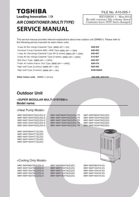
Outdoor Unit<br />
<br />
Model name:<br />
<br />
MMY-MAP0804HT8(Z)(ZG)-E<br />
MMY-MAP1004HT8(Z)(ZG)-E<br />
MMY-MAP1204HT8(Z)(ZG)-E<br />
MMY-MAP1404HT8(Z)(ZG)-E<br />
MMY-MAP1604HT8(Z)(ZG)-E<br />
MMY-MAP0804HT8(Z)(ZG)-TR<br />
MMY-MAP1004HT8(Z)(ZG)-TR<br />
MMY-MAP1204HT8(Z)(ZG)-TR<br />
MMY-MAP1404HT8(Z)(ZG)-TR<br />
MMY-MAP1604HT8(Z)(ZG)-TR<br />
MMY-MAP0804HT8(Z)(ZG)<br />
MMY-MAP1004HT8(Z)(ZG)<br />
MMY-MAP1204HT8(Z)(ZG)<br />
MMY-MAP1404HT8(Z)(ZG)<br />
MMY-MAP1604HT8(Z)(ZG)<br />
MMY-MAP0804HT7(Z)(ZG)<br />
MMY-MAP1004HT7(Z)(ZG)<br />
MMY-MAP1204HT7(Z)(ZG)<br />
MMY-MAP1404HT7(Z)(ZG)<br />
MMY-MAP1604HT7(Z)(ZG)<br />
<br />
MMY-MAP0804T8(Z)(ZG)-E<br />
MMY-MAP1004T8(Z)(ZG)-E<br />
MMY-MAP1204T8(Z)(ZG)-E<br />
MMY-MAP1404T8(Z)(ZG)-E<br />
MMY-MAP1604T8(Z)(ZG)-E<br />
MMY-MAP0804T8(Z)(ZG)<br />
MMY-MAP1004T8(Z)(ZG)<br />
MMY-MAP1204T8(Z)(ZG)<br />
MMY-MAP1404T8(Z)(ZG)<br />
MMY-MAP1604T8(Z)(ZG)<br />
MMY-MAP0804T8-SG<br />
MMY-MAP1004T8-SG<br />
MMY-MAP1204T8-SG<br />
MMY-MAP1404T8-SG<br />
MMY-MAP1604T8-SG
Contents<br />
Original instruction . . . . . . . . . . . . . . . . . . . . . . . . . . . . . . . . . . . . . . . . . . . . . . . . . . . . 5<br />
New Refrigerant (R410A). . . . . . . . . . . . . . . . . . . . . . . . . . . . . . . . . . . . . . . . . . . . . . . 21<br />
1 Wiring Diagrams . . . . . . . . . . . . . . . . . . . . . . . . . . . . . . . . . . . . . . . . . . . . . . . . . . . . . 23<br />
1-1. Outdoor Unit . . . . . . . . . . . . . . . . . . . . . . . . . . . . . . . . . . . . . . . . . . . . . . . . . . . . . . . . . . . . . . . . 23<br />
1-2. Indoor Unit . . . . . . . . . . . . . . . . . . . . . . . . . . . . . . . . . . . . . . . . . . . . . . . . . . . . . . . . . . . . . . . . . . 25<br />
1-2-1. 4-way Air Discharge Cassette Type . . . . . . . . . . . . . . . . . . . . . . . . . . . . . . . . . . . . . . . . 25<br />
1-2-2. Compact 4-way Cassette Type . . . . . . . . . . . . . . . . . . . . . . . . . . . . . . . . . . . . . . . . . . . 26<br />
1-2-3. 1-way Air Discharge Cassette Type (Compact type) . . . . . . . . . . . . . . . . . . . . . . . . . . . 27<br />
1-2-4. 1-way Air Discharge Cassette Type SH 2 series . . . . . . . . . . . . . . . . . . . . . . . . . . . . . . 28<br />
1-2-5. 2-way Air Discharge Cassette Type 1 series . . . . . . . . . . . . . . . . . . . . . . . . . . . . . . . . . 29<br />
1-2-6. 2-way Air Discharge Cassette Type 2 series . . . . . . . . . . . . . . . . . . . . . . . . . . . . . . . . . 30<br />
1-2-7. Concealed Duct Standard Type . . . . . . . . . . . . . . . . . . . . . . . . . . . . . . . . . . . . . . . . . . . 31<br />
1-2-8. Concealed Duct High Static Pressure Type . . . . . . . . . . . . . . . . . . . . . . . . . . . . . . . . . . 32<br />
1-2-9. Slim Duct Type . . . . . . . . . . . . . . . . . . . . . . . . . . . . . . . . . . . . . . . . . . . . . . . . . . . . . . . . 34<br />
1-2-10. Under Ceiling Type. . . . . . . . . . . . . . . . . . . . . . . . . . . . . . . . . . . . . . . . . . . . . . . . . . . . . 35<br />
1-2-11. High Wall Type 2 series . . . . . . . . . . . . . . . . . . . . . . . . . . . . . . . . . . . . . . . . . . . . . . . . . 36<br />
1-2-12. High Wall Type 3 series . . . . . . . . . . . . . . . . . . . . . . . . . . . . . . . . . . . . . . . . . . . . . . . . . 37<br />
1-2-13. Floor Standing Cabinet Type . . . . . . . . . . . . . . . . . . . . . . . . . . . . . . . . . . . . . . . . . . . . . 38<br />
1-2-14. Floor Standing Concealed Type. . . . . . . . . . . . . . . . . . . . . . . . . . . . . . . . . . . . . . . . . . . 39<br />
1-2-15. Floor Standing Type . . . . . . . . . . . . . . . . . . . . . . . . . . . . . . . . . . . . . . . . . . . . . . . . . . . . 40<br />
1-2-16. Fresh Air Intake Indoor Unit for S-MMS . . . . . . . . . . . . . . . . . . . . . . . . . . . . . . . . . . . . . 41<br />
2 Parts Rating . . . . . . . . . . . . . . . . . . . . . . . . . . . . . . . . . . . . . . . . . . . . . . . . . . . . . . . . . 43<br />
2-1. Outdoor Unit (50Hz model: MMY-MAP4HT8-E, MAP4HT8-TR, MAP4HT8, MAP4T8-<br />
SG) . . . . . . . . . . . . . . . . . . . . . . . . . . . . . . . . . . . . . . . . . . . . . . . . . . . . . . . . . . . . . . . . . . . . . . . 43<br />
2-2. Outdoor Unit (60Hz model: MMY-MAP4HT7) . . . . . . . . . . . . . . . . . . . . . . . . . . . . . . . . . . . . 44<br />
2-3. Outdoor Inverter (50Hz model: MMY-MAP4HT8-E, MAP4HT8-TR, MAP4HT8,<br />
MAP4T8-SG) . . . . . . . . . . . . . . . . . . . . . . . . . . . . . . . . . . . . . . . . . . . . . . . . . . . . . . . . . . . . . 45<br />
2-4. Outdoor Inverter (60Hz model: MMY-MAP4HT7) . . . . . . . . . . . . . . . . . . . . . . . . . . . . . . . . . 46<br />
2-5. Indoor Unit . . . . . . . . . . . . . . . . . . . . . . . . . . . . . . . . . . . . . . . . . . . . . . . . . . . . . . . . . . . . . . . . . . 47<br />
2-6. Parts Layout in Outdoor Unit . . . . . . . . . . . . . . . . . . . . . . . . . . . . . . . . . . . . . . . . . . . . . . . . . . . . 53<br />
2-7. Parts Layout in Inverter Assembly. . . . . . . . . . . . . . . . . . . . . . . . . . . . . . . . . . . . . . . . . . . . . . . . 55<br />
2-8. Outdoor (Inverter) Print Circuit Board . . . . . . . . . . . . . . . . . . . . . . . . . . . . . . . . . . . . . . . . . . . . . 57<br />
2-8-1. Interface P.C. board (MCC-1606) . . . . . . . . . . . . . . . . . . . . . . . . . . . . . . . . . . . . . . . . . 57<br />
2-8-2. Inverter P.C. board for compressor (MCC-1596) A3-IPDU . . . . . . . . . . . . . . . . . . . . . . 58<br />
2-8-3. Inverter P.C. board for fan (MCC-1610) . . . . . . . . . . . . . . . . . . . . . . . . . . . . . . . . . . . . . 59<br />
3 Refrigerant Piping Systematic Drawing . . . . . . . . . . . . . . . . . . . . . . . . . . . . . . . . . . 60<br />
4 Combined Refrigerant Piping System Schematic Diagrams. . . . . . . . . . . . . . . . . . 64<br />
1
4-1. Normal Operation (COOL Mode / DEFROST Mode) - High Outside Air Temperature (Roughly 20<br />
°C or Above) . . . . . . . . . . . . . . . . . . . . . . . . . . . . . . . . . . . . . . . . . . . . . . . . . . . . . . . . . . . . . . . . 64<br />
4-2. Normal Operation (COOL Mode) - Low Outside Air Temperature (Roughly Below 20 °C) . . . . . 65<br />
4-3. Normal Operation (HEAT Mode) . . . . . . . . . . . . . . . . . . . . . . . . . . . . . . . . . . . . . . . . . . . . . . . . . 66<br />
4-4. Emergency Operation (Cooling Operation under Header Outdoor Unit Backup Scenario). . . . . 67<br />
4-5. Emergency Operation (Heating Operation under Header Outdoor Unit Backup Scenario). . . . . 68<br />
4-6. Refrigerant Recovery from Failed Outdoor Unit (Pump-Down Operation under Follower Outdoor<br />
Unit Backup Scenario). . . . . . . . . . . . . . . . . . . . . . . . . . . . . . . . . . . . . . . . . . . . . . . . . . . . . . . . . 69<br />
5 Control Outline. . . . . . . . . . . . . . . . . . . . . . . . . . . . . . . . . . . . . . . . . . . . . . . . . . . . . . . 70<br />
6 Applied Control and Functions (including Circuit Configuration) . . . . . . . . . . . . . 85<br />
6-1. Indoor Controller Block Diagram . . . . . . . . . . . . . . . . . . . . . . . . . . . . . . . . . . . . . . . . . . . . . . . . . 85<br />
6-1-1. When Main (Sub) Remote Controller Connected. . . . . . . . . . . . . . . . . . . . . . . . . . . . . . 85<br />
6-1-2. When Wireless Remote Controller Kit Connected . . . . . . . . . . . . . . . . . . . . . . . . . . . . . 88<br />
6-1-3. When Both Main (Sub) Remote Controller and Wireless Remote Controller Kit Connected .91<br />
6-2. Indoor Printed Circuit Board . . . . . . . . . . . . . . . . . . . . . . . . . . . . . . . . . . . . . . . . . . . . . . . . . . . . 94<br />
6-3. Optional Connector Specifications of Indoor P.C. Board. . . . . . . . . . . . . . . . . . . . . . . . . . . . . . . 97<br />
6-4. Test Operation of Indoor Unit . . . . . . . . . . . . . . . . . . . . . . . . . . . . . . . . . . . . . . . . . . . . . . . . . . . 98<br />
6-5. Method to Set Indoor Unit Function DN Code . . . . . . . . . . . . . . . . . . . . . . . . . . . . . . . . . . . . . . . 99<br />
6-6. Applied Control of Indoor Unit . . . . . . . . . . . . . . . . . . . . . . . . . . . . . . . . . . . . . . . . . . . . . . . . . 103<br />
6-7. Applied control for Outdoor Unit . . . . . . . . . . . . . . . . . . . . . . . . . . . . . . . . . . . . . . . . . . . . . . . . 106<br />
6-7-1. Outdoor Fan High Static Pressure Shift . . . . . . . . . . . . . . . . . . . . . . . . . . . . . . . . . . . . 106<br />
6-7-2. Priority Operation Mode Setting . . . . . . . . . . . . . . . . . . . . . . . . . . . . . . . . . . . . . . . . . . 107<br />
6-8. Applied Control of Outdoor Unit. . . . . . . . . . . . . . . . . . . . . . . . . . . . . . . . . . . . . . . . . . . . . . . . . 109<br />
6-8-1. Power peak-cut Control (Standard) . . . . . . . . . . . . . . . . . . . . . . . . . . . . . . . . . . . . . . . 110<br />
6-8-2. Power peak-cut Control (Extended) . . . . . . . . . . . . . . . . . . . . . . . . . . . . . . . . . . . . . . . 111<br />
6-8-3. Snowfall Fan Control . . . . . . . . . . . . . . . . . . . . . . . . . . . . . . . . . . . . . . . . . . . . . . . . . . 112<br />
6-8-4. External master ON/OFF Control . . . . . . . . . . . . . . . . . . . . . . . . . . . . . . . . . . . . . . . . . 112<br />
6-8-5. Night operation (sound reduction) Control . . . . . . . . . . . . . . . . . . . . . . . . . . . . . . . . . . 113<br />
6-8-6. Operation Mode Selection Control . . . . . . . . . . . . . . . . . . . . . . . . . . . . . . . . . . . . . . . . 114<br />
6-8-7. Error/Operation Output. . . . . . . . . . . . . . . . . . . . . . . . . . . . . . . . . . . . . . . . . . . . . . . . . 115<br />
6-8-8. Compressor Operation Output . . . . . . . . . . . . . . . . . . . . . . . . . . . . . . . . . . . . . . . . . . . 116<br />
6-8-9. Operating Rate Output . . . . . . . . . . . . . . . . . . . . . . . . . . . . . . . . . . . . . . . . . . . . . . . . . 117<br />
7 TEST OPERATION . . . . . . . . . . . . . . . . . . . . . . . . . . . . . . . . . . . . . . . . . . . . . . . . . . . 118<br />
7-1. Procedure and Summary of Test Operation . . . . . . . . . . . . . . . . . . . . . . . . . . . . . . . . . . . . . . . 118<br />
7-2. Check Items before Test Operation (before powering-on) . . . . . . . . . . . . . . . . . . . . . . . . . . . . 119<br />
7-3. Check at Main Power-on . . . . . . . . . . . . . . . . . . . . . . . . . . . . . . . . . . . . . . . . . . . . . . . . . . . . . . 123<br />
7-4. Address Setup . . . . . . . . . . . . . . . . . . . . . . . . . . . . . . . . . . . . . . . . . . . . . . . . . . . . . . . . . . . . . . 124<br />
7-4-1. Precautions . . . . . . . . . . . . . . . . . . . . . . . . . . . . . . . . . . . . . . . . . . . . . . . . . . . . . . . . . 124<br />
7-4-2. Address Setup and Check Procedure . . . . . . . . . . . . . . . . . . . . . . . . . . . . . . . . . . . . . 124<br />
7-4-3. Address Setup Procedure . . . . . . . . . . . . . . . . . . . . . . . . . . . . . . . . . . . . . . . . . . . . . . 125<br />
7-4-4. Check after Address Setup when Central Control System Is Connected . . . . . . . . . . 138<br />
2
7-5. Troubleshooting in Test Operation . . . . . . . . . . . . . . . . . . . . . . . . . . . . . . . . . . . . . . . . . . . . . . 139<br />
7-5-1. A Check Code Is Displayed on the Remote Controller . . . . . . . . . . . . . . . . . . . . . . . . 139<br />
7-5-2. Operation from the indoor remote controller is not accepted, and a check code is displayed<br />
on the 7-segment display of the interface PC board of the header unit. . . . . . . . . . . . 140<br />
7-5-3. There is no display of a check code on the 7-segment display on the interface PC board of<br />
the header unit, although there is indoor unit that is not accepting operation from the indoor<br />
remote controller. . . . . . . . . . . . . . . . . . . . . . . . . . . . . . . . . . . . . . . . . . . . . . . . . . . . . . 140<br />
7-5-4. In checking the number of connected outdoor units and connected indoor units after address<br />
setup, a lower number of connected units is displayed. (There are outdoor/indoor<br />
units that do not operate in a test operation.). . . . . . . . . . . . . . . . . . . . . . . . . . . . . . . . 141<br />
7-6. Test Operation Check . . . . . . . . . . . . . . . . . . . . . . . . . . . . . . . . . . . . . . . . . . . . . . . . . . . . . . . . 143<br />
7-6-1. Fan Check . . . . . . . . . . . . . . . . . . . . . . . . . . . . . . . . . . . . . . . . . . . . . . . . . . . . . . . . . . 143<br />
7-6-2. Cooling/Heating Test Operation Check . . . . . . . . . . . . . . . . . . . . . . . . . . . . . . . . . . . . 144<br />
7-7. Service Support Function . . . . . . . . . . . . . . . . . . . . . . . . . . . . . . . . . . . . . . . . . . . . . . . . . . . . . 148<br />
7-7-1. Check Function for Connecting of Refrigerant and Control Lines . . . . . . . . . . . . . . . . 148<br />
7-7-2. Function to Start/Stop (ON/OFF) Indoor Unit from Outdoor Unit . . . . . . . . . . . . . . . . . 150<br />
7-7-3. Error Clearing Function . . . . . . . . . . . . . . . . . . . . . . . . . . . . . . . . . . . . . . . . . . . . . . . . 155<br />
7-7-4. Remote Controller Distinction Function . . . . . . . . . . . . . . . . . . . . . . . . . . . . . . . . . . . . 157<br />
7-7-5. Pulse Motor Valve (PMV) Forced Open/Close Function in Indoor Unit . . . . . . . . . . . . 158<br />
7-7-6. Pulse Motor Valve (PMV) Forced Open Fully/Close fully Function in Outdoor Unit. . . 158<br />
7-7-7. Solenoid Valve Forced Open/Close Function in Outdoor Unit . . . . . . . . . . . . . . . . . . . 159<br />
7-7-8. Fan Operation Check in Outdoor Unit . . . . . . . . . . . . . . . . . . . . . . . . . . . . . . . . . . . . . 160<br />
7-7-9. Abnormal Outdoor Unit Discrimination Method By Fan Operating Function . . . . . . . . 161<br />
7-7-10. Manual Adjustment Function of Outside Temperature (TO) Sensor . . . . . . . . . . . . . . 162<br />
7-7-11. Monitor Function of Remote Controller Switch. . . . . . . . . . . . . . . . . . . . . . . . . . . . . . . 164<br />
8 TROUBLESHOOTING . . . . . . . . . . . . . . . . . . . . . . . . . . . . . . . . . . . . . . . . . . . . . . . . 166<br />
8-1. Overview . . . . . . . . . . . . . . . . . . . . . . . . . . . . . . . . . . . . . . . . . . . . . . . . . . . . . . . . . . . . . . . . . . 166<br />
8-2. Troubleshooting Method . . . . . . . . . . . . . . . . . . . . . . . . . . . . . . . . . . . . . . . . . . . . . . . . . . . . . . 167<br />
8-3. Troubleshooting Based on Information Displayed on Remote Controller . . . . . . . . . . . . . . . . . 173<br />
8-4. Check Codes Displayed on Remote Controller and SMMS-i Outdoor Unit (7-Segment Display on I/<br />
F Board) and Locations to Be Checked. . . . . . . . . . . . . . . . . . . . . . . . . . . . . . . . . . . . . . . . . . . 178<br />
8-5. Diagnosis procedure for each check code . . . . . . . . . . . . . . . . . . . . . . . . . . . . . . . . . . . . . . . . 194<br />
8-6. 7-Segment Display Function . . . . . . . . . . . . . . . . . . . . . . . . . . . . . . . . . . . . . . . . . . . . . . . . . . . 225<br />
8-7. Oil Level Judgment Display . . . . . . . . . . . . . . . . . . . . . . . . . . . . . . . . . . . . . . . . . . . . . . . . . . . . 231<br />
8-8. Leakage/Clogging of Refrigerating Cycle Circuit. . . . . . . . . . . . . . . . . . . . . . . . . . . . . . . . . . . . 232<br />
8-9. Sensor Characteristics . . . . . . . . . . . . . . . . . . . . . . . . . . . . . . . . . . . . . . . . . . . . . . . . . . . . . . . 236<br />
8-10. Pressure Sensor Output Check. . . . . . . . . . . . . . . . . . . . . . . . . . . . . . . . . . . . . . . . . . . . . . . . . 239<br />
9 BACKUP OPERATION (EMERGENCY OPERATION) . . . . . . . . . . . . . . . . . . . . . . . 241<br />
9-1. Note for Backup Operation . . . . . . . . . . . . . . . . . . . . . . . . . . . . . . . . . . . . . . . . . . . . . . . . . . . . 241<br />
9-2. Compressor Backup Operation Setting . . . . . . . . . . . . . . . . . . . . . . . . . . . . . . . . . . . . . . . . . . . 242<br />
9-3. Outdoor Unit Backup Operation Setting . . . . . . . . . . . . . . . . . . . . . . . . . . . . . . . . . . . . . . . . . . 243<br />
9-3-1. Follower outdoor unit backup operation setting (failure of follower outdoor unit) . . . . . 243<br />
9-3-2. Header outdoor unit backup operation setting (failure of header outdoor unit) . . . . . . 245<br />
3
9-4. Cooling-Season Outdoor Unit Backup Operation Setting . . . . . . . . . . . . . . . . . . . . . . . . . . . . . 247<br />
10 OUTDOOR UNIT REFRIGERANT RECOVERY METHOD . . . . . . . . . . . . . . . . . . . . 248<br />
10-1. Refrigerant Recovery from Failed Outdoor Unit (Pump-Down) . . . . . . . . . . . . . . . . . . . . . . . . . 248<br />
10-1-1. Note for refrigerant recovery operation . . . . . . . . . . . . . . . . . . . . . . . . . . . . . . . . . . . . 248<br />
10-1-2. Refrigerant recovery procedure A (Case of no outdoor unit backup operation setting) 248<br />
10-1-3. Refrigerant recovery procedure B (Case of outdoor unit backup operation setting) . . 251<br />
10-2. How to Operate System While Failed Outdoor Unit Being Repaired. . . . . . . . . . . . . . . . . . . . . 253<br />
10-3. Work procedure after Repair . . . . . . . . . . . . . . . . . . . . . . . . . . . . . . . . . . . . . . . . . . . . . . . . . . . 254<br />
11 REPLACING COMPRESSORS . . . . . . . . . . . . . . . . . . . . . . . . . . . . . . . . . . . . . . . . . 255<br />
11-1. Compressor Replacement Procedure (Outline). . . . . . . . . . . . . . . . . . . . . . . . . . . . . . . . . . . . . 255<br />
11-2. Replacement of Compressors . . . . . . . . . . . . . . . . . . . . . . . . . . . . . . . . . . . . . . . . . . . . . . . . . . 256<br />
11-3. Check Procedure to Search Cause of Compressor Oil Shortage . . . . . . . . . . . . . . . . . . . . . . . 260<br />
12 OUTDOOR UNIT PARTS REPLACEMENT METHODS . . . . . . . . . . . . . . . . . . . . . . 263<br />
13 P.C. BOARD EXCHANGE PROCEDURES . . . . . . . . . . . . . . . . . . . . . . . . . . . . . . . . 276<br />
13-1. Replacement of Indoor P.C. Boards . . . . . . . . . . . . . . . . . . . . . . . . . . . . . . . . . . . . . . . . . . . . . 276<br />
13-2. Replacement of Outdoor P.C. Boards . . . . . . . . . . . . . . . . . . . . . . . . . . . . . . . . . . . . . . . . . . . . 283<br />
13-2-1. List of service P.C. boards . . . . . . . . . . . . . . . . . . . . . . . . . . . . . . . . . . . . . . . . . . . . . . 283<br />
13-2-2. Configuration of inverter assembly. . . . . . . . . . . . . . . . . . . . . . . . . . . . . . . . . . . . . . . . 283<br />
13-2-3. Interface board (MCC-1606) replacement method. . . . . . . . . . . . . . . . . . . . . . . . . . . . 284<br />
13-2-4. Comp-IPDU P.C. Board (MCC-1596) Replacement Procedure. . . . . . . . . . . . . . . . . . 285<br />
13-2-5. Fan IPDU P.C. Board (MCC-1610) Replacement Procedure . . . . . . . . . . . . . . . . . . . 287<br />
13-2-6. Noise Filter P.C. Board (MCC-1608 A, B) Replacement Procedure . . . . . . . . . . . . . . 288<br />
14 EXPLODED DIAGRAM/PARTS PRICE LIST. . . . . . . . . . . . . . . . . . . . . . . . . . . . . . . 291<br />
4
Original instruction<br />
Please read carefully through these instructions that contain important information which complies with the<br />
“Machinery” Directive (Directive 2006/42/EC), and ensure that you understand them.<br />
Some of the details provided in these instructions differ from the service manual, and the instructions provided here<br />
take precedence.<br />
Generic Denomination: Air Conditioner<br />
Definition of Qualified Installer or Qualified Service Person<br />
The air conditioner must be installed, maintained, repaired and removed by a qualified installer or qualified service<br />
person. When any of these jobs is to be done, ask a qualified installer or qualified service person to do them for you.<br />
A qualified installer or qualified service person is an agent who has the qualifications and knowledge described in<br />
the table below.<br />
Agent<br />
Qualified installer<br />
Qualified service<br />
person<br />
Qualifications and knowledge which the agent must have<br />
• The qualified installer is a person who installs, maintains, relocates and removes the air conditioners<br />
made by Toshiba Carrier Corporation. He or she has been trained to install, maintain, relocate and<br />
remove the air conditioners made by Toshiba Carrier Corporation or, alternatively, he or she has been<br />
instructed in such operations by an individual or individuals who have been trained and is thus<br />
thoroughly acquainted with the knowledge related to these operations.<br />
• The qualified installer who is allowed to do the electrical work involved in installation, relocation and<br />
removal has the qualifications pertaining to this electrical work as stipulated by the local laws and<br />
regulations, and he or she is a person who has been trained in matters relating to electrical work on<br />
the air conditioners made by Toshiba Carrier Corporation or, alternatively, he or she has been<br />
instructed in such matters by an individual or individuals who have been trained and is thus thoroughly<br />
acquainted with the knowledge related to this work.<br />
• The qualified installer who is allowed to do the refrigerant handling and piping work involved in<br />
installation, relocation and removal has the qualifications pertaining to this refrigerant handling and<br />
piping work as stipulated by the local laws and regulations, and he or she is a person who has been<br />
trained in matters relating to refrigerant handling and piping work on the air conditioners made by<br />
Toshiba Carrier Corporation or, alternatively, he or she has been instructed in such matters by an<br />
individual or individuals who have been trained and is thus thoroughly acquainted with the knowledge<br />
related to this work.<br />
• The qualified installer who is allowed to work at heights has been trained in matters relating to working<br />
at heights with the air conditioners made by Toshiba Carrier Corporation or, alternatively, he or she<br />
has been instructed in such matters by an individual or individuals who have been trained and is thus<br />
thoroughly acquainted with the knowledge related to this work.<br />
• The qualified service person is a person who installs, repairs, maintains, relocates and removes the<br />
air conditioners made by Toshiba Carrier Corporation. He or she has been trained to install, repair,<br />
maintain, relocate and remove the air conditioners made by Toshiba Carrier Corporation or,<br />
alternatively, he or she has been instructed in such operations by an individual or individuals who have<br />
been trained and is thus thoroughly acquainted with the knowledge related to these operations.<br />
• The qualified service person who is allowed to do the electrical work involved in installation, repair,<br />
relocation and removal has the qualifications pertaining to this electrical work as stipulated by the local<br />
laws and regulations, and he or she is a person who has been trained in matters relating to electrical<br />
work on the air conditioners made by Toshiba Carrier Corporation or, alternatively, he or she has been<br />
instructed in such matters by an individual or individuals who have been trained and is thus thoroughly<br />
acquainted with the knowledge related to this work.<br />
• The qualified service person who is allowed to do the refrigerant handling and piping work involved in<br />
installation, repair, relocation and removal has the qualifications pertaining to this refrigerant handling<br />
and piping work as stipulated by the local laws and regulations, and he or she is a person who has<br />
been trained in matters relating to refrigerant handling and piping work on the air conditioners made<br />
by Toshiba Carrier Corporation or, alternatively, he or she has been instructed in such matters by an<br />
individual or individuals who have been trained and is thus thoroughly acquainted with the knowledge<br />
related to this work.<br />
• The qualified service person who is allowed to work at heights has been trained in matters relating to<br />
working at heights with the air conditioners made by Toshiba Carrier Corporation or, alternatively, he<br />
or she has been instructed in such matters by an individual or individuals who have been trained and<br />
is thus thoroughly acquainted with the knowledge related to this work.<br />
5
Definition of Protective Gear<br />
When the air conditioner is to be transported, installed, maintained, repaired or removed, wear protective gloves<br />
and ‘safety’ work clothing.<br />
In addition to such normal protective gear, wear the protective gear described below when undertaking the special<br />
work detailed in the table below.<br />
Failure to wear the proper protective gear is dangerous because you will be more susceptible to injury, burns,<br />
electric shocks and other injuries.<br />
All types of work<br />
Work undertaken<br />
Electrical-related work<br />
Work done at heights<br />
(50 cm or more)<br />
Transportation of heavy objects<br />
Repair of outdoor unit<br />
Protective gloves<br />
‘Safety’ working clothing<br />
Protective gear worn<br />
Gloves to provide protection for electricians and from heat<br />
Insulating shoes<br />
Clothing to provide protection from electric shock<br />
Helmets for use in industry<br />
Shoes with additional protective toe cap<br />
Gloves to provide protection for electricians and from heat<br />
The important contents concerned to the safety are described on the product itself and on this Service Manual.<br />
Please read this Service Manual after understanding the described items thoroughly in the following contents<br />
(Indications/Illustrated marks), and keep them.<br />
[Explanation of indications]<br />
Indication<br />
DANGER<br />
WARNING<br />
CAUTION<br />
Explanation<br />
Indicates contents assumed that an imminent danger causing a death or serious injury of<br />
the repair engineers and the third parties when an incorrect work has been executed.<br />
Indicates possibilities assumed that a danger causing a death or serious injury of the<br />
repair engineers, the third parties, and the users due to troubles of the product after work<br />
when an incorrect work has been executed.<br />
Indicates contents assumed that an injury or property damage (*) may be caused on the<br />
repair engineers, the third parties, and the users due to troubles of the product after work<br />
when an incorrect work has been executed.<br />
* Property damage: Enlarged damage concerned to property, furniture, and domestic animal/pet<br />
[Explanation of illustrated marks]<br />
Mark<br />
Explanation<br />
Indicates prohibited items (Forbidden items to do)<br />
The sentences near an illustrated mark describe the concrete prohibited contents.<br />
Indicates mandatory items (Compulsory items to do)<br />
The sentences near an illustrated mark describe the concrete mandatory contents.<br />
Indicates cautions (Including danger/warning)<br />
The sentences or illustration near or in an illustrated mark describe the concrete cautious contents.<br />
6
Warning Indications on the Air Conditioner Unit<br />
[Confirmation of warning label on the main unit]<br />
Confirm that labels are indicated on the specified positions<br />
If removing the label during parts replace, stick it as the original.<br />
Warning indication<br />
Description<br />
WARNING<br />
ELECTRICAL SHOCK HAZARD<br />
Disconnect all remote<br />
electric power supplies<br />
before servicing.<br />
WARNING<br />
ELECTRICAL SHOCK HAZARD<br />
Disconnect all remote electric power supplies before servicing.<br />
WARNING<br />
Moving parts.<br />
Do not operate unit with grille<br />
removed.<br />
Stop the unit before the servicing.<br />
WARNING<br />
Moving parts.<br />
Do not operate unit with grille removed.<br />
Stop the unit before the servicing.<br />
CAUTION<br />
High temperature parts.<br />
You might get burned<br />
when removing this panel.<br />
CAUTION<br />
High temperature parts.<br />
You might get burned when removing this panel.<br />
CAUTION<br />
Do not touch the aluminum<br />
fins of the unit.<br />
Doing so may result in injury.<br />
CAUTION<br />
Do not touch the aluminium fins of the unit.<br />
Doing so may result in injury.<br />
CAUTION<br />
BURST HAZARD<br />
Open the service valves before<br />
the operation, otherwise there<br />
might be the burst.<br />
CAUTION<br />
BURST HAZARD<br />
Open the service valves before the operation, otherwise there might be the<br />
burst.<br />
CAUTION<br />
Do not climb onto the<br />
fan guard.<br />
Doing so may result in injury.<br />
CAUTION<br />
Do not climb onto the fan guard.<br />
Doing so may result in injury.<br />
7
Precautions for Safety<br />
The manufacturer shall not assume any liability for the damage caused by not observing the description of this<br />
manual.<br />
DANGER<br />
Turn off<br />
breaker.<br />
Before carrying out the installation, maintenance, repair or removal work, be sure to set the circuit breaker for<br />
both the indoor and outdoor units to the OFF position. Otherwise, electric shocks may result.<br />
Before opening the intake grille of the indoor unit or service panel of the outdoor unit, set the circuit breaker to<br />
the OFF position.<br />
Failure to set the circuit breaker to the OFF position may result in electric shocks through contact with the interior<br />
parts.<br />
Only a qualified installer (*1) or qualified service person (*1) is allowed to remove the intake grille of the indoor<br />
unit or service panel of the outdoor unit and do the work required.<br />
Before starting to repair the outdoor unit fan or fan guard, be absolutely sure to set the circuit<br />
breaker to the OFF position, and place a “Work in progress” sign on the circuit breaker.<br />
When cleaning the filter or other parts of the indoor unit, set the circuit breaker to OFF without<br />
fail, and place a “Work in progress” sign near the circuit breaker before proceeding with the work.<br />
When you have noticed that some kind of trouble (such as when an error display has appeared, there is a smell<br />
of burning, abnormal sounds are heard, the air conditioner fails to cool or heat or water is leaking) has occurred<br />
in the air conditioner, do not touch the air conditioner yourself but set the circuit breaker to the OFF position,<br />
and contact a qualified service person. Take steps to ensure that the power will not be turned on (by marking<br />
“out of service” near the circuit breaker, for instance) until qualified service person arrives. Continuing to use the<br />
air conditioner in the trouble status may cause mechanical problems to escalate or result in electric shocks or<br />
other failure.<br />
Electric shock<br />
hazard<br />
Prohibition<br />
Stay on<br />
protection<br />
When you access inside of the service panel to repair electric parts, wait for about five minutes after turning off<br />
the breaker. Do not start repairing immediately.Otherwise you may get electric shock by touching terminals of<br />
high-voltage capacitors. Natural discharge of the capacitor takes about five minutes.<br />
Place a “Work in progress” sign near the circuit breaker while the installation, maintenance, repair or removal<br />
work is being carried out.<br />
There is a danger of electric shocks if the circuit breaker is set to ON by mistake.<br />
Before operating the air conditioner after having completed the work, check that the electrical parts box cover<br />
of the indoor unit and service panel of the outdoor unit are closed, and set the circuit breaker to the ON position.<br />
You may receive an electric shock if the power is turned on without first conducting these checks.<br />
If, in the course of carrying out repairs, it becomes absolutely necessary to check out the electrical parts with<br />
the electrical parts box cover of one or more of the indoor units and the service panel of the outdoor unit<br />
removed in order to find out exactly where the trouble lies, wear insulated heat-resistant gloves, insulated boots<br />
and insulated work overalls, and take care to avoid touching any live parts.<br />
You may receive an electric shock if you fail to heed this warning. Only qualified service person (*1) is allowed<br />
to do this kind of work.<br />
8
WARNING<br />
General<br />
Check earth<br />
wires.<br />
Before starting to repair the air conditioner, read carefully through the Service Manual, and repair the air<br />
conditioner by following its instructions.<br />
Only qualified service person (*1) is allowed to repair the air conditioner.<br />
Repair of the air conditioner by unqualified person may give rise to a fire, electric shocks, injury, water leaks<br />
and/or other problems.<br />
Do not use any refrigerant different from the one specified for complement or replacement.<br />
Otherwise, abnormally high pressure may be generated in the refrigeration cycle, which may result in a failure<br />
or explosion of the product or an injury to your body.<br />
Only a qualified installer (*1) or qualified service person (*1) is allowed to carry out the electrical work of the air<br />
conditioner.<br />
Under no circumstances must this work be done by an unqualified individual since failure to carry out the work<br />
properly may result in electric shocks and/or electrical leaks.<br />
When transporting the air conditioner, wear shoes with protective toe caps, protective gloves and other<br />
protective clothing.<br />
When connecting the electrical wires, repairing the electrical parts or undertaking other electrical jobs, wear<br />
gloves to provide protection for electricians and from heat, insulating shoes and clothing to provide protection<br />
from electric shocks.<br />
Failure to wear this protective gear may result in electric shocks.<br />
Electrical wiring work shall be conducted according to law and regulation in the community and installation<br />
manual. Failure to do so may result in electrocution or short circuit.<br />
Only a qualified installer (*1) or qualified service person (*1) is allowed to undertake work at<br />
heights using a stand of 50 cm or more or to remove the intake grille of the indoor unit to<br />
undertake work.<br />
When working at heights, use a ladder which complies with the ISO 14122 standard, and follow the procedure<br />
in the ladder’s instructions.<br />
Also wear a helmet for use in industry as protective gear to undertake the work.<br />
When working at heights, put a sign in place so that no-one will approach the work location, before proceeding<br />
with the work.<br />
Parts and other objects may fall from above, possibly injuring a person below.<br />
When executing address setting, test run, or troubleshooting through the checking window on the electric parts<br />
box, put on insulated gloves to provide protection from electric shock. Otherwise you may receive an electric<br />
shock.<br />
Do not touch the aluminum fin of the outdoor unit.<br />
You may injure yourself if you do so. If the fin must be touched for some reason, first put on protective gloves<br />
and safety work clothing, and then proceed.<br />
Do not climb onto or place objects on top of the outdoor unit.<br />
You may fall or the objects may fall off of the outdoor unit and result in injury.<br />
When transporting the air conditioner, wear shoes with additional protective toe caps.<br />
When transporting the air conditioner, do not take hold of the bands around the packing carton.<br />
You may injure yourself if the bands should break.<br />
Be sure that a heavy unit (10kg or heavier) such as a compressor is carried by two persons.<br />
This air conditioner has passed the pressure test as specified in IEC 60335-2-40 Annex EE.<br />
Before troubleshooting or repair work, check the earth wire is connected to the earth terminals of the main unit,<br />
otherwise an electric shock is caused when a leak occurs.If the earth wire is not correctly connected, contact<br />
an electric engineer for rework.<br />
After completing the repair or relocation work, check that the ground wires are connected properly.<br />
Be sure to connect earth wire. (Grounding work) Incomplete grounding causes an electric shock.<br />
Do not connect ground wires to gas pipes, water pipes, and lightning rods or ground wires for telephone wires.<br />
Prohibition of<br />
modification.<br />
Do not modify the products.Do not also disassemble or modify the parts.<br />
It may cause a fire, electric shock or injury.<br />
9
Use specified<br />
parts.<br />
When any of the electrical parts are to be replaced, ensure that the replacement parts satisfy the specifications<br />
given in the Service Manual (or use the parts contained on the parts list in the Service Manual).<br />
Use of any parts which do not satisfy the required specifications may give rise to electric shocks, smoking and/<br />
or a fire.<br />
Do not bring a<br />
child close to<br />
the<br />
equipment.<br />
If, in the course of carrying out repairs, it becomes absolutely necessary to check out the electrical parts with<br />
the electrical parts box cover of one or more of the indoor units and the service panel of the outdoor unit<br />
removed in order to find out exactly where the trouble lies, put a sign in place so that no-one will approach the<br />
work location before proceeding with the work. Third-party individuals may enter the work site and receive<br />
electric shocks if this warning is not heeded.<br />
Insulating<br />
measures<br />
No fire<br />
Refrigerant<br />
Assembly/<br />
Wiring<br />
Connect the cut-off lead wires with crimp contact, etc., put the closed end side upward and then apply a watercut<br />
method, otherwise a leak or production of fire is caused at the users’ side.<br />
When performing repairs using a gas burner, replace the refrigerant with nitrogen gas because the oil that coats<br />
the pipes may otherwise burn.<br />
When repairing the refrigerating cycle, take the following measures.<br />
1) Be attentive to fire around the cycle. When using a gas stove, etc., be sure to put out fire before work;<br />
otherwise the oil mixed with refrigerant gas may catch fire.<br />
2) Do not use a welder in the closed room. When using it without ventilation, carbon monoxide poisoning may<br />
be caused.<br />
3) Do not bring inflammables close to the refrigerant cycle, otherwise fire of the welder may catch the<br />
inflammables.<br />
The refrigerant used by this air conditioner is the R410A.<br />
Check the used refrigerant name and use tools and materials of the parts which match with it.<br />
For the products which use R410A refrigerant, the refrigerant name is indicated at a position on the outdoor unit<br />
where is easy to see. To prevent miss-charging, the route of the service port is changed from one of the former<br />
R22.<br />
For an air conditioner which uses R410A, never use other refrigerant than R410A. For an air conditioner which<br />
uses other refrigerant (R22, etc.), never use R410A.<br />
If different types of refrigerant are mixed, abnormal high pressure generates in the refrigerating cycle and an<br />
injury due to breakage may be caused.<br />
When the air conditioner has been installed or relocated, follow the instructions in the Installation Manual and<br />
purge the air completely so that no gases other than the refrigerant will be mixed in the refrigerating cycle.<br />
Failure to purge the air completely may cause the air conditioner to malfunction.<br />
Do not charge refrigerant additionally. If charging refrigerant additionally when refrigerant gas leaks, the<br />
refrigerant composition in the refrigerating cycle changes resulted in change of air conditioner characteristics or<br />
refrigerant over the specified standard amount is charged and an abnormal high pressure is applied to the inside<br />
of the refrigerating cycle resulted in cause of breakage or injury. Therefore if the refrigerant gas leaks, recover<br />
the refrigerant in the air conditioner, execute vacuuming, and then newly recharge the specified amount of liquid<br />
refrigerant.<br />
In this time, never charge the refrigerant over the specified amount.<br />
When recharging the refrigerant in the refrigerating cycle, do not mix the refrigerant or air other than R410A into<br />
the specified refrigerant. If air or others is mixed with the refrigerant, abnormal high pressure generates in the<br />
refrigerating cycle resulted in cause of injury due to breakage.<br />
After installation work, check the refrigerant gas does not leak. If the refrigerant gas leaks in the room,<br />
poisonous gas generates when gas touches to fire such as fan heater, stove or cocking stove though the<br />
refrigerant gas itself is innocuous.<br />
Never recover the refrigerant into the outdoor unit. When the equipment is moved or repaired, be sure to recover<br />
the refrigerant with recovering device.<br />
The refrigerant cannot be recovered in the outdoor unit; otherwise a serious accident such as breakage or injury<br />
is caused.<br />
After repair work, surely assemble the disassembled parts, and connect and lead the removed wires as before.<br />
Perform the work so that the cabinet or panel does not catch the inner wires.<br />
If incorrect assembly or incorrect wire connection was done, a disaster such as a leak or fire is caused at user’s<br />
side.<br />
Insulator<br />
check<br />
After the work has finished, be sure to use an insulation tester set (500V Megger) to check the resistance is<br />
1M or more between the charge section and the non-charge metal section (Earth position).<br />
If the resistance value is low, a disaster such as a leak or electric shock is caused at user’s side.<br />
10
Ventilation<br />
Compulsion<br />
Check after<br />
repair<br />
Do not<br />
operate the<br />
unit with the<br />
valve closed.<br />
Check after<br />
reinstallation<br />
Cooling check<br />
When the refrigerant gas leaks during work, execute ventilation.<br />
If the refrigerant gas touches to a fire, poisonous gas generates. A case of leakage of the refrigerant and the<br />
closed room full with gas is dangerous because a shortage of oxygen occurs. Be sure to execute ventilation.<br />
When the refrigerant gas leaks, find up the leaked position and repair it surely.<br />
If the leaked position cannot be found up and the repair work is interrupted, pump-down and tighten the service<br />
valve, otherwise the refrigerant gas may leak into the room.<br />
The poisonous gas generates when gas touches to fire such as fan heater, stove or cocking stove though the<br />
refrigerant gas itself is innocuous.<br />
When installing equipment which includes a large amount of charged refrigerant such as a multi air conditioner<br />
in a sub-room, it is necessary that the density does not the limit even if the refrigerant leaks.<br />
If the refrigerant leaks and exceeds the limit density, an accident of shortage of oxygen is caused.<br />
Tighten the flare nut with a torque wrench in the specified manner.<br />
Excessive tighten of the flare nut may cause a crack in the flare nut after a long period, which may result in<br />
refrigerant leakage.<br />
Nitrogen gas must be used for the airtight test.<br />
The charge hose must be connected in such a way that it is not slack.<br />
For the installation/moving/reinstallation work, follow to the Installation Manual.<br />
If an incorrect installation is done, a trouble of the refrigerating cycle, water leak, electric shock or fire is caused.<br />
Once the repair work has been completed, check for refrigerant leaks, and check the insulation resistance and<br />
water drainage.<br />
Then perform a trial run to check that the air conditioner is running properly.<br />
After repair work has finished, check there is no trouble. If check is not executed, a fire, electric shock or injury<br />
may be caused. For a check, turn off the power breaker.<br />
After repair work (installation of front panel and cabinet) has finished, execute a test run to check there is no<br />
generation of smoke or abnormal sound.<br />
If check is not executed, a fire or an electric shock is caused. Before test run, install the front panel and cabinet.<br />
Be sure to fix the screws back which have been removed for installation or other purposes.<br />
Check the following matters before a test run after repairing piping.<br />
• Connect the pipes surely and there is no leak of refrigerant.<br />
• The valve is opened.<br />
Running the compressor under condition that the valve closes causes an abnormal high pressure resulted in<br />
damage of the parts of the compressor and etc. and moreover if there is leak of refrigerant at connecting section<br />
of pipes, the air is sucked and causes further abnormal high pressure resulted in burst or injury.<br />
Only a qualified installer (*1) or qualified service person (*1) is allowed to relocate the air conditioner. It is<br />
dangerous for the air conditioner to be relocated by an unqualified individual since a fire, electric shocks, injury,<br />
water leakage, noise and/or vibration may result.<br />
Check the following items after reinstallation.<br />
1) The earth wire is correctly connected.<br />
2) The power cord is not caught in the product.<br />
3) There is no inclination or unsteadiness and the installation is stable.<br />
If check is not executed, a fire, an electric shock or an injury is caused.<br />
When carrying out the pump-down work shut down the compressor before disconnecting the refrigerant pipe.<br />
Disconnecting the refrigerant pipe with the service valve left open and the compressor still operating will cause<br />
air, etc. to be sucked in, raising the pressure inside the refrigeration cycle to an abnormally high level, and<br />
possibly resulting in reputing, injury, etc.<br />
When the service panel of the outdoor unit is to be opened in order for the compressor or the area around this<br />
part to be repaired immediately after the air conditioner has been shut down, set the circuit breaker to the OFF<br />
position, and then wait at least 10 minutes before opening the service panel.<br />
If you fail to heed this warning, you will run the risk of burning yourself because the compressor pipes and other<br />
parts will be very hot to the touch. In addition, before proceeding with the repair work, wear the kind of insulated<br />
heat-resistant gloves designed to protect electricians.<br />
Take care not to get burned by compressor pipes or other parts when checking the cooling cycle while running<br />
the unit as they get heated while running. Be sure to put on gloves providing protection for electric shock and<br />
heat.<br />
When the service panel of the outdoor unit is to be opened in order for the fan motor, reactor, inverter or the<br />
areas around these parts to be repaired immediately after the air conditioner has been shut down, set the circuit<br />
breaker to the OFF position, and then wait at least 10 minutes before opening the service panel.<br />
If you fail to heed this warning, you will run the risk of burning yourself because the fan motor, reactor, inverter<br />
heat sink and other parts will be very hot to the touch.<br />
In addition, before proceeding with the repair work, wear the kind of insulated heat-resistant gloves designed to<br />
protect electricians.<br />
11
Only a qualified installer (*1) or qualified service person (*1) is allowed to install the air conditioner. If the air<br />
conditioner is installed by an unqualified individual, a fire, electric shocks, injury, water leakage, noise and/or<br />
vibration may result.<br />
Before starting to install the air conditioner, read carefully through the Installation Manual, and follow its<br />
instructions to install the air conditioner.<br />
Be sure to use the company-specified products for the separately purchased parts. Use of non-specified<br />
products may result in fire, electric shock, water leakage or other failure. Have the installation performed by a<br />
qualified installer.<br />
Do not supply power from the power terminal block equipped on the outdoor unit to another outdoor unit.<br />
Capacity overflow may occur on the terminal block and may result in fire.<br />
Do not install the air conditioner in a location that may be subject to a risk of expire to a combustible gas.<br />
If a combustible gas leaks and becomes concentrated around the unit, a fire may occur.<br />
Installation<br />
Install the indoor unit at least 2.5 m above the floor level since otherwise the users may injure themselves or<br />
receive electric shocks if they poke their fingers or other objects into the indoor unit while the air conditioner is<br />
running.<br />
Install a circuit breaker that meets the specifications in the installation manual and the stipulations in the local<br />
regulations and laws.<br />
Install the circuit breaker where it can be easily accessed by the qualified service person (*1).<br />
If you install the unit in a small room, take appropriate measures to prevent the refrigerant from exceeding the<br />
limit concentration even if it leaks. Consult the dealer from whom you purchased the air conditioner when you<br />
implement the measures. Accumulation of highly concentrated refrigerant may cause an oxygen deficiency<br />
accident.<br />
Do not place any combustion appliance in a place where it is directly exposed to the wind of air conditioner,<br />
otherwise it may cause imperfect combustion.<br />
Explanations given to user<br />
• If you have discovered that the fan grille is damaged, do not approach the outdoor unit but set the circuit breaker<br />
to the OFF position, and contact a qualified service person to have the repairs done.<br />
Do not set the circuit breaker to the ON position until the repairs are completed.<br />
Relocation<br />
• Only a qualified installer (*1) or qualified service person (*1) is allowed to relocate the air conditioner.<br />
It is dangerous for the air conditioner to be relocated by an unqualified individual since a fire, electric shocks,<br />
injury, water leakage, noise and/or vibration may result.<br />
• When carrying out the pump-down work shut down the compressor before disconnecting the refrigerant pipe.<br />
Disconnecting the refrigerant pipe with the service valve left open and the compressor still operating will cause<br />
air, etc. to be sucked in, raising the pressure inside the refrigeration cycle to an abnormally high level, and<br />
possibly resulting in reputing, injury, etc.<br />
(*1) Refer to the “Definition of Qualified Installer or Qualified Service Person.”<br />
12
Declaration of Conformity<br />
Manufacturer:<br />
Authorized Representative/<br />
TCF holder:<br />
Toshiba Carrier Corporation<br />
336 Tadehara, Fuji-shi, Shizuoka-ken 416-8521 JAPAN<br />
Nick Ball<br />
Toshiba EMEA Engineering Director<br />
Toshiba Carrier UK Ltd.<br />
Porsham Close, Belliver Industrial Estate,<br />
PLYMOUTH, Devon, PL6 7DB.<br />
United Kingdom<br />
Hereby declares that the machinery described below:<br />
Generic Denomination:<br />
Model/type:<br />
Air Conditioner<br />
Outdoor unit<br />
<br />
MMY-MAP0804HT8(Z)(ZG)-E, MMY-MAP1004HT8(Z)(ZG)-E, MMY-MAP1204HT8(Z)(ZG)-E,<br />
MMY-MAP1404HT8(Z)(ZG)-E, MMY-MAP1604HT8(Z)(ZG)-E<br />
MMY-MAP0804HT8(Z)(ZG)-TR, MMY-MAP1004HT8(Z)(ZG)-TR, MMY-MAP1204HT8(Z)(ZG)-TR,<br />
MMY-MAP1404HT8(Z)(ZG)-TR, MMY-MAP1604HT8(Z)(ZG)-TR<br />
<br />
MMY-MAP0804T8(Z)(ZG)-E, MMY-MAP1004T8(Z)(ZG)-E, MMY-MAP1204T8(Z)(ZG)-E,<br />
MMY-MAP1404T8(Z)(ZG)-E, MMY-MAP1604T8(Z)(ZG)-E<br />
Commercial name:<br />
Super Modular Multi System Air Conditioner<br />
Complies with the provisions of the “Machinery” Directive (Directive 2006/42/EC) and the regulations transposing into national law<br />
Complies with the provisions of the following harmonized standard:<br />
EN 378-2: 2008+A1:2009<br />
NOTE<br />
This declaration becomes invalid if technical or operational modifications are introduced without the manufacturer’s<br />
consent.<br />
13
Specifications<br />
Model<br />
MMY-MAP0804HT8-E, MMY-MAP0804HT8Z-E,<br />
MMY-MAP0804HT8ZG-E<br />
MMY-MAP1004HT8-E, MMY-MAP1004HT8Z-E,<br />
MMY-MAP1004HT8ZG-E<br />
MMY-MAP1204HT8-E, MMY-MAP1204HT8Z-E,<br />
MMY-MAP1204HT8ZG-E<br />
MMY-MAP1404HT8-E, MMY-MAP1404HT8Z-E,<br />
MMY-MAP1404HT8ZG-E<br />
MMY-MAP1604HT8-E, MMY-MAP1604HT8Z-E,<br />
MMY-MAP1604HT8ZG-E<br />
MMY-MAP0804HT8-TR, MMY-MAP0804HT8Z-TR,<br />
MMY-MAP0804HT8ZGTR<br />
MMY-MAP1004HT8-TR, MMY-MAP1004HT8Z-TR,<br />
MMY-MAP1004HT8ZGTR<br />
MMY-MAP1204HT8-TR, MMY-MAP1204HT8Z-TR,<br />
MMY-MAP1204HT8ZGTR<br />
MMY-MAP1404HT8-TR, MMY-MAP1404HT8Z-TR,<br />
MMY-MAP1404HT8ZGTR<br />
MMY-MAP1604HT8-TR, MMY-MAP1604HT8Z-TR,<br />
MMY-MAP1604HT8ZGTR<br />
MMY-MAP0804HT8, MMY-MAP0804HT8Z,<br />
MMY-MAP0804HT8ZG<br />
MMY-MAP1004HT8, MMY-MAP1004HT8Z,<br />
MMY-MAP1004HT8ZG<br />
MMY-MAP1204HT8, MMY-MAP1204HT8Z,<br />
MMY-MAP1204HT8ZG<br />
MMY-MAP1404HT8, MMY-MAP1404HT8Z,<br />
MMY-MAP1404HT8ZG<br />
MMY-MAP1604HT8, MMY-MAP1604HT8Z,<br />
MMY-MAP1604HT8ZG<br />
MMY-MAP0804HT7, MMY-MAP0804HT7Z,<br />
MMY-MAP0804HT7ZG<br />
MMY-MAP1004HT7, MMY-MAP1004HT7Z,<br />
MMY-MAP1004HT7ZG<br />
MMY-MAP1204HT7, MMY-MAP1204HT7Z,<br />
MMY-MAP1204HT7ZG<br />
MMY-MAP1404HT7, MMY-MAP1404HT7Z,<br />
MMY-MAP1404HT7ZG<br />
MMY-MAP1604HT7, MMY-MAP1604HT7Z,<br />
MMY-MAP1604HT7ZG<br />
MMY-MAP0804T8-E, MMY-MAP0804T8Z-E,<br />
MMY-MAP0804T8ZG-E<br />
MMY-MAP1004T8-E, MMY-MAP1004T8Z-E,<br />
MMY-MAP1004T8ZG-E<br />
MMY-MAP1204T8-E, MMY-MAP1204T8Z-E,<br />
MMY-MAP1204T8ZG-E<br />
MMY-MAP1404T8-E, MMY-MAP1404T8Z-E,<br />
MMY-MAP1404T8ZG-E<br />
MMY-MAP1604T8-E, MMY-MAP1604T8Z-E,<br />
MMY-MAP1604T8ZG-E<br />
Sound power level (dBA)<br />
Cooling<br />
Heating<br />
Weight (kg)<br />
77 78 242<br />
78 79 242<br />
82 83 242<br />
82 83 330<br />
83 84 330<br />
77 78 242<br />
78 79 242<br />
82 83 242<br />
82 83 330<br />
83 84 330<br />
77 78 242<br />
78 79 242<br />
82 83 242<br />
82 83 330<br />
83 84 330<br />
77 78 242<br />
78 79 242<br />
82 83 242<br />
82 83 330<br />
83 84 330<br />
77 — 241<br />
78 — 241<br />
82 — 241<br />
82 — 330<br />
83 — 330<br />
14
MMY-MAP0804T8, MMY-MAP0804T8Z,<br />
MMY-MAP0804T8ZG<br />
77 — 241<br />
MMY-MAP1004T8, MMY-MAP1004T8Z,<br />
MMY-MAP1004T8ZG<br />
78 — 241<br />
MMY-MAP1204T8, MMY-MAP1204T8Z,<br />
MMY-MAP1204T8ZG<br />
82 — 241<br />
MMY-MAP1404T8, MMY-MAP1404T8Z,<br />
MMY-MAP1404T8ZG<br />
82 — 330<br />
MMY-MAP1604T8, MMY-MAP1604T8Z,<br />
MMY-MAP1604T8ZG<br />
83 — 330<br />
MMY-MAP0804T8-SG 77 — 241<br />
MMY-MAP1004T8-SG 78 — 241<br />
MMY-MAP1204T8-SG 82 — 241<br />
MMY-MAP1404T8-SG 82 — 330<br />
MMY-MAP1604T8-SG 83 — 330<br />
* Under 70 dBA<br />
Model<br />
Sound power level (dBA)<br />
Cooling<br />
Heating<br />
Weight (kg)<br />
15
Carrying in the Outdoor Unit<br />
CAUTION<br />
Handle the outdoor unit carefully, observing the following items.<br />
• When using a forklift or other machinery for loading/unloading in transportation, insert the prongs of the forklift<br />
into the rectangular holes for handling as shown below.<br />
• When lifting up the unit, insert a rope able to bear the unit’s weight into the rectangular holes for handling, and<br />
tie the unit from 4 sides.<br />
(Apply padding in positions where the rope comes into contact with the outdoor unit so that no damage is caused<br />
to the outer surface of the outdoor unit.)<br />
(There are reinforcing plates on the side surfaces, so the rope cannot be passed through.)<br />
16
Weight centre and weight<br />
◆Weight centre of an outdoor unit<br />
No. Model type X (mm) Y (mm) Z (mm)<br />
Weight (kg)<br />
Heat pump model Cooling only model<br />
MAP080<br />
(A) MAP100<br />
MAP120<br />
500 390 645 242 241<br />
(B)<br />
MAP140<br />
MAP160<br />
605 350 700 330 330<br />
17
Selection of Pipe Size<br />
Coupling size of brazed pipe<br />
Connected section<br />
External size<br />
Internal size<br />
K<br />
G<br />
ØC<br />
ØF<br />
Standard outer dia.<br />
of connected<br />
copper pipe<br />
External size<br />
Connected section<br />
Internal size<br />
Standard outer dia.<br />
(Allowable difference)<br />
Min. depth of<br />
insertion<br />
Oval value<br />
(Unit: mm)<br />
Min. thickness<br />
of coupling<br />
C F K G<br />
6.35 6.35 (±0.03)<br />
+0.04<br />
6.45 ( -0.02 ) 7 6 0.06 or less 0.50<br />
9.52 9.52 (±0.03)<br />
+0.04<br />
9.62 ( -0.02 ) 8 7 0.08 or less 0.60<br />
12.70 12.70 (±0.03)<br />
+0.04<br />
12.81 ( -0.02 ) 9 8 0.10 or less 0.70<br />
15.88 15.88 (±0.03)<br />
+0.04<br />
16.00 ( -0.02 ) 9 8 0.13 or less 0.80<br />
19.05 19.05 (±0.03)<br />
+0.03<br />
19.19 ( -0.03 ) 11 10 0.15 or less 0.80<br />
22.22 22.22 (±0.03)<br />
+0.03<br />
22.36 ( -0.03 ) 11 10 0.16 or less 0.82<br />
28.58 28.58 (±0.04)<br />
+0.06<br />
28.75 ( -0.02 ) 13 12 0.20 or less 1.00<br />
34.92 34.90 (±0.04)<br />
+0.04<br />
35.11 ( -0.04 ) 14 13 0.25 or less 1.20<br />
38.10 38.10 (±0.05)<br />
+0.08<br />
38.31 ( -0.02 ) 15 14 0.27 or less 1.26<br />
41.28 41.28 (±0.05)<br />
+0.08<br />
41.50 ( ) 15 14 0.28 or less 1.35<br />
-0.02<br />
Screw size and tightening torque<br />
Screw size<br />
Tightening torque<br />
(N•m)<br />
Power supply terminal M6 2.5 to 3.0<br />
Earth screw M8 5.5 to 6.6<br />
Communication wire terminal M3.5 0.80 to 0.96<br />
18
Adding refrigerant<br />
After finishing vacuuming, exchange the vacuum pump with a refrigerant canister and start additional charging of<br />
refrigerant.<br />
Calculation of additional refrigerant charge amount<br />
Refrigerant charge amount at shipment from the factory does not include the refrigerant for pipes at the local site.<br />
For refrigerant to be charged in pipes at the local site, calculate the amount and charge it additionally.<br />
NOTE<br />
If the additional refrigerant amount indicates minus as the result of calculation, use the air conditioner without<br />
additional refrigerant.<br />
Heat pump<br />
type<br />
Outdoor unit type MAP080 MAP100 MAP120 MAP140 MAP160<br />
Charging amount (kg) 11.5<br />
Cooling only<br />
type<br />
Outdoor unit type MAP080 MAP100 MAP120 MAP140 MAP160<br />
Charging amount (kg) 10.5 10.5 10.5 11.5 11.5<br />
Additional refrigerant charge<br />
amount at local site<br />
= Real length of liquid pipe ×<br />
Additional refrigerant charge<br />
amount per 1m liquid pipe<br />
(Table 1)<br />
+<br />
Corrective amount of refrigerant<br />
depending on HP of cooperating<br />
outdoor units<br />
(Table 2)<br />
Table 1<br />
Liquid pipe dia. (mm) 6.4 9.5 12.7 15.9 19.1 22.2<br />
Additional refrigerant amount/1m liquid<br />
pipe (kg/m)<br />
0.025 0.055 0.105 0.160 0.250 0.350<br />
19
Table 2<br />
Standard type<br />
High Efficiency type<br />
Combined HP (HP)<br />
Combined outdoor units (HP)<br />
C (Corrective amount<br />
of refrigerant) (kg)<br />
8 8HP – – – 1.5<br />
10 10HP – – – 2.5<br />
12 12HP – – – 3.5<br />
14 14HP – – – 8.5<br />
16 16HP – – – 10.5<br />
18 10HP 8HP – – 0.0<br />
20 10HP 10HP – – 3.0<br />
22 12HP 10HP – – 5.0<br />
24 12HP 12HP – – 7.5<br />
26 16HP 10HP – – 8.5<br />
28 16HP 12HP – – 9.5<br />
30 16HP 14HP – – 11.5<br />
32 16HP 16HP – – 12.5<br />
34 12HP 12HP 10HP – 3.0<br />
36 12HP 12HP 12HP – 4.0<br />
38 16HP 12HP 10HP – 6.0<br />
40 16HP 12HP 12HP – 7.0<br />
42 16HP 14HP 12HP – 8.0<br />
44 16HP 16HP 12HP – 10.0<br />
46 16HP 16HP 14HP – 12.0<br />
48 16HP 16HP 16HP – 14.0<br />
16 8HP 8HP – – 0.0<br />
24 8HP 8HP 8HP – -4.0<br />
26 10HP 8HP 8HP – -4.0<br />
28 10HP 10HP 8HP – -2.0<br />
30 10HP 10HP 10HP – 0.0<br />
32 8HP 8HP 8HP 8HP -6.0<br />
34 10HP 8HP 8HP 8HP -6.0<br />
36 10HP 10HP 8HP 8HP -6.0<br />
38 10HP 10HP 10HP 8HP -6.0<br />
40 10HP 10HP 10HP 10HP -5.0<br />
42 12HP 10HP 10HP 10HP -4.0<br />
44 12HP 12HP 10HP 10HP -2.0<br />
46 12HP 12HP 12HP 10HP 0.0<br />
48 12HP 12HP 12HP 12HP 2.0<br />
Charging of refrigerant<br />
• Keeping the valve of the outdoor unit closed, be sure to charge the liquid refrigerant into the service port at the<br />
liquid side.<br />
• If the specified amount of refrigerant cannot be charged, fully open the valves of the outdoor unit at liquid and<br />
gas sides, operate the air conditioner in COOL mode, and then charge refrigerant into service port at the gas<br />
side. In this time, choke the refrigerant slightly by operating the valve of the canister to charge liquid refrigerant.<br />
• The liquid refrigerant may be charged suddenly, therefore be sure to charge refrigerant gradually.<br />
20
New Refrigerant (R410A)<br />
This air conditioner adopts a new HFC type refrigerant (R410A) which does not deplete the ozone layer.<br />
1. Safety Caution Concerned to New Refrigerant<br />
The pressure of R410A is high 1.6 times of that of the former refrigerant (R22). Accompanied with change of<br />
refrigerant, the refrigerating oil has been also changed. Therefore, be sure that water, dust, the former refrigerant<br />
or the former refrigerating oil is not mixed into the refrigerating cycle of the air conditioner with new refrigerant<br />
during installation work or service work. If an incorrect work or incorrect service is performed, there is a possibility<br />
to cause a serious accident. Use the tools and materials exclusive to R410A to purpose a safe work.<br />
2. Cautions on Installation/Service<br />
(1) Do not mix the other refrigerant or refrigerating oil.<br />
For the tools exclusive to R410A, shapes of all the joints including the service port differ from those of the former<br />
refrigerant in order to prevent mixture of them.<br />
(2) As the use pressure of the new refrigerant is high, use material thickness of the pipe and tools which are<br />
specified for R410A.<br />
(3) In the installation time, use clean pipe materials and work with great attention so that water and others do not<br />
mix in because pipes are affected by impurities such as water, oxide scales, oil, etc. Use the clean pipes.<br />
Be sure to brazing with flowing nitrogen gas. (Never use gas other than nitrogen gas.)<br />
(4) For the earth protection, use a vacuum pump for air purge.<br />
(5) R410A refrigerant is azeotropic mixture type refrigerant. Therefore use liquid type to charge the refrigerant.<br />
(If using gas for charging, composition of the refrigerant changes and then characteristics of the air conditioner<br />
change.)<br />
3. Pipe Materials<br />
For the refrigerant pipes, copper pipe and joints are mainly used. It is necessary to select the most appropriate<br />
pipes to conform to the standard. Use clean material in which impurities adhere inside of pipe or joint to a minimum.<br />
(1) Copper pipe<br />
<br />
The pipe thickness, flare finishing size, flare nut and others differ according to a refrigerant type.<br />
When using a long copper pipe for R410A, it is recommended to select “Copper or copper-base pipe without<br />
seam” and one with bonded oil amount 40mg/10m or less. Also do not use crushed, deformed, discolored<br />
(especially inside) pipes. (Impurities cause clogging of expansion valves and capillary tubes.)<br />
<br />
Use the flare nuts which are attached to the air conditioner unit.<br />
(2) Joint<br />
The flare joint and socket joint are used for joints of the copper pipe. The joints are rarely used for installation<br />
of the air conditioner. However clear impurities when using them.<br />
21
4. Tools<br />
(1) Required Tools for R410A<br />
Mixing of different types of oil may cause a trouble such as generation of sludge, clogging of capillary, etc.<br />
Accordingly, the tools to be used are classified into the following three types.<br />
1) Tools exclusive for R410A (Those which cannot be used for conventional refrigerant (R22))<br />
2) Tools exclusive for R410A, but can be also used for conventional refrigerant (R22)<br />
3) Tools commonly used for R410A and for conventional refrigerant (R22)<br />
The table below shows the tools exclusive for R410A and their interchangeability.<br />
Tools exclusive for R410A (The following tools for R410A are required.)<br />
Explanation of symbols<br />
: Newly prepared (It is necessary to use it exclusively with R410A, separately from those for R22 or R407C.)<br />
: Former tool is available.<br />
Used tools Usage Proper use of tools/parts<br />
Gauge manifold<br />
Charging hose<br />
Vacuuming, charging refrigerant<br />
and operation check<br />
Exclusive to R410A<br />
Exclusive to R410A<br />
Charging cylinder Charging refrigerant Unusable (Use the Refrigerant charging balance.)<br />
Gas leak detector Checking gas leak Exclusive to R410A<br />
Vacuum pump Vacuum drying Usable if a counter-flow preventive adapter is attached<br />
Vacuum pump with counterflow Vacuum drying R22 (Existing article)<br />
Flare tool Flare processing of pipes Usable by adjusting size<br />
Bender Bending processing of pipes R22 (Existing article)<br />
Refrigerant recovery device Recovering refrigerant Exclusive to R410A<br />
Torque wrench Tightening flare nut Exclusive to Ø12.7mm and Ø15.9mm<br />
Pipe cutter Cutting pipes R22 (Existing article)<br />
Refrigerant canister<br />
Welding machine/Nitrogen gas<br />
cylinder<br />
Charging refrigerant<br />
Welding of pipes<br />
Exclusive to R410A<br />
Enter the refrigerate name for identification<br />
R22 (Existing article)<br />
Refrigerant charging balance Charging refrigerant R22 (Existing article)<br />
(Note 1) When flaring is carried out for R410A using the conventional flare tools, adjustment of projection<br />
margin is necessary. For this adjustment, a copper pipe gauge, etc. are necessary.<br />
(Note 2) Charging cylinder for R410A is being currently developed.<br />
General tools (Conventional tools can be used.)<br />
In addition to the above exclusive tools, the following equipments which serve also for R22 are necessary as<br />
the general tools.<br />
(1) Vacuum pump<br />
Use vacuum pump by attaching vacuum pump<br />
adapter.<br />
(2) Torque wrench<br />
(3) Pipe cutter<br />
(4) Reamer<br />
(5) Pipe bender<br />
(6) Level vial<br />
(7) Screwdriver (+, –)<br />
(8) Spanner or Monkey wrench<br />
(9) Hole core drill<br />
(10)Hexagon wrench (Opposite side 4mm)<br />
(11)Tape measure<br />
(12)Metal saw<br />
Also prepare the following equipments for other installation method and run check.<br />
(1) Clamp meter<br />
(2) Thermometer<br />
(3) Insulation resistance tester<br />
(4) Electroscope<br />
22
1 Wiring Diagrams<br />
1-1. Outdoor Unit<br />
Models: MMY-MAP0804* , MAP1004 * , and MAP1204 *<br />
23
Models: MMY-MAP1404* and MAP1604 *<br />
24
1-2. Indoor Unit<br />
1-2-1. 4-way Air Discharge Cassette Type<br />
Models: MMU-AP0092H, AP0122H, AP0152H, AP0182H, AP0242H, AP0272H, AP0302H,<br />
AP0362H, AP0482H, and AP0562H<br />
Flow Selector unit (Option)<br />
LM1<br />
LM3 LM2 LM4<br />
Control P.C. board<br />
(MCC-1431)<br />
CN01<br />
CN02<br />
(RED)<br />
(GRN)<br />
PMV<br />
FM<br />
(BLU)<br />
1<br />
1<br />
2<br />
2<br />
3<br />
3<br />
4<br />
4<br />
5<br />
5<br />
(WHI)<br />
1<br />
1<br />
2<br />
2<br />
3<br />
3<br />
4<br />
4<br />
5<br />
5<br />
1<br />
1<br />
2<br />
2<br />
3<br />
3<br />
4<br />
4<br />
5<br />
5<br />
(RED)<br />
1<br />
1<br />
2<br />
2<br />
3<br />
3<br />
4<br />
4<br />
5<br />
5<br />
(BLK)<br />
1<br />
1<br />
2<br />
2<br />
3<br />
3<br />
1<br />
1<br />
2<br />
2<br />
3<br />
3<br />
4<br />
4<br />
5<br />
5<br />
6<br />
6<br />
4<br />
4<br />
3<br />
3<br />
1<br />
1<br />
2<br />
2<br />
5<br />
5<br />
Flow<br />
Selector unit<br />
Earth screw<br />
Indoor unit<br />
Earth screw<br />
R(L) S(N)<br />
RED<br />
1 1<br />
3 3<br />
WHI<br />
Power supply<br />
single phase<br />
220–240V ~ 50Hz<br />
220V ~ 60Hz<br />
BLK<br />
1<br />
2<br />
1<br />
2<br />
1<br />
2<br />
1 2 3 4 5<br />
1 2 3 4 5<br />
CN67<br />
(BLK)<br />
P01<br />
CN66<br />
(WHI)<br />
CN40<br />
(BLU)<br />
CN41<br />
(BLU)<br />
CN81<br />
(BLK)<br />
1 2 3 4 5 6 1 2 3 1<br />
1 2 3 4 5 6 1 2 3 1<br />
Fuse, F01<br />
T6.3A, 250V~<br />
CN82<br />
(BLU)<br />
CN309<br />
(YEL)<br />
~<br />
~<br />
CN334<br />
(WHI)<br />
3<br />
3<br />
5<br />
5<br />
Motor drive<br />
circuit<br />
+<br />
–<br />
CN333<br />
(WHI)<br />
1 2 3 4 5 6 7 8 9 10 11 12 13 14 15 16 17 18 19 20<br />
1 2 3 4 5 6 7 8 9 10 11 12 13 14 15 16 17 18 19 20<br />
Fuse, F02<br />
T3.15A, 250V~<br />
Control P.C. board for Indoor unit<br />
(MCC-1570)<br />
CN20<br />
(BLU)<br />
CN60<br />
(WHI)<br />
CN32<br />
(WHI)<br />
CN61<br />
(YEL)<br />
Power supply<br />
circuit<br />
SW501<br />
CN510<br />
(WHI)<br />
(High Wall setting)<br />
CN71<br />
CN72<br />
ON<br />
1 2<br />
(CHK)<br />
(DISP)<br />
CN50<br />
(WHI)<br />
DC20V<br />
DC15V<br />
DC12V<br />
DC7V<br />
CN70<br />
(WHI)<br />
CN73<br />
(RED)<br />
CN504<br />
(WHI)<br />
CN34<br />
(RED)<br />
CN104<br />
(YEL)<br />
CN102<br />
(RED)<br />
CN101<br />
(BLK)<br />
CN100<br />
(BRW)<br />
CN519<br />
(WHI)<br />
CN508<br />
(RED)<br />
CN80<br />
(GRN)<br />
1 1<br />
2 2<br />
1 1<br />
2<br />
3 3<br />
1 1<br />
2 2<br />
1 1<br />
2 2<br />
1 1<br />
2 2<br />
1 1<br />
2<br />
3 3<br />
1<br />
2<br />
3<br />
4<br />
1<br />
2<br />
DM<br />
FS<br />
TA<br />
TCJ<br />
TC2<br />
TC1<br />
BLU BLU<br />
1 2 3<br />
1 3<br />
BLK BLK<br />
1<br />
1<br />
3<br />
3<br />
1<br />
2 3 4<br />
(GRL)<br />
5<br />
1 2 3 4 5 6 1 2 1<br />
(OPTION) (FAN DRIVE)<br />
2<br />
3 4<br />
T10<br />
5 6<br />
1<br />
2<br />
3<br />
4<br />
5 1 2 1 2 1 2 3<br />
(FILTER)(EXCT)<br />
(PNL)<br />
TR 1 2<br />
U1 U2 A B<br />
1 2<br />
BLK<br />
CN01 (WHI)<br />
3 3<br />
CN02<br />
WHI<br />
(BLU)<br />
1 1<br />
CN03 (RED)<br />
WHI BLK<br />
1 2<br />
1 2<br />
1 2<br />
U1 U2 A B<br />
1 2<br />
X Y<br />
Outdoor<br />
CN001<br />
unit<br />
(WHI)<br />
Network adaptor<br />
(Option)<br />
Wired<br />
Remote<br />
controller<br />
Adapter<br />
for Wireless<br />
Remote controller<br />
1. indicates the terminal block.<br />
Letter at inside indicates the terminal number.<br />
2. A dotted line and broken line indicate the wiring site.<br />
3. indicates the control P.C. board.<br />
RED : RED<br />
WHI : WHITE<br />
YEL : YELLOW<br />
BLU : BLUE<br />
BLK : BLACK<br />
Symbol<br />
FM<br />
TA<br />
TC1, TC2, TCJ<br />
LM1, 2, 3, 4<br />
DM<br />
FS<br />
PMV<br />
TR<br />
Color Indication<br />
GRY : GRAY<br />
PNK : PINK<br />
ORN : ORANGE<br />
GRN : GREEN<br />
BRW : BROWN<br />
Parts name<br />
Fan Motor<br />
Indoor temp. sensor<br />
Temp. sensor<br />
Louver Motor<br />
Drain pump Motor<br />
Float Switch<br />
Pulse Motor Valve<br />
Power supply Transformer<br />
(Fot Nwtwork adapter)<br />
25
1-2-2. Compact 4-way Cassette Type<br />
Models: MMU-AP0071MH, AP0091MH, AP0121MH, AP0151MH, and AP0181MH<br />
PMV<br />
DP<br />
Indoor unit<br />
earth screw<br />
R(L) S(N)<br />
CN333<br />
(WHI)<br />
5 5<br />
CN334<br />
(WHI)<br />
5 5<br />
4 4<br />
3<br />
2<br />
1 1<br />
CN304<br />
(GRY)<br />
WHI<br />
3<br />
1<br />
Power supply<br />
single phase<br />
220-240V, 50Hz<br />
220V, 60Hz<br />
3<br />
1<br />
CN68<br />
(BLU)<br />
1 1<br />
3 3<br />
1<br />
3<br />
CN67<br />
(BLK)<br />
RED<br />
1 1<br />
3 3<br />
BLK<br />
RY302<br />
P301<br />
Flow selector<br />
unit earth screw<br />
1<br />
2<br />
6 4 3 1 2 5<br />
6 4 3 1 2 5<br />
1 2 3 4 5 6<br />
1 2 3 4 5 6<br />
CN82 (BLU)<br />
RY303<br />
Fuse<br />
T6.3A<br />
250V ~<br />
1<br />
2<br />
1<br />
2<br />
3<br />
4<br />
5<br />
CN66<br />
(WHI)<br />
CN44<br />
(BRW)<br />
CN50<br />
(WHI)<br />
CN32<br />
(WHI)<br />
1 2 T10<br />
(Fan drive)<br />
TC1<br />
1 3 1 3 1 2 1 2 1 2<br />
CN309<br />
(YEL)<br />
1 2 3 1 2 3 1 2 1 2 1 2 3 1<br />
CN100<br />
(BRW)<br />
1<br />
2<br />
CN61<br />
(YEL)<br />
CN34<br />
(RED)<br />
FS<br />
Motor<br />
drive circuit<br />
CN104<br />
(YEL)<br />
CN102<br />
(RED)<br />
Control P.C. board<br />
for Indoor unit<br />
MCC-1402<br />
3<br />
4<br />
5<br />
6<br />
CN71<br />
Fuse<br />
T3.15A<br />
250V ~<br />
TA TCJ TC2<br />
1<br />
2<br />
CN72 2<br />
1<br />
Power<br />
supply<br />
circuit<br />
CN60<br />
(WHI)<br />
Option<br />
CN101<br />
(BLK)<br />
(CHK)<br />
(DISP)<br />
DC20V<br />
DC15V<br />
DC12V<br />
DC 7 V<br />
CN81<br />
(BLK)<br />
CN80<br />
(GRN)<br />
CN73<br />
(RED)<br />
CN70<br />
(WHI)<br />
CN20<br />
(BLU)<br />
CN33<br />
(WHI)<br />
1 2 3 4 5 6 1 2 3 4 5<br />
CN41<br />
(BLU)<br />
BLK<br />
3 3<br />
2<br />
BLK<br />
1 1<br />
CN40<br />
(BLU)<br />
BLU<br />
52<br />
2<br />
BLU<br />
51<br />
1<br />
3<br />
2<br />
1<br />
2<br />
1<br />
2<br />
1<br />
5<br />
4<br />
3<br />
2<br />
1<br />
1<br />
2<br />
3<br />
4<br />
5<br />
PNL<br />
EXCT<br />
Filter<br />
GRL<br />
1<br />
2<br />
3<br />
4<br />
5<br />
U1<br />
U1<br />
U2<br />
Outdoor<br />
unit<br />
Wireed Adapter for<br />
remote controller wireless<br />
remote controller<br />
1<br />
2<br />
3<br />
4<br />
5<br />
1<br />
2<br />
3<br />
4<br />
5<br />
U2<br />
1<br />
2<br />
3<br />
4<br />
5<br />
1<br />
2<br />
3<br />
4<br />
5<br />
A<br />
1<br />
2<br />
3<br />
4<br />
5<br />
B<br />
1<br />
2<br />
3<br />
4<br />
5<br />
LM2<br />
LM1<br />
WHI<br />
1 2<br />
1 2<br />
CN001<br />
(WHI)<br />
BLK<br />
Symbol<br />
FM<br />
TA<br />
TC1<br />
TCJ<br />
TC2<br />
LM1, LM2<br />
DP<br />
FS<br />
RY302<br />
PMV<br />
Parts name<br />
Fan motor<br />
Indoor temp. sensor<br />
Temp. sensor<br />
Temp. sensor<br />
Temp. sensor<br />
Louver motor<br />
Drain pump motor<br />
Float switch<br />
Drain control relay<br />
Pulse motor valve<br />
Color<br />
indication<br />
RED : RED<br />
WHI : WHITE<br />
YEL : YELLOW<br />
BLU : BLUE<br />
BLK : BLACK<br />
GRY : GRAY<br />
PNK : PINK<br />
ORN : ORANGE<br />
BRW: BROWN<br />
GRN : GREEN<br />
1. indicates the terminal bolock letter.<br />
Letter at inside indicates the terminal number.<br />
2. A dotted line and broken line indicate the wiring at site<br />
3. indicates a control P.C. board.<br />
26
1-2-3. 1-way Air Discharge Cassette Type (Compact type)<br />
Models: MMU-AP0071YH, AP0091YH, and AP0121YH<br />
FM<br />
1<br />
2<br />
3<br />
4<br />
5<br />
6<br />
1<br />
2<br />
3<br />
4<br />
5<br />
6<br />
FAN<br />
CN083(WHI)<br />
9 8 7 6<br />
9 8 7 6<br />
5 4 3 2 1<br />
5 4 3 2 1<br />
DM<br />
1 2 3<br />
1 2 3<br />
1 2 3<br />
1 2 3<br />
DP<br />
(BLU)<br />
CN068<br />
LM<br />
2 1<br />
2 1<br />
1 2 3<br />
1 2 3<br />
LM<br />
(GRN)<br />
CN033<br />
2 1<br />
2 1<br />
1 2 3<br />
1 2 3<br />
FS<br />
FS<br />
(RED)<br />
CN030<br />
6 4 3<br />
6 4 3<br />
1 2 3<br />
1 2 3<br />
PMV<br />
1 2 5<br />
1 2 5<br />
4 5 6<br />
4 5 6<br />
PMV<br />
(BLU)<br />
CN082<br />
CN301<br />
(BLK)<br />
Heater<br />
CN304<br />
(GRY)<br />
CN309<br />
(YEL)<br />
AC IN<br />
CN067<br />
(BLK)<br />
Indoor control P.C. board<br />
CN104<br />
(YEL)<br />
CN102<br />
(RED)<br />
CN101<br />
(BLK)<br />
CN100<br />
(BRW)<br />
CN080<br />
(GRN)<br />
CN073<br />
(RED)<br />
CN070<br />
(WHI)<br />
1<br />
2<br />
1<br />
2<br />
1<br />
2<br />
1<br />
2<br />
1<br />
2<br />
1<br />
2<br />
3<br />
RY004<br />
1<br />
2<br />
3<br />
1<br />
2<br />
3<br />
1<br />
2<br />
3<br />
1<br />
2<br />
3<br />
RY007<br />
RY006<br />
RY005<br />
RY002<br />
1<br />
2<br />
3<br />
1<br />
2<br />
1<br />
2<br />
3<br />
1<br />
2<br />
3<br />
Fuse<br />
T5.0A<br />
RY001<br />
1<br />
2<br />
PNL<br />
EXCT<br />
1<br />
2<br />
TA<br />
TCJ<br />
Filter<br />
CN066<br />
(WHI)<br />
CN044<br />
(BRW)<br />
CN040<br />
(BLU)<br />
CN041<br />
(BLU)<br />
CN050<br />
(WHI)<br />
CN074<br />
(WHI)<br />
CN075<br />
(WHI)<br />
CN061<br />
(YEL)<br />
CN032<br />
(WHI)<br />
CN060<br />
(WHI)<br />
CN081<br />
(BLK)<br />
1<br />
2<br />
3<br />
4<br />
5<br />
1<br />
2<br />
Power supply<br />
circuit<br />
Indoor unit<br />
Earth screw<br />
RED<br />
WHI<br />
1 2<br />
1 2<br />
BLU<br />
BLU<br />
R(L) S(N)<br />
U1 U2<br />
Power supply<br />
Single phase<br />
220-240V 50Hz<br />
220V 60Hz<br />
TR<br />
Outdoor<br />
unit<br />
1 2<br />
1 2<br />
BLU<br />
1 2<br />
1 2 3<br />
1 3<br />
A B X Y<br />
CN1<br />
(WHI)<br />
1 2<br />
Remote controller<br />
MCC-1401<br />
1 1<br />
2 2<br />
CN03<br />
(RED)<br />
1 2 3 4 5<br />
CN01<br />
(WHI)<br />
1 2<br />
1 2<br />
3 2 1<br />
3 2 1<br />
Network<br />
adaptor<br />
(Option)<br />
CN02<br />
(BLU)<br />
1 2 3<br />
1 2 3<br />
1 2 3 4 5 6<br />
1 2 3 4 5 6<br />
TR<br />
1 2 3 4 5 6<br />
1 2<br />
Fan drive<br />
1 2 3 4 5 6<br />
Option<br />
TC1<br />
BLU<br />
BLU<br />
BLK<br />
BLK<br />
RED<br />
WHI<br />
RED<br />
BLK<br />
ORN<br />
BLU<br />
YEL<br />
RC<br />
Color<br />
indication<br />
RED : RED<br />
WHI : WHITE<br />
YEL : YELLOW<br />
BLU : BLUE<br />
BLK : BLACK<br />
GRY : GRAY<br />
PNK : PINK<br />
ORN : ORANGE<br />
BRW : BROWN<br />
GRN : GREEN<br />
H M L UL<br />
Flow selector<br />
unit earth<br />
screw<br />
Closed end<br />
connector<br />
Line Filter<br />
U1<br />
U2<br />
AI-NET<br />
central control<br />
terminal<br />
Network<br />
adaptor<br />
P.C. board<br />
1 2 3 4 5 6<br />
1 2 3 4 5 6<br />
Sub P.C. board<br />
MCC-1520<br />
1 2 3 4 5 6<br />
1 2 3 4 5 6<br />
CN02<br />
(YEL)<br />
CN01<br />
(WHI)<br />
1. indicates the terminal block, letter at inside<br />
indicates the terminal number.<br />
2. A dotted line and broken line indicate the wiring at site.<br />
3. indicates the control P.C. board.<br />
Symbol<br />
FM<br />
RC<br />
TR<br />
LM<br />
TA<br />
TC1,TCJ<br />
RY001<br />
RY002<br />
RY004<br />
RY005~007<br />
FS<br />
DM<br />
PMV<br />
Parts name<br />
Fan motor<br />
Running capacitor<br />
Power transformer<br />
Louver motor<br />
Indoor temp sensor<br />
Temp sensor<br />
Flap motor control relay<br />
Drain pump control relay<br />
Heater control relay<br />
Fan motor control relay<br />
Float switch<br />
Drain pump motor<br />
Pulse Motor Valve<br />
27
1-2-4. 1-way Air Discharge Cassette Type SH 2 series<br />
Models: MMU-AP0152SH, AP0182SH, and AP0242SH<br />
Indoor unit<br />
earth screw<br />
FM<br />
TA<br />
TC1<br />
TCJ<br />
TC2<br />
LM<br />
DP<br />
FS<br />
RY302<br />
PMV<br />
TR<br />
Symbol Parts name<br />
Fan motor<br />
Indoor temp sensor<br />
Temp sensor<br />
Temp sensor<br />
Temp sensor<br />
Louver motor<br />
Drain pump motor<br />
Float switsh<br />
Drain control relay<br />
Pulse motor valve<br />
Transformer<br />
Flow selector unit<br />
earth screw<br />
BLK<br />
RED WHI<br />
U1 U2<br />
WHI<br />
Closed-end<br />
connector<br />
A<br />
B<br />
R(L)<br />
S(N)<br />
Power supply<br />
single phase<br />
220-240V 50Hz<br />
220V 60Hz<br />
U1<br />
U2<br />
Outdoor<br />
unit<br />
A B<br />
Wired<br />
remote<br />
controller<br />
WHI<br />
1<br />
1<br />
CN001(WHI)<br />
Adapter for<br />
wireless remote<br />
controller<br />
2<br />
2<br />
BLK<br />
Color<br />
indication<br />
RED: RED<br />
WHI : WHITE<br />
YEL : YELLOW<br />
BLU : BLUE<br />
BLK : BLACK<br />
GRY: GRAY<br />
PNK : PINK<br />
ORN: ORANGE<br />
BRN: BRWN<br />
GRN: GREEN<br />
RED<br />
WHI<br />
TR<br />
1<br />
3<br />
CN02<br />
(BLU)<br />
1<br />
1<br />
CN01<br />
(WHI)<br />
CN03<br />
(RED)<br />
2<br />
2<br />
1<br />
2<br />
3<br />
1<br />
1<br />
MCC-1401<br />
2<br />
2<br />
AI-NET<br />
X Y<br />
Network adapter<br />
(Option)<br />
DP<br />
CN68<br />
(BLU)<br />
1<br />
1<br />
3<br />
3<br />
1<br />
3<br />
CN304<br />
(GRY)<br />
1<br />
CN67<br />
(BLK)<br />
1<br />
3<br />
3<br />
BLK<br />
1<br />
2<br />
BLU<br />
BLU<br />
2<br />
2<br />
1<br />
1<br />
BLK<br />
BLK<br />
1<br />
3<br />
1<br />
2<br />
3<br />
CN334<br />
(WHI)<br />
5<br />
5 4 1<br />
4 3 2 1<br />
RY302<br />
RY303<br />
Fuse<br />
T6.3A 250V~<br />
P301<br />
CN66<br />
(WHI)<br />
CN40<br />
(BLU)<br />
CN41<br />
(BLU)<br />
CN309<br />
(YEL)<br />
1<br />
1<br />
3<br />
3<br />
PMV<br />
FM<br />
High ceiling setup<br />
LM<br />
6 4 3 1 2 5<br />
1 2 3 4 5<br />
1 2 3 4 5<br />
6<br />
4<br />
3<br />
1<br />
2<br />
5<br />
1<br />
1<br />
3<br />
3<br />
5<br />
5<br />
CN333<br />
(WHI)<br />
1 2 3 4 5 6<br />
1<br />
2<br />
3<br />
4<br />
5<br />
6<br />
CN82<br />
(BLU)<br />
1 2<br />
1 2 1 2 1 2<br />
1 2 3 4 5<br />
1 2 3 4 5<br />
CN33<br />
(WHI)<br />
Motor drive<br />
circuit<br />
Fuse<br />
T3.15A<br />
250V~<br />
CN112<br />
(WHI)<br />
Power<br />
supply<br />
circuit<br />
CN111<br />
(WHI)<br />
DC20V<br />
DC15V<br />
DC12V<br />
DC7V<br />
CN110<br />
(WHI)<br />
CN71 (CHK)<br />
CN72 (DISP)<br />
Control P.C. board<br />
for indoor unit<br />
MCC-1402<br />
CN50<br />
(WHI)<br />
CN061<br />
(YEL)<br />
CN32<br />
(WHI)<br />
CN60<br />
(WHI)<br />
CN81<br />
(BLK)<br />
CN20<br />
(BLU)<br />
1 2 3 4 5<br />
1 2 3 4 5 6 1 2 1 2 3 4 5 6 1 2 3 4 5 1 2 3 4 5<br />
T10 Fan<br />
Option<br />
GRL<br />
drive<br />
1. indicates the terminal bolock letter.<br />
Letter at inside indicates the terminal number.<br />
2. A dotted line and broken line indicate the wiring at side<br />
3. indicates a control P.C. board.<br />
FS<br />
1 3<br />
1 2 3<br />
CN34<br />
(RED)<br />
CN104<br />
(YEL)<br />
1<br />
2<br />
1<br />
1<br />
3<br />
3<br />
TA<br />
1<br />
2<br />
CN102<br />
(RED)<br />
1<br />
2<br />
TCJ<br />
1<br />
2<br />
CN101<br />
(BLK)<br />
1<br />
2<br />
CN100<br />
(BRW)<br />
CN80<br />
(GRN)<br />
1<br />
2<br />
3<br />
CN73<br />
(RED) 2<br />
1<br />
CN70<br />
(WHI) 2<br />
1<br />
TC2<br />
1<br />
2<br />
PNL<br />
EXCT<br />
Filter<br />
TC1<br />
28
1-2-5. 2-way Air Discharge Cassette Type 1 series<br />
Models: MMU-AP0071WH, AP0091WH, AP0121WH, AP0151WH, AP0181WH, AP0241WH,<br />
AP0271WH, AP0301WH<br />
Indoor unit<br />
Earth screw<br />
R(L)<br />
S(N)<br />
Power supply<br />
Single phase<br />
220-240V 50Hz<br />
220V 60Hz<br />
WHI<br />
RED<br />
FAN<br />
CN083(WHI)<br />
9 8 7 6<br />
9 8 7 6<br />
5 4 3 2 1<br />
5 4 3 2 1<br />
DM<br />
1 2 3<br />
1 2 3<br />
DP<br />
(BLU)<br />
CN068<br />
RY007<br />
CN104<br />
(YEL)<br />
1<br />
2<br />
1<br />
2<br />
CN304<br />
(GRY)<br />
CN067<br />
(BLK)<br />
Indoor control P.C. board<br />
CN102<br />
(RED)<br />
CN101<br />
(BLK)<br />
CN100<br />
(BRW)<br />
1<br />
CN080<br />
2<br />
(GRN) PNL<br />
CN073<br />
(RED)<br />
CN070<br />
(WHI)<br />
3<br />
1<br />
2<br />
1<br />
2<br />
1<br />
2<br />
1<br />
2<br />
1<br />
2<br />
3<br />
RY004<br />
RY006<br />
RY005<br />
RY002<br />
1<br />
2<br />
3<br />
1<br />
2<br />
3<br />
1<br />
2<br />
1<br />
2<br />
EXCT<br />
1<br />
2<br />
CN066<br />
(WHI)<br />
CN044<br />
(BRW)<br />
CN040<br />
(BLU)<br />
CN041<br />
(BLU)<br />
CN050<br />
(WHI)<br />
CN074<br />
(WHI)<br />
CN075<br />
(WHI)<br />
CN061<br />
(YEL)<br />
CN032<br />
(WHI)<br />
CN060<br />
(WHI)<br />
CN081<br />
(BLK)<br />
1<br />
2<br />
3<br />
4<br />
5<br />
1<br />
2<br />
1<br />
2<br />
1 2<br />
1 2<br />
1 2 3<br />
1 2 3<br />
1 2 3 4 5<br />
1 2 3<br />
1 2 3<br />
1 2 3 4 5 6<br />
1 2 3 4 5 6<br />
1 2 3 4 5 6<br />
1 2<br />
Fan drive<br />
1 2 3 4 5 6<br />
Option<br />
1 2 3 4 5 6<br />
1 2 3 4 5 6<br />
Outdoor unit<br />
U2<br />
A B X Y<br />
1 2<br />
CN1<br />
(WHI)<br />
1 2<br />
Remote controller<br />
3 3<br />
2<br />
1 1<br />
CN02<br />
(BLU)<br />
CN01<br />
(WHI)<br />
1 2<br />
1 2<br />
MCC-1401<br />
Network<br />
adaptor<br />
(Option)<br />
1 1<br />
2 2<br />
CN03<br />
(RED)<br />
1 2 3 4 5 6<br />
1 2 3 4 5 6<br />
TR<br />
TA<br />
TCJ<br />
TC2<br />
TC1<br />
Filter<br />
BLU<br />
BLU<br />
BLK<br />
BLK<br />
Flow selector<br />
unit earth<br />
screw<br />
LM<br />
1 2<br />
1 2<br />
1 2 3<br />
1 2 3<br />
LM<br />
(GRN)<br />
CN033<br />
1 2 3<br />
1 2 3<br />
FS<br />
FS<br />
(RED)<br />
CN030<br />
6 4 3<br />
6 4 3<br />
1 2 3<br />
1 2 3<br />
PMV<br />
1 2 5<br />
1 2 5<br />
ORN<br />
BLU<br />
YEL<br />
FM<br />
Color<br />
indication<br />
RED : RED<br />
WHI : WHITE<br />
YEL : YELLOW<br />
BLU : BLUE<br />
BLK : BLACK<br />
GRY : GRAY<br />
PNK : PINK<br />
ORN : ORANGE<br />
BRW : BROWN<br />
GRN : GREEN<br />
Closed end<br />
connector<br />
9<br />
1<br />
2<br />
3<br />
4<br />
5<br />
6<br />
7<br />
1<br />
2<br />
3<br />
4<br />
5<br />
6<br />
7<br />
RED<br />
RC<br />
BLK<br />
4 5 6<br />
4 5 6<br />
PMV<br />
(BLU)<br />
CN082<br />
H M L UL<br />
CN039<br />
(YEL)<br />
(BLK)<br />
1<br />
2<br />
3<br />
1<br />
2<br />
3<br />
1<br />
2<br />
3<br />
1<br />
2<br />
3<br />
P301<br />
Fuse<br />
T5.0A<br />
250V~<br />
RY001<br />
Power supply<br />
circuit<br />
TR<br />
CN02<br />
(YEL)<br />
Line Filter<br />
U1<br />
U2<br />
U1<br />
Sub P.C. board<br />
MCC-1520<br />
CN01<br />
(WHI)<br />
1. indicates the terminal block, letter at inside<br />
indicates the terminal number.<br />
2. A dotted line and broken line indicate the wiring at site.<br />
3. indicates the control P.C. board.<br />
Symbol<br />
FM<br />
RC<br />
TR<br />
LM<br />
TA<br />
TC1,TC2,TCJ<br />
RY001<br />
RY002<br />
RY004<br />
RY005~007<br />
FS<br />
DM<br />
PMV<br />
Parts name<br />
Fan motor<br />
Running capacitor<br />
Transformer<br />
Louver motor<br />
Indoor temp sensor<br />
Temp sensor<br />
Louver control relay<br />
Drain control relay<br />
Heater control relay<br />
Fan motor control relay<br />
Float switch<br />
Drain pump motor<br />
Pulse Motor Valve<br />
29
1-2-6. 2-way Air Discharge Cassette Type 2 series<br />
Models: MMU-AP0072WH, AP0092WH, AP0122WH, AP0152WH, AP0182WH, AP0242WH,<br />
AP0272WH, AP0302WH, AP0482WH<br />
30
1-2-7. Concealed Duct Standard Type<br />
Models: MMD-AP0071BH, AP0091BH, AP0121BH, AP0151BH, AP0181BH, AP0241BH,<br />
AP0271BH, AP0301BH, AP0361BH, AP0481BH, and AP0561BH<br />
5<br />
4<br />
5<br />
FM<br />
4<br />
1<br />
1<br />
PMV<br />
1 2 3<br />
1 2 3<br />
6 4 3 1 2 5<br />
6 4 3 1 2 5<br />
FS<br />
DM<br />
1 3<br />
1 2 2<br />
CN304<br />
(GRY)<br />
RED<br />
CN67<br />
(BLK)<br />
WHI<br />
CN68<br />
(BLU)<br />
1<br />
2<br />
3<br />
1<br />
2<br />
3<br />
RY302<br />
1 2 3 4 5 6<br />
1 2 3 4 5 6<br />
CN82<br />
(BLU)<br />
DC20V<br />
250V~ DC15V<br />
1 2 3 4 5<br />
Indoor control P.C. board<br />
CN33<br />
(WHI)<br />
3 1<br />
3 2 1<br />
CN104<br />
(YEL)<br />
CN102<br />
(RED)<br />
CN101<br />
(BLK)<br />
CN100<br />
(BRN)<br />
CN80<br />
(GRN)<br />
CN34<br />
(RED)<br />
1<br />
2<br />
1<br />
2<br />
1<br />
2<br />
1<br />
2<br />
1<br />
2<br />
3<br />
1<br />
2<br />
1<br />
2<br />
1<br />
2<br />
3<br />
1<br />
2<br />
3<br />
1<br />
2<br />
3<br />
BLK<br />
1<br />
2<br />
3<br />
Fuse<br />
T6.3A<br />
250V~<br />
P301<br />
5<br />
5<br />
4<br />
4<br />
3<br />
2<br />
2<br />
CN334<br />
(WHI)<br />
1<br />
1<br />
CN333<br />
(WHI)<br />
~ +<br />
~ –<br />
1 3<br />
1 3 5<br />
Motor drive<br />
circuit<br />
5<br />
Fuse<br />
T3.15A<br />
Power<br />
supply<br />
circuit<br />
DC12V<br />
DC7V<br />
1<br />
2<br />
3<br />
PNL<br />
TA<br />
TCJ<br />
TC2<br />
TC1<br />
Indoor unit<br />
Earth screw<br />
R(L)<br />
S(N)<br />
RED<br />
WHI<br />
Closed end<br />
connector<br />
Indoor unit power supply<br />
Single phase<br />
220-240V 50Hz<br />
220V 60Hz<br />
Reactor<br />
WHI<br />
Outdoor unit<br />
U2<br />
WHI<br />
CN66<br />
(WHI)<br />
CN44<br />
(BRW)<br />
A<br />
1 2<br />
1 2<br />
B<br />
CN1<br />
(WHI)<br />
Wired remote<br />
controller<br />
CN40<br />
(BLU)<br />
CN41<br />
(BLU)<br />
1 2 1 2 3<br />
1 2 1 2 3<br />
1 2<br />
1 2<br />
CN309<br />
(YEL)<br />
Adaputor for wired<br />
remote controller<br />
1 2 3<br />
1 2 3<br />
CN50<br />
(WHI)<br />
1 2 3<br />
CN61<br />
(YEL)<br />
CN32<br />
(WHI)<br />
(Fan drive)<br />
CN60<br />
(WHI)<br />
(Signal output)<br />
CN81<br />
(BLK)<br />
4 5 T10 1 2 3 4 5 6 1 2 1 2 3 4 5 6 1 2 3 4 5<br />
CN20<br />
(BLU)<br />
CN73<br />
(RED)<br />
CN70<br />
(WHI)<br />
1 2 3 4 5<br />
1<br />
2<br />
1<br />
2<br />
1<br />
2<br />
BLK<br />
BLK WHI BLK<br />
CN001<br />
(WHI)<br />
1<br />
2<br />
EXCT<br />
BLU<br />
BLU<br />
BLK<br />
BLK<br />
U1<br />
U2<br />
Flow selector<br />
unit earth<br />
screw<br />
U1<br />
WHI<br />
TR<br />
3 3<br />
2 2<br />
1 1<br />
CN01<br />
(WHI)<br />
1 2<br />
1 2<br />
Network<br />
adaptor<br />
P.C. board<br />
CN02<br />
(BLU) 1 2 CN03<br />
1 2 (RED)<br />
X Y<br />
Network<br />
adaptor<br />
(Option)<br />
1. indicates the terminal block, letter at inside<br />
indicates the terminal number.<br />
2. A dotted line and broken line indicate the wiring at site.<br />
3. indicates the control P.C. board.<br />
Symbol<br />
FM<br />
TA<br />
TC1,TC2,TCJ<br />
DM<br />
FS<br />
RY302<br />
PMV<br />
Color identification<br />
RED : RED<br />
WHI : WHITE<br />
YEL : YELLOW<br />
BLU : BLUE<br />
BRW : BROWN<br />
Parts name<br />
Fan motor<br />
Indoor temp sensor<br />
Indoor temp sensor<br />
Drain pump motor<br />
Float switch<br />
Drain pump control relay<br />
Pulse Motor Valve<br />
BLK : BLACK<br />
GRY : GRAY<br />
PNK : PINK<br />
ORN : ORANGE<br />
GRN : GREEN<br />
31
1-2-8. Concealed Duct High Static Pressure Type<br />
Models: MMD-AP0181H, AP0241H, AP0271H, AP0361H, and AP0481H<br />
Color<br />
indication<br />
RED : RED<br />
WHI : WHITE<br />
YEL : YELLOW<br />
BLU : BLUE<br />
BLK : BLACK<br />
GRY : GRAY<br />
PNK : PINK<br />
ORN : ORANGE<br />
BRW : BROWN<br />
GRN : GREEN<br />
WHI<br />
(BLK)<br />
CN304<br />
(GRY)<br />
1<br />
2<br />
3<br />
Spark<br />
killer<br />
8 43F1<br />
7<br />
P301<br />
RY004<br />
FAN<br />
CN083(WHI)<br />
RED<br />
9 8 7 6<br />
9 8 7 6<br />
RY007<br />
4 2<br />
5 4 3 2 1<br />
H M L UL<br />
RY006<br />
RY002<br />
(Option)<br />
DP<br />
1 2 3<br />
1 2 3<br />
1<br />
2<br />
3<br />
1<br />
2<br />
3<br />
1<br />
2<br />
3<br />
1<br />
2<br />
3<br />
CN309<br />
(YEL)<br />
CN067<br />
(BLK)<br />
Fuse<br />
T5.0A<br />
RY005<br />
1<br />
2<br />
CN066<br />
(WHI)<br />
CN044<br />
(BRW)<br />
CN040<br />
(BLU)<br />
CN041<br />
(BLU)<br />
CN050<br />
(WHI)<br />
TR<br />
1 2<br />
EMG<br />
OC<br />
1 2<br />
1 2<br />
RC<br />
1 2 3<br />
1 3<br />
1 2 3 4 5<br />
Network adaptor<br />
(Option)<br />
RED<br />
WHI<br />
Closed<br />
end<br />
connector<br />
Flow selector<br />
unit earth<br />
screw<br />
U1<br />
U2<br />
Outdoor unit<br />
U1<br />
U2<br />
A<br />
1 2<br />
1 2<br />
B<br />
CN1<br />
(WHI)<br />
Remote controller<br />
CN01<br />
(WHI)<br />
3 3<br />
2<br />
1 1<br />
CN02<br />
(BLU)<br />
1 2<br />
1 2<br />
1 2<br />
1 2<br />
X Y<br />
MCC-1401<br />
CN03<br />
(RED)<br />
RED F<br />
T10A,250V~<br />
RED<br />
RED<br />
6<br />
5<br />
WHI<br />
Indoor unit<br />
Earth screw<br />
R(L)<br />
S(N)<br />
Power supply<br />
Single phase<br />
220-240V 50Hz<br />
220V 60Hz<br />
YEL<br />
4<br />
43F1<br />
3<br />
43F1<br />
TC1<br />
TA TCJ TC2<br />
DP<br />
(BLU)<br />
CN068<br />
1 2 3<br />
1 2 3<br />
LM<br />
(GRN)<br />
CN033<br />
1 2 3<br />
1 2 3<br />
1 2<br />
1 2<br />
1 2<br />
1 2<br />
1 2<br />
1 2<br />
1 2 3<br />
1 2 3<br />
CN100<br />
(BRN)<br />
FS<br />
CN030<br />
(RED)<br />
CN104<br />
(YEL)<br />
CN102<br />
(RED)<br />
CN101<br />
(BLK)<br />
CN080<br />
(GRN)<br />
1<br />
2<br />
3<br />
PNL<br />
RY001<br />
CN073<br />
(RED)<br />
1<br />
2<br />
EXCT<br />
CN070<br />
(WHI)<br />
1<br />
2<br />
Filter<br />
CN081<br />
(BLK)<br />
1<br />
2<br />
3<br />
4<br />
5<br />
CN074<br />
(WHI)<br />
Power<br />
supply<br />
circuit<br />
CN075<br />
(WHI)<br />
CN061<br />
(YEL)<br />
CN032<br />
(WHI)<br />
CN060<br />
(WHI)<br />
CN082<br />
(BLU)<br />
6<br />
5<br />
4<br />
3<br />
2<br />
1<br />
6<br />
5<br />
4<br />
3<br />
2<br />
1<br />
5<br />
2<br />
1<br />
3<br />
4<br />
6<br />
5<br />
2<br />
1<br />
3<br />
4<br />
6<br />
PMV<br />
1 2 3<br />
1 2 3<br />
1 2 3 4 5 6<br />
1 2 3 4 5 6<br />
1 2 3 4 5 6<br />
T10<br />
1 2<br />
Fan drive<br />
1 2 3 4 5 6<br />
Option<br />
TR<br />
1. indicates the terminal block, letter at inside indicates the terminal number.<br />
2. A dotted line and broken line indicate the wiring at site.<br />
3. indicates the control P.C. board.<br />
4. When attaching a drain pump, exchange CN030 connector with a connector<br />
of the float switch.<br />
5. A part is connected to the terminal block.<br />
When exchanging to the outside static pressure necessary at the local site,<br />
check the terminal No. and lead color of the fan motor in the below diagram,<br />
and then exchange the lead wire indicated by the arrow mark ( ),<br />
6. Pay attention to change static pressure because the outside static pressure of<br />
H tap in 50 or 60Hz.<br />
Sold<br />
separately<br />
Symbol<br />
FM<br />
RC<br />
TR<br />
TA<br />
TC1,TC2,TCJ<br />
RY005~007<br />
RY001<br />
RY002<br />
PMV<br />
F<br />
43F1<br />
DM<br />
FS<br />
Parts name<br />
Fan motor<br />
Running capacitor<br />
Transformer<br />
Indoor temp sensor<br />
Temp sensor<br />
Fan motor control relay<br />
Flap motor control relay<br />
Drain control relay<br />
Pulse Motor Valve<br />
Fuse<br />
Fan motor control relay<br />
Drain pump motor<br />
Float switch<br />
WHI<br />
RED<br />
BLU<br />
ORN<br />
BLK<br />
BRN<br />
WHI<br />
RED<br />
GRY<br />
Closed end<br />
connector<br />
1 2 3 4<br />
1 2 3 4<br />
GRY<br />
FM<br />
RC<br />
F1 F2 F3 F4<br />
Indoor control P.C. board<br />
1 2 3 4 5 6<br />
1 2 3 4 5 6<br />
CN02<br />
(YEL)<br />
Sub P.C. board<br />
MCC-1520<br />
1 2 3 4 5 6<br />
1 2 3 4 5 6<br />
CN01<br />
(WHI)<br />
Wired for MMD-AP0481 only<br />
(BRN Wire)<br />
BLK<br />
WHI<br />
GRY<br />
RED 49F<br />
Motor over heating protection switch<br />
BLU<br />
ORN<br />
BRN<br />
32
Models: MMD-AP0721H and AP0961H<br />
FM<br />
RC<br />
TR<br />
TA<br />
TC1,TC2,TC3<br />
RY005~007<br />
RY001<br />
RY002<br />
PMV<br />
F1~3<br />
43F1,43F2<br />
DM<br />
FS<br />
Symbol Parts name<br />
Fan motor<br />
Running capacitor<br />
Transformer<br />
Indoor temp sensor<br />
Temp sensor<br />
Fan motor control relay<br />
Louver control relay<br />
Drain control relay<br />
Pulse motor valve<br />
Fuse for fan motor<br />
Fan motor control relay<br />
Drain pump motor<br />
Float switch<br />
RED<br />
RED<br />
Spark Killer<br />
RED<br />
P301<br />
(BLK)<br />
9<br />
7 5 3 1<br />
9 7 5 3 1<br />
RY007<br />
CN030<br />
(RED)<br />
TA<br />
1<br />
1<br />
CN104<br />
(YEL)<br />
2<br />
2<br />
TCJ<br />
1<br />
1<br />
CN102<br />
(RED)<br />
2<br />
2<br />
TC2<br />
1<br />
1<br />
CN101<br />
(BLK)<br />
2<br />
2<br />
1<br />
1<br />
1<br />
1<br />
FS<br />
3<br />
3<br />
TC1<br />
3<br />
2 3<br />
CN100<br />
(BRW)<br />
CN080<br />
(GRN)<br />
CN073<br />
(RED) 2<br />
CN070<br />
(WHI)<br />
1<br />
1<br />
2<br />
3<br />
1<br />
2<br />
PNL<br />
EXCT<br />
FILTER<br />
CN081<br />
(BLK)<br />
CN082<br />
(BLU)<br />
1<br />
2<br />
3<br />
4<br />
5<br />
6<br />
5<br />
4<br />
3<br />
2<br />
1<br />
6 5 5<br />
2 2<br />
1 1<br />
3 3 3<br />
4 4<br />
6 6<br />
5<br />
4<br />
2<br />
1<br />
PMV<br />
Sold separately<br />
1. Indicates the terminal bolock, letter.<br />
Letter at inside indicates the terminal number.<br />
2. A dotted line and broken line indicate<br />
the wiring at side.<br />
3. indicate the control p.c. board.<br />
4. When installing the drain pump connector<br />
the froat switch connector to CN030 connector.<br />
5. A Position is connected to terminal block when change to<br />
static pressure. Exchange the lead wire of arrow<br />
position after check the terminal number as figure<br />
and lead wire's color of fan motor.<br />
6. When midifiy the high tap, to care the static pressure are<br />
differ by 50Hz or 60Hz.<br />
WHI<br />
WHI<br />
BLK<br />
WHI<br />
GRY<br />
RED<br />
YEL<br />
BLU<br />
ORN<br />
Closed-end<br />
connector<br />
WHI<br />
RED<br />
Indoor unit<br />
earth screw<br />
Power supply<br />
single phase<br />
220-240V 50Hz<br />
220V 60Hz<br />
RED<br />
WHI<br />
7<br />
6<br />
1<br />
3<br />
(GRY)<br />
CN304<br />
RY004<br />
FAN<br />
CN083<br />
(WHI)<br />
H M L UL<br />
RY006<br />
RY002<br />
DP<br />
CN068<br />
(BLU)<br />
RY001<br />
1 3<br />
LM<br />
CN033<br />
(GRN)<br />
AC IN RED<br />
WHI<br />
1<br />
3<br />
1<br />
3<br />
1<br />
3<br />
1<br />
3<br />
1<br />
2<br />
(YEL)<br />
CN309<br />
FUSE<br />
T5.0A 250V~<br />
CN067<br />
(BLK)<br />
CN066<br />
(WHI)<br />
CN044<br />
(BRW)<br />
1 2<br />
EMG<br />
TR<br />
Line Filter<br />
CN040<br />
(BLU)<br />
1<br />
1<br />
2<br />
2<br />
CO<br />
CN041<br />
(BLU)<br />
1 2<br />
1<br />
3<br />
RY005<br />
3 1 2 3 4 5 CN074 1 3 1 2 3 4 5 6 1 2 3 4 5 6 1 2 1 2 3 4 5 6<br />
RC<br />
(WHI)<br />
1 3 1 2 3 4 5 6<br />
FAN OPTION<br />
DRIVE<br />
3<br />
1 1<br />
CN050<br />
(WHI)<br />
1<br />
1<br />
2<br />
2<br />
3<br />
2<br />
CN01(WHI)<br />
CN02<br />
(BLU)<br />
CN03(RED)<br />
CN061<br />
(YEL)<br />
CN032<br />
(WHI)<br />
CN060<br />
(WHI)<br />
1<br />
U1 U2<br />
1<br />
1 2<br />
CN1<br />
Remote Controller<br />
RED<br />
2<br />
2<br />
TR<br />
X Y MCC-1401<br />
8<br />
Closed-end<br />
connector<br />
RED<br />
WHI<br />
WHI<br />
BLU<br />
BLU<br />
BLK<br />
BLK<br />
49F<br />
7<br />
8<br />
43F1<br />
R(L) S(N)<br />
7<br />
8<br />
43F2<br />
(Option)<br />
1<br />
1<br />
DM<br />
3<br />
3<br />
U1 U2 A B<br />
Network Adapter<br />
(Option)<br />
Power supply<br />
circuit<br />
Control P.C. board<br />
for Indoor unit<br />
MCC-1403<br />
CN075<br />
(WHI)<br />
Outdoor unit<br />
RED<br />
F1<br />
T10.0A, 250V~<br />
1 2<br />
RED<br />
RED<br />
F2<br />
F3<br />
T10.0A, 250V~<br />
T10.0A, 250V~<br />
5<br />
3<br />
43F1<br />
5<br />
3<br />
43F2<br />
RC<br />
RED<br />
ORW<br />
6<br />
4<br />
43F2<br />
RC<br />
ORW<br />
6<br />
4<br />
43F1<br />
RC<br />
ORW<br />
4P<br />
(RED)<br />
FAN3<br />
WHI<br />
RED<br />
GRY<br />
YEL<br />
BLU<br />
ORN<br />
WHI<br />
RED<br />
GRY<br />
YEL<br />
1 2 3 4<br />
1 2 3 4<br />
F1 F2 F3 F4<br />
4P<br />
(BLU)<br />
FAN2<br />
WHI<br />
RED<br />
GRY<br />
YEL<br />
BLU<br />
ORN<br />
WHI<br />
RED<br />
GRY<br />
1 2 3 4<br />
1 2 3 4<br />
F1 F2 F3 F4<br />
4P<br />
(WHI)<br />
FAN1<br />
WHI<br />
RED<br />
GRY<br />
YEL<br />
BLU<br />
ORN<br />
WHI<br />
RED<br />
GRY<br />
Fan motor inside<br />
wiring diagram<br />
Motor over heating<br />
protection switch<br />
Color<br />
indication<br />
RED : RED<br />
WHI : WHITE<br />
YEL : YELLOW<br />
BLU : BLUE<br />
BLK : BLACK<br />
GRY : GRAY<br />
PNK : PINK<br />
ORN : ORANGE<br />
BRW : BROWN<br />
GRN : GREEN<br />
1 2 3 4 5 6<br />
1 2 3 4 5 6<br />
Sub P.C. board<br />
MCC-1520<br />
1 2 3 4 5 6<br />
1 2 3 4 5 6<br />
CN02<br />
(YEL)<br />
CN01<br />
(YEL)<br />
5<br />
Terminal<br />
No.<br />
F1<br />
F2<br />
F3<br />
Fan motor<br />
wiring<br />
YEL<br />
BLU<br />
ORN<br />
Static pressure<br />
Pa (mmAg)<br />
69(7)<br />
137(14)<br />
196(20)<br />
Note<br />
Setting from factory<br />
1 2 3 4<br />
1 2 3 4<br />
F1 F2 F3 F4<br />
FM3<br />
FM2<br />
FM1<br />
S.K<br />
S.K<br />
33
1-2-9. Slim Duct Type<br />
Models: MMD-AP0071SPH(SH), AP0091SPH(SH), AP0121SPH(SH), AP0151SPH(SH), and<br />
AP0181SPH(SH)<br />
Non Drain pump type<br />
("SH" Type)<br />
CN68<br />
(BLU)<br />
1<br />
3<br />
Drain pump type<br />
("SPH" Type)<br />
CN68<br />
(BLU)<br />
1<br />
3<br />
1<br />
3<br />
5<br />
RY302<br />
5 4 1<br />
4 3 2 1<br />
1<br />
3<br />
CN304<br />
(GRY)<br />
RED<br />
1<br />
1<br />
Fuse<br />
T6.3A<br />
250V~<br />
WHI<br />
3<br />
3<br />
CN67<br />
(BLK)<br />
BLK<br />
P301<br />
1<br />
2<br />
CN66<br />
(WHI)<br />
WHI<br />
CN44<br />
(BRW)<br />
1<br />
2<br />
CN40<br />
(BLU)<br />
CN41<br />
(BLU)<br />
RED<br />
1<br />
1<br />
2<br />
2<br />
1 2<br />
1<br />
3<br />
3<br />
FM<br />
CN334<br />
(WHI)<br />
1<br />
6<br />
6<br />
4<br />
4<br />
PMV<br />
3<br />
3<br />
1<br />
1<br />
2<br />
2<br />
5<br />
5<br />
(External static pressure setup)<br />
Non Drain pump type<br />
("SH" Type)<br />
1 3<br />
1 2 3<br />
CN34<br />
(RED)<br />
Drain pump type<br />
("SPH" Type)<br />
FS<br />
3<br />
3<br />
5<br />
5<br />
CN333<br />
(WHI)<br />
1<br />
1 2 3 4 5 6 CN82 1 2<br />
2 3 4 5 6 (BLU) 1 2 1 2 1 2 1 2 3<br />
4 5<br />
CN33<br />
(WHI)<br />
1 3<br />
1 2 3<br />
CN34<br />
(RED)<br />
1<br />
1<br />
CN112<br />
(WHI)<br />
CN111<br />
(WHI)<br />
CN110<br />
(WHI)<br />
CN104<br />
(YEL)<br />
1<br />
2<br />
1<br />
2<br />
Motor drive<br />
circuit<br />
CN102<br />
(RED)<br />
1<br />
2<br />
1<br />
2<br />
CN101<br />
(BLK)<br />
1<br />
2<br />
1<br />
2<br />
Control P.C. board<br />
for undoor unit<br />
MCC-1402<br />
CN100<br />
(BRW)<br />
CN80<br />
(GRN)<br />
1<br />
3<br />
1<br />
2<br />
3<br />
1<br />
3<br />
CN73<br />
(RED) 2<br />
1<br />
CN309<br />
(YEL)<br />
CN50<br />
(WHI)<br />
CN61<br />
(YEL)<br />
CN32<br />
(WHI)<br />
CN60<br />
(WHI)<br />
CN81<br />
(BLK)<br />
CN20<br />
(BLU)<br />
CN70<br />
(WHI)<br />
1<br />
2<br />
3<br />
1 2 3 4 5 1 2 3 4 5 6<br />
1 2 1 2 3 4 5 6<br />
Fan drive Option<br />
1 2 3 4 5 1 2 3 4 5<br />
Symbol Parts name<br />
FM<br />
Fan motor<br />
TA<br />
Indoor temp sensor<br />
TC1,TC2,TCJ Temp sensor<br />
RY302 Drain control relay<br />
PMV<br />
Pulse motor valve<br />
DM<br />
Drain pump motor<br />
FS<br />
Float switch<br />
TA<br />
TCJ<br />
TC2<br />
PNL<br />
EXCT<br />
TC1<br />
BLU<br />
BLU<br />
BLK<br />
BLK<br />
Flow<br />
Selector unit<br />
Earth screw<br />
Color<br />
indication<br />
RED : RED<br />
WHI : WHITE<br />
YEL : YELLOW<br />
BLU : BLUE<br />
BLK : BLACK<br />
GRY : GRAY<br />
PNK : PINK<br />
ORN : ORANGE<br />
BRN : BRWN<br />
GRN : GREEN<br />
Closed-end<br />
connector<br />
Indoor unit<br />
Earth screw<br />
DM<br />
R(L) S(N)<br />
Power supply<br />
220-240V~, 50Hz<br />
220V~, 60Hz<br />
U1 U2<br />
A B<br />
U1 U2<br />
A B<br />
Outdoor unit<br />
Wired remote<br />
controller<br />
CN71<br />
CN72<br />
(CHK)<br />
(DISP)<br />
Fuse<br />
T3.15A<br />
250V~<br />
Power<br />
supply<br />
circuit<br />
DC20V<br />
DC15V<br />
DC12V<br />
DC7V<br />
1. indicates the terminal bolock.<br />
Letter at inside indicates the terminal number.<br />
2. A dotted line and broken line indicate the<br />
wiring at side<br />
3. indicate a control P.C. board.<br />
34
1-2-10.Under Ceiling Type<br />
Models: MMC-AP0151H, AP0181H, AP0241H, AP0271H, AP0361H, and AP0481H<br />
DM<br />
RED<br />
WHI<br />
Closed end<br />
terminal<br />
6<br />
6<br />
4<br />
4<br />
3<br />
3<br />
1<br />
1<br />
2<br />
2<br />
5<br />
5<br />
LM<br />
1 2 3 4 5<br />
1 2 3 4 5<br />
CN68<br />
(BLU)<br />
5 4 1<br />
5 4 3 2 1<br />
CN334<br />
(WHI)<br />
1 2 3 4 5<br />
1 2 3 4 5<br />
CN333<br />
(WHI)<br />
1 2 3 4 5<br />
1<br />
2<br />
3<br />
4<br />
5<br />
6<br />
6<br />
1<br />
2<br />
3<br />
1<br />
2<br />
3<br />
RY302<br />
CN82<br />
(BLU)<br />
1 2 3 4 5<br />
1 2 3 4 5<br />
CN33<br />
(WHI)<br />
CN304<br />
(GRY)<br />
CN67<br />
(BLK)<br />
BLK<br />
1<br />
2<br />
3<br />
1<br />
2<br />
3<br />
1<br />
2<br />
3<br />
RY303<br />
Fuse<br />
T6.3A<br />
250V~<br />
P301<br />
~ +<br />
~ –<br />
Fuse<br />
T3.15A<br />
Indoor control P.C. board<br />
DC20V<br />
DC15V<br />
DC12V<br />
DC7V<br />
1<br />
2<br />
CN66<br />
(WHI)<br />
1<br />
3<br />
1<br />
2<br />
1<br />
2<br />
1<br />
2<br />
3<br />
CN40<br />
(BLU)<br />
CN41<br />
(BLU)<br />
CN309<br />
(YEL)<br />
CN50<br />
(WHI)<br />
CN61<br />
(YEL)<br />
CN32<br />
(WHI)<br />
CN60<br />
(WHI)<br />
CN81<br />
(BLK)<br />
1 2 3<br />
1 2 3<br />
1 2 3<br />
4 5 1 2 3 4 5 6<br />
T10<br />
1 2 1 2 3 4 5 6<br />
Fandrive<br />
Option<br />
1 2 3 4 5<br />
Wired remote<br />
controller<br />
1 2<br />
1 2<br />
Adpter for wireless<br />
remote controller<br />
FS<br />
1 3<br />
1 2 3<br />
CN34<br />
(RED)<br />
CN104<br />
(YEL)<br />
CN102<br />
(RED)<br />
CN101<br />
(BLK)<br />
1<br />
2<br />
1<br />
2<br />
1<br />
2<br />
1<br />
2<br />
1<br />
2<br />
1<br />
2<br />
TA<br />
TCJ<br />
TC2<br />
CN80<br />
(GRN)<br />
1<br />
2<br />
3<br />
PNL<br />
CN73<br />
(RED)<br />
1<br />
2<br />
EXCT<br />
CN20<br />
(BLU)<br />
CN70<br />
(WHI)<br />
1<br />
2<br />
FILTER<br />
1 2 3 4 5<br />
GRL<br />
WHI<br />
RED<br />
Indoor unit<br />
Flow selector<br />
unit earth<br />
screw<br />
Earth screw<br />
R(L)<br />
S(N)<br />
Power supply<br />
single phase<br />
200-240V 50Hz<br />
200V 60Hz<br />
U1<br />
U2<br />
Outdoor unit<br />
FM<br />
PMV<br />
Motor drive<br />
circuit<br />
Power<br />
supply<br />
circuit<br />
BLU<br />
BLU<br />
BLK<br />
BLK<br />
U1<br />
U2<br />
A<br />
B<br />
BLK<br />
WHI<br />
TR<br />
3 3<br />
2 2<br />
1 1<br />
CN01<br />
(WHI)<br />
1 2<br />
1 2<br />
Network<br />
adaptor<br />
P.C. board<br />
CN02<br />
(BLU) 1 2 CN03<br />
1 2 (RED)<br />
Network<br />
adaptor<br />
(Option)<br />
WHI BLK WHI BLK<br />
1 2<br />
1 2<br />
CN1<br />
(WHI)<br />
CN001<br />
(WHI)<br />
X Y<br />
1. indicates the terminal block, letter at inside<br />
indicates the terminal number.<br />
2. A dotted line and broken line indicate the wiring at site.<br />
3. indicates the control P.C. board.<br />
Sold<br />
separately<br />
CN100<br />
(BRW)<br />
1<br />
2<br />
3<br />
1<br />
2<br />
3<br />
Color identification<br />
RED : RED<br />
WHI : WHITE<br />
YEL : YELLOW<br />
BLU : BLUE<br />
BRW : BROWN<br />
BLK : BLACK<br />
GRY : GRAY<br />
PNK : PINK<br />
ORN : ORANGE<br />
GRN : GREEN<br />
Symbol<br />
FM<br />
TA<br />
TC,TC2,TCJ<br />
LM<br />
RY302<br />
DM<br />
FS<br />
Parts name<br />
Fan motor<br />
Indoor temp sensor<br />
Temp sensor<br />
Louver motor<br />
Drain control relay<br />
Drain pump motor<br />
Float switch<br />
TC1<br />
35
1-2-11.High Wall Type 2 series<br />
Models: MMK-AP0072H, AP0092H, and AP0122H<br />
Color identification<br />
BRW<br />
RED<br />
WHI<br />
YEL<br />
BLU<br />
BLK<br />
GRY<br />
PNK<br />
ORN<br />
GRN & YEL<br />
GRN<br />
BROWN<br />
RED<br />
WHITE<br />
YELLOW<br />
BLUE<br />
BLACK<br />
GRAY<br />
PINK<br />
ORANGE<br />
GREEN &<br />
YELLOW<br />
GREEN<br />
Heat exchanger<br />
RED<br />
1<br />
1<br />
F301 Fuse<br />
T3. 15A 250V~<br />
WHI<br />
3<br />
3<br />
5<br />
CN67<br />
(BLK)<br />
CN81 (BLK)<br />
Pulse motor<br />
valve<br />
Fan<br />
motor<br />
Louver<br />
motor<br />
:<br />
:<br />
:<br />
:<br />
:<br />
:<br />
:<br />
:<br />
:<br />
:<br />
:<br />
GRN & YEL<br />
CN309<br />
(YEL)<br />
GRN & YEL<br />
1 3<br />
1 3<br />
1<br />
1<br />
4<br />
4<br />
5<br />
5<br />
2<br />
2<br />
3<br />
3<br />
BLK<br />
F<br />
5<br />
4<br />
3<br />
2<br />
1<br />
CN22<br />
1<br />
1<br />
2<br />
2<br />
9<br />
S<br />
CN213 (WHI)<br />
5<br />
6<br />
7<br />
7<br />
8<br />
8<br />
9<br />
9<br />
3<br />
3<br />
4<br />
4<br />
7<br />
7<br />
11 10 9 8<br />
1<br />
6<br />
6<br />
5<br />
5<br />
4<br />
4<br />
3<br />
3<br />
HBS 6 5 4 3 2 1 6 5 4 3 1 6 5 4 3 2<br />
1 2 3 4 5 6 5 4 3 2 1 6 5 4 3 1 6 5 4 3 2 1 1 2<br />
10<br />
10<br />
2<br />
2<br />
CN50<br />
(WHI)<br />
CN32<br />
(WHI)<br />
CN82<br />
(BLU)<br />
CN210<br />
(WHI)<br />
(MCC-1510)<br />
Control P.C.board for indoor unit<br />
CN61<br />
(YEL)<br />
CN60<br />
(WHI)<br />
CN33<br />
(WHI)<br />
CN44<br />
(BRW)<br />
DC 15V<br />
DC 0V<br />
DC 12V<br />
DC 7V<br />
CN80<br />
(GRN)<br />
1 2<br />
1 2 3 4 5 6 1 2 3 4 5 6 1 2 3<br />
1<br />
2<br />
3<br />
4<br />
5<br />
6<br />
Fan Drive Option PNL/EMG<br />
CN40<br />
(BLU)<br />
CN41<br />
(BLU)<br />
CN100<br />
(BRW)<br />
CN101<br />
(BLU)<br />
CN103<br />
(GRN)<br />
CN102<br />
(YEL)<br />
CN104<br />
(WHI)<br />
BLK<br />
BLK<br />
Heat<br />
exchanger<br />
sensor<br />
(TC1)<br />
Heat<br />
exchanger<br />
sensor<br />
(TC2)<br />
Heat<br />
exchanger<br />
sensor<br />
(TCJ)<br />
Thermo<br />
sensor<br />
(TA)<br />
CN1(WHI)<br />
Wierd remote<br />
controller<br />
(Sold Separately)<br />
1 2 3 4 HA<br />
GRN & YEL<br />
RED<br />
WHI<br />
2<br />
3<br />
4<br />
5<br />
1WHI<br />
BRW<br />
YEL<br />
GRY<br />
PNK<br />
WHI<br />
BRW<br />
YEL<br />
GRY<br />
ORN<br />
RED<br />
BLU<br />
RED<br />
BRW<br />
BLU<br />
ORN<br />
YEL<br />
WHI<br />
BLU<br />
YEL<br />
WHI<br />
BLK<br />
RED<br />
YEL<br />
YEL<br />
YEL<br />
YEL<br />
WHI<br />
Power Supply<br />
Single phase<br />
220-240V 50Hz<br />
220V 60Hz<br />
Flow selector Unit<br />
(Sold sepalately)<br />
1. indicates the terminal block.<br />
Letter at inside indicates the terminal number.<br />
2. A dotted line and broken line indicate the<br />
wiring at site.<br />
3. indicates the control P.C.board<br />
Infrared rays receive<br />
and indication parts<br />
(MCC-861)<br />
Power<br />
supply<br />
circuit<br />
1<br />
2<br />
1<br />
2<br />
3<br />
1<br />
3<br />
1<br />
2<br />
3<br />
2<br />
1<br />
1<br />
2<br />
1<br />
2<br />
1<br />
2<br />
1<br />
2<br />
1<br />
2<br />
1<br />
2<br />
3<br />
1<br />
1<br />
2<br />
BLU<br />
BLU<br />
BLK<br />
WHI<br />
BLK<br />
BLK<br />
TF<br />
BLK<br />
BLK<br />
BLK<br />
BLK<br />
Outdoor unit<br />
WHI BLK<br />
1<br />
1<br />
2<br />
2<br />
36
1-2-12.High Wall Type 3 series<br />
Models: MMK-AP0073H, AP0093H, AP0123H, AP0153H, AP0183H, AP0243H<br />
37
1-2-13.Floor Standing Cabinet Type<br />
Models: MML-AP0071H, AP0091H, AP0121H, AP0151H, AP0181H, and AP0241H<br />
FM<br />
RC<br />
2<br />
3<br />
4<br />
5<br />
6<br />
2<br />
3<br />
4<br />
5<br />
6<br />
FAN<br />
CN083<br />
(WHI)<br />
9<br />
RED BLK ORN BLU YEL<br />
9 7 7 5 5 3 3 1<br />
1<br />
CN068<br />
(BLU)<br />
1 3<br />
DP<br />
PMV<br />
6 4 3 1 2 5<br />
6 4 3 1 2 5<br />
PMV<br />
LM 1 3 CN033 (GRN) 1 2 3 4 5 6 1 2 3 4 5 6 CN082<br />
(BLU)<br />
1<br />
1<br />
FS<br />
3 CN030<br />
2 3 (RED)<br />
AC IN RED<br />
WHI<br />
P301<br />
(BLK)<br />
1<br />
3<br />
1<br />
3<br />
1<br />
3<br />
1<br />
3<br />
1<br />
3<br />
1<br />
3<br />
CN067<br />
(BLK)<br />
(GRY)<br />
CN304<br />
(YEL)<br />
CN309<br />
RY004<br />
FUSE<br />
T5.0A 250V~<br />
RY007<br />
H<br />
M L UL<br />
RY006<br />
RY005<br />
RY002<br />
RY001<br />
Control P.C. board<br />
for Indoor unit<br />
MCC-1403<br />
CN104<br />
(YEL)<br />
CN102<br />
(RED)<br />
CN101<br />
(BLK)<br />
CN100<br />
(BRN)<br />
CN080<br />
(GRN)<br />
CN073<br />
(RED) 2<br />
1<br />
1<br />
2<br />
1<br />
2<br />
1<br />
2<br />
1<br />
2<br />
1<br />
2<br />
1<br />
2<br />
1<br />
2<br />
1<br />
2<br />
1<br />
2<br />
3<br />
PNL<br />
EXCT<br />
TA<br />
TCJ<br />
TC2<br />
TC1<br />
Indoor unit<br />
earth screw<br />
Power supply<br />
single phase<br />
220-240V 50Hz<br />
220V 60Hz<br />
RED<br />
WHI<br />
Closed-end<br />
connector<br />
CN066<br />
(WHI)<br />
1. Indicates the terminal bolock.<br />
Letter at inside indicates the terminal number.<br />
2. A dotted line and broken line indicate<br />
the wiring at side.<br />
3. indicate the control p.c. board.<br />
CN070<br />
(WHI)<br />
CN081<br />
(BLK)<br />
1<br />
2<br />
1<br />
2<br />
Line Filter<br />
1<br />
2<br />
CN040<br />
(BLU)<br />
1<br />
2<br />
3<br />
4<br />
5<br />
1<br />
1<br />
2<br />
2<br />
CN041<br />
(BLU)<br />
1 2<br />
1<br />
3<br />
3 RC<br />
1 2 3 4 5 CN074 3 1 2 3 4 5 6 1 2 3 4 5 6 1 2 1 2 3 4 5 6<br />
(WHI) 1 3 1 2 3 4 5 6<br />
T10 FAN OPTION<br />
DRIVE<br />
3<br />
1 1<br />
Outdoor unit Remote Controller<br />
CN1<br />
1<br />
1<br />
2<br />
2<br />
3<br />
2<br />
CN050<br />
(WHI)<br />
CN01(WHI)<br />
CN02<br />
(BLU)<br />
CN03(RED)<br />
1<br />
1<br />
X Y<br />
2<br />
2<br />
1 2 3 4 5 6<br />
1 2 3 4 5 6<br />
1 2 3 4 5 6<br />
1 2 3 4 5 6<br />
CN061<br />
(YEL)<br />
CN032<br />
(WHI)<br />
CN060<br />
(WHI)<br />
FILTER<br />
Color<br />
indication<br />
RED : RED<br />
WHI : WHITE<br />
YEL : YELLOW<br />
BLU : BLUE<br />
BLK : BLACK<br />
GRY : GRAY<br />
PNK : PINK<br />
ORN : ORANGE<br />
BRW : BROWN<br />
GRN : GREEN<br />
BLU<br />
BLU<br />
BLK<br />
BLK<br />
R(L) S(N)<br />
Flow selector<br />
unit earth<br />
screw<br />
TR<br />
U1<br />
U1 U2<br />
U2 A B<br />
1<br />
1<br />
2<br />
2<br />
Network Adapter<br />
(Option)<br />
MCC-1401<br />
1<br />
Power supply<br />
circuit<br />
Sub P.C. board<br />
MCC-1520<br />
CN075<br />
(WHI)<br />
TR<br />
CN02<br />
(YEL)<br />
CN01<br />
(WHI)<br />
Symbol Parts name<br />
FM<br />
Fan motor<br />
RC<br />
Running capacitor<br />
TR<br />
Transformer<br />
TA<br />
Indoor temp sensor<br />
TC1,TC2,TCJ Temp sensor<br />
RY001<br />
Louver control relay<br />
RY002<br />
Drain control relay<br />
RY004<br />
Heater control relay<br />
RY005~007 Fan motor control relay<br />
PMV<br />
Pulse motor valve<br />
38
1-2-14.Floor Standing Concealed Type<br />
Models: MML-AP0071BH, AP0091BH, AP0121BH, AP0151BH, AP0181BH, and AP0241BH<br />
GRN<br />
RC<br />
WHI<br />
9<br />
RED BLK ORN BLU YEL<br />
9 7 7 5 5 3 3 1<br />
1<br />
R301<br />
(BLK)<br />
1<br />
3<br />
1<br />
3<br />
1<br />
3<br />
1<br />
3<br />
1<br />
3<br />
(GRY)<br />
CN304<br />
(YEL)<br />
CN309<br />
(BLK)<br />
CN067<br />
RY004<br />
FUSE<br />
T5.0A 250V~<br />
RY007<br />
H<br />
M L UL<br />
RY006<br />
1<br />
RY005<br />
CN104<br />
(YEL)<br />
1<br />
2<br />
3<br />
1<br />
2<br />
3<br />
1. Indicates the terminal bolock.<br />
Letter at inside indicates the terminal number.<br />
2. A dotted line and broken line indicate<br />
the wiring at side.<br />
3. indicate the control p.c. board.<br />
TA<br />
1<br />
2<br />
CN102<br />
(RED)<br />
1<br />
2<br />
TCJ<br />
1<br />
2<br />
CN101<br />
(BLK)<br />
CN100<br />
(BRW)<br />
CN080<br />
(GRN)<br />
CN073<br />
(RED) 2<br />
1<br />
1<br />
2<br />
1<br />
2<br />
3<br />
CN070<br />
(WHI)<br />
1<br />
2<br />
1<br />
2<br />
1<br />
1<br />
2<br />
2<br />
1 2<br />
1<br />
3<br />
3 1 2 3 4 5 CN074 1 3 1 2 3 4 5 6 1 2 3 4 5 6 1 2 1 2 3 4 5 6<br />
(WHI) 1 3 1 2 3 4 5 6<br />
FAN OPTION<br />
DRIVE<br />
CN081<br />
(BLK)<br />
1<br />
2<br />
3<br />
4<br />
5<br />
1<br />
1<br />
2<br />
2<br />
1 2 3 4 5 6<br />
1 2 3 4 5 6<br />
1<br />
1<br />
2<br />
2<br />
1 2 3 4 5 6<br />
1 2 3 4 5 6<br />
3<br />
3<br />
2<br />
1 1<br />
1 1<br />
2 2<br />
TC2<br />
1<br />
2<br />
RED<br />
Closed-end<br />
connector<br />
Indoor unit<br />
earth screw<br />
Power supply<br />
single phase<br />
220-240V 50Hz<br />
220V 60Hz<br />
AC IN<br />
1 CN066<br />
2 (WHI)<br />
EMG<br />
CN044<br />
(BRW)<br />
CN040<br />
(BLU)<br />
CN041<br />
(BLU)<br />
CN050<br />
(WHI)<br />
CN061<br />
(YEL)<br />
CN032<br />
(WHI)<br />
CN060<br />
(WHI)<br />
TR<br />
CN01(WHI)<br />
CN02<br />
(BLU)<br />
CN03(RED)<br />
CN03<br />
(RED)<br />
Outdoor unit<br />
CN1<br />
Remote Controller<br />
PNL<br />
EXCT<br />
FILTER<br />
TC1<br />
RED<br />
WHI<br />
Flow selector<br />
unit earth<br />
screw<br />
WHI<br />
R(L) S(N)<br />
GRN<br />
FM<br />
1<br />
3<br />
2<br />
4<br />
5<br />
6<br />
1<br />
3<br />
2<br />
4<br />
5<br />
6<br />
WHI<br />
RED<br />
FAN<br />
CN083<br />
(WHI)<br />
RC<br />
RED BLK ORN BLU YEL<br />
9 7 5 3 1<br />
9 7 5 3 1<br />
FM<br />
RED<br />
FAN<br />
CN083<br />
(WHI)<br />
2<br />
4<br />
5<br />
6<br />
3<br />
2<br />
4<br />
5<br />
6<br />
3<br />
CN068<br />
(BLU)<br />
1<br />
1<br />
3<br />
3<br />
1<br />
1<br />
3<br />
3<br />
1<br />
1<br />
CN033<br />
(GRN)<br />
3<br />
2 3<br />
6<br />
6<br />
PMV<br />
4 3 1 2 5<br />
4 3 1 2 5<br />
1 2 3 4 5 6<br />
1 2 3 4 5 6<br />
PMV<br />
For AP0071BH,AP0091BH,AP0121BH<br />
RY002<br />
RY001<br />
CN030<br />
(RED)<br />
Control P.C. board<br />
for undoor unit<br />
MCC-1403<br />
CN082<br />
(BLU)<br />
Power supply<br />
circuit<br />
CN075<br />
(WHI)<br />
Sub P.C. board<br />
MCC-1520<br />
CN02<br />
(YEL)<br />
Network<br />
adapter<br />
(Option)<br />
CN01<br />
(WHI)<br />
TR<br />
U1 U2<br />
A B X Y<br />
U1 U2<br />
1<br />
1<br />
2<br />
2<br />
MCC-1401<br />
Color<br />
indication<br />
RED : RED<br />
WHI : WHITE<br />
YEL : YELLOW<br />
BLU : BLUE<br />
BLK : BLACK<br />
GRY : GRAY<br />
PNK : PINK<br />
ORN : ORANGE<br />
BRW : BROWN<br />
GRN : GREEN<br />
Symbol Parts name<br />
FM<br />
Fan motor<br />
RC<br />
Running capacitor<br />
TR<br />
Transformer<br />
TA<br />
Indoor temp sensor<br />
TC1,TC2,TCJ<br />
Temp sensor<br />
RY001<br />
Louver control relay<br />
RY002<br />
Drain control relay<br />
RY004<br />
Heater control reley<br />
RY005~007<br />
Fan motor control relay<br />
PMV<br />
Pulse motor valve<br />
39
1-2-15.Floor Standing Type<br />
Models: MMF-AP0151H, AP0181H, AP0241H, AP0271H, AP0361H, AP0481H, and<br />
AP0561H<br />
FM<br />
BRW<br />
1<br />
3<br />
4<br />
5<br />
6<br />
7<br />
8<br />
1<br />
3<br />
4<br />
5<br />
6<br />
7<br />
RC<br />
FAN<br />
CN083<br />
(WHI)<br />
9<br />
RED BLK ORN BLU YEL<br />
9 7 7 5 5 3 3 1<br />
1<br />
CN068<br />
(BLU)<br />
1 3<br />
DP<br />
1<br />
1<br />
LM<br />
2<br />
2<br />
1<br />
1<br />
LM<br />
3 CN033<br />
3 (GRN)<br />
1<br />
1<br />
FS<br />
3 CN030<br />
2 3 (RED)<br />
6<br />
6<br />
PMV<br />
4 3 1 2 5<br />
4 3 1 2 5<br />
1 2 3 4 5 6<br />
1 2 3 4 5 6<br />
PMV<br />
CN082<br />
(BLU)<br />
P301<br />
(BLK)<br />
1<br />
3<br />
AC IN<br />
1<br />
3<br />
1<br />
3<br />
1<br />
3<br />
1<br />
3<br />
(GRY)<br />
CN304<br />
(YEL)<br />
CN309<br />
(BLK)<br />
CN067<br />
RY004<br />
FUSE<br />
T5.0A 250V~<br />
RY007<br />
H<br />
M L UL<br />
RY006<br />
RY005<br />
RY002<br />
RY001<br />
Control P.C. board<br />
for Indoor unit<br />
MCC-1403<br />
CN104<br />
(YEL)<br />
CN102<br />
(RED)<br />
CN101<br />
(BLK)<br />
CN100<br />
(BRW)<br />
CN080<br />
(GRN)<br />
CN073<br />
(RED) 2<br />
1<br />
3<br />
1<br />
1<br />
2<br />
1<br />
3<br />
1<br />
2<br />
1<br />
2<br />
1<br />
2<br />
1<br />
2<br />
1<br />
2<br />
1<br />
2<br />
3<br />
PNL<br />
EXCT<br />
TA<br />
TCJ<br />
TC2<br />
TC1<br />
Indoor unit<br />
earth screw Closed-end<br />
connector<br />
Power supply<br />
single phase<br />
220-240V 50Hz<br />
220V 60Hz<br />
CN066<br />
(WHI)<br />
CN044<br />
(BRW)<br />
EMG<br />
Line Filter<br />
1. Indicates the terminal bolock, letter.<br />
Letter at inside indicates the terminal number.<br />
2. A dotted line and broken line indicate<br />
the wiring at side.<br />
3. indicate the control p.c. board.<br />
CN070<br />
(WHI)<br />
CN081<br />
(BLK)<br />
1<br />
2<br />
1<br />
2<br />
1<br />
2<br />
CN040<br />
(BLU)<br />
1<br />
1<br />
2<br />
2<br />
1<br />
1<br />
2<br />
2<br />
1<br />
1<br />
2<br />
2<br />
CN041<br />
(BLU)<br />
1 2<br />
1<br />
3<br />
3 RC<br />
1 2 3 4 5 CN074 1<br />
1 2 3 4 5 6 1 2 3 4 5 6 1 2 1 2 3 4 5 6<br />
(WHI) 1 3 1 2 3 4 5 6<br />
FAN OPTION<br />
DRIVE<br />
3<br />
1 1<br />
Outdoor unit Remote Controller<br />
CN1<br />
3<br />
2<br />
CN050<br />
(WHI)<br />
CN01(WHI)<br />
CN02<br />
(BLU)<br />
CN03(RED)<br />
1<br />
1<br />
X Y<br />
1<br />
2<br />
3<br />
4<br />
5<br />
2<br />
2<br />
CN061<br />
(YEL)<br />
CN032<br />
(WHI)<br />
CN060<br />
(WHI)<br />
FILTER<br />
Symbol Parts name<br />
FM<br />
Fan motor<br />
RC<br />
Running capacitor<br />
TR<br />
Transformer<br />
LM<br />
Lover motor<br />
TA<br />
Indoor temp sensor<br />
TC1,TC2,TCJ<br />
Temp sensor<br />
RY001<br />
Louver control relay<br />
RY002<br />
Drain control relay<br />
RY005~007<br />
Fan motor control relay<br />
PMV<br />
Pulse motor valve<br />
Color<br />
indication<br />
RED : RED<br />
WHI : WHITE<br />
YEL : YELLOW<br />
BLU : BLUE<br />
BLK : BLACK<br />
GRY : GRAY<br />
PNK : PINK<br />
ORN : ORANGE<br />
BRW : BROWN<br />
GRN : GREEN<br />
BLU<br />
BLU<br />
BLK<br />
BLK<br />
RED<br />
WHI<br />
R(L) S(N)<br />
Flow selector<br />
unit earth<br />
screw<br />
TR<br />
U1<br />
U1 U2<br />
U2 A B<br />
1<br />
1<br />
2<br />
2<br />
Network Adapter<br />
(Option)<br />
MCC-1401<br />
3<br />
Power supply<br />
circuit<br />
1 2 3 4 5 6<br />
1 2 3 4 5 6<br />
Sub P.C. board<br />
MCC-1520<br />
CN075<br />
(WHI)<br />
CN02<br />
(YEL)<br />
1 2 3 4 5 6<br />
CN01<br />
1 2 3 4 5 6 CN01<br />
(WHI)<br />
TR<br />
40
1-2-16.Fresh Air Intake Indoor Unit for S-MMS<br />
Model: MMD-AP0481HFE<br />
WHI<br />
8 7 RED<br />
43F1<br />
Surge absorber<br />
Fan<br />
CN083<br />
(WHI)<br />
9<br />
7<br />
7<br />
5<br />
3<br />
1<br />
DP<br />
CN068<br />
(BLU)<br />
(Option)<br />
1<br />
1<br />
DP<br />
3<br />
3<br />
LM<br />
CN033<br />
(GRN)<br />
1<br />
3<br />
1 3<br />
1 2 3<br />
TA<br />
1 2<br />
1 2<br />
TCJ<br />
1 2<br />
1 2<br />
TC2<br />
1 2<br />
1 2<br />
TC1<br />
1 3<br />
1 2 3<br />
TF<br />
1 2<br />
1 2<br />
BLK<br />
P301<br />
RY007<br />
H<br />
M<br />
L<br />
UL<br />
CN030<br />
(RED)<br />
FS<br />
CN104<br />
(YEL)<br />
CN102<br />
(RED)<br />
CN101<br />
(BLK)<br />
CN100<br />
(BRW)<br />
CN103<br />
(GRN)<br />
CN080<br />
(GRN)<br />
1<br />
2<br />
3<br />
PNL<br />
RED ACIN<br />
WHI<br />
1<br />
3<br />
1 1<br />
3 3<br />
1 1<br />
3 3<br />
1 1<br />
2 2<br />
CN304 (GRY)<br />
CN309 (YEL)<br />
Fuse<br />
T5.0A, 250V ~<br />
CN067 (BLK)<br />
CN066 (WHI)<br />
RY004<br />
CN044<br />
(BRW)<br />
RY006<br />
CN040<br />
(BLU)<br />
RY005<br />
CN041<br />
(BLU)<br />
RY002<br />
CN050<br />
(WHI)<br />
RY001<br />
CN074<br />
(WHI)<br />
Control P.C. Board<br />
for Indoor Unit<br />
MCC-1403<br />
Power<br />
supply circuit<br />
CN075<br />
(WHI)<br />
CN061<br />
(YEL)<br />
CN032<br />
(WHI)<br />
CN073<br />
(RED)<br />
CN070<br />
(WHI)<br />
CN081<br />
(BLK)<br />
CN082<br />
(BLU)<br />
CN060<br />
(WHI)<br />
1<br />
2<br />
1<br />
2<br />
1<br />
2<br />
3<br />
4<br />
5<br />
6 6<br />
5 5<br />
4 4<br />
3 3<br />
2 2<br />
EXCT<br />
Filter<br />
5 5<br />
2 2<br />
1 1<br />
3 3<br />
4 4<br />
1 1 6 6<br />
PMV<br />
1 2 1 2 1 2 3 1 2 3 4 5 1 2 3 1 2 3 4 5 6 1 2 3 4 5 6 1 2<br />
EMG<br />
1 2 1 3<br />
1 2 3 1 2 3 4 5 6<br />
T10 Fan drive<br />
BLU<br />
BLU<br />
BLK BLK<br />
1 2 3 4 5 6<br />
1 2 3 4 5 6<br />
CN02<br />
(YEL)<br />
1 2 3 4 5 6<br />
Option<br />
Line filter<br />
U1 U2<br />
A<br />
B<br />
Sub P.C. board<br />
MCC-1520<br />
1 2 3 4 5 6<br />
1 2 3 4 5 6<br />
CN01<br />
(WHI)<br />
Fan motor inside wiring diagram<br />
BLU<br />
RED<br />
WHI<br />
U1 U2<br />
TR1<br />
BLK<br />
WHI<br />
GRY<br />
ORN<br />
1<br />
3<br />
RED<br />
WHI<br />
Outdoor unit<br />
A<br />
B<br />
Remote<br />
controller<br />
board<br />
Remote controller<br />
RED<br />
49F<br />
Motor over heating protection switch<br />
Connector<br />
WHI<br />
RED<br />
F1<br />
T10A, 250V ~<br />
RED<br />
Indoor unit<br />
earth screw<br />
R(L)<br />
S(N)<br />
RED<br />
5<br />
43F1<br />
3<br />
YEL<br />
6<br />
43F1<br />
4<br />
RC<br />
Symbol<br />
Power supply<br />
220 – 240V ~ 50Hz<br />
220V ~ 60Hz<br />
Parts name<br />
Closed-end<br />
connector<br />
WHI<br />
RED<br />
GRY<br />
1 2 3 4<br />
1 2 3 4<br />
WHI<br />
RED<br />
GRY<br />
4P (WHI)<br />
Fan 1<br />
A<br />
F1 F2 F3 F4<br />
BLU ORN BLK<br />
FM<br />
RC<br />
TR1<br />
TA<br />
Fan Motor<br />
Running Capacitor<br />
Transformer<br />
Intake air temp. sensor<br />
WHI<br />
RED<br />
GRY<br />
1 2 3 4<br />
1 2 3 4<br />
WHI<br />
RED<br />
GRY<br />
4P (WHI)<br />
1 2 3<br />
BLU ORN BLK<br />
TF<br />
TC1, TC2, TCJ<br />
RY005 ~ 007<br />
RY002<br />
PMV<br />
F1<br />
43F1<br />
DP<br />
FS<br />
Blow temp. sensor<br />
Temp. sensor<br />
Fan motor control relay<br />
Drain control relay<br />
Pulse Motor Valve<br />
Fuse for fan motor<br />
Fan motor control relay<br />
Drin Pump motor<br />
Float Swotch<br />
Sold separately<br />
G & Y<br />
FM<br />
Color Identification<br />
RED : RED<br />
WHI : WHITE<br />
YEL : YELLOW<br />
BLU : BLUE<br />
BLK : BLACK<br />
GRY : GRAY<br />
PNK : PINK<br />
ORN : ORANGE<br />
BRW : BROWN<br />
G & Y : GREEN & YELLOW<br />
1. indicates the terminal block.<br />
Latter at inside indicates the terminal number.<br />
2. A dotted line and broken line indicate the wiring at site.<br />
3. indicates the control P.C. board.<br />
4. When installing the drain pump connect the froat switch connector to CN030 connector.<br />
5. A position is connected to terminal block when change to static pressure.<br />
Exchange the lead wire of arrow ( ) pisition after the terminal number as figure and<br />
lead wire’s color of fan motor.<br />
Terminal block No.<br />
F1 (Low static pressure tap)<br />
F2 (Intermediate static pressure tap)<br />
F3 (High static pressure tap)<br />
F4<br />
Fan motor wiring<br />
Blue (50/60Hz)<br />
Orange (50/60Hz)<br />
Bkack (50/60Hz)<br />
—<br />
Note<br />
At shipment from factory<br />
—<br />
41
Models: MMD-AP0721HFE and MMD-AP0961HFE<br />
WHI<br />
8 7 RED<br />
43F1<br />
Surge absorber<br />
7<br />
WHI<br />
8 7 RED<br />
43F2<br />
Surge absorber<br />
Fan<br />
CN083<br />
(WHI)<br />
9<br />
6<br />
RED<br />
7<br />
7 5<br />
3<br />
1<br />
DP<br />
CN068<br />
(BLU)<br />
(Option)<br />
1<br />
1<br />
DP<br />
3<br />
3<br />
LM<br />
CN033<br />
(GRN)<br />
1<br />
3<br />
1 3<br />
1 2 3<br />
TA<br />
1 2<br />
1 2<br />
TCJ<br />
1 2<br />
1 2<br />
TC2<br />
1 2<br />
1 2<br />
TC1<br />
1 3<br />
1 2 3<br />
TF<br />
1 2<br />
1 2<br />
BLK<br />
P301<br />
RY007<br />
H<br />
M<br />
L<br />
UL<br />
CN030<br />
(RED)<br />
FS<br />
CN104<br />
(YEL)<br />
CN102<br />
(RED)<br />
CN101<br />
(BLK)<br />
CN100<br />
(BRW)<br />
CN103<br />
(GRN)<br />
CN080<br />
(GRN)<br />
1<br />
2<br />
3<br />
PNL<br />
RED ACIN<br />
WHI<br />
1<br />
3<br />
1 1<br />
3 3<br />
1 1<br />
3 3<br />
1 1<br />
2 2<br />
CN304 (GRY)<br />
CN309 (YEL)<br />
Fuse<br />
T5.0A, 250V ~<br />
CN067 (BLK)<br />
CN066 (WHI)<br />
RY004<br />
CN044<br />
(BRW)<br />
RY006<br />
CN040<br />
(BLU)<br />
RY005<br />
CN041<br />
(BLU)<br />
RY002<br />
CN050<br />
(WHI)<br />
RY001<br />
CN074<br />
(WHI)<br />
Control P.C. Board<br />
for Indoor Unit<br />
MCC-1403<br />
Power<br />
supply circuit<br />
CN075<br />
(WHI)<br />
CN061<br />
(YEL)<br />
CN032<br />
(WHI)<br />
CN073<br />
(RED)<br />
CN070<br />
(WHI)<br />
CN081<br />
(BLK)<br />
CN082<br />
(BLU)<br />
CN060<br />
(WHI)<br />
1<br />
2<br />
1<br />
2<br />
1<br />
2<br />
3<br />
4<br />
5<br />
6 6<br />
5 5<br />
4 4<br />
3 3<br />
2 2<br />
EXCT<br />
Filter<br />
5 5<br />
2 2<br />
1 1<br />
3 3<br />
4 4<br />
1 1 6 6<br />
PMV<br />
1 2 1 2 1 2 3 1 2 3 4 5 1 3 1 2 3 4 5 6 1 2 3 4 5 6 1 2<br />
EMG 1 2 1 3<br />
1 3 1 2 3 4 5 6<br />
T10 Fan drive<br />
BLU<br />
BLU<br />
BLK BLK<br />
1 2 3 4 5 6<br />
1 2 3 4 5 6<br />
CN02<br />
(YEL)<br />
1 2 3 4 5 6<br />
Option<br />
Line filter<br />
U1 U2<br />
A<br />
B<br />
Sub P.C. board<br />
MCC-1520<br />
1 2 3 4 5 6<br />
1 2 3 4 5 6<br />
CN01<br />
(WHI)<br />
Fan motor inside wiring diagram<br />
BLU<br />
RED<br />
WHI<br />
U1 U2<br />
TR1<br />
BLK<br />
WHI<br />
GRY<br />
ORN<br />
1<br />
3<br />
Connector<br />
RED<br />
WHI<br />
Outdoor unit<br />
F1<br />
RED T10A, 250V ~<br />
A<br />
B<br />
Remote<br />
controller<br />
board<br />
Remote controller<br />
RED<br />
RED<br />
49F<br />
Motor over heating protection switch<br />
RED<br />
WHI<br />
8<br />
RED<br />
F2<br />
T10A, 250V ~<br />
5<br />
RED<br />
6<br />
6<br />
Indoor unit<br />
earth screw<br />
R(L)<br />
S(N)<br />
Power supply<br />
220 – 240V ~ 50Hz<br />
220V ~ 60Hz<br />
YEL<br />
43F1<br />
3<br />
5<br />
Closed-end<br />
connector<br />
43F2<br />
4<br />
RC2<br />
ORN<br />
43F1<br />
4<br />
RC1<br />
ORN<br />
WHI<br />
RED<br />
GRY<br />
WHI<br />
RED<br />
GRY<br />
Symbol<br />
FM1, FM2<br />
Parts name<br />
Fan Motor<br />
1 2 3 4<br />
1 2 3 4<br />
WHI<br />
RED<br />
GRY<br />
4P (WHI)<br />
Fan 2<br />
A<br />
F1 F2 F3 F4<br />
BLU ORN BLK<br />
1 2 3 4<br />
1 2 3 4<br />
WHI<br />
RED<br />
GRY<br />
4P (WHI)<br />
Fan 1<br />
A<br />
BLU<br />
F1 F2 F3 F4<br />
ORN<br />
BLK<br />
RC1, RC2<br />
Running Capacitor<br />
WHI<br />
RED<br />
GRY<br />
WHI<br />
RED<br />
GRY<br />
TR1<br />
TA<br />
TF<br />
Transformer<br />
Intake air temp. sensor<br />
Blow temp. sensor<br />
1 2 3 4<br />
1 2 3 4<br />
WHI<br />
RED<br />
GRY<br />
4P (WHI)<br />
1 2 3<br />
BLU ORN BLK<br />
1 2 3 4<br />
1 2 3 4<br />
WHI<br />
RED<br />
GRY<br />
4P (WHI)<br />
BLU<br />
1 2 3<br />
ORN<br />
BLK<br />
TC1, TC2, TCJ<br />
RY005 ~ 007<br />
Temp. sensor<br />
Fan motor control relay<br />
G & Y<br />
FM2<br />
G & Y<br />
FM1<br />
RY002<br />
Drain control relay<br />
PMV<br />
F1, F2<br />
43F1, 43F2<br />
DP<br />
FS<br />
Pulse Motor Valve<br />
Fuse for fan motor<br />
Fan motor control relay<br />
Drin Pump motor<br />
Float Swotch<br />
Sold separately<br />
RED : RED<br />
WHI : WHITE<br />
YEL : YELLOW<br />
BLU : BLUE<br />
BLK : BLACK<br />
Color Identification<br />
GRY : GRAY<br />
PNK : PINK<br />
ORN : ORANGE<br />
BRW : BROWN<br />
G & Y : GREEN & YELLOW<br />
1. indicates the terminal block.<br />
Latter at inside indicates the terminal number.<br />
2. A dotted line and broken line indicate the wiring at site.<br />
3. indicates the control P.C. board.<br />
4. When installing the drain pump connect the froat switch connector to CN030 connector.<br />
5. A position is connected to terminal block when change to static pressure.<br />
Exchange the lead wire of arrow ( ) pisition after the terminal number as figure and<br />
lead wire’s color of fan motor.<br />
Terminal block No.<br />
F1 (Low static pressure tap)<br />
F2 (Intermediate static pressure tap)<br />
F3 (High static pressure tap)<br />
F4<br />
Fan motor wiring<br />
Blue (50/60Hz)<br />
Orange (50/60Hz)<br />
Bkack (50/60Hz)<br />
—<br />
Note<br />
At shipment from factory<br />
—<br />
42
2 Parts Rating<br />
2-1. Outdoor Unit (50Hz model: MMY-MAP4HT8-E,<br />
MAP4HT8-TR, MAP4HT8, MAP4T8-SG)<br />
Name Model Specification<br />
MMY-MAP0804<br />
MMY-MAP1004<br />
MMY-MAP1204<br />
MMY-MAP1404<br />
MMY-MAP1604<br />
1 Compressor DA421A3FB-29M Output: 2.3kW×2 O<br />
1 Compressor DA421A3FB-29M Output: 3.1kW×2 O<br />
1 Compressor DA421A3FB-29M Output: 4.2kW×2 O<br />
1 Compressor DA421A3FB-29M Output: 3.0kW×3 O<br />
1 Compressor DA421A3FB-29M Output: 3.6kW×3 O<br />
2 4-way valve coil STF AC220-240V 50Hz O O O O O<br />
3 Pulse motor valve coil HAM-MD12TF-6 DC12V O O O O O<br />
4<br />
2-way valve coil VPV AC220-240V 50Hz<br />
SV2,SV3A,SV3B,SV3C,SV3D,SV3E<br />
AC220-240V 50Hz<br />
SV2,SV3A,SV3B,SV3C,SV3D,SV3E,SV3F,SV6<br />
O O O<br />
5<br />
2-way valve coil FQ-G593 AC220-240V 50Hz<br />
O O O<br />
SV41,SV42,SV5<br />
AC220-240V 50Hz<br />
O O<br />
SV41,SV42,SV43<br />
6 High-pressure SW ACB-4UB32W OFF:3.73MPa ON:2.9MPa O O O O O<br />
7 Pressure sensor (For high pressure) NSK-BC038F-067 0.5~4.3V/0~3.73MPa O O O O O<br />
8 Pressure sensor (For low pressure) NSK-BC010F-067 0.5~3.5V/0~0.98MPa O O O O O<br />
9 Fan motor STF-340A1000-1 DC280V/1kW O O O O O<br />
10 Case heater (For comp.) AC240V/29W O O O O O<br />
11 Case heater (For accum.) AC240V/55W O O O O O<br />
12 Fusible plug 73°C O O O O O<br />
O<br />
O<br />
43
2-2. Outdoor Unit (60Hz model: MMY-MAP4HT7)<br />
Name Model Specification<br />
MMY-MAP0804<br />
MMY-MAP1004<br />
MMY-MAP1204<br />
MMY-MAP1404<br />
MMY-MAP1604<br />
1 Compressor DA421A3FB-29M Output: 2.3kW×2 O<br />
1 Compressor DA421A3FB-29M Output: 3.1kW×2 O<br />
1 Compressor DA421A3FB-29M Output: 4.2kW×2 O<br />
1 Compressor DA421A3FB-29M Output: 3.0kW×3 O<br />
1 Compressor DA421A3FB-29M Output: 3.6kW×3 O<br />
2 4-way valve coil STF AC208-230V 60Hz O O O O O<br />
3 Pulse motor valve coil HAM-MD12TF-6 DC12V O O O O O<br />
4<br />
2-way valve coil VPV AC208-230V 60Hz<br />
SV2,SV3A,SV3B,SV3C,SV3D,SV3E<br />
AC208-230V 60Hz<br />
SV2,SV3A,SV3B,SV3C,SV3D,SV3E,SV3F,SV6<br />
O O O<br />
5<br />
2-way valve coil FQ-D640 AC208-230V 60Hz<br />
O O O<br />
SV41,SV42,SV5<br />
AC208-230V 60Hz<br />
O O<br />
SV41,SV42,SV43<br />
6 High-pressure SW ACB-4UB32W OFF:3.73MPa ON:2.9MPa O O O O O<br />
7 Pressure sensor (For high pressure) NSK-BC038F-067 0.5~4.3V/0~3.73MPa O O O O O<br />
8 Pressure sensor (For low pressure) NSK-BC010F-067 0.5~3.5V/0~0.98MPa O O O O O<br />
9 Fan motor STF-340A1000-1 DC280V/1kW O O O O O<br />
10 Case heater (For comp.) AC240V/29W O O O O O<br />
11 Case heater (For accum.) AC240V/55W O O O O O<br />
12 Fusible plug 73°C O O O O O<br />
O<br />
O<br />
44
2-3. Outdoor Inverter (50Hz model: MMY-MAP4HT8-E,<br />
MAP4HT8-TR, MAP4HT8, MAP4T8-SG)<br />
Name Model Specification<br />
MMY-MAP0804<br />
MMY-MAP1004<br />
MMY-MAP1204<br />
MMY-MAP1404<br />
MMY-MAP1604<br />
1 Power supply terminal block JXO-6004 AC600V/75A,4P O O O O O<br />
2 Relay terminal block for reactor JXO-6B AC250V/20A,6P O O<br />
3 Communication terminal block JXO-B2H AC30V (or no more than DC42V) / 1A, 6P O O O O O<br />
4 Reactor (For comp.) CH-79 5.8mH/16A O O O O O<br />
5 Reactor (For fan) CH-55 5.8mH/14A O O O O O<br />
6 P.C. board (Noise filter) MCC-1608 — O O O O O<br />
7 Line filter — 2.71mH/AC400V/35A O O O O O<br />
8 P.C. board (I/F board) MCC-1606 — O O O O O<br />
9 P.C. board (IPDU for Comp.) MCC-1596 — O O O O O<br />
10 Fuse (MCC-1596) GAC1 31.5A 31.5A/AC500V (P.C. Board) O O O O O<br />
Comp. motor drive IPM (MCC-1596) MCC-1596 25A/DC1200V (P.C. Board)<br />
11<br />
PS22A76<br />
O O O O O<br />
12 P.C. Board (IPDU for fan) MCC-1610 — O O O O O<br />
13 Fuse (MCC-1610) GDT250V15A 15A/AC250V O O O O O<br />
14 Fan motor drive IPM (MCC-1610) FSBB20CH60C 20A/DC600V O O O O O<br />
15 Magnet switch (50Hz) FC-1S AC220-240V O O O O O<br />
PTC thermistor MZ32-<br />
13A/AC500V<br />
16<br />
101RMARD01E<br />
O O O O O<br />
17 Pipe temp. sensor (TD) — -30°C–135°C (Ambient temp. range) O O O O O<br />
18 Pipe temp. sensor (TS) — -20°C–80°C (Ambient temp. range) O O O O O<br />
19 Heat exchanger temp. sensor (TE) — -20°C–80°C (Ambient temp. range) O O O O O<br />
20 Outside temp. sensor (TO) — -20°C–80°C (Ambient temp. range) O O O O O<br />
21 Oil temp. sensor (TK) — -30°C–135°C (Ambient temp. range) O O O O O<br />
22 Liquid temp. sensor (TL) — -20°C–80°C (Ambient temp. range) O O O O O<br />
45
2-4. Outdoor Inverter (60Hz model: MMY-MAP4HT7)<br />
Name Model Specification<br />
MMY-MAP0804<br />
MMY-MAP1004<br />
MMY-MAP1204<br />
MMY-MAP1404<br />
MMY-MAP1604<br />
1 Power supply terminal block JXO-6004 AC600V/75A,4P O O O O O<br />
2 Relay terminal block for reactor JXO-6B AC250V/20A,6P O O<br />
3 Communication terminal block JXO-B2H AC30V (or no more than DC42V) / 1A, 6P O O O O O<br />
4 Reactor (For comp.) CH-79 5.8mH/16A O O O O O<br />
5 Reactor (For fan) CH-55 5.8mH/14A O O O O O<br />
6 P.C. board (Noise filter) MCC-1608 — O O O O O<br />
7 Line filter — 2.71mH/AC400V/35A O O O O O<br />
8 P.C. board (I/F board) MCC-1606 — O O O O O<br />
9 P.C. board (IPDU for Comp.) MCC-1596 — O O O O O<br />
10 Fuse (MCC-1596) GAC1 31.5A 31.5A/AC500V (P.C. Board) O O O O O<br />
Comp. motor drive IPM (MCC-1596) MCC-1596 25A/DC1200V (P.C. Board)<br />
11<br />
PS22A76<br />
O O O O O<br />
12 P.C. Board (IPDU for fan) MCC-1610 — O O O O O<br />
13 Fuse (MCC-1610) GDT250V15A 15A/AC250V O O O O O<br />
14 Fan motor drive IPM (MCC-1610) FSBB20CH60C 20A/DC600V O O O O O<br />
15 Magnet switch (60Hz) FC-1S AC200-220V O O O O O<br />
PTC thermistor MZ32-<br />
13A/AC500V<br />
16<br />
101RMARD01E<br />
O O O O O<br />
17 Pipe temp. sensor (TD) — -30°C–135°C (Ambient temp. range) O O O O O<br />
18 Pipe temp. sensor (TS) — -20°C–80°C (Ambient temp. range) O O O O O<br />
19 Heat exchanger temp. sensor (TE) — -20°C–80°C (Ambient temp. range) O O O O O<br />
20 Outside temp. sensor (TO) — -20°C–80°C (Ambient temp. range) O O O O O<br />
21 Oil temp. sensor (TK) — -30°C–135°C (Ambient temp. range) O O O O O<br />
22 Liquid temp. sensor (TL) — -20°C–80°C (Ambient temp. range) O O O O O<br />
46
2-5. Indoor Unit<br />
4-way Air Discharge Cassette Type<br />
Model MMU-AP 0092H 0122H 0152H 0182H 0242H 0272H 0302H<br />
Fan motor<br />
SWF-230-60-2R<br />
Motor for horizontal grille<br />
MP24ZN3N<br />
Pulse motor<br />
EDM-MD12TF-3<br />
Pulse motor valve EDM-B25YGTF-3 EDM-B40YGTF-2<br />
TA sensor<br />
Lead wire length: 310mm Vinyl tube<br />
TC1 sensor<br />
Ø4 size lead wire length: 1200mm Vinyl tube (Blue)<br />
TC2 sensor<br />
Ø6 size lead wire length: 1000mm Vinyl tube (Black)<br />
TCJ sensor<br />
Ø6 size lead wire length: 1000mm Vinyl tube (Red)<br />
Float switch<br />
FS-0218-102<br />
Drain pump motor<br />
MDP-1401<br />
Model MMU-AP 0362H 0482H 0562H<br />
Fan motor<br />
ICF-280-150-1<br />
Motor for horizontal grille<br />
MP24ZN3N<br />
Pulse motor<br />
EDM-MD12TF-3<br />
Pulse motor valve<br />
EDM-B60YGTF-1<br />
TA sensor<br />
Lead wire length: 310mm Vinyl tube<br />
TC1 sensor<br />
Ø4 size lead wire length: 1200mm Vinyl tube (Blue)<br />
TC2 sensor<br />
Ø6 size lead wire length: 1000mm Vinyl tube (Black)<br />
TCJ sensor<br />
Ø6 size lead wire length: 1000mm Vinyl tube (Red)<br />
Float switch<br />
FS-0218-103<br />
Drain pump motor<br />
MDP-1401<br />
Compact 4-way Air Discharge Cassette Type<br />
Model MMU-AP 0071MH 0091MH 0121MH 0151MH 0181MH<br />
Fan motor<br />
SWF-230-60-1R<br />
Motor for horizontal grille<br />
MP24Z3N<br />
Pulse motor<br />
EDM-MD12TF-3<br />
Pulse motor valve EDM-B25YGTF-3 EDM-B40YGTF-3<br />
TA sensor<br />
Lead wire length: 155mm Vinyl tube<br />
TC1 sensor<br />
Ø4 size lead wire length: 1400mm Vinyl tube<br />
TC2 sensor<br />
Ø6 size lead wire length: 1500mm Vinyl tube (Black)<br />
TCJ sensor<br />
Ø6 size lead wire length: 1400mm Vinyl tube (Red)<br />
Float switch<br />
FS-0218-103<br />
Drain pump motor<br />
ADP-1409<br />
47
2-way Air Discharge Cassette Type<br />
Model MMU-AP 0071WH 0091WH 0121WH 0151WH 0181WH<br />
Fan motor AF-230-53-4G AF-230-39-4B<br />
Running condenser for fan motor AC 400V, 1µF AC 450V, 2µF<br />
Running capacitor for fan motor AC 400V, 1.0µF AC 450V, 2.0µF<br />
Drain pump motor<br />
PJD-05230TF-1<br />
Float switch<br />
FS-0208-608<br />
Control P.C. board transformer<br />
TT-13<br />
Pulse motor<br />
EDM-MD12TF-3<br />
Pulse motor valve EDM-B25YGTF EDM-B40YGTF<br />
TA sensor<br />
Lead wire length: 268mm<br />
TC1 sensor<br />
Ø4 size lead wire length: 1200mm Vinyl tube (Blue)<br />
TC2 sensor<br />
Ø6 size lead wire length: 1200mm Vinyl tube (Black)<br />
TCJ sensor<br />
Ø6 size lead wire length: 1200mm Vinyl tube (Red)<br />
Model MMU-AP 0241WH 0271WH 0301WH 0481WH<br />
Fan motor AF-200-53-4F AF-200-92-4B<br />
Running condenser for fan motor AC 450V, 2.5µF AC 450V, 3µF AC 450V, 5µF<br />
Running capacitor for fan motor AC 450V, 2.5µF AC 450V, 3.5µF AC 500V, 5µF<br />
Drain pump motor<br />
PJD-05230TF-1<br />
Float switch<br />
FS-0208-608<br />
Control P.C. board transformer<br />
TT-13<br />
Pulse motor<br />
EDM-MD12TF-3<br />
Pulse motor valve EDM-B40YGTF EDM-B60YGTF-1<br />
TA sensor<br />
Lead wire length: 268mm<br />
TC1 sensor<br />
Ø4 size lead wire length: 1200mm Vinyl tube (Blue)<br />
TC2 sensor<br />
Ø6 size lead wire length: 1200mm Vinyl tube (Black)<br />
TCJ sensor<br />
Ø6 size lead wire length: 1200mm Vinyl tube (Red)<br />
48
1-way Air Discharge Cassette (Compact type) Type<br />
Model MMU-AP 0071YH 0091YH 0121YH<br />
Fan motor<br />
AF-200-22-4N-1<br />
Running capacitor for fan motor AC 400V, 1µF<br />
Drain pump motor<br />
PJD-05230TF-1<br />
Float switch<br />
FS-0208-602<br />
Control P.C. board transformer<br />
TT-13<br />
Pulse motor<br />
EDM-MD12TF-3<br />
Pulse motor valve<br />
EDM-B25YGTF<br />
TA sensor<br />
Lead wire length: 818mm<br />
TC1 sensor<br />
Ø4 size lead wire length: 1200mm Vinyl tube (Blue)<br />
TCJ sensor<br />
Ø6 size lead wire length: 1200mm Vinyl tube (Red)<br />
Model MMU-AP 0152SH 0182SH 0242SH<br />
Fan motor<br />
SWF-280-60-1<br />
Driving motor for horizontal grille<br />
MP24GA1<br />
Pulse motor<br />
EDM-MD12TF-3<br />
Pulse motor valve<br />
EDM-B40YGTF-3<br />
TA sensor<br />
Lead wire length: 155mm Vinyl tube<br />
TC1 sensor<br />
Ø4 size lead wire length: 1100mm Vinyl tube (Blue)<br />
TC2 sensor<br />
Ø6 size lead wire length: 1100mm Vinyl tube (Black)<br />
TCJ sensor<br />
Ø6 size lead wire length: 1100mm Vinyl tube (Red)<br />
Float switch<br />
FS-0218-103<br />
Drain pump motor<br />
ADP-1409<br />
Concealed Duct Standard Type<br />
Model MMD-AP 0071BH 0091BH 0121BH 0151BH 0181BH<br />
Fan motor<br />
ICF-280-120-2<br />
Drain pump motor<br />
ADP-1409<br />
Float switch<br />
FS-0218-102<br />
Pulse motor<br />
EDM-MD12TF-3<br />
Pulse motor valve EDM-B25YGTF EDM-B40YGTF<br />
TA sensor<br />
Lead wire length: 618mm<br />
TC1 sensor<br />
Ø4 size lead wire length: 1200mm Vinyl tube (Blue)<br />
TC2 sensor<br />
Ø6 size lead wire length: 1200mm Vinyl tube (Black)<br />
TCJ sensor<br />
Ø6 size lead wire length: 1200mm Vinyl tube (Red)<br />
Model MMD-AP 0241BH 0271BH 0301BH 0361BH 0481BH 0561BH<br />
Fan motor ICF-280-120-1 ICF-280-120-2<br />
Drain pump motor<br />
ADP-1409<br />
Float switch<br />
FS-0218-102<br />
Pulse motor<br />
EDM-MD12TF-3<br />
Pulse motor valve EDM-B40YGTF EDM-B60YGTF-1<br />
TA sensor<br />
Lead wire length: 618mm<br />
TC1 sensor<br />
Ø4 size lead wire length: 1200mm Vinyl tube (Blue)<br />
TC2 sensor<br />
Ø6 size lead wire length: 1200mm Vinyl tube (Black)<br />
TCJ sensor<br />
Ø6 size lead wire length: 1200mm Vinyl tube (Red)<br />
49
Concealed Duct High Static Pressure Type<br />
Model MMD-AP 0181H 0241H 0271H 0361H 0481H<br />
Fan motor STF-200-160-4B STF-200-160-4A STF-200-260-4C STF-200-260-4B<br />
Running condenser for fan motor AC 500V, 4µF AC 400V, 8µF AC 450V, 6µF AC 400V, 8µF<br />
Drain pump motor<br />
ADP-1409<br />
Float switch<br />
FS-0218-102-6<br />
Pulse motor<br />
EDM-MD12TF-3<br />
Pulse motor valve EDM-B40YGTF EDM-B60YGTF-1<br />
TA sensor<br />
Lead wire length: 1200mm<br />
TC1 sensor<br />
Ø4 size lead wire length: 1200mm Vinyl tube (Blue)<br />
TC2 sensor<br />
Ø6 size lead wire length: 1200mm Vinyl tube (Black)<br />
TCJ sensor<br />
Ø6 size lead wire length: 1200mm Vinyl tube (Red)<br />
Model MMD-AP 0721H 0961H<br />
Fan motor<br />
STF-200-370-4A<br />
Running condenser for fan motor AC 450V, 12µF<br />
Drain pump motor<br />
ADP-1409<br />
Float switch<br />
FS-0218-102-6<br />
Pulse motor<br />
EDM-MD12TF-3<br />
Pulse motor valve<br />
EDM-BAOYGTF-1<br />
TA sensor<br />
Lead wire length: 818mm<br />
TC1 sensor<br />
Ø4 size lead wire length: 2000mm Vinyl tube (Blue)<br />
TC2 sensor<br />
Ø6 size lead wire length: 2000mm Vinyl tube (Black)<br />
TCJ sensor<br />
Ø6 size lead wire length: 2000mm Vinyl tube (Red)<br />
Slim Duct Type<br />
Model MMD-AP 0071SPH 0091SPH 0121SPH 0151SPH 0181SPH<br />
Fan motor<br />
SWF-280-60-1<br />
Pulse motor<br />
EDM-MD12TF-3<br />
Pulse motor valve EDM-B25YGTF EDM-B40YGTF<br />
Drain pump motor *<br />
ADP-1409<br />
Float switch *<br />
FS-0218-102<br />
TA sensor<br />
Lead wire length: 1558mm Vinyl tube<br />
TC1 sensor<br />
Ø4 size lead wire length: 1200mm Vinyl tube (Blue)<br />
TC2 sensor<br />
Ø6 size lead wire length: 1200mm Vinyl tube (Black)<br />
TCJ sensor<br />
Ø6 size lead wire length: 1200mm Vinyl tube (Red)<br />
* “SPH” series only<br />
50
Under Ceiling Type<br />
Model MMC-AP 0151H 0181H 0241H 0271H 0361H 0481H<br />
Fan motor SWF-280-60-1 SWF-280-60-2 SWF-280-120-2<br />
Driving motor for horizontal grille<br />
MP24GA1<br />
Pulse motor<br />
EDM-MD12TF-3<br />
Pulse motor valve EDM-B40YGTF EDM-B60YGTF-1<br />
TA sensor<br />
Lead wire length: 155mm Vinyl tube<br />
TC1 sensor<br />
Ø4 size lead wire length: 1200mm Vinyl tube (Blue)<br />
TC2 sensor<br />
Ø6 size lead wire length: 1200mm Vinyl tube (Black)<br />
TCJ sensor<br />
Ø6 size lead wire length: 1200mm Vinyl tube (Red)<br />
High Wall Type 2 series<br />
No. Parts Name Type Specifications<br />
1<br />
Fan motor (for indoor)<br />
ICF-340-30 Output (Rated) 30W, 280-340V DC<br />
MF-340-30<br />
2 Grille motor MP24Z<br />
3 Thermo. Sensor (TA sensor) 318mm 10k at 25°C<br />
4 Heat exchanger sensor (TC1 sensor) Ø4, 600mm 10k at 25°C<br />
5 Heat exchanger sensor (TC2 sensor) Ø6, 800mm 10k at 25°C<br />
6 Heat exchanger sensor (TCJ sensor) Ø6, 800mm 10k at 25°C<br />
Floor Standing Cabinet Type<br />
Model MML-AP 0071H 0091H 0121H 0151H 0181H 0241H<br />
Fan motor AF-200-19-4F AF-200-45-4F AF200-70-4K<br />
Running condenser for fan motor AC450V, 1.2µF AC400V, 1.8µF AC450V, 2µF<br />
Transformer<br />
TT13<br />
Pulse motor<br />
EDM-MD12TF-3<br />
Pulse motor valve EDM-B25YGTF EDM-B40YGTF<br />
TA sensor<br />
Lead wire length: 818mm Vinyl tube<br />
TC1 sensor<br />
Ø4 size lead wire length: 1200mm Vinyl tube (Blue)<br />
TC2 sensor<br />
Ø6 size lead wire length: 1200mm Vinyl tube (Black)<br />
TCJ sensor<br />
Ø6 size lead wire length: 1200mm Vinyl tube (Red)<br />
Floor Standing Concealed Type<br />
Model MML-AP 0071BH 0091BH 0121BH 0151BH 0181BH 0241BH<br />
Fan motor AF-200-19-4G AF-200-70-4K<br />
Running condenser for fan motor AC450V, 1.5µF AC450V, 1µF AC450V, 2µF<br />
Transformer<br />
TT-13<br />
Pulse motor<br />
EDM-MD12TF-3<br />
Pulse motor valve EDM-B25YGTF EDM-B40YGTF<br />
TA sensor<br />
Lead wire length: 818mm Vinyl tube<br />
TC1 sensor<br />
Ø4 size lead wire length: 2000mm Vinyl tube (Blue)<br />
TC2 sensor<br />
Ø6 size lead wire length: 2000mm Vinyl tube (Black)<br />
TCJ sensor<br />
Ø6 size lead wire length: 2000mm Vinyl tube (Red)<br />
51
Floor Standing Type<br />
Model MMF-AP 0151H 0181H 0241H 0271H 0361H 0481H 0561H<br />
Fan motor AF-200-37R AF-200-63T AF-200-110M-1 AF-200-160H-1<br />
Running condenser for fan motor AC500V, 3µF AC500V, 3.5µF AC500V, 4µF<br />
Transformer<br />
TT-13<br />
Pulse motor<br />
EDM-MD12TF-3<br />
Pulse motor valve EDM-B40YGTF EDM-B60YGTF-1<br />
Driving motor for vertical flap<br />
MT8-3-9<br />
TA sensor<br />
Lead wire length: 1200mm Vinyl tube<br />
TC1 sensor<br />
Ø4 size lead wire length: 1200mm Vinyl tube (Blue)<br />
TC2 sensor<br />
Ø6 size lead wire length: 2000mm Vinyl tube (Black)<br />
TCJ sensor<br />
Ø6 size lead wire length: 1200mm Vinyl tube (Red)<br />
Fresh Air Intake Indoor Unit for S-MMS<br />
Model MMD-AP 0481HFE 0721HFE 0961HFE<br />
Fan motor<br />
STF200-160-4AR<br />
Running capacitor for fan motor 400V, 6µF 400V, 4µF<br />
Transformer<br />
TT13<br />
TA sensor Lead wire length: 1200mm Lead wire length: 818mm<br />
TF sensor<br />
Lead wire length: 2500mm<br />
TC1 sensor<br />
Ø4 size lead wire length:<br />
1200mm Vinyl tube (Blue)<br />
Ø4 size lead wire length:<br />
2000mm Vinyl tube (Blue)<br />
TC2 sensor<br />
TCJ sensor<br />
Ø6 size lead wire length:<br />
1200mm Vinyl tube (Black)<br />
Ø6 size lead wire length:<br />
1200mm Vinyl tube (Red)<br />
Ø6 size lead wire length:<br />
2000mm Vinyl tube (Black)<br />
Ø6 size lead wire length:<br />
2000mm Vinyl tube (Red)<br />
Pulse motor<br />
EDM-MD12TF-3<br />
Electronic control valve EDM-B60YGTF-1 EDM-BAOYGTF-1<br />
52
2-6. Parts Layout in Outdoor Unit<br />
8, 10, 12HP<br />
Model: MMY-MAP0804* , MAP1004 * , MAP1204 *<br />
53
14, 16HP<br />
Model: MMY-MAP1404* , MAP1604 *<br />
54
2-7. Parts Layout in Inverter Assembly<br />
Outdoor Unit (8, 10, 12HP)<br />
Model: MMY-MAP0804, MAP1004, MAP1204<br />
Inverter P.C. board for fan<br />
[Fan IPDU]<br />
(MCC-1610)<br />
Interface P.C. board<br />
[Outdoor control P.C. board]<br />
(MCC-1606)<br />
Noise Filter<br />
P.C. board<br />
(MCC-1608)<br />
Power supply<br />
terminal block<br />
Relay<br />
connector for<br />
central control<br />
Communication<br />
terminal block<br />
Magnet switch<br />
Inverter P.C. Board for<br />
Compressor 1<br />
[A3 IPDU]<br />
(MCC-1596)<br />
Inverter P.C. Board for Compressor 2<br />
[A3 IPDU]<br />
(MCC-1596)<br />
55
Outdoor Unit (14, 16HP)<br />
Model: MMY-MAP1404, MAP1604<br />
Inverter P.C. board for fan<br />
[Fan IPDU]<br />
(MCC-1610)<br />
Interface P.C. board [Outdoor control P.C. board]<br />
(MCC-1606)<br />
Noise Filter<br />
P.C. board<br />
(MCC-1608)<br />
Power supply<br />
terminal block<br />
Relay<br />
connector for<br />
central control<br />
Communication<br />
terminal block<br />
Magnet switch<br />
Inverter P.C. board<br />
for Compressor 1<br />
(MCC-1596)<br />
Inverter P.C. board<br />
for Compressor 2<br />
(MCC-1596)<br />
Inverter P.C. board<br />
for Compressor 3<br />
(MCC-1596)<br />
56
2-8. Outdoor (Inverter) Print Circuit Board<br />
2-8-1. Interface P.C. board (MCC-1606)<br />
PMV4 output<br />
PMV2 output<br />
PMV1 output<br />
Option input/output<br />
CN511 CN508 CN510 CN513<br />
CN514 CN509 CN512<br />
Sensor input<br />
TD3<br />
TD2<br />
TD1<br />
CN504<br />
CN503<br />
CN502<br />
TK3<br />
TK2<br />
TK1<br />
TL<br />
CN533<br />
CN532<br />
CN531<br />
CN523<br />
TO<br />
TK5<br />
TK4<br />
CN507<br />
CN535<br />
CN534<br />
TE2<br />
TE1<br />
CN521<br />
CN520 TS1 CN505<br />
UART communication<br />
CN600<br />
High pressure SW<br />
CN305, 306, 307<br />
SW04,05,15<br />
SW06,07,09,10<br />
7-segment LED<br />
SW11,12,13,14<br />
SW01,02,03<br />
SW16,17<br />
PD sensor<br />
CN601<br />
Jumper select<br />
PS sensor<br />
CN500<br />
SW30<br />
For inter-unit cable between<br />
indoor and outdoor units<br />
CN01<br />
For inter-unit cable<br />
between outdoor units<br />
CN03<br />
Dina-doctor<br />
connecting terminal<br />
CN800<br />
4-way valve output<br />
CN317<br />
SV61,62<br />
CN315<br />
Accumulator heater<br />
CN334<br />
Comp. case heater 3<br />
CN333<br />
Comp. case heater 2<br />
CN332<br />
SV43<br />
CN313<br />
Comp. case heater 1<br />
CN331<br />
SV42, SV41<br />
CN312<br />
SV51,52<br />
CN314<br />
SV2<br />
CN311<br />
SV3A<br />
SV3B<br />
SV3C<br />
CN321<br />
SV3E<br />
SV3D<br />
CN322<br />
SV3F<br />
CN323<br />
SV12<br />
CN320<br />
B. Heater<br />
CN335<br />
57
2-8-2. Inverter P.C. board for compressor (MCC-1596) A3-IPDU<br />
58
2-8-3. Inverter P.C. board for fan (MCC-1610)<br />
CN702<br />
CN602<br />
UART<br />
communication<br />
between<br />
interfaces<br />
CN504<br />
CN504<br />
UART<br />
communication<br />
between<br />
A3-IPDU<br />
CN505<br />
CN705<br />
Fan motor output U-phase<br />
CN505<br />
CN704<br />
CN705<br />
Fan motor output V-phase<br />
CN703<br />
CN704<br />
Fan motor output W-phase<br />
CN703<br />
CN502<br />
CN511<br />
CN510<br />
CN500<br />
Power supply input<br />
CN500<br />
Reactor connecting terminal<br />
Reactor connecting terminal CN510<br />
CN511<br />
59
3 Refrigerant Piping Systematic Drawing<br />
Outdoor Unit (8, 10, 12HP)<br />
Model: MMY-MAP0804, MMY-MAP1004, MMY-MAP1204<br />
M<br />
Right side<br />
Fan motor<br />
Fan<br />
Heat exchanger<br />
(TO)<br />
Left side<br />
(TE1)<br />
Heat exchanger<br />
SV<br />
(SV5)<br />
Reducer<br />
PMV1<br />
PMV2<br />
4-way valve<br />
(TS1)<br />
Check valve<br />
High-pressure sensor<br />
Low-pressure sensor<br />
(TL)<br />
SV<br />
Fusible<br />
plug<br />
FP<br />
(SV3D)<br />
SV<br />
Oil separator<br />
(SV2)<br />
SV<br />
(SV41)<br />
Check<br />
valve<br />
Check<br />
valve<br />
SV<br />
(SV42)<br />
Liquid tank<br />
(TD1)<br />
High-pressure<br />
switch<br />
(SV3C)<br />
High-pressure<br />
switch<br />
(TD2)<br />
Accumulator<br />
SV<br />
Compressor A3<br />
1<br />
(Inverter)<br />
(TK4)<br />
Compressor<br />
2<br />
(Inverter)<br />
Check<br />
valve<br />
Check<br />
valve<br />
(TK1)<br />
(TK2)<br />
(SV3E)<br />
SV<br />
(TK5)<br />
Oil header<br />
(SV3A)<br />
SV<br />
Check valve<br />
SV<br />
(SV3B)<br />
Check valve<br />
Liquid side<br />
packed valve<br />
Gas side<br />
service valve<br />
Balance pipe<br />
packed valve<br />
Symbol<br />
SV<br />
Solenoid<br />
valve<br />
Capillary<br />
tube<br />
Check<br />
valve<br />
Check joint Strainer Temperature<br />
sensor<br />
Distributor<br />
60
Outdoor Unit (14, 16HP)<br />
Model: MMY-MAP1404, MMY-MAP1604<br />
M<br />
Right side<br />
Fan motor<br />
Fan<br />
Main heat exchanger<br />
(TO)<br />
PMV1<br />
PMV2<br />
Sub heat exchanger at right side<br />
Left side<br />
PMV4<br />
(TE2)<br />
(TE1)<br />
Main heat exchanger<br />
Sub heat exchanger at left side<br />
Check valve<br />
Check valve<br />
4-way valve<br />
High-pressure sensor<br />
(TS1)<br />
(SV6)<br />
SV<br />
SV<br />
(TL)<br />
(SV3D)<br />
Oil separator<br />
(SV2)<br />
Low-pressure sensor<br />
Fusible<br />
plug<br />
FP<br />
SV<br />
(SV41)<br />
Liquid tank<br />
SV<br />
(TD1)<br />
(SV3C)<br />
High-pressure<br />
switch<br />
SV<br />
Highpressure<br />
switch<br />
SV<br />
(TD2)<br />
(SV42)<br />
High-pressure<br />
switch<br />
SV<br />
(SV43)<br />
(TD3)<br />
Accumulator<br />
Compressor<br />
1<br />
(Inverter)<br />
(TK4)<br />
Compressor<br />
2<br />
(Inverter)<br />
Compressor<br />
3<br />
(Inverter)<br />
(TK1)<br />
(TK2)<br />
(TK3)<br />
SV<br />
(TK5)<br />
(SV3E)<br />
Oil header<br />
SV<br />
(SV3F)<br />
(SV3A)<br />
SV<br />
Check valve<br />
SV<br />
(SV3B)<br />
Check valve<br />
Liquid side<br />
packed valve<br />
Gas side<br />
service valve<br />
Balance pipe<br />
packed valve<br />
Symbol<br />
SV<br />
Solenoid<br />
valve<br />
Capillary<br />
tube<br />
Check<br />
valve<br />
Check joint Strainer Temperature<br />
sensor<br />
Distributor<br />
61
Explanation of Functional Parts<br />
Functional part name<br />
Solenoid valve<br />
4-way valve<br />
Pulse motor<br />
valve<br />
Oil separator<br />
Temp. Sensor<br />
SV3A<br />
SV3B<br />
SV3C<br />
SV3D<br />
SV3E<br />
SV3F<br />
SV2<br />
SV41<br />
SV42<br />
SV43<br />
SV5<br />
SV6<br />
PMV1, 2<br />
PMV4<br />
TD1<br />
TD2<br />
TD3<br />
TS1<br />
TE1<br />
TE2<br />
TK1, TK2<br />
TK3, TK4<br />
TK5<br />
TL<br />
TO<br />
Pressure sensor<br />
Low pressure<br />
sensor<br />
Heater<br />
Balance pipe<br />
High pressure<br />
sensor<br />
Compressor<br />
case heater<br />
Accumulator<br />
case heater<br />
(Connector CN321: White)<br />
1) Supplies oil reserved in the oil header during ON time.<br />
Functional outline<br />
(Connector CN321: White)<br />
1) Returns oil supplied in the balance pipe to the compressor.<br />
(Connector CN321: White)<br />
1) Pressurizes oil reserved in the oil header during ON time.<br />
(Connector CN322: White)<br />
1) Reserves oil in the oil separator during OFF time.<br />
2) Returns oil reserved in the oil separator to the compressor during ON time.<br />
(Connector CN322: White)<br />
1) Turns on during operation and balances oil between compressors.<br />
(Connector CN323: White)<br />
1) Controls oil level balances between compressors.<br />
(Hot gas bypass) (Connector CN311: White)<br />
1) Low pressure release function<br />
2) High pressure release function<br />
3) Gas balance function during stop time<br />
(Start compensation valve of compressor)<br />
(SV41 Connector CN312: Blue, SV42 Connector CN312: Blue, SV43 Connector CN313: Red)<br />
1) For gas balance start<br />
2) High pressure release function<br />
3) Low pressure release function<br />
(Connector CN314: White)<br />
1) Preventive function for high-pressure rising in heating operation<br />
(Connector CN315: White)<br />
1) Liquid bypass function for discharge temperature release (cooling bypass function)<br />
(Connector CN317:Blue)<br />
1) Cooling/heating exchange<br />
2) Reverse defrost<br />
(Connector CN300, 301: White)<br />
1) Super heat control function in heating operation<br />
2) Liquid line shut-down function while follower unit stops<br />
3) Under cool adjustment function in cooling operation<br />
4) Exchange function between main and sub exchangers in cooling operation<br />
(Connector CN303: Red)<br />
1) Exchange function between main and sub exchangers in cooling operation<br />
2) Preventive function for high-pressure rising in heating operation<br />
1) Prevention for rapid decreasing of oil (Decreases oil flowing to the cycle)<br />
2) Reserve function of surplus oil<br />
(TD1 Connector CN502: White, TD2 Connector CN503: Pink, TD3 Connector CN504: Blue)<br />
1) Protection of compressor discharge temp.<br />
2) Used for discharge temperature release<br />
(Connector CN505: White)<br />
1) Controls PMV super heat in heating operation<br />
(Connector CN520: Green)<br />
1) Controls defrost in heating operation<br />
2) Controls outdoor fan in heating operation<br />
(Connector CN521: Red)<br />
1) Controls exchange function between main and sub exchangers<br />
(TK1 Connector CN531: Black, TK2 Connector CN532: Green, TK3 Connector CN533: Red, TK4 Connector CN534: Yellow,<br />
TK5 Connector CN535: Red)<br />
1) Judges oil level of the compressor<br />
(Connector CN523: White)<br />
1) Detects under cool in cooling operation<br />
(Connector CN507: Yellow)<br />
1) Detects outside temperature<br />
(Connector CN501: Red)<br />
1) Detects high pressure and controls compressor capacity<br />
2) Detects high pressure in cooling operation, and controls the fan in low ambient cooling operation<br />
3) Detects under cool in indoor unit in heating operation<br />
(Connector CN500: White)<br />
1) Detects low pressure in cooling operation and controls compressor capacity<br />
2) Detects low pressure in heating operation, and controls the super heat<br />
(Compressor 1 Connector CN331: White, Compressor 2 Connector CN332: Blue, Compressor 3 Connector CN333: Black)<br />
1) Prevents liquid accumulation to compressor<br />
(Connector CN334: Red)<br />
1) Prevents liquid accumulation to accumulator<br />
1) Oil balancing in each outdoor unit<br />
62
Indoor Unit<br />
Liquid<br />
side<br />
Gas side<br />
Strainer<br />
Capillary tube<br />
Heat exchanger<br />
at indoor side<br />
Pulse Motor<br />
Valve<br />
(PMV)<br />
Sensor<br />
(TC2)<br />
Sensor<br />
(TCJ)<br />
Sensor<br />
(TA)<br />
Fan<br />
M<br />
Fan motor<br />
Sensor<br />
(TC1)<br />
CAUTION<br />
MMU-AP007YH, AP012YH type air conditioners have no TC2 sensor.<br />
Explanation of functional parts in indoor unit<br />
Functional part name<br />
Pulse Motor Valve<br />
PMV<br />
Temp. Sensor<br />
1.TA<br />
2.TC1<br />
3.TC2<br />
4.TCJ<br />
(Connector CN082 (6P): Blue)<br />
1) Controls super heat in cooling operation<br />
2) Controls under cool in heating operation<br />
3) Recovers refrigerant oil in cooling operation<br />
4) Recovers refrigerant oil in heating operation<br />
(Connector CN104 (2P): Yellow)<br />
1) Detects indoor suction temperature<br />
(Connector CN100 (3P): Brown)<br />
1) Controls PMV super heat in cooling operation<br />
(Connector CN101 (2P): Black)<br />
1) Controls PMV under cool in heating operation<br />
Functional outline<br />
(Connector CN102 (2P): Red)<br />
1) Controls PMV super heat in cooling operation<br />
2) [MMU-AP007YH to AP012YH only] Controls PMV under cool in heating operation<br />
63
4 Combined Refrigerant Piping System<br />
Schematic Diagrams<br />
4-1. Normal Operation (COOL Mode / DEFROST Mode) -<br />
High Outside Air Temperature (Roughly 20 °C or<br />
Above)<br />
Header unit (MMY-MAP1604*)<br />
Follower unit (MMY-MAP1204*)<br />
FM<br />
FM<br />
TO<br />
TO<br />
PMV1<br />
PMV2<br />
PMV4<br />
TE2<br />
TE1<br />
TE1<br />
SV<br />
4-Way valve<br />
PMV1<br />
PMV2<br />
SV5<br />
4-Way valve<br />
TL<br />
Pressure sensor<br />
(high pressure)<br />
SV3D<br />
SV<br />
O.S.<br />
SV6 SV<br />
SV<br />
SV2<br />
TS1<br />
Pressure sensor<br />
(low pressure)<br />
TL<br />
Pressure sensor<br />
(high pressure)<br />
SV3D<br />
SV<br />
O.S.<br />
SV2<br />
TS1<br />
Pressure sensor<br />
(low pressure)<br />
SV<br />
Liquid tank<br />
SV41<br />
SV<br />
TD1<br />
SV SV42<br />
SV3C<br />
HPS HPS TD2 HPS<br />
SV<br />
SV Accumulator<br />
SV43<br />
TD3<br />
Liquid tank<br />
SV SV41<br />
TD1<br />
HPS<br />
SV3C<br />
SV<br />
HPS<br />
SV SV42<br />
TD2<br />
Accumulator<br />
Compressor<br />
1<br />
TK4<br />
Compressor<br />
2<br />
Compressor<br />
3<br />
Compressor A3<br />
1<br />
TK4 Compressor<br />
2<br />
TK1<br />
TK2<br />
TK1<br />
TK2<br />
TK3<br />
SV3<br />
SV<br />
TK5<br />
SV<br />
TK5<br />
SV3E<br />
SV SV3F<br />
SV3A<br />
SV<br />
SV<br />
SV3B<br />
SV3A<br />
SV<br />
SV<br />
SV3B<br />
Balance pipe<br />
Liquid pipe<br />
Gas pipe<br />
Gas pipe<br />
Liquid pipe<br />
PMV PMV<br />
PMV PMV<br />
TC2<br />
TC1<br />
TC2<br />
TC1<br />
TC2<br />
TC1<br />
TC2<br />
TC1<br />
TCJ<br />
TCJ<br />
TCJ<br />
TCJ<br />
Indoor unit<br />
Note: In DEFROST mode, PMV4 also opens.<br />
High-pressure gas or condensate liquid refrigerant<br />
Evaporative gas refrigerant (low-pressure gas)<br />
Normal refrigerant line<br />
Note: The "header unit" is the outdoor unit to which the indoor-outdoor communication<br />
line is connected. All other outdoor units are called "follower units".<br />
(The diagram shows a 28 HP system<br />
(16 HP + 12 HP) as an example.)<br />
64
4-2. Normal Operation (COOL Mode) - Low Outside Air<br />
Temperature (Roughly Below 20 °C)<br />
Header unit (MMY-MAP1604*)<br />
Follower unit (MMY-MAP1204*)<br />
FM<br />
FM<br />
TO<br />
TO<br />
PMV1<br />
PMV2<br />
PMV4<br />
TE2<br />
TE1<br />
TE1<br />
SV<br />
4-Way valve<br />
PMV1<br />
PMV2<br />
SV5<br />
4-Way valve<br />
Pressure sensor<br />
(high pressure)<br />
TS1<br />
TS1<br />
TL<br />
SV3D<br />
SV<br />
O.S.<br />
SV6 SV<br />
SV<br />
SV2<br />
Pressure sensor<br />
(low pressure)<br />
TL<br />
Pressure sensor<br />
(high pressure)<br />
SV3D<br />
SV<br />
O.S.<br />
Pressure sensor<br />
(low pressure)<br />
SV<br />
SV2<br />
Liquid tank<br />
SV41<br />
SV<br />
TD1<br />
SV3C<br />
HPS<br />
SV<br />
TK4<br />
Compressor<br />
1<br />
HPS<br />
Compressor<br />
2<br />
SV SV42<br />
TD2<br />
HPS<br />
Compressor<br />
3<br />
SV Accumulator<br />
SV43<br />
TD3<br />
Liquid tank<br />
SV SV41<br />
TD1<br />
HPS<br />
SV3C<br />
Compressor A3<br />
1<br />
SV<br />
SV SV42<br />
TD2<br />
HPS<br />
TK4 Compressor<br />
2<br />
Accumulator<br />
TK1<br />
TK2<br />
TK1<br />
TK2<br />
TK3<br />
SV3E<br />
SV<br />
TK5<br />
SV<br />
TK5<br />
SV3E<br />
SV SV3F<br />
SV3A<br />
SV<br />
SV3A<br />
SV<br />
SV<br />
SV3B<br />
SV<br />
SV3B<br />
Balance pipe<br />
Liquid pipe<br />
Gas pipe<br />
Gas pipe<br />
Liquid pipe<br />
PMV PMV<br />
PMV PMV<br />
TC2<br />
TC1<br />
TC2<br />
TC1<br />
TC2<br />
TC1<br />
TC2<br />
TC1<br />
TCJ<br />
TCJ<br />
TCJ<br />
TCJ<br />
Indoor unit<br />
High-pressure gas or condensate liquid refrigerant<br />
Evaporative gas refrigerant (low-pressure gas)<br />
Normal refrigerant line<br />
Note: With a 14 or 16 HP outdoor unit, the main heat exchanger and sub-heat<br />
exchanger may be switched over depending on the outside temperature and<br />
air conditioning loads.<br />
Note: The "header unit" is the outdoor unit to which the indoor-outdoor communication<br />
line is connected. All other outdoor units are called "follower units".<br />
(The diagram shows a 28 HP system (16 HP + 12 HP) as an example.)<br />
65
4-3. Normal Operation (HEAT Mode)<br />
Header unit (MMY-MAP1604*)<br />
Follower unit (MMY-MAP1204*)<br />
FM<br />
FM<br />
TO<br />
TO<br />
PMV1<br />
PMV<br />
PMV4<br />
TE2<br />
TE1<br />
TE1<br />
SV<br />
PMV1<br />
SV5<br />
4-Way valve<br />
PMV2<br />
4-Way valve<br />
Pressure sensor<br />
(high pressure)<br />
TS1<br />
TS1<br />
TL<br />
SV3D<br />
SV<br />
O.S.<br />
SV6 SV<br />
SV<br />
SV2<br />
Pressure sensor<br />
(low pressure)<br />
TL<br />
Pressure sensor<br />
(high pressure)<br />
SV3D<br />
SV<br />
O.S.<br />
Pressure sensor<br />
(low pressure)<br />
SV<br />
SV2<br />
Liquid tank<br />
SV41<br />
SV<br />
TD1<br />
SV3C<br />
HPS<br />
SV<br />
TK4<br />
Compressor<br />
1<br />
HPS<br />
Compressor<br />
2<br />
SV<br />
TD2<br />
SV42<br />
HPS<br />
Compressor<br />
3<br />
SV Accumulator<br />
SV43<br />
TD3<br />
Liquid tank<br />
SV SV41<br />
TD1<br />
HPS<br />
SV3C<br />
Compressor A3<br />
1<br />
SV<br />
SV SV4 2<br />
TD2<br />
HPS<br />
TK4 Compressor<br />
2<br />
Accumulator<br />
TK1<br />
TK2<br />
TK1<br />
TK2<br />
TK3<br />
SV3E<br />
SV<br />
TK5<br />
SV<br />
TK5<br />
SV3E<br />
SV SV3F<br />
SV3A<br />
SV<br />
SV<br />
SV3B<br />
SV3A<br />
SV<br />
SV<br />
SV3B<br />
Balance pipe<br />
Liquid pipe<br />
Gas pipe<br />
Gas pipe<br />
Liquid pipe<br />
PM PMV<br />
PMV PMV<br />
TC2<br />
TC<br />
J<br />
TC1<br />
TC2<br />
TCJ<br />
TC1<br />
TC2<br />
TCJ<br />
TC1<br />
TC<br />
TCJ<br />
TC1<br />
Indoor unit<br />
High-pressure gas or condensate liquid refrigerant<br />
Evaporative gas refrigerant (low-pressure gas)<br />
Normal refrigerant line<br />
Note: The "header unit" is the outdoor unit to which the indoor-outdoor communication<br />
line is connected. All other outdoor units are called "follower units".<br />
(The diagram shows a 28 HP system<br />
(16 HP + 12 HP) as an example.)<br />
66
4-4. Emergency Operation (Cooling Operation under<br />
Header Outdoor Unit Backup Scenario)<br />
Leakage from PMV:<br />
Liquid-side service valve<br />
= Full closure<br />
Header unit (MMY-MAP1604*)<br />
Failure<br />
Set Up as Temporary<br />
Header Unit during<br />
Emergency Operation<br />
Follower unit (MMY-MAP1604*)<br />
FM<br />
FM<br />
TO<br />
TO<br />
PMV1<br />
PMV2<br />
PMV1<br />
PMV2<br />
PMV4<br />
TE2<br />
TE1<br />
PMV4<br />
TE2<br />
TE1<br />
4-Way valve<br />
4-Way valve<br />
Pressure sensor<br />
(high pressure)<br />
SV6<br />
SV<br />
TS1<br />
Pressure sensor<br />
(high pressure)<br />
SV6<br />
SV<br />
TS1<br />
SV<br />
SV<br />
TL<br />
SV3D<br />
O.S.<br />
SV2<br />
Pressure sensor<br />
(low pressure)<br />
TL<br />
SV3D<br />
O.S.<br />
SV2<br />
Pressure sensor<br />
(low pressure)<br />
SV<br />
SV<br />
Liquid tank<br />
SV41<br />
SV<br />
TD1<br />
SV3C<br />
HPS<br />
SV<br />
HPS<br />
SV<br />
SV42<br />
TD2<br />
HPS<br />
SV Accumulator<br />
SV43<br />
TD3<br />
Liquid tank<br />
SV41<br />
SV<br />
TD1<br />
HPS<br />
SV3C<br />
SV<br />
HPS<br />
SV SV42<br />
TD2<br />
HPS<br />
SV Accumulator<br />
SV43<br />
TD3<br />
Compressor<br />
1<br />
TK4<br />
Compressor<br />
2<br />
Compressor<br />
3<br />
Compressor<br />
1<br />
TK4<br />
Compressor<br />
2<br />
Compressor<br />
3<br />
TK1<br />
TK2<br />
TK3<br />
TK1<br />
TK2<br />
TK3<br />
SV<br />
TK5<br />
SV3E<br />
SV<br />
SV3F<br />
SV<br />
TK5<br />
SV3E<br />
SV<br />
SV3F<br />
SV3A<br />
SV<br />
SV<br />
SV3B<br />
SV3A<br />
SV<br />
SV<br />
SV3B<br />
Balance pipe<br />
Liquid pipe<br />
Gas-side service valve<br />
= Full closure<br />
Balance pipe packed valve<br />
= Full opening<br />
Gas pipe<br />
Gas pipe<br />
Liquid pipe<br />
PMV<br />
PMV<br />
PMV<br />
PMV<br />
TC2<br />
TCJ<br />
TC<br />
TC2<br />
TCJ<br />
TC1<br />
TC2<br />
TCJ<br />
TC1<br />
TC2<br />
TCJ<br />
TC1<br />
Indoor unit<br />
High-pressure gas or condensate liquid refrigerant<br />
Evaporative gas refrigerant (low-pressure gas)<br />
Normal refrigerant line<br />
Refrigerant recovery line<br />
Note: The "header unit" is the outdoor unit to which the indoor-outdoor communication<br />
line is connected. All other outdoor units are called "follower units".<br />
(The diagram shows a 32 HP system<br />
(16 HP + 16 HP) as an example.)<br />
67
4-5. Emergency Operation (Heating Operation under<br />
Header Outdoor Unit Backup Scenario)<br />
Leakage from PMV:<br />
Liquid-side service valve<br />
= Full closure<br />
Header unit (MMY-MAP1604*)<br />
Failure<br />
Set Up as Temporary<br />
Header Unit during<br />
Emergency Operation<br />
Follower unit (MMY-MAP1604*)<br />
FM<br />
FM<br />
TO<br />
TO<br />
PMV1<br />
PMV2<br />
PMV1<br />
PMV<br />
PMV4<br />
TE2<br />
TE1<br />
PMV<br />
TE2<br />
TE1<br />
4-Way valve<br />
4-Way valve<br />
Pressure sensor<br />
(high pressure)<br />
SV6<br />
SV<br />
TS1<br />
Pressure sensor<br />
(high pressure)<br />
SV6<br />
SV<br />
TS1<br />
SV<br />
SV<br />
TL<br />
SV3D<br />
O.S.<br />
SV2<br />
Pressure sensor<br />
(low pressure)<br />
TL<br />
SV3D<br />
O.S.<br />
SV2<br />
Pressure sensor<br />
(low pressure)<br />
SV<br />
SV<br />
Liquid tank<br />
SV41<br />
SV<br />
TD1<br />
HPS<br />
SV3C<br />
SV<br />
HPS<br />
SV<br />
SV42<br />
TD2<br />
HPS<br />
SV Accumulator<br />
SV43<br />
TD3<br />
Liquid tank<br />
SV41<br />
SV<br />
TD1<br />
SV3C<br />
HPS<br />
SV<br />
HPS<br />
SV<br />
SV42<br />
TD2<br />
HPS<br />
SV Accumulator<br />
SV43<br />
TD3<br />
Compressor<br />
1<br />
TK4<br />
Compressor<br />
2<br />
Compressor<br />
3<br />
Compressor<br />
1<br />
TK4<br />
Compressor<br />
2<br />
Compressor<br />
3<br />
TK1<br />
TK2<br />
TK3<br />
TK1<br />
TK2<br />
TK3<br />
SV<br />
TK5<br />
SV3E<br />
SV<br />
SV3F<br />
SV<br />
TK5<br />
SV3E<br />
SV<br />
SV3F<br />
SV3A<br />
SV<br />
SV<br />
SV3B<br />
SV3A<br />
SV<br />
SV<br />
SV3B<br />
Gas-side service valve<br />
= Full closure<br />
Balance pipe packed valve<br />
= Full opening<br />
Balance pipe<br />
Liquid pipe<br />
Gas pipe<br />
Gas pipe<br />
Liquid pipe<br />
PMV<br />
PMV<br />
PMV<br />
PMV<br />
TC2<br />
TCJ<br />
TC1<br />
TC2<br />
TCJ<br />
TC1<br />
TC2<br />
TCJ<br />
TC1<br />
TC2<br />
TCJ<br />
TC1<br />
Indoor unit<br />
High-pressure gas or condensate liquid refrigerant<br />
Evaporative gas refrigerant (low-pressure gas)<br />
Normal refrigerant line<br />
Refrigerant recovery line<br />
Note: The "header unit" is the outdoor unit to which the indoor-outdoor communication<br />
line is connected. All other outdoor units are called "follower units".<br />
(The diagram shows a 32 HP system<br />
(16 HP + 16 HP) as an example.)<br />
68
4-6. Refrigerant Recovery from Failed Outdoor Unit<br />
(Pump-Down Operation under Follower Outdoor Unit<br />
Backup Scenario)<br />
Header unit (MMY-MAP1604*)<br />
Failure<br />
Follower unit (MMY-MAP1204*)<br />
FM<br />
FM<br />
TO<br />
TO<br />
PMV1<br />
PMV2<br />
PMV4<br />
TE2<br />
TE1<br />
TE1<br />
SV<br />
4-Way valve<br />
PMV1<br />
PMV2<br />
SV5<br />
4-Way valve<br />
Pressure sensor<br />
(high pressure)<br />
SV6<br />
SV<br />
TS1<br />
Liquid line bypass<br />
TS1<br />
TL<br />
SV3D<br />
SV<br />
O.S.<br />
SV<br />
SV2<br />
Pressure sensor<br />
(low pressure)<br />
TL<br />
Pressure sensor<br />
(high pressure)<br />
SV3D<br />
SV<br />
O.S.<br />
Pressure sensor<br />
(low pressure)<br />
SV<br />
SV2<br />
Liquid tank<br />
SV41<br />
SV<br />
SV3<br />
TD1 HPS<br />
SV<br />
TK<br />
Compressor<br />
1<br />
HPS<br />
Compressor<br />
2<br />
SV SV42<br />
TD2<br />
HPS<br />
Compressor<br />
3<br />
SV Accumulator<br />
SV43<br />
TD3<br />
Liquid<br />
tank<br />
SV SV41<br />
TD1<br />
HPS<br />
SV3C<br />
Compressor A3<br />
1<br />
SV<br />
SV SV42<br />
TD2<br />
HPS<br />
TK4 Compressor<br />
2<br />
Accumulator<br />
TK1<br />
TK2<br />
TK1<br />
TK2<br />
TK3<br />
SV3E<br />
SV<br />
TK5<br />
SV<br />
TK5<br />
SV3E<br />
SV SV3F<br />
SV3A<br />
SV<br />
SV<br />
SV3B<br />
SV3A<br />
SV<br />
SV<br />
SV3B<br />
Balance pipe<br />
Liquid pipe<br />
Gas pipe<br />
Gas pipe<br />
Balance pipe packed valve<br />
= Full opening<br />
Gas-side service valve = Full opening<br />
⇒ Full closure 10 minutes after system startup<br />
Liquid-side service valve<br />
= Full closure<br />
Liquid pipe<br />
PMV PMV<br />
PMV PMV<br />
TC2<br />
TCJ<br />
TC1<br />
TC2<br />
TCJ<br />
TC1<br />
TC2<br />
TCJ<br />
TC1<br />
TC2<br />
TCJ<br />
TC1<br />
Indoor unit<br />
High-pressure gas or condensate liquid refrigerant<br />
Evaporative gas refrigerant (low-pressure gas)<br />
Normal refrigerant line<br />
Refrigerant recovery line<br />
Note: The "header unit" is the outdoor unit to which the indoor-outdoor communication<br />
line is connected. All other outdoor units are called "follower units".<br />
(The diagram shows a 28 HP system<br />
(16 HP + 12 HP) as an example.)<br />
69
5 Control Outline<br />
Indoor Unit<br />
Control Specifications<br />
NO. Item Specification outline Remarks<br />
1<br />
2<br />
Upon power<br />
supply reset<br />
Operation<br />
selection<br />
1. Identification of outdoor unit<br />
When the power supply is reset, the outdoor unit is identified, and control is<br />
redirected according to the identification result.<br />
2. Indoor fan speed and air flow direction control availability settings<br />
Settings such as indoor fan speed and air flow direction control availability are<br />
replaced on the basis of EEPROM data.<br />
3. If power supply reset is performed in the wake of a fault, the check code is cleared.<br />
If the abnormality persists after the Start/Stop button on the remote controller is<br />
pressed to resume operation, the check code is redisplayed on the remote<br />
controller.<br />
1. The operation mode changes in response to an operation selection command<br />
issued via the remote controller.<br />
Remote controller command<br />
STOP<br />
FAN<br />
COOL<br />
DRY<br />
HEAT<br />
Control outline<br />
Air conditioner shutdown<br />
Fan operation<br />
Cooling operation<br />
Drying operation<br />
Heating operation<br />
Ts: Temperature<br />
setting<br />
Ta: Room temperature<br />
Room temp.<br />
control<br />
1. Adjustment range - remote controller temperature setting (°C)<br />
COOL/DRY HEAT<br />
Wired type 18~29 18~29<br />
Wireless type 18~30 16~30<br />
Shift in heating suction<br />
temperature<br />
(not applicable to<br />
remote controller<br />
thermo operation)<br />
3<br />
2. In heating operation, the temperature setting may be fine-tuned via the DN code<br />
“06”.<br />
SET DATA 0 2 4 6<br />
Temperature setting adjustment +0°C +2°C +4°C +6°C<br />
Factory default<br />
SET DATA<br />
2<br />
4<br />
Automatic<br />
capacity control<br />
1. The outdoor unit determines the operational capacities of indoor units according<br />
to the difference between Ta and Ts.<br />
Ta<br />
(°C)<br />
+2<br />
+1<br />
Ts<br />
-1<br />
Cooling<br />
SD<br />
SB<br />
S9<br />
S7<br />
S5<br />
S3<br />
S0<br />
Ta<br />
(°C)<br />
+1<br />
Ts<br />
-1<br />
-2<br />
Heating<br />
S3<br />
S0<br />
S5<br />
S7<br />
S9<br />
SB<br />
SD<br />
SF<br />
Ts: Temperature<br />
setting<br />
Ta: Room temperature<br />
70
NO. Item Specification outline Remarks<br />
5<br />
Fan speed<br />
control<br />
1. The fan operates in one of the four speed modes of “HIGH (HH)”, “MED (H)”,<br />
“LOW (L)” and “AUTO” on the basis of a command issued via the remote<br />
controller. (Concealed duct high static pressure type: HH only)<br />
2. In AUTO fan speed mode, the air speed changes according to the difference<br />
between Ta and Ts.<br />
<br />
Ta (°C)<br />
+3.0<br />
+2.5<br />
+2.0<br />
+1.5<br />
+1.0<br />
+0.5<br />
Tsc<br />
-0.5<br />
HH<br />
H+<br />
H<br />
L+<br />
L<br />
L<br />
L<br />
<br />
<br />
<br />
<br />
<br />
<br />
<br />
• Control is identical in remote controller thermo and body thermo operation.<br />
Speed modes shown in < > apply to cooling operation under AUTO air<br />
conditioner operation mode.<br />
• In AUTO fan speed mode, the fan speed remains the same for 3 minutes each<br />
time a speed change occurs.<br />
However, a speed change command issued via the remote controller can<br />
override this, and the fan speed changes accordingly.<br />
• At the beginning of cooling operation, a higher speed (steeper downward<br />
temperature gradient) is chosen.<br />
• As long as the temperature difference remains on a boundary line, the fan speed<br />
stays the same.<br />
<br />
(-0.5)<br />
(0)<br />
Ta (°C)<br />
-1.0<br />
Tsh<br />
(+0.5) +1.0<br />
(+1.0) +2.0<br />
(+1.5) +3.0<br />
(+2.0) +4.0<br />
L<br />
L+<br />
H<br />
H+<br />
<br />
<br />
<br />
<br />
HH <br />
Figures inside ( ) applies to remote controller thermo operation.<br />
Figures outside ( ) applies to body thermo operation.<br />
Speed modes shown in < > apply to heating operation under AUTO air<br />
conditioner operation mode.<br />
• In AUTO fan speed mode, the fan speed remains the same for 1 minute each<br />
time a speed change occurs.<br />
However, a speed change command issued via the remote controller can<br />
override this, and the fan speed changes accordingly.<br />
• At the beginning of heating operation, a higher speed (steeper upward<br />
temperature gradient) is chosen.<br />
• As long as the temperature difference remains on a boundary line, the fan speed<br />
stays the same.<br />
• When TC2 60 °C, the fan speed is raised by one step.<br />
3. If the air conditioner goes thermo OFF during heating operation, the fan speed<br />
drops down to LL (breeze).<br />
A<br />
B<br />
C<br />
D<br />
E<br />
F<br />
G<br />
E<br />
D<br />
C<br />
B<br />
A<br />
HH > H+ > H ><br />
L+ > L > UL<br />
or LL<br />
DN code “32”<br />
“0000”: Body thermo<br />
“0001”: Remote<br />
controller thermo<br />
TC2: Indoor heat<br />
exchanger sensor<br />
temperature<br />
“HEATING<br />
STANDBY ”<br />
displayed<br />
71
NO. Item Specification outline Remarks<br />
6<br />
Cold air<br />
discharge<br />
prevention<br />
control<br />
1. In heating operation, the upper limit of the fan tap is set according to the lower of<br />
whichever is the higher between TC2 sensor and TCJ sensor temperatures, on<br />
the one hand, and TC1 sensor temperature, on the other.<br />
• If the fan continuously operates in zone B for 6 minutes, it automatically moves<br />
into zone C.<br />
• During defrosting, the control point is shifted by +6°C.<br />
(°C)<br />
32<br />
30<br />
28<br />
26<br />
20<br />
16<br />
D<br />
C<br />
A<br />
E<br />
B<br />
Zone A:OFF<br />
Zone B:26 °C or above and<br />
below 28 °C<br />
Breeze<br />
Zone C:28 °C or above and<br />
below 30 °C<br />
Low<br />
Zone D:30 °C or above and<br />
below 32 °C<br />
Medium<br />
Zone E:High<br />
TCJ: Indoor heat<br />
exchanger sensor<br />
temperature<br />
• In zones D and E,<br />
priority is given to the<br />
remote controller fan<br />
speed setting.<br />
• In zone A, “HEATING<br />
STANDBY ” is<br />
displayed.<br />
Freeze<br />
prevention<br />
control (low<br />
temp. release)<br />
1. During cooling, the air conditioner is operated in the manner described below<br />
according to the temperature readings of the TC1, TC2 and TCJ sensors.<br />
• If zone J operation is detected for 5 minutes, the air conditioner is forced into<br />
thermo OFF.<br />
• In zone K, the timer is put on pause, with the current timer count retained.<br />
• If zone I operation is detected, the timer count is cleared, and the air conditioner<br />
returns to normal operation.<br />
• If continuous zone J operation forces the air conditioner into thermo OFF, the<br />
indoor fan is operated in breeze mode until it moves into zone I.<br />
The control is terminated under the following conditions:<br />
Termination conditions<br />
1)TC1 12°C, TC2 12°C, and TCJ 12°C<br />
2)Passage of 20 minutes after stoppage<br />
TC1: Indoor heat<br />
exchanger sensor<br />
temperature<br />
7<br />
P1<br />
(°C)<br />
Q1<br />
J<br />
I<br />
K<br />
a<br />
TC1 TC2, TCJ<br />
P1 10°C(5°C) -10°C<br />
Q1 0°C -14°C<br />
Temperature in ( ): If the temperature is below<br />
this value when the power is turned on, the air<br />
conditioner is forced into thermo OFF.<br />
2. During cooling, the air conditioner is operated in the manner described below<br />
according to the temperature readings of the TC2 and TCJ sensors.<br />
• If zone M operation is detected for 45 minutes, the air conditioner is forced into<br />
thermo OFF.<br />
• In zone N, the timer is put on pause, with the current timer count retained.<br />
• When the air conditioner goes back into zone M, timer count is resumed from<br />
the retained value.<br />
• If zone L operation is detected, the timer count is cleared, and the air conditioner<br />
returns to normal operation.<br />
(°C)<br />
P2<br />
Q2<br />
L<br />
N<br />
M<br />
TC2, TCJ<br />
P2 5<br />
Q2 -2.0<br />
Reset conditions<br />
1)TC1 12°C, TC2 12°C and TCJ 12°C<br />
2)Passage of 20 minutes after stoppage<br />
* With models without<br />
TC2, TC2 is not part<br />
of the control<br />
parameters.<br />
72
NO. Item Specification outline Remarks<br />
8<br />
9<br />
10<br />
11<br />
12<br />
13<br />
Cooling oil<br />
(refrigerant)<br />
recovery control<br />
Heating<br />
refrigerant (oil)<br />
recovery control<br />
Defrosting<br />
control<br />
Short<br />
intermittent<br />
operation<br />
compensation<br />
control<br />
Drain pump<br />
control<br />
Elimination of<br />
residual heat<br />
While the outdoor unit is recovering cooling oil (refrigerant), the indoor units perform<br />
the following control tasks:<br />
[common for operational (cooling thermo ON / thermo OFF / FAN), as well as nonoperational<br />
indoor units]<br />
1)Open the indoor PMV to a certain degree.<br />
2)Engage in recovery control for a specified period of time and return to normal<br />
cooling operation at the end of this period upon terminating the control.<br />
3)Operate the drain pump throughout the recovery control period and for about 1<br />
minute after it.<br />
While the outdoor unit is recovering heating refrigerant (oil), the indoor units perform<br />
the following control tasks:<br />
1)Open the indoor PMV to a certain degree.<br />
2)Control the indoor fan according to the operation mode.<br />
[Indoor units operating in heating thermo ON/OFF state]<br />
Let the indoor fan continue operating, but turn it off if the temperature of the indoor<br />
heat exchanger drops.<br />
[Indoor units operating in FAN mode]<br />
Turn off the indoor fan and display “HEATING STANDBY ” on the remote<br />
controller.<br />
[Non-operational indoor units]<br />
Keep the indoor fan turned off.<br />
3)Terminate the recovery operation depending on the TC2 temperature reading.<br />
The timing of termination is determined by each indoor unit.<br />
4)Operate the indoor fan and drain pump for about 1 minute after the termination<br />
of the recovery operation. (Applicable to 4-way air discharge cassette type, 2-<br />
way air discharge cassette type and 1-way air discharge cassette type)<br />
While the outdoor unit is engaged in defrosting control, the indoor units perform the<br />
following control tasks:<br />
1)Open the indoor PMV to a certain degree.<br />
2)Control the indoor fan according to the operation mode.<br />
[Indoor units operating in heating thermo ON/OFF state]<br />
Let the indoor fan continue operating for a while, but turn it off as the temperature<br />
of the indoor heat exchanger drops.<br />
[Indoor units operating in FAN mode]<br />
Let the indoor fan continue operating.<br />
[Non-operational indoor units]<br />
Keep the indoor fan turned off.<br />
3)As defrosting control comes to an end, it gives way to heating refrigerant (oil)<br />
recovery control.<br />
(For control details, see “9. Heating refrigerant (oil) recovery control” above.)<br />
1. For 5 minutes after startup, the system is forced to continue operating even if it<br />
reaches the thermo OFF region.<br />
2. However, priority is given to cooling/heating selection, operation standby, and<br />
protective control, so that there is no overriding of thermo OFF in these cases.<br />
• Recovery operation<br />
normally takes place<br />
roughly every 2 hours.<br />
• The opening position<br />
of the indoor PMV<br />
depending on the type<br />
and capacity of the<br />
indoor unit.<br />
• Recovery operation<br />
normally takes place<br />
roughly every hour.<br />
• The opening position<br />
of the indoor PMV<br />
depending on the type<br />
and capacity of the<br />
indoor unit.<br />
• For defrosting<br />
commencement<br />
conditions, see “ 7.<br />
Defrosting control<br />
(reverse defrosting<br />
method)” above.<br />
• The opening position<br />
of the indoor PMV<br />
depending on the type<br />
and capacity of the<br />
indoor unit.<br />
1. During cooling (including DRY operation), the drain pump is operated at all times. Check code [P10]<br />
2. If the float switch is activated while the drain pump is in operation, the drain pump<br />
continues operating, with the relevant check code displayed.<br />
3. If the float switch is activated while the drain pump is turned off, thermo OFF is<br />
forced on the air conditioner, with the drain pump put into operation. If the float<br />
switch continues to be activated for about 5 minutes, the drain pump is turned off,<br />
with the relevant check code displayed.<br />
1. When the air conditioner is turned off after engaging in heating operation, the<br />
indoor fan is operated for about 30 seconds in “breeze” mode.<br />
73
NO. Item Specification outline Remarks<br />
14<br />
Filter sign<br />
display<br />
(not applicable<br />
to wireless type)<br />
* Provided in<br />
the separately<br />
mounted type,<br />
TCB-AX21E.<br />
1. The indoor fan’s cumulative hours of operation are counted, and when these<br />
exceed the prescribed value (150H/2500H), a filter replacement signal is sent to<br />
the remote controller to display a filter sign on it.<br />
2. When a filter reset signal is received from the remote controller, the timer<br />
measuring cumulative hours is cleared. If the prescribed hours have been<br />
exceeded, the hours count is reset, with the sign on the remote controller display<br />
erased.<br />
Filter service life 2500H 150H<br />
Type<br />
4-way air discharge cassette type<br />
1-way air discharge cassette type<br />
(SH, YH)<br />
2-way air discharge cassette type<br />
Under ceiling type<br />
Concealed duct standard type<br />
Concealed duct high static<br />
pressure type<br />
Slim duct type<br />
High wall type<br />
Floor standing type<br />
Floor standing concealed<br />
type<br />
Floor standing cabinet type<br />
“FILTER<br />
” displayed<br />
Operation<br />
standby<br />
Heating standby<br />
.......... Displayed on remote controller<br />
1. When any of the DN codes listed below is displayed<br />
• “P05” - Detection of an open phase in the power supply wiring<br />
• “P10” - Detection of indoor flooding in at least one indoor unit<br />
• “L30” - Detection of an interlock alarm in at least one indoor unit<br />
2. Forced thermo OFF<br />
• “COOL/DRY” operation is unavailable because at least one indoor unit is<br />
operating in “HEAT” mode.<br />
• “HEAT” operation is unavailable because at least one indoor unit is operating in<br />
“COOL/DRY” mode under priority cooling setting (bit 1 of SW11 on outdoor I/F<br />
P.C. board ON).<br />
3. All indoor units not able to engage in any of the above operations stand by in<br />
thermo OFF state.<br />
4. The indoor fan has been turned off because the system is engaged in a heat<br />
refrigerant (oil) recovery operation.<br />
.......... Displayed on remote controller<br />
1. Normal thermo OFF<br />
• During heating, the indoor unit goes thermo OFF as the heating temperature<br />
setting is reached.<br />
2. During heating, the fan rotates at a breeze speed (UL or lower) or remains<br />
stationary to prevent cold air from being discharged (including defrosting<br />
operation).<br />
3. Forced thermo OFF<br />
• “HEAT” operation is unavailable because at least one indoor unit is operating in<br />
“COOL/DRY” mode under priority cooling setting (bit 1 of SW11 on outdoor I/F<br />
P.C. board ON).<br />
• “OPERATION<br />
STANDBY ”<br />
displayed<br />
No display provided<br />
on wireless remote<br />
controller<br />
15<br />
• “HEATING<br />
STANDBY ”<br />
displayed<br />
74
NO. Item Specification outline Remarks<br />
16<br />
Selection of<br />
central control<br />
mode<br />
Louver control<br />
1. The range of operations that can be performed via an indoor unit remote controller<br />
can be determined through the setting of the central controller.<br />
2. Setting details<br />
TCC-Link central control<br />
Operation<br />
via TCC-<br />
Link central<br />
control<br />
(O: Accessible<br />
Start/stop<br />
selection<br />
Operation<br />
mode<br />
selection<br />
: Inaccessible)<br />
Operation via RBC-AMT32E<br />
Timer<br />
setting<br />
Temperature<br />
setting<br />
Fan speed<br />
setting<br />
Air flow<br />
direction<br />
setting<br />
Individual O O O O O O<br />
Central 1 O O O O<br />
Central 2 O O<br />
Central 3 O O O O<br />
Central 4 O O O O O<br />
RBC-<br />
AMT32E<br />
display<br />
“CENTRAL<br />
CONTROL<br />
IN<br />
PROGRESS”<br />
1. Louver position setting<br />
• When the louver position is changed, the louver turns all the way down before<br />
settling in the set position.<br />
• Louver position is adjustable in the range shown in the diagrams below.<br />
During cooling/drying During heating/fan-only operation<br />
• In the case of a wired<br />
remote controller,<br />
“CENTRAL<br />
CONTROL IN<br />
PROGRESS ” is<br />
displayed (lit up) while<br />
in central control<br />
mode.<br />
• The display blinks<br />
when a control<br />
function inaccessible<br />
to a remote controller<br />
is chosen.<br />
• A wireless remote<br />
controller has the<br />
same set of control<br />
functions, although<br />
there is no display.<br />
When a control<br />
operation is<br />
performed via a<br />
wireless remote<br />
controller while in<br />
central control mode,<br />
a peep sound alert (5<br />
times) is provided.<br />
17<br />
• During group operation, position setting can be performed individually or<br />
collectively.<br />
2. Swing setting<br />
• The “SWING” sign is displayed, along with alternating images as shown below.<br />
In all operation modes<br />
18<br />
DC motor<br />
(alternating)<br />
• During group operation, swing setting can be performed individually or<br />
collectively.<br />
3. Set louver positions<br />
4-way 1-way (SH) 2-way<br />
Under<br />
ceiling<br />
Normal stop Downward Closed Upward Horizontal<br />
Abnormal stop Downward No change Upward Horizontal<br />
Heating standby Upward Upward Upward Horizontal<br />
Oil/refrigerant recovery Upward Upward No change Horizontal<br />
1. When the fan is turned on, the positions of the stator and rotor are determined.<br />
(The motor turns in incremental steps.)<br />
2. The fan operates in accordance with commands issued by the indoor controller.<br />
Note:<br />
If the fan is rotating while the air conditioner is turned off due to an inflow of outside<br />
air or some other reason, the indoor unit may operate without turning on the fan<br />
motor.<br />
Note:<br />
If fan motor lock is detected, the indoor unit is turned off, with an error display<br />
provided.<br />
75<br />
Check code “P12”
Outdoor Unit<br />
Item Description of operation, numerical data, and other information Remarks<br />
1. Pulse<br />
motor valve<br />
(PMV)<br />
control<br />
1. PMV1, 2 control (PMV1 and 2)<br />
1)During air conditioner operation, the pulse count of a PMV (pulse motor valve) is<br />
controlled between 90 and 1000.<br />
2)During cooling, the PMV opening is controlled on the basis of measurements<br />
provided by the TL temperature sensor and the Pd pressure sensor (under cool<br />
control).<br />
3)During heating, the PMV opening is controlled on the basis of measurements<br />
provided by the TS and TD temperature sensors and the PS pressure sensor<br />
(super heat control).<br />
4)PMVs are fully closed when the air conditioner is in thermo OFF state or upon<br />
being turned off normally or shut down due to an abnormality.<br />
1000<br />
• During heating, PMV control<br />
may be provided with PMV1<br />
alone, operated at 45 pulses<br />
(minimum), with PMV2<br />
turned off.<br />
Opening of PMV1, 2<br />
550<br />
500<br />
90<br />
45<br />
PMV 1<br />
PMV 2<br />
Minimum<br />
Maximum<br />
2. PMV4 control (applicable only to 14 and 16-HP outdoor units)<br />
(MMY-MAP1404 and MAP1604)<br />
1)When using a small-capacity split-type heat exchanger (mainly a sub-heat<br />
exchanger to a combination of a sub-heat exchanger and main heat exchanger)<br />
during cooling, the pulse count of the PMV (pulse motor valve) is controlled<br />
between 45 and 500.<br />
The PMV4 opening is controlled on the basis of measurements provided by the<br />
TE1 and TE2 temperature sensors.<br />
2)During heating, the PMV4 may be used as a pressure-relief bypass valve by<br />
opening it to a certain degree.<br />
500<br />
Opening of PMV4<br />
45<br />
PMV 4<br />
Minimum<br />
Maximum<br />
76
Item Description of operation, numerical data, and other information Remarks<br />
2. Outdoor<br />
fan control<br />
1. Cooling fan control<br />
1)Outdoor fan speed (mode) is controlled on the basis of measurements provided by<br />
the Pd pressure sensor.<br />
2)For a specified period after the start of cooling operation, the header outdoor unit<br />
controls outdoor fan speed (mode) on the basis of measurements provided by the<br />
Pd pressure sensor. Follower units, on the other hand, control outdoor fan speed<br />
(mode) on the basis of measurements provided by the TE1 temperature sensor.<br />
Pd<br />
pressure<br />
3.0<br />
2.65<br />
2.45<br />
2.35<br />
[Highest mode]<br />
[Hold]<br />
[Current mode + 1]<br />
(Mode raised as rapidly<br />
as every second)<br />
[Current mode + 1]/50 seconds<br />
[Current mode + 1]/75 seconds<br />
(Mode raised up to 13)<br />
(Mode 1 to highest)<br />
2.15<br />
2.00<br />
[Current mode - 1]/50 seconds<br />
Mode being lowered:<br />
Highest mode - 1 → 1<br />
1.95<br />
[Current mode - 1]<br />
(Mode lowered as rapidly as<br />
every two seconds)<br />
(down to mode 0)<br />
* Available control modes are 0 (at rest) to 63.<br />
Mode being raised: mode 0 → 1<br />
Interval control<br />
[Mode [0]: 180 seconds<br />
Mode [1]: 30 seconds]<br />
• The fan speed<br />
corresponding to the highest<br />
mode varies with the HP<br />
capacity of the outdoor unit.<br />
2. Heating fan control<br />
1)Outdoor fan speed (mode) is controlled on the basis of measurements provided by<br />
the TE1 temperature sensor.<br />
2)If TE1 > 25°C is continuously detected for 8 minutes, the fan may be turned off.<br />
However, this condition is the same as normal thermo OFF, so that fan operation<br />
will be restarted.<br />
3)For a specified period after air conditioner startup and during defrosting, this<br />
control is disabled.<br />
4)When refrigerant is in extremely short supply, this control may cause the air<br />
conditioner to be repeatedly turned on and off.<br />
TE1 temperature<br />
(°C)<br />
25<br />
8<br />
6<br />
4<br />
2<br />
Zone A: Lowest mode, timer count for forced compressor shutdown<br />
Zone B: -2/15 seconds (down to lowest mode)<br />
Zone C: -1/15 seconds (down to lowest mode)<br />
Zone D: Hold (staying at current mode)<br />
Zone E: +1/15 seconds (up to highest mode)<br />
Zone F: Highest mode<br />
• The fan speed<br />
corresponding to the highest<br />
mode varies with the HP<br />
capacity of the outdoor unit.<br />
3. Control while follower unit at rest<br />
The fan is operated at mode 1 to prevent the accumulation of refrigerant inside the<br />
outdoor heat exchanger.<br />
3. Capacity<br />
control<br />
1)The compressors of the header and follower units are controlled on the basis of<br />
capacity demand issued by indoor controllers.<br />
2)The two or three compressors featured in an outdoor unit operate on a rotational<br />
basis, so that, every time they come to a stop, their order of startup changes.<br />
3)Where two or more follower units are connected, every time the system goes<br />
thermo OFF or all the compressors featured in the follower units come to a stop,<br />
the priority startup order of the follower units changes, as they are also subject to<br />
rotational operation.<br />
77
Item Description of operation, numerical data, and other information Remarks<br />
4. Oil level<br />
detection<br />
control<br />
1)Judgment as to whether an optimum amount of oil is present in the compressor<br />
cases is made on the basis of the temperature readings of sensors TK1 to TK5.<br />
This control function is performed by the header unit and each follower unit<br />
individually.<br />
2)In concrete terms, judgment is based on the relationship between the temperature<br />
measurements provided by TK1, TK2 or TK3, on the one hand, and those provided<br />
by TK4 or TK5, on the other. If there is depletion, oil equalization control takes over.<br />
3)This control function is performed whenever at least one compressor is in<br />
operation.<br />
(SV3D)<br />
SV<br />
Oil separator<br />
SV<br />
(SV2)<br />
• Oil level detection takes<br />
place regardless of the<br />
number of compressors,<br />
whether it be one, two or<br />
three.<br />
• Rough guide for oil level<br />
judgment<br />
1) If TK1 - TK4 14 °C,<br />
oil level of compressor 1<br />
is optimum.<br />
2) If TK2 - TK4 14 °C,<br />
oil level of compressor 2<br />
is optimum.<br />
3) If TK3 - TK4 14 °C,<br />
oil level of compressor 3<br />
is optimum.<br />
OFF<br />
OFF<br />
(SV41)<br />
SV<br />
(TD1)<br />
OFF<br />
High (SV3C)<br />
pressure<br />
SW<br />
SV<br />
High<br />
pressure<br />
SW<br />
SV<br />
(TD2)<br />
(SV42)<br />
OFF<br />
High<br />
pressure<br />
SW<br />
SV<br />
(SV43)<br />
(TD3)<br />
OFF<br />
Compressor<br />
1<br />
(inverter)<br />
(TK4)<br />
Compressor<br />
2<br />
(inverter)<br />
Compressor<br />
3<br />
(inverter)<br />
(TK1)<br />
(TK2)<br />
(TK3)<br />
SV<br />
ON<br />
(TK5) Oil header<br />
(SV3E)<br />
SV<br />
(SV3F)<br />
ON<br />
(SV3A)<br />
OFF<br />
Check valve<br />
SV<br />
SV<br />
OFF<br />
(SV3B)<br />
Check valve<br />
Balance pipe<br />
Packed valve<br />
78
Item Description of operation, numerical data, and other information Remarks<br />
5. Oil<br />
equation<br />
control<br />
6.<br />
Refrigerant/<br />
oil recovery<br />
control<br />
This control function is aimed at preventing compressors from running out of oil by<br />
evening out the oil supply to outdoor units, and is basically performed by opening/<br />
closing solenoid valves SV3A, SV3B, SV3C, SV3D, and SV3F. There are three control<br />
patterns as described below. (For a schematic diagram of oil equalization control, see<br />
page 84.)<br />
1. Preparatory control<br />
If the oil level judgment result in the memory continues to be “low” for 30 seconds,<br />
SV3B is turned on, with SV3D turned on and off intermittently.<br />
2. Oil equation control<br />
This control function is performed to transfer oil to the outdoor unit whose oil level is<br />
low from other outdoor units. It takes place whenever the header unit registers a low<br />
oil level result while at least one of its compressors is turned on or at least one of the<br />
follower units issues an oil level equation request.<br />
This control function does not apply to a header unit-only system (no follower units<br />
connected).<br />
3. Oil depletion protection control<br />
This control function is performed if oil equation control fails to achieve an optimum<br />
oil level. In concrete terms, if a low oil level situation continues for 30 minutes, the unit<br />
is brought to a protective shutdown, followed by a restart 2 minutes and 30 seconds<br />
later. If protective shutdown is repeated three times, the error is confirmed as final.<br />
(There will be no more restarts.) The error code is “H07”.<br />
1. Cooling oil (refrigerant) recovery control<br />
Performed during cooling, this control function aims to: periodically collect any<br />
refrigerating oil condensate that has built up in inter-unit gas pipes and indoor units<br />
and return it to outdoor units when the compressor operation command is<br />
inadequate; and prevent the accumulation of refrigerant in outdoor heat exchangers<br />
while cooling operation is in progress under low outside air temperature conditions.<br />
It is managed by the header outdoor unit.<br />
1)Control commencement conditions<br />
• When cooling operation has continued for at least 2 hours<br />
• When cooling operation has started (compressors have just been turned on, though<br />
this does not always happen depending on outside air temperature conditions).<br />
2)Control details<br />
• All compressors currently in operation are operated at the minimum speed, with those<br />
currently not in operation turned on.<br />
• Indoor units are set to the cooling oil (refrigerant) recovery control mode, with their<br />
indoor PMVs opened to a certain degree.<br />
• Compressors are operated at the target speed.<br />
• After recovery control is performed for a specified period of time, it is terminated, and<br />
normal cooling operation resumes.<br />
2. Heating refrigerant (oil) recovery control<br />
Performed during heating, this control function aims to recover any liquid refrigerant<br />
trapped inside indoor units that have been turned off. It also serves the additional<br />
purposes of recovering indoor/outdoor refrigerant after defrosting and recovering oil<br />
present in outdoor heat exchangers during heating overload operation.<br />
This control function is managed by the header outdoor unit.<br />
1)Control commencement conditions<br />
• When heating operation has started (compressors have just been turned on)<br />
• When heating takes over upon completion of defrosting<br />
• When heating operation has continued for 60 minutes<br />
2)Control details<br />
• All compressors currently in operation are operated at the minimum speed, with those<br />
currently not in operation turned on.<br />
• Indoor units are set to the heating refrigerant (oil) recovery control mode, with their<br />
indoor PMVs opened to a certain degree.<br />
• Compressors are operated at the target speed.<br />
• Upon completion of refrigerant recovery for all the indoor units, normal cooling<br />
operation resumes.<br />
• Oil accumulated in the oil<br />
separator is returned to the<br />
compressor.<br />
• This is normal oil<br />
equalization control.<br />
• This protective control is<br />
performed when a<br />
prolonged low oil level is<br />
detected.<br />
• Cooling oil recovery control<br />
takes place approximately<br />
every 2 hours.<br />
• Control duration is about 2 to<br />
5 minutes, though it varies<br />
according to the operating<br />
conditions of the system.<br />
• Heating oil recovery control<br />
takes place approximately<br />
every hour.<br />
• Control duration is about 2 to<br />
10 minutes, though it varies<br />
according to loading<br />
conditions.<br />
• Compressor rotational<br />
speed varies with control<br />
conditions, indoor unit<br />
capacity, and outdoor unit<br />
specification.<br />
79
Item Description of operation, numerical data, and other information Remarks<br />
7. Defrosting<br />
control<br />
(reverse<br />
defrosting<br />
method)<br />
1. Defrosting commencement conditions<br />
• During heating operation, the cumulative duration of operation in which TE1 sensor<br />
temperature falls below frost formation temperature is measured, and when this<br />
reaches 55 minutes, defrosting control is introduced. (Just after startup or upon<br />
changeover from cooling to heating, the target cumulative duration is 25 minutes.)<br />
* If the outdoor units are a combination of different models, all the units begin engaging<br />
in defrosting control as soon as one of them satisfies defrosting commencement<br />
conditions.<br />
2. Details of defrosting control<br />
1)All compressors currently in operation are operated at the minimum speed.<br />
2)When a specified amount of time passes from the time the compressors reached<br />
the minimum speed, the outdoor fans are turned off by closing the 4-way valves.<br />
3)All compressors currently not in operation are turned on and operated at the target<br />
rotational speed for defrosting control.<br />
3. Defrosting termination conditions<br />
• Defrosting termination conditions are met when the TE1 temperature sensor<br />
measurement reaches a specified value (roughly 12 °C) a certain period of time<br />
after the commencement of defrosting control. In that event, defrosting termination<br />
control takes over.<br />
* If the outdoor units are a combination of different models, defrosting termination<br />
control commences when all the units satisfy the defrosting termination conditions.<br />
As long as one or more outdoor units are yet to satisfy the defrosting termination<br />
conditions, those that have engage in standby operation.<br />
4. Details of defrosting termination control<br />
1)Compressors are operated at the standby operation speed.<br />
2)When a specified amount of time passes, the 4-way valves are opened.<br />
3)Indoor heating refrigerant recovery control is performed.<br />
For control details, see “ 6. Refrigerant/oil recovery control”.<br />
• Frost formation temperature<br />
is -1.5 °C.<br />
• If the outdoor units are a<br />
combination of different<br />
models, defrosting<br />
operation, once started,<br />
cannot be manually<br />
terminated for about 2<br />
minutes.<br />
• To protect the refrigerating<br />
cycle circuit, the fan mode<br />
may be controlled during<br />
defrosting.<br />
• During defrosting control,<br />
compressors are controlled<br />
so that their speeds do not<br />
exceed 76.6 rps.<br />
• During standby operation,<br />
compressor speed is in the<br />
24-33.5 rps range.<br />
(It varies from outdoor unit to<br />
outdoor unit.)<br />
80
Item Description of operation, numerical data, and other information Remarks<br />
8. Release<br />
valve control<br />
1. SV2 gas balance control<br />
This control function is aimed at achieving gas balance by opening SV2 while<br />
compressors are turned off so as to reduce their startup load the next time they are<br />
turned on. It is individually performed by the header outdoor unit and each follower<br />
outdoor unit.<br />
1)Control conditions<br />
• In cooling, compressors have been turned off.<br />
• In heating, the header unit has been shut down.<br />
2)Control details<br />
• The control point is changed according to P (Pd pressure - Ps pressure) registered<br />
just before the compressors were turned off.<br />
• When P P1, SV2 is opened. When this results in P < P2, SV2 is closed.<br />
• When P < P1, SV2 is closed.<br />
(Unit: MPa)<br />
Heating<br />
Cooling<br />
Control points<br />
for Pd Header unit compressors Header unit compressors Header unit compressors<br />
pressure<br />
P1, P2<br />
OFF OFF ON<br />
P1 P2 P1 P2 P1 P2<br />
Header unit 1.3 1.1 1.3 1.1 — —<br />
Follower unit 1.3 1.1 1.3 1.1 0.5 0.4<br />
2. SV2 high pressure release control<br />
This control function is aimed at mitigating pressure rise while a compressor is in<br />
operation at low speeds.<br />
1)Control conditions<br />
• Heating operation is in progress (except periods of defrosting control).<br />
• A lone compressor from the header unit is in operation at low speeds of up to 36 rps.<br />
2)Control details<br />
• When Pd pressure becomes 3.4 MPa, SV2 is opened.<br />
• When Pd pressure becomes 2.8 MPa, SV2 is closed.<br />
3)Termination conditions<br />
• Shutdown, thermo OFF, defrosting operation, or cooling operation.<br />
• The number of header unit compressors in operation increases to two or more.<br />
• At least one follower unit compressor is turned on.<br />
• The speed of the compressor rises to 40 rps or more.<br />
3. SV2 low pressure release control<br />
This control function is aimed at preventing a rapid fall in pressure during transient<br />
operation. It is individually performed by the header outdoor unit and each follower<br />
outdoor unit.<br />
The control is always provided except during periods of stoppage or thermo OFF.<br />
1)Control details<br />
• When Ps pressure becomes 0.16 MPa, SV2 is opened.<br />
• When Ps pressure becomes > 0.20 MPa, SV2 is closed.<br />
81
Item Description of operation, numerical data, and other information Remarks<br />
8. Release<br />
valve control<br />
(cont’d)<br />
9. High<br />
pressure<br />
release<br />
compressor<br />
shutdown<br />
control<br />
10. Case<br />
heater<br />
control<br />
4. SV41, 42, 43 low pressure release control<br />
This control function is aimed at providing low pressure protection, and is individually<br />
performed by the header unit and each follower unit.<br />
The control takes place during defrost operation, heating startup pattern control<br />
operation, and cooling operation.<br />
1)Control details (heating)<br />
When Ps pressure becomes 0.1 MPa, SV41, 42 and 43 are opened; when Ps<br />
pressure becomes 0.15 MPa, SV41, 42 and 43 are closed.<br />
2)Control details (cooling)<br />
When Ps pressure and Pd pressure become 0.14 MPa and 1.8 MPa,<br />
respectively, SV41 and 42 are opened; when Ps pressure and Pd pressure<br />
become 0.19 MPa and 2.2 MPa, respectively, SV41 and 42 are closed.<br />
5. SV5 high pressure release control<br />
This control function is aimed at mitigating pressure rise and is only performed by the<br />
header unit.<br />
1)Control details (heating)<br />
When Pd pressure and compressor speed become 3.4 MPa and 38 rps,<br />
respectively, during heating, with a single compressor in operation, SV5 is opened;<br />
when Pd pressure becomes 2.7 MPa, or compressor speed 64 rps, SV5 is<br />
closed.<br />
This control function is aimed at automatically shutting down a compressor in an<br />
outdoor unit depending on Pd pressure. It is individually performed by the header unit<br />
and each follower unit.<br />
1)Control details<br />
• Compressors are shut down when Pd pressure reaches or exceeds P0.<br />
• The compressor restart prevention timer (2 minutes 30 seconds) is set, and the control<br />
terminated.<br />
There are two types of case heaters: a compressor case heater and an accumulator<br />
case heater. This control function is aimed at preventing the accumulation of refrigerant<br />
in those cases, and is performed by all outdoor units.<br />
If the power supply has not been turned on for a specified period before a postinstallation<br />
test run, compressor failure may occur. Similarly, when starting<br />
compressors after a long period of no power supply, it is recommended that the power<br />
supply be turned on for a while before operation is resumed, just like a post-installation<br />
test run.<br />
This control function is sometimes used alongside an electrical charging of the<br />
compressor motor windings. In this case, a charging sound may be heard, but this is<br />
normal.<br />
1)Control details<br />
• The heaters are turned on while the compressors are turned off.<br />
• The heaters are turned off when T0 sensor temperature becomes 28 °C, and are<br />
turned back on when T0 sensor temperature becomes 25 °C.<br />
• When the compressors are turned on, the heaters are kept on for 10 minutes.<br />
• When Pd P0 = 3.45 MPa,<br />
compressor No. 2 or No. 3<br />
(the last one of three<br />
compressors in terms of<br />
startup order in a three<br />
compressor configuration) is<br />
shut down.<br />
• When Pd P0 = 3.5 MPa,<br />
compressor No. 1 (the first<br />
compressor in terms of<br />
startup order) is shut down.<br />
82
Item Description of operation, numerical data, and other information Remarks<br />
11. A3-IPDU<br />
control<br />
IPDU controls inverter compressors by issuing commands relating to compressor<br />
speeds, speed increases/decreases, and current release control values via the<br />
interface P.C. board.<br />
The main control functions of the IPDU P.C. board are described below.<br />
1. Current release control<br />
To prevent inverter input current from exceeding the specified value, output<br />
frequency is controlled with AC input current as detected by T02 mounted on the<br />
control P.C. board.<br />
Current<br />
I1<br />
I2<br />
Zone D<br />
Zone B<br />
Zone C<br />
Zone A<br />
Zone A:Compressors are operated normally.<br />
Zone D:The current operating frequency is maintained.<br />
Zone B:Operating frequency is lowered.<br />
Zone C:The lowering of operating frequency is halted<br />
to maintain the current frequency.<br />
Current control values for various outdoor units are shown below.<br />
Outdoor unit<br />
HP capacity<br />
I1<br />
I2<br />
16 9.8 9.3<br />
14 8.7 8.2<br />
12 10.5 10.0<br />
10 9.5 9.0<br />
8 9.0 8.5<br />
2. Heat sink temperature detection control<br />
1)This control function is aimed at protecting IGBT from overheating via a thermistor<br />
(TH sensor) mounted in the compressor drive module (Q201) of A3-IPDU.<br />
2)When TH 85 °C is detected, the fan operation mode is raised by one step,<br />
followed by a series of additional step-ups right up to the highest mode at a rate of<br />
one step/5 seconds.<br />
3)After step 2), the normal fan mode is restored when TH falls to < 85 °C.<br />
4)When TH 105 °C, compressors are shut down.<br />
5)Compressors are restarted 2 minutes and 30 seconds later, with an error count of<br />
1 recorded. If this is repeated four times (error count reaches 4), the error is<br />
confirmed as final. The error [P07] is displayed. (There will be no more restarts.)<br />
* Possible causes of the confirmed error include a heat buildup in the outdoor unit, fan<br />
abnormality, blockage of the cooling duct, and IPDU P.C. board fault.<br />
* The TH temperature used in this control function is the highest registered by A3-<br />
IPDU1, A3-IPDU2, and A3-IPDU3.<br />
3. Overcurrent protection control<br />
1)When the overcurrent protection circuit on an IPDU P.C. board detects an<br />
abnormal current, the compressor is shut down.<br />
2)The compressor is restarted 2 minutes and 30 seconds later, with an error count<br />
of 1 recorded. If the compressor successfully operates for at least 10 minutes after<br />
a restart, the error count is cleared.<br />
3)If the error count reaches 8, the error is confirmed as final.<br />
4. High pressure SW control<br />
1)When the high pressure SW of an inverter compressor is activated, the<br />
compressor is shut down with an error count of 1 recorded.<br />
2)The compressor is restarted 2 minutes 30 seconds later, and, if it successfully<br />
operates for at least 10 minutes, the error count is cleared.<br />
3)If the error count reaches 4, the error is confirmed as final. The error “P04” is<br />
displayed.<br />
• A3-IPDU1, 2 and 3 are each<br />
provided with a TH sensor.<br />
• Connected to A3-IPDU, the<br />
high-pressure SW is<br />
normally closed.<br />
83
1 Cooling operation under low outside temperature conditions<br />
1) If pressure falls to extremely low levels, indoor units may be shut down via freeze prevention control based<br />
on the indoor TC sensor.<br />
2) If pressure falls to extremely low levels, frequency may be reduced via cooling capacity control.<br />
3) When the discharge temperature sensor reading falls below 60°C, the frequency may be increased above<br />
the level called for by the command received from the indoor unit.<br />
2 PMV (Pulse Motor Valve)<br />
1) When the power is turned on, PMVs generate a tapping sound as they are initialized. If this sound is not<br />
heard, there is a possibility of faulty PMV operation. However, in a noisy environment, it may simply be<br />
drowned out by ambient noise.<br />
2) Do not separate the actuator (head section) from any PMV during operation. It may result in an inaccurate<br />
opening.<br />
3) When transporting (relocating) the set, do not, under any circumstances, keep the actuator separated. It<br />
may damage the valve by causing it to close and exposing it to pressure from sealed liquid.<br />
4) When reattaching the actuator after its removal, push it in firmly until a click sound is heard. Then, turn the<br />
power off and back on again.<br />
<br />
Unit<br />
transferring oil<br />
Header unit (MMY-MAP1604*)<br />
Unit<br />
receiving oil<br />
Follower unit (MMY-MAP1204*)<br />
FM<br />
FM<br />
TO<br />
TO<br />
PMV1<br />
PMV2<br />
PMV4<br />
TE2<br />
TE1<br />
TE1<br />
SV<br />
4-way valve<br />
PMV2<br />
PMV1<br />
SV5<br />
4-way valve<br />
High pressure sensor<br />
SV6<br />
SV<br />
TS1<br />
High pressure sensor<br />
TS1<br />
Low pressure sensor<br />
SV<br />
TL<br />
SV<br />
TL<br />
SVD3<br />
SV<br />
O.S.<br />
SV2<br />
Low pressure sensor<br />
SV3D<br />
SV<br />
O.S.<br />
SV2<br />
SV41<br />
SV SV41<br />
SV SV42<br />
Liquid tank<br />
SV<br />
TD1<br />
SV<br />
ON<br />
SV42<br />
SV3C<br />
HPS HPS TD2<br />
HPS<br />
SV<br />
SV Accumulator<br />
SV43<br />
TD3<br />
Liquid tank<br />
TD1<br />
HPS<br />
SV3C<br />
SV<br />
HPS<br />
TD2<br />
Accumulator<br />
Compressor<br />
1<br />
TK<br />
Compressor<br />
2 Compressor<br />
3<br />
Compressor A3<br />
1<br />
TK4 Compressor<br />
2<br />
TK1<br />
TK2<br />
TK1<br />
TK2<br />
TK3<br />
SV3<br />
SV<br />
TK5<br />
SV<br />
TK5<br />
SV3E<br />
SV<br />
SV3F<br />
SV3A<br />
SV<br />
SV<br />
SV3B<br />
ON<br />
SV3A<br />
ON<br />
SV<br />
SV<br />
SV3B<br />
Balance pipe<br />
Liquid pipe<br />
Gas pipe<br />
84
6 Applied Control and Functions<br />
(including Circuit Configuration)<br />
6-1. Indoor Controller Block Diagram<br />
6-1-1. When Main (Sub) Remote Controller Connected<br />
(MMU-AP 2H)<br />
Central<br />
control<br />
remote<br />
controller<br />
(optional)<br />
X<br />
Y<br />
Indoor unit<br />
#1<br />
Network adaptor (optional)<br />
Network<br />
adaptor P.C.<br />
board<br />
(MCC-1401)<br />
Remote controller<br />
communication<br />
circuit<br />
AI-NET<br />
communication<br />
circuit<br />
DC5V<br />
Power supply circuit<br />
MCU<br />
Switch setting<br />
Transformer<br />
PMV<br />
×4<br />
Main (sub) center remote controller (up to 2 units)<br />
Schedule timer<br />
(when in weekly timer mode)<br />
Display<br />
LCD<br />
Display<br />
LED<br />
EEPROM<br />
MCU<br />
Function setting<br />
Key switch<br />
Display<br />
LCD<br />
LCD<br />
driver<br />
MCU<br />
Function setting<br />
Key switch<br />
Remote controller<br />
communication circuit<br />
DC5V<br />
Power<br />
supply<br />
circuit<br />
CN2<br />
*3<br />
CN1<br />
Power<br />
supply<br />
circuit<br />
DC5V<br />
Rechargeable<br />
battery<br />
Indoor control P.C. board (MCC-1570)<br />
DC20V<br />
DC12V<br />
DC5V<br />
A B #2 A B #3 A B<br />
Remote<br />
controller<br />
communication<br />
circuit<br />
MCU<br />
EEPROM<br />
Driver<br />
(In case of<br />
AI-NETWORK)<br />
Louver<br />
motor<br />
Drain<br />
pump<br />
Indoor<br />
fan<br />
motor<br />
TA sensor<br />
TCI sensor<br />
TC2 sensor<br />
TCJ sensor<br />
Sameas left<br />
*2<br />
Sameas left<br />
*2<br />
Up to 8 units can be<br />
connected. *1<br />
*1 Only up to 7 units if a<br />
network adaptor is<br />
installed with 2 main<br />
(sub) remote controllers<br />
connected.<br />
*2 The network adaptor can<br />
only be installed in one<br />
unit.<br />
DC 280V<br />
Power supply circuit<br />
MCU<br />
Fan motor<br />
control circuit<br />
External output<br />
In operation<br />
Alarm<br />
Getting ready<br />
Thermostat ON<br />
COOL<br />
HEAT<br />
FAN<br />
AC<br />
synchronization<br />
signal input circuit<br />
BUS<br />
communication<br />
circuit<br />
Float input<br />
HA<br />
R S<br />
U1 U2<br />
R S<br />
U1 U2<br />
*3 A weekly timer cannot<br />
be connected to a sub<br />
remote controller.<br />
L N<br />
Power source<br />
1Ø 220-240V, 50Hz<br />
1Ø 220V, 60Hz<br />
U1 U2<br />
Indoor/outdoor communication<br />
U1 U2<br />
Outdoor<br />
unit<br />
Power<br />
source<br />
Outdoor<br />
unit<br />
Power<br />
source<br />
Outdoor<br />
unit<br />
85
Central<br />
control<br />
remote<br />
controller<br />
(optional)<br />
(In case of<br />
AI-NETWORK)<br />
X<br />
Y<br />
Main (sub) center remote controller (up to 2 units)<br />
Weekly timer<br />
Display<br />
LCD<br />
Display<br />
LED<br />
EEPROM<br />
CPU<br />
Function setting<br />
Key switch<br />
Display<br />
LCD<br />
LCD<br />
driver<br />
CPU<br />
Function setting<br />
Key switch<br />
Remote controller<br />
communication circuit<br />
DC5V<br />
Power<br />
supply<br />
circuit<br />
CN2 CN1<br />
*3<br />
Power<br />
supply<br />
circuit<br />
DC5V<br />
Rechargeable<br />
battery<br />
Indoor unit<br />
#1<br />
Network adaptor (optional)<br />
Network<br />
adaptor P.C.<br />
board<br />
(MCC-1401)<br />
AI-NET<br />
communication<br />
circuit<br />
DC5V<br />
Power supply circuit<br />
Transformer<br />
Remote controller<br />
communication<br />
circuit<br />
CPU<br />
H8/3687<br />
Switch setting<br />
Indoor control P.C. board (MCC-1402)<br />
DC20V<br />
DC12V<br />
DC5V<br />
A B #2 A B #3 A B<br />
Remote<br />
controller<br />
communication<br />
circuit<br />
CPU<br />
H8/3039<br />
EEPROM<br />
TA sensor<br />
TCI sensor<br />
TC2 sensor<br />
TCJ sensor<br />
Driver<br />
Sameas left<br />
*2<br />
Sameas left<br />
*2<br />
Up to 8 units can be<br />
connected. *1<br />
*1 Only up to 7 units if a<br />
network adaptor is<br />
installed with 2 main<br />
(sub) remote controllers<br />
connected.<br />
*2 The network adaptor can<br />
only be installed in one<br />
unit.<br />
PMV<br />
Louver<br />
motor<br />
*Not applicable to concealed duct<br />
standard type Slim Duct Type<br />
Drain<br />
pump<br />
Indoor<br />
fan<br />
motor<br />
DC 280V<br />
Power supply circuit<br />
CPU<br />
TMP88CH<br />
47FG<br />
(TMP88PH<br />
47FG)<br />
Fan motor<br />
control circuit<br />
External output<br />
In operation<br />
Alarm<br />
Getting ready<br />
Thermostat ON<br />
COOL<br />
HEAT<br />
FAN<br />
AC<br />
synchronization<br />
signal input circuit<br />
BUS<br />
communication<br />
circuit<br />
Float input<br />
HA<br />
R S<br />
U1 U2<br />
R S<br />
U1 U2<br />
*3 A weekly timer cannot<br />
be connected to a sub<br />
remote controller.<br />
Power source<br />
1Ø 220-240V, 50Hz<br />
1Ø 220V, 60Hz<br />
L N U1 U2<br />
Indoor/outdoor communication<br />
U1 U2<br />
Outdoor<br />
unit<br />
Power<br />
source<br />
Outdoor<br />
unit<br />
Power<br />
source<br />
Outdoor<br />
unit<br />
86
Central<br />
control<br />
remote<br />
controller<br />
(optional)<br />
(In case of<br />
AI-NETWORK)<br />
X<br />
Y<br />
Indoor unit<br />
#1<br />
Network adaptor (optional)<br />
Network<br />
adaptor P.C.<br />
board<br />
(MCC-1401)<br />
Remote controller<br />
communication<br />
circuit<br />
AI-NET<br />
communication<br />
circuit<br />
DC5V<br />
Power supply circuit<br />
CPU<br />
H8/3687<br />
Switch setting<br />
Transformer<br />
PMV<br />
* 1-way Type only<br />
Louver<br />
motor<br />
*Not applicable to<br />
concealed duct high<br />
static pressure type<br />
Drain<br />
pump<br />
Indoor<br />
fan<br />
motor<br />
Main (sub) center remote controller (up to 2 units)<br />
Weekly timer<br />
Display<br />
LCD<br />
Display<br />
LED<br />
EEPROM<br />
CPU<br />
Function setting<br />
Key switch<br />
Display<br />
LCD<br />
LCD<br />
driver<br />
CPU<br />
Function setting<br />
Key switch<br />
Remote controller<br />
communication circuit<br />
DC5V<br />
Power<br />
supply<br />
circuit<br />
CN2 CN1<br />
*3<br />
Power<br />
supply<br />
circuit<br />
DC5V<br />
Rechargeable<br />
battery<br />
Indoor control P.C. board (MCC-1403)<br />
DC20V<br />
DC12V<br />
DC5V<br />
Power supply circuit<br />
A B #2 A B #3 A B<br />
EEPROM<br />
*Not applicable to 1-way<br />
air discharge cassette<br />
type (compact)<br />
Driver<br />
Fan motor<br />
relay circuit<br />
External<br />
output<br />
In operation<br />
Alarm<br />
Getting ready<br />
Thermostat ON<br />
COOL<br />
HEAT<br />
FAN<br />
AC<br />
synchronization<br />
signal input circuit<br />
Remote<br />
controller<br />
communication<br />
circuit<br />
CPU<br />
H8/3039<br />
BUS<br />
communication<br />
circuit<br />
TA sensor<br />
TCI sensor<br />
TC2 sensor<br />
TCJ sensor<br />
Float input<br />
*Not applicable to concealed<br />
duct high static pressure type<br />
HA<br />
Sameas left<br />
*2<br />
R S<br />
U1 U2<br />
Sameas left<br />
*2<br />
R S<br />
U1 U2<br />
Up to 8 units can be<br />
connected. *1<br />
*1 Only up to 7 units if a<br />
network adaptor is<br />
installed with 2 main<br />
(sub) remote controllers<br />
connected.<br />
*2 The network adaptor can<br />
only be installed in one<br />
unit.<br />
*3 A weekly timer cannot<br />
be connected to a sub<br />
remote controller.<br />
Transformer<br />
Power source<br />
1Ø 220-240V, 50Hz<br />
1Ø 220V, 60Hz<br />
L N U1 U2<br />
Indoor/outdoor communication<br />
U1 U2<br />
Outdoor<br />
unit<br />
Power<br />
source<br />
Outdoor<br />
unit<br />
Power<br />
source<br />
Outdoor<br />
unit<br />
87
6-1-2. When Wireless Remote Controller Kit Connected<br />
(MMU-AP 2H)<br />
Central<br />
control<br />
remote<br />
controller<br />
(optional)<br />
(In case of<br />
AI-NETWORK)<br />
X<br />
Y<br />
Indoor unit<br />
#1<br />
Network adaptor (optional)<br />
Network<br />
adaptor P.C.<br />
board<br />
(MCC-1401)<br />
Remote controller<br />
communication<br />
circuit<br />
AI-NET<br />
communication<br />
circuit<br />
DC5V<br />
Power supply circuit<br />
MCU<br />
Switch setting<br />
Transformer<br />
PMV<br />
Louver<br />
motor<br />
×4<br />
Drain<br />
pump<br />
Indoor<br />
fan<br />
motor<br />
Indoor control P.C. board (MCC-1570)<br />
DC20V<br />
DC12V<br />
DC5V<br />
A B #2 A B #3 A B<br />
Remote<br />
controller<br />
communication<br />
circuit<br />
MCU<br />
EEPROM<br />
TA sensor<br />
TCI sensor<br />
TC2 sensor<br />
TCJ sensor<br />
Power<br />
supply circuit<br />
Buzzer<br />
DC5V<br />
Wireless remote controller kit<br />
Remote controller<br />
communication<br />
circuit<br />
MCU<br />
Sensor P.C. board<br />
Emergency<br />
operation SW<br />
Function<br />
setting SW<br />
Sensor circuit Display LED<br />
Sameas left<br />
*2<br />
Sameas left<br />
*2<br />
Driver<br />
Float input<br />
* Not applicable to concealed<br />
duct high static pressure type<br />
DC 280V<br />
Power supply circuit<br />
MCU<br />
Fan motor<br />
control circuit<br />
External<br />
output<br />
In operation<br />
Alarm<br />
Getting ready<br />
Thermostat ON<br />
COOL<br />
HEAT<br />
FAN<br />
AC<br />
synchronization<br />
signal input circuit<br />
BUS<br />
communication<br />
circuit<br />
HA<br />
R S<br />
U1 U2<br />
R S<br />
U1 U2<br />
Power source<br />
1Ø 220-240V, 50Hz<br />
1Ø 220V, 60Hz<br />
L N U1 U2<br />
Indoor/outdoor communication<br />
U1 U2<br />
Outdoor<br />
unit<br />
Power<br />
source<br />
Outdoor<br />
unit<br />
Power<br />
source<br />
Outdoor<br />
unit<br />
Up to 8 units can be<br />
connected. *1<br />
*1 Only up to 7 units<br />
if a network<br />
adaptor is installed<br />
with 2 wireless<br />
remote controller<br />
kits connected.<br />
*2 The network<br />
adaptor can only<br />
be installed in one<br />
unit.<br />
88
Central<br />
control<br />
remote<br />
controller<br />
(optional)<br />
(In case of<br />
AI-NETWORK)<br />
X<br />
Y<br />
Indoor unit<br />
#1<br />
Network adaptor (optional)<br />
Network<br />
adaptor P.C.<br />
board<br />
(MCC-1401)<br />
Remote controller<br />
communication<br />
circuit<br />
AI-NET<br />
communication<br />
circuit<br />
DC5V<br />
Power supply circuit<br />
CPU<br />
H8/3687<br />
Switch setting<br />
Transformer<br />
PMV<br />
Louver<br />
motor<br />
*Not applicable to concealed duct<br />
standard type Slim Duct Type<br />
Drain<br />
pump<br />
Indoor<br />
fan<br />
motor<br />
Indoor control P.C. board (MCC-1402)<br />
DC20V<br />
DC12V<br />
DC5V<br />
A B #2 A B #3 A B<br />
Wireless remote controller kit<br />
Remote<br />
controller<br />
communication<br />
circuit<br />
CPU<br />
H8/3039<br />
EEPROM<br />
TA sensor<br />
TCI sensor<br />
TC2 sensor<br />
TCJ sensor<br />
Power<br />
supply circuit<br />
DC5V<br />
Buzzer<br />
Remote controller<br />
communication<br />
circuit<br />
CPU<br />
Sensor P.C. board<br />
Emergency<br />
operation SW<br />
Function<br />
setting SW<br />
Sensor circuit Display LED<br />
Sameas left<br />
*2<br />
Sameas left<br />
*2<br />
Driver<br />
DC 280V<br />
Power supply circuit<br />
CPU<br />
TMP88CH<br />
47FG<br />
(TMP88PH<br />
47FG)<br />
Fan motor<br />
control circuit<br />
External<br />
output<br />
In operation<br />
Alarm<br />
Getting ready<br />
Thermostat ON<br />
COOL<br />
HEAT<br />
FAN<br />
AC<br />
synchronization<br />
signal input circuit<br />
BUS<br />
communication<br />
circuit<br />
Float input<br />
*Not applicable to concealed<br />
duct high static pressure type<br />
HA<br />
R S<br />
U1 U2<br />
R S<br />
U1 U2<br />
Power source<br />
1Ø 220-240V, 50Hz<br />
1Ø 220V, 60Hz<br />
R S U1 U2<br />
Indoor/outdoor communication<br />
U1 U2<br />
Outdoor<br />
unit<br />
Power<br />
source<br />
Outdoor<br />
unit<br />
Power<br />
source<br />
Outdoor<br />
unit<br />
Up to 8 units can be<br />
connected. *1<br />
*1 Only up to 7 units<br />
if a network<br />
adaptor is installed<br />
with 2 wireless<br />
remote controller<br />
kits connected.<br />
*2 The network<br />
adaptor can only<br />
be installed in one<br />
unit.<br />
89
Central<br />
control<br />
remote<br />
controller<br />
(optional)<br />
(In case of<br />
AI-NETWORK)<br />
X<br />
Y<br />
Indoor unit<br />
#1<br />
Network adaptor (optional)<br />
Network<br />
adaptor P.C.<br />
board<br />
(MCC-1401)<br />
Remote controller<br />
communication<br />
circuit<br />
AI-NET<br />
communication<br />
circuit<br />
CPU<br />
H8/3687<br />
DC5V<br />
Power supply circuit<br />
Switch setting<br />
Transformer<br />
PMV<br />
Louver<br />
motor<br />
*Not applicable to<br />
concealed duct high<br />
static pressure type<br />
Drain<br />
pump<br />
Indoor<br />
fan<br />
motor<br />
A B #2 A B #3 A B<br />
Indoor control P.C. board (MCC-1403)<br />
DC20V<br />
DC12V<br />
DC5V<br />
Remote<br />
controller<br />
communication<br />
circuit<br />
EEPROM<br />
TA sensor<br />
Wireless remote controller kit<br />
Power supply circuit<br />
CPU<br />
H8/3039<br />
TCI sensor<br />
TC2 sensor<br />
TCJ sensor<br />
Float input<br />
*Not applicable to concealed<br />
duct high static pressure type<br />
HA<br />
Remote controller<br />
communication<br />
circuit<br />
Sensor<br />
section<br />
Display<br />
section<br />
Sameas left<br />
*2<br />
R S<br />
U1 U2<br />
Sameas left<br />
*2<br />
R S<br />
U1 U2<br />
Power source<br />
1Ø 220-240V, 50Hz<br />
1Ø 220V, 60Hz<br />
L N U1 U2<br />
Indoor/outdoor communication<br />
U1 U2<br />
Outdoor<br />
unit<br />
Power<br />
source<br />
Outdoor<br />
unit<br />
Power<br />
source<br />
Outdoor<br />
unit<br />
Up to 8 units can be<br />
connected. *1<br />
*1 Only up to 7 units<br />
if a network<br />
adaptor is installed<br />
with 2 wireless<br />
remote controller<br />
kits connected.<br />
*2 The network<br />
adaptor can only<br />
be installed in one<br />
unit.<br />
Driver<br />
* 1-way Type only<br />
Fan motor<br />
control circuit<br />
External<br />
output<br />
In operation<br />
Alarm<br />
Getting ready<br />
Thermostat ON<br />
COOL<br />
HEAT<br />
FAN<br />
AC<br />
synchronization<br />
signal input circuit<br />
BUS<br />
communication<br />
circuit<br />
Transformer<br />
90
6-1-3. When Both Main (Sub) Remote Controller and Wireless<br />
Remote Controller Kit Connected<br />
(MMU-AP 2H)<br />
Central<br />
control<br />
remote<br />
controller<br />
(optional)<br />
(In case of<br />
AI-NETWORK)<br />
X<br />
Y<br />
Indoor unit<br />
#1<br />
Network adaptor (optional)<br />
Network<br />
adaptor P.C.<br />
board<br />
(MCC-1401)<br />
Remote controller<br />
communication<br />
circuit<br />
AI-NET<br />
communication<br />
circuit<br />
DC5V<br />
Power supply circuit<br />
MCU<br />
Switch setting<br />
Transformer<br />
PMV<br />
Louver<br />
motor<br />
×4<br />
Drain<br />
pump<br />
Indoor<br />
fan<br />
motor<br />
Main (sub) center remote controller (up to 2 units)<br />
Weekly timer<br />
Display<br />
LCD<br />
Display<br />
LED<br />
EEPROM<br />
MCU<br />
Function setting<br />
Key switch<br />
Display<br />
LCD<br />
LCD<br />
driver<br />
MCU<br />
Function setting<br />
Key switch<br />
Remote controller<br />
communication circuit<br />
DC5V<br />
Power<br />
supply<br />
circuit<br />
CN2 CN1<br />
*3<br />
Power<br />
supply<br />
circuit<br />
DC5V<br />
Rechargeable<br />
battery<br />
DC 280V<br />
Indoor control P.C. board (MCC-1570)<br />
Power supply circuit<br />
DC20V<br />
DC12V<br />
DC5V<br />
MCU<br />
Fan motor<br />
control circuit<br />
A B #2 A B #3 A B<br />
MCU<br />
EEPROM<br />
TA sensor<br />
TCI sensor<br />
TC2 sensor<br />
TCJ sensor<br />
Float input<br />
HA<br />
DC5V<br />
MCU<br />
Driver<br />
External<br />
output<br />
In operation<br />
Alarm<br />
Getting ready<br />
Thermostat ON<br />
COOL<br />
HEAT<br />
FAN<br />
AC<br />
synchronization<br />
signal input circuit<br />
Remote<br />
controller<br />
communication<br />
circuit<br />
BUS<br />
communication<br />
circuit<br />
*Not applicable to concealed<br />
duct high static pressure type<br />
Power<br />
supply circuit<br />
Buzzer<br />
Wireless remote controller kit<br />
Remote controller<br />
communication<br />
circuit<br />
Sensor P.C. board<br />
Emergency<br />
operation SW<br />
Function<br />
setting SW<br />
Sensor circuit Display LED<br />
Sameas left<br />
*2<br />
R S<br />
U1 U2<br />
Sameas left<br />
*2<br />
R S<br />
U1 U2<br />
Power source<br />
1Ø 220-240V, 50Hz<br />
1Ø 220V, 60Hz<br />
L N U1 U2<br />
Indoor/outdoor communication<br />
U1 U2<br />
Outdoor<br />
unit<br />
Power<br />
source<br />
Outdoor<br />
unit<br />
Power<br />
source<br />
Outdoor<br />
unit<br />
Up to 8 units<br />
can be<br />
connected. *1<br />
*1 Only up to<br />
7 units if a<br />
network<br />
adaptor is<br />
installed.<br />
*2 The<br />
network<br />
adaptor<br />
can only be<br />
installed in<br />
one unit.<br />
*3 A weekly<br />
timer<br />
cannot be<br />
connected<br />
to a sub<br />
remote<br />
controller.<br />
91
X<br />
Y<br />
DC5V<br />
Power supply circuit<br />
Main (sub) center remote controller (up to 2 units)<br />
Weekly timer<br />
Display<br />
LCD<br />
Display<br />
LED<br />
EEPROM<br />
CPU<br />
Function setting<br />
Key switch<br />
Display<br />
LCD<br />
LCD<br />
driver<br />
CPU<br />
Function setting<br />
Key switch<br />
Remote controller<br />
communication circuit<br />
DC5V<br />
Power<br />
supply<br />
circuit<br />
CN2 CN1<br />
*3<br />
Power<br />
supply<br />
circuit<br />
DC5V<br />
Rechargeable<br />
battery<br />
DC 280V<br />
DC20V<br />
DC12V<br />
DC5V<br />
A B #2 A B #3 A B<br />
Remote<br />
controller<br />
communication<br />
circuit<br />
EEPROM<br />
TA sensor<br />
TCI sensor<br />
TC2 sensor<br />
TCJ sensor<br />
Float input<br />
HA<br />
Power<br />
supply circuit<br />
DC5V<br />
Buzzer<br />
Wireless remote controller kit<br />
Remote controller<br />
communication<br />
circuit<br />
CPU<br />
Sensor P.C. board<br />
Emergency<br />
operation SW<br />
Function<br />
setting SW<br />
Sensor circuit Display LED<br />
Sameas left<br />
*2<br />
R S<br />
U1 U2<br />
Sameas left<br />
*2<br />
R S<br />
U1 U2<br />
Power source<br />
1Ø 220-240V, 50Hz<br />
1Ø 220V, 60Hz<br />
L N U1 U2<br />
Indoor/outdoor communication<br />
U1 U2<br />
Outdoor<br />
unit<br />
Power<br />
source<br />
Outdoor<br />
unit<br />
Power<br />
source<br />
Outdoor<br />
unit<br />
Up to 8 units can be<br />
connected. *1<br />
*1 Only up to 7 units<br />
if a network<br />
adaptor is<br />
installed.<br />
*2 The network<br />
adaptor can only<br />
be installed in one<br />
unit.<br />
*3 A weekly timer<br />
cannot be<br />
connected to a<br />
sub remote<br />
controller.<br />
Driver<br />
Central<br />
control<br />
remote<br />
controller<br />
(optional)<br />
(In case of<br />
AI-NETWORK)<br />
Indoor unit<br />
#1<br />
Network adaptor (optional)<br />
Network<br />
adaptor P.C.<br />
board<br />
(MCC-1401)<br />
Remote controller<br />
communication<br />
circuit<br />
AI-NET<br />
communication<br />
circuit<br />
CPU<br />
H8/3687<br />
Switch setting<br />
Transformer<br />
PMV<br />
Louver<br />
motor<br />
*Not applicable to concealed duct<br />
standard type Slim Duct Type<br />
Drain<br />
pump<br />
Indoor<br />
fan<br />
motor<br />
Indoor control P.C. board (MCC-1402)<br />
Power supply circuit<br />
CPU<br />
TMP88CH<br />
47FG<br />
(TMP88PH<br />
47FG)<br />
Fan motor<br />
control circuit<br />
External output<br />
In operation<br />
Alarm<br />
Getting ready<br />
Thermostat ON<br />
COOL<br />
HEAT<br />
FAN<br />
AC<br />
synchronization<br />
signal input circuit<br />
CPU<br />
H8/3039<br />
BUS<br />
communication<br />
circuit<br />
* Not applicable to concealed<br />
duct high static pressure type<br />
92
Central<br />
control<br />
remote<br />
controller<br />
(optional)<br />
X<br />
Y<br />
(In case of<br />
AI-NETWORK)<br />
Indoor unit<br />
#1<br />
Network adaptor (optional)<br />
Network<br />
adaptor P.C.<br />
board<br />
(MCC-1401)<br />
Remote controller<br />
communication<br />
circuit<br />
AI-NET<br />
communication<br />
circuit<br />
CPU<br />
H8/3687<br />
DC5V<br />
Power supply circuit<br />
Switch setting<br />
Transformer<br />
PMV<br />
Louver<br />
motor<br />
Drain<br />
pump<br />
* Not applicable to concealed duct high static pressure type<br />
Indoor<br />
fan<br />
motor<br />
Main (sub) center remote controller (up to 2 units)<br />
Weekly timer<br />
Display<br />
LCD<br />
Display<br />
LED<br />
EEPROM<br />
CPU<br />
Function setting<br />
Key switch<br />
Display<br />
LCD<br />
LCD<br />
driver<br />
CPU<br />
Function setting<br />
Key switch<br />
Remote controller<br />
communication circuit<br />
DC5V<br />
Power<br />
supply<br />
circuit<br />
CN2 CN1<br />
*3<br />
Power<br />
supply<br />
circuit<br />
DC5V<br />
Rechargeable<br />
battery<br />
A B #2 A B #3 A B<br />
Indoor control P.C. board (MCC-1403)<br />
DC20V<br />
DC12V<br />
Remote<br />
controller<br />
communication<br />
circuit<br />
EEPROM<br />
DC5V<br />
TA sensor<br />
Power supply circuit<br />
CPU<br />
H8/3039<br />
TCI sensor<br />
TC2 sensor<br />
TCJ sensor<br />
Float input<br />
*Not applicable to concealed<br />
duct high static pressure type<br />
HA<br />
Sameas left<br />
*2<br />
R S<br />
U1 U2<br />
Sameas left<br />
*2<br />
R S<br />
U1 U2<br />
Power source<br />
1Ø 220-240V, 50Hz<br />
1Ø 220V, 60Hz<br />
L N U1 U2<br />
Indoor/outdoor communication<br />
U1 U2<br />
Outdoor<br />
unit<br />
Power<br />
source<br />
Outdoor<br />
unit<br />
Power<br />
source<br />
Outdoor<br />
unit<br />
Up to 8 units can<br />
be connected. *1<br />
*1 Only up to 7<br />
units if a<br />
network<br />
adaptor is<br />
installed.<br />
*2 The network<br />
adaptor can<br />
only be<br />
installed in one<br />
unit.<br />
*3 A weekly timer<br />
cannot be<br />
connected to a<br />
sub remote<br />
controller.<br />
Driver<br />
* 1-way Type only<br />
Wireless remote controller kit<br />
Fan motor<br />
control circuit<br />
External<br />
output<br />
In operation<br />
Alarm<br />
Getting ready<br />
Thermostat ON<br />
COOL<br />
HEAT<br />
FAN<br />
AC<br />
synchronization<br />
signal input circuit<br />
BUS<br />
communication<br />
circuit<br />
Remote controller<br />
communication<br />
circuit<br />
Sensor<br />
section<br />
Display<br />
section<br />
Transformer<br />
93
6-2. Indoor Printed Circuit Board<br />
MCC-1570 (MMU-AP 2H)<br />
Optional power supply<br />
CN309(yellow), AC200V<br />
Power supply<br />
CN67(black)<br />
DC fan output<br />
CN333(white)<br />
Remote controller communication LED<br />
D504(green)<br />
DC fan return<br />
CN334(white)<br />
Remote controller<br />
CN41(blue), DC20V<br />
Indoor/outdoor communication<br />
CN40(blue)<br />
* Doubling as central<br />
control communication<br />
Remote controller power source LED<br />
D403(red)<br />
Indoor/outdoor-cum-central control communication<br />
D503(yellow)<br />
PMV output<br />
CN82(blue), DC12V<br />
Output for FS unit<br />
CN81(black), DC12V<br />
External error input<br />
CN80(green), DC12V<br />
CHK<br />
CN71(white), DC5V<br />
DISP<br />
CN72(white), DC5V<br />
HA(T10)<br />
CN61(yellow), DC12V<br />
Louver<br />
CN510(white), DC12V<br />
Microcomputer power source LED<br />
D501(red)<br />
. Optional output<br />
CN60(white), DC12V<br />
High-ceiling adjustment SW<br />
SW501<br />
FAN DRIVE<br />
CN32(white), DC12V<br />
TC2 sensor<br />
CN101(black), DC5V<br />
TA sensor<br />
CN104(yellow), DC5V<br />
TCJ sensor<br />
CN102(red), DC5V<br />
TC1 sensor<br />
CN100(brown), DC5V<br />
Float SW<br />
CN34(red), DC12V<br />
FILTER<br />
CN70(white), DC5V<br />
Drain pump<br />
CN504(white), DC12V<br />
EXCT<br />
CN73(red), DC5V<br />
94
MCC-1402 <br />
Microcomputer operation LED<br />
DC fan output<br />
PMV output<br />
DC fan return<br />
Float SW<br />
Flap<br />
Fan output Optional output<br />
HA(T10)<br />
CHK<br />
(Used for servicing)<br />
TA sensor<br />
Filter/optional error input<br />
TCJ sensor<br />
EXCT<br />
DISP<br />
(Used for servicing)<br />
EEPROM High-ceiling adjustment input<br />
Power supply<br />
Optional power supply<br />
Remote controller<br />
power source LED<br />
Drain pump output<br />
TCI sensor<br />
TC2 sensor<br />
External error input<br />
Remote controller jumper<br />
Indoor/outdoor communication<br />
(doubling as central control communication)<br />
Indoor/outdoor communication (backup)<br />
95
MCC-1403 <br />
Power supply<br />
Power supply<br />
transformer<br />
(primary side)<br />
Louver<br />
Drain pump<br />
output<br />
Optional<br />
power supply<br />
Power supply transformer (secondary side)<br />
(AC 11, 14, 20V)<br />
EXCT<br />
AC fan output<br />
Filter/optional error input<br />
TA sensor<br />
Microcomputer<br />
operation LED<br />
PMV output<br />
EEPROM<br />
External error<br />
input<br />
TC2 sensor<br />
Float SW<br />
* Short plug inserted in<br />
concealed duct<br />
TCJ sensor<br />
Indoor/outdoor communication<br />
(backup)<br />
Indoor/outdoor communication<br />
(doubling as central<br />
control communication)<br />
Remote<br />
controller power<br />
source LED<br />
HA(T10)<br />
Optional output<br />
Remote controller<br />
jumper<br />
DISP<br />
CHK<br />
Used for<br />
servicing<br />
TCI sensor<br />
96
6-3. Optional Connector Specifications of Indoor P.C.<br />
Board<br />
Function Connector No. Pin No.<br />
Fan output CN32<br />
1<br />
2<br />
HA<br />
CN61<br />
1<br />
2<br />
3<br />
4<br />
5<br />
6<br />
Optional output CN60<br />
1<br />
2<br />
3<br />
4<br />
5<br />
6<br />
External CN80<br />
1<br />
error input<br />
2<br />
3<br />
FILTER<br />
Optional error<br />
CHK<br />
Operation check<br />
DISP<br />
Display mode<br />
EXCT<br />
Demand<br />
CN70<br />
CN71<br />
CN72<br />
CN73<br />
1<br />
2<br />
1<br />
2<br />
1<br />
2<br />
1<br />
2<br />
DC12V<br />
Output<br />
Start/stop input<br />
0V(COM)<br />
Remote controller disabling input<br />
In-operation output<br />
DC12V(COM)<br />
Alarm output<br />
DC12V(COM)<br />
Defrosting output<br />
Thermostat ON output<br />
Cooling output<br />
Heating output<br />
Fan output<br />
DC12V(COM)<br />
DC12V(COM)<br />
External error input<br />
0V<br />
Check mode input<br />
0V<br />
Display mode input<br />
0V<br />
Demand input<br />
0V<br />
Specification Remarks<br />
"FILTER/optional/humidifier<br />
setting" input<br />
Factory default setting: ON when indoor unit in operation and OFF when indoor unit at rest<br />
* Fan can be operated on its own by pressing FAN button on remote controller (DN = 31)<br />
Start/stop input for HA (J01: In place/Removed = Pulse input (factory default)/Step input)<br />
Enables/disables start/stop control via remote controller<br />
ON during operation (HA answerback signal)<br />
ON while alarm ON<br />
ON while outdoor unit defrosted<br />
ON while real thermostat ON (compressor ON)<br />
ON while air conditioner in cooling or related operation (COOL, DRY or cooling under AUTO mode)<br />
ON while air conditioner in heating operation (HEAT or heating under AUTO mode)<br />
ON while indoor fan ON (air cleaner in use or via interlock wiring)<br />
Generates test code L30 and automatically shuts down air conditioner (only if condition persists<br />
for 1 minute)<br />
Factory default setting to be humidifier (evaporative + drain pump OFF)<br />
Used for control of optional error input (display of action of protective device for equipment connected externally)<br />
* "Optional error input" setting to be performed via the remote controller (DN = 24)<br />
Used for indoor operation check (prescribed operational status output, such as indoor fan "H" or<br />
drain pump ON, to be generated without communication with outdoor unit or remote controller)<br />
Product display mode - Communication just between indoor unit and remote controller enabled (upon turning on of power)<br />
Timer short-circuited out (always)<br />
Imposes thermostat OFF on indoor unit<br />
97
6-4. Test Operation of Indoor Unit<br />
▼ Check function for operation of indoor unit (Functions at indoor unit side)<br />
This function is provided to check the operation of the indoor unit singly without communication with the remote<br />
controller or the outdoor unit. This function can be used regardless of operation or stop of the system.<br />
However, if using this function for a long time, a trouble of the equipment may be caused. Limit using this function<br />
within several minutes.<br />
[How to operate]<br />
1) Short-circuit CHK pin (CN71 on the indoor P.C. board).<br />
The operation mode differs according to the indoor unit status in that time.<br />
Normal time: Both float SW and fan motor are normal.<br />
Abnormal time: Either one of float SW or fan motor is abnormal.<br />
2) Restricted to the normal time, if short-circuiting DISP pin (CN72 on the indoor P.C. board) in addition to<br />
short-circuit of CHK pin (CN71 on the indoor P.C. board), the minimum opening degree (30pls) can be set<br />
to the indoor PMV only.<br />
When open DISP pin, the maximum opening degree (1500pls) can be obtained again.<br />
[How to clear]<br />
Open CHK pin. While the system is operating, it stops once but automatically returns to operation after several<br />
minutes.<br />
DISP pin open<br />
Short-circuit of CHK pin<br />
Normal time<br />
DISP pin short circuit<br />
Abnormal time<br />
Fan motor (H) (H) Stop<br />
Indoor PMV (*) Max. opening degree (1500pls) Min. opening degree (30pls) Min. opening degree (30pls)<br />
Louver Horizontal Horizontal Immediate stop<br />
Drain pump ON ON ON<br />
Communication All ignored All ignored All ignored<br />
P.C. board LED Lights Lights Flashes<br />
• To exchange the indoor PMV coil, set the indoor PMV to Max. opening degree.<br />
• For the detailed positions of CHK pin (CN71 on indoor P.C. board) and DISP pin (CN72 on indoor P.C. board),<br />
refer to the indoor P.C. board MCC-1570.<br />
98
6-5. Method to Set Indoor Unit Function DN Code<br />
(When performing this task, be sure to use a wired remote controller.)<br />
To be performed only when system at rest<br />
1 Push the + + buttons simultaneously and hold for at<br />
least 4 seconds.<br />
The unit No. displayed first is the address of the header indoor unit in group<br />
control.<br />
Then the fan and louver of the selected indoor unit move.<br />
UNIT LOUVER<br />
2 Each time the “Select unit” side of the button is pressed,<br />
one of the indoor unit Nos. under group control is displayed in<br />
turn. Then the fan and louver of the selected indoor unit move.<br />
TEMP.<br />
TIMER SET<br />
TIME<br />
FAN<br />
SAVE<br />
ON / OFF<br />
MODE<br />
VENT<br />
3 Use the button to select the CODE No. (DN code) of the<br />
desired function.<br />
4 Use the button to select the desired SET DATA associated<br />
with the selected function.<br />
5 Push the button. (The display changes from flashing to<br />
steady.)<br />
• To change the selected indoor unit, go back to step 2.<br />
• To change the selected function, go back to step 3.<br />
3<br />
FILTER<br />
RESET TEST<br />
SET<br />
CL<br />
SWING/FIX<br />
5 4<br />
6 1 2<br />
UNIT LOUVER<br />
6 When the button is pushed, the system returns to normal off state.<br />
99
Function CODE No. (DN Code) Table (Includes All Functions Needed to Perform Applied Control on Site)<br />
DN Item Description At shipment<br />
01<br />
02<br />
03<br />
04<br />
06<br />
0d<br />
0F<br />
10<br />
Filter display delay timer<br />
0000: None<br />
0002: 2500H<br />
0004: 10000H<br />
0001: 150H<br />
0003: 5000H<br />
Dirty state of filter 0000: Standard<br />
0001: High degree of dirt (Half of standard time)<br />
Central control address 0001: No.1 unit<br />
0099: Unfixed<br />
Specific indoor unit<br />
priority<br />
Heating temp shift<br />
Existence of [AUTO]<br />
mode<br />
According to type<br />
0000: Standard<br />
to 0064: No.64 unit 0099: Unfixed<br />
0000: No priority 0001: Priority 0000: No priority<br />
0000: No shift<br />
0002: +2°C to<br />
0001: +1°C<br />
0010: +10°C<br />
(Up to +6 recommended)<br />
0000: Provided<br />
0001: Not provided (Automatic selection from connected outdoor unit)<br />
Cooling only 0000: Heat pump<br />
0001: Cooling only (No display of [AUTO] [HEAT])<br />
0002: +2°C<br />
(Floor type 0000: 0°C)<br />
0001: Not provided<br />
0000: Heat pump<br />
Type 0001: 4-way Air Discharge Cassette Depending on model<br />
type<br />
11<br />
Indoor unit capacity 0000: Unfixed 0001 to 0034 According to capacity<br />
type<br />
12 Line address 0001: No.1 unit to 0030: No.30 unit 0099: Unfixed<br />
13 Indoor unit address 0001: No.1 unit to 0064: No.64 unit 0099: Unfixed<br />
14<br />
19<br />
1E<br />
28<br />
2A<br />
2E<br />
Group address 0000: Individual<br />
0002: Follower unit of group<br />
Louver type<br />
(Air direction<br />
adjustment)<br />
Temp difference of<br />
[AUTO] mode selection<br />
COOL HEAT,<br />
HEAT COOL<br />
Automatic restart of<br />
power failure<br />
Selection of option/error<br />
input (CN70)<br />
HA terminal (CN61)<br />
select<br />
0001: Header unit of group 0099: Unfixed<br />
0000: No louver 0001: Swing only According to type<br />
0002: (1-way Air Discharge Cassette type, Under Ceiling type)<br />
0003: (2-way Air Discharge Cassette type)<br />
0004: (4-way Air Discharge Cassette type)<br />
0000: 0 deg to 0010: 10 deg 0003: 3 deg<br />
(Ts±1.5)<br />
(For setup temperature, reversal of COOL/HEAT by ± (Data value)/2)<br />
0000: None 0001: Restart 0000: None<br />
0000: Filter input<br />
0002: None<br />
0000: Usual<br />
0002: Fire alarm input<br />
0001: Alarm input (Air washer, etc.) 0002: None<br />
0001: Leaving-ON prevention control 0000: Usual<br />
(HA terminal)<br />
31 Ventilating fan control 0000: Unavailable 0001: Available 0000: Unavailable<br />
32 TA sensor selection 0000: Body TA sensor 0001: Remote controller sensor 0000: Body TA sensor<br />
33 Temperature unit select 0000: °C (at factory shipment) 0001: °F 0000: °C<br />
F0<br />
F1<br />
F2<br />
F3<br />
F4<br />
Swing mode 0001: Standard<br />
0003: Cycle swing<br />
Louver fixed position<br />
(Louver No.1)<br />
Louver fixed position<br />
(Louver No.2)<br />
Louver fixed position<br />
(Louver No.3)<br />
Louver fixed position<br />
(Louver No.4)<br />
0000: Release<br />
0005: Downward discharge position<br />
0000: Release<br />
0005: Downward discharge position<br />
0000: Release<br />
0005: Downward discharge position<br />
0000: Release<br />
0005: Downward discharge position<br />
0002: Dual swing 0001: Standard<br />
0001: Horizontal discharge position 0000: Not fixed<br />
0001: Horizontal discharge position 0000: Not fixed<br />
0001: Horizontal discharge position 0000: Not fixed<br />
0001: Horizontal discharge position 0000: Not fixed<br />
100
DN Item Description At shipment<br />
High-ceiling adjustment<br />
(Air flow selection)<br />
1-way air discharge cassette (SH)<br />
Value Type AP015, AP018 AP024<br />
0000 Standard (factory default) 3.5 m or less 3.8 m or less<br />
0001 High-ceiling (1) 4.0 m or less 4.0 m or less<br />
0003 High-ceiling (3) 4.2 m or less 4.2 m or less<br />
2-way air discharge cassette<br />
Value Type AP007~AP030 AP036~AP056<br />
0000 Standard (factory default) 2.7 m or less 2.7 m or less<br />
0001 High-ceiling (1) 3.2 m or less (*) 3.0 m or less<br />
0003 High-ceiling (3) 3.8 m or less (*) 3.5 m or less<br />
* The high-ceiling installation of model AP007 to AP012 can only be<br />
undertaken when the combined capacity of the indoor units connected is<br />
100% or less than the capacity of the outdoor unit.<br />
Do not proceed with high-ceiling installation if this limit is exceeded.<br />
4-way air discharge cassette<br />
0000: Standard<br />
5d<br />
Value<br />
Type AP009~AP012 AP015~AP018<br />
Air flow at outlet 4 directions 3 directions 2 directions 4 directions 3 directions 2 directions<br />
0000<br />
Standard<br />
(factory default)<br />
2.7 m 2.8 m 3.0 m 2.8 m 3.2 m 3.5 m<br />
0001 High-ceiling (1) – – – 3.2 m 3.5 m 3.8 m<br />
0003 High-ceiling (3) – – – 3.5 m 3.8 m –<br />
Value<br />
Type AP024~AP030 AP036~AP056<br />
Air flow at outlet 4 directions 3 directions 2 directions 4 directions 3 directions 2 directions<br />
0000<br />
Standard<br />
(factory default)<br />
3.0 m 3.3 m 3.6 m 3.0 m 3.3 m 3.6 m<br />
0001 High-ceiling (1) 3.3 m 3.5 m 3.8 m 3.3 m 3.5 m 3.8 m<br />
0003 High-ceiling (3) 3.6 m 3.8 m – 3.6 m 3.8 m –<br />
Under ceiling<br />
Value Type AP015~AP056<br />
0000 Standard (factory default) 3.5 m or less<br />
0001 High-ceiling (1) 4.0 m or less<br />
60<br />
Built-in filter<br />
Static pressure selection<br />
Timer setting<br />
(wired remote controller)<br />
2-way air discharge cassette<br />
0000: Standard filter (factory default)<br />
0001: Super long-life filter<br />
4-way air discharge cassette<br />
0000: Standard filter (factory default)<br />
Under ceiling<br />
0000: Standard filter (factory default)<br />
Concealed duct standard<br />
0000: Standard filter (factory default)<br />
0001: High-performance filter (65%, 90%)<br />
Concealed duct standard<br />
0000: Standard (factory default)<br />
0001: High static pressure 1<br />
0003: High static pressure 2<br />
0006: Low static pressure<br />
Slim Duct<br />
0000: Standard (factory default)<br />
0001: High static pressure 1<br />
0003: High static pressure 2<br />
0006: High static pressure 3<br />
0000: Available (can be performed) 0001: Unavailable (cannot be<br />
performed)<br />
0000: Available<br />
101
Type<br />
DN code “10”<br />
Value Type Model<br />
0000 1-way Air Discharge Cassette MMU-APSH<br />
0001* 1 4-way Air Discharge Cassette MMU-APH<br />
0002 2-way Air Discharge Cassette MMU-APWH<br />
0003 1-way Air Discharge Cassette (Compact) MMU-APYH<br />
0004 Concealed Duct Standard MMD-APBH<br />
0005 Slim Duct MMD-APSPH (SH)<br />
0006 Concealed Duct High Static Pressure MMD-APH<br />
0007 Under Ceiling MMC-APH<br />
0008 High Wall MMK-APH<br />
0010 Floor Standing Cabinet MML-APH<br />
0011 Floor Standing Concealed MML-APBH<br />
0013 Floor Standing MMF-APH<br />
Compact 4-way Air Discharge Cassette MMU-APMH<br />
0016 Fresh Air Intake indoor unit (Duct type) MMD-APHFE<br />
*1 Default value stored in EEPROM mounted on service P.C. board<br />
Indoor Unit Capacity<br />
DN code “11”<br />
Value<br />
Capacity<br />
0000* Invalid<br />
0001 007 type<br />
0003 009 type<br />
0005 012 type<br />
0007 015 type<br />
0009 018 type<br />
0011 024 type<br />
0012 027 type<br />
0013 030 type<br />
0015 036 type<br />
0017 048 type<br />
0018 056 type<br />
0021 072 type<br />
0023 096 type<br />
~ –<br />
*1 Default value stored in EEPROM mounted on service P.C. board<br />
102
6-6. Applied Control of Indoor Unit<br />
Control system using remote control interface (TCB-IFCB4E2)<br />
Wiring and setting<br />
• In the case of group control, the control system functions as long as it is connected to one of the indoor units<br />
(control P.C. board) in the group. If it is desired to access the operation and error statuses of other units, relevant<br />
signals must be brought to it from those units individually.<br />
▼ Control items<br />
(1) Start/Stop input signal Start/stop of unit<br />
(2) In-operation signal Output present while unit in normal operation<br />
(3) Error signal Output present while alarm (e.g. serial communication error or operation of protective<br />
device for indoor/outdoor unit) being activated<br />
▼ Wiring diagram of control system using remote control interface (TCB-IFCB4E2)<br />
Input IFCB4E2: No-voltage ON/OFF serial signal<br />
Output No-voltage contact (in-operation and error indication)<br />
Contact capacity: Max. AC 240V, 0.5A<br />
Indoor control P.C. board<br />
Start/stop input<br />
COM (GND)<br />
Remote controller disabling/enabling input<br />
In-operation signal output<br />
COM (+12V)<br />
Error signal output<br />
1<br />
2<br />
3<br />
4<br />
5<br />
6<br />
CN61<br />
T10<br />
(yellow)<br />
1<br />
2<br />
3<br />
4<br />
CN06<br />
1<br />
2<br />
3<br />
4<br />
5<br />
6<br />
CN13<br />
ON side<br />
Start signal input<br />
OFF side<br />
Stop signal input<br />
COM<br />
In-operation signal output<br />
Error signal output<br />
Power source 220-240V<br />
TCB-IFCB4E2<br />
103
▼ Ventilating fan control from remote controller<br />
[Function]<br />
• The start/stop operation can be operated from the wired remote controller when air to air heat exchanger or<br />
ventilating fan is installed in the system.<br />
• The fan can be operated even if the indoor unit is not operating.<br />
• Use a fan which can receive the no-voltage A contact as an outside input signal.<br />
• In a group control, the units are collectively operated and they can not be individually operated.<br />
1. Operation<br />
Handle a wired remote controller in the following procedure.<br />
* Use the wired remote controller during stop of the system.<br />
* Be sure to set up the wired remote controller to the header unit. (Same in group control)<br />
* In a group control, if the wired remote controller is set up to the header unit, both header and follower units<br />
are simultaneously operable.<br />
1 Push concurrently + + buttons for 4 seconds or more.<br />
The unit No. displayed firstly indicates the header indoor unit address in the group control.<br />
In this time, the fan of the selected indoor unit turns on.<br />
2<br />
UNIT LOUVER<br />
Every pushing button, the indoor unit numbers in group control are displayed<br />
successively.<br />
In this time, the fan of the selected indoor unit only turns on.<br />
3 Using the setup temp or button, specify the CODE No. 31.<br />
4 Using the timer time or button, select the SET DATA. (At shipment: )<br />
The setup data are as follows:<br />
SET DATA<br />
Handling of operation of air to air heat exchanger or ventilating fan<br />
Unavailable (At shipment)<br />
Available<br />
5 Push button. (OK if display goes on.)<br />
• To change the selected indoor unit, go to the procedure 2 ).<br />
• To change the item to be set up, go to the procedure 3 ).<br />
6 Pushing returns the status to the usual stop status.<br />
2. Wiring<br />
CN32<br />
FAN DRIVE<br />
(2P WHI)<br />
1<br />
2<br />
Indoor control<br />
P.C. board<br />
1<br />
2<br />
Relay (DC12V, procured locally)<br />
Corresponds to the relay up<br />
to one that the rated current<br />
of the operation coil is approx. 75mA<br />
Outside control<br />
input of fan<br />
To terminal<br />
Note) Determine the cable length between the indoor<br />
control P.C. board and the relay within 2m.<br />
Compact 4-way Air Discharge Cassette type<br />
4-way Air Discharge Cassette type<br />
1-way Air Discharge Cassette type (2 series)<br />
Concealed Duct Standard type<br />
model :<br />
Slim Duct type<br />
Under Ceiling type<br />
High Wall type<br />
Corresponds up to a relay in which rated current of<br />
the operation coil is approx. 75mA<br />
Other type models:<br />
Correspond up to a relay in which rated current of the<br />
operation coil is approx. 16mA (Does not correspond to a<br />
terminal block type relay on the market.)<br />
104
▼ Leaving-ON prevention control<br />
[Function]<br />
• This function controls the indoor units individually. It is connected with cable to the control P.C. board of the<br />
indoor unit.<br />
• In a group control, it is connected with cable to the indoor unit (Control P.C. board), and the CODE No. 2E<br />
is set to the connected indoor unit.<br />
• It is used when the start operation from outside if unnecessary but the stop operation is necessary.<br />
• Using a card switch box, card lock, etc, the forgotten-OFF of the indoor unit can be protected.<br />
• When inserting a card, start/stop operation from the remote controller is allowed.<br />
• When taking out a card, the system stops if the indoor unit is operating and start/stop operation from the<br />
remote controller is forbidden.<br />
1. Control items<br />
1) Outside contact ON: The start/stop operation from the remote controller is allowed.<br />
(Status that card is inserted in the card switch box)<br />
2) Outside contact OFF: If the indoor unit is operating, it is stopped forcedly.<br />
(Start/Stop prohibited to remote controller)<br />
(Status that card is taken out from the card switch box)<br />
* When the card switch box does not perform the above contact operation, convert it using a relay with b<br />
contact.<br />
2. Operation<br />
Handle the wired remote controller switch in the following procedure.<br />
* Use the wired remote controller switch during stop of the system.<br />
1 Push concurrently + + buttons for 4 seconds or more.<br />
2 Using the setup temp or button, specify the CODE No. .<br />
3 Using the timer time or button, set to the SET DATA.<br />
4 Push button.<br />
5 Push button. (The status returns to the usual stop status.)<br />
3. Wiring<br />
CN61<br />
T10<br />
(YEL)<br />
1 1<br />
2 2<br />
3 3<br />
4 4<br />
5 5<br />
6 6<br />
Relay (procured locally)<br />
* In the figure, the contact indicates<br />
a status that the card is taken out.<br />
Indoor control P.C. board<br />
Note) Determine the cable length between the indoor control P.C. board and the relay within 2m.<br />
▼ Power peak-cut from indoor unit<br />
When the relay is turned on, a forced thermostat-OFF operation starts.<br />
Power supply<br />
Outside contact (Card switch box, etc: Procured locally)<br />
• Wiring example<br />
CN73<br />
EXCT<br />
(2P plug: RED)<br />
1<br />
2<br />
1<br />
2<br />
Relay (procured locally)<br />
Relay coil signal<br />
Note) Determine the cable length between the indoor or<br />
outdoor control P.C. board and the relay within 2m.<br />
Indoor control P.C. board<br />
105
6-7. Applied control for Outdoor Unit<br />
The outdoor fan high static pressure support and priority operation mode setting (cooling / heating / number of units<br />
/ or priority indoor unit) functions are made available by setting relevant switches provided on the interface P.C.<br />
board of the outdoor unit.<br />
6-7-1. Outdoor Fan High Static Pressure Shift<br />
Purpose/characteristics<br />
This function is used when connecting a duct to the discharge port of an outdoor unit (as part of, for example, unit<br />
installation on the floor by floor installation.)<br />
Setup<br />
Turn ON the DIP switch [SW10, Bit 2] provided on the interface P.C. board of the outdoor unit.<br />
This function must be enabled with every discharge duct connected outdoor unit for both of the header and follower<br />
units.<br />
Specification<br />
Increase the speed of the propeller fan units on the outdoor fan to allow the installation of a duct with a maximum<br />
external static pressure not greater than specified in the table below. If a discharge duct with a resistance greater<br />
than 15 Pa (1.5 mmAq) is to be used, enable this function. The maximum external static pressures of base units<br />
are shown below (Table 1). In the case of combined use of multiple outdoor units, set all the units to the same<br />
maximum external static pressure as the one with the lowest maximum external static pressure (see table2).<br />
Table 1: Maximum External Static Pressures of Base Outdoor Units<br />
Model MMY- MAP0804 MAP1004 MAP1204 MAP1404 MAP1604<br />
Maximum external static pressure (Pa) 60 60 50 40 40<br />
(*) Outdoor unit air flow (m3/h) 9900 10500 11600 12000 13000<br />
(*) Calculate duct resistance from outdoor unit air flow.<br />
Table 2: Maximum External Static Pressures for Combined Use of Base Units<br />
(1) Standard models<br />
Combined<br />
horsepower output<br />
Model<br />
MMY-<br />
Combination of outdoor units<br />
106<br />
Maximum external<br />
static pressure<br />
(Pa)<br />
Unit 1 Unit 2 Unit 3 Unit 4<br />
8 MAP0804 MAP0804 60<br />
10 MAP1004 MAP1004 60<br />
12 MAP1204 MAP1204 50<br />
14 MAP1404 MAP1404 40<br />
16 AP1614 MAP0804 MAP0804 60<br />
18 AP1814 MAP1004 MAP0804 60<br />
20 AP2014 MAP1004 MAP1004 60<br />
22 AP2214 MAP1204 MAP1004 50<br />
24 AP2414 MAP0804 MAP0804 MAP0804 60<br />
26 AP2614 MAP1004 MAP0804 MAP0804 60<br />
28 AP2814 MAP1004 MAP1004 MAP0804 60<br />
30 AP3014 MAP1004 MAP1004 MAP1004 60<br />
32 AP3214 MAP0804 MAP0804 MAP0804 MAP0804 60<br />
34 AP3414 MAP1004 MAP0804 MAP0804 MAP0804 60<br />
36 AP3614 MAP1004 MAP1004 MAP0804 MAP0804 60<br />
38 AP3814 MAP1004 MAP1004 MAP1004 MAP0804 60<br />
40 AP4014 MAP1004 MAP1004 MAP1004 MAP1004 60<br />
42 AP4214 MAP1204 MAP1004 MAP1004 MAP1004 50<br />
44 AP4414 MAP1204 MAP1204 MAP1004 MAP1004 50<br />
46 AP4614 MAP1204 MAP1204 MAP1204 MAP1004 50<br />
48 AP4814 MAP1204 MAP1204 MAP1204 MAP1204 50
(2) High efficiency type<br />
Combined<br />
horsepower output<br />
Model<br />
MMY-<br />
Combination of outdoor units<br />
Maximum external<br />
static pressure<br />
(Pa)<br />
Unit 1 Unit 2 Unit 3<br />
16 MAP1604 MAP1604 40<br />
24 AP2424 MAP1204 MAP1204 50<br />
26 AP2624 MAP1604 MAP1004 40<br />
28 AP2824 MAP1604 MAP1204 40<br />
30 AP3024 MAP1604 MAP1404 40<br />
32 AP3224 MAP1604 MAP1604 40<br />
34 AP3424 MAP1204 MAP1204 MAP1004 50<br />
36 AP3624 MAP1204 MAP1204 MAP1204 50<br />
38 AP3824 MAP1604 MAP1204 MAP1004 40<br />
40 AP4024 MAP1604 MAP1204 MAP1204 40<br />
42 AP4224 MAP1604 MAP1404 MAP1204 40<br />
44 AP4424 MAP1604 MAP1604 MAP1204 40<br />
46 AP4624 MAP1604 MAP1604 MAP1404 40<br />
48 AP4824 MAP1604 MAP1604 MAP1604 40<br />
6-7-2. Priority Operation Mode Setting<br />
Purpose/characteristics<br />
This function allows switching between priority cooling and priority heating.<br />
Four patterns of priority operation mode setting are available as shown in the table below. Select a suitable priority<br />
mode according to the needs of the customer.<br />
Setup<br />
CAUTION<br />
In the case of the priority indoor unit mode, it is necessary to set up the specific indoor unit chosen for priority operation<br />
(a single unit only).<br />
(1) Outdoor unit setup method (header unit)<br />
SW11<br />
Bit 1 Bit 2<br />
OFF OFF Priority heating (factory default)<br />
ON OFF Priority cooling<br />
OFF<br />
ON<br />
ON<br />
ON<br />
Operation<br />
Priority operation based on No. of units in operation (priority given to the operation mode with the<br />
largest share of units in operation)<br />
Priority indoor unit (priority given to the operation mode of the specific indoor unit set up for priority<br />
operation)<br />
107
(2) Indoor unit setup method for priority indoor unit mode<br />
The setting can be changed only when the system is at rest. (Be sure to turn<br />
off the system prior to this operation.)<br />
1 Push the + + buttons simultaneously and hold for at<br />
least 4 seconds. The display window will start flashing in a little<br />
while.<br />
Verify that the displayed CODE No. is 10.<br />
• If the displayed CODE No. is not 10, press the button to erase the<br />
display and repeat the procedure from the beginning.<br />
(Note that the system does not respond to remote controller operation<br />
for about 1 minute after the button is pushed.)<br />
(In the case of group control, the indoor unit No. displayed first indicates<br />
the header unit.)<br />
3<br />
TEMP.<br />
FILTER<br />
RESET TEST<br />
TIMER SET<br />
SET<br />
TIME<br />
CL<br />
FAN<br />
SAVE<br />
SWING/FIX<br />
ON / OFF<br />
5 4<br />
6 1 2<br />
MODE<br />
VENT<br />
UNIT LOUVER<br />
2<br />
UNIT LOUVER<br />
Each time the button is pushed, one of the indoor<br />
unit Nos. under group control is displayed in turn. Select<br />
the indoor unit whose setting is to be changed.<br />
The fan and flap of the selected indoor unit then come on, so<br />
that the position of this unit can be confirmed.<br />
3 Use the button to select the CODE No. 04.<br />
4 Use the button to select the SET DATA 0001.<br />
Priority set 0001 No priority set 0000<br />
5 Push the button.<br />
The setup is finished when the display changes from flashing to steady.<br />
6 Upon finishing the setup, push the button. (This<br />
finalizes the setting.)<br />
When the button is pushed, the display goes blank, and the<br />
system returns to normal off state.<br />
(Note that the system does not respond to remote controller<br />
operation for about 1 minute after the button is pushed.)<br />
NOTE<br />
Priority can be given to only one indoor unit. If more than one indoor unit is accidentally set to priority, an error code<br />
(L5 or L6: Duplicated indoor unit priority setting) will be displayed.<br />
All units displaying L5 have been set to 0001 (priority). Keep the unit to which priority should be given as it is, and<br />
change the value back to 0000 (no priority) for all the rest.<br />
Error code<br />
Description<br />
Duplicated indoor unit priority setting (The unit is set to 0001.)<br />
Duplicated indoor unit priority setting (The unit is set to 0000.)<br />
108
6-8. Applied Control of Outdoor Unit<br />
Optional control P.C. boards provide access to a range of functions as listed below.<br />
No.<br />
1<br />
Function<br />
Outdoor unit<br />
for control<br />
P.C. board<br />
connection<br />
Control P.C. board to be used<br />
Layout of Outdoor Unit Interface P.C. Board<br />
* DIP switch settings and jumper wire statuses vary from function to function.<br />
Outdoor unit interface P.C. board setting*<br />
PCDM4E PCMO4E PCIN4E Connector No. DIP SW No. Bit<br />
Jumper to be<br />
removed<br />
Power peak-cut Control (Standard) Header unit ✓ – – CN513(blue) SW07 1 –<br />
Power peak-cut Control (For one<br />
input function)<br />
Header unit ✓ – – CN513(blue) SW07 1 J16<br />
2<br />
Power peak-cut Control (Enhanced<br />
Functions)<br />
Header unit ✓ – – CN513(blue) SW07 1.2 –<br />
3 Snowfall Fan Control Header unit – ✓ – CN509(black) – – –<br />
4 External master ON/OFF Control Header unit – ✓ – CN512(blue) – – –<br />
5<br />
Night operation (sound reduction)<br />
Control<br />
Header unit – ✓ – CN508(red) – – –<br />
Operation Mode Selection Control Header unit – ✓ – CN510(white) – – –<br />
6 Operation Mode Selection Control<br />
(forced choice)<br />
Header unit – ✓ – CN510(white) – – J01<br />
7 Error/Operation output Header unit – – ✓ CN511(green) – – –<br />
8 Compressor Operation Output<br />
Individual<br />
outdoor unit<br />
– – ✓ CN514(green) – – –<br />
9 Operating Rate Output Header unit – – ✓ CN514(green) SW16 1 –<br />
Connector layout<br />
Jumper wire layout<br />
DIP switch layout<br />
Interface P.C. Board<br />
109
6-8-1. Power peak-cut Control (Standard)<br />
Header outdoor unit<br />
L1: Display lamp suring power peak cut control<br />
Locally procured<br />
Outdoor unit<br />
interface PCB<br />
Optional PCB<br />
Display<br />
relay<br />
TB1<br />
L1<br />
Power<br />
supply<br />
Operation<br />
An external power peak-cut control signal limits the peak capacity of the outdoor unit.<br />
L1: Power peak-cut control indication lamp<br />
SW1: Power peak-cut control ON switch (ON as long as target power peak-cut control has been reached or<br />
exceeded, normally OFF)*1<br />
SW2: Power peak-cut control OFF switch (OFF as long as target power peak-cut control has not been reached or<br />
exceeded, normally ON)*1<br />
*1 The inputs of SW1 and SW2 can be either pulse (100 msec or wider) or step signals.<br />
Do not turn on SW1 and SW2 simultaneously.<br />
* Be sure to provide a contact for each terminal.<br />
Power peak-cut control settings<br />
Power peak-cut control P.C.<br />
board<br />
Power peak-cut control ON<br />
signal received<br />
Power peak-cut control OFF<br />
signal received<br />
CN513<br />
SW07<br />
ON<br />
OFF<br />
1 2 3 4<br />
Bit 2 OFF<br />
Connection cable<br />
SW1 SW2 L1<br />
[OPERATION]<br />
PJ17 TB2<br />
COM<br />
ON<br />
[ON]<br />
COM<br />
OFF<br />
[OFF]<br />
Interface P.C. board of header outdoor unit<br />
SW07 Bit 1 OFF<br />
SW07 Bit 1 ON<br />
ON OFF ON 0% (forced stop) 60% capacity (upper limit regulated)<br />
OFF ON OFF 100% (normal operation) 100% (normal operation)<br />
Two-core cable support <br />
SMMS-i models allows ON/OFF power peak-cut control to be implemented using a power peak-cut control ON<br />
input (SW1) alone, provided that the J16 jumper wire on the interface P.C. board of the header outdoor unit has<br />
been removed.<br />
Shield<br />
wire<br />
SW1<br />
SW2<br />
SW1<br />
SW2<br />
Shield<br />
wire<br />
For SW1 and SW2, be sure to provide novoltage<br />
contacts for each terminal.<br />
The input signals of SW1 and SW2 may be pulse<br />
input (100 msec or more) or continuous make.<br />
Header outdoor unit<br />
L1: Display lamp suring power peak cut control<br />
Locally procured<br />
Outdoor unit<br />
interface PCB<br />
Optional PCB<br />
Display<br />
relay<br />
TB1<br />
L1<br />
Power<br />
supply<br />
J16 Cut<br />
SW07<br />
ON<br />
OFF<br />
1 2 3 4<br />
Bit 2 ON<br />
CN513<br />
[OPERATION]<br />
PJ17 TB2<br />
COM<br />
ON<br />
[ON]<br />
COM<br />
OFF<br />
[OFF]<br />
Shield wire<br />
Shield wire<br />
SW1<br />
Connection cable<br />
110
Power peak-cut control is enabled as long as SW1, as shown on the wiring diagram, is ON (continuously).<br />
Jumper wire<br />
J16<br />
Cut<br />
Input<br />
SW1<br />
SW07 Bit 1<br />
Indicator relay<br />
Bit 1 OFF Bit 1 ON (L1)<br />
OFF 0% (forced stop) 60% capacity (upper limit regulated) OFF<br />
ON 100% (normal operation) 100% (normal operation) ON<br />
Note 1: Specifications of display relay contact<br />
• The terminal for display output ([Operation] terminal) must satisfy the following electrical rating.<br />
<br />
220 to 240 VAC, 10 mA or more, 1 A or less<br />
24 VAC, 10 mA or more, 1 A or less (non-conductive load)<br />
When connecting a conductive load (e.g. relay coil) to the display relay load, insert a surge killer CR (for an AC<br />
power supply) or a diode for preventing back electromotive force (for a DC power supply) on the bypass circuit.<br />
The optional P.C. board should be connected to the header outdoor unit (U1).<br />
6-8-2. Power peak-cut Control (Extended)<br />
Header outdoor unit<br />
L1: Display lamp suring power peak cut control<br />
Locally procured<br />
Outdoor unit<br />
interface PCB<br />
Optional PCB<br />
Display<br />
relay<br />
TB1<br />
L1<br />
Power<br />
supply<br />
SW07<br />
ON<br />
OFF<br />
1 2 3 4<br />
Bit 2 ON<br />
CN513<br />
Connection cable<br />
[OPERATION]<br />
PJ17 TB2<br />
COM<br />
ON<br />
[ON]<br />
COM<br />
OFF<br />
[OFF]<br />
Operation<br />
An external power peak-cut control signal limits the peak capacity of the outdoor unit.<br />
L1: Power peak-cut control indication lamp<br />
SW1: Power peak-cut control ON switch*1<br />
SW2: Power peak-cut control OFF switch*1<br />
*1 The inputs of SW1 and SW2 can be either pulse (100 msec or wider) or step signals.<br />
* Be sure to provide a contact for each terminal.<br />
Extended power peak-cut control settings<br />
Specifications of display relay contact<br />
Indication lamp<br />
External power peak-cut control<br />
Peak capacity<br />
signals<br />
I/F SW07 Bit 1<br />
L1 SW1 SW2 OFF ON<br />
OFF OFF OFF 100% (normal operation) 100% (normal operation)<br />
ON ON OFF 80% (upper limit regulated) 85% (upper limit regulated)<br />
ON OFF ON 60% (upper limit regulated) 75% (upper limit regulated)<br />
ON ON ON 0% (forced stop) 60% (upper limit regulated)<br />
Note 1: Specifications of display relay contact<br />
• The terminal for display output ([Operation] terminal) must satisfy the following electrical rating.<br />
<br />
220 to 240 VAC, 10 mA or more, 1 A or less<br />
24 VAC, 10 mA or more, 1 A or less (non-conductive load)<br />
When connecting a conductive load (e.g. relay coil) to the display relay load, insert a surge killer CR (for an AC<br />
power supply) or a diode for preventing back electromotive force (for a DC power supply) on the bypass circuit.<br />
The optional P.C. board should be connected to the header outdoor unit (U1).<br />
111<br />
Shield wire<br />
SW1<br />
SW2<br />
Shield wire<br />
For SW1 and SW2, be sure to provide<br />
no-voltage contacts for each terminal.
6-8-3. Snowfall Fan Control<br />
Header outdoor unit<br />
Outdoor unit<br />
interface PCB<br />
CN509<br />
Connection<br />
cable<br />
Optional PCB<br />
TB1<br />
COM<br />
PJ17 COOL<br />
HEAT<br />
Locally procured<br />
Shield<br />
wire<br />
Snowfall sensor<br />
SW1<br />
Operation<br />
An external snowfall signal turns on the outdoor unit fan.<br />
Terminal Input signal Operation<br />
COOL<br />
(SW1)<br />
SW1: Snowfall detection switch (snowfall sensor)<br />
ON<br />
OFF<br />
ON<br />
OFF<br />
Snowfall fan control<br />
(Turns on outdoor<br />
unit fan)<br />
Normal operation<br />
(Cancels control)<br />
The input signal is recognized during its rising/falling phase.<br />
(After reaching the top/bottom of the rising/falling edge, the signal must remain there for at least 100 ms.)<br />
The optional P.C. board should be connected to the header outdoor unit (U1).<br />
6-8-4. External master ON/OFF Control<br />
Header outdoor unit<br />
Outdoor unit<br />
interface PCB<br />
CN512<br />
SW1: Operation input switch<br />
SW2: Stop input switch<br />
Connection<br />
cable<br />
Operation<br />
The system is started/stopped from the outdoor unit.<br />
Optional PCB<br />
PJ17<br />
COM<br />
COOL<br />
HEAT<br />
TB1<br />
Locally procured<br />
Shield<br />
wire<br />
SW1<br />
SW2<br />
Terminal Input signal Operation<br />
COOL<br />
(SW1)<br />
ON<br />
OFF<br />
Turns on all indoor<br />
units<br />
HEAT<br />
(SW2)<br />
ON<br />
OFF<br />
Turns off all indoor<br />
units<br />
The input signal is recognized during its falling phase. (After reaching the bottom of the falling edge, the signal must<br />
remain there for at least 100 ms.)<br />
CAUTION<br />
(1) Do not turn on the COOL (SW1) and HEAT (SW2) terminals simultaneously.<br />
(2) Be sure to provide a contact for each terminal.<br />
External signal: No-voltage pulse contact<br />
The optional P.C. board should be connected to the header outdoor unit (U1).<br />
112
6-8-5. Night operation (sound reduction) Control<br />
Header outdoor unit<br />
Outdoor unit<br />
interface PCB<br />
CN508<br />
Connection<br />
cable<br />
Optional PCB<br />
TB1<br />
COM<br />
PJ17 COOL<br />
HEAT<br />
Locally procured<br />
Shield<br />
wire<br />
SW1<br />
SW1: Night time signal switch<br />
Operation<br />
This function decreases noise at night or other times as necessary.<br />
Terminal Input signal Operation<br />
ON<br />
Night time control<br />
COOL<br />
(SW1)<br />
OFF<br />
ON<br />
OFF<br />
Normal operation<br />
The input signal is recognized during its rising/falling phase.<br />
(After reaching the top/bottom of the rising/falling edge, the signal must remain there for at least 100 ms.)<br />
The optional P.C. board should be connected to the header outdoor unit (U1).<br />
The system's capacity is reduced during low-noise operation.<br />
The table below provides a rough guide to this capacity reduction.<br />
Outdoor unit<br />
(base unit)<br />
During low-noise mode*<br />
dB(A)<br />
Capacity<br />
Cooling<br />
Heating<br />
Model 0804 50 approx. 85% approx. 80%<br />
Model 1004 50 approx. 70% approx. 65%<br />
Model 1204 50 approx. 60% approx. 55%<br />
Model 1404 53 approx. 80% approx. 80%<br />
Model 1604 53 approx. 70% approx. 70%<br />
Relative to maximum capacity<br />
* Position of noise measuring device: 1 m from the front face of the set and 1.5 m above ground (anechoic sound)<br />
113
6-8-6. Operation Mode Selection Control<br />
Header outdoor unit<br />
Outdoor unit<br />
interface PCB<br />
CN510<br />
Connection<br />
cable<br />
SW1: Cooling mode specified input switch<br />
SW2: Heating mode specified input switch<br />
Optional PCB<br />
PJ17<br />
COM<br />
COOL<br />
HEAT<br />
TB1<br />
Locally procured<br />
Shield<br />
wire<br />
SW1<br />
SW2<br />
NOTE<br />
SW1: COOL mode selection switch<br />
SW2: HEAT mode selection switch<br />
COOL (SW1)<br />
ON<br />
Input signal<br />
HEAT (SW2)<br />
OFF<br />
Operation<br />
Only cooling<br />
operation allowed<br />
OFF<br />
ON<br />
Only heating<br />
operation allowed<br />
OFF OFF Normal operation<br />
Remarks<br />
*<br />
*<br />
* The display “ (Operation mode selection control in progress)” appears on the remote controller<br />
Indoor unit operation intervention function [only supported by SMMS-i (4 series)]<br />
The statuses of indoor units operating in a mode different from the selected operation mode can be changed by<br />
changing the status of a jumper wire (J01) provided on the interface P.C. board of the header outdoor unit.<br />
Jumper wire<br />
J01 connected<br />
(factory default)<br />
J01 cut<br />
Description of intervention<br />
All indoor units operating in a mode different from the selected operation mode (prohibited-mode indoor units)<br />
become non-priority units (thermostat OFF).<br />
Prohibited-mode indoor units<br />
Operation mode<br />
Operation status<br />
Remote controller<br />
display<br />
COOL Fan operation at air flow rate set via remote controller “ ” operation ready<br />
HEAT Fan operation at extremely low air flow rate<br />
FAN<br />
Fan operation at air flow rate set via remote controller as<br />
normal<br />
The selected operation mode is imposed on all indoor units operating in a different mode.<br />
Mode selected at P.C. board<br />
Remote controller operation / display<br />
Normal<br />
All modes (COOL, DRY, HEAT and<br />
FAN) available<br />
COOL Only COOL, DRY and FAN available “ operation mode control”<br />
HEAT<br />
Only HEAT and FAN available<br />
(turned on during remote<br />
controller operation)<br />
The optional P.C. board should be connected to the header outdoor unit (U1).<br />
114
6-8-7. Error/Operation Output<br />
Header outdoor unit<br />
Outdoor unit<br />
interface PCB<br />
SW16<br />
ON<br />
OFF<br />
1 2 3 4<br />
Optional PCB<br />
TB1<br />
C1<br />
1<br />
K1 OUTPUT1<br />
2<br />
CN511 PJ20 K2<br />
3<br />
4<br />
5<br />
OUTPUT2<br />
OUTPUT3<br />
6<br />
Locally procured<br />
Shield<br />
wire<br />
L1<br />
L2<br />
(See “NOTE”)<br />
PS<br />
PS<br />
Operation<br />
In-operation output: An in-operation indication signal is output as long as at least one indoor unit is in operation in<br />
the line.<br />
Error output: An error indication signal is output if an error occurs in at least one indoor/outdoor unit in the line.<br />
Note 1: Output Relay (K1, K2, K3) Contact Specifications<br />
• Output terminals (OUTPUT1, 2, 3) must satisfy the following electrical rating.<br />
• When connecting a conductive load (e.g. relay coil) to loads K1, K2 and K3, insert a surge killer CR (for an AC<br />
power supply) or a diode for preventing back electromotive force (for a DC power supply) on the bypass circuit.<br />
<br />
220-240 VAC, 10 mA or more, 1A or less<br />
24 VAC, 10 mA or more, 1 A or less (non-conductive load)<br />
C1 Connector cable 1<br />
CN511 Connector on Interface side (green)<br />
K1,K2 Relays<br />
L1 Error indication Lamp<br />
L2 Operation indication Lamp<br />
OUTPUT1 Error output<br />
OUTPUT2 Operation output<br />
PJ20 Connector on optional PCB side<br />
TB1 Terminal block<br />
The optional P.C. board should be connected to the header outdoor unit (U1).<br />
115
6-8-8. Compressor Operation Output<br />
Outdoor unit<br />
Locally procured<br />
Outdoor unit<br />
interface PCB<br />
SW16<br />
ON<br />
OFF<br />
1 2 3 4<br />
Optional PCB<br />
TB1<br />
C2<br />
1<br />
K1 OUTPUT1<br />
2<br />
CN514 PJ20 K2<br />
K3<br />
3<br />
4<br />
5<br />
6<br />
OUTPUT2<br />
OUTPUT3<br />
Operation<br />
When a compressor is in operation, a relay connected to the output terminal assigned to it is turned on (closed).<br />
When it is at rest, the relay is turned off (open).<br />
The output terminals are named OUTPUT1, OUTPUT2 and OUTPUT3 from left to right when facing the front of<br />
the outdoor unit, as shown in the diagram.<br />
Note 1: Output Relay (K1, K2, K3) Contact Specifications<br />
• Output terminals (OUTPUT1, 2, 3) must satisfy the following electrical rating.<br />
• When connecting a conductive load (e.g. relay coil) to loads K1, K2 and K3, insert a surge killer CR (for an AC<br />
power supply) or a diode for preventing back electromotive force (for a DC power supply) on the bypass circuit.<br />
<br />
220-240 VAC, 10 mA or more, 1A or less<br />
24 VAC, 10 mA or more, 1 A or less (non-conductive load)<br />
Shield<br />
wire<br />
(See “NOTE”)<br />
CTR1<br />
CTR2<br />
CTR3<br />
L1<br />
L2<br />
L3<br />
PS<br />
PS<br />
PS<br />
Model featuring three<br />
compressors<br />
Model featuring<br />
two compressors<br />
1 2 3<br />
1 2<br />
OUTPUT1 OUTPUT2 OUTPUT3<br />
OUTPUT1<br />
OUTPUT2<br />
C2 Connection cable 2<br />
CN514 Interface-side connector (green)<br />
CTR1 Elapsed operation counter 1<br />
CTR2 Elapsed operation counter 2<br />
CTR3 Elapsed operation counter 3<br />
K1,K2,K3 Relay<br />
L1,L2,L3 Operation indication lamp<br />
OUTPUT1 Compressor 1 in-operation output terminal<br />
OUTPUT2 Compressor 2 in-operation output terminal<br />
OUTPUT3 Compressor 3 in-operation output terminal<br />
PJ20 Optional P.C. board-side connector<br />
PS<br />
Power supply unit<br />
TB1<br />
Terminal block<br />
116
6-8-9. Operating Rate Output<br />
Header outdoor unit<br />
Locally procured<br />
Outdoor unit<br />
interface PCB<br />
SW16<br />
ON<br />
OFF<br />
1234<br />
Optional PCB<br />
TB1<br />
C2<br />
1<br />
K1 OUTPUT1<br />
2<br />
CN514 PJ20 K2<br />
K3<br />
3<br />
4<br />
5<br />
6<br />
OUTPUT2<br />
OUTPUT3<br />
(See “NOTE”)<br />
MONITOR<br />
Operation<br />
At the output terminals, a signal is present (relay closed) or absent (relay open) in various combinations according<br />
to the system operation factor, as shown in the diagram.<br />
The operation rate (FA) is the percentage ratio of the current output of the system to the maximum output (100%).<br />
Shield<br />
wire<br />
Function SW16 OUTPUT1 OUTPUT2 OUTPUT3 Operation factor (FA)<br />
System operation<br />
ON<br />
off off off FA=0%<br />
rate output<br />
OFF<br />
1 2 3 4<br />
on off off 0%
7 TEST OPERATION<br />
7-1. Procedure and Summary of Test Operation<br />
A test operation is executed with the following procedure. When problems or an error occurs at any step, remove<br />
the causes of the problem or error referring to “8 TROUBLESHOOTING.”<br />
Checks before test operation<br />
Check basic items, mainly the installation work.<br />
Be sure to enter the check results in checklist 1 and 2.<br />
Check that the main<br />
power supply is turned<br />
on.<br />
This check is done after the power has been turned on.<br />
Check that the refrigerant circuit system is turned on normally.<br />
Set up the addresses.<br />
Start the address setup in the outdoor/indoor units.<br />
Note: Operation does not start simply by powering-on.<br />
Test operation<br />
Carry out a test operation. Check air blowing and<br />
cooling/heating operation in the indoor unit.<br />
END<br />
118
7-2. Check Items before Test Operation (before poweringon)<br />
Prior to the test operation, check the following items to verify there are no problems with the installation work.<br />
Main check items for electric wiring<br />
The communication system differs from that of R22 or R407 refrigerant “Modular Multi system” air conditioners.<br />
Check wiring points again carefully.<br />
(1) In the case that a central control system is not connected:<br />
(1) (2) (4) (3)<br />
Header unit (A) Follower unit (B) Follower unit (C)<br />
U3<br />
U4<br />
U3<br />
U4<br />
U3<br />
U4<br />
Outdoor unit<br />
U1<br />
U2<br />
U5<br />
U6<br />
U1 U2 U5 U6<br />
U1 U2 U5 U6<br />
(6)<br />
(5)<br />
Indoor unit<br />
U1 U2 U1 U2 U1 U2 U1 U2<br />
A B A B A B A B<br />
Remote<br />
controller<br />
Remote<br />
controller<br />
Remote<br />
controller<br />
Main check items<br />
(1)Are the indoor and outdoor communication lines of the header unit connected to the U1/U2 terminals?<br />
(2)Is the relay connector between the U1/U2 terminal and the U3/U4 terminal removed? (Set up at<br />
shipment from the factory)<br />
(3)Is the communication line between outdoor units connected to the U5/U6 terminal?<br />
(4)Is the terminal resistance (SW30-bit 2) on the interface PC board of the header unit turned on? (Set<br />
up at shipment from the factory)<br />
(5)Is the end terminal of the shield wire open?<br />
(6)Is the end terminal of the shield wire earthed at the header unit side?<br />
Check<br />
NOTE<br />
The figure above does not show all the electric wires.<br />
For details, refer to the installation manuals for the outdoor unit, indoor unit, remote controller, or optional devices.<br />
119
(2) In the case that a central control system is connected (before address setup)<br />
Central remote controller<br />
(1) (4) (2)(5) (3)<br />
U1<br />
U3<br />
U2<br />
U4<br />
To other refrigerant line<br />
Other<br />
refrigerant line<br />
U3<br />
U4<br />
Header unit (A) Follower unit (B) Follower unit (C)<br />
U3 U4<br />
U3 U4<br />
U3 U4<br />
Outdoor unit<br />
U1 U2 U5 U6<br />
U1<br />
U2<br />
U5<br />
U6<br />
U1 U2 U5 U6<br />
U1 U2 U5 U6<br />
To indoor unit<br />
(7) (6)<br />
Indoor unit<br />
U1 U2 U1 U2 U1 U2 U1 U2<br />
A B A B A B A B<br />
Remote<br />
controller<br />
Remote<br />
controller<br />
Remote<br />
controller<br />
Main check items<br />
(1)Are the indoor and outdoor communication lines of the header unit connected to the U1/U2 terminals?<br />
(2)Is the relay connector between the U1/U2 terminal and the U3/U4 terminal removed? (Set up at<br />
shipment from the factory)<br />
(Keep the relay connector disconnected before address setup.)<br />
(3)Is the communication line between outdoor units connected to the U5/U6 terminal?<br />
(4)Is the communication line of the central control system connected to the header unit U3/U4 terminals<br />
of each refrigerant line?<br />
(The communication line of the central control system may be connected to the communication lines<br />
of the indoor/outdoor communication lines.)<br />
(5)Is the terminal resistance (SW30-bit 2) on the interface PC board of the header unit turned on? (Set<br />
up at shipment from the factory)<br />
* After address setup and test operation check, turn on the SW30-bit 2 of the header unit for the<br />
smallest line address, and turn off SW30-bit 2 of the header unit for other refrigerant lines. (See<br />
page 125, “7-4-3. Address Setup Procedure”)<br />
(6)Is the end terminal of the shield wire open?<br />
(7)Is the end terminal of the shield wire earthed at the header unit side?<br />
(8)When the refrigerant line and the central control system of the DI-SDI series are connected:<br />
➝ Are Network adapter (TCB-PCNT30TLE2) correctly connected?<br />
➝ When the DI-SDI series operates with group, twin, or triple operation, are the adapters connected<br />
to the header unit of the indoor unit?<br />
Check<br />
NOTE<br />
The figure above does not show all the electric wires.<br />
For details, refer to the installation manuals for the outdoor unit, indoor unit, remote controller, or optional devices.<br />
120
Checklist 1<br />
• Using Checklist 1, check that there are no problems with the installation work.<br />
Is the capacity of the<br />
circuit breaker (Earth<br />
leakage breaker)<br />
appropriate?<br />
Is the gauge of the<br />
power cable correct?<br />
Outdoor total capacity A Header unit (A) A Indoor unit A<br />
Follower unit (B) A<br />
Follower unit (C) A<br />
Follower unit (D) A<br />
Header unit (A) mm 2 Indoor unit mm 2<br />
Follower unit (B) mm 2<br />
Follower unit (C) mm 2<br />
Follower unit (D) mm 2<br />
Is the control<br />
Indoor-outdoor connection terminals (U1, U2)<br />
communication line<br />
Outdoor-outdoor connection terminals (U5, U6)<br />
correct?<br />
Central control system connection terminals (U3, U4)<br />
Is the power of indoor units supplied collectively?<br />
Is it grounded to earth?<br />
Is the resistance sufficient? (10 M or higher) M or higher<br />
Is the main power voltage sufficient? (within 380-415 V ±10%) V<br />
Is the diameter of connecting pipe correct?<br />
Is the branch kit correct?<br />
Is the water drain of the indoor unit arranged so that it flows without accumulation?<br />
Is the heat insulation of pipes sufficient? (connecting pipes, branch kit)<br />
Is there no short circuit of discharge air in the indoor/outdoor units?<br />
After an airtightness test of the pipes, are vacuuming and adding of refrigerant executed?<br />
Are the valves of all the outdoor units fully opened?<br />
Gas side Liquid side Balance side<br />
Header unit (A)<br />
Follower unit (B)<br />
Follower unit (C)<br />
Follower unit (D)<br />
121
• Check the additional amount of refrigerant.<br />
Checklist 2<br />
Calculate the additional amount of refrigerant from the additional amount of refrigerant (A) by the pipe diameter on<br />
the liquid side, the pipe length to be connected, and the corrective amount of refrigerant (C) according to system<br />
horsepower.<br />
Additional amount<br />
of refrigerant<br />
=<br />
Actual liquid pipe length × Additional amount<br />
of refrigerant per 1 m of liquid pipe<br />
+<br />
Corrective amount of refrigerant<br />
according to system horsepower<br />
First, enter the total length for each liquid pipe diameter in the following table, and then calculate the additional<br />
amount of refrigerant by pipe length.<br />
<br />
Pipe diameter on the liquid<br />
side<br />
Standard amount of<br />
refrigerant<br />
kg/m<br />
Total pipe length on each liquid side<br />
m<br />
Next, refer to the following table for the corrective amount of refrigerant (C) according to system horsepower.<br />
<br />
Lastly, add the additional amount of refrigerant by pipe length (A) to the corrective amount of refrigerant by<br />
combined horsepower (C). This is the final additional amount of refrigerant.<br />
If a minus sign is indicated as the result, do not add the refrigerant (= 0 kg).<br />
<br />
122<br />
Additional amount of refrigerant pipe diameter on<br />
each liquid side<br />
kg<br />
Ø6.4 0.025 × = kg<br />
Ø9.5 0.055 × = kg<br />
Ø12.7 0.105 × = kg<br />
Ø15.9 0.160 × = kg<br />
Ø19.0 0.250 × = kg<br />
Ø22.2 0.350 × = kg<br />
Additional amount of refrigerant by pipe length (A) kg<br />
Standard type<br />
High Efficiency type<br />
Combined HP (HP) Combined outdoor units (HP) C (Corrective amount of refrigerant) (kg)<br />
8 8HP – – – 1.5<br />
10 10HP – – – 2.5<br />
12 12HP – – – 3.5<br />
14 14HP – – – 8.5<br />
16 16HP – – – 10.5<br />
18 10HP 8HP – – 0.0<br />
20 10HP 10HP – – 3.0<br />
22 12HP 10HP – – 5.0<br />
24 12HP 12HP – – 7.5<br />
26 16HP 10HP – – 8.5<br />
28 16HP 12HP – – 9.5<br />
30 16HP 14HP – – 11.5<br />
32 16HP 16HP – – 12.5<br />
34 12HP 12HP 10HP – 3.0<br />
36 12HP 12HP 12HP – 4.0<br />
38 16HP 12HP 10HP – 6.0<br />
40 16HP 12HP 12HP – 7.0<br />
42 16HP 14HP 12HP – 8.0<br />
44 16HP 16HP 12HP – 10.0<br />
46 16HP 16HP 14HP – 12.0<br />
48 16HP 16HP 16HP – 14.0<br />
16 8HP 8HP – – 0.0<br />
24 8HP 8HP 8HP – -4.0<br />
26 10HP 8HP 8HP – -4.0<br />
28 10HP 10HP 8HP – -2.0<br />
30 10HP 10HP 10HP – 0.0<br />
32 8HP 8HP 8HP 8HP -6.0<br />
34 10HP 8HP 8HP 8HP -6.0<br />
36 10HP 10HP 8HP 8HP -6.0<br />
38 10HP 10HP 10HP 8HP -6.0<br />
40 10HP 10HP 10HP 10HP -5.0<br />
42 12HP 10HP 10HP 10HP -4.0<br />
44 12HP 12HP 10HP 10HP -2.0<br />
46 12HP 12HP 12HP 10HP 0.0<br />
48 12HP 12HP 12HP 12HP 2.0<br />
Additional amount of refrigerant by pipe length (A) kg<br />
Corrective amount of refrigerant according to combined horsepower (C) kg<br />
Additional amount of refrigerant kg<br />
(A)<br />
(C)
7-3. Check at Main Power-on<br />
After turning on the main power of the indoor units and outdoor unit in the refrigerant line to conduct a test<br />
operation, check the following items in each outdoor and indoor unit.<br />
(After turning on the main power, be sure to check in order: indoor unit ➝ outdoor unit.)<br />
<br />
(1) Check that all the rotary switches, SW01, SW02, and SW03, on the interface PC board of the header unit are<br />
set to “1.”<br />
(2) If another check code is displayed on the 7-segment display [B], remove the cause of the problem referring to<br />
Section, “8 TROUBLESHOOTING”.<br />
(3) Check that “L08” is displayed on the 7-segment display [B] on the interface PC board of the header unit. (L08:<br />
Indoor address not set up)<br />
(If the address setup operation has already been completed during servicing, etc., the above check code is not<br />
displayed, and only “U1” is displayed on the 7-segment display [A].)<br />
Interface PC board<br />
Push switches<br />
7-segment display<br />
[A]<br />
SW04 SW05 SW15<br />
D600 D601 D602 D603 D604<br />
SW01 SW02 SW03<br />
7-segment display<br />
[B]<br />
Rotary switches<br />
<br />
(1) Display check on the remote controller (in the case of a wired remote controller)<br />
Check that a frame, as shown in the following figure at left, is displayed on the LC display section of the remote<br />
controller.<br />
Good<br />
No good<br />
TEMP.<br />
ON / OFF<br />
TEMP.<br />
ON / OFF<br />
TIMER SET<br />
FAN<br />
MODE<br />
TIMER SET<br />
FAN<br />
MODE<br />
TIME<br />
SAVE<br />
VENT<br />
TIME<br />
SAVE<br />
VENT<br />
FILTER<br />
RESET TEST<br />
SET<br />
CL<br />
SWING/FIX<br />
UNIT LOUVER<br />
FILTER<br />
RESET TEST<br />
SET<br />
CL<br />
SWING/FIX<br />
UNIT LOUVER<br />
Normal status<br />
(power supplied and operation stopped)<br />
When power is not supplied normally<br />
If no frame is displayed, as shown in the above figure at right, the remote controller does not have a normal<br />
supply of power; check the following items.<br />
• Check the power supply of the indoor unit.<br />
• Check the cabling between the indoor unit and the remote controller.<br />
• Check whether there is a cutoff of wire around the indoor control PC board or not, and check for connection<br />
failures of the connectors.<br />
• Check for failure of the transformer for the indoor electrical control box.<br />
• Check for failure of the indoor control PC board.<br />
123
7-4. Address Setup<br />
This product requires address setup before operation.<br />
Follow this procedure for address setup.<br />
7-4-1. Precautions<br />
(1) Address setup is not performed simply by turning on the power supply.<br />
(2) For indoor units, address setup can be done either by manual address setup or by automatic address setup:<br />
Automatic address setup: Setup from SW15 on the interface PC board of the header unit<br />
Manual address setup: Setup from the wired remote controller. (For details, refer to “7-4-3. Address Setup<br />
Procedure.”)<br />
(3) Automatic setup usually takes about 5 minutes per line. In some cases, however, it may take up to 10 minutes.<br />
(4) It is unnecessary to operate the air conditioner to achieve address setup.<br />
7-4-2. Address Setup and Check Procedure<br />
Procedure Item Operation and check contents<br />
1 Indoor unit power-on Turn on the power of the indoor unit for the refrigerant line for which the address is to be set up.<br />
2<br />
3<br />
4<br />
5<br />
Outdoor unit power-on<br />
7-segment display<br />
check<br />
Address setup start<br />
Display check after<br />
setup<br />
System information<br />
check after setup<br />
Turn on the power of all the outdoor units for the refrigerant line for which the address is to be<br />
set up.<br />
Check that “L08” is displayed on the 7-segment display [B] on the interface PC board of the<br />
header unit in the system where the address is to be set up.<br />
Confirm the items in “7-4-3. Address Setup Procedure,” and then set up the address according<br />
to the operation procedure.<br />
(Be careful to note that the setup operation may differ in group control and central control<br />
systems.)<br />
Note:<br />
The address cannot be set up if switches are not operated.<br />
• After address setup, “U1” “ ” is displayed on the 7-segment display.<br />
• For follower outdoor units, “U2” to “U4” are displayed on the 7-segment display [A].<br />
• If an error code is displayed on the 7-segment display [B], remove the cause of the problem<br />
referring to “8 TROUBLESHOOTING.”<br />
Using the 7-segment display function, check the system information of the scheduled system.<br />
(This check is executed on the interface PC board of the header unit.)<br />
6<br />
Rotary switch setup<br />
System capacity 1 2 3<br />
Number of connected<br />
outdoor units<br />
Number of connected<br />
indoor units<br />
7-segment display<br />
SW01 SW02 SW03 [A] [B]<br />
[Number of<br />
horsepower]<br />
[H P]<br />
1 3 3 [Number of units] [ P]<br />
1 4 3<br />
[Number of<br />
connected units]<br />
After the above checks, return rotary switches SW01, SW02, and SW03 to 1/1/1.<br />
Interface PC board<br />
Push switches<br />
7-segment display<br />
[A]<br />
SW04 SW05 SW15<br />
D600 D601 D602 D603 D604<br />
SW01 SW02 SW03<br />
7-segment display<br />
[B]<br />
Rotary switches<br />
124
7-4-3. Address Setup Procedure<br />
No central control: go to Address setting procedure 1<br />
Central control of 2 or more refrigerant lines: go to Address setting procedure 2<br />
(Example)<br />
Address setting<br />
procedure<br />
When controlling a single refrigerant line<br />
centrally<br />
When controlling 2 or more refrigerant lines<br />
centrally<br />
To procedure 1 To procedure 2<br />
Outdoor<br />
Central<br />
remote<br />
controller<br />
Outdoor<br />
Central<br />
remote<br />
controller<br />
Outdoor<br />
Outdoor<br />
Central<br />
remote<br />
controller<br />
System wiring<br />
diagram<br />
Indoor Indoor Indoor Indoor<br />
Indoor Indoor Indoor Indoor<br />
Remote<br />
controller<br />
Remote<br />
controller<br />
Remote<br />
controller<br />
Remote<br />
controller<br />
Remote<br />
controller<br />
Remote<br />
controller<br />
◆Address setting procedure 1<br />
1 Turn on indoor units first, and then turn on outdoor units.<br />
2 About one minute after turning the power on, confirm that the 7-segment display on the interface<br />
P.C. board of the header outdoor unit indicates U. 1. L08 (U. 1. flash) .<br />
3 Press SW 15 to start the automatic address setting.<br />
(It may take up to 10 minutes (normally about 5 minutes) to complete one line’s setting.)<br />
4 The 7-segment display indicates Auto 1 Auto 2 Auto 3 .<br />
After the indication, U. 1. - - - (U. 1. flash) starts flashing on the display.<br />
When the flashing stops and U. 1. - - - (U. 1. light) remain lit on the display, the setting is<br />
complete.<br />
Interface P.C. board on the header outdoor unit<br />
SW04 SW05 SW15<br />
D600 D601 D602 D603 D604<br />
3<br />
2,4<br />
SW01 SW02 SW03<br />
REQUIREMENT<br />
• When 2 or more refrigerant lines are controlled as a group, be sure to turn on all the indoor units in the group<br />
before setting addresses.<br />
• If you set the unit addresses of each line separately, each line’s header indoor unit is set separately. In that<br />
case, the CODE No. “L03” (Indoor header unit overlap) is indicated as running starts. Change the group address<br />
to make one unit the header unit using wired remote controller.<br />
125
(Example)<br />
Controlling 2 or more refrigerant lines as a group<br />
Outdoor<br />
Outdoor<br />
System wiring<br />
diagram<br />
Indoor Indoor Indoor Indoor<br />
Remote<br />
controller<br />
(Group control)<br />
◆Address setting procedure 2<br />
1 Set a system address for each system using SW 13 and 14 on the interface P.C. board on the<br />
header outdoor unit of each system.<br />
(Factory default: Address 1)<br />
NOTE<br />
Be sure to set a unique address on each system. Do not use a same address as another system (refrigerant line)<br />
or a custom side.<br />
Interface P.C. board on the header outdoor unit<br />
SW06 SW07 SW09 SW10<br />
1 2 3 4 1 2 3 4 1 2 3 4 1 2 3 4<br />
SW11 SW12 SW13 SW14<br />
1 2 3 4 1 2 3 4 1 2 3 4 1 2 3 4<br />
Line address switches on the outdoor interface PC board (: switch on, ✕: switch off)<br />
Line<br />
address<br />
1<br />
2<br />
3<br />
4<br />
5<br />
6<br />
7<br />
8<br />
9<br />
10<br />
11<br />
12<br />
13<br />
14<br />
1<br />
SW13<br />
SW14<br />
2 3 4 1 2 3 4<br />
× × × × ×<br />
× O × × ×<br />
× × O × ×<br />
× O O × ×<br />
× × × O ×<br />
× O × O ×<br />
× × O O ×<br />
× O O O ×<br />
× × × × O<br />
× O × × O<br />
× × O × O<br />
× O O × O<br />
× × × O O<br />
× O × O O<br />
Line<br />
address<br />
15<br />
16<br />
17<br />
18<br />
19<br />
20<br />
21<br />
22<br />
23<br />
24<br />
25<br />
26<br />
27<br />
28<br />
Not used for setup of line address (do not change setup.)<br />
1<br />
SW13<br />
SW14<br />
2 3 4 1 2 3 4<br />
× O<br />
× O<br />
O ×<br />
O ×<br />
O O<br />
O<br />
O<br />
O<br />
O<br />
O<br />
O<br />
O<br />
O<br />
O<br />
×<br />
O<br />
×<br />
O<br />
×<br />
O<br />
×<br />
O<br />
×<br />
O<br />
×<br />
O<br />
×<br />
O<br />
O<br />
×<br />
×<br />
O<br />
O<br />
×<br />
×<br />
O<br />
O<br />
O<br />
O<br />
×<br />
×<br />
×<br />
×<br />
O<br />
O<br />
O<br />
O<br />
×<br />
×<br />
×<br />
×<br />
O<br />
O<br />
×<br />
×<br />
×<br />
×<br />
×<br />
×<br />
×<br />
×<br />
O<br />
O<br />
O<br />
O<br />
126
2 Be sure to disconnect the relay connectors between the [U1U2] and [U3U4] terminals on all the<br />
header outdoor units that will be connected to the central control. (Factory default: disconnected)<br />
2<br />
U1 U2 U3 U4 U5 U6<br />
TO<br />
INDOOR<br />
UNIT<br />
TO<br />
CENTRAL<br />
CONTROL<br />
LER<br />
TO<br />
OUTDOOR<br />
UNIT<br />
3 Turn on indoor units first, and then turn on outdoor units.<br />
4 About 1 minute after turning the power on, confirm that the 7-segment display on the interface<br />
P.C. board of the header outdoor unit indicates U. 1. L08 (U. 1. flash) .<br />
5 Press SW 15 to start the automatic address setting.<br />
(It may take up to 10 minutes (normally about 5 minutes) to complete one line’s setting.)<br />
6 The 7-segment display indicates Auto 1 Auto 2 Auto 3 .<br />
After the indication, U. 1. - - - (U. 1. flash) starts flashing on the display.<br />
When the flashing stops and U. 1. - - - (U. 1. light) , remains lit on the display, the setting is<br />
complete.<br />
7 Repeat steps 4 to 6 for other refrigerant lines.<br />
8 After completing address setting of all systems, turn off dip switch 2 of SW30 on the interface P.C.<br />
boards of all the header outdoor units connected to the same central control, except the unit that<br />
has the lowest address.<br />
(For unifying the termination of the wiring for the central control of indoor and outdoor units)<br />
9 Connect the relay connectors between the [U1, U2] and [U3, U4] terminals of the header outdoor<br />
unit of each refrigerant line.<br />
9<br />
U1 U2 U3 U4 U5 U6<br />
TO<br />
INDOOR<br />
UNIT<br />
TO<br />
CENTRAL<br />
CONTROL<br />
LER<br />
TO<br />
OUTDOOR<br />
UNIT<br />
127
10 Set the central control address.<br />
(For the setting of the central control address, refer to the installation manuals of the central control devices.)<br />
Header unit interface P.C. board<br />
SW04 SW05<br />
SW15<br />
7-segment<br />
display<br />
D600 D601 D602 D603 D604<br />
SW13 SW14 SW01 SW02 SW03<br />
1 2<br />
SW30<br />
* Header units are connected to the same<br />
central control, except the header unit<br />
with the smallest line address number.<br />
128
Switch setting (setting example when controlling 2 or more refrigerant lines centrally)<br />
Outdoor units (setting manually)<br />
*The items in bold font must be set manually.<br />
Outdoor unit’s interface<br />
P.C. board<br />
SW13, 14<br />
(Line (system) address)<br />
Dip switch 2 of SW30<br />
(Terminator of indoor/<br />
outdoor communication<br />
line and central control<br />
line)<br />
Relay connector<br />
Header unit Follower unit Header unit Follower unit Header unit Factory default<br />
1<br />
ON<br />
Connect after<br />
setting<br />
addresses.<br />
(No setting<br />
required)<br />
(No setting<br />
required)<br />
Open<br />
2<br />
Set to OFF<br />
after setting<br />
addresses.<br />
Connect after<br />
setting<br />
addresses.<br />
(No setting<br />
required)<br />
(No setting<br />
required)<br />
Open<br />
3 1<br />
Set to OFF<br />
after setting<br />
addresses.<br />
Connect after<br />
setting<br />
addresses.<br />
ON<br />
Open<br />
Header unit Follower unit Header unit Follower unit Header unit<br />
Central<br />
remote<br />
controller<br />
U3 U4 U3 U4 U3 U4 U3 U4 U3 U4<br />
U1 U2<br />
U5 U6 U1 U2 U5 U6 U1 U2 U5 U6 U1 U2 U5 U6 U1 U2<br />
U5 U6<br />
Relay<br />
connector<br />
Relay<br />
connector<br />
Relay<br />
connector<br />
U1 U2 U1 U2 U1 U2 U1 U2 U1 U2<br />
A<br />
B A B A B A B A B<br />
Remote<br />
controller<br />
Remote<br />
controller<br />
Remote<br />
controller<br />
Remote<br />
controller<br />
Individual<br />
Group<br />
Indoor units<br />
(automatic setting)<br />
Line (system) address 1 1 2 2 3<br />
Indoor unit address 1 2 1 2 1<br />
Group address 0 0 1 2 0<br />
CAUTION<br />
Relay connector connection<br />
Never connect relay connectors between the [U1, U2] and [U3, U4] terminals before completing address setting of all<br />
the refrigerant lines. Otherwise, the addresses cannot be set correctly.<br />
129
Manual address setup from the remote controller<br />
With indoor wiring work completed and outdoor wiring work not done—in cases where indoor unit addresses are<br />
decided in advance from the wired remote controller, or in cases where addresses are change after address setup.<br />
(Wiring example for 2 refrigerant lines)<br />
Line 1 Line 2<br />
1 Arrange one indoor unit and one remote controller<br />
set to 1 by 1.<br />
Outdoor<br />
Outdoor<br />
2 Turn on the power.<br />
Indoor 1<br />
Indoor 2 Indoor 3<br />
Indoor 1 Indoor 2<br />
3 Push the + + buttons simultaneously for 4<br />
seconds or more.<br />
LCD begins blinking.<br />
Remote<br />
controller<br />
Line address<br />
Indoor address<br />
Group<br />
address<br />
1<br />
1<br />
1<br />
Header<br />
Outdoor<br />
Group address<br />
Individual: 0000<br />
Header unit: 0001<br />
Follower unit: 0002<br />
(Remote controller group control)<br />
1 1<br />
2 3<br />
2 2<br />
Follower Follower<br />
(Wiring during manual address setup)<br />
Line 1 Line 2<br />
Indoor 1 Indoor 2 Indoor 3<br />
Remote<br />
controller<br />
Remote<br />
controller<br />
Remote<br />
controller<br />
2 2<br />
1 2<br />
2 2<br />
Follower Follower<br />
In the above example, where remote controllers are not<br />
yet wired, set the address manually after individually<br />
connecting the wired remote controller.<br />
Set<br />
data<br />
4<br />
7<br />
10<br />
13<br />
Outdoor<br />
Indoor 1 Indoor 2<br />
Remote<br />
controller<br />
Remote<br />
controller<br />
After address setup, return to the original<br />
wiring over remote controllers.<br />
TEMP.<br />
FILTER<br />
RESET TEST<br />
TIMER SET<br />
SET<br />
TIME<br />
CL<br />
In cases of<br />
remote controller<br />
group control<br />
FAN<br />
SAVE<br />
SWING/FIX<br />
ON / OFF<br />
MODE<br />
VENT<br />
UNIT LOUVER<br />
5, 8, 11, 14<br />
6, 9, 12, 15<br />
16 3<br />
DN code<br />
(CODE No.)<br />
▼ (Refrigerant line address)<br />
4 Using the buttons, set the DN code to 12.<br />
5 Using the buttons, set up the line address<br />
(match it with the line address on the interface PC<br />
board of the header unit on the same refrigerant<br />
line).<br />
6 Push the button (OK when the display goes on).<br />
▼ (Indoor address)<br />
7 Using the buttons, set the DN code to 13.<br />
8 Using the buttons, set up the indoor address.<br />
(0001~0048)<br />
9 Push the button (OK when the display goes on).<br />
▼ (Group address)<br />
10 Using the buttons, set the DN code to 14.<br />
11 Using the buttons, set Individual = 0000,<br />
Header unit = 0001, Follower unit = 0002.<br />
12 Push the button (OK when the display goes on).<br />
▼ (Central control address)<br />
13 Using the buttons, set DN code to 03.<br />
14 Using the buttons, set up the central control<br />
address. (0001~0064)<br />
15 Push button. (OK when display goes on).<br />
16 Push the button.<br />
Setup is finished (“Setting up” blinks; when “Setting up”<br />
goes off, operation is possible).<br />
17 Return to the original wiring over remote<br />
controllers.<br />
130
NOTE<br />
(1) When setting the line address from the remote controller, do not use addresses 29 and 30.<br />
Addresses 29 and 30 cannot be set up on the outdoor unit. If they are incorrectly used, the code “E04” (indoor/outdoor<br />
communication circuit error) is output.<br />
(2) When manual address setup has been done from a remote controller, and central control over refrigerant lines is to be done,<br />
setup the header unit of each line as follows:<br />
• Using SW13 and SW14 on the interface PC board of the header unit of each line, setup the line address for each<br />
line.<br />
• Except for the line with the smallest line address number, set SW03-bit 2 to “off” for the interface PC board of the<br />
header unit of lines connected to the same central control (put the resistance of the end terminals of the central<br />
control line, indoors and outdoors, into one).<br />
• Connect the relay connector between U1/U2 and U3/U4 of the header unit for each refrigerant line.<br />
• After that, set up the central control address. (For central control address setup, refer to the installation manual of<br />
the central control devices.)<br />
Confirming the indoor unit addresses and the position of an<br />
indoor unit using the remote controller<br />
◆Confirming the numbers and positions of indoor units<br />
To see the indoor unit address of an indoor unit which you know the position of<br />
▼ When the unit is individual (the indoor unit is paired with a wired remote controller one-to-one), or<br />
it is a group-controlled one.<br />
CODE No.<br />
UNIT No.<br />
TEMP.<br />
TIMER SET<br />
TIME<br />
ON / OFF<br />
1<br />
Starts<br />
running<br />
FILTER<br />
RESET TEST<br />
SET<br />
CL<br />
2<br />
(Execute it while the units are running.)<br />
1 Push the button if the units stop.<br />
2<br />
UNIT LOUVER<br />
Push the button (left side of the button).<br />
A unit numbers is indicated on the LCD (it will disappear after a few seconds). The indicated number<br />
shows the system address and indoor unit address of the unit.<br />
When 2 or more indoor units are connected to the remote controller (group-controlled units), a number of other<br />
UNIT LOUVER<br />
connected units appears each time you push the button (left side of the button).<br />
131
To find an indoor unit’s position from its address<br />
▼ When checking unit numbers controlled as a group<br />
CODE No.<br />
SET DATA<br />
SETTING<br />
UNIT No.<br />
R.C.<br />
No.<br />
TEMP.<br />
ON / OFF<br />
3<br />
Stop<br />
FILTER<br />
RESET TEST<br />
TIMER SET<br />
TIME<br />
SET CL<br />
1 2<br />
(Execute it while the units are stopped.)<br />
The indoor unit numbers in a group are indicated one after another. The fan and louvers of the indicated units are<br />
activated.<br />
1<br />
1 Push and hold the and buttons at the same time for more than 4 seconds.<br />
• appears on UNIT No. on the LCD display.<br />
• The fans and louvers of all the indoor units in the group are activated.<br />
UNIT LOUVER<br />
2 Push the button (left side of the button). Each time you push the button, the indoor unit<br />
numbers are indicated one after another.<br />
• The first-indicated unit number is the address of the header unit.<br />
• Only the fan and louvers of the indicated indoor unit are activated.<br />
3 Push the button to finish the procedure.<br />
All the indoor units in the group stop.<br />
▼ To check all the indoor unit addresses using an arbitrary wired remote controller.<br />
(When communication wirings of 2 or more refrigerant lines are interconnected for central control)<br />
CODE No.<br />
SET DATA<br />
SETTING<br />
UNIT No.<br />
R.C.<br />
No.<br />
TEMP.<br />
ON / OFF<br />
1<br />
6<br />
3<br />
FILTER<br />
RESET TEST<br />
TIMER SET<br />
TIME<br />
SET CL<br />
2<br />
4<br />
5<br />
(Execute it while the units are stopped.)<br />
You can check indoor unit addresses and positions of the indoor units in a single refrigerant line.<br />
When an outdoor unit is selected, the indoor unit numbers of the refrigerant line of the selected unit are indicated<br />
one after another and the fan and louvers of the indicated indoor units are activated.<br />
132
1 Push and hold the TIME and buttons at the same time for more than 4 seconds.<br />
At first, the line 1 and CODE No. (Address Change) are indicated on the LCD display. (Select<br />
an outdoor unit.)<br />
2<br />
UNIT LOUVER<br />
SWING/FIX<br />
Push the (left side of the button) and buttons repeatedly to select a system address.<br />
3 Push the button to confirm the system address selection.<br />
• The address of an indoor unit connected to the selected refrigerant line is indicated on the LCD display and<br />
its fan and louvers are activated.<br />
4<br />
UNIT LOUVER<br />
Push the button (left side of the button). Each time you push the button, the indoor unit<br />
numbers of the selected refrigerant line are indicated one after another.<br />
• Only the fan and louvers of the indicated indoor unit are activated.<br />
◆To select another system address<br />
5 Push the button to return to step 2.<br />
• After returning to step 2, select another system address and check the indoor unit addresses of the line.<br />
6 Push the button to finish the procedure.<br />
Changing the indoor unit address using a remote controller<br />
To change an indoor unit address using a wired remote controller.<br />
▼ The method to change the address of an individual indoor unit (the indoor unit is paired with a wired<br />
remote controller one-to-one), or an indoor unit in a group.<br />
(The method is available when the addresses have already been set automatically.)<br />
CODE No.<br />
SET DATA<br />
SETTING<br />
UNIT No.<br />
R.C.<br />
No.<br />
3<br />
5<br />
8<br />
Finish<br />
1<br />
TEMP.<br />
FILTER<br />
RESET TEST<br />
TIMER SET<br />
TIME<br />
SET CL<br />
ON / OFF<br />
2, 6, 7<br />
4<br />
(Execute it while the units are stopped.)<br />
1 Push and hold the , , and buttons at the same time for more than 4 seconds.<br />
(If 2 or more indoor units are controlled in a group, the first indicated UNIT No. is that of the head unit.)<br />
UNIT LOUVER<br />
2 Push the button (left side of the button) repeatedly to select an indoor unit number to<br />
change if 2 or more units are controlled in a group. (The fan and louvers of the selected indoor<br />
unit are activated.)<br />
(The fan of the selected indoor unit is turned on.)<br />
3 Push the TEMP. / buttons repeatedly to select for CODE No..<br />
133
4 Push the TIME / buttons repeatedly to change the value indicated in the SET DATA section<br />
to that you want.<br />
5 Push the button.<br />
6<br />
UNIT LOUVER<br />
Push the button (left side of the button) repeatedly to select another indoor UNIT No. to<br />
change.<br />
Repeat steps 4 to 6 to change the indoor unit addresses so as to make each of them unique.<br />
7<br />
UNIT LOUVER<br />
Push the button (left side of the button) to check the changed addresses.<br />
8 If the addresses have been changed correctly, push the button to finish the procedure.<br />
▼ To change all the indoor unit addresses using an arbitrary wired remote controller.<br />
(The method is available when the addresses have already been set automatically.)<br />
(When communication wirings of 2 or more refrigerant lines are interconnected for central control)<br />
NOTE<br />
You can change the addresses of indoor units in each refrigerant line using an arbitrary wired remote controller.<br />
* Enter the address check/change mode and change the addresses.<br />
CODE No.<br />
SET DATA<br />
SETTING<br />
UNIT No.<br />
R.C.<br />
No.<br />
TEMP.<br />
ON / OFF<br />
1<br />
3<br />
FILTER<br />
RESET TEST<br />
TIMER SET<br />
TIME<br />
SET CL<br />
Cancels the line selection<br />
2<br />
If no number appears on UNIT No., no outdoor unit exists on the line. Push<br />
following step 2.<br />
button and select another line<br />
(Execute it while the units are stopped.)<br />
1 Push and hold the TIME / buttons at the same time for more than 4 seconds.<br />
At first, the line 1 and CODE No. (Address Change) are indicated on the LCD display.<br />
UNIT LOUVER<br />
SWING/FIX<br />
2 Push (left side of the button) and buttons repeatedly to select a system address.<br />
134
3 Push the button.<br />
• The address of one of the indoor units connected to the selected refrigerant line is indicated on the LCD<br />
display and the fan and louvers of the unit are activated.<br />
At first, the current indoor unit address is displayed in SET DATA.<br />
(No system address is indicated.)<br />
CODE No.<br />
SET DATA<br />
SETTING<br />
UNIT No.<br />
R.C.<br />
No.<br />
TEMP.<br />
ON / OFF<br />
4<br />
8<br />
Finish<br />
FILTER<br />
RESET TEST<br />
TIMER SET<br />
TIME<br />
SET CL<br />
5, 7<br />
Press to finish<br />
setting.<br />
6<br />
4 Push the TIME / buttons repeatedly to change the value of the indoor unit address in SET<br />
DATA.<br />
Change the value in SET DATA to that of a new address.<br />
5 Push the button to confirm the new address on SET DATA.<br />
6<br />
UNIT LOUVER<br />
Push the button (left side of the button) repeatedly to select another address to change.<br />
Each time you push the button, the indoor unit numbers in a refrigerant line are indicated one<br />
after another. Only the fan and louvers of the selected indoor unit are activated.<br />
Repeat steps 4 to 6 to change the indoor unit addresses so as to make each of them unique.<br />
7 Push the button.<br />
(All the segments on the LCD display light up.)<br />
8 Push the button to finish the procedure.<br />
Resetting the address<br />
(Resetting to the factory default (address undecided))<br />
Method 1<br />
Clearing each address separately using a wired remote controller.<br />
Set the system address, indoor unit address and group address to “0099” using a wired remote controller.<br />
(For the setting procedure, refer to the address setting procedures using the wired remote controller on the<br />
previous pages.)<br />
Method 2<br />
Clearing all the indoor unit addresses on a refrigerate line at once from the outdoor unit.<br />
1 Turn off the refrigerant line to reset to the factory default and set the header outdoor unit of the<br />
line as below.<br />
1) Disconnect the relay connectors between the [U1, U2] and [U3, U4] terminals.<br />
(Leave them as they are if they have already been disconnected.)<br />
135
2) Turn on dip switch 2 of SW30 on the interface P.C. board of the header outdoor unit if the switch is OFF.<br />
(Leave it as it is if it has already been set to ON.)<br />
Central remote<br />
controller<br />
Header<br />
unit<br />
Follower unit<br />
Header<br />
unit<br />
Follower unit<br />
Header<br />
unit<br />
U1 U2<br />
U3 U4<br />
U3 U4<br />
U3 U4<br />
U3 U4<br />
U3 U4<br />
U3 U4<br />
U1 U2<br />
U5 U6<br />
U1 U2<br />
U5 U6<br />
U1 U2<br />
U5 U6<br />
U1 U2<br />
U5 U6<br />
U1 U2<br />
U5 U6<br />
U1 U2<br />
U1 U2<br />
U1 U2<br />
U1 U2<br />
U1 U2<br />
A<br />
B<br />
A<br />
B<br />
A<br />
B<br />
A<br />
B<br />
A<br />
B<br />
Remote<br />
controller<br />
Remote<br />
controller<br />
Remote<br />
controller<br />
Remote<br />
controller<br />
Indoor units to have their addresses initialized<br />
2 Turn on the indoor and outdoor units of the refrigerant line for which you want to initialize the<br />
addresses. About one minute after turning on the power, confirm that the 7-segment display on<br />
the header outdoor unit indicates “U.1. - - -” and operate the interface P.C. board on the header<br />
outdoor unit of the refrigerant line as follows.<br />
SW01 SW02 SW03 SW04 Clearable addresses<br />
2 1 2<br />
2 2 2<br />
Confirm that the 7-segment display indicates<br />
“A.d.buS” and turn SW04 ON for more than five<br />
seconds.<br />
Confirm that the 7-segment display indicates<br />
“A.d.nEt” and turn SW04 ON for more than five<br />
seconds.<br />
System/indoor unit/group address<br />
Central control address<br />
3 Confirm that the 7-segment display indicates “A.d. c.L.” and set SW01, SW02 and SW03 to 1, 1, 1<br />
respectively.<br />
4 After a time “U.1.L08” appears on the 7-segment display if the address clearing has been<br />
completed successfully.<br />
If the 7-segment display indicates “A.d. n.G.”, the outdoor unit may still connected with other<br />
refrigerant lines. Check the connection of the relay connectors between [U1, U2] and [U3, U4].<br />
NOTE<br />
Take care to carry out the procedure above correctly; otherwise, addresses in other refrigerate lines may also be<br />
cleared.<br />
5 Set the addresses again after finishing the clearance.<br />
136
In the case of an increase in address-undefined indoor units<br />
(extension, etc.)<br />
To set up the indoor address of a unit with an address that is undefined due to the extension of indoor units or<br />
replacement of PC board, etc., follow the methods below.<br />
Method 1<br />
Set up an address individually from a wired remote controller.<br />
(Line address, Indoor address, Group address, Central address)<br />
For the setup method, refer to “Manual address setup from the remote controller.” above.<br />
Method 2<br />
Set up an address from the outdoor unit.<br />
* Leave the addresses of the units for which addresses have already been set up as they are. Set up an address<br />
only for the unit where the address is undefined.<br />
Addresses are allocated from lower numbers.<br />
Setup procedure<br />
Set up the outdoor header units in the refrigerant line to which indoor units have been added, as follows.<br />
1 Remove the relay connector between U1/U2 and U3/U4.<br />
2 If it is off, turn on SW30-bit 2 on the interface PC board at outdoor header unit side.<br />
*Turn off the power, and then execute the operation.<br />
Central<br />
control device<br />
Header unit Follower unit Header unit Follower unit<br />
Header unit<br />
Remote<br />
controller<br />
Remote<br />
controller<br />
Remote<br />
controller<br />
Remote<br />
controller<br />
Added indoor unit<br />
3 Turn on the indoor/outdoor power for the refrigerant line for which an address is to be set up.<br />
After approximately 1 minute, check that “U.1. - - -” is displayed on the 7-segment display.<br />
4 Execute the following operation on the interface PC board of the header unit.<br />
SW01 SW02 SW03 SW04<br />
2 14 2 After checking that “In.At” is displayed on the 7-segment display, push SW04 for 5 seconds or more.<br />
“AUTO1” ➝ “AUTO2” ➝ “AUTO3” ➝ ... ➝ “AUTO9” ... is counted and displayed on the 7-segment display.<br />
5 When “U.1. - - -” is displayed on the 7-segment display, the setup operation finished.<br />
Turn off the indoor/outdoor power.<br />
6 Return to the following setup as before.<br />
• Relay connector<br />
• SW30-bit 2<br />
• SW01, SW02, SW03<br />
137
7-4-4. Check after Address Setup when Central Control System Is<br />
Connected<br />
When the central control system is connected, check that the following setup has finished after address setup.<br />
(4)<br />
(1) (5) (3)<br />
(2)<br />
U1<br />
U2<br />
Central remote<br />
controller<br />
U3<br />
U4<br />
Line address = 2<br />
Line address = 1<br />
To other refrigerant line<br />
Other refrigerant line<br />
Header unit (A)<br />
Header unit (A)<br />
Follower unit (B)<br />
Follower unit (C)<br />
U3<br />
U4<br />
U3<br />
U4<br />
U3<br />
U4<br />
U3<br />
U4<br />
Outdoor unit<br />
U1 U2 U5 U6<br />
U1<br />
U2<br />
U5<br />
U6<br />
U1 U2 U5 U6<br />
U1 U2 U5 U6<br />
(5)<br />
Indoor unit<br />
U1 U2 U1 U2 U1 U2 U1 U2<br />
A B A B A B A B<br />
Remote<br />
controller<br />
Remote<br />
controller<br />
Remote<br />
controller<br />
Relay<br />
connector<br />
Terminal<br />
resistance<br />
Line address<br />
Main check items<br />
(1)Is the relay connector of the header unit connected after address setup?<br />
(2)Is the relay connector of the follower unit removed?<br />
(3)Is the end resistance (SW30-bit 2) of the header unit with the smallest line address number<br />
in the central control turned on? (Setup is unnecessary for follower units.)<br />
(4)Is the terminal resistance (SW30-bit 2) of the header units, except for the line with the<br />
smallest central control line address, turned off? (Setup is unnecessary for follower units.)<br />
(5)Are addresses in the line address (SW13, SW14) not duplicated in each refrigerant line?<br />
Check<br />
NOTE<br />
The figure above does not show all the electric wires.<br />
For details, refer to the installation manuals for the outdoor unit, indoor unit, remote controller, or optional devices.<br />
138
7-5. Troubleshooting in Test Operation<br />
If there are phenomena such as the output of a check code or the remote controller is not accepted when poweredon<br />
after wiring work or during address setup operation, the following causes are considered.<br />
7-5-1. A Check Code Is Displayed on the Remote Controller<br />
Check the code<br />
displayed on the<br />
indoor remote<br />
controller<br />
E04<br />
E16<br />
E23<br />
E25<br />
E26<br />
L04<br />
Header<br />
unit 7-<br />
segment<br />
display<br />
Cause<br />
* “L05”: Displayed on the indoor unit set up with priority<br />
“L06”: Displayed on the indoor units except the one set up with priority<br />
Countermeasures<br />
– When outdoor power is off Check that the header outdoor unit power is on<br />
L08<br />
E08 -XX<br />
Alternate<br />
blinking<br />
E07<br />
E06<br />
E16 -XX<br />
Alternate<br />
blinking<br />
E23<br />
E25<br />
E26 -XX<br />
Alternate<br />
blinking<br />
L04<br />
Address setup error<br />
• Only line addresses of the connected indoor units<br />
are undefined.<br />
• The outdoor line address and the line addresses<br />
of all the indoor units do not match.<br />
• The indoor addresses are duplicated. (Units<br />
except those displaying E04 are duplicated.)<br />
• A header unit is not set up in group control (except<br />
groups displaying E04).<br />
Duplication of indoor addresses (address number in<br />
the subcode of the check code are duplicated).<br />
There is no outdoor terminal resistance, or<br />
there are two or more resistances.<br />
(After address setup, when terminal<br />
resistance setup is changed after poweringon)<br />
Transmission circuit error at the interface side (PC<br />
board failure)<br />
After address setup, communication from all the<br />
indoor units is interrupted under the condition that a<br />
normal operation can be performed.<br />
Exceeded the number or capacity of connected<br />
indoor units<br />
Communication between outdoor units has stopped.<br />
Duplication of outdoor addresses (only when an<br />
outdoor address was manually set up)<br />
Number of connected outdoor units has decreased.<br />
• When installing an outdoor backup<br />
• The power of a follower unit is not turned on.<br />
Duplication of outdoor line addresses<br />
• Line address setup error (occurred after<br />
connection between U1/U2 and U3/U4<br />
connectors)<br />
Set up the address again.<br />
Set up the address again.<br />
Check SW30 bit 2 of the header unit.<br />
No connection between multiple refrigerant lines:<br />
SW30 bit 2 is on.<br />
Connection between multiple refrigerant lines:<br />
SW30 bit 2 of the connected header unit is turned on<br />
only for one line.<br />
Replace the interface PC board.<br />
Check and correct disconnection of the indoor/<br />
outdoor communication line (the communication line<br />
between the header unit and the leading indoor<br />
unit).<br />
Check for the influence of communication noise.<br />
Adjust the number or capacity of connected indoor<br />
units.<br />
Check the number of connected outdoor units.<br />
Check that outdoor unit power is on.<br />
Do not use manual setup for outdoor addresses.<br />
Correction of the cause of error occurrence<br />
• If it occurs when installing a backup, clear the error<br />
after setup finishes.<br />
• If the power of a follower unit is not turned on, turn<br />
on the power.<br />
Modify the line address setup of the header unit<br />
between lines. (Set up SW13 and SW14 on the<br />
interface PC board.)<br />
L05(*) L06 Duplication of indoor units with priority Set up priority only for one indoor unit.<br />
L06(*)<br />
L08<br />
L08<br />
There are two or more indoor units set up with<br />
priority.<br />
ON<br />
1 2<br />
SW30<br />
Address setup error<br />
• Only indoor addresses of all the connected indoor<br />
units are undefined.<br />
Among indoor units indicating “L05,” set one unit<br />
with priority.<br />
Set up the addresses again.<br />
Modify the setup.<br />
139
7-5-2. Operation from the indoor remote controller is not<br />
accepted, and a check code is displayed on the 7-segment<br />
display of the interface PC board of the header unit.<br />
Indoor remote<br />
controller<br />
status<br />
No response<br />
Header unit<br />
7-segment<br />
display<br />
L08<br />
E19 -00<br />
Alternate<br />
blinking<br />
E19 -02<br />
Alternate<br />
blinking<br />
E20 -01<br />
Alternate<br />
blinking<br />
Cause<br />
Line addresses and indoor addresses of all the connected<br />
indoor units are not set.<br />
There is no header unit of group control.<br />
Indoor unit power is not turned on.<br />
Indoor/outdoor communication line is not correctly connected<br />
to the U1/U2 terminal of the header unit ( Fig. 1). (Indoor/<br />
outdoor cannot communicate before address setup.)<br />
There is no of outdoor terminal resistance, or there<br />
are two or more resistances (before address setup).<br />
When connecting an indoor/outdoor communication line<br />
between outdoor units under the condition of a connected<br />
communication line between outdoor units ( Fig. 2).<br />
SW08 setup error<br />
ON<br />
1 2<br />
SW30<br />
Address setup is performed with connecting an indoor/<br />
outdoor communication line between outdoor units ( Fig. 3).<br />
Address setup is performed under the condition of<br />
connecting multiple refrigerant lines ( Fig. 3).<br />
Set up addresses.<br />
Countermeasures<br />
Set up a group address.<br />
Turn on the power again. (In the order:<br />
indoor ➝ outdoor)<br />
Correct wiring<br />
Check SW30 bit 2 of the header unit.<br />
No connection between multiple refrigerant<br />
lines: SW30 bit 2 is on.<br />
Connection between multiple refrigerant<br />
lines: SW30 bit 2 of the connected header<br />
unit is turned on only for one line.<br />
Correct wiring<br />
Turn all SW08 switches to “off.”<br />
Correct wiring<br />
Correct wiring<br />
7-5-3. There is no display of a check code on the 7-segment<br />
display on the interface PC board of the header unit,<br />
although there is indoor unit that is not accepting operation<br />
from the indoor remote controller.<br />
Indoor remote<br />
controller<br />
status<br />
Header unit<br />
7-segment<br />
display<br />
Cause<br />
Countermeasures<br />
The communication line is not connected between indoor<br />
and outdoor (the unit that does not respond to the indoor<br />
remote controller).<br />
Modify the wiring.<br />
No response<br />
None<br />
Line address and indoor address are not set (the unit that<br />
does not respond to the indoor remote controller).<br />
The power of the header unit of the group is not turned on in<br />
indoor group control (the unit that does not respond to the<br />
indoor remote controller).<br />
Set up the address.<br />
Turn on the power.<br />
Group address is set to the follower unit for individual control<br />
(the unit that does not respond to the indoor remote<br />
controller).<br />
Set the group address to “0” in the case of<br />
individual control.<br />
The power is not turned on (the unit that is not displayed on<br />
the indoor remote controller).<br />
The indoor remote controller is not connected with a wire (the<br />
unit that is not displayed on the indoor remote controller).<br />
Miswiring of the indoor remote controller (the unit that is not<br />
displayed on the indoor remote controller)<br />
Indoor remote controller communication circuit error (the unit<br />
that is not displayed on the indoor remote controller)<br />
If 220-240 V is incorrectly applied to the indoor remote<br />
controller terminal, the remote controller communication<br />
circuit fails.<br />
Turn on the power.<br />
No display on the<br />
indoor remote<br />
controller (no line<br />
is output.)<br />
None<br />
Modify the wiring.<br />
Modify the wiring.<br />
Remove the fast-on terminal connected to<br />
indoor remote controller terminals A/B, and<br />
check the voltage. If voltage is not applied<br />
(normally 15 to 18 V), replace the PC board.<br />
140
7-5-4. In checking the number of connected outdoor units and<br />
connected indoor units after address setup, a lower<br />
number of connected units is displayed. (There are<br />
outdoor/indoor units that do not operate in a test<br />
operation.)<br />
Status Cause Countermeasures<br />
The number of<br />
connected<br />
outdoor units is<br />
too few.<br />
The number of<br />
connected indoor<br />
units is too few.<br />
The number of<br />
outdoor units<br />
connected to a<br />
group is too few in<br />
group operation<br />
from an indoor<br />
remote controller.<br />
Miswiring of communication lines between outdoor units<br />
or an unconnected wire ( Fig. 4). (Address setup<br />
operation finished without recognizing a miswired<br />
follower unit.)<br />
Miswiring of communication lines between indoor units<br />
or an unconnected wire ( Fig. 5). (Address setup<br />
operation finished without recognizing a miswired indoor<br />
unit.)<br />
The indoor remote controller is not connected with wire.<br />
Miswiring of the indoor remote controller<br />
Indoor remote controller communication circuit error<br />
If 220-240 V is incorrectly applied to the remote controller<br />
terminal, the remote controller communication circuit<br />
fails.<br />
After modification of wiring, set up the addresses again and<br />
check the number of connected outdoor units.<br />
After modification of wiring, set up the addresses again and<br />
check the number of connected indoor units.<br />
Using the main indoor remote controller connected to a group,<br />
start a test operation, specify the unit that is not operating (the<br />
unit not connected to the group), and then check the wiring.<br />
Using the main indoor remote controller connected to a group,<br />
start a test operation and then specify the unit that is not<br />
operating (the unit not connected to the group). Remove the<br />
fast-on terminal connected to remote controller terminals A/B,<br />
and check the voltage. If voltage is not applied (normally 15<br />
to18 V), replace the PC board.<br />
141
Miswiring example<br />
Figure<br />
Remote<br />
controller<br />
status<br />
Header unit<br />
7-segment<br />
display<br />
Miswiring example<br />
Header unit<br />
Header unit<br />
Fig. 1<br />
No<br />
response<br />
E19-00<br />
U3 U4<br />
U5 U6<br />
U1 U2 U1 U2 U1 U2 U1 U2<br />
Header unit<br />
Follower unit<br />
Fig. 2<br />
No<br />
response<br />
E19-02<br />
U1 U2 U5 U6<br />
U1 U2 U5 U6<br />
U1 U2<br />
U1 U2<br />
Header unit Follower unit Header unit Follower unit<br />
Header unit<br />
[Line 1]<br />
Follower unit<br />
[Line 2]<br />
Fig. 3<br />
No<br />
response<br />
E20-01<br />
U1 U2<br />
U1 U2<br />
U1 U2<br />
U5 U6<br />
U1 U2<br />
U1 U2<br />
U1 U2<br />
U1 U2<br />
U1 U2<br />
U1 U2<br />
U1U2<br />
U1 U2<br />
Figure Status Miswiring example<br />
The number of connected<br />
outdoor units is too few.<br />
Header unit Follower unit Header unit Follower unit Header unit Follower unit<br />
Fig. 4<br />
U1 U2<br />
U3 U4<br />
U1 U2 U3 U4<br />
U1 U2 U5 U6<br />
U1 U2<br />
U1 U2<br />
U1 U2<br />
U1 U2<br />
U1 U2<br />
or<br />
U3 U4<br />
or<br />
U5 U6<br />
U1 U2<br />
U1 U2<br />
U1 U2<br />
or<br />
U3 U4<br />
The number of connected<br />
indoor units is too few.<br />
Header unit<br />
Follower unit<br />
Fig. 5<br />
U1 U2<br />
U1 U2<br />
Wiring forgotten<br />
U1 U2<br />
A B<br />
U1 U2<br />
U1 U2<br />
142
7-6. Test Operation Check<br />
7-6-1. Fan Check<br />
START<br />
Push the Start/Stop button on the remote controller.<br />
Select the "<br />
Fan" operating mode.<br />
Check code<br />
appears<br />
Check code<br />
appears<br />
When a check code has been<br />
displayed on the remote<br />
controller, remove the cause<br />
of the error, referring to<br />
"Check code and check<br />
position displayed on remote<br />
controller and outdoor unit."<br />
Is air discharged from the discharge port of<br />
the indoor unit?<br />
YES<br />
NO<br />
Check the indoor fan, fan<br />
motor, and fan circuit.<br />
Is the sound normal?<br />
YES<br />
NO<br />
Check positions around the<br />
fan.<br />
Normal<br />
Check every indoor unit in turn.<br />
143
7-6-2. Cooling/Heating Test Operation Check<br />
The cooling/heating test operation check can be performed on both the indoor remote controller and the outdoor<br />
header unit interface PC board.<br />
(1) Test operation start/stop operation<br />
Test operation from the indoor remote controller<br />
• Wired remote controller: Refer to the items below in “Test operation” of the wired remote controller.<br />
• Wireless remote controller: Refer to the items below in “Test operation” of the wireless remote controller.<br />
▼ Wired remote controller<br />
Procedure<br />
1<br />
Operation content<br />
When the Test button is pushed for 4 seconds or<br />
more, “TEST” is displayed in the display section, and<br />
the unit enters test operating mode.<br />
2 Push the button.<br />
3<br />
4<br />
5<br />
Using the Select Mode button, select the “ COOL”<br />
or “ HEAT” operating mode.<br />
• Do not use an operating mode other than<br />
“ COOL” or “ HEAT”.<br />
• Temperature adjustment is unavailable during test<br />
operation.<br />
• Error is detected as usual.<br />
When the test operation has finished, push the<br />
button to stop the operation.<br />
(The same display as in procedure 1 appears in the<br />
display section.)<br />
Push the Test button to clear the test operating<br />
mode.<br />
(“TEST” disappears from the display section, and the<br />
status returns to the normal stopped status.)<br />
▼ Wireless remote controller (Except the 4-way<br />
Air Discharge Cassette type and the Under<br />
Ceiling type)<br />
Procedure<br />
1<br />
2<br />
3<br />
4<br />
Operation content<br />
Remove the nameplate of the receiver section by<br />
inserting a screwdriver or similar tool into the notch at<br />
the bottom of the plate, and set the DIP switch to<br />
“TEST RUN ON.”<br />
Execute a test operation with the button on the<br />
wireless remote controller.<br />
• The “ ”, “ ” and “ ” LEDs blink during test<br />
operation.<br />
• Under “TEST RUN ON” status, temperature<br />
adjustment from the wireless remote controller is<br />
invalid.<br />
Do not use this method of operation other than for<br />
test operation because the equipment will be<br />
damaged.<br />
Use either the “ COOL” or “ HEAT” operation<br />
mode for a test operation.<br />
* The outdoor unit does not operate for<br />
approximately 3 minutes after powering-on or<br />
stopping operation.<br />
After the test operation is finished, stop the air<br />
conditioner from the wireless remote controller, and<br />
return the DIP switch of the sensor section to its<br />
original position.<br />
(A 60-minute timer clearing function is attached to the<br />
sensor section in order to prevent continuous test<br />
operation.)<br />
Receiver unit<br />
Spacer<br />
M4 × 25 screw<br />
(2 pieces)<br />
Nameplate<br />
2, 4<br />
3<br />
Notch<br />
Small screw<br />
1, 5<br />
144
▼ Wireless remote controller (4-way Air<br />
Discharge Cassette type)<br />
Procedure<br />
Operation content<br />
Turn off the air conditioner’s power.<br />
Remove the adjustment corner cap attached to the<br />
sensor section from the ceiling panel. For removing<br />
method, follow the installation manual attached to the<br />
1<br />
ceiling panel. (Be careful when handling the sensor<br />
section because it has cables connected to it.)<br />
Remove the sensor cover from the adjustment corner<br />
cap (held with 1 screw).<br />
2<br />
3<br />
4<br />
5<br />
Change Bit 1, “TEST,” of switch S003 on the sensor<br />
PC board from “off” to “on.”<br />
Replace the sensor cover and attach the adjustment<br />
corner cap with the sensors to the ceiling panel.<br />
Turn on the air conditioner’s power.<br />
Push the button of the wireless remote controller,<br />
and select the “ COOL” or “ HEAT” operating<br />
mode with the Mode button. (All display lamps on the<br />
wireless remote controller sensor section blink during<br />
the test operation.)<br />
• Do not use any operating mode other than<br />
“ COOL” or “ HEAT”.<br />
• Error is detected as usual.<br />
When the test operation has finished, push the<br />
button to stop the operation.<br />
Turn off the air conditioner’s power.<br />
Change Bit 1 of switch S003 on the sensor PC board<br />
from “on” to “off.”<br />
Attach the adjustment corner cap with the sensors to<br />
the ceiling panel.<br />
Sensor cover<br />
Adjustment<br />
corner cap<br />
Bit 1<br />
4<br />
OFF➝ON<br />
3<br />
2<br />
S003<br />
1<br />
ON<br />
Sensor PC board<br />
▼ Wireless remote controller (Under Ceiling<br />
type)<br />
Procedure<br />
1<br />
2<br />
3<br />
4<br />
5<br />
6<br />
Operation content<br />
Turn on the air conditioner’s power.<br />
This operation is not accepted for 5 minutes when power<br />
has been turned on for the first time after installation, and<br />
for 1 minute when power has been turned on the second<br />
and subsequent times after that. After the specified time<br />
has passed, perform the test operation.<br />
Push the button and change the operating mode<br />
to “ COOL” or “ HEAT” with the Mode button.<br />
Then change the fan speed to “ High” using the<br />
“Fan” button.<br />
Test cooling operation<br />
Set the temperature to<br />
18°C using the<br />
Temperature setting<br />
button.<br />
After checking for the<br />
receiving “beep” tone,<br />
immediately push the<br />
Temperature setting<br />
button to set it to 19°C.<br />
After checking for the<br />
receiving “beep” tone,<br />
immediately push the<br />
Temperature setting<br />
button to set it to 18°C.<br />
Test heating operation<br />
Set the temperature to<br />
30°C using the<br />
Temperature setting<br />
button.<br />
After checking for the<br />
receiving “beep” tone,<br />
immediately push the<br />
Temperature setting<br />
button to set it to 29°C.<br />
After checking for the<br />
receiving “beep” tone,<br />
immediately push the<br />
Temperature setting<br />
button to set it to 30°C.<br />
Then repeat steps 4 ➝ 5➝ 4 ➝ 5. After<br />
approximately 10 seconds, the “OPERATION”<br />
(green) and “READY” (yellow) display lamps on the<br />
sensor part of the wireless remote controller blink,<br />
and the air conditioner starts operating.<br />
If the lamps do not blink, repeat step 2 and the<br />
subsequent steps.<br />
After the test operation, push the Start/Stop button to<br />
7<br />
stop the operation.<br />
Outline of test operation from the wireless remote controller<br />
Test cooling operation:<br />
Start ➝ 18°C ➝ 19°C ➝ 18°C ➝ 19°C ➝ 18°C ➝ 19°C ➝<br />
18°C ➝ (Test operation) ➝ Stop<br />
Test heating operation:<br />
Start ➝ 30°C ➝ 29°C ➝ 30°C ➝ 29°C ➝ 30°C ➝ 29°C ➝<br />
30°C ➝ (Test operation) ➝ Stop<br />
Always select<br />
[ HIGH]<br />
fan speed.<br />
2<br />
2<br />
3, 4,<br />
5, 6<br />
2,7<br />
Test operation from the outdoor unit<br />
• Refer to “7-7-2. Function to Start/Stop (ON/OFF) Indoor Unit from Outdoor Unit” in “7-7. Service Support<br />
Function.”<br />
Note: The test operation returns to normal operating mode after 60 minutes.<br />
145
(2) Test operation<br />
START<br />
Test operation for every indoor unit in turn<br />
Test operation for one indoor unit<br />
Operation starts<br />
Is cold air or hot air discharged?<br />
YES<br />
NO<br />
Refer to "Test operation procedure"<br />
of the indoor remote controller.<br />
The operation does not start for<br />
approximately 3 minutes after<br />
powering-on or stopping operation.<br />
Note: After powering-on, it may<br />
require up to 10 minutes to start<br />
the operation due to the initial<br />
communications of the system.<br />
Check the operating status of the<br />
compressor.<br />
Is air circulation sufficient?<br />
NO<br />
Check the direction of the louver.<br />
YES<br />
Operate all the indoor units at once.<br />
Execute a test operation using<br />
"Start/Stop Function of the Indoor<br />
Unit from Outdoor Unit" in the<br />
"Service Support Function" section.<br />
Note 1<br />
Is there adequate temperature difference<br />
between suction and discharge?<br />
NO<br />
YES<br />
Is the operating voltage correct?<br />
(220-240 V ±10%)<br />
YES<br />
NO<br />
• Check power voltage of<br />
the main power supply.<br />
• Check the cable size of<br />
the power supply.<br />
Note 2<br />
Note 3<br />
Is the operating current normal?<br />
Normal<br />
YES<br />
Is the operating pressure normal?<br />
YES<br />
NO<br />
NO<br />
Notes 1-3 are on the next page.<br />
• Check the temperature load of the<br />
indoor/outdoor units.<br />
• Check the pipe length and refrigerant<br />
amount.<br />
• Check the operating Hz of the<br />
compressor.<br />
• Check the operation of the outdoor<br />
fans.<br />
• Check for abnormal sound in the<br />
outdoor unit.<br />
(Abnormal sound, etc. of the<br />
compressor and other components)<br />
146
Note 1: Criteria for the difference between suction and discharge temperatures<br />
(1) Cooling operation<br />
After operating for a minimum of 30 minutes in “COOL” mode, if the T dry bulb temperature difference between<br />
suction and discharge air of the indoor unit is 8°C or more, it is normal.<br />
(2) Heating operation<br />
After operating for a minimum of 30 minutes in “HEAT” mode, if the T dry bulb temperature difference between<br />
suction and discharge air of the indoor unit is 15°C or more, it is normal.<br />
* If demand from the indoor unit on the outdoor unit is low because the difference between the temperature set<br />
by the remote controller and the temperature of the room is small, then the T temperature difference is small.<br />
* Consider that T temperature difference may diminish in cases of a system in which the connected indoor unit<br />
capacity exceeds the outdoor unit capacity, the pipe length is long, or a large difference exists among outdoor<br />
units.<br />
Note 2: Criteria for operating power current<br />
The table below shows the maximum current for each outdoor unit. Under standard conditions, operating current<br />
is about 80% of the value shown in the table below.<br />
Outdoor unit MMY-MAP 0804 1004 1204 1404 1604<br />
Current value (A) 23.5 25.5 28.5 33.2 36.5<br />
Note 3: Criteria for cycle status<br />
(1) These data are based on operating a 4-way Air Discharge Cassette type air conditioner of 100% connection<br />
with standard piping length.<br />
Data may vary depending on temperature conditions, installed pipe length, and room shape combinations, or<br />
indoor unit connection capacity.<br />
For pressure criteria in different temperature conditions, refer to (2).<br />
Outdoor<br />
unit<br />
MMY-<br />
MAP<br />
0804<br />
1004<br />
1204<br />
1404<br />
Operating<br />
mode<br />
Pressure<br />
(MPa)<br />
Pd<br />
Cooling 3.1 0.8 90 15 10 40 40 65 65 65 High 27/19 35/-<br />
1604<br />
Heating 3.1 0.7 90 2 35 2 30 65 65 65 High 20/- 7/6<br />
* This compressor is driven with a 4-pole motor. The value of the compressor frequency (rps) measured with a clamp meter at the compressor<br />
lead line is two times the rotation count (rps) of the compressor.<br />
* Each compressor may have a different frequency as a measure against resonance.<br />
* The temperature of the indoor heat exchanger (TC) indicates TCJ sensor temperature when cooling, and TC2 sensor temperature when<br />
heating, respectively.<br />
(2) Criteria for operating pressure<br />
Ps<br />
Discharge<br />
(TD)<br />
Suction (TS)<br />
Pipe surface temperature<br />
(°C)<br />
Indoor heat<br />
exchanger<br />
(TC)<br />
Outdoor heat<br />
exchanger<br />
(TE)<br />
High pressure (MPa) 2.0~3.3 2.5~3.3<br />
Pressure<br />
Low pressure (MPa) 0.5~0.9 0.5~0.7<br />
* Criteria after 15 minutes or more has passed since operating started<br />
Liquid<br />
temperature<br />
(TL)<br />
Number of compressor rotations<br />
(rps)*<br />
Compressor Compressor Compressor<br />
1 2 3<br />
(3) On rotations of outdoor fans<br />
Outdoor fans may rotate slowly to control pressure when cooling with low outer air temperature or heating with<br />
excessive load. For control content, also refer to items in Section 5, “Control Outline: Outdoor Unit, Outdoor Fan<br />
Control.”<br />
Indoor<br />
fan<br />
Air temperature<br />
condition<br />
(DB/WB) (°C)<br />
Cooling 2.9 0.9 85 15 10 40 40 50 50 – High 27/19 35/-<br />
Heating 3.0 0.7 85 5 35 3 30 50 50 – High 20/- 7/6<br />
Cooling 3.0 0.8 85 15 8 40 40 65 65 – High 27/19 35/-<br />
Heating 3.1 0.7 85 4 35 2 30 65 65 – High 20/- 7/6<br />
Cooling 3.1 0.8 85 17 8 40 40 70 70 – High 27/19 35/-<br />
Heating 3.1 0.7 90 2 35 2 30 75 75 – High 20/- 7/6<br />
Cooling 3.0 0.8 85 15 10 40 40 60 60 60 High 27/19 35/-<br />
Heating 3.1 0.7 85 4 35 3 30 60 60 60 High 20/- 7/6<br />
Operating mode Cooling Heating<br />
Indoor temperature (°C) 18~32 15~32<br />
Outdoor temperature (°C) 25~35 5~35<br />
Indoor<br />
Outdoor<br />
147
7-7. Service Support Function<br />
7-7-1. Check Function for Connecting of Refrigerant and Control<br />
Lines<br />
This function is provided to check misconnection of the refrigerant pipes and the control transmission line (Wiring<br />
over lines) between indoor unit and outdoor unit by using the switch on the interface P.C. board of the header unit.<br />
However, be sure to check the following items prior to executing this check function.<br />
1 This check function does not work when a group operation by remote controller is performed and<br />
it is used over outdoor units.<br />
2 When using this check system, be sure to check for each 1 line in the unit of outdoor unit. If<br />
checking the multiple lines at the same time, misjudgment may be caused.<br />
(Check procedure)<br />
Power ON<br />
Be sure to turn on the power at indoor<br />
side before power-ON of outdoor unit.<br />
System capacity check<br />
Set the rotary switches SW01/SW02/SW03 on the interface<br />
P.C. board of the header unit to [1/2/3]. Then the system<br />
capacity is displayed on 7-segment display [A]. Check that<br />
this display surely matches with the expected system<br />
capacity.<br />
(7-segment display)<br />
[A] [B]<br />
[ .] [ HP]<br />
System horsepower<br />
Check No. of outdoor units<br />
Set the rotary switches SW01/SW02/SW03 on the interface<br />
P.C. board of the header unit to [1/3/3]. Then No. of outdoor<br />
units connected to the system is displayed on 7-segment<br />
display [A]. Check that this display surely matches with the<br />
expected No. of outdoor units.<br />
(7-segment display)<br />
[A] [B]<br />
[ .] [ P]<br />
No. of<br />
connected<br />
outdoor units<br />
Check No. of indoor units/No. of units with cooling thermo<br />
ON<br />
Set the rotary switches SW01/SW02/SW03 on the interface<br />
P.C. board of the header unit to [1/4/3]. Then No. of indoor<br />
units connected to the system is displayed on 7-segment<br />
display [A]. Check that this display surely matches with the<br />
expected No. of indoor units.<br />
(7-segment display)<br />
[A] [B]<br />
[ .] [C ]<br />
No. of<br />
connected<br />
outdoor<br />
units<br />
No. of units<br />
with cooling<br />
thermo ON<br />
Check No. of indoor units/No. of units with heating thermo<br />
ON<br />
Set the rotary switches SW01/SW02/SW03 on the interface<br />
P.C. board of the header unit to [1/5/3]. Then No. of indoor<br />
units connected to the system is displayed on 7-segment<br />
display [A]. Check that this display surely matches with the<br />
expected No. of indoor units.<br />
(7-segment display)<br />
[A] [B]<br />
[ .] [H ]<br />
No. of<br />
connected<br />
outdoor<br />
units<br />
No. of units<br />
with heating<br />
thermo ON<br />
Check incorrect wiring<br />
According to the indoor temperature, select one of the<br />
following items for setup of the rotary switches on the<br />
interface P.C. board of the header unit.<br />
Cooling: SW01/SW02/SW03 to [2/1/1]<br />
Heating: SW01/SW02/SW03 to [2/2/1]<br />
(7-segment display)<br />
[A] [B]<br />
Cooling [ J .C ] [ ]<br />
Heating [ J .H ] [ ]<br />
Indoor temperature [°C]<br />
32<br />
18<br />
-10<br />
SW02 to<br />
[2]<br />
(Heating)<br />
SW02 to<br />
[1]<br />
(Cooling)<br />
10 43<br />
Outdoor temperature [°C]<br />
A<br />
148
A<br />
Operation start<br />
Press the push-switch SW04 on the interface P.C.<br />
board of the header unit for 2 seconds or more. The<br />
operation starts.<br />
Check that 7-segment display [B] shows [ CC] for<br />
cooling and [ HH] for heating.<br />
(7-segment display)<br />
Cooling<br />
[A]<br />
[ C ]<br />
[B]<br />
[ CC ]<br />
Heating [ H ] [ HH ]<br />
Operation<br />
Confirmation of check results (1)<br />
Check that No. of misconnected indoor units is<br />
displayed on 7-segment display [B] after 15 minutes.<br />
(If there is no misconnection, [00P] is displayed.)<br />
(7-segment display)<br />
[A]<br />
[B]<br />
[ ] [ # # P]<br />
C or H<br />
No. of misconnected<br />
indoor units<br />
This check operation<br />
requires 15 minutes<br />
even if there is no<br />
misconnection or there<br />
is any misconnection.<br />
Confirmation of check results (2)<br />
Press the push-switch SW05 on the interface P.C. board<br />
of the header unit for 2 seconds or more. The indoor<br />
address in which error is being detected is displayed on<br />
7-segment display [B]. If there are multiple indoor<br />
address in which error is being detected, they are<br />
successively exchanged and displayed.<br />
(When SW05 is turned on again, the display returns to<br />
display of No. of units.)<br />
(7-segment display)<br />
[A]<br />
[B]<br />
[ ] [ # # ]<br />
C or H<br />
Address display<br />
of misconnected<br />
indoor unit<br />
After check, return the rotary switches<br />
SW01/SW02/SW03 on the interface P.C. board of the<br />
header unit to [1/1/1].<br />
(7-segment display)<br />
[A]<br />
[B]<br />
[U1] [ ]<br />
7-segment display [A]<br />
SW04<br />
7-segment display [B]<br />
SW05<br />
SW01 SW02 SW03<br />
<br />
149
7-7-2. Function to Start/Stop (ON/OFF) Indoor Unit from Outdoor Unit<br />
The following functions of the indoor unit can start or stop by the switches on the interface P.C. board of the header unit.<br />
No Function Outline Setup/Release 7-segment display<br />
1<br />
2<br />
3<br />
4<br />
Cooling test<br />
operation<br />
Heating test<br />
operation<br />
Batch start<br />
Batch stop<br />
Individual<br />
start<br />
Individual<br />
stop<br />
Individual<br />
test<br />
operation<br />
Changes the mode of all the<br />
connected indoor units collectively<br />
to cooling test operation.<br />
Note)<br />
Control operation same as usual<br />
test operation from remote<br />
control is performed.<br />
Changes the mode of all the<br />
connected indoor units collectively<br />
to heating test operation.<br />
Note)<br />
Control operation same as usual<br />
test operation from remote<br />
control is performed.<br />
Starts all the connected indoor<br />
units collectively.<br />
Note)<br />
The contents follow to the setup<br />
of remote controller.<br />
Stops all the connected indoor<br />
units collectively.<br />
Starts the specified indoor unit.<br />
Notes)<br />
• The contents follow to the<br />
setup of remote controller.<br />
• The other indoor units keep<br />
the status as they are.<br />
Stops the specified indoor unit.<br />
Note)<br />
The other indoor units keep the<br />
status as they are.<br />
Operates the specified indoor unit.<br />
Note)<br />
The other indoor units keep the<br />
status as they are.<br />
[Setup]<br />
Set SW01/SW02/SW03 to [2/5/1], and<br />
press SW04 for 2 seconds or more.<br />
[Release]<br />
Return SW01/SW02/SW03 to [1/1/1].<br />
[Setup]<br />
Set SW01/SW02/SW03 to [2/6/1], and<br />
press SW04 for 2 seconds or more.<br />
[Release]<br />
Return SW01/SW02/SW03 to [1/1/1].<br />
[Setup]<br />
Set SW01/SW02/SW03 to [2/7/1], and<br />
press SW04 for 2 seconds or more.<br />
[Release]<br />
Return SW01/SW02/SW03 to [1].<br />
[Setup]<br />
Set SW01/SW02/SW03 to [2/7/1], and<br />
press SW05 for 2 seconds or more.<br />
[Release]<br />
Return SW01/SW02/SW03 to [1].<br />
[Setup]<br />
Set SW01 to [16], set SW02 and SW03<br />
to address No. (1 to 64) to be started,<br />
and press SW04 for 2 seconds or more.<br />
[Release]<br />
Return SW01/SW02/SW03 to [1/1/1].<br />
[Setup]<br />
Set SW01 to [16], set SW02 and SW03<br />
to address No. (1 to 64) to be stopped,<br />
and press SW05 for 2 seconds or more.<br />
[Release]<br />
Return SW01/SW02/SW03 to [1/1/1].<br />
[Setup]<br />
Set SW01 to [16], set SW02 and SW03<br />
to address No. to be operated, and<br />
press SW04 for 10 seconds or more.<br />
[Release]<br />
Return SW01/SW02/SW03 to [1/1/1].<br />
Section A<br />
[C. ]<br />
Section A<br />
[H. ]<br />
Section A<br />
[C.H]<br />
Section B<br />
[ – C]<br />
Section B<br />
[ – H]<br />
Section B<br />
[ 11]<br />
[ 00] is displayed on Section B for 5<br />
seconds.<br />
Section A<br />
[C.H]<br />
Section B<br />
[ 00]<br />
[ 00] is displayed on Section B for 5<br />
seconds.<br />
Section A<br />
[ ]<br />
Section B<br />
[ ]<br />
Section A: Displays the<br />
corresponding indoor address.<br />
Section B: Displays [ 11] for 5<br />
seconds from operation-ON.<br />
Section A<br />
[ ]<br />
Section B<br />
[ ]<br />
Section A: Displays the<br />
corresponding indoor address.<br />
Section B: Displays [ 00] for 5<br />
seconds from operation-OFF.<br />
Section A<br />
[ ]<br />
Section B<br />
[ ]<br />
Section A: Displays the<br />
corresponding indoor address.<br />
Section B: Displays [ FF] for 5<br />
seconds from test operation-ON.<br />
NOTE 1) This start/stop function only sends the signals from the outdoor unit to the indoor unit, such as start, stop,<br />
operation mode, etc. It does not resend the signals even if the indoor unit does not follow the sent signals.<br />
NOTE 2) The above controls are not used during abnormal stop.<br />
7-segment display [A]<br />
SW04<br />
7-segment display [B]<br />
SW05<br />
SW01 SW02 SW03<br />
<br />
150
(1) Cooling test operation function<br />
This function is provided to change collectively the mode of all the indoor units connected to the same system for<br />
the cooling test operation mode, by using switches on the interface board of the header unit.<br />
<br />
Power ON<br />
Be sure to turn on power at the indoor side<br />
before power-ON of outdoor unit.<br />
Set SW01/SW02/SW03 on the interface P.C. board of the header unit<br />
to [2/5/1]. ([C. ] is displayed on 7-segment display [A].)<br />
Press SW04 on the same board for 2 seconds or more.<br />
Start<br />
[Test run] is displayed on the remote controller of<br />
the indoor unit to be operated.<br />
Check that [ – C] is displayed on 7-segment<br />
display [B] on the interface P.C. board of the<br />
header unit.<br />
[A]<br />
[C. ]<br />
[B]<br />
[ – C]<br />
Operation check<br />
Return SW01/SW02/SW03 on the interface P.C. board of the header<br />
unit to [1/1/1],<br />
or press the push-switch SW05 for 2 seconds or more.<br />
Stop/End<br />
7-segment display [A]<br />
SW04<br />
7-segment display [B]<br />
SW05<br />
NOTE)<br />
SW01 SW02 SW03<br />
<br />
The test operation returns to the normal operation after 60 minutes.<br />
151
(2) Heating test operation function<br />
This function is provided to change collectively the mode of all the indoor units connected to the same system for<br />
the heating test operation mode, by using switches on the interface board of the header unit.<br />
<br />
0<br />
Power ON<br />
Be sure to turn on power at the indoor side<br />
before power-ON of outdoor unit.<br />
Set SW01/SW02/SW03 on the interface P.C. board of the header unit<br />
to [2/6/1].<br />
([H ] is displayed on 7-segment display [A].)<br />
Press SW04 on the same board for 2 seconds or more.<br />
Start<br />
[Test run] is displayed on the remote controller of<br />
the indoor unit to be operated. Check that [ – H]<br />
is displayed on 7-segment display [B] on the<br />
interface P.C. board of the header unit.<br />
[A]<br />
[H. ]<br />
[B]<br />
[ – H]<br />
Operation check<br />
Return SW01/SW02/SW03 on the interface P.C. board of the header<br />
unit to [1/1/1],<br />
or press the push-switch SW05 for 2 seconds or more.<br />
Stop/End<br />
7-segment display [A]<br />
SW04<br />
7-segment display [B]<br />
SW05<br />
NOTE)<br />
SW01 SW02 SW03<br />
<br />
The test operation returns to the normal operation after 60 minutes.<br />
152
(3) Batch start/stop (ON/OFF) function<br />
This function is provided to start/stop collectively all the indoor units connected to the same system by using<br />
switches on the interface board of the header unit.<br />
<br />
0<br />
Power ON<br />
Be sure to turn on power at the indoor side<br />
before power-ON of outdoor unit.<br />
If an error is already displayed with SW01/SW02/SW03<br />
being [1/1/1], return the status to normal one according<br />
to troubleshooting and then execute a test operation.<br />
Set up the operation mode of the remote controller.<br />
(If it is not set up, the operation continues with the current mode.)<br />
(FAN/COOL/HEAT)<br />
The unit which is not given with priority by heating<br />
priority control, cooling priority control, and selection<br />
of cooling or heating mode is not operated.<br />
In this case, " operation ready" or " operation<br />
mode controlled" is displayed on the remote controller.<br />
Set SW01/SW02/SW03 on the interface P.C. board of the header unit<br />
to [2/7/1].<br />
([C.H ] is displayed on 7-segment display [A].)<br />
Press SW04 on the same board for 2 seconds or more.<br />
Start<br />
The indoor unit to be started operates.<br />
Operation check<br />
If the discharge temperature does not change<br />
though COOL or HEAT has been set up from the<br />
remote controller, misconnection is considered.<br />
Press the push-switch SW05 on the interface P.C. board of the<br />
header unit for 2 seconds or more.<br />
Stop<br />
After test operation, return the rotary switches SW01/SW02/SW03 on<br />
the interface P.C. board of the header unit to [1/1/1].<br />
End<br />
7-segment display [A]<br />
SW04<br />
7-segment display [B]<br />
SW05<br />
SW01 SW02 SW03<br />
<br />
153
(4) Individual start/stop (ON/OFF) individual test operation function<br />
This function is provided to start/stop (ON/OFF) individually each indoor unit connected to the same system by<br />
using switches on the interface board of the header unit.<br />
Set SW01 [16] and set SW02, SW03 to indoor address No. (1 to 64) to be started (Refer to the following table*) -<br />
only the setup indoor unit starts operation.<br />
(In the rotary switches of the indoor unit which operates in a group by the remote controller, the follower unit cannot<br />
be individually started or stopped. In this case, [ - - ] is displayed on 7-segment display [B] on the interface P.C.<br />
board of the header unit.)<br />
<br />
0<br />
Power ON<br />
Be sure to turn on power at the indoor side<br />
before power-ON of outdoor unit.<br />
If an error is already displayed with SW01/SW02/SW03<br />
being [1/1/1], return the status to normal one according<br />
to troubleshooting and then execute a test operation.<br />
Set up the operation mode of the remote controller.<br />
(If it is not set up, the operation continues with the<br />
current mode.)<br />
The unit which is not given with priority by heating<br />
priority control, cooling priority control, and selection<br />
of cooling or heating mode is not operated.<br />
In this case, " operation ready" or " operation<br />
mode controlled" is displayed on the remote controller.<br />
7-segment display [A]<br />
SW04<br />
7-segment display [B]<br />
SW05<br />
Match the rotary<br />
switches on the<br />
interface P.C.<br />
board of the<br />
header unit to the<br />
following table*.<br />
(7-segment display)<br />
[A]<br />
[ ]<br />
Address display<br />
of corresponding<br />
indoor unit<br />
[B]<br />
[ ]<br />
[ 00] is displayed<br />
for 5 seconds after<br />
operation-ON.<br />
SW01 SW02 SW03<br />
<br />
Press the push-switch SW04 on the same board for 2<br />
seconds or more.<br />
(If pressed continuously for 10 seconds or more, the<br />
operation changes to the individual test operation.)<br />
[A]<br />
[ ]<br />
Address display<br />
of corresponding<br />
indoor unit<br />
(7-segment display)<br />
[B]<br />
[ ]<br />
[ 11] is displayed for 5 seconds after operation-ON.<br />
(For individual test operation, [ FF] is displayed.)<br />
Start<br />
The indoor unit to be started operates.<br />
Operation check<br />
If the discharge temperature does not change<br />
though COOL or HEAT has been set up from the<br />
remote controller, misconnection is considered.<br />
Press the push-switch SW05<br />
on the interface P.C. board of<br />
the header unit for 2 seconds<br />
or more.<br />
(7-segment display)<br />
[A]<br />
[ ]<br />
Address display<br />
of corresponding<br />
indoor unit<br />
After test operation, return the display select switches<br />
SW01/SW02/SW03 on the interface P.C. board of the<br />
header unit to [1/1/1].<br />
[B]<br />
[ ]<br />
[ 00] is displayed<br />
for 5 seconds after<br />
operation-ON.<br />
End<br />
* SW01 SW02 SW03 Units to be operated<br />
16 1~16 1<br />
16 1~16 2<br />
16 1~16 3<br />
16 1~16 4<br />
Address 1 to<br />
Address 16 }<br />
individually<br />
Address 17 to<br />
Address 32 }<br />
individually<br />
Address 33 to<br />
Address 48 }<br />
individually<br />
Address 49 to<br />
Address 64 }<br />
individually<br />
In individual<br />
start/stop<br />
NOTE)<br />
The individual test operation returns to the normal operation after 60 minutes.<br />
154
7-7-3. Error Clearing Function<br />
(1)Clearing from the main remote controller<br />
▼ Error clearing in outdoor unit<br />
Error of the outdoor unit currently detected is cleared by the unit of one refrigerant circuit system to which the indoor<br />
units operated by the remote controller is connected. (Error of the indoor unit is not cleared.)<br />
For clearing errors, the service monitor function of the remote controller is used.<br />
<br />
1 Change the mode to service monitor mode by pushing + buttons simultaneously for 4<br />
seconds or more.<br />
2 Using buttons, set CODE No. to “FF”.<br />
3 The display in Section A in the following figure is counted with interval of 5 seconds as<br />
“0005” --> “0004” --> “0003” --> “0002” --> “0001” --> “0000”.<br />
When the count arrives “0000”, the error is cleared.<br />
*However, counting from “0005” is repeated on the display.<br />
4 When button is pushed, the status returns to the normal status.<br />
Section A<br />
TEMP.<br />
ON / OFF<br />
2<br />
TIMER SET<br />
FAN<br />
MODE<br />
TIME<br />
SAVE<br />
VENT<br />
FILTER<br />
RESET TEST<br />
SET<br />
CL<br />
SWING/FIX<br />
UNIT LOUVER<br />
4<br />
1 3<br />
▼ Error clearing in indoor unit<br />
Error in the indoor unit is cleared by button on the remote controller.<br />
(Only error of the indoor unit connected with operating remote controller is cleared.)<br />
155
(2)Clearing error by using switches on the interface board of the header unit<br />
Using the switches on the interface P.C. board of the header unit, this function is to clear the currently detected<br />
error for each refrigerant circuit system without resetting the power supply.<br />
Errors in both outdoor and indoor units are once cleared, and error detection is performed again.<br />
0<br />
Set the rotary switches on the interface P.C. board of<br />
the header unit as follows.<br />
Set SW01/SW02/SW03 to [2/16/1]<br />
7-segment display<br />
[A] [B]<br />
[ E r ] [ ]<br />
Press the push-switch SW04 on the same board for<br />
5 seconds or more.<br />
[ C L] is displayed in 7-segment display [B] on the<br />
board (for 5 seconds), and the error is completely<br />
cleared.<br />
7-segment display<br />
[A] [B]<br />
[ E r ] [ C L ]<br />
Interface P.C. board<br />
7-segment display [A]<br />
SW04<br />
7-segment display [B]<br />
SW05<br />
SW01 SW02 SW03<br />
<br />
(3)Clearing error by resetting power<br />
This function is provided to clear error in a system by resetting the power of all the outdoor and the indoor units.<br />
As same as the clearing method by the interface P.C. board, errors of both the outdoor and the indoor units are<br />
once cleared, and error detection is performed again.<br />
<br />
(1) Be sure to reset power of both the outdoor and the indoor units.<br />
(2) Turn on the power of the indoor unit prior to the power of the outdoor unit.<br />
(If the power is turned on in reverse order, a check code [E19] (No. of header unit error) is output.)<br />
NOTE)<br />
After power reset, it requires usually 3 minutes to power-on due to the initial communication of the<br />
system. In some cases, it requires max. 10 minutes.<br />
156
7-7-4. Remote Controller Distinction Function<br />
This function is provided to distinguish the remote controller connected to the indoor unit from the outdoor unit for<br />
a refrigerant circuit system by using switches on the interface P.C. board of the header unit.<br />
<br />
Power ON<br />
Be sure to turn on the power of the indoor unit<br />
prior to the power of the outdoor unit.<br />
Set the display select switches on the<br />
interface P.C. board of the header unit<br />
as follows:<br />
Set SW01/SW02/SW03 to [2/4/1]<br />
7-segment display<br />
[A] [B]<br />
[ A 1 ] [ ]<br />
Operation<br />
Press the push-switch SW04 on the<br />
same board for 2 seconds or more.<br />
7-segment display<br />
[A] [B]<br />
[ A 1 ] [ FF]<br />
"Checking" display of the connected<br />
remote controller flashes.<br />
Check the connected remote controller<br />
Press the push-switch SW05 on the<br />
interface P.C. board of the header<br />
unit for 2 seconds or more.<br />
End<br />
Other end conditions:<br />
1. 10 minutes has passed<br />
2. SW01, SW02, or SW03 changed to other position.<br />
Interface P.C. board<br />
7-segment display [A]<br />
SW04<br />
7-segment display [B]<br />
SW05<br />
SW01 SW02 SW03<br />
<br />
157
7-7-5. Pulse Motor Valve (PMV) Forced Open/Close Function in<br />
Indoor Unit<br />
This function is provided to open or close forcedly PMV for 2 minutes in all the indoor units by the switch operation<br />
on the interface P.C. board of the header unit.<br />
This function is also used to open PMV fully when turning off the power and executing an operation.<br />
<br />
[Open fully]<br />
Set the switches SW01/SW02/SW03 on the interface P.C. board of the header unit to [2/3/1], and press SW04 for<br />
2 seconds or more.<br />
(Display appears on 7-segment display for 2 minutes as follows.) [P ] [ FF]<br />
[Close fully]<br />
Set the switches SW01/SW02/SW03 on the interface P.C. board of the header unit to [2/3/1], and press SW05 for<br />
2 seconds or more.<br />
(Display appears on 7-segment display for one minute as follows.) [P ] [ 00]<br />
[Clear]<br />
After 2 minutes (1 minutes for “Close fully”) after setting up, the opening automatically returns to the normal<br />
opening.<br />
7-7-6. Pulse Motor Valve (PMV) Forced Open Fully/Close fully<br />
Function in Outdoor Unit<br />
This function is provided to forcedly open or close fully P.M.V. (PMV1/PMV2, PMV4) used in the outdoor unit for 2<br />
minutes.<br />
[PMV1/PMV2 Open fully]<br />
On the interface board of the outdoor unit, set the dip switch [SW12·bit1] to [OFF], [SW12·bit2] to [OFF], and shortcircuit<br />
CN30.<br />
[PMV1/PMV2 Close fully]<br />
On the interface board of the outdoor unit, set the dip switch [SW12·bit1] to [OFF], [SW12·bit2] to [OFF], and shortcircuit<br />
CN31.<br />
[PMV4 Open fully]<br />
On the interface board of the outdoor unit, set the dip switch [SW12·bit1] to [OFF], [SW12·bit2] to [ON], and shortcircuit<br />
CN30.<br />
[PMV4 Close fully]<br />
On the interface board of the outdoor unit, set the dip switch [SW12·bit1] to [OFF], [SW12·bit2] to [ON], and shortcircuit<br />
CN31.<br />
[Clear]<br />
For both open fully and close fully, after 2 minutes, the opening returns to the normal opening.<br />
Be sure to remove the cord used for short-circuit after confirmation, and set the dip switch [SW12·bit1] to [OFF]<br />
and [SW12·bit2] to [OFF].<br />
158
7-7-7. Solenoid Valve Forced Open/Close Function in Outdoor<br />
Unit<br />
This function is provided to forcedly open each solenoid valve mounted in the outdoor unit by the switch operation<br />
on the interface P.C. board in the outdoor unit. Use this function to check there is no refrigerant clogging with ON/<br />
OFF operation of the solenoid valve.<br />
[Operation]<br />
(1) Set the switches SW01/SW02/SW03 on the interface P.C. board of the outdoor unit to [2/1/3].<br />
(2) When [H. r] is displayed in 7-segment display [A], keep pressing the switch SW04 for 2 seconds or more.<br />
(3) From when [ 2 ] is displayed in 7-segment display [B], SV2 is turned on.<br />
(4) After then, ON and OFF of each solenoid valve are exchanged by changing the setup number of the switch<br />
SW02.<br />
(ON/OFF output pattern of each solenoid valve is as shown below.)<br />
NOTE 1) Display in 7-segment display [B] is exchanged just when the number of SW02 has been changed; on the<br />
other hand, the solenoid valve output is exchanged when SW02 has been kept with the same number for<br />
5 seconds or more.<br />
NOTE 2) The mark [O] in the table indicates that the corresponding solenoid valve is forcedly turned on.<br />
NOTE 3) The mark [-] in the table indicates that ON/OFF of the solenoid valve is controlled based upon the<br />
specifications of the air conditioner.<br />
NOTE 4) The mark [×] in the table indicates that the corresponding solenoid valve is forcedly turned off with this<br />
operation.<br />
NOTE 5) The case heater output is for both the compressor and accumulator heaters.<br />
SW02<br />
7-segment<br />
Operation pattern of solenoid valve<br />
Case heater<br />
display [B] SV2 SV5 SV41 SV42 SV43 SV3A SV3B SV3C SV3D SV3E SV3F SV61 output relay<br />
1 [ 2 ] O - - - - - - - - O - - O<br />
2 [ 5 ] - O - - - - - - - O - - O<br />
3 [ 41 ] - - O - - - - - - O - - O<br />
4 [ 42 ] - - - O - - - - - O - - O<br />
5 [ 43 ] - - - - O - - - - O - - O<br />
6 [ 3A ] - - - - - O - - - O - - O<br />
7 [ 3b ] - - - - - - O - - O - - O<br />
8 [ 3C ] - - - - - - - O O O - O<br />
9 [ 3d ] - - - - - - - - O O - O<br />
10 [ 3– ] - - - - - O O O O - O<br />
11 [ 61 ] - - - - - - - - - O - O O<br />
12~15 - - - - - - - - - O - - O<br />
16 ALL O O O O O O O O O O O O O<br />
* If the outdoor unit has no valve, then 7-segment display [B] shows [ – – ].<br />
[Clear]<br />
Return switches SW01/SW02/SW03 on the interface P.C. board to [1/1/1].<br />
NOTE)<br />
As this function is not based on the specified general control, be sure to release this mode after checking.<br />
159
7-7-8. Fan Operation Check in Outdoor Unit<br />
This function is provided to check the fan operation of the outdoor unit by using switches on the interface P.C. board<br />
in the outdoor unit. The frequency of the fan speed can be controlled by setting of the switches. Use this function<br />
to check the operation or abnormal sound in the fan system. And, use this function while the system is stopped.<br />
NOTE) Do not use this function during operation of the compressor. It may damage the compressor.<br />
[Operation]<br />
(1) Set the switches SW01/SW02/SW03 on the interface P.C. board of the outdoor unit to [2/1/4].<br />
(2) When [F. d] is displayed in 7-segment display [A], keep pressing the switch SW04 for 2 seconds or more.<br />
(3) When [ 63 ] is displayed in 7-segment display [B], the fan starts operation. (Max. mode operation)<br />
(4) After that, by changing the setup number of the switches SW02 and SW03, 7-segment display [B] and the fan<br />
mode are changed.<br />
(Mode output pattern of the fan is as follows.)<br />
SW02 SW03 7-segment display [B] Fan mode<br />
1<br />
[ 63 ] 63<br />
2 [ 62 ] 62<br />
3 [ 61 ] 61<br />
4 [ 60 ] 60<br />
5 [ 59 ] 59<br />
6 [ 58 ] 58<br />
7 [ 57 ] 57<br />
8 [ 56 ] 56<br />
4<br />
9 [ 55 ] 55<br />
10 [ 54 ] 54<br />
11 [ 53 ] 53<br />
12 [ 52 ] 52<br />
13 [ 51 ] 51<br />
14 [ 50 ] 50<br />
15 [ 49 ] 49<br />
16 [ 48 ] 48<br />
1<br />
[ 47 ] 47<br />
2 [ 46 ] 46<br />
3 [ 45 ] 45<br />
4 [ 44 ] 44<br />
5 [ 43 ] 43<br />
6 [ 42 ] 42<br />
7 [ 41 ] 41<br />
8 [ 40 ] 40<br />
5<br />
9 [ 39 ] 39<br />
10 [ 38 ] 38<br />
11 [ 37 ] 37<br />
12 [ 36 ] 36<br />
13 [ 35 ] 35<br />
14 [ 34 ] 34<br />
15 [ 33 ] 33<br />
16 [ 32 ] 32<br />
SW02 SW03 7-segment display [B] Fan mode<br />
1<br />
[ 31 ] 31<br />
2 [ 30 ] 30<br />
3 [ 29 ] 29<br />
4 [ 28 ] 28<br />
5 [ 27 ] 27<br />
6 [ 26 ] 26<br />
7 [ 25 ] 25<br />
8 [ 24 ] 24<br />
6<br />
9 [ 23 ] 23<br />
10 [ 22 ] 22<br />
11 [ 21 ] 21<br />
12 [ 20 ] 20<br />
13 [ 19 ] 19<br />
14 [ 18 ] 18<br />
15 [ 17 ] 17<br />
16 [ 16 ] 16<br />
1<br />
[ 15 ] 15<br />
2 [ 14 ] 14<br />
3 [ 13 ] 13<br />
4 [ 12 ] 12<br />
5 [ 11 ] 11<br />
6 [ 10 ] 10<br />
7 [ 9 ] 9<br />
8 [ 8 ] 8<br />
7<br />
9 [ 7 ] 7<br />
10 [ 6 ] 6<br />
11 [ 5 ] 5<br />
12 [ 4 ] 4<br />
13 [ 3 ] 3<br />
14 [ 2 ] 2<br />
15 [ 1 ] 1<br />
16 [ 0 ] 0<br />
[Clear]<br />
This function is cleared by one of the following operations.<br />
(1) When SW01 setting number was changed to other number.<br />
(2) Press-switch SW05 was pressed for 2 seconds or more.<br />
160
7-7-9. Abnormal Outdoor Unit Discrimination Method By Fan<br />
Operating Function<br />
This function is provided to forcedly operate the fan of the outdoor unit in which an error occurred or the fan of the<br />
normal outdoor unit by the switch operation on the interface P.C. board in the header unit.<br />
To specify which one of the follower units connected to the system was faulty, use this function for the system stop<br />
due to a follower unit fault (Check code [E28]).<br />
[Operation]<br />
<br />
(1) Check that the switches SW01/SW02/SW03 on the interface P.C. board in the header unit are set to [1/1/1].<br />
[A]<br />
7-segment display<br />
[B]<br />
Outdoor unit No.<br />
Error code display<br />
(2) Press the push-switch SW04 for 2 seconds or more.<br />
(3) [E 1] is displayed on 7-segment display [A].<br />
(4) The fan of the outdoor unit in which error occurred starts operation within approx. 10 seconds after [E 1] was<br />
displayed.<br />
<br />
(1) Check that the switches SW01/SW02/SW03 on the interface P.C. board in the header unit are set to [1/1/1].<br />
(2) Press the push-switches SW04 and SW05 at the same time for 2 seconds or more.<br />
(3) [E 0] is displayed on 7-segment display [A].<br />
(4) The fans of all the normal outdoor units start operation with the Max. fan speed within approx. 10 seconds after<br />
[E 0] was displayed.<br />
[Release]<br />
Press the push-switch SW05 on the interface P.C. board in the header unit for 2 seconds or more.<br />
The outdoor fan which was operated stops.<br />
* Check that [U. 1] is displayed on 7-segment display [A], and then finish the work.<br />
161
7-7-10.Manual Adjustment Function of Outside Temperature (TO)<br />
Sensor<br />
This function is provided to fix TO sensor value manually by the switch operation on the interface P.C. board in the<br />
outdoor unit. When the unit stops abnormally due to TO sensor failure, etc, an emergent operation is available by<br />
setting up the value manually to position near the current outside temperature.<br />
[Operation]<br />
(1) Set the rotary switches on the interface P.C. board to numbers as follows:<br />
• SW01/SW02/SW03 to [2/1/15]<br />
• 7-segment display: [ t o ]<br />
(2) Keep pressing the push-switch SW04 on the interface P.C. board for 1 second or more. The mode changes to<br />
the TO sensor value fix manual mode.<br />
(3) As shown in the following table, TO sensor value can be fixed by setting the rotary switch SW02 on the interface<br />
P.C. board.<br />
[Clear]<br />
Return SW01/SW02/SW03 on the interface P.C. board in the outdoor unit to [1/1/1].<br />
SW02 7-segment display [B] TO sensor value<br />
1 [ 10 ] 10°C<br />
2 [ 15 ] 15°C<br />
3 [ 20 ] 20°C<br />
4 [ 25 ] 25°C<br />
5 [ 30 ] 30°C<br />
6 [ 35 ] 35°C<br />
7 [ 40 ] 40°C<br />
8 [ 43 ] 43°C<br />
9 [ 45 ] 45°C<br />
10 [ –15 ] -15°C<br />
11 [ –10 ] -10°C<br />
12 [ – 5 ] -5°C<br />
13 [ 0 ] 0°C<br />
14 [ 2 ] 2°C<br />
15 [ 5 ] 5°C<br />
16 [ 7 ] 7°C<br />
NOTE)<br />
If operated with TO sensor fixed by this function, the system control operation of the air conditioner may<br />
not be based on the specification of the product. Therefore an emergent operation should be restricted<br />
to a day or so.<br />
162
SW01 SW02 SW03 7-segment display [A] Function contents<br />
2<br />
1<br />
[J . C]<br />
Refrigerant circuit and control communication line check function (Cooling<br />
operation)<br />
2 [J . H]<br />
Refrigerant circuit and control communication line check function (Heating<br />
operation)<br />
3 [P . ] Indoor PMV forced full open function<br />
4<br />
1<br />
[A . 1] Indoor remote controller discriminating function<br />
5 [C . ] Cooling test operation function<br />
6 [H . ] Heating test operation function<br />
7 [C . H] Indoor collective start/stop (ON/OFF) function<br />
11 [r . d] Outdoor refrigerant recovery operation function (Pump down function)<br />
16 [E . r] Error clear function<br />
2<br />
3 [H . r] Solenoid valve forced open/close function<br />
2 1~16 4~7 [F . d] Fan forced operation function<br />
2 15 [t . o] Outside temperature sensor manual adjustment function<br />
16 1~16<br />
1 [0 1]~[1 6] Indoor No. 1 to 16 unit Indoor individual start/stop (ON/OFF) function<br />
2 [1 7]~[3 2] Indoor No. 17 to 32 unit<br />
3 [3 3]~[4 8] Indoor No. 33 to 48 unit<br />
4 [4 9]~[6 4] Indoor No. 49 to 64 unit<br />
SW01 SW02 SW03 7-segment display [A/B] Function contents<br />
1 1 1 [U 1] [ E28 ] Follower unit error / Corresponding unit fan operation function<br />
163
7-7-11.Monitor Function of Remote Controller Switch<br />
When using a remote controller with the model name RBC-AMT32E, the following<br />
monitor functions can be used.<br />
Calling of display screen<br />
<br />
The sensor temperature or operation status of the remote controller, indoor unit, or the outdoor unit can be known<br />
by calling up the service monitor mode from the remote controller.<br />
[Procedure]<br />
1 Push + buttons simultaneously for 4 seconds or more<br />
to call up the service monitor mode.<br />
The service monitor goes on, and temperature of the CODE No. 00<br />
is firstly displayed.<br />
2 Push the temperature setup buttons to select the<br />
CODE No. to be monitored.<br />
For displayed codes, refer to the table next page.<br />
3 Push button to determine the item to be monitored.<br />
Then monitor the sensor temperature or operation status of indoor<br />
unit and the outdoor unit in the corresponding refrigerant line.<br />
2<br />
TEMP.<br />
FILTER<br />
RESET TEST<br />
TIMER SET<br />
TIME<br />
SET CL<br />
FAN<br />
SAVE<br />
SWING/FIX<br />
ON / OFF<br />
MODE<br />
VENT<br />
UNIT LOUVER<br />
4 Pushing button returns the display to the normal display.<br />
4 3 1<br />
164
Indoor unit data * 2<br />
System data<br />
Outdoor unit individual data 1 * 3<br />
CODE No. Data name Display format Unit Remote controller display example<br />
00 Room temperature (During control) ×1 °C<br />
01 Room temperature (Remote controller) ×1 °C<br />
02 Indoor suction temperature (TA) ×1 °C<br />
03 Indoor coil temperature (TCJ) ×1 °C [0024]=24°C<br />
04 Indoor coil temperature (TC2) ×1 °C<br />
05 Indoor coil temperature (TC1) ×1 °C<br />
06 Indoor discharge temperature (TF) * 1 ×1 °C<br />
08 Indoor PMV opening ×1/10 pls [0150]=1500pls<br />
0A No. of connected indoor units ×1 unit [0048]=48 units<br />
0B Total horsepower of connected indoor units ×10 HP [0415]=41.5HP<br />
0C No. of connected outdoor units ×1 unit [0004]=4 units<br />
0D Total horsepower of outdoor units ×10 HP [0420]=42HP<br />
CODE No.<br />
U1 U2 U3 U4<br />
Data name Display format Unit Remote controller display example<br />
10 20 30 40 High-pressure sensor detention pressure (Pd) ×100 MPa<br />
11 21 31 41 Low-pressure sensor detention pressure (Ps) ×100 MPa<br />
[0123]=1.23MPa<br />
12 22 32 42 Compressor 1 discharge temperature (Td1) ×1 °C<br />
13 23 33 43 Compressor 2 discharge temperature (Td2) ×1 °C<br />
14 24 34 - Compressor 3 discharge temperature (Td3) ×1 °C<br />
15 25 35 45 Suction temperature (TS) ×1 °C<br />
16 26 36 46 Outdoor coil temperature 1 (TE1) ×1 °C<br />
[0024]=24°C<br />
17 27 37 - Outdoor coil temperature 2 (TE2) ×1 °C<br />
18 28 38 48 Temperature at liquid side (TL) ×1 °C<br />
19 29 39 49 Outside ambient temperature (TO) ×1 °C<br />
1A 2A 3A 4A PMV1 + 2 opening ×1 pls<br />
1B 2B 3B - PMV4 opening ×1 pls<br />
[0500]=500pls<br />
1C 2C 3C 4C Compressor 1 current (I1) ×10 A<br />
1D 2D 3D 4D Compressor 2 current (I2) ×10 A<br />
1E 2E 3E - Compressor 3 current (I3) ×10 A<br />
[0135]=13.5A<br />
1F 2F 3F 4F Outdoor fan current (IFan) ×10 A<br />
Outdoor unit individual data 2 * 4<br />
CODE No.<br />
U1 U2 U3 U4<br />
Data name Display format Unit Remote controller display example<br />
50 60 70 80 Compressor 1 revolutions ×10 rps<br />
51 61 71 81 Compressor 2 revolutions ×10 rps [0642]=64.2rps<br />
52 62 72 - Compressor 3 revolutions ×10 rps<br />
53 63 73 83 Outdoor fan mode ×1 mode [0058]= 58 mode<br />
54 64 74 84 Compressor IPDU 1 heat sink temperature ×1 °C<br />
55 65 75 85 Compressor IPDU 2 heat sink temperature ×1 °C<br />
[0024]=24°C<br />
56 66 76 - Compressor IPDU 3 heat sink temperature ×1 °C<br />
57 67 77 87 Outdoor fan IPDU heat sink temperature ×1 °C<br />
58 - - - Heating/cooling recovery controlled * 5 0: Normal<br />
[0010]=Heating recovery controlled<br />
1: Recovery controlled [0001]=Cooling recovery controlled<br />
59 - - - Pressure release * 5 [0010]=Pressure release controlled<br />
5A - - - Discharge temperature release * 5 [0001]=Discharge temperature release controlled<br />
0: Normal<br />
1: Release controlled [0100]=U2 outdoor unit release controlled<br />
Follower unit release<br />
5B - - -<br />
(U2/U2/U4 outdoor units) * 5<br />
[0010]=U3 outdoor unit release controlled<br />
[0001]=U4 outdoor unit release controlled<br />
5F 6F 7F 8F Outdoor unit horsepower ×1 HP [0016]=16HP<br />
*1 Only a part of indoor unit types is installed with the discharge temperature sensor. This temperature is not displayed for other types.<br />
*2 When the units are connected to a group, data of the header indoor unit only can be displayed.<br />
*3 The first digit of an CODE No. indicates the outdoor unit number.<br />
*4 The upper digit of an CODE No. -4 indicates the outdoor unit number.<br />
1 , 5 ... U1 outdoor unit (Header unit)<br />
2 , 6 ... U2 outdoor unit (Follower unit 1)<br />
3 , 7 ... U3 outdoor unit (Follower unit 2)<br />
4 , 8 ... U4 outdoor unit (Follower unit 3)<br />
*5 Only the CODE No. 5* of U1 outdoor unit (Header unit) is displayed.<br />
165
8 TROUBLESHOOTING<br />
8-1. Overview<br />
(1) Before engaging in troubleshooting<br />
(a) Applicable models<br />
All Super Module Multi (SMMS-i) models.<br />
(Indoor units: MMO-APOOO, Outdoor units: MMY-MAPOOO4)<br />
(b) Tools and measuring devices required<br />
• Screwdrivers (Philips, flat head), spanners, long-nose pliers, nipper, pin to push reset switch, etc.<br />
• Multimeter, thermometer, pressure gauge, etc.<br />
(c) Things to check prior to troubleshooting (behaviors listed below are normal)<br />
NO. Behavior Possible cause<br />
1<br />
2<br />
3<br />
4<br />
5<br />
A compressor would not start<br />
An indoor fan would not start<br />
An outdoor fan would not start or would<br />
change speed for no reason<br />
An indoor fan would not stop<br />
The air conditioner would not respond to a<br />
start/stop command from a remote controller<br />
• Could it just be the 3-minute delay period (3 minutes after compressor<br />
shutdown)?<br />
• Could it just be the air conditioner having gone thermo OFF?<br />
• Could it just be the air conditioner operating in fan mode or put on the timer?<br />
• Could it just be the system going through initial communication?<br />
• Could it just be cold air discharge prevention control, which is part of<br />
heating?<br />
• Could it just be cooling operation under low outside temperature<br />
conditions?<br />
• Could it just be defrosting operation?<br />
• Could it just be the elimination of residual heat being performed as part of<br />
the air conditioner shutdown process after heating operation?<br />
• Could it just be the air conditioner operation under external or remote<br />
control?<br />
(2) Troubleshooting procedure<br />
When a fault occurs, proceed with troubleshooting in accordance with the procedure shown below.<br />
Fault<br />
Investigate check code<br />
displayed on interface P.C. board<br />
of header unit<br />
"E28" error<br />
Investigate check code<br />
displayed on interface P.C.<br />
board of relevant follower unit<br />
Any other fault<br />
Check fault site or<br />
faulty part<br />
NOTE<br />
Rather than a genuine fault (see the List of Check Codes below), the problem could have been caused by a<br />
microprocessor malfunction attributable to a poor quality of the power source or an external noise. Check for<br />
possible noise sources, and shield the remote controller wiring and signal wires as necessary.<br />
166
8-2. Troubleshooting Method<br />
The remote controllers (main remote controller and central control remote controller) and the interface P.C. board<br />
of an outdoor unit are provided with an LCD display (remote controller) or a 7-segment display (outdoor interface<br />
P.C. board) to display operational status. Using this self-diagnosis feature, the fault site/faulty part may be identified<br />
in the event of a fault by following the method described below.<br />
The list below summarizes check codes detected by various devices. Analyze the check code according to where it is displayed and work out<br />
the nature of the fault in consultation with the list.<br />
• When investigating a fault on the basis of a display provided on the indoor remote controller or TCC-LINK central control remote controller -<br />
See the “TCC-LINK remote control or main remote controller display” section of the list.<br />
• When investigating a fault on the basis of a display provided on an outdoor unit - See the “Outdoor 7-segment display” section of the list.<br />
• When investigating a fault on the basis of a display provided on the AI-NET central control remote controller - See the “AI-NET central control<br />
display” section of the list.<br />
• When investigating a fault on the basis of a wireless remote controller-controlled indoor unit - See the “Light sensor indicator light block”<br />
section of the list.<br />
List of Check Codes (Indoor Unit)<br />
(Error detected by indoor unit)<br />
TCC-LINK<br />
central control<br />
or main remote<br />
controller<br />
display<br />
AI-NET central<br />
control display<br />
(with use of<br />
network<br />
adaptor)<br />
Check code<br />
Outdoor 7-segment display<br />
Sub-code<br />
E03 97 – –<br />
E04 04 – –<br />
Display of receiving unit<br />
Indicator light block<br />
Operation Timer Ready<br />
Flash<br />
Typical fault site<br />
Indoor-remote controller periodic<br />
communication error<br />
Indoor-outdoor periodic<br />
communication error<br />
Description of error<br />
Communication from remote controller or network<br />
adaptor has been lost (so has central control<br />
communication).<br />
Signals are not being received from outdoor unit.<br />
E08 96 E08 Duplicated indoor address Duplicated indoor address Indoor unit detects address identical to its own.<br />
E10 CF – –<br />
E18 97, 99 – –<br />
F01 OF – – ALT<br />
F02 0d – – ALT<br />
F03 93 – – ALT<br />
F10 0C – – ALT<br />
F11 43 – – ALT<br />
Indoor inter-MCU communication<br />
error<br />
Error in periodic communication<br />
between indoor header and<br />
follower unit<br />
Indoor heat exchanger<br />
temperature sensor (TCJ) error<br />
Indoor heat exchanger<br />
temperature sensor (TC2) error<br />
Indoor heat exchanger<br />
temperature sensor (TC1) error<br />
Ambient temperature sensor (TA)<br />
error<br />
Discharge temperature sensor<br />
(TF) error<br />
F29 12 – – SIM P.C. board or other indoor error<br />
L03 96 – – SIM<br />
L07 99 – – SIM<br />
Duplicated indoor group header<br />
unit<br />
Connection of group control cable<br />
to stand-alone indoor unit<br />
L08 99 L08 – SIM Indoor group address not set<br />
L09 46 – – SIM Indoor capacity not set<br />
L20 98 – – SIM Duplicated central control address<br />
L30 b6 L30 Detected indoor unit No. SIM<br />
Indoor external error input<br />
(interlock)<br />
P01 11 – – ALT Indoor AC fan error<br />
MCU communication between main controller and<br />
motor microcontroller is faulty.<br />
Periodic communication between indoor header<br />
and follower units cannot be maintained.<br />
Heat exchanger temperature sensor (TCJ) has<br />
been open/short-circuited.<br />
Heat exchanger temperature sensor (TC2) has<br />
been open/short-circuited.<br />
Heat exchanger temperature sensor (TC1) has<br />
been open/short-circuited.<br />
Ambient temperature sensor (TA) has been open/<br />
short-circuited.<br />
Discharge temperature sensor (TF) has been open/<br />
short-circuited.<br />
Indoor EEPROM is abnormal (some other error may<br />
be detected).<br />
There is more than one header unit in group.<br />
There is at least one stand-alone indoor unit to<br />
which group control cable is connected.<br />
Address setting has not been performed for one or<br />
more indoor units (also detected at outdoor unit<br />
end).<br />
Capacity setting has not been performed for indoor<br />
unit.<br />
There is duplication in central control address<br />
setting.<br />
Unit shutdown has been caused by external error<br />
input (CN80).<br />
Indoor AC fan error is detected (activation of fan<br />
motor thermal relay).<br />
P10 0b P10 Detected indoor unit No. ALT Indoor overflow error Float switch has been activated.<br />
P12 11 – – ALT Indoor DC fan error<br />
P31 47 – – ALT Other indoor unit error<br />
IPDU: Intelligent Power Drive Unit (Inverter P.C. board)<br />
: Lighting, : Flashing, : Goes off<br />
ALT.: Flashing is alternately when there are two flashing LED<br />
SIM: Simultaneous flashing when there are two flashing LED<br />
Indoor DC fan error (e.g. overcurrent or lock-up) is<br />
detected.<br />
Follower unit cannot be operated due to header unit<br />
alarm (E03/L03/L07/L08).<br />
167
(Error detected by main remote controller)<br />
Main<br />
remote<br />
controller<br />
AI-NET central<br />
control display<br />
(with use of<br />
network<br />
adaptor)<br />
Check code<br />
Outdoor 7-segment display<br />
Sub-code<br />
E01 97 – –<br />
E02 – – –<br />
E09 99 – –<br />
Display of receiving unit<br />
Indicator light block<br />
Operation Timer Ready<br />
Flash<br />
Typical fault site<br />
No master remote controller,<br />
faulty remote controller<br />
communication (reception)<br />
Faulty remote controller<br />
communication (transmission)<br />
Duplicated master remote<br />
controller<br />
Description of error<br />
Signals cannot be received from indoor unit;<br />
master remote controller has not been set<br />
(including two remote controller control).<br />
Signals cannot be transmitted to indoor unit.<br />
Both remote controllers have been set as<br />
master remote controller in two remote<br />
controller control (alarm and shutdown for<br />
header unit and continued operation for<br />
follower unit)<br />
(Error detected by central control device)<br />
TCC-LINK<br />
central<br />
control<br />
AI-NET central<br />
control display<br />
(with use of<br />
network<br />
adaptor)<br />
Check code<br />
Outdoor 7-segment display<br />
Sub-code<br />
C05 98 – –<br />
C06 97 – –<br />
Display of receiving unit<br />
Indicator light block<br />
Operation Timer Ready<br />
Flash<br />
No indication (when<br />
main remote controller<br />
also in use)<br />
Typical fault site<br />
Faulty central control<br />
communication (transmission)<br />
Faulty central control<br />
communication (reception)<br />
– 99 – – Multiple network adapters<br />
C12 23 – – –<br />
P30 b7 – –<br />
As per alarm unit (see<br />
above)<br />
Blanket alarm for generalpurpose<br />
device control<br />
interface<br />
Group control follower unit<br />
error<br />
Description of error<br />
Central control device is unable to transmit<br />
signal due to duplication of central control<br />
device (AI-NET).<br />
Central control device is unable to receive<br />
signal.<br />
Multiple network adapters are connected to<br />
remote controller communication line (AI-<br />
NET).<br />
Device connected to general-purpose device<br />
control interface for TCC-LINK/AI-NET is<br />
faulty.<br />
Group follower unit is faulty (unit No. and<br />
above detail [] displayed on main remote<br />
controller)<br />
Note: The same error, e.g. a communication error, may result in the display of different check codes depending on the device that detects it.<br />
Moreover, check codes detected by the main remote controller/central control device do not necessarily have a direct impact on air<br />
conditioner operation.<br />
168
List of Check Codes (Outdoor Unit)<br />
(Errors detected by SMMS-i outdoor interface - typical examples)<br />
E06<br />
Check code<br />
Outdoor 7-segment display<br />
Sub-code<br />
Number of indoor units from which<br />
signal is received normally<br />
TCC-LINK<br />
central control<br />
or main remote<br />
controller<br />
display<br />
E06<br />
E07 – (E04)<br />
Display of receiving unit<br />
Indicator light block<br />
Flash<br />
Typical fault site<br />
Dropping out of indoor unit<br />
Indoor-outdoor<br />
communication circuit<br />
error<br />
E08 Duplicated indoor address (E08) Duplicated indoor address<br />
E12<br />
01: Indoor-outdoor communication<br />
02: Outdoor-outdoor<br />
communication<br />
E12<br />
E15 – E15<br />
E16<br />
E19<br />
E20<br />
00: Overloading<br />
01: Number of units connected<br />
00: No header unit<br />
02: Two or more header units<br />
01: Connection of outdoor unit from<br />
other refrigerant line<br />
02: Connection of indoor unit from<br />
other refrigerant line<br />
E16<br />
E19<br />
E20<br />
E23 – E23<br />
E25 – E25<br />
E26<br />
Address of outdoor unit from which<br />
signal is not received normally<br />
E26<br />
Automatic address starting<br />
error<br />
Indoor unit not found<br />
during automatic address<br />
setting<br />
Too many indoor units<br />
connected/overloading<br />
Error in number of outdoor<br />
header units<br />
Connection to other<br />
refrigerant line found<br />
during automatic address<br />
setting<br />
Outdoor-outdoor<br />
communication<br />
transmission error<br />
Duplicated follower<br />
outdoor address<br />
Dropping out of outdoor<br />
unit<br />
E28 Detected outdoor unit No. E28 Outdoor follower unit error<br />
F04 – F04 ALT<br />
F05 – F05 ALT<br />
F06<br />
01: TE1<br />
02: TE2<br />
F06<br />
ALT<br />
F07 – F07 ALT<br />
F08 – F08 ALT<br />
F11 – F11<br />
Operation Timer Ready<br />
A3-IPDU Fan A3-IPDU Fan<br />
1 2 3 IPDU 1 2 3 IPDU<br />
01 O<br />
0A O O<br />
02 O 0B O O O<br />
E31<br />
03 O O 0C O O<br />
04 O 0D O O O E31 IPDU communication error<br />
05 O O 0E O O O<br />
06 O O 0F O O O O<br />
07 O O O Circle (O):<br />
08 O Faulty IPDU<br />
09 O O<br />
Outdoor discharge<br />
temperature sensor (TD1)<br />
error<br />
Outdoor discharge<br />
temperature sensor (TD2)<br />
error<br />
Outdoor heat exchanger<br />
temperature sensor (TE1,<br />
TE2) error<br />
Outdoor liquid temperature<br />
sensor (TL) error<br />
Outdoor outside air<br />
temperature sensor (TO)<br />
error<br />
IPDU: Intelligent Power Drive Unit (Inverter P.C. board)<br />
: Lighting, : Flashing, : Goes off<br />
ALT.: Flashing is alternately when there are two flashing LED<br />
SIM: Simultaneous flashing when there are two flashing LED<br />
Description of error<br />
Indoor unit initially communicating normally fails to<br />
return signal (reduction in number of indoor units<br />
connected).<br />
Signal cannot be transmitted to indoor units<br />
(➝ indoor units left without communication from<br />
outdoor unit).<br />
More than one indoor unit is assigned same<br />
address (also detected at indoor unit end).<br />
• Indoor automatic address setting is started while<br />
automatic address setting for equipment in other<br />
refrigerant line is in progress.<br />
• Outdoor automatic address setting is started<br />
while automatic address setting for indoor units<br />
is in progress.<br />
Indoor unit fails to communicate while automatic<br />
address setting for indoor units is in progress.<br />
Combined capacity of indoor units is too large<br />
(more than 135% of combined capacity of outdoor<br />
units).<br />
There is no or more than one outdoor header unit<br />
in one refrigerant line.<br />
Indoor unit from other refrigerant line is detected<br />
while indoor automatic address setting is in<br />
progress.<br />
Signal cannot be transmitted to other outdoor<br />
units.<br />
There is duplication in outdoor addresses set<br />
manually.<br />
Follower outdoor unit initially communicating<br />
normally fails to do so (reduction in number of<br />
follower outdoor units connected).<br />
Outdoor header unit detects fault relating to<br />
follower outdoor unit (detail displayed on follower<br />
outdoor unit).<br />
There is no communication between IPDUs (P.C.<br />
boards) in inverter box.<br />
Outdoor discharge temperature sensor (TD1) has<br />
been open/short-circuited.<br />
Outdoor discharge temperature sensor (TD2) has<br />
been open/short-circuited.<br />
Outdoor heat exchanger temperature sensors<br />
(TE1, TE2) have been open/short-circuited.<br />
Outdoor liquid temperature sensor (TL) has been<br />
open/short-circuited.<br />
Outdoor outside air temperature sensor (TO) has<br />
been open/short-circuited.<br />
169
F12 – F12 ALT<br />
F15 – F15 ALT<br />
F16 – F16 ALT<br />
F22 – F22 ALT<br />
F23 – F23 ALT<br />
F24 – F24 ALT<br />
Outdoor suction<br />
temperature sensor (TS1)<br />
error<br />
Outdoor temperature<br />
sensor (TE1, TL) wiring<br />
error<br />
Outdoor pressure sensor<br />
(Pd, Ps) wiring error<br />
Outdoor discharge<br />
temperature sensor (TD3)<br />
error<br />
Low pressure sensor (Ps)<br />
error<br />
High pressure sensor (Pd)<br />
error<br />
F31 – F31 SIM Outdoor EEPROM error<br />
H05 – H05<br />
H06 – H06<br />
Outdoor discharge<br />
temperature sensor (TD1)<br />
wiring error<br />
Activation of low-pressure<br />
protection<br />
H07 – H07 Low oil level protection<br />
H08<br />
01: TK1 sensor error<br />
02: TK2 sensor error<br />
03: TK3 sensor error<br />
04: TK4 sensor error<br />
05: TK5 sensor error<br />
H08<br />
H15 – H15<br />
H16<br />
01: TK1 oil circuit error<br />
02: TK2 oil circuit error<br />
03: TK3 oil circuit error<br />
04: TK4 oil circuit error<br />
05: TK5 oil circuit error<br />
H16<br />
H25 – H25<br />
L04 – L04 SIM<br />
L06<br />
Check code<br />
Outdoor 7-segment display<br />
Sub-code<br />
Number of priority indoor units<br />
(check code L05 or L06 depending<br />
on individual unit)<br />
TCC-LINK<br />
central control<br />
or main remote<br />
controller<br />
display<br />
L05<br />
L06<br />
Display of receiving unit<br />
Indicator light block<br />
Operation Timer Ready<br />
Flash<br />
SIM<br />
SIM<br />
L08 – (L08) SIM<br />
Error in temperature<br />
sensor for oil level<br />
detection (TK1-5)<br />
Outdoor discharge<br />
temperature sensor (TD2)<br />
wiring error<br />
Oil level detection circuit<br />
error<br />
Outdoor discharge<br />
temperature sensor (TD3)<br />
wiring error<br />
Duplicated outdoor<br />
refrigerant line address<br />
Duplicated priority indoor<br />
unit (as displayed on<br />
priority indoor unit)<br />
Duplicated priority indoor<br />
unit (as displayed on<br />
indoor unit other than<br />
priority indoor unit)<br />
Indoor group address not<br />
set<br />
L10 – L10 SIM Outdoor capacity not set<br />
L17 – L17 SIM<br />
L18 – L18 SIM<br />
L28 – L28 SIM<br />
Typical fault site<br />
Outdoor model<br />
incompatibility error<br />
Cooling/heating selection<br />
unit error<br />
Too many outdoor units<br />
connected<br />
Description of error<br />
Outdoor suction temperature sensor (TS1) has<br />
been open/short-circuited.<br />
Wiring error in outdoor temperature sensors (TE1,<br />
TL) has been detected.<br />
Wiring error in outdoor pressure sensors (Pd, Ps)<br />
has been detected.<br />
Outdoor discharge temperature sensor (TD3) has<br />
been open/short-circuited.<br />
Output voltage of low pressure sensor (Ps) is zero.<br />
Output voltage of high pressure sensor (Pd) is zero<br />
or provides abnormal readings when compressors<br />
have been turned off.<br />
Outdoor EEPROM is faulty (alarm and shutdown<br />
for header unit and continued operation for follower<br />
unit)<br />
Wiring/installation error or detachment of outdoor<br />
discharge temperature sensor (TD1) has been<br />
detected.<br />
Low pressure (Ps) sensor detects abnormally low<br />
operating pressure.<br />
Temperature sensor for oil level detection (TK1-5)<br />
detects abnormally low oil level.<br />
Temperature sensor for oil level detection (TK1-5)<br />
has been open/short-circuited.<br />
Wiring/installation error or detachment of outdoor<br />
discharge temperature sensor (TD2) has been<br />
detected.<br />
No temperature change is detected by<br />
temperature sensor for oil level detection (TK1-5)<br />
despite compressor having been started.<br />
Wiring/installation error or detachment of outdoor<br />
discharge temperature sensor (TD3) has been<br />
detected.<br />
Identical refrigerant line address has been<br />
assigned to outdoor units belonging to different<br />
refrigerant piping systems.<br />
More than one indoor unit has been set up as<br />
priority indoor unit.<br />
More than one indoor unit has been set up as<br />
priority indoor unit.<br />
Address setting has not been performed for one or<br />
more indoor units (also detected at indoor end).<br />
Outdoor unit capacity has not been set (after P.C.<br />
board replacement).<br />
Old model outdoor unit (prior to 3 series) has been<br />
connected.<br />
Cooling/heating cycle error resulting from piping<br />
error is detected.<br />
More than four outdoor units have been<br />
connected.<br />
170
Check code<br />
Display of receiving unit<br />
Outdoor 7-segment display<br />
Sub-code<br />
TCC-LINK<br />
central control<br />
or main remote<br />
controller<br />
display<br />
Indicator light block<br />
Operation Timer Ready<br />
Flash<br />
Typical fault site<br />
Description of error<br />
A3-IPDU Fan A3-IPDU Fan<br />
1 2 3 IPDU 1 2 3 IPDU<br />
01 O<br />
0A O O<br />
02 O 0B O O O<br />
03 O O 0C O O<br />
L29 04 O 0D O O O L29 SIM Error in number of IPDUs<br />
05 O O 0E O O O<br />
06 O O 0F O O O O<br />
07 O O O Circle (O):<br />
08 O Faulty IPDU<br />
09 O O<br />
There are insufficient number of IPDUs (P.C.<br />
boards) in inverter box.<br />
L30 Detected indoor unit No. (L30) SIM<br />
Indoor external error input<br />
(interlock)<br />
P03 – P03<br />
Outdoor discharge (TD1)<br />
ALT<br />
temperature error<br />
00: Open phase detected<br />
Open phase/power failure<br />
P05 01: Compressor 1<br />
P05<br />
ALT Inverter DC voltage (Vdc)<br />
02: Compressor 2<br />
error<br />
03: Compressor 3<br />
MG-CTT error<br />
P07<br />
01: Compressor 1<br />
02: Compressor 2<br />
03: Compressor 3<br />
P07<br />
ALT<br />
Heat sink overheating<br />
error<br />
P10 Indoor unit No. detected (P10) ALT Indoor unit overflow<br />
P13 – P13 ALT<br />
P15<br />
01: TS condition<br />
02: TD condition<br />
P17 – P17 ALT<br />
P18 – P18 ALT<br />
P19 Outdoor unit No. detected P19 ALT<br />
P20 – P20 ALT<br />
P15<br />
Outdoor liquid backflow<br />
detection error<br />
ALT Gas leak detection<br />
Outdoor discharge (TD2)<br />
temperature error<br />
Outdoor discharge (TD3)<br />
temperature error<br />
4-way valve reversing<br />
error<br />
Activation of high-pressure<br />
protection<br />
Indoor unit has been shut down for external error<br />
input in one refrigerant line (detected by indoor<br />
unit).<br />
Outdoor discharge temperature sensor (TD1) has<br />
detected abnormally high temperature.<br />
Open phase is detected when power is turned on.<br />
Inverter DC voltage is too high (overvoltage) or too<br />
low (undervoltage).<br />
Temperature sensor built into IGBT (TH) detects<br />
overheating.<br />
Indoor unit has been shutdown in one refrigerant<br />
line due to detection of overflow (detected by<br />
indoor unit).<br />
State of refrigerant cycle circuit indicates liquid<br />
backflow operation.<br />
Outdoor suction temperature sensor (TS1) detects<br />
sustained and repeated high temperatures that<br />
exceed standard value.<br />
Outdoor discharge temperature sensor (TD2)<br />
detects abnormally high temperature.<br />
Outdoor discharge temperature sensor (TD3)<br />
detects abnormally high temperature.<br />
Abnormality in refrigerating cycle is detected<br />
during heating operation.<br />
High pressure (Pd) sensor detects high pressure<br />
that exceeds standard value.<br />
MG-CTT: Magnet contactor<br />
171
(Errors detected by IPDU featuring in SMMS-i standard outdoor unit - typical examples)<br />
F13<br />
H01<br />
H02<br />
H03<br />
P04<br />
P07<br />
P22<br />
P26<br />
P29<br />
Check code<br />
Outdoor 7-segment display<br />
Sub-code<br />
01: Compressor 1<br />
02: Compressor 2<br />
03: Compressor 3<br />
01: Compressor 1<br />
02: Compressor 2<br />
03: Compressor 3<br />
01: Compressor 1<br />
02: Compressor 2<br />
03: Compressor 3<br />
01: Compressor 1<br />
02: Compressor 2<br />
03: Compressor 3<br />
01: Compressor 1<br />
02: Compressor 2<br />
03: Compressor 3<br />
01: Compressor 1<br />
02: Compressor 2<br />
03: Compressor 3<br />
0: IGBT circuit<br />
1: Position detection circuit error<br />
3: Motor lockup error<br />
4: Motor current detection<br />
C: TH sensor error<br />
D: TH sensor error<br />
E: Inverter DC voltage error<br />
(outdoor fan)<br />
Note: Although letters 0 to F appear<br />
at locations indicated by “”,<br />
please ignore them.<br />
01: Compressor 1<br />
02: Compressor 2<br />
03: Compressor 3<br />
01: Compressor 1<br />
02: Compressor 2<br />
03: Compressor 3<br />
TCC-LINK<br />
central control<br />
or main remote<br />
controller<br />
display<br />
F13<br />
H01<br />
H02<br />
H03<br />
P04<br />
P07<br />
Display of receiving unit<br />
Indicator light block<br />
Operation Timer Ready<br />
Flash<br />
ALT<br />
ALT<br />
ALT<br />
Typical fault site<br />
Error in temperature<br />
sensor built into indoor<br />
IGBT (TH)<br />
Compressor breakdown<br />
Description of error<br />
Temperature sensor built into indoor IGBT (TH)<br />
has been open/short-circuited.<br />
Inverter current (Idc) detection circuit detects<br />
overcurrent.<br />
Compressor error (lockup) Compressor lockup is detected<br />
Current detection circuit<br />
error<br />
Activation of high-pressure<br />
SW<br />
Heat sink overheating<br />
error<br />
Abnormal current is detected while inverter<br />
compressor is turned off.<br />
High-pressure SW is activated.<br />
Temperature sensor built into IGBT (TH) detects<br />
overheating.<br />
P22 ALT Outdoor fan IPDU error Outdoor fan IPDU detects error.<br />
P26<br />
P29<br />
ALT<br />
ALT<br />
Activation of G-Tr (IGBT)<br />
short-circuit protection<br />
Compressor position<br />
detection circuit error<br />
Short-circuit protection for compressor motor<br />
driver circuit components is activated (momentary<br />
overcurrent).<br />
Compressor motor position detection error is<br />
detected.<br />
Note: The above check codes are examples only, and different check codes may be displayed depending on the outdoor unit configuration<br />
(e.g. a Super heat recovery multi system). For details, see the service manual for the outdoor unit.<br />
172
8-3. Troubleshooting Based on Information Displayed on<br />
Remote Controller<br />
Using main remote controller (RBC-AMT32E)<br />
(1) Checking and testing<br />
When a fault occurs to an air conditioner, a check<br />
code and indoor unit No. are displayed on the<br />
display window of the remote controller.<br />
Check codes are only displayed while the air<br />
conditioner is in operation.<br />
If the display has already disappeared, access<br />
error history by following the procedure described<br />
below.<br />
Check code<br />
Indoor unit No. in which<br />
fault has occurred<br />
(2) Error history<br />
The error history access procedure is described below (up to four errors stored in memory).<br />
Error history can be accessed regardless of whether the air conditioner is in operation or shut down.<br />
To be performed when system at rest<br />
1 Invoke the SERVICE CHECK mode by pressing the +<br />
buttons simultaneously and holding for at least 4<br />
seconds.<br />
The letters “ SERVICE CHECK” light up, and the check code<br />
“01” is displayed, indicating the error history. This is<br />
accompanied by the indoor unit No. to which the error history is<br />
related and a check code.<br />
2 To check other error history items, press the<br />
button to select another check code.<br />
Check code “01” (latest) ➝ Check code “04” (oldest)<br />
Note: Error history contains four items.<br />
2<br />
TEMP.<br />
FILTER<br />
RESET TEST<br />
TIMER SET<br />
TIME<br />
SET CL<br />
FAN<br />
SAVE<br />
SWING/FIX<br />
ON / OFF<br />
MODE<br />
VENT<br />
UNIT LOUVER<br />
3 When the button is pushed, normal display is<br />
restored.<br />
REQUIREMENT<br />
Do not push the<br />
button as it would erase the whole error history of the indoor unit.<br />
3<br />
1<br />
1<br />
Normal display is restored.<br />
Steps to follow<br />
2<br />
3<br />
How to read displayed information<br />
<br />
<br />
0 1 2 3 4 5 6 7 8 9 A b C d E F H J L P<br />
173
Using TCC-LINK central control remote controller (TCB-SC642TLE2)<br />
(1) Checking and testing<br />
When a fault occurs to an air conditioner, a<br />
check code and indoor unit No. are displayed<br />
on the display window of the remote controller.<br />
Check codes are only displayed while the air<br />
conditioner is in operation.<br />
If the display has already disappeared, access<br />
error history by following the procedure<br />
described below.<br />
Display of Unit No.<br />
UNIT No.<br />
R.C.<br />
Alternate blinking<br />
(2) Error history<br />
The error history access procedure is described below (up to four errors stored in memory).<br />
Error history can be accessed regardless of whether the air conditioner is in operation or shut down.<br />
1 Push the + buttons simultaneously and hold for at least 4 seconds.<br />
2 The letters “ SERVICE CHECK” light up, and the check code “01” is displayed.<br />
3 When a group No. is selected (blinking), if there is an error history, the UNIT No. and the latest<br />
error history information are displayed alternately.<br />
*During this procedure, the temperature setting feature is unavailable.<br />
No.<br />
Display of check code<br />
TEST<br />
Display of Unit No.<br />
UNIT No.<br />
Display of check code<br />
TEST<br />
R.C.<br />
No.<br />
Alternate blinking<br />
4 To check other error history items, push the button to select another check code (01-04.).<br />
5 To check check code relating to another group, push (ZONE) and (GROUP) buttons to select<br />
a group No.<br />
Do not push the button as it would erase the whole error history of the selected group.<br />
6 To finish off the service check, push the button.<br />
174
Using indoor unit indicators (receiving unit light block) (wireless type)<br />
To identify the check code, check the 7-segment display on the header unit. To check for check codes not<br />
displayed on the 7-segment display, consult the “List of Check Codes (Indoor Unit)” in “8-2. Troubleshooting<br />
Method”.<br />
: Goes off : Lighting : Blinking (0.5 seconds)<br />
Light block Check code Cause of fault<br />
Operation Timer<br />
All lights out<br />
Ready<br />
– Power turned off or error in wiring between receiving and indoor units<br />
Operation Timer<br />
Ready<br />
E01<br />
E02<br />
E03<br />
Faulty reception<br />
Faulty transmission<br />
Loss of communication<br />
Receiving unit<br />
Error or poor contact in wiring<br />
between receiving and indoor<br />
units<br />
Blinking<br />
E08<br />
E09<br />
Duplicated indoor unit No. (address)<br />
Duplicated master remote controller<br />
Setting error<br />
E10<br />
Indoor unit inter-MCU communication error<br />
E12<br />
Automatic address starting error<br />
E18<br />
Error or poor contact in wiring between indoor units, indoor power turned off<br />
Operation Timer<br />
Ready<br />
E04<br />
Error or poor contact in wiring between indoor and outdoor units<br />
(loss of indoor-outdoor communication)<br />
E06<br />
Faulty reception in indoor-outdoor communication (dropping out of indoor unit)<br />
Blinking<br />
E07<br />
E15<br />
Faulty transmission in indoor-outdoor communication<br />
Indoor unit not found during automatic address setting<br />
E16<br />
Too many indoor units connected/overloading<br />
E19<br />
Error in number of outdoor header units<br />
E20<br />
Detection of refrigerant piping communication error during automatic address setting<br />
E23<br />
Faulty transmission in outdoor-outdoor communication<br />
E25<br />
Duplicated follower outdoor address<br />
E26<br />
Faulty reception in outdoor-outdoor communication, dropping out of outdoor unit<br />
E28<br />
Outdoor follower unit error<br />
E31<br />
IPDU communication error<br />
Operation Timer<br />
Ready<br />
P01<br />
P10<br />
Indoor AC fan error<br />
Indoor overflow error<br />
P12<br />
Indoor DC fan error<br />
Alternate blinking<br />
Operation Timer Ready<br />
Alternate blinking<br />
P13<br />
P03<br />
P04<br />
P05<br />
P07<br />
P15<br />
P17<br />
P18<br />
P19<br />
P20<br />
P22<br />
P26<br />
P29<br />
P31<br />
Outdoor liquid backflow detection error<br />
Outdoor discharge (TD1) temperature error<br />
Activation of outdoor high-pressure SW<br />
Open phase/power failure<br />
Inverter DC voltage (Vdc) error<br />
MG-CTT error<br />
Outdoor heat sink overheating error - Poor cooling of electrical component (IGBT) of outdoor unit<br />
Gas leak detection - insufficient refrigerant charging<br />
Outdoor discharge (TD2) temperature error<br />
Outdoor discharge (TD3) temperature error<br />
Outdoor 4-way valve reversing error<br />
Activation of high-pressure protection<br />
Outdoor fan IPDU error<br />
Outdoor G-Tr short-circuit error<br />
Compressor position detection circuit error<br />
Shutdown of other indoor unit in group due to fault (group follower unit error)<br />
MG-CTT: Magnet contactor<br />
175
Light block Check code Cause of fault<br />
Operation Timer<br />
Alternate blinking<br />
Operation Timer<br />
Alternate blinking<br />
Ready<br />
Ready<br />
F01<br />
F02<br />
F03<br />
F10<br />
F11<br />
F04<br />
F05<br />
F06<br />
F07<br />
F08<br />
F12<br />
F13<br />
F15<br />
Heat exchanger temperature sensor (TCJ) error<br />
Heat exchanger temperature sensor (TC2) error<br />
Heat exchanger temperature sensor (TC1) error<br />
Ambient temperature sensor (TA) error<br />
Discharge temperature sensor (TF) error<br />
Discharge temperature sensor (TD1) error<br />
Discharge temperature sensor (TD2) error<br />
Heat exchanger temperature sensor (TE1, TE2) error<br />
Liquid temperature sensor (TL) error<br />
Outside air temperature sensor (TO) error<br />
Suction temperature sensor (TS1) error<br />
Heat sink sensor (TH) error<br />
Indoor unit temperature sensor<br />
errors<br />
Outdoor unit temperature<br />
sensor errors<br />
Wiring error in heat exchanger sensor (TE1) and liquid temperature sensor (TL)<br />
Outdoor unit temperature sensor wiring/installation error<br />
F16<br />
Wiring error in outdoor high pressure sensor (Pd) and low pressure sensor (Ps)<br />
Outdoor pressure sensor wiring error<br />
F22 Outdoor discharge temperature sensor (TD3) error<br />
F23 Low pressure sensor (Ps) error Outdoor unit pressure sensor<br />
F24 High pressure sensor (Pd) error<br />
errors<br />
Operation<br />
Timer<br />
Ready<br />
F29<br />
Fault in indoor EEPROM<br />
Synchronized blinking<br />
Operation Timer<br />
Blinking<br />
Ready<br />
H01<br />
H02<br />
H03<br />
H05<br />
Compressor breakdown<br />
Outdoor unit compressorrelated<br />
errors<br />
Compressor lockup<br />
Current detection circuit error<br />
Wiring/installation error or detachment of outdoor discharge temperature sensor (TD1)<br />
Operation Timer Ready<br />
Synchronized blinking<br />
Operation Timer<br />
Ready<br />
Synchronized blinking<br />
H06 Abnormal drop in low-pressure sensor (Ps) reading Protective shutdown of outdoor<br />
H07 Abnormal drop in oil level<br />
unit<br />
H08 Error in temperature sensor for oil level detection circuit (TK1, TK2, TK3, TK4 or TK5)<br />
H15 Wiring/installation error or detachment of outdoor discharge temperature sensor (TD2)<br />
H16 Oil level detection circuit error - Error in outdoor unit TK1, TK2, TK3, TK4 or TK5 circuit<br />
H25 Wiring/installation error or detachment of outdoor discharge temperature sensor (TD3)<br />
L03 Duplicated indoor group header unit<br />
L05 Duplicated priority indoor unit (as displayed on priority indoor unit)<br />
L06 Duplicated priority indoor unit (as displayed on indoor unit other than priority indoor unit)<br />
L07 Connection of group control cable to stand-alone indoor unit<br />
L08 Indoor group address not set<br />
L09 Indoor capacity not set<br />
L04 Duplicated outdoor refrigerant line address<br />
L10 Outdoor capacity not set<br />
L17 Outdoor model incompatibility error<br />
L18 Flow selector units error<br />
L20 Duplicated central control address<br />
L28 Too many outdoor units connected<br />
L29 Error in number of IPDUs<br />
L30 Indoor external interlock error<br />
176
Light block Check code Cause of fault<br />
Operation<br />
Timer<br />
Ready<br />
F31<br />
Outdoor EEPROM error<br />
Synchronized blinking<br />
Other (indications not involving check code)<br />
Light block Check code Cause of fault<br />
Operation Timer<br />
Ready<br />
– Test run in progress<br />
Synchronized blinking<br />
Operation Timer<br />
Ready<br />
Alternate blinking<br />
–<br />
Setting incompatibility<br />
(automatic cooling/heating setting for model incapable of it and heating setting for cooling-only<br />
model)<br />
177
8-4. Check Codes Displayed on Remote Controller and<br />
SMMS-i Outdoor Unit (7-Segment Display on I/F<br />
Board) and Locations to Be Checked<br />
For other types of outdoor units, refer to their own service manuals.<br />
Main<br />
remote<br />
controller<br />
Check code<br />
Outdoor 7-segment display<br />
Check<br />
code<br />
Sub-code<br />
AI-NET central<br />
control<br />
remote<br />
controller<br />
Location<br />
of<br />
detection<br />
Description<br />
System status<br />
Error detection<br />
condition(s)<br />
Check items (locations)<br />
E01 – – –<br />
Remote<br />
controller<br />
Indoor-remote<br />
controller<br />
communication<br />
error<br />
(detected at<br />
remote<br />
controller end)<br />
Stop of<br />
corresponding<br />
unit<br />
Communication between<br />
indoor P.C. board and remote<br />
controller is disrupted.<br />
• Check remote controller<br />
inter-unit tie cable (A/B).<br />
• Check for broken wire or<br />
connector bad contact.<br />
• Check indoor power<br />
supply.<br />
• Check for defect in indoor<br />
P.C. board.<br />
• Check remote controller<br />
address settings<br />
(when two remote<br />
controllers are in use).<br />
• Check remote controller<br />
P.C. board.<br />
E02 – – –<br />
Remote<br />
controller<br />
Remote<br />
controller<br />
transmission<br />
error<br />
Stop of<br />
corresponding<br />
unit<br />
Signal cannot be transmitted<br />
from remote controller to<br />
indoor unit.<br />
• Check internal<br />
transmission circuit of<br />
remote controller.<br />
--- Replace remote<br />
controller as necessary.<br />
E03 – – 97<br />
Indoor<br />
unit<br />
Indoor-remote<br />
controller<br />
communication<br />
error<br />
(detected at<br />
indoor end)<br />
Stop of<br />
corresponding<br />
unit<br />
There is no communication<br />
from remote controller<br />
(including wireless) or<br />
network adaptor.<br />
• Check remote controller<br />
and network adaptor<br />
wiring.<br />
E04 – – 04<br />
Indoor<br />
unit<br />
Indoor-outdoor<br />
communication<br />
circuit error<br />
(detected at<br />
indoor end)<br />
Stop of<br />
corresponding<br />
unit<br />
Indoor unit is not receiving<br />
signal from outdoor unit.<br />
• Check order in which<br />
power was turned on for<br />
indoor and outdoor units.<br />
• Check indoor address<br />
setting.<br />
• Check indoor-outdoor tie<br />
cable.<br />
• Check outdoor termination<br />
resistance setting (SW30,<br />
Bit 2).<br />
E06<br />
E06<br />
No. of indoor<br />
units from<br />
which signal is<br />
received<br />
normally<br />
04<br />
I/F<br />
Dropping out of<br />
indoor unit<br />
All stop<br />
Indoor unit initially<br />
communicating normally fails<br />
to return signal for specified<br />
length of time.<br />
• Check power supply to<br />
indoor unit.<br />
(Is power turned on?)<br />
• Check connection of<br />
indoor-outdoor<br />
communication cable.<br />
• Check connection of<br />
communication connectors<br />
on indoor P.C. board.<br />
• Check connection of<br />
communication connectors<br />
on outdoor P.C. board.<br />
• Check for defect in indoor<br />
P.C. board.<br />
• Check for defect in outdoor<br />
P.C. board (I/F).<br />
– E07 – –<br />
I/F<br />
Indoor-outdoor<br />
communication<br />
circuit error<br />
(detected at<br />
outdoor end)<br />
All stop<br />
Signal cannot be transmitted<br />
from outdoor to indoor units<br />
for 30 seconds continuously.<br />
• Check outdoor termination<br />
resistance setting (SW30,<br />
Bit 2).<br />
• Check connection of<br />
indoor-outdoor<br />
communication circuit.<br />
178
Main<br />
remote<br />
controller<br />
E08<br />
Check code<br />
Outdoor 7-segment display<br />
Check<br />
code<br />
E08<br />
Sub-code<br />
Duplicated<br />
indoor address<br />
AI-NET central<br />
control<br />
remote<br />
controller<br />
96<br />
E09 – – 99<br />
E10 – – CF<br />
E12<br />
E12<br />
01:<br />
Indoor-outdoor<br />
communication<br />
02:<br />
Outdooroutdoor<br />
communication<br />
42<br />
E15 E15 – 42<br />
E16<br />
E16<br />
00:<br />
Overloading<br />
01-:<br />
No. of units<br />
connected<br />
89<br />
Location<br />
of<br />
detection<br />
Indoor<br />
unit<br />
I/F<br />
Remote<br />
controller<br />
Indoor<br />
unit<br />
I/F<br />
I/F<br />
I/F<br />
Description<br />
Duplicated<br />
indoor address<br />
Duplicated<br />
master remote<br />
controller<br />
Indoor inter-<br />
MCU<br />
communication<br />
error<br />
Automatic<br />
address starting<br />
error<br />
Indoor unit not<br />
found during<br />
automatic<br />
address setting<br />
Too many<br />
indoor units<br />
connected<br />
System status<br />
All stop<br />
Stop of<br />
corresponding<br />
unit<br />
Stop of<br />
corresponding<br />
unit<br />
All stop<br />
All stop<br />
All stop<br />
Error detection<br />
condition(s)<br />
More than one indoor unit is<br />
assigned same address.<br />
In two remote controller<br />
configuration (including<br />
wireless), both controllers are<br />
set up as master. (Header<br />
indoor unit is shut down with<br />
alarm, while follower indoor<br />
units continue operating.)<br />
Communication cannot be<br />
established/maintained upon<br />
turning on of power or during<br />
communication.<br />
• Indoor automatic address<br />
setting is started while<br />
automatic address setting<br />
for equipment in other<br />
refrigerant line is in<br />
progress.<br />
• Outdoor automatic<br />
address setting is started<br />
while automatic address<br />
setting for indoor units is in<br />
progress.<br />
Indoor unit cannot be<br />
detected after indoor<br />
automatic address setting is<br />
started.<br />
• Combined capacity of<br />
indoor units exceeds 135%<br />
of combined capacity of<br />
outdoor units.<br />
Note:<br />
If this code comes up<br />
after backup setting for<br />
outdoor unit failure is<br />
performed, perform “No<br />
overloading detected”<br />
setting.<br />
<br />
Turn on SW09/Bit 2 on I/F<br />
P.C. board of outdoor header<br />
unit.<br />
• More than 48 indoor units<br />
are connected.<br />
Check items (locations)<br />
• Check indoor addresses.<br />
• Check for any change<br />
made to remote controller<br />
connection (group/<br />
individual) since indoor<br />
address setting.<br />
• Check remote controller<br />
settings.<br />
• Check remote controller<br />
P.C. boards.<br />
• Check for defect in indoor<br />
P.C. board<br />
• Perform automatic address<br />
setting again after<br />
disconnecting<br />
communication cable to<br />
that refrigerant line.<br />
• Check connection of<br />
indoor-outdoor<br />
communication line.<br />
• Check for error in indoor<br />
power supply system.<br />
• Check for noise from other<br />
devices.<br />
• Check for power failure.<br />
• Check for defect in indoor<br />
P.C. board.<br />
• Check capacities of indoor<br />
units connected.<br />
• Check combined HP<br />
capacities of indoor units.<br />
• Check HP capacity<br />
settings of outdoor units.<br />
• Check No. of indoor units<br />
connected.<br />
• Check for defect in outdoor<br />
P.C. board (I/F).<br />
179
Main<br />
remote<br />
controller<br />
Check code<br />
Outdoor 7-segment display<br />
Check<br />
code<br />
Sub-code<br />
AI-NET central<br />
control<br />
remote<br />
controller<br />
E18 – – 97·99<br />
E19<br />
E20<br />
E19<br />
E20<br />
00:<br />
No header unit<br />
02:<br />
Two or more<br />
header units 96<br />
01:<br />
Connection of<br />
outdoor unit<br />
from other line<br />
02:<br />
Connection of<br />
indoor unit from<br />
other line<br />
42<br />
E23 E23 – 15<br />
E25 E25 – 15<br />
E26<br />
E28<br />
E26<br />
E28<br />
Address of<br />
outdoor unit<br />
from which<br />
signal is not<br />
received<br />
normally<br />
Detected<br />
outdoor unit<br />
No.<br />
15<br />
d2<br />
Location<br />
of<br />
detection<br />
Indoor<br />
unit<br />
I/F<br />
I/F<br />
I/F<br />
I/F<br />
I/F<br />
I/F<br />
Description<br />
Error in<br />
communication<br />
between indoor<br />
header and<br />
follower units<br />
Error in number<br />
of outdoor<br />
header units<br />
Connection to<br />
other line found<br />
during<br />
automatic<br />
address setting<br />
Outdooroutdoor<br />
communication<br />
transmission<br />
error<br />
Duplicated<br />
follower outdoor<br />
address<br />
Dropping out of<br />
outdoor unit<br />
Outdoor<br />
follower unit<br />
error<br />
System status<br />
Stop of<br />
corresponding<br />
unit<br />
All stop<br />
All stop<br />
All stop<br />
All stop<br />
All stop<br />
All stop<br />
Error detection<br />
condition(s)<br />
Periodic communication<br />
between indoor header and<br />
follower units cannot be<br />
maintained.<br />
• There is more than one<br />
outdoor header unit in one<br />
line.<br />
• There is no outdoor header<br />
unit in one line.<br />
Equipment from other line is<br />
found to have been<br />
connected when indoor<br />
automatic address setting is<br />
in progress.<br />
Signal cannot be transmitted<br />
to other outdoor units for at<br />
least 30 seconds<br />
continuously.<br />
There is duplication in<br />
outdoor addresses set<br />
manually.<br />
Outdoor unit initially<br />
communicating normally fails<br />
to return signal for specified<br />
length of time.<br />
Outdoor header unit receives<br />
error code from outdoor<br />
follower unit.<br />
Check items (locations)<br />
• Check remote controller<br />
wiring.<br />
• Check indoor power supply<br />
wiring.<br />
• Check P.C. boards of<br />
indoor units.<br />
Outdoor header unit is<br />
outdoor unit to which indooroutdoor<br />
tie cable (U1,U2) is<br />
connected.<br />
• Check connection of<br />
indoor-outdoor<br />
communication line.<br />
• Check for defect in outdoor<br />
P.C. board (I/F).<br />
Disconnect inter-line tie cable<br />
in accordance with automatic<br />
address setting method<br />
explained in “Address<br />
setting” section.<br />
• Check power supply to<br />
outdoor units. (Is power<br />
turned on?)<br />
• Check connection of tie<br />
cables between outdoor<br />
units for bad contact or<br />
broken wire.<br />
• Check communication<br />
connectors on outdoor<br />
P.C. boards.<br />
• Check for defect in outdoor<br />
P.C. board (I/F).<br />
• Check termination<br />
resistance setting for<br />
communication between<br />
outdoor units.<br />
Note:<br />
Do not set outdoor<br />
addresses manually.<br />
• Backup setting is being<br />
used for outdoor units.<br />
• Check power supply to<br />
outdoor unit. (Is power<br />
turned on?)<br />
• Check connection of tie<br />
cables between outdoor<br />
units for bad contact or<br />
broken wire.<br />
• Check communication<br />
connectors on outdoor<br />
P.C. boards.<br />
• Check for defect in outdoor<br />
P.C. board (I/F).<br />
• Check check code<br />
displayed on outdoor<br />
follower unit.<br />
<br />
If SW04 is pressed and held<br />
for at least 1 second while<br />
[E28] is displayed on the 7-<br />
segmentdisplay of outdoor<br />
header unit, the fan of the<br />
outdoor unit that has been<br />
shut down due to an error<br />
comes on.<br />
If SW04 and SW05 are<br />
pressed simultaneously, the<br />
fans of normal outdoor units<br />
come on.<br />
To stop the fan or fans, press<br />
SW05 on its own.<br />
180
Main<br />
remote<br />
controller<br />
E31<br />
Check code<br />
Outdoor 7-segment display<br />
Check<br />
code<br />
E31<br />
Sub-code<br />
Symbol O<br />
signifies site of<br />
IPDU error.<br />
AI-NET central<br />
control<br />
remote<br />
controller<br />
CF<br />
F01 – – 0F<br />
F02 – – 0d<br />
F03 – – 93<br />
F04 F04 – 19<br />
F05 F05 – A1<br />
F06<br />
F06<br />
01<br />
02<br />
03<br />
04<br />
05<br />
06<br />
07<br />
08<br />
09<br />
0A<br />
0B<br />
0C<br />
0D<br />
0E<br />
0F<br />
A3-IPDU Fan<br />
1 2 3 IPDU<br />
O<br />
O<br />
O O<br />
O<br />
O<br />
O<br />
O<br />
O<br />
O<br />
O<br />
O<br />
O O<br />
O O<br />
O<br />
O<br />
O<br />
O<br />
O O<br />
O O<br />
O<br />
O<br />
O<br />
O<br />
O<br />
O<br />
O<br />
O<br />
01:<br />
TE1 sensor error<br />
02:<br />
TE2 sensor error 18<br />
F07 F07 – 18<br />
Location<br />
of<br />
detection<br />
I/F<br />
Indoor<br />
unit<br />
Indoor<br />
unit<br />
Indoor<br />
unit<br />
I/F<br />
I/F<br />
I/F<br />
Description<br />
IPDU<br />
communication<br />
error<br />
Indoor TCJ<br />
sensor error<br />
Indoor TC2<br />
sensor error<br />
Indoor TC1<br />
sensor error<br />
TD1 sensor<br />
error<br />
TD2 sensor<br />
error<br />
TE1/TE2<br />
sensor error<br />
System status<br />
All stop<br />
Stop of<br />
corresponding<br />
unit<br />
Stop of<br />
corresponding<br />
unit<br />
Stop of<br />
corresponding<br />
unit<br />
All stop<br />
All stop<br />
All stop<br />
Error detection<br />
condition(s)<br />
Communication is disrupted<br />
between IPDUs (P.C.<br />
boards) in inverter box.<br />
Sensor resistance is infinity<br />
or zero (open/short circuit).<br />
Sensor resistance is infinity<br />
or zero (open/short circuit).<br />
Sensor resistance is infinity<br />
or zero (open/short circuit).<br />
Sensor resistance is infinity<br />
or zero (open/short circuit).<br />
Sensor resistance is infinity<br />
or zero (open/short circuit).<br />
Sensor resistance is infinity<br />
or zero (open/short circuit).<br />
I/F TL sensor error All stop Sensor resistance is infinity<br />
or zero (open/short circuit).<br />
Check items (locations)<br />
• Check wiring and<br />
connectors involved in<br />
communication between<br />
IPDU-I/F P.C. board for<br />
bad contact or broken wire.<br />
• Check for defect in outdoor<br />
P.C. board (I/F, A3-IPDU<br />
or Fan IPDU).<br />
• Check for external noise.<br />
• Check connection of TCJ<br />
sensor connector and<br />
wiring.<br />
• Check resistance<br />
characteristics of TCJ<br />
sensor.<br />
• Check for defect in indoor<br />
P.C. board.<br />
• Check connection of TC2<br />
sensor connector and<br />
wiring.<br />
• Check resistance<br />
characteristics of TC2<br />
sensor.<br />
• Check for defect in indoor<br />
P.C. board.<br />
• Check connection of TC1<br />
sensor connector and<br />
wiring.<br />
• Check resistance<br />
characteristics of TC1<br />
sensor.<br />
• Check for defect in indoor<br />
P.C. board.<br />
• Check connection of TD1<br />
sensor connector.<br />
• Check resistance<br />
characteristics of TD1<br />
sensor.<br />
• Check for defect in outdoor<br />
P.C. board (I/F).<br />
• Check connection of TD2<br />
sensor connector.<br />
• Check resistance<br />
characteristics of TD2<br />
sensor.<br />
• Check for defect in outdoor<br />
P.C. board (I/F).<br />
• Check connection of TE1/<br />
TE2 sensor connectors.<br />
• Check resistance<br />
characteristics of TE1/TE2<br />
sensors.<br />
• Check for defect in outdoor<br />
P.C. board (I/F).<br />
• Check connection of TL<br />
sensor connector.<br />
• Check resistance<br />
characteristics of TL<br />
sensor.<br />
• Check for defect in outdoor<br />
P.C. board (I/F).<br />
181
Main<br />
remote<br />
controller<br />
Check code<br />
Outdoor 7-segment display<br />
Check<br />
code<br />
Sub-code<br />
AI-NET central<br />
control<br />
remote<br />
controller<br />
F08 F08 – 1b<br />
F10 – – 0C<br />
F11 – –<br />
F12 F12 – A2<br />
F13<br />
F13<br />
01: Compressor 1<br />
side<br />
02: Compressor 2<br />
side<br />
03: Compressor 3<br />
side<br />
43<br />
F15 F15 – 18<br />
F16 F16 – 43<br />
F22 F22 –<br />
F23 F23 – 43<br />
F24 F24 – 43<br />
Location<br />
of<br />
detection<br />
I/F<br />
Indoor<br />
unit<br />
Indoor<br />
unit<br />
I/F<br />
IPDU<br />
I/F<br />
I/F<br />
I/F<br />
I/F<br />
I/F<br />
Description<br />
TO sensor<br />
error<br />
Indoor TA<br />
sensor error<br />
Indoor TF<br />
sensor error<br />
TS1 sensor<br />
error<br />
TH sensor<br />
error<br />
Outdoor<br />
temperature<br />
sensor wiring<br />
error (TE1,<br />
TL)<br />
Outdoor<br />
pressure<br />
sensor wiring<br />
error (Pd, Ps)<br />
TD3 sensor<br />
error<br />
Ps sensor<br />
error<br />
Pd sensor<br />
error<br />
System<br />
status<br />
All stop<br />
Stop of<br />
corresponding<br />
unit<br />
Stop of<br />
corresponding<br />
unit<br />
All stop<br />
All stop<br />
All stop<br />
All stop<br />
All stop<br />
All stop<br />
All stop<br />
Error detection<br />
condition(s)<br />
Sensor resistance is infinity<br />
or zero (open/short circuit).<br />
Sensor resistance is infinity<br />
or zero (open/short circuit).<br />
Sensor resistance is infinity<br />
or zero (open/short circuit).<br />
Sensor resistance is infinity<br />
or zero (open/short circuit).<br />
Sensor resistance is infinity<br />
or zero (open/short circuit).<br />
During compressor<br />
operation in HEAT mode,<br />
TE1 continuously provides<br />
temperature reading<br />
higher than indicated by TL<br />
by at least specified margin<br />
for 3 minutes or more.<br />
Readings of high-pressure<br />
Pd sensor and lowpressure<br />
Ps sensor are<br />
switched.<br />
Output voltages of both<br />
sensors are zero.<br />
Sensor resistance is infinity<br />
or zero. (open/short circuit)<br />
Output voltage of Ps<br />
sensor is zero.<br />
Output voltage of Pd<br />
sensor is zero (sensor<br />
open-circuited).<br />
Pd > 4.15MPa despite<br />
compressor having been<br />
turned off.<br />
Check items (locations)<br />
• Check connection of TO<br />
sensor connector.<br />
• Check resistance<br />
characteristics of TO sensor.<br />
• Check for defect in outdoor<br />
P.C. board (I/F).<br />
• Check connection of TA<br />
sensor connector and wiring.<br />
• Check resistance<br />
characteristics of TA sensor.<br />
• Check for defect in indoor P.C.<br />
board.<br />
• Check connection of TF<br />
sensor connector and wiring.<br />
• Check resistance<br />
characteristics of TF sensor.<br />
• Check for defect in indoor P.C.<br />
board.<br />
• Check connection of TS1<br />
sensor connector.<br />
• Check resistance<br />
characteristics of TS1 sensor.<br />
• Check for defect in outdoor<br />
P.C. board (I/F).<br />
• Defect in IGBT built-in<br />
temperature sensor<br />
➝ Replace A3-IPDU P.C.<br />
board.<br />
• Check installation of TE1 and<br />
TL sensors.<br />
• Check resistance<br />
characteristics of TE1 and TL<br />
sensors.<br />
• Check for outdoor P.C. board<br />
(I/F) error.<br />
• Check connection of highpressure<br />
Pd sensor connector.<br />
• Check connection of lowpressure<br />
Ps sensor connector.<br />
• Check for defect in pressure<br />
sensors Pd and Ps.<br />
• Check for error in outdoor P.C.<br />
board (I/F).<br />
• Check for deficiency in<br />
compressive output of<br />
compressor.<br />
• Check connection of TD3<br />
sensor connector.<br />
• Check resistance<br />
characteristics of TD3 sensor.<br />
• Check for defect in outdoor<br />
P.C. board (I/F).<br />
• Check for connection error<br />
involving Ps sensor and Pd<br />
sensor connectors.<br />
• Check connection of Ps sensor<br />
connector.<br />
• Check for defect in Ps sensor.<br />
• Check for deficiency in<br />
compressive output of<br />
compressor.<br />
• Check for defect in 4-way<br />
valve.<br />
• Check for defect in outdoor<br />
P.C. board (I/F).<br />
• Check for defect in SV4 circuit.<br />
• Check connection of Pd<br />
sensor connector.<br />
• Check for defect in Pd sensor.<br />
• Check for defect in outdoor<br />
P.C. board (I/F).<br />
182
Main<br />
remote<br />
controller<br />
Check code<br />
Outdoor 7-segment display<br />
Check<br />
code<br />
Sub-code<br />
AI-NET central<br />
control<br />
remote<br />
controller<br />
F29 – – 12<br />
F31 F31 – 1C<br />
H01<br />
H02<br />
H03<br />
H01<br />
H02<br />
H03<br />
01: Compressor 1<br />
side<br />
02: Compressor 2<br />
side<br />
03: Compressor 3<br />
side<br />
01: Compressor 1<br />
side<br />
02: Compressor 2<br />
side<br />
03: Compressor 3<br />
side<br />
01: Compressor 1<br />
side<br />
02: Compressor 2<br />
side<br />
03: Compressor 3<br />
side<br />
H05 H05 –<br />
*1 Total shutdown in case of header unit<br />
Continued operation in case of follower unit<br />
1F<br />
1d<br />
17<br />
H06 H06 – 20<br />
Location<br />
of<br />
detection<br />
Indoor<br />
unit<br />
I/F<br />
IPDU<br />
IPDU<br />
IPDU<br />
I/F<br />
I/F<br />
Description<br />
Other indoor<br />
error<br />
Outdoor<br />
EEPROM<br />
error<br />
Compressor<br />
breakdown<br />
Compressor<br />
error (lockup)<br />
MG-CTT error<br />
Current<br />
detection<br />
circuit error<br />
TD1 sensor<br />
miswiring<br />
(incomplete<br />
insertion)<br />
Activation of<br />
low-pressure<br />
protection<br />
System<br />
status<br />
Stop of<br />
corresponding<br />
unit<br />
All stop *1<br />
All stop<br />
All stop<br />
All stop<br />
All stop<br />
All stop<br />
Error detection<br />
condition(s)<br />
Indoor P.C. board does not<br />
operate normally.<br />
Outdoor P.C. board (I/F)<br />
does not operate normally.<br />
Inverter current detection<br />
circuit detects overcurrent<br />
and shuts system down.<br />
Overcurrent is detected<br />
several seconds after<br />
startup of inverter<br />
compressor.<br />
Current flow of at least<br />
specified magnitude is<br />
detected despite inverter<br />
compressor having been<br />
shut turned off.<br />
Discharge temperature of<br />
compressor 1 (TD1) does<br />
not increase despite<br />
compressor being in<br />
operation.<br />
Low-pressure Ps sensor<br />
detects operating pressure<br />
lower than 0.02MPa.<br />
Check items (locations)<br />
• Check for defect in indoor P.C.<br />
board (faulty EEPROM)<br />
• Check power supply voltage.<br />
• Check power supply noise.<br />
• Check for defect in outdoor<br />
P.C. board (I/F).<br />
• Check power supply voltage.<br />
(AC200V ± 10%).<br />
• Check for defect in<br />
compressor.<br />
• Check for possible cause of<br />
abnormal overloading.<br />
• Check for defect in outdoor<br />
P.C. board (A3-IPDU).<br />
• Check for defect in<br />
compressor.<br />
• Check power supply voltage.<br />
(AC200V ± 10%).<br />
• Check compressor system<br />
wiring, particularly for open<br />
phase.<br />
• Check connection of<br />
connectors/terminals on A3-<br />
IPDU P.C. board.<br />
• Check conductivity of case<br />
heater.<br />
(Check for refrigerant<br />
entrapment inside<br />
compressor.)<br />
• Check for defect in outdoor<br />
P.C. board (A3-IPDU).<br />
• Check outdoor MG-CTT.<br />
• Check current detection circuit<br />
wiring.<br />
• Check defect in outdoor P.C.<br />
board (A3-IPDU).<br />
• Check installation of TD1<br />
sensor.<br />
• Check connection of TD1<br />
sensor connector and wiring.<br />
• Check resistance<br />
characteristics of TD1 sensor.<br />
• Check for defect in outdoor<br />
P.C. board (I/F).<br />
• Check service valves to<br />
confirm full opening<br />
(both gas and liquid sides).<br />
• Check outdoor PMVs for<br />
clogging (PMV1, 2).<br />
• Check for defect in SV2 or SV4<br />
circuits.<br />
• Check for defect in lowpressure<br />
Ps sensor.<br />
• Check indoor filter for clogging.<br />
• Check valve opening status of<br />
indoor PMV.<br />
• Check refrigerant piping for<br />
clogging.<br />
• Check operation of outdoor fan<br />
(during heating).<br />
• Check for insufficiency in<br />
refrigerant quantity.<br />
MG-CTT: Magnet contactor<br />
183
Main<br />
remote<br />
controller<br />
Check code<br />
Outdoor 7-segment display<br />
Check<br />
code<br />
Sub-code<br />
AI-NET central<br />
control<br />
remote<br />
controller<br />
Location<br />
of<br />
detection<br />
Description<br />
System status<br />
Error detection<br />
condition(s)<br />
Check items (locations)<br />
H07 H07 – d7<br />
I/F<br />
Low oil level<br />
protection<br />
All stop<br />
Operating compressor<br />
detects continuous state of<br />
low oil level for about 2 hours.<br />
<br />
• Check balance pipe<br />
service valve to confirm full<br />
opening.<br />
• Check connection and<br />
installation of TK1, TK2,<br />
TK3, TK4, and TK5<br />
sensors.<br />
• Check resistance<br />
characteristics of TK1,<br />
TK2, TK3, TK4, and TK5<br />
sensors.<br />
• Check for gas or oil leak in<br />
same line.<br />
• Check for refrigerant<br />
entrapment inside<br />
compressor casing.<br />
• Check SV3A, SV3B,<br />
SV3C, SV3D, SV3E, and<br />
SV3F valves for defect.<br />
• Check oil return circuit of<br />
oil separator for clogging.<br />
• Check oil equalizing circuit<br />
for clogging.<br />
01: TK1 sensor<br />
error<br />
02: TK2 sensor<br />
error<br />
03: TK3 sensor<br />
error<br />
04: TK4 sensor<br />
error<br />
05: TK5 sensor<br />
error<br />
I/F<br />
Error in<br />
temperature<br />
sensor for oil<br />
level detection<br />
All stop<br />
All stop<br />
Sensor resistance is infinity<br />
or zero (open/short circuit).<br />
Sensor resistance is infinity<br />
or zero (open/short circuit).<br />
• Check connection of TK1<br />
sensor connector.<br />
• Check resistance<br />
characteristics of TK1<br />
sensor.<br />
• Check for defect in outdoor<br />
P.C. board (I/F).<br />
• Check connection of TK2<br />
sensor connector.<br />
• Check resistance<br />
characteristics of TK2<br />
sensor.<br />
• Check for defect in outdoor<br />
P.C. board (I/F).<br />
H08<br />
H08<br />
d4<br />
All stop<br />
Sensor resistance is infinity<br />
or zero (open/short circuit).<br />
• Check connection of TK3<br />
sensor connector.<br />
• Check resistance<br />
characteristics of TK3<br />
sensor.<br />
• Check for defect in outdoor<br />
P.C. board (I/F).<br />
All stop<br />
Sensor resistance is infinity<br />
or zero (open/short circuit).<br />
• Check connection of TK4<br />
sensor connector.<br />
• Check resistance<br />
characteristics of TK4<br />
sensor.<br />
• Check for defect in outdoor<br />
P.C. board (I/F).<br />
All stop<br />
Sensor resistance is infinity<br />
or zero (open/short circuit).<br />
• Check connection of TK5<br />
sensor connector.<br />
• Check resistance<br />
characteristics of TK5<br />
sensor.<br />
• Check for defect in outdoor<br />
P.C. board (I/F).<br />
H15 H15 –<br />
I/F<br />
TD2 sensor<br />
miswiring<br />
(incomplete<br />
insertion)<br />
All stop<br />
Air discharge temperature of<br />
(TD2) does not increase<br />
despite compressor 2 being<br />
in operation.<br />
• Check installation of TD2<br />
sensor.<br />
• Check connection of TD2<br />
sensor connector and<br />
wiring.<br />
• Check resistance<br />
characteristics of TD2<br />
sensor.<br />
• Check for defect in outdoor<br />
P.C. board (I/F).<br />
184
Main<br />
remote<br />
controller<br />
Check code<br />
Outdoor 7-segment display<br />
Check<br />
code<br />
Sub-code<br />
AI-NET central<br />
control<br />
remote<br />
controller<br />
Location<br />
of<br />
detection<br />
Description<br />
System<br />
status<br />
Error detection<br />
condition(s)<br />
Check items (locations)<br />
01: TK1 oil<br />
circuit error<br />
02: TK2 oil<br />
circuit error<br />
03: TK3 oil<br />
circuit error<br />
04: TK4 oil<br />
circuit error<br />
05: TK5 oil<br />
circuit error<br />
I/F<br />
Oil level<br />
detection<br />
circuit error<br />
All stop<br />
No temperature<br />
change is detected<br />
by TK1 despite<br />
compressor 1 having<br />
been started.<br />
• Check for disconnection of TK1 sensor.<br />
• Check resistance characteristics of<br />
TK1 sensor.<br />
• Check for connection error involving<br />
TK1, TK2, TK3, TK4, and TK5 sensors<br />
• Check for faulty operation in SV3E or<br />
SV3F valve.<br />
• Check for clogging in oil equalizing<br />
circuit capillary and faulty operation in<br />
check valve.<br />
• Check for refrigerant entrapment inside<br />
compressor.<br />
No temperature<br />
change is detected<br />
by TK2 despite<br />
compressor 2 having<br />
been started.<br />
• Check for disconnection of TK2 sensor.<br />
• Check resistance characteristics of<br />
TK2 sensor.<br />
• Check for connection error involving<br />
TK1, TK2, TK3, TK4, and TK5 sensors<br />
• Check for faulty operation in SV3E or<br />
SV3F valve.<br />
• Check for clogging in oil equalizing<br />
circuit capillary and faulty operation in<br />
check valve.<br />
• Check for refrigerant entrapment inside<br />
compressor.<br />
H16<br />
H16<br />
d7<br />
No temperature<br />
change is detected<br />
by TK3 despite<br />
compressor 3 having<br />
been started.<br />
• Check for disconnection of TK3 sensor.<br />
• Check resistance characteristics of<br />
TK3 sensor.<br />
• Check for connection error involving<br />
TK1, TK2, TK3, TK4, and TK5 sensors<br />
• Check for faulty operation in SV3E or<br />
SV3F valve.<br />
• Check for clogging in oil equalizing<br />
circuit capillary and faulty operation in<br />
check valve.<br />
• Check for refrigerant entrapment inside<br />
compressor.<br />
No temperature<br />
change is detected<br />
by TK4 despite<br />
compressor having<br />
been started.<br />
• Check for disconnection of TK4 sensor.<br />
• Check resistance characteristics of<br />
TK4 sensor.<br />
• Check for connection error involving<br />
TK1, TK2, TK3, TK4, and TK5 sensors<br />
• Check for faulty operation in SV3E or<br />
SV3F valve.<br />
• Check for clogging in oil equalizing<br />
circuit capillary and faulty operation in<br />
check valve.<br />
• Check for refrigerant entrapment inside<br />
compressor.<br />
No temperature<br />
change is detected<br />
by TK5 despite<br />
compressor having<br />
been started.<br />
• Check for disconnection of TK5 sensor.<br />
• Check resistance characteristics of<br />
TK5 sensor.<br />
• Check for connection error involving<br />
TK1, TK2, TK3, TK4, and TK5 sensors<br />
• Check for faulty operation in SV3E<br />
valve.<br />
• Check for clogging in oil equalizing<br />
circuit capillary and faulty operation in<br />
check valve.<br />
• Check for refrigerant entrapment inside<br />
compressor.<br />
H25 H25 –<br />
I/F<br />
TD3 sensor<br />
miswiring<br />
(incomplete<br />
insertion)<br />
All stop<br />
Air discharge<br />
temperature (TD3)<br />
does not increase<br />
despite compressor<br />
3 being in operation.<br />
• Check installation of TD3 sensor.<br />
• Check connection of TD3 sensor<br />
connector and wiring.<br />
• Check resistance characteristics of<br />
TD3 sensor.<br />
• Check for defect in outdoor P.C. board<br />
(I/F).<br />
185
Main<br />
remote<br />
controller<br />
Check code<br />
Outdoor 7-segment display<br />
Check<br />
code<br />
Sub-code<br />
AI-NET central<br />
control<br />
remote<br />
controller<br />
L03 – – 96<br />
L04 L04 – 96<br />
L05 – – 96<br />
L06<br />
L06<br />
No. of priority<br />
indoor units<br />
96<br />
L07 – – 99<br />
L08 L08 – 99<br />
L09 – – 46<br />
L10 L10 – 88<br />
L20 – – 98<br />
L28 L28 – 46<br />
Location<br />
of<br />
detection<br />
Indoor<br />
unit<br />
I/F<br />
I/F<br />
I/F<br />
Indoor<br />
unit<br />
Indoor<br />
unit<br />
Indoor<br />
unit<br />
I/F<br />
AI-NET<br />
Indoor<br />
unit<br />
I/F<br />
Description<br />
Duplicated<br />
indoor header<br />
unit<br />
Duplicated<br />
outdoor line<br />
address<br />
Duplicated<br />
priority indoor<br />
unit (as<br />
displayed on<br />
priority indoor<br />
unit)<br />
Duplicated<br />
priority indoor<br />
unit (as<br />
displayed on<br />
indoor unit other<br />
than priority<br />
indoor unit)<br />
Connection of<br />
group control<br />
cable to standalone<br />
indoor<br />
unit<br />
Indoor group /<br />
addresses not<br />
set<br />
Indoor capacity<br />
not set<br />
Outdoor<br />
capacity not set<br />
Duplicated<br />
central control<br />
address<br />
Too many<br />
outdoor units<br />
connected<br />
System status<br />
Stop of<br />
corresponding<br />
unit<br />
All stop<br />
All stop<br />
All stop<br />
Stop of<br />
corresponding<br />
unit<br />
Stop of<br />
corresponding<br />
unit<br />
Stop of<br />
corresponding<br />
unit<br />
All stop<br />
All stop<br />
All stop<br />
Error detection<br />
condition(s)<br />
There is more than one<br />
header unit in group.<br />
There is duplication in line<br />
address setting for outdoor<br />
units belonging to different<br />
refrigerant piping systems.<br />
More than one indoor unit<br />
has been set up as priority<br />
indoor unit.<br />
More than one indoor unit<br />
have been set up as priority<br />
indoor unit.<br />
There is at least one standalone<br />
indoor unit to which<br />
group control cable is<br />
connected.<br />
Address setting has not been<br />
performed for indoor units.<br />
Capacity setting has not been<br />
performed for indoor unit.<br />
Jumper wire provided on P.C.<br />
board for servicing I/F P.C.<br />
board has not been removed<br />
as required for given model.<br />
There is duplication in central<br />
control address setting.<br />
There are more than four<br />
outdoor units.<br />
Check items (locations)<br />
• Check indoor addresses.<br />
• Check for any change<br />
made to remote controller<br />
connection (group/<br />
individual) since indoor<br />
address setting.<br />
• Check line addresses.<br />
• Check display on priority<br />
indoor unit.<br />
• Check displays on priority<br />
indoor unit and outdoor<br />
unit.<br />
• Check indoor addresses.<br />
• Check indoor addresses.<br />
Note:<br />
This code is displayed<br />
when power is turned on<br />
for the first time after<br />
installation.<br />
Set indoor capacity. (DN =<br />
11)<br />
Check model setting of P.C.<br />
board for servicing outdoor<br />
I/F P.C. board.<br />
• Check central control<br />
addresses.<br />
• Check network adaptor<br />
P.C. board (applicable to<br />
AI-NET).<br />
• Check No. of outdoor units<br />
connected (Only up to 4<br />
units per system allowed).<br />
• Check communication<br />
lines between outdoor<br />
units.<br />
• Check for defect in outdoor<br />
P.C. board (I/F).<br />
186
Main<br />
remote<br />
controller<br />
Check code<br />
Outdoor 7-segment display<br />
Check<br />
code<br />
Sub-code<br />
AI-NET central<br />
control<br />
remote<br />
controller<br />
Location<br />
of<br />
detection<br />
Description<br />
System status<br />
Error detection<br />
condition(s)<br />
Check items (locations)<br />
L29<br />
L29<br />
01<br />
02<br />
03<br />
04<br />
05<br />
06<br />
07<br />
08<br />
09<br />
0A<br />
0B<br />
0C<br />
0D<br />
0E<br />
0F<br />
A3-IPDU Fan<br />
1 2 3 IPDU<br />
O<br />
O<br />
O O<br />
O<br />
O<br />
O<br />
O<br />
O<br />
O<br />
O<br />
O<br />
O O<br />
O O<br />
O<br />
O<br />
O<br />
O<br />
O O<br />
O O<br />
O<br />
O<br />
O<br />
O<br />
O<br />
O<br />
O<br />
O<br />
Symbol O<br />
signifies site of<br />
IPDU error.<br />
CF<br />
I/F<br />
Error in No. of<br />
IPDUs<br />
All stop<br />
Insufficient number of IPDUs<br />
are detected when power is<br />
turned on.<br />
• Check model setting of<br />
P.C. board for servicing<br />
outdoor I/F P.C. board.<br />
• Check connection of UART<br />
communication connector.<br />
• Check A3-IPDU, fan IPDU,<br />
and I/F P.C. board for<br />
defect.<br />
L30<br />
L30<br />
Detected indoor<br />
address<br />
b6<br />
Indoor<br />
unit<br />
External<br />
interlock of<br />
indoor unit<br />
Stop of<br />
corresponding<br />
unit<br />
• Signal is present at<br />
external error input<br />
terminal (CN80) for 1<br />
minute.<br />
When external device is<br />
connected to CN80<br />
connector:<br />
1) Check for defect in<br />
external device.<br />
2) Check for defect in indoor<br />
P.C. board.<br />
When external device is not<br />
connected to CN80<br />
connector:<br />
1) Check for defect in indoor<br />
P.C. board.<br />
– L31 – –<br />
I/F<br />
Extended IC<br />
error<br />
Continued<br />
operation<br />
There is part failure in P.C.<br />
board (I/F).<br />
Check outdoor P.C. board<br />
(I/F).<br />
P01 – – 11<br />
Indoor<br />
unit<br />
Indoor fan<br />
motor error<br />
Stop of<br />
corresponding<br />
unit<br />
• Check the lock of fan motor<br />
(AC fan).<br />
• Check wiring.<br />
P03 P03 – 1E<br />
I/F<br />
Discharge<br />
temperature<br />
TD1 error<br />
All stop<br />
Discharge temperature (TD1)<br />
exceeds 115°C.<br />
• Check outdoor service<br />
valves (gas side, liquid<br />
side) to confirm full<br />
opening.<br />
• Check outdoor PMVs<br />
(PMV1, 2, 4) for clogging.<br />
• Check resistance<br />
characteristics of TD1<br />
sensor.<br />
• Check for insufficiency in<br />
refrigerant quantity.<br />
• Check for defect in 4-way<br />
valve.<br />
• Check for leakage of SV4<br />
circuit.<br />
• Check SV4 circuit (wiring<br />
or installation error in<br />
SV41, SV42 or SV43).<br />
187
Main<br />
remote<br />
controller<br />
P04<br />
P05<br />
P07<br />
P10<br />
Check code<br />
Outdoor 7-segment display<br />
Check<br />
code<br />
P04<br />
P05<br />
P07<br />
P10<br />
Sub-code<br />
01: Compressor<br />
1 side<br />
02: Compressor<br />
2 side<br />
03: Compressor<br />
3 side<br />
00:<br />
01: Compressor<br />
1 side<br />
02: Compressor<br />
2 side<br />
03: Compressor<br />
3 side<br />
01: Compressor<br />
1 side<br />
02: Compressor<br />
2 side<br />
03: Compressor<br />
3 side<br />
Detected indoor<br />
address<br />
AI-NET central<br />
control<br />
remote<br />
controller<br />
21<br />
AF<br />
1C<br />
0b<br />
P12 – – 11<br />
Location<br />
of<br />
detection<br />
IPDU<br />
I/F<br />
IPDU<br />
I/F<br />
Indoor<br />
unit<br />
Indoor<br />
unit<br />
Description<br />
Activation of highpressure<br />
SW<br />
Detection of open<br />
phase/phase sequence<br />
Inverter DC voltage<br />
(Vdc) error<br />
(compressor)<br />
MG-CTT error<br />
Heat sink overheating<br />
error<br />
System<br />
status<br />
All stop<br />
All stop<br />
All stop<br />
Error detection<br />
condition(s)<br />
High-pressure SW is<br />
activated.<br />
• Open phase is<br />
detected when<br />
power is turned<br />
on.<br />
• Inverter DC<br />
voltage is too high<br />
(overvoltage) or<br />
too low<br />
(undervoltage).<br />
Temperature sensor<br />
built into IGBT (TH)<br />
is overheated.<br />
Indoor overflow error All stop • Float switch<br />
operates.<br />
• Float switch circuit<br />
is open-circuited<br />
or disconnected at<br />
connector.<br />
Indoor fan motor error<br />
Stop of<br />
corresponding<br />
unit<br />
• Motor speed<br />
measurements<br />
continuously<br />
deviate from target<br />
value.<br />
• Overcurrent<br />
protection is<br />
activated.<br />
Check items (locations)<br />
• Check connection of highpressure<br />
SW connector.<br />
• Check for defect in Pd<br />
pressure sensor.<br />
• Check outdoor service valves<br />
(gas side, liquid side) to<br />
confirm full opening.<br />
• Check for defect in outdoor<br />
fan.<br />
• Check for defect in outdoor<br />
fan motor.<br />
• Check outdoor PMVs (PMV1,<br />
2) for clogging.<br />
• Check indoor/outdoor heat<br />
exchangers for clogging.<br />
• Check for short-circuiting of<br />
outdoor suction/discharge air<br />
flows.<br />
• Check SV2 circuit for<br />
clogging.<br />
• Check for defect in outdoor<br />
P.C. board (I/F).<br />
• Check for error in indoor fan<br />
system (possible cause of air<br />
flow reduction).<br />
• Check opening status of<br />
indoor PMV.<br />
• Check indoor-outdoor<br />
communication line for wiring<br />
error.<br />
• Check for faulty operation of<br />
check valve in discharge pipe<br />
convergent section.<br />
• Check gas balancing SV4<br />
valve circuit.<br />
• Check SV5 valve circuit.<br />
• Check for refrigerant<br />
overcharging.<br />
• Check for defect in outdoor<br />
P.C. board (I/F).<br />
• Check power supply voltage.<br />
• Check outdoor fan system<br />
error.<br />
• Check heat sink cooling duct<br />
for clogging.<br />
• Check IGBT and heat sink for<br />
thermal performance for faulty<br />
installation.<br />
(e.g. mounting screws and<br />
thermal conductivity)<br />
• Check for defect in A3-IPDU.<br />
(faulty IGBT built-in<br />
temperature sensor (TH))<br />
• Check float switch connector.<br />
• Check operation of drain<br />
pump.<br />
• Check drain pump circuit.<br />
• Check drain pipe for clogging.<br />
• Check for defect in indoor<br />
P.C. board.<br />
• Check connection of fan<br />
connector and wiring.<br />
• Check for defect in fan motor.<br />
• Check for defect in indoor<br />
P.C. board.<br />
• Check impact of outside air<br />
treatment (OA).<br />
MG-CTT: Magnet contactor<br />
188
Main<br />
remote<br />
controller<br />
Check code<br />
Outdoor 7-segment display<br />
Check<br />
code<br />
Sub-code<br />
AI-NET central<br />
control<br />
remote<br />
controller<br />
Location<br />
of<br />
detection<br />
Description<br />
System status<br />
Error detection<br />
condition(s)<br />
Check items (locations)<br />
P13 P13 – 47<br />
I/F<br />
Outdoor liquid<br />
backflow<br />
detection error<br />
All stop<br />
<br />
When system is in cooling<br />
operation, high pressure is<br />
detected in follower unit that<br />
has been turned off.<br />
<br />
When system is in heating<br />
operation, outdoor PMV 1 or<br />
2 continuously registers<br />
opening of 100p or less while<br />
under SH control.<br />
• Check full-close operation<br />
of outdoor PMV (1, 2, 4).<br />
• Check for defect in Pd or<br />
Ps sensor.<br />
• Check gas balancing<br />
circuit (SV2) for clogging.<br />
• Check balance pipe.<br />
• Check SV3B circuit for<br />
clogging.<br />
• Check defect in outdoor<br />
P.C. board (I/F).<br />
• Check capillary of oil<br />
separator oil return circuit<br />
for clogging.<br />
• Check for leakage of check<br />
valve in discharge pipe<br />
convergent section.<br />
P15<br />
P15<br />
01: TS<br />
condition<br />
AE<br />
I/F<br />
Gas<br />
leakdetection<br />
(TS1 condition)<br />
All stop<br />
Protective shutdown due to<br />
sustained suction<br />
temperature at or above<br />
judgment criterion<br />
for at least 10 minutes is<br />
repeated four times or more.<br />
<br />
In cooling operation: 60°C<br />
In heating operation: 40°C<br />
• Check for insufficiency in<br />
refrigerant quantity.<br />
• Check outdoor service<br />
valves (gas side, liquid<br />
side) to confirm full<br />
opening.<br />
• Check PMVs (PMV1, 2) for<br />
clogging.<br />
• Check resistance<br />
characteristics of TS1<br />
sensor.<br />
• Check for defect in 4-way<br />
valve.<br />
• Check SV4 circuit for<br />
leakage<br />
02: TD<br />
condition<br />
AE<br />
I/F<br />
Gas leak<br />
detection<br />
(TD condition)<br />
All stop<br />
Protective shutdown due to<br />
sustained discharge<br />
temperature (TD1, TD2 or<br />
TD3) at or above 108 °C for at<br />
least 10 minutes is repeated<br />
four times or more.<br />
• Check for insufficiency in<br />
refrigerant quantity.<br />
• Check PMVs (PMV 1, 2)<br />
for clogging.<br />
• Check resistance<br />
characteristics of TD1, TD2<br />
and TD3 sensors.<br />
• Check indoor filter for<br />
clogging.<br />
• Check piping for clogging.<br />
• Check SV4 circuit (for<br />
leakage or coil installation<br />
error).<br />
P17 P17 – bb<br />
I/F<br />
Discharge<br />
temperature<br />
TD2 error<br />
All stop<br />
Discharge temperature (TD2)<br />
exceeds 115°C.<br />
• Check outdoor service<br />
valves (gas side, liquid<br />
side) to confirm full<br />
opening.<br />
• Check outdoor PMVs<br />
(PMV1, 2, 4) for clogging.<br />
• Check resistance<br />
characteristics of TD2<br />
sensor.<br />
• Check for defect in 4-way<br />
valve.<br />
• Check SV4 circuit for<br />
leakage.<br />
• Check SV4 circuit (for<br />
wiring or installation error<br />
involving SV41, SV42 and<br />
SV43).<br />
P18 P18 –<br />
I/F<br />
Discharge<br />
temperature<br />
TD3 error<br />
All stop<br />
Discharge temperature (TD3)<br />
exceeds 115°C.<br />
• Check outdoor service<br />
valves (gas side, liquid<br />
side) to confirm full<br />
opening.<br />
• Check outdoor PMVs<br />
(PMV1, 2, 4) for clogging.<br />
• Check resistance<br />
characteristics of TD3<br />
sensor.<br />
• Check for defect in 4-way<br />
valve.<br />
• Check SV43 circuit for<br />
leakage.<br />
• Check SV4 circuit (for<br />
wiring or installation error<br />
involving SV41, SV42 and<br />
SV43).<br />
189
Main<br />
remote<br />
controller<br />
Check code<br />
Outdoor 7-segment display<br />
Check<br />
code<br />
Sub-code<br />
AI-NET central<br />
control<br />
remote<br />
controller<br />
Location<br />
of<br />
detection<br />
Description<br />
System status<br />
Error detection<br />
condition(s)<br />
Check items (locations)<br />
P19<br />
P19<br />
Detected<br />
outdoor unit<br />
No.<br />
8<br />
I/F<br />
4-way valve<br />
reversing error<br />
All stop<br />
Abnormal refrigerating cycle<br />
data is collected during<br />
heating operation.<br />
• Check for defect in main<br />
body of 4-way valve.<br />
• Check for coil defect in 4-<br />
way valve and loose<br />
connection of its<br />
connector.<br />
• Check resistance<br />
characteristics of TS1 and<br />
TE1 sensors.<br />
• Check output voltage<br />
characteristics of Pd and<br />
Ps pressure sensors.<br />
• Check for wiring error<br />
involving TE1 and TL<br />
sensors.<br />
P20 P20 – 22<br />
I/F<br />
Activation of<br />
high-pressure<br />
protection<br />
All stop<br />
Pd sensor detects pressure<br />
equal to or greater than<br />
3.6MPa.<br />
• Check for defect in Pd<br />
pressure sensor.<br />
• Check service valves (gas<br />
side, liquid side) to confirm<br />
full opening.<br />
• Check for defect in outdoor<br />
fan.<br />
• Check for defect in outdoor<br />
fan motor.<br />
• Check outdoor PMVs<br />
(PMV1, 2, 4) for clogging.<br />
• Check indoor/outdoor heat<br />
exchangers for clogging.<br />
• Check for short-circuiting<br />
of outdoor suction/<br />
discharge air flows.<br />
• Check SV2 circuit for<br />
clogging.<br />
• Check for defect in outdoor<br />
P.C. board (I/F).<br />
• Check for defect in indoor<br />
fan system (possible cause<br />
of air flow reduction).<br />
• Check opening status of<br />
indoor PMV.<br />
• Check indoor-outdoor<br />
communication line for<br />
wiring error.<br />
• Check for faulty operation<br />
of check valve in discharge<br />
pipe convergent section.<br />
• Check gas balancing SV4<br />
valve circuit.<br />
• Check SV5 valve circuit.<br />
• Check for refrigerant<br />
overcharging.<br />
190
Main<br />
remote<br />
controller<br />
P22<br />
P26<br />
P29<br />
Check code<br />
Outdoor 7-segment display<br />
Check<br />
code<br />
P22<br />
P26<br />
P29<br />
Sub-code<br />
0: IGBT circuit<br />
1: Position<br />
detection circuit<br />
error<br />
3: Motor lockup<br />
error<br />
4: Motor current<br />
detection<br />
C: TH sensor<br />
temperature<br />
error<br />
D: TH sensor<br />
error<br />
E: Inverter DC<br />
voltage error<br />
(outdoor fan)<br />
Note:<br />
Although<br />
letters 0 to F<br />
appear at<br />
locations<br />
indicated by<br />
“”, please<br />
ignore them.<br />
01: Compressor<br />
1 side<br />
02: Compressor<br />
2 side<br />
03: Compressor<br />
3 side<br />
01: Compressor<br />
1 side<br />
02: Compressor<br />
2 side<br />
03: Compressor<br />
3 side<br />
AI-NET central<br />
control<br />
remote<br />
controller<br />
1A<br />
14<br />
16<br />
P31 – – 47<br />
Location<br />
of<br />
detection<br />
IPDU<br />
IPDU<br />
IPDU<br />
Indoor<br />
unit<br />
Description<br />
Outdoor fan<br />
IPDU error<br />
G-TR shortcircuit<br />
protection<br />
error<br />
Compressor<br />
position<br />
detection circuit<br />
error<br />
Other indoor<br />
error<br />
(group follower<br />
unit error)<br />
System status<br />
Error detection<br />
condition(s)<br />
All stop (Sub code: 0)<br />
Fan IPDU over current<br />
protection circuit<br />
Flow of current equal to or<br />
greater than the specified<br />
value is detected during<br />
startup of the fan.<br />
All stop (Sub code: 1)<br />
Fan IPDU position detection<br />
circuit<br />
Position detection is not<br />
going on normally.<br />
All stop (Sub code: 3)<br />
Gusty wind, an obstruction,<br />
or another external factor<br />
Speed estimation is not<br />
going on normally.<br />
All stop (Sub code: 4)<br />
Fan IPDU over current<br />
protection circuit<br />
Flow of current equal to or<br />
greater than the specified<br />
value is detected during<br />
operation of the fan.<br />
All stop<br />
All stop<br />
All stop<br />
All stop<br />
All stop<br />
Stop of<br />
corresponding<br />
unit<br />
(Sub code: C)<br />
Higher temperature than the<br />
specified value is detected<br />
during operation of the fan.<br />
(Sub code: D)<br />
The resistance value of the<br />
sensor is infinite or zero<br />
(open or short circuit).<br />
(Sub code: E)<br />
Fan IPDU DC voltage<br />
protection circuit<br />
The DC voltage higher or<br />
lower than the specified<br />
value is detected.<br />
Overcurrent is momentarily<br />
detected during startup of<br />
compressor.<br />
Position detection is not<br />
going on normally.<br />
There is error in other indoor<br />
unit in group, resulting in<br />
detection of E07/L07/L03/<br />
L08.<br />
Check items (locations)<br />
• Check fan motor.<br />
• Check for defect in fan<br />
IPDU P.C. board.<br />
• Check fan motor.<br />
• Check connection of fan<br />
motor connector.<br />
• Check for defect in fan<br />
IPDU P.C. board.<br />
• Check fan motor.<br />
• Check for defect in fan<br />
IPDU P.C. board.<br />
• Check fan motor.<br />
• Check connection of fan<br />
motor connector.<br />
• Check for defect in fan<br />
IPDU P.C. board.<br />
• Check fan motor.<br />
• Check for defect in fan<br />
IPDU P.C. board.<br />
• Check for defect in fan<br />
IPDU P.C. board.<br />
• Check power voltage of<br />
the main power supply.<br />
• Check for defect in fan<br />
IPDU P.C. board.<br />
• Check connection of fan<br />
IPDU P.C. board.<br />
• Check connector<br />
connection and wiring on<br />
A3-IPDU P.C. board.<br />
• Check for defect in<br />
compressor (layer shortcircuit).<br />
• Check for defect in<br />
outdoor P.C. board (A3-<br />
IPDU).<br />
• Check wiring and<br />
connector connection.<br />
• Check for compressor<br />
layer short-circuit.<br />
• Check for defect in A3-<br />
IPDU P.C. board.<br />
• Check indoor P.C. board.<br />
191
Errors Detected by TCC-LINK Central Control Device<br />
Main<br />
remote<br />
controller<br />
Check code<br />
Outdoor 7-segment display<br />
Sub-code<br />
AI-NET central<br />
control<br />
remote<br />
controller<br />
C05 – –<br />
C06 – –<br />
C12 – –<br />
P30<br />
Differs according to<br />
nature of alarm-causing<br />
error<br />
(L20 displayed.)<br />
Location<br />
of<br />
detection<br />
TCC-LINK<br />
Generalpurpose<br />
device<br />
I/F<br />
TCC-LINK<br />
Description<br />
TCC-LINK<br />
central control<br />
device<br />
transmission<br />
error<br />
TCC-LINK<br />
central control<br />
device reception<br />
error<br />
Blanket alarm<br />
for generalpurpose<br />
device<br />
control interface<br />
Group control<br />
follower unit<br />
error<br />
Duplicated<br />
central control<br />
address<br />
System status<br />
Continued<br />
operation<br />
Continued<br />
operation<br />
Continued<br />
operation<br />
Continued<br />
operation<br />
Continued<br />
operation<br />
Error detection<br />
condition(s)<br />
Central control device is<br />
unable to transmit signal.<br />
Central control device is<br />
unable to receive signal.<br />
Error signal is input to control<br />
interface for general-purpose<br />
devices.<br />
Error occurs in follower unit<br />
under group control.<br />
([P30] is displayed on central<br />
control remote controller.)<br />
There is duplication in central<br />
control addresses.<br />
Check items (locations)<br />
• Check for defect in central<br />
control device.<br />
• Check for defect in central<br />
control communication<br />
line.<br />
• Check termination<br />
resistance setting.<br />
• Check for defect in central<br />
control device.<br />
• Check for defect in central<br />
control communication<br />
line.<br />
• Check termination<br />
resistance setting.<br />
• Check power supply for<br />
devices at other end of<br />
central control<br />
communication line.<br />
• Check defect in P.C.<br />
boards of devices at other<br />
end of central control<br />
communication line.<br />
• Check error input.<br />
• Check check code of unit<br />
that has generated alarm.<br />
• Check address settings.<br />
192
▼ Points to Note When Servicing Compressor<br />
(1) When checking the outputs of inverters, remove the wiring from all the compressors.<br />
▼ How to Check Inverter Output<br />
(1) Turn off the power supply.<br />
(2) Remove compressor leads from the IPDU P.C. board (A3-IPDU). (Be sure to remove all the leads.)<br />
(3) Turn on the power supply and start cooling or heating operation.<br />
Be careful not to make simultaneous contact with two or more faston connectors for compressor leads or a<br />
faston connector and some other object (e.g. the unit cabinet).<br />
(4) Check the output voltage across each pair of inverter-side (CN703, 704, 705).<br />
If the result is unsatisfactory according to the judgment criteria given in the table below, replace the IPDU P.C.<br />
board.<br />
No. Measured leads Criterion<br />
1 Red-White 380~580V<br />
2 White-Black 380~580V<br />
3 Black-Red 380~580V<br />
* When connecting the compressor leads back to the compressor terminals after checking the output, check the<br />
faston connectors thoroughly to ensure that they are not crooked. If there is any loose connector, tighten it with<br />
a pair of pliers, etc. before connecting the lead.<br />
▼ How to Check Resistance of Compressor Winding<br />
(1) Turn off the power supply.<br />
(2) Remove compressor leads from the compressors.<br />
(3) With each compressor, check the phase-to-phase winding resistances and winding-to-outdoor cabinet<br />
resistance using a multimeter.<br />
• Earth fault?<br />
➝ It is normal if the winding-to-outdoor cabinet resistance is 10M or more.<br />
• Inter-winding short circuit?<br />
➝ It is normal if the phase-to-phase resistances are in the 0.6-1.0 range. (Use a digital multimeter.)<br />
▼ How to Check Outdoor Fan Motor<br />
(1) Turn off the power supply.<br />
(2) Remove fan motor leads from the IPDU P.C. board for the outdoor fan (CN703-CN705).<br />
(3) Rotate the fan by hand. If the fan does not turn, the fan motor is faulty (locked up). Replace the fan motor.<br />
If the fan turns, measure the phase-to-phase winding resistances using a multimeter. It is normal if the<br />
measurements are in the 1.14-1.70 range. (Use a digital multimeter.)<br />
193
8-5. Diagnosis procedure for each check code<br />
Check code Check code name<br />
Cause<br />
[E02] / [–]<br />
(AI-NET)<br />
Signal transmission error on the<br />
remote controller<br />
Unable to send signals to indoor units<br />
* The check code is not indicated on the central control device or the 7-segment indication on the outdoor unit.<br />
The<br />
communication wiring<br />
between the remote<br />
controller and indoor units<br />
is connected properly.<br />
No<br />
Connect the wiring properly.<br />
Yes<br />
The transmission circuit in the<br />
remote controller malfunctions.<br />
➝ Replace the remote controller.<br />
Check code Check code name<br />
Cause<br />
[E03] / [97]<br />
(AI-NET)<br />
Communication error between the<br />
indoor unit and remote controller<br />
(detected on the indoor unit)<br />
No communication from the remote<br />
controller/communication adapter<br />
The error is detected when the indoor unit cannot receive the signal from the wired remote controller.<br />
Check the communication wiring from the remote controller A and B.<br />
The check code [E03] is not indicated on the remote controller as its communication is down.<br />
However, the code is indicated on the compliant manager of TCC-LINK.<br />
Check code Check code name<br />
Cause<br />
[E01] / [–]<br />
(AI-NET)<br />
Communication error between the<br />
indoor unit and remote controller<br />
(detected on the remote<br />
controller)<br />
1. Remote controller inter-unit wire error<br />
2. Indoor power error<br />
3. Indoor P.C. board error<br />
4. Remote controller address setup error<br />
5. Remote controller P.C. board error<br />
Is the<br />
inter-unit wire of<br />
remote controllers (A/B)<br />
normal?<br />
Yes<br />
No<br />
Correct inter-unit cable of<br />
remote controller.<br />
Is there no<br />
disconnection or<br />
connector contact error on<br />
harness out of terminal<br />
block of indoor<br />
unit?<br />
Yes<br />
Correct connector connection<br />
and check circuit wiring.<br />
No<br />
Is a group control<br />
operation?<br />
No<br />
Yes<br />
Is power of each indoor<br />
unit turned on?<br />
No<br />
Check power connection<br />
status of indoor unit. (Turn on<br />
power again.)<br />
Yes<br />
Is power applied<br />
to remote controller?<br />
AB terminals: Approx.<br />
DC18V<br />
No<br />
Check indoor P.C. board.<br />
Defect ➝ Replace<br />
Yes<br />
Is setup of two<br />
remote controllers<br />
without header remote<br />
controller?<br />
Yes<br />
Change one to header/other to<br />
follower. (Remote controller<br />
address connector)<br />
No<br />
Check remote controller P.C.<br />
board.<br />
Defect ➝ Replace<br />
194
Check code Check code name Cause<br />
Check code Check code name<br />
Cause<br />
[E06] / [04]<br />
(AI-NET)<br />
Decreased number of indoor units [E04] / [04] Indoor/Outdoor communication<br />
1. Communication lines (U1, U2) connection error<br />
between indoor and outdoor<br />
2. Communication connector's connection error on<br />
indoor unit, error on P.C. board<br />
3. Communication connector's connection error on<br />
outdoor unit, error on I/F board<br />
4. Power supply of indoor unit (Is power turned on?)<br />
(AI-NET)<br />
circuit error<br />
(Detected at indoor side)<br />
1. Power of outdoor unit was firstly turned on.<br />
2. Connection error of communication line between<br />
indoor and outdoor<br />
3. End terminal resistance setup error on<br />
communication between indoor and outdoor<br />
4. Address setup error<br />
Sub-code: No. of indoor units which received signals normally<br />
Is there no<br />
miswiring/disconnection<br />
on communication line<br />
between indoor and<br />
outdoor?<br />
No<br />
Is connection<br />
of CN40 connector on<br />
indoor P.C. board<br />
normal?<br />
Yes<br />
No<br />
Correct communication line.<br />
Correct wiring or connector.<br />
Was power turned on<br />
in order of indoor unit<br />
➝ outdoor unit?<br />
Yes<br />
Is connection<br />
(U1/U2 terminals) of<br />
indoor/outdoor inter-unit<br />
wire normal?<br />
Yes<br />
No<br />
No<br />
Turn on power again in order<br />
of indoor unit ➝ outdoor unit.<br />
Correct inter-unit wire.<br />
Yes<br />
Is connection of CN01<br />
connector on outdoor I/F<br />
P.C. board normal?<br />
No<br />
Is connector<br />
connection from U1/U2<br />
terminals of indoor/outdoor<br />
inter-unit wire<br />
normal?<br />
Yes<br />
No<br />
Correct connector connection.<br />
Yes<br />
Is the end terminal<br />
resistance setup of outdoor<br />
unit normal?<br />
No<br />
Correct the end terminal<br />
resistance setup.<br />
Is power of indoor unit<br />
turned on?<br />
No<br />
Turn on power of indoor unit.<br />
Yes<br />
Yes<br />
No<br />
Is address setup correct?<br />
Set up address again.<br />
Did a power failure<br />
occur?<br />
No<br />
Is there no noise, etc?<br />
Yes<br />
Yes<br />
Clear the check code.<br />
Check noise, etc, and eliminate<br />
it if any.<br />
Yes<br />
Is power applied to fuse<br />
(F03) on indoor P.C.<br />
board?<br />
Yes<br />
No<br />
Check connection of inter-unit<br />
wire between indoor and outdoor<br />
is correct, and then connect<br />
communication line connector on<br />
indoor P.C. board (CN40) to<br />
CN44 (EMG).<br />
No<br />
Is there no noise, etc?<br />
Yes<br />
Check noise, etc, and<br />
eliminate it if any.<br />
Check indoor P.C. board.<br />
Defect ➝ Replace<br />
(NOTE)<br />
1. When signal is not sent for a certain period from the indoor unit which has<br />
used to send signals normally, [E06] is displayed.<br />
No<br />
Check indoor P.C. board.<br />
Defect ➝ Replace<br />
For details, refer to “7-5. Troubleshooting in Test Operation”.<br />
195
Check code Check code name Cause<br />
Check code Check code name<br />
Cause<br />
[E08] / [96]<br />
(AI-NET)<br />
Duplicated indoor addresses Indoor addresses are duplicated.<br />
[E07] / [–]<br />
1. Indoor/outdoor communication end terminal<br />
(AI-NET)<br />
Indoor/Outdoor communication<br />
circuit error<br />
(Detected at outdoor side)<br />
resistance setup error<br />
2. Indoor/outdoor communication connection error<br />
Sub-code: Duplicated indoor address<br />
Using a wired remote controller (RBC-AMT32E), check the setup CODE No.<br />
(DN code) 12, 13, and 14.<br />
When there is no address duplication, check to the following flowchart.<br />
Is setup of end<br />
terminal resistance of<br />
outdoor unit normal?<br />
No<br />
Correct setup of end terminal<br />
resistance.<br />
Yes<br />
Is wire connection to<br />
communication line<br />
normal?<br />
Yes<br />
No<br />
Correct wire connection.<br />
Is inter-unit wire<br />
(U1, U2) between indoor<br />
and outdoor shortcircuited?<br />
No<br />
Yes<br />
Correct short-circuit.<br />
Is not communication<br />
line connected to the<br />
different outdoor<br />
unit?<br />
No<br />
Yes<br />
Correct communication line.<br />
Is connection of<br />
inter-unit wire between<br />
indoor and outdoor<br />
correct?<br />
No<br />
Correct communication line.<br />
Is indoor unit quantity<br />
connected to outdoor<br />
unit correct?<br />
Yes<br />
No<br />
Yes<br />
Is there no error on<br />
power wire to outdoor<br />
unit?<br />
Yes<br />
Correct power wire.<br />
No<br />
Set up indoor address again.<br />
Is there noise source? Yes<br />
Is F400 (fuse) on I/F P.C.<br />
board opened?<br />
No<br />
Turn on power to start operation.<br />
No<br />
Yes<br />
* Check conduction with tester.<br />
I/F P.C. board failure<br />
However an emergent operation is<br />
available by inserting connector to<br />
be connected to CN01 to CN33.<br />
Eliminate noise.<br />
Outdoor I/F P.C. board failure<br />
➝ Replace<br />
196
Check code Check code name<br />
Cause<br />
[E15] / [42]<br />
(AI-NET)<br />
No corresponding indoor unit<br />
during automatic address<br />
1. Communication line connection error between<br />
indoor and outdoor<br />
2. Indoor power system error<br />
3. Noise from surrounding devices<br />
4. Power failure<br />
5. Indoor P.C. board error<br />
Is communication<br />
line between indoor<br />
and outdoor<br />
normal?<br />
Yes<br />
No<br />
Correct communication line.<br />
Is connection of<br />
CN40 connector on<br />
indoor P.C. board<br />
correct?<br />
No<br />
Correct connection of<br />
connector.<br />
Yes<br />
Is<br />
connection of CN01<br />
connector on I/F P.C. board<br />
of header outdoor unit<br />
correct?<br />
No<br />
Correct connection of<br />
connector.<br />
Yes<br />
Is there any connection<br />
error of power wire?<br />
Yes<br />
Correct power wire.<br />
No<br />
Did a power failure<br />
occur?<br />
Yes<br />
Set up address again after<br />
resetting power supply.<br />
No<br />
Is there no noise source?<br />
Yes<br />
Eliminate noise.<br />
No<br />
Set up address again after<br />
resetting power supply.<br />
Check code Check code name<br />
Cause<br />
[E09] / [99]<br />
(AI-NET)<br />
Duplicated header remote<br />
controller<br />
Setup of header remote controller is duplicated.<br />
Are two remote<br />
controllers set up as two<br />
header remote<br />
controllers?<br />
Yes<br />
Set up one controller as the header and<br />
the other follower.<br />
(Remote controller address connector)<br />
No<br />
Check remote controller P.C. board.<br />
Failure ➝ Replace<br />
Check code Check code name<br />
Cause<br />
[E10] / [CF]<br />
(AI-NET)<br />
Communication error between<br />
indoor MCUs.<br />
Indoor P.C. board error.<br />
Is there any trouble on<br />
power line?<br />
Yes<br />
Check power voltage. Improve the<br />
line condition. Eliminate noise, etc.<br />
No<br />
Check indoor control P.C. board.<br />
Failure ➝ Replace<br />
Check code Check code name<br />
Cause<br />
[E12] / [42]<br />
(AI-NET)<br />
Automatic address start error<br />
1. Starting automatic addressing of indoor units during<br />
automatic addressing in another refrigerant line.<br />
(Sub-code: 01)<br />
2. Starting automatic addressing of outdoor units<br />
during automatic addressing of indoor units<br />
(Sub-code: 02)<br />
Sub-code: 01: Communication between indoor and outdoor 02: Communication between outdoor units<br />
Are U1, U2, U3, and<br />
U4 connectors<br />
connected?<br />
No<br />
Yes<br />
Disconnect connector connection<br />
of U1, U2, U3, and U4.<br />
Turn on power of outdoor unit<br />
again.<br />
Set up address again.<br />
(Refer to “7-4-3. Address Setup<br />
Procedure”.)<br />
197
Check code Check code name<br />
Cause<br />
[E18] / [97•99]<br />
(AI-NET)<br />
Communication error between<br />
indoor header and follower<br />
Regular communication between indoor header and<br />
follower is unavailable.<br />
Are remote<br />
controller inter-unit wires<br />
(A/B) normal?<br />
No<br />
Correct remote controller<br />
inter-unit wire.<br />
Yes<br />
Is there any<br />
disconnection of<br />
connector or wiring from<br />
terminal block of<br />
indoor unit?<br />
Yes<br />
Correct connection of<br />
connector.<br />
Check circuit wire.<br />
No<br />
Is group<br />
control operation<br />
executed?<br />
No<br />
Yes<br />
Are powers of all indoor<br />
units turned on?<br />
No<br />
Check power connection<br />
status of indoor unit. (Turn<br />
on the power again.)<br />
Yes<br />
Check indoor address.<br />
Check indoor P.C. board.<br />
Failure ➝ Replace<br />
Correct indoor address.<br />
Check code Check code name<br />
Cause<br />
[E16] / [89]<br />
(AI-NET)<br />
Number/capacity of connected<br />
indoor units beyond the limit<br />
1. There are 48 or more connected indoor units.<br />
2. Capacity over of total connected indoor units.<br />
3. Incorrect setup of indoor units' power<br />
Sub-code: 00 : Capacity over, 01-: number of connected units<br />
Is backup<br />
operation of outdoor unit<br />
being set up?<br />
No<br />
Yes<br />
Indoor capacity over has been<br />
detected during the backup<br />
operation.<br />
Perform setup of no detection for<br />
capacity over. (*1)<br />
Is No. of connected<br />
indoor units correct?<br />
No<br />
Excessive indoor units are<br />
connected.<br />
Correct miswiring.<br />
Yes<br />
Is setup of indoor<br />
units' HP correct?<br />
No<br />
Correct HP setup.<br />
Yes<br />
Is total capacity<br />
of connected indoor<br />
units within 135%?<br />
No<br />
Set capacity of connected indoor<br />
units within 135% of outdoor units.<br />
Yes<br />
For a service<br />
P.C. board, check<br />
outdoor HP setup.<br />
(Set up jumper 9, 10, 11,<br />
and 12.)<br />
OK<br />
Set up outdoor HP.<br />
(Refer “13 P.C. BOARD<br />
EXCHANGE PROCEDURES”.)<br />
NG<br />
Check outdoor interface<br />
P.C. board.<br />
(*1) To deactivate the capacity-over detection<br />
Turn SW09 Bit 2 on I/F P.C. board of header outdoor unit to ON.<br />
(Usually OFF)<br />
198
Check code Check code name<br />
Cause<br />
[E23] / [15]<br />
(AI-NET)<br />
Communication signal sending<br />
error between outdoor units<br />
1. Inter-unit wire connection error between outdoor units<br />
2. Communication connector connection error<br />
between outdoor units, I/F P.C. board error<br />
3. End terminal resistance setup error between<br />
outdoor units<br />
Is there no<br />
miswiring or disconnection<br />
on communication line<br />
between outdoor<br />
units?<br />
No<br />
Yes<br />
Correct communication line.<br />
Is connection<br />
of CN03 connector on<br />
outdoor I/F P.C. board<br />
normal?<br />
No<br />
Correct wiring or connector.<br />
Yes<br />
Is not main power of<br />
outdoor unit turned<br />
off?<br />
Yes<br />
Turn on main power of<br />
outdoor unit.<br />
No<br />
Is the end<br />
terminal resistance between<br />
outdoor units turned on?<br />
(SW30 Bit 1)<br />
No<br />
Turn the end terminal<br />
resistance to ON.<br />
Yes<br />
Did power failure<br />
occur?<br />
Yes<br />
Clear check code.<br />
No<br />
Is there no noise<br />
source, etc?<br />
Yes<br />
Check and eliminate noise,<br />
etc<br />
No<br />
Check outdoor I/F P.C. board.<br />
Defect ➝ Replace<br />
Check code Check code name<br />
Cause<br />
[E19] / [96]<br />
(AI-NET)<br />
Header outdoor unit quantity error 1. Misconnection of inter-unit wire between indoor and<br />
outdoor<br />
2. Outdoor I/F P.C. board error<br />
Sub-code: 00: No header unit 02: Two or more header units<br />
Are not<br />
communication lines<br />
(U1, U2) between indoor<br />
and outdoor connected<br />
to multiple outdoor<br />
units?<br />
Yes<br />
Connect communication line<br />
between indoor and outdoor<br />
to one unit per 1 system.<br />
No<br />
Is<br />
communication<br />
line between indoor and<br />
outdoor connected to<br />
one unit per 1<br />
system?<br />
No<br />
Connect communication line<br />
between indoor and outdoor.<br />
Yes<br />
Check I/F board.<br />
Reference)<br />
The outdoor unit connected with communication wires (U1, U2) between<br />
indoor and outdoor is automatically recognized as the header unit.<br />
Check code Check code name<br />
Cause<br />
[E20] / [42]<br />
(AI-NET)<br />
Unit connected to other line<br />
during automatic address<br />
When starting automatic indoor address, a device in<br />
another line is connected.<br />
Sub-code: 01: Connection of an outdoor unit in another line 02: Connection of an indoor unit in another line<br />
Separate the connection between the lines following the address setup method.<br />
199
Check code Check code name<br />
Cause<br />
[E31] / [CF]<br />
(AI-NET)<br />
IPDU communication error 1. Connection error of communication line between<br />
IPDU and I/F P.C. board<br />
2. I/F P.C. board error<br />
3. IPDU P.C. board error<br />
4. External noise<br />
Sub-code<br />
01<br />
02<br />
03<br />
04<br />
05<br />
06<br />
07<br />
08<br />
09<br />
A3-IPDU<br />
1 2<br />
3<br />
O<br />
O<br />
0A<br />
0B<br />
0C<br />
0D<br />
0E<br />
0F<br />
A3-IPDU<br />
1 2<br />
O<br />
O<br />
O<br />
O<br />
O<br />
O<br />
O<br />
O<br />
O<br />
O<br />
O<br />
O<br />
O<br />
O<br />
O<br />
O<br />
O<br />
O<br />
O<br />
Fan<br />
IPDU<br />
O<br />
O<br />
O<br />
O<br />
O<br />
3<br />
O<br />
O<br />
O<br />
O<br />
O<br />
O<br />
Fan<br />
IPDU<br />
O: Part where IPDU error<br />
has occurred.<br />
Is<br />
communication<br />
connector between IPDU<br />
and I/F P.C. board<br />
connected?<br />
No<br />
Correct connection of connector.<br />
Yes<br />
Is there<br />
no disconnection on<br />
communication line<br />
between IPDU and I/F<br />
P.C. board?<br />
Yes<br />
Replace communication line.<br />
No<br />
Is there<br />
voltage deflection<br />
between 4 and 5 pin of<br />
CN600 on I/F P.C. board?<br />
(Measurement with tester:<br />
DC 0 to 5V,<br />
5 pins GND)<br />
No<br />
I/F P.C. board error<br />
Yes<br />
Is there<br />
voltage deflection<br />
between 3 and 5 pin of<br />
CN600 on I/F P.C. board?<br />
(Measurement with tester:<br />
DC0 to 5V,<br />
5 pins GND)<br />
Yes<br />
No<br />
In the case that All IPDUs (A3- IPDUs and<br />
fan IPDUs) do not return response.<br />
* Two A3-IPDUs (NO. 1 and 2) exist in 8, 10<br />
or 12 HP models. In 14 or 16 HP models,<br />
three A3-IPDUs (No. 1, 2, 3) exist.<br />
I/F P.C. board error<br />
Replace defective IPDU<br />
P.C. board.<br />
Check code Check code name<br />
Cause<br />
[E25] / [15]<br />
(AI-NET)<br />
Duplicated follower outdoor<br />
address setup<br />
Addresses are duplicated by manual setup of outdoor<br />
address<br />
Do not set up outdoor addresses manually.<br />
Check code Check code name<br />
Cause<br />
[E26] / [15]<br />
(AI-NET)<br />
Decrease of connected outdoor<br />
units<br />
1. Outdoor unit backup setup<br />
2. Outdoor power error<br />
3. Communication line connection error between<br />
outdoor units<br />
4. Communication connector connection error<br />
5. Outdoor I/F P.C. board error<br />
Sub-code: Address of the outdoor unit receiving signal abnormally<br />
During setup of outdoor<br />
unit backup?<br />
Yes<br />
Clear the error, and then start<br />
operation. (*1)<br />
No<br />
Is main power of<br />
follower unit turned on?<br />
No<br />
Turn on the main power supply.<br />
Yes<br />
Is<br />
communication line<br />
between outdoor<br />
units connected<br />
normally?<br />
No<br />
Correct connection of<br />
communication line.<br />
Yes<br />
Is communication<br />
connector (CN03)<br />
between follower outdoor<br />
units connected?<br />
No<br />
Correct connector connection.<br />
(Communication connector: CN03)<br />
Yes<br />
Check I/F P.C. board.<br />
(*1) How to clear the error<br />
Set SW01/SW02/SW03 on I/F P.C. board of header unit to 2/16/1, and<br />
push SW04 for 5 seconds or more.<br />
(7-segment display: [Er.] [CL])<br />
Check code Check code name<br />
Cause<br />
[E28] / [d2] Follower outdoor unit error Error has occurred on a follower outdoor unit.<br />
(AI-NET)<br />
Sub-code: Detected outdoor unit No.<br />
An error occurred on a follower unit. See the check code on the 7-segment display on I/F P.C. board of the follower<br />
unit, and then check it according to diagnose procedure for the check code.<br />
(How to specify the follower outdoor unit in which error occurred)<br />
Push SW04 for 1 second or more under condition that [E28] is displayed on the 7-segment display of the header<br />
unit. The fan of the outdoor unit which stopped due to occurrence of error starts rotating. Push SW05 to stop the fan.<br />
200
Check code Check code name<br />
Cause<br />
[F03] / [93]<br />
(AI-NET)<br />
Indoor TC1 sensor error TC1 sensor Open/Short<br />
Check code Check code name<br />
Cause<br />
[F01] / [0F]<br />
(AI-NET)<br />
Indoor TCJ sensor error TCJ sensor Open/Short<br />
Is TC1<br />
sensor connector<br />
(CN100: Brown) on indoor<br />
P.C. board normally<br />
connected?<br />
Yes<br />
No<br />
Correct connection of<br />
connector.<br />
Is TCJ<br />
sensor connector<br />
(CN102: Red) on indoor<br />
P.C. board normally<br />
connected?<br />
Yes<br />
No<br />
Correct connection of<br />
connector.<br />
Are characteristics<br />
of TC1 sensor resistance<br />
value normal?<br />
No<br />
Replace TC1 sensor. Are characteristics<br />
of TCJ sensor resistance<br />
No<br />
Replace TCJ sensor.<br />
value normal?<br />
Yes * See “Indoor unit temperature sensor characteristics” on “8-9. Sensor Characteristics”.<br />
Yes * See “Indoor unit temperature sensor characteristics” on “8-9. Sensor Characteristics”.<br />
Check indoor main P.C. board.<br />
Defect ➝ Replace<br />
Check indoor P.C. board.<br />
Defect ➝ Replace<br />
Check code Check code name<br />
Cause<br />
[F04] / [19]<br />
(AI-NET)<br />
TD1 sensor error TD1 sensor Open/Short<br />
This error code means detection of Open/Short of TD1 sensor. Check disconnection of circuit for connection of<br />
connector (TD1 sensor: CN502, White) and characteristics of sensor resistance value. (See “Outdoor unit temperature<br />
sensor characteristics” on “8-9. Sensor Characteristics”.)<br />
If sensor is normal, replace outdoor I/F P.C. board.<br />
Check code Check code name<br />
Cause<br />
[F02] / [0d]<br />
(AI-NET)<br />
Is TC2<br />
sensor connector<br />
(CN101: Black) on indoor<br />
P.C. board normally<br />
connected?<br />
Indoor TC2 sensor error TC2 sensor Open/Short<br />
No<br />
Correct connection of<br />
connector.<br />
Check code Check code name<br />
Cause<br />
[F05] / [A1]<br />
(AI-NET)<br />
TD2 sensor error TD2 sensor Open/Short<br />
This error code means detection of Open/Short of TD2 sensor. Check disconnection of circuit for connection of<br />
connector (TD2 sensor: CN503, Pink) and characteristics of sensor resistance value. (See “Outdoor unit temperature<br />
sensor characteristics” on “8-9. Sensor Characteristics”.)<br />
If sensor is normal, replace outdoor I/F P.C. board.<br />
Yes<br />
Are characteristics of<br />
TC2 sensor resistance<br />
value normal?<br />
Yes<br />
Check indoor P.C. board.<br />
Defect ➝ Replace<br />
No<br />
Replace TC2 sensor.<br />
* See “Indoor unit temperature sensor characteristics” on “8-9. Sensor Characteristics”.<br />
Check code Check code name<br />
Cause<br />
[F06] / [18]<br />
(AI-NET)<br />
TE1 sensor error TE1 sensor Open/Short<br />
This error code means detection of Open/Short of TE1 sensor. Check disconnection of circuit for connection of<br />
connector (TE1 sensor: CN505, Green) and characteristics of sensor resistance value. (See “Outdoor unit temperature<br />
sensor characteristics” on “8-9. Sensor Characteristics”.)<br />
If sensor is normal, replace outdoor I/F P.C. board.<br />
201
Check code Check code name<br />
Cause<br />
[F15] / [18]<br />
(AI-NET)<br />
Outdoor temp sensor miswiring<br />
(TE1, TL)<br />
1. Misinstallation and misconnection of TE1 sensor<br />
and TL sensor<br />
2. Resistance characteristics error of TE1 sensor and<br />
TL sensor<br />
3. Outdoor P.C. board (I/F) error<br />
Are installed positions<br />
of TE1 sensor and TL<br />
sensor correct?<br />
No<br />
Correct installed positions of<br />
TE1 sensor and TL sensor.<br />
Yes<br />
Outdoor I/F P.C. board<br />
TE1 sensor : CN520, Green<br />
TL sensor : CN523, White<br />
Are connection<br />
of TE1 sensor connector<br />
and TL sensor connector<br />
normal?<br />
No<br />
Correct connection of<br />
connectors.<br />
Yes<br />
Are resistance<br />
characteristics of TL<br />
sensor and TE1 sensor<br />
normal?<br />
No<br />
Correct connection of<br />
connectors.<br />
Yes<br />
* See “Outdoor unit temperature sensor characteristics” on “8-9. Sensor Characteristics”.<br />
Check outdoor I/F P.C. board.<br />
Defect ➝ Replace<br />
TE1 sensor: Outdoor heat exchanger temp sensor<br />
TL sensor: Temp sensor between liquid tanks of outdoor PMV1/2<br />
Check code Check code name<br />
Cause<br />
[F07] / [18]<br />
(AI-NET)<br />
TL sensor error<br />
TL sensor Open/Short<br />
This error code means detection of Open/Short of TL sensor. Check disconnection of circuit for connection of<br />
connector (TL sensor: CN523, White) and characteristics of sensor resistance value. (See “Outdoor unit temperature<br />
sensor characteristics” on “8-9. Sensor Characteristics”.)<br />
If sensor is normal, replace outdoor I/F P.C. board.<br />
Check code Check code name<br />
Cause<br />
[F08] / [1b] TO sensor error TO sensor Open/Short<br />
(AI-NET)<br />
This error code means detection of Open/Short of TO sensor. Check disconnection of circuit for connection of<br />
connector (TO sensor: CN507, Yellow) and characteristics of sensor resistance value. (See “Outdoor unit temperature<br />
sensor characteristics” on “8-9. Sensor Characteristics”.)<br />
If sensor is normal, replace outdoor I/F P.C. board.<br />
Check code Check code name<br />
Cause<br />
[F10] / [0C] Indoor TA sensor error TA sensor Open/Short<br />
(AI-NET)<br />
This error code means detection of Open/Short of TA sensor. Check disconnection of circuit for connection of<br />
connector (TA sensor: CN104, Yellow) and characteristics of sensor resistance value. (See “Indoor unit temperature<br />
sensor characteristics” on “8-9. Sensor Characteristics”.)<br />
If sensor is normal, replace indoor P.C. board.<br />
Check code Check code name<br />
Cause<br />
[F12] / [A2] TS1 sensor error TS1 sensor Open/Short<br />
(AI-NET)<br />
This error code means detection of Open/Short of TS1 sensor. Check disconnection of circuit for connection of<br />
connector (TS1 sensor: CN505, White) and characteristics of sensor resistance value. (See “Outdoor unit temperature<br />
sensor characteristics” on “8-9. Sensor Characteristics”.)<br />
If sensor is normal, replace outdoor I/F P.C. board.<br />
Check code Check code name<br />
Cause<br />
[F13] / [43] TH sensor error IGBT built-in sensor error in A3-IPDU<br />
(AI-NET)<br />
Sub-code: 01: Compressor 1, 02: Compressor 2, 03: Compressor 3<br />
This error code means IGBT built-in temperature sensor error.<br />
Check connection of connectors CN06 on IPDU P.C. board and CN600 on I/F P.C. board.<br />
If sensor is normal, replace IPDU P.C. board.<br />
202
Check code Check code name<br />
Cause<br />
[F23] / [43]<br />
(AI-NET)<br />
Ps sensor error Output voltage error of Ps sensor<br />
Is connection of Ps<br />
sensor connector<br />
correct?<br />
No<br />
Connector: CN500, White<br />
Correct connection of<br />
connector.<br />
Yes<br />
Are output<br />
voltage characteristics<br />
of Ps sensor<br />
normal?<br />
Yes<br />
No<br />
(1) Pressure (Check joint) by pressure gauge<br />
(2) Pressure display on 7-segment display<br />
(3) Output voltage of I/F P.C. board<br />
If (1) and (2), (3) are different, an error of pressure<br />
sensor itself is considered.<br />
If (2) and (3) are different, check interface P.C. board.<br />
Sensor error ➝ Replace<br />
Is there no leakage<br />
from SV4 valve?<br />
Is not<br />
refrigerant bypassed from<br />
No<br />
discharge to suction of<br />
No<br />
4-way valve?<br />
Check compressor.<br />
Yes Yes<br />
Replace SV4 valve. Check 4-way valve.<br />
Check code Check code name<br />
Cause<br />
[F24] / [43] Pd sensor error Output voltage error of Pd sensor<br />
(AI-NET)<br />
It is output voltage error of Pd sensor. Check disconnection of connection of connector (Pd sensor: CN501, red)<br />
circuit and output voltage of sensor.<br />
If the sensor is normal, replace outdoor I/F P.C. board.<br />
Check code Check code name<br />
Cause<br />
[F16] / [43]<br />
(AI-NET)<br />
Outdoor pressure sensor<br />
miswiring (Pd, Ps)<br />
1. High-pressure Pd sensor and low pressure sensor<br />
Ps are exchanged.<br />
2. Output voltage of each sensor is zero.<br />
Are connection of<br />
Pd sensor and Ps<br />
sensor connectors<br />
correct?<br />
No<br />
Correct connection of connectors.<br />
Pd sensor: CN501, Red<br />
Ps sensor: CN500, White<br />
Yes<br />
Are output<br />
voltage characteristics<br />
of Pd sensor and Ps<br />
sensor normal?<br />
Yes<br />
Are Pd/Ps<br />
output values<br />
Pd>Ps during<br />
compressor<br />
operation?<br />
No<br />
(1) Pressure (Check joint) by pressure gauge<br />
(2) Pressure display on 7-segment display<br />
(3) Output voltage of I/F P.C. board<br />
If (1) and (2), (3) are different, an error of pressure<br />
sensor itself is considered.<br />
If (2) and (3) are different, check interface P.C. board.<br />
No<br />
Value can be confirmed by 7-segment<br />
display function on outdoor I/F P.C. board.<br />
Sensor error ➝ Replace<br />
Check compressor.<br />
Yes<br />
Pd SW01/02/03=1/1/2<br />
Ps SW01/02/03=1/2/2<br />
Check outdoor I/F P.C. board.<br />
Defect ➝ Replace<br />
Check code Check code name<br />
Cause<br />
[F22] / [B2] TD3 sensor error TD3 sensor Open/Short<br />
(AI-NET)<br />
This error code means detection of Open/Short of TD3 sensor. Check disconnection of circuit for connection of<br />
connector (TD3 sensor: CN504, blue) and characteristics of sensor resistance value. (See “Outdoor unit temperature<br />
sensor characteristics” on “8-9. Sensor Characteristics”.)<br />
If sensor is normal, replace outdoor I/F P.C. board.<br />
203
Check code Check code name<br />
Cause<br />
[H01] / [1F]<br />
(AI-NET)<br />
Compressor breakdown<br />
Rotor-stop conduction has<br />
occurred.<br />
1. Outdoor unit power line error<br />
2. Compressor circuit system error<br />
3. Compressor error<br />
4. Abnormal overload in operation<br />
5. A3-IPDU P.C. board error<br />
Sub-code:<br />
01: Compressor 1,<br />
02: Compressor 2,<br />
03: Compressor 3<br />
Is power voltage<br />
of outdoor unit<br />
normal?<br />
No<br />
* 380-415V ± 10%<br />
Correct power line.<br />
Yes<br />
Does voltage<br />
drop occur when<br />
other compressor<br />
starts?<br />
Yes<br />
No<br />
Is connection<br />
of wiring or connection of<br />
connector on A3-IPDU P.C.<br />
board normal?<br />
No<br />
Correct connector connection<br />
or wiring.<br />
Yes<br />
Is winding<br />
resistance between<br />
phases of corresponding<br />
compressor normal?<br />
(Note 1)<br />
Yes<br />
No<br />
Take off lead wire of compressor.<br />
1. Check resistance between windings:<br />
It is normal if there are 0.1Ω to 0.4Ω.<br />
2. Check insulation between outdoor cabinet and terminal:<br />
It is normal if there are 10MΩ or more.<br />
Compressor error (Motor<br />
burning, etc.)<br />
Is not it an abnormal<br />
overload?<br />
Yes<br />
Correct cause of overload.<br />
No<br />
Check IPDU P.C. board.<br />
Note 1<br />
After checking the output, when connecting the compressor<br />
lead again to the compressor terminal, check surely there is<br />
no distortion on the Fasten receptacle terminal.<br />
If it is loosened, caulk it with pinchers, etc and then connect<br />
lead to the terminal firmly.<br />
V<br />
W<br />
U<br />
Details of compressor<br />
power connecting section<br />
Check code Check code name<br />
Cause<br />
[F29] / [12]<br />
(AI-NET)<br />
Indoor other error Indoor P.C. board error<br />
This error is detected during operation of air conditioner of IC10 non-volatile memory (EEPROM) on<br />
indoor unit P.C.board. Replace service P.C. board.<br />
* If EEPROM was not inserted when power was turned on or it is absolutely impossible to read/write<br />
EEPROM data, the automatic address mode is repeated. In this case, [97 error] is displayed on AI-NET<br />
central controller.<br />
(Approx. 3 minutes) (Approx. 1 minute)<br />
(Power ON)<br />
[SET DATA]<br />
is displayed<br />
on remote<br />
controller.<br />
[SET DATA]<br />
disappears.<br />
(Repetition)<br />
LED (D02) 1Hz<br />
flashes for approx.<br />
10 seconds on<br />
indoor unit P.C.<br />
board.<br />
Reboot (Reset)<br />
Check code Check code name<br />
Cause<br />
[F31] / [1C]<br />
(AI-NET)<br />
Outdoor EEPROM error 1. Outdoor unit power error (Voltage, noise, etc.)<br />
2. Outdoor I/F P.C. board error<br />
Is there any trouble<br />
of outdoor unit<br />
power supply?<br />
No<br />
Check power voltage and line.<br />
Correct power line.<br />
Check external noise, etc.<br />
Yes<br />
Check I/F P.C. board.<br />
204
Check code Check code name<br />
Cause<br />
[H03] / [17]<br />
(AI-NET)<br />
Current detective circuit system<br />
error<br />
1. Wiring or connector connection error on A3-IPDU<br />
P.C. board<br />
2. A3-IPDU P.C. board error<br />
Sub-code:<br />
01: Compressor 1,<br />
02: Compressor 2,<br />
03: Compressor 3<br />
Wiring or<br />
connector<br />
connection on<br />
IPDU P.C. board<br />
normal?<br />
No<br />
Correct connector connection<br />
or wiring.<br />
Yes<br />
Check IPDU P.C. board.<br />
Check code Check code name<br />
Cause<br />
[H02] / [1d]<br />
(AI-NET)<br />
Compressor error (Lock)<br />
1. Outdoor unit power line error<br />
2. Compressor circuit system error<br />
3. Compressor error<br />
4. Refrigerant stagnation in compressor shell<br />
5. A3-IPDU P.C. board error<br />
6. MG-CTT error<br />
Sub-code:<br />
01: Compressor 1,<br />
02: Compressor 2,<br />
03: Compressor 3<br />
Is power voltage<br />
of outdoor unit<br />
normal? *1<br />
Yes<br />
No<br />
*1: 380-415V ± 10%<br />
Correct power line.<br />
Does voltage drop<br />
occur when other<br />
compressor<br />
starts?<br />
No<br />
Yes<br />
Is wiring<br />
or connector<br />
connection on A3-<br />
IPDU P.C. board<br />
normal?<br />
Yes<br />
No<br />
Correct connector connection<br />
or wiring.<br />
Is MG-CTT normal? *2<br />
No<br />
Exchange MG-CTT<br />
Yes<br />
*2 Check connection wiring<br />
Check operation of MG-CTT<br />
Check the short circuit of MG-CTT<br />
Yes<br />
Abnormal overload? Correct cause of overload.<br />
No<br />
Is there no<br />
refrigerant stagnation<br />
in compressor shell?<br />
Yes<br />
Is case heater output<br />
Yes<br />
normal?<br />
Correct refrigerant stagnation<br />
in compressor shell.<br />
No No<br />
Operation starts. Check case heater.<br />
Is compressor<br />
normal? *3<br />
Yes<br />
Check A3-IPDU P.C. board.<br />
No<br />
*3 Check the following items mainly.<br />
1. Existence of abnormal sound and abnormal<br />
vibration during operation or starting<br />
2. Abnormal overheat of case during operation or<br />
stop time (Never touch with hands.)<br />
3. Current of compressor lead during operation or<br />
starting time (No sudden change of current?)<br />
Compressor error<br />
MG-CTT: Magnet contactor<br />
205
Check code Check code name<br />
Cause<br />
[H06] / [20]<br />
(AI-NET)<br />
Low-pressure protective operation<br />
1. Service valve close<br />
2. Ps sensor error<br />
3. SV2, SV4 circuit error<br />
4. Miswiring of communication between indoor and<br />
outdoor<br />
5. Indoor/outdoor fan and condenser error<br />
6. Indoor/outdoor PMV clogging<br />
7. Indoor/outdoor heat exchanger clogging<br />
8. Refrigerant shortage<br />
Are<br />
service valves of<br />
gas and liquid pipe of<br />
outdoor unit fully<br />
opened?<br />
No<br />
Open service valves<br />
fully.<br />
Yes<br />
Are<br />
characteristics of<br />
low-pressure sensor<br />
normal?<br />
Yes<br />
No<br />
Exchange low-pressure<br />
* 1. Pressure by pressure gauge (Check joint)<br />
sensor.<br />
2. Pressure display on 7-segment display<br />
3. Output voltage of I/F P.C. board<br />
If 1 and 2, 3 are different, an error of pressure sensor error is considered.<br />
If 2 and 3 are different, check I/F P.C. board.<br />
Are SV2 and SV4<br />
circuits normal?<br />
No<br />
Check miswiring, misinstallation and connector connection.<br />
Correct SV2 and SV4<br />
circuits.<br />
Yes<br />
Is any indoor unit<br />
in a different line<br />
connected?<br />
Yes<br />
(Check with miswiring check function of outdoor unit.)<br />
Correct wiring.<br />
No<br />
In cooling season, go to (A)<br />
In heating season, go to (B)<br />
(A) Cooling<br />
Does indoor<br />
fan normally operate<br />
in cooling season?<br />
Yes<br />
Is there<br />
clogging of indoor air filter<br />
or heat exchanger?<br />
No<br />
Yes<br />
Cleaning<br />
Are<br />
following items<br />
concerned to indoor fan<br />
motor normal?<br />
1. Connector connection<br />
2. Condenser<br />
3. Motor<br />
4. Fan<br />
No<br />
Check indoor P.C. board.<br />
Failure ➝ Replace<br />
Repair faulty parts.<br />
No<br />
Is indoor PMV<br />
normal?<br />
Yes<br />
No<br />
Refrigerant shortage or clogging or pipe deformed<br />
(B) Heating<br />
Is connector<br />
connection or coil<br />
normal?<br />
Yes<br />
Is there clogging<br />
on whole valve?<br />
No<br />
No<br />
Yes<br />
Repair faulty parts.<br />
Replace PMV body.<br />
Is outdoor fan<br />
normally operated in<br />
heating season?<br />
No<br />
Is indoor fan system normal?<br />
• Fan crack<br />
• Fan coming-off<br />
No<br />
Repair faulty parts.<br />
Yes<br />
Is there<br />
clogging of outdoor heat<br />
exchanger?<br />
Yes<br />
Cleaning<br />
Check outdoor I/F P.C. board.<br />
Failure ➝ Replace<br />
No<br />
Is outdoor PMV<br />
normal?<br />
Yes<br />
No<br />
Refrigerant shortage,<br />
clogging, pipe deformed<br />
Check code Check code name<br />
Cause<br />
[H05] / [A0]<br />
(AI-NET)<br />
Outdoor discharge temperature<br />
sensor (TD1) misconnection<br />
1. Coming-off of TD1 sensor<br />
2. Misinstallation of TD1, TD2, or TD3 sensor,<br />
miswiring, characteristics error of resistance value<br />
Is TD1 sensor<br />
installed correctly?<br />
No<br />
Correct installation of sensor.<br />
Yes<br />
Is there no<br />
miswiring or<br />
misinstallation on<br />
TD1/TD2/ TD3<br />
sensors?<br />
Yes<br />
Correct miswiring/misinstallation.<br />
TD1: CN502, white<br />
TD2: CN503, pink<br />
TD3: CN504, blue<br />
No<br />
Are resistance<br />
characteristics of TD1<br />
sensor normal?<br />
No<br />
Sensor error ➝ Replace the sensor.<br />
Yes<br />
Check I/F P.C. board.<br />
206
In some cases, it may be difficult to check the leakage of clogging in the following condition of refrigerant<br />
stagnation in low ambient temperature condition.<br />
In this case, take a longer operating time prior to check.<br />
(Criterion: Discharge temperature of TD1 and TD2 are 60ºC or higher)<br />
(*1) Checking leakage and clogging on solenoid valves<br />
a) Leakage check for SV3A valve (For multiple outdoor unit system)<br />
• Turn off the power supply, take off connector of SV3A valve, and then start a test operation after<br />
power-ON.<br />
• Check the temperature change at secondary side of SV3A valve during operation . ((1) in the figure.)<br />
➝ If temperature is raised, leakage occurs in the SV3A valve. Replace SV3A valve.<br />
b) Leakage check for SV3C valve<br />
• Turn off the power supply, take off connector of SV3C valve, and then start a test operation after<br />
power-ON.<br />
• After operation for several minutes, check temperature at secondary side of SV3C valve. ((2) in the<br />
figure.)<br />
➝ If temperature is high (equivalent to discharge temperature TD), leakage occurs in the SV3C valve.<br />
Replace SV3C valve.<br />
(Even if leakage does not occur in the SV3C valve, temperature of SV3C valve at secondary side<br />
rises during operation. But the temperature is lower than TD when there is no leakage.)<br />
c) Leakage check for SV3F valve (For multiple outdoor unit system)<br />
• Turn off the power supply, take off connector of SV3F valve, and then start a test operation after<br />
power-ON.<br />
• Check the temperature change at secondary side of SV3F valve during operation . ((3) in the figure.)<br />
➝ If temperature is raised, leakage occurs in the SV3A valve. Replace SV3A valve.<br />
d) Clogging check for SV3B valve (For multiple outdoor unit system)<br />
• While outdoor unit is operated, set up SW01/02/03 = [2] [1] [3] (7-segment display [Hr] [... ... ...]), and<br />
push SW04 for 2 seconds or more.<br />
• Set up SW02 = [10], and turn on SV3A, SV3B, SV3C valves. (7-segment display [Hr] [... 3 -])<br />
• While outdoor units are operating, check temperature change at secondary side of SV3B valve. ((4) in<br />
the figure.)<br />
➝ If temperature does not rise (equivalent to suction temperature), it is a clogging of SV3B valve.<br />
Replace SV3B valve.<br />
e) Clogging for SV3E valve<br />
Reset the power supply.<br />
↓<br />
Using "Valve forced open/close function" of the outdoor unit, check ON/OFF operation (Sound, coil<br />
surface temp up) of SV3E valve is performed.<br />
↓<br />
Start test operation in COOL or HEAT mode.<br />
↓<br />
After operation for several minutes, check the pipe temperature at the secondary side of SV3E valve<br />
whether temperature changes or not. If it is equivalent to outside temperature, clogging of SV3E is<br />
considered. ((5) in the figure.)<br />
(Reference)<br />
If SV3E valve is clogged, temperature does not change at all sensors (TK1, TK2, TK3, TK4 and TK5).<br />
f) Clogging check for SV3F valve<br />
• While outdoor unit is operated, set up SW01/02/03 = [2] [1] [3] (7-segment display [Hr] [... ... ...]), and<br />
push SW04 for 2 seconds or more.<br />
• Set up SW02 = [8], and turn on SV3C, SV3E, SV3F valves. (7-segment display [Hr] [... 3 C])<br />
• While outdoor units are operating, check temperature change at secondary side of SV3F valve. ((3) in<br />
the figure.)<br />
➝ If temperature does not rise (equivalent to suction temperature), it is a clogging of SV3F valve.<br />
Replace SV3F valve.<br />
Check code Check code name<br />
Cause<br />
[H07] / [d7]<br />
(AI-NET)<br />
Oil level down detection<br />
protection<br />
1. Valves of balance pipes closed. (On all outdoor<br />
units in a line)<br />
2. Miswiring or misinstallation of TK1 to TK5 sensors<br />
3. TK1 to TK5 sensor error<br />
4. Gas leak or oil leak in a line<br />
5. Refrigerant stagnation of compressor case<br />
6. SV3A, 3B, 3C, 3D, 3E, 3F valve error<br />
7. Clogging of oil return circuit from oil separator<br />
8. Clogging of oil-equation circuit system<br />
Are balance<br />
pipe valves of all outdoor<br />
units in same line fully<br />
opened?<br />
No<br />
Open balance pipe valves<br />
fully, reset power supply,<br />
and start operation.<br />
Yes<br />
Are TK1, TK2,<br />
TK3, TK4 and TK5 sensors of<br />
the error-detected unit correctly<br />
connected? Are all the sensors<br />
properly connected?<br />
No<br />
Correct miswiring and misinstallation.<br />
TK1: CN531, black<br />
TK2: CN532, green<br />
TK3: CN533, pink<br />
TK4: CN534, yellow<br />
TK5: CN535, red<br />
Yes<br />
Are<br />
characteristics of TK1 to<br />
TK5 of error-detected unit<br />
normal?<br />
Yes<br />
No<br />
*See “Outdoor unit temperature sensor<br />
characteristics” on “8-9. Sensor Characteristics”.<br />
Sensor error ➝ Replace<br />
Check gas leak of all outdoor<br />
units in the same line and<br />
check soaked oil in them.<br />
No error<br />
Error<br />
Specify gas leak position and<br />
repair it.<br />
(Recharging, refill oil)<br />
Check refrigerant<br />
stagnation in<br />
compressor.<br />
No stagnation<br />
(*1) Check leakage of<br />
valves (SV3A, SV3C) and<br />
clogging (SV3B, SV3E,<br />
SV3F).<br />
Leakage or<br />
clogging<br />
Replace faulty part.<br />
Stagnation<br />
Correct refrigerant stagnation<br />
in compressor, reset power<br />
supply, and start the operation.<br />
Check oil level judgment of each unit.<br />
The check result is indicated on the 7-<br />
segment display by setting<br />
[SW01/02/03] to [1/16/1].<br />
(*2) Check<br />
clogging of oil return<br />
circuit from oil<br />
separator. (Capillary<br />
tube, strainer)<br />
Check clogging of<br />
SV3D valve.<br />
No leakage or clogging<br />
No clogging<br />
Clogging<br />
Replace faulty part.<br />
Are all oil levels<br />
correct?<br />
Yes<br />
No<br />
Check clogging<br />
of solenoid valves (SV3A,<br />
SV3C) of all outdoor units<br />
in the same line. (*3)<br />
Clogging<br />
Replace faulty part.<br />
No clogging<br />
Clear cause of stagnation.<br />
Check clogging of oil<br />
equalization circuit. (*4)<br />
Clogging<br />
Replace faulty part.<br />
Indoor/outdoor PMV error (Cause of refrigerant stagnation),<br />
discharge check valve error, etc.<br />
(Reference) When refrigerant stagnates in compressor shell, the oil level shortage may be<br />
207
(*3) Check for solenoid valve of all outdoor units in a line (For multiple<br />
outdoor unit system)<br />
a) Clogging check for SV3A valve<br />
• While outdoor unit is operating, set up SW01/02/03 = [2] [1] [3] (7-segment display [Hr] [... ... ...]), and<br />
push SW04 for 2 seconds or more.<br />
• Set up SW02 = [6], and turn on SV3A valve. (7-segment display [Hr] [... 3 A])<br />
• If temperature is low at secondary side of the valve or it does not change, clogging of valve or check<br />
valve is considered. ((1) in the figure.)<br />
b) Leakage check for SV3C valve<br />
• While outdoor unit is operating, set up SW01/02/03 = [2] [1] [3] (7-segment display [Hr] [... ... ...]), and<br />
push SW04 for 2 seconds or more.<br />
• Set up SW02 = [8], and turn on SV3C valve. (7-segment display [Hr] [... 3 C])<br />
• If temperature does not change (up), clogging of valve or strainer is considered. ((2) in the figure.)<br />
(*4)<br />
a) Clogging check for oil-equalization circuit<br />
• Drive the outdoor unit. (Drive all compressors in the unit.)<br />
• After driving for 10 minutes or more, check whether temperature of TK1, TK2 and TK3 sensors and<br />
temperature of oil-equalization circuit capillary ((8) in the figure) has increased.<br />
(Criterion)<br />
TK1, TK2, TK3=Td1, Td2, Td3 temperature - Approx. 10 to 30°C<br />
Oil-equalization capillary tubes should be higher sufficiently than outside air temperature and suction<br />
temperature.<br />
• If temperature is low, a malfunction on check valves or clogging of capillary, strainer or distributor is<br />
considered. Repair the defective parts.<br />
MMY-MAP0804∗<br />
MMY-MAP1004∗<br />
MMY-MAP1204∗<br />
Check valve<br />
High-pressure sensor<br />
(6)<br />
(7)<br />
SV<br />
(SV2)<br />
(SV3D) Oil separator<br />
SV<br />
(2)<br />
Check<br />
SV<br />
valve<br />
Check<br />
valve SV (SV42)<br />
High-pressure<br />
(TD1)<br />
SW<br />
SV3C<br />
Highpressure<br />
(TD2)<br />
SW<br />
Compressor 3<br />
(TK4) Compressor<br />
(5)<br />
(8)<br />
(TK1)<br />
(SV3E) (TK5)<br />
(TK2)<br />
Oil header<br />
(8)<br />
(4)<br />
Distributor<br />
(1)<br />
Check valve<br />
SV (SV3B)<br />
(*2) Checking the oil return circuit from oil separator and clogging in<br />
SV3D valve<br />
a) Oil return circuit<br />
• While outdoor unit is operating, check temperature (secondary side of capillary) on oil return circuit.<br />
((6) in the figure.)<br />
➝ If temperature is low equivalent to suction temperature), a clogging of strainer of oil return circuit or<br />
capillary is considered. Replace the clogged part.<br />
b) Clogging check for SV3D valve<br />
• While outdoor unit is operated, set up SW01/02/03 = [2] [1] [3] (7-segment display [Hr] [... ... ...]), and<br />
push SW04 for 2 seconds or more.<br />
• Set up SW02 = [9], and turn on SV3D valve. (7-segment display [Hr] [... 3 d])<br />
• If temperature is low at secondary side of the valve or it does not change, clogging of valve, capillary,<br />
or strainer is considered. ((7) in the figure.) Replace the clogged part.<br />
SV<br />
SV<br />
SV<br />
(Inverter)<br />
(Inverter)<br />
Check<br />
valve<br />
Check valve<br />
Check valve<br />
1<br />
2<br />
208
(6)<br />
(7)<br />
(2)<br />
(5)<br />
(8)<br />
(1)<br />
High-pressure sensor<br />
(SV3D)<br />
SV<br />
Oil<br />
separator<br />
(SV41)<br />
SV<br />
Highpressure<br />
(SV3C)<br />
(TD1)<br />
SW<br />
(TK4)<br />
TK5)<br />
SV3E)<br />
Distributor<br />
SV<br />
SV<br />
(SV2)<br />
SV (SV42) SV<br />
Highpressure<br />
SW<br />
Highpressure<br />
(TD2)<br />
SW<br />
(SV43)<br />
(TD3)<br />
(TK2)<br />
(TK3)<br />
Oil header<br />
SV<br />
(SV3F)<br />
(3)<br />
SV<br />
(SV3B)<br />
(8)<br />
(4)<br />
SV<br />
SV<br />
SV<br />
Check code Check code name<br />
Cause<br />
[H08] / [d4]<br />
(AI-NET)<br />
Oil level detective temperature<br />
sensor error<br />
TK1 to TK5 sensor Open/Short<br />
Sub-code:<br />
01: TK1 sensor error 02: TK2 sensor error 03: TK3 sensor error<br />
04: TK4 sensor error 05: TK5 sensor error<br />
The detected error is an oil level detective temperature sensor error. Check disconnection of the wiring and resistance<br />
value of the sensor.<br />
If the sensors are normal, replace the outdoor I/F P.C. board.<br />
Circuit<br />
TK1<br />
TK2<br />
TK3<br />
TK4<br />
TK5<br />
Connector<br />
CN531 (Black)<br />
CN532 (Green)<br />
CN533 (Pink)<br />
CN534 (Yellow)<br />
CN535 (Red)<br />
Check code Check code name<br />
Cause<br />
[H16] / [d7]<br />
(AI-NET)<br />
Oil level detection circuit error<br />
TK1 temperature detective circuit<br />
error<br />
(Sub-code: 01)<br />
1. Coming-off of TK1 sensor, miswiring, characteristics<br />
error of resistance value<br />
2. Oil-equalization circuit error (Check valve, capillary<br />
clogging, strainer clogging)<br />
3. Refrigerant stagnation in the compressor shell<br />
Is not TK1 sensor<br />
detached?<br />
Yes<br />
Correct installation of sensor.<br />
No<br />
Is there<br />
no miswiring or<br />
misinstallation on<br />
TK1/TK2/TK3/TK4/TK5<br />
sensors?<br />
No<br />
Yes<br />
Correct miswiring/misinstallation.<br />
TK1: CN531, black<br />
TK2: CN532, green<br />
TK3: CN533, pink<br />
TK4: CN534, yellow<br />
TK5: CN535, red<br />
Are<br />
characteristics of<br />
TK1 sensor resistance<br />
value normal?<br />
Yes<br />
No<br />
*See “Outdoor unit temperature sensor<br />
characteristics” on “8-9. Sensor Characteristics”.<br />
Sensor error<br />
Start a test operation in COOL or HEAT mode.<br />
↓<br />
Display TK1 sensor temperature on 7-segment display with<br />
SW01/02/03=[1] [12] [2].<br />
↓<br />
Check TK1 sensor temp approx. 10 minutes after compressor 1 has operated.<br />
If low temperature continues (approximately outside temp) or temperature has<br />
little change, a clogging of strainer of oil-equalization circuit, clogging of<br />
capillary tube, or malfunction of check valve is considered.<br />
No error<br />
Error<br />
Compressor<br />
Strainer<br />
Capillary<br />
TK1<br />
Replace clogging part.<br />
Check the<br />
clogging of SV3E<br />
valve. (Note 1)<br />
Error<br />
(Note 1) Refer to the article of the check code [H07].<br />
Replace SV3E valve.<br />
No error<br />
Check I/F P.C. board<br />
MMY-MAP1404∗<br />
MMY-MAP1604∗<br />
Compressor<br />
(Inverter)<br />
Compressor<br />
Compressor<br />
(Inverter)<br />
(Inverter)<br />
1<br />
1<br />
2<br />
3<br />
209
Check code Check code name<br />
Cause<br />
[H16] / [d7] (AI-NET)<br />
Oil level detection circuit error<br />
TK2 temperature detective circuit<br />
error<br />
(Sub-code: 02)<br />
1. Coming-off of TK2 sensor, miswiring, characteristics<br />
error of resistance value<br />
2. Oil-equalization circuit error (Check valve, capillary<br />
clogging, strainer clogging)<br />
3. Refrigerant stagnation in the compressor shell<br />
Is not TK2 sensor<br />
detached?<br />
Yes<br />
Correct installation of<br />
sensor.<br />
No<br />
Is there<br />
no miswiring or<br />
misinstallation on<br />
TK1/TK2/TK3/TK4/TK5<br />
sensors?<br />
No<br />
Yes<br />
Correct miswiring/misinstallation.<br />
TK1: CN531, black<br />
TK2: CN532, green<br />
TK3: CN533, pink<br />
TK4: CN534, yellow<br />
TK5: CN535, red<br />
After resetting<br />
the power<br />
Are<br />
characteristics of TK2<br />
sensor resistance<br />
value normal?<br />
Yes<br />
Start a test operation in COOL or HEAT mode.<br />
Display TK2 sensor temperature on 7-segment display with<br />
SW01/02/03=[1] [13] [2].<br />
No<br />
*See “Outdoor unit temperature sensor<br />
characteristics” on “8-9. Sensor Characteristics”.<br />
Check TK2 sensor temp approx. 10 minutes after compressor 1 has operated.<br />
If low temperature continues (approximately outside temp) or temperature has<br />
little change, a clogging of strainer of oil-equalization circuit, clogging of<br />
capillary tube, or malfunction of check valve is considered.<br />
↓<br />
↓<br />
Error<br />
Strainer<br />
Capillary<br />
Compressor<br />
Sensor error<br />
Replace clogging part.<br />
No error<br />
TK2<br />
Check the clogging<br />
of SV3E valve.<br />
(Note 1)<br />
Error<br />
(Note 1) Refer to the article of the check code [H07].<br />
Replace SV3E valve.<br />
No error<br />
Check I/F P.C. board<br />
Check code Check code name<br />
Cause<br />
[H15] / [A1]<br />
(AI-NET)<br />
Outdoor discharge temperature<br />
sensor (TD2) misconnection<br />
1. Coming-off of TD2 sensor<br />
2. Misinstallation of TD1, TD2, or TD3 sensor,<br />
miswiring, characteristics error of resistance value<br />
Is TD2 sensor<br />
installed correctly?<br />
No<br />
Correct installation of sensor.<br />
Yes<br />
Is there no<br />
miswiring or<br />
misinstallation on<br />
TD1/TD2/ TD3<br />
sensors?<br />
Yes<br />
Correct miswiring/misinstallation.<br />
TD1: CN502, white<br />
TD2: CN503, pink<br />
TD3: CN504, blue<br />
No<br />
Are resistance<br />
characteristics of TD2<br />
sensor normal?<br />
No<br />
Sensor error ➝ Replace the sensor.<br />
Yes<br />
Check I/F P.C. board.<br />
2<br />
210
Check code Check code name<br />
Cause<br />
[H16] / [d7]<br />
(AI-NET)<br />
TK4 temperature detective circuit<br />
error<br />
(Sub-code: 04)<br />
1. Coming-off of TK4 sensor, miswiring, characteristics<br />
error of resistance value<br />
2. Malfunction of SV3E valve circuit (Check valve,<br />
capillary clogging, strainer clogging)<br />
3. Refrigerant stagnation in the compressor shell<br />
Is not TK4 sensor<br />
detached?<br />
Yes<br />
Correct installation of sensor.<br />
No<br />
Is there<br />
no miswiring or<br />
misinstallation on<br />
TK1/TK2/TK3/TK4/TK5<br />
sensors?<br />
No<br />
Yes<br />
Correct miswiring/misinstallation.<br />
TK1: CN531, black<br />
TK2: CN532, green<br />
TK3: CN533, pink<br />
TK4: CN534, yellow<br />
TK5: CN535, red<br />
Are<br />
characteristics of<br />
TK4 sensor resistance<br />
value normal?<br />
After resetting<br />
the power<br />
Yes<br />
Check the clogging of SV3E valve.<br />
Start a test operation in COOL or HEAT mode.<br />
Display TK4 sensor temperature on 7-segment display with<br />
SW01/02/03=[1] [15] [2].<br />
No<br />
*See “Outdoor unit temperature sensor<br />
characteristics” on “8-9. Sensor Characteristics”.<br />
Check TK4 sensor temp approx. 10 minutes after compressor 1 has operated.<br />
If low temperature continues (approximately outside temp) or temperature has<br />
little change, clogging of the parallel capillary tube is considered.<br />
↓<br />
↓<br />
Error<br />
Strainer<br />
Sensor error ➝ replace<br />
Replace clogging part (capillary).<br />
SV3C valve<br />
No error<br />
TK4<br />
Check the clogging<br />
of SV3E valve.<br />
(Note 1)<br />
Error<br />
(Note 1) Refer to the article of the check code [H07].<br />
Replace SV3E valve.<br />
No error<br />
Check I/F P.C. board<br />
Check code Check code name<br />
Cause<br />
[H16] / [d7]<br />
(AI-NET)<br />
Oil level detection circuit error<br />
TK3 temperature detective circuit<br />
error<br />
(Sub-code: 03)<br />
1. Coming-off of TK3 sensor, miswiring, characteristics<br />
error of resistance value<br />
2. Oil-equalization circuit error (Check valve, capillary<br />
clogging, strainer clogging)<br />
3. Refrigerant stagnation in the compressor shell<br />
Is not TK3 sensor<br />
detached?<br />
Yes<br />
Correct installation of sensor.<br />
No<br />
Is there<br />
no miswiring or<br />
misinstallation on<br />
TK1/TK2/TK3/TK4/TK5<br />
sensors?<br />
No<br />
Yes<br />
Correct miswiring/misinstallation.<br />
TK1: CN531, black<br />
TK2: CN532, green<br />
TK3: CN533, pink<br />
TK4: CN534, yellow<br />
TK5: CN535, red<br />
After resetting<br />
the power<br />
Are<br />
characteristics of<br />
TK3 sensor resistance<br />
value normal?<br />
Yes<br />
Start a test operation in COOL or HEAT mode.<br />
↓<br />
Display TK3 sensor temperature on 7-segment display with<br />
SW01/02/03=[1] [14] [2].<br />
No<br />
*See “Outdoor unit temperature sensor<br />
characteristics” on “8-9. Sensor Characteristics”.<br />
↓<br />
Check TK3 sensor temp approx. 10 minutes after compressor 1 has operated.<br />
If low temperature continues (approximately outside temp) or temperature has<br />
little change, a clogging of strainer of oil-equalization circuit, clogging of<br />
capillary tube, or malfunction of check valve is considered.<br />
Error<br />
Strainer<br />
Capillary<br />
Compressor<br />
Sensor error<br />
Replace clogging part.<br />
No error<br />
TK3<br />
Check the clogging<br />
of SV3E valve.<br />
(Note 1)<br />
Error<br />
(Note 1) Refer to the article of the check code [H07].<br />
Replace SV3E valve.<br />
No error<br />
Check I/F P.C. board<br />
3<br />
211
Check code Check code name<br />
Cause<br />
[H25] / [B2]<br />
(AI-NET)<br />
Outdoor discharge temperature<br />
sensor (TD3) misconnection<br />
1. Coming-off of TD3 sensor<br />
2. Misinstallation of TD1, TD2, or TD3 sensor,<br />
miswiring, characteristics error of resistance value<br />
Is TD3 sensor<br />
installed correctly?<br />
No<br />
Correct installation of sensor.<br />
Yes<br />
Is there no<br />
miswiring or<br />
misinstallation on<br />
TD1/TD2/ TD3<br />
sensors?<br />
Yes<br />
Correct miswiring/misinstallation.<br />
TD1: CN502, white<br />
TD2: CN503, pink<br />
TD3: CN504, blue<br />
No<br />
Are resistance<br />
characteristics of TD3<br />
sensor normal?<br />
No<br />
Sensor error ➝ Replace the sensor.<br />
Yes<br />
Check I/F P.C. board.<br />
Check code Check code name<br />
Cause<br />
[H16] / [d7]<br />
(AI-NET)<br />
TK5 temperature detective circuit<br />
error<br />
(Sub-code: 05)<br />
1. Coming-off of TK5 sensor, miswiring, characteristics<br />
error of resistance value<br />
2. Malfunction or clogging of SV3E valve<br />
3. Oil-equalization circuit error (Capillary or strainer<br />
clogging)<br />
4. Refrigerant stagnation in the compressor shell<br />
Is not TK5 sensor<br />
detached?<br />
Yes<br />
Correct installation of sensor.<br />
No<br />
Is there<br />
no miswiring or<br />
misinstallation on<br />
TK1/TK2/TK3/TK4/TK5<br />
sensors?<br />
No<br />
Yes<br />
Correct miswiring/misinstallation.<br />
TK1: CN531, black<br />
TK2: CN532, green<br />
TK3: CN533, pink<br />
TK4: CN534, yellow<br />
TK5: CN535, red<br />
Are<br />
characteristics of<br />
TK5 sensor resistance<br />
value normal?<br />
No<br />
Sensor error ➝ replace<br />
Yes<br />
Check the clogging<br />
of SV3E valve.<br />
(Note 1)<br />
Error<br />
No error<br />
(Note 1) Refer to the article of the check code [H07].<br />
Check I/F P.C. board<br />
Replace SV3E valve.<br />
212
Check code Check code name<br />
Cause<br />
[L06] / [96]<br />
(AI-NET)<br />
Duplicated indoor units with priority<br />
(Displayed on the indoor units other than<br />
ones with priority and on the outdoor unit)<br />
Two or more indoor units with priority are duplicated.<br />
Sub-code: ammount of indoor units with priority<br />
When priority is given to two or more indoor units, this check code is displayed on indoor units other than the units<br />
set as prior ones and the outdoor unit.<br />
• As only one indoor unit with priority is valid, change the setup.<br />
Check code Check code name<br />
Cause<br />
[L07] / [99]*<br />
(AI-NET)<br />
A group line exists in an individual<br />
indoor unit<br />
A group line is connected to an individual indoor unit.<br />
Is there group cabling?<br />
Yes<br />
Check the addresses of setup<br />
item code DN 12, 13, and 14.<br />
No<br />
There is individual indoor<br />
unit.<br />
Yes<br />
Correct indoor group address.<br />
No<br />
Check indoor P.C. board.<br />
Failure ➝ Replace<br />
Check code Check code name<br />
Cause<br />
[L03] / [96]<br />
(AI-NET)<br />
Duplicated indoor header units There are two or more indoor header units in a group<br />
during group control.<br />
1) Check whether the connection on remote controllers (group and/or individual) has been changed since the<br />
group configuration and address checking on the remote controllers finished.<br />
2) If the group configuration and address are normal when power has been turned on, the mode automatically<br />
shifts to address setup mode. For setting up addresses again, refer to "Address setup".<br />
Check code Check code name<br />
Cause<br />
[L04] / [96]<br />
(AI-NET)<br />
Duplicated setup of outdoor line<br />
address<br />
Outdoor line addresses are duplicated.<br />
Is there duplicated<br />
line address setup?<br />
Yes<br />
Correct the line address<br />
setup.<br />
No<br />
Are<br />
communication<br />
wire connections of<br />
[U1.U2], [U3.U4], and<br />
[U5, U6] normal?<br />
No<br />
Correct the wire connection.<br />
Yes<br />
Check outdoor I/F P.C. board.<br />
Failure ➝ Replace<br />
Re-set up the address.<br />
(Refer to "Address setup".)<br />
Check code Check code name<br />
Cause<br />
[L05] / [96] (AI-NET)<br />
Duplicated indoor units with priority<br />
(Displayed on indoor unit with<br />
Two or more prior indoor units exist.<br />
priority)<br />
This check code is displayed on the indoor unit set as a prior one when two or more prior indoor units are detected.<br />
• Priority setup with two or more units is not available. As only one indoor unit with priority is valid, change the<br />
setup.<br />
213
Check code Check code name<br />
Cause<br />
[L17] / [46]<br />
(AI-NET)<br />
Incompatible combination of<br />
outdoor units<br />
An SMMS-i outdoor unit (SMMS4 series unit) and an<br />
outdoor unit of SMMS3 series or older are connected.<br />
An SMMS-i outdoor unit (SMMS4 series unit) cannot be connected with an outdoor unit of SMMS3 series or older.<br />
Use it with another SMMS-i unit.<br />
Check code Check code name<br />
Cause<br />
[L20] / [98]<br />
(AI-NET)<br />
Duplicated central control<br />
addresses<br />
Central control addresses are duplicated.<br />
Are not two<br />
or more central<br />
control devices which have<br />
same network address<br />
connected?<br />
Yes<br />
Correct the network address<br />
of the central control system.<br />
No<br />
Check the network adaptor on the<br />
indoor P.C. board.<br />
Check code Check code name<br />
Cause<br />
[L28] / [46]<br />
(AI-NET)<br />
Quantity over of connected<br />
outdoor units<br />
1. Quantity over of connected outdoor units.<br />
2. Connection error of communication line between<br />
outdoor units<br />
3. Outdoor I/F P.C. board error<br />
Is the number of<br />
the connected outdoor<br />
units 4 or less?<br />
No<br />
Max. 4 outdoor units are<br />
connectable for one system.<br />
Yes<br />
Is the<br />
communication<br />
line between outdoor<br />
units correctly<br />
connected?<br />
No<br />
Correct connection of the<br />
communication line.<br />
Yes<br />
Check I/F P.C. board.<br />
Check code Check code name<br />
Cause<br />
[L08] / [99]* Indoor group / address unset Indoor unit address is unset<br />
(AI-NET)<br />
Are powers of all the<br />
indoor units turned on?<br />
No<br />
Turn on the power of indoor units.<br />
Yes<br />
Disconnect connectors<br />
between [U1, U2] and [U3, U4].<br />
Turn on the power of outdoor<br />
unit again.<br />
Clear addresses.<br />
(Refer to "Address clear".)<br />
Re-execute address setup.<br />
(Refer to "Address setup".)<br />
Note) This code is displayed when the power is turned on at the first time after installation. (Because the address<br />
is not yet set up)<br />
Check code Check code name<br />
Cause<br />
[L09] / [46]<br />
(AI-NET)<br />
Indoor capacity unset<br />
Indoor unit's capacity is unset<br />
Are capacity setups of<br />
indoor units unset?<br />
Yes<br />
Set up capacity data of indoor unit.<br />
(Setup CODE No. (DN) = 11)<br />
No<br />
Check indoor P.C. board.<br />
Defect ➝ Replace<br />
Check code Check code name<br />
Cause<br />
[L10] / [88]<br />
(AI-NET)<br />
Outdoor capacity unset<br />
On the outdoor IF P.C. board for service, the model<br />
selecting jumper has not been set up so as to match<br />
with the model.<br />
I/F P.C. board A'ssy service for the outdoor unit is common to this series. A setup for model selection different<br />
from that for P.C. board with trouble is necessary. Set up a model based upon the P.C. board A'ssy exchange<br />
procedure.<br />
214
Check code Check code name<br />
Cause<br />
[L30] / [b6]<br />
(AI-NET)<br />
Interlock in indoor unit from<br />
outside<br />
Abnormal input from the outside<br />
Is outside device<br />
connected to connector<br />
CN80?<br />
No<br />
Check indoor P.C. board.<br />
Failure ➝ Replace<br />
Yes<br />
Does outside device<br />
correctly operate?<br />
No<br />
Check outside device.<br />
Failure ➝ Replace<br />
Yes<br />
Check cause of abnormal<br />
input.<br />
Check code Check code name<br />
Cause<br />
[L31] / [–]<br />
(AI-NET)<br />
Other IPDU errors<br />
1. Outdoor unit power error<br />
2. Outdoor I/F P.C. board error<br />
Is there any trouble<br />
of outdoor unit power<br />
supply?<br />
Yes<br />
Check power voltage and<br />
line.<br />
Check auxiliaty noise, etc.<br />
No<br />
Check outdoor I/F P.C.<br />
board.<br />
Check code Check code name<br />
Cause<br />
[P01] / [11] Indoor fan motor error 1. Wiring error<br />
2. Check fan motor.<br />
(AI-NET)<br />
* For the models equipped with AC fan motor only<br />
Is there no<br />
connection error or<br />
disconnection of CN076<br />
connector?<br />
Yes<br />
Correct cabling circuit for<br />
the connector connection.<br />
No<br />
Is not there lock of fan<br />
motor?<br />
Yes<br />
Replace fan motor.<br />
No<br />
Check indoor P.C. board.<br />
Failure ➝ Replace<br />
Check code Check code name<br />
Cause<br />
[L29] / [CF]<br />
(AI-NET)<br />
IPDU quantity error 1. Incorrect model setup in service for I/F P.C. board<br />
2. Communication error between A3-IPDU, fan IPDU<br />
and I/F<br />
3. A3-IPDU, fan IPDU, I/F P.C. board error<br />
Sub-code<br />
01<br />
02<br />
03<br />
04<br />
05<br />
06<br />
07<br />
08<br />
09<br />
A3-IPDU<br />
1 2<br />
3<br />
O<br />
O<br />
0A<br />
0B<br />
0C<br />
0D<br />
0E<br />
0F<br />
A3-IPDU<br />
1 2<br />
3<br />
O<br />
O<br />
O<br />
O<br />
O<br />
O<br />
O<br />
O<br />
O<br />
O<br />
O<br />
O<br />
O<br />
O<br />
O<br />
O<br />
O<br />
O<br />
O<br />
Fan<br />
IPDU<br />
O<br />
O<br />
O<br />
O: IPDU error part<br />
O<br />
O<br />
O<br />
O<br />
O<br />
O<br />
O<br />
O<br />
Fan<br />
IPDU<br />
Is jumper<br />
setup of outdoor I/F<br />
P.C. board correct?<br />
(Check jumpers 8, 9,<br />
10, 11 and 12)<br />
No<br />
Correct connection of connector.<br />
Yes<br />
Is<br />
communication<br />
connector between IPDU<br />
and I/F P.C. board<br />
connected?<br />
No<br />
Correct connection of connector.<br />
Yes<br />
Is there<br />
no disconnection of<br />
communication line between<br />
IPDU and I/F P.C.<br />
board?*<br />
Yes<br />
Replace communication line.<br />
No<br />
Is there<br />
voltage fluctuation<br />
between 4 and 5 pins of<br />
CN600 on I/F P.C. board?<br />
(Measurement by tester:<br />
DC0 to 5V,<br />
5 pin GND)<br />
No<br />
I/F P.C. board error<br />
Yes<br />
Is there<br />
voltage fluctuation<br />
between 3 and 5 pins of<br />
CN600 on I/F P.C. board?<br />
(Measurement by tester:<br />
DC0 to 5V,<br />
5 pin GND)<br />
Yes<br />
No<br />
In the case that All IPDUs (A3- IPDUs and fan IPDUs) do not<br />
return response.<br />
* Two A3-IPDUs (NO. 1 and 2) exist in 8, 10 or 12 HP models.<br />
In 14 or 16 HP models, three A3-IPDUs (No. 1, 2, 3) exist.<br />
I/F P.C. board error<br />
Replace the troubled<br />
IPDU P.C. board.<br />
215
Check code Check code name<br />
Cause<br />
[P04] / [21]<br />
(AI-NET)<br />
Error concerning high-pressure<br />
SW<br />
1. High-pressure SW error<br />
2. Service valve closed<br />
3. Pd sensor error<br />
4. Indoor/outdoor fan error<br />
5. Indoor/outdoor PMV choke<br />
6. Indoor/outdoor heat exchanger clogging, air short<br />
circuit<br />
7. SV2 circuit error<br />
8. SV4 circuit error<br />
9. SV5 circuit error<br />
10. Discharge line check valve malfunction<br />
11. Refrigerant overcharge<br />
Sub-code:<br />
01: Compressor 1, 02: Compressor 2, 03: Compressor 3<br />
Note) High-pressure SW is<br />
normally closed. (B contact)<br />
Does high-pressure SW<br />
operate?<br />
No<br />
Yes<br />
Are parts of highpressure<br />
SW normal?<br />
No<br />
Check parts.<br />
Failure ➝ Replace<br />
Yes<br />
Is service valve fully<br />
opened?<br />
No<br />
Is circuit cabling<br />
normal?<br />
Yes<br />
No<br />
Check and correct<br />
cabling.<br />
Open service valve<br />
fully.<br />
Yes<br />
Reset power supply, and start a test<br />
operation corresponded to the season.<br />
Cooling ➝ To (B)<br />
Heating ➝ To (C)<br />
Are characteristics of<br />
high-pressure sensor<br />
normal?<br />
No<br />
Replace the highpressure<br />
sensor.<br />
(B) Cooling operation<br />
Does cooling outdoor<br />
fan normally operate?<br />
No<br />
Is there any crack or<br />
coming-off of fan?<br />
No<br />
Repair faulty parts.<br />
Yes<br />
Yes<br />
Connector connection, fan<br />
IPDU, fan motor, wiring<br />
Is outdoor PMV normal?<br />
1. Connector connection<br />
2. Cabling<br />
3. Coil<br />
4. Valve body<br />
5. Outdoor I/F P.C. board<br />
No<br />
Yes<br />
Connectors: PMV1: CN300,<br />
PMV2: CN301, PMV4: CN303<br />
Repair outdoor PMV.<br />
Is there any<br />
interference of heatexchanging<br />
of outdoor unit?<br />
1. Heat exchanger clogging<br />
2. Air short circuit<br />
Yes<br />
Eliminate the<br />
interference.<br />
No<br />
(A)<br />
Check A3-IPDU P.C. board.<br />
Failure ➝ replace<br />
Check code Check code name<br />
Cause<br />
[P03] / [1E]<br />
(AI-NET)<br />
Discharge temp TD1 error<br />
1. Service valve of outdoor unit closed<br />
2. Outdoor PMV error<br />
3. TD sensor error<br />
4. Refrigerant shortage, clogging of refrigerant piping<br />
5. 4-way valve error<br />
6. SV4 circuit leakage, misinstallation<br />
Are service<br />
valve of gas and liquid<br />
sides fully opened?<br />
No<br />
Open service valve fully.<br />
Yes<br />
Is outdoor PMV normal?<br />
1. Connector connection<br />
2. Wiring<br />
3. Coil<br />
4. Valve body<br />
5. Outdoor I/F P.C. board<br />
No<br />
Connectors: PMV1: CN300, PMV2: CN301, PMV4: CN303<br />
Repair outdoor PMV.<br />
Yes<br />
Are<br />
characteristics of<br />
TD1 sensor resistance<br />
normal?<br />
Yes<br />
No<br />
* See “Outdoor unit temperature sensor<br />
characteristics” on “8-9. Sensor Characteristics”.<br />
Replace TD1 sensor.<br />
Does<br />
discharged refrigerant<br />
gas leak to suction side<br />
through 4-way<br />
valve?<br />
Yes<br />
Check 4-way valve.<br />
No<br />
SV4 circuit<br />
1. Are SV41, SV42 and<br />
SV43 valve coils<br />
installed correctly?<br />
2. Is SV41 circuit sealed<br />
correctly (no leakage)?<br />
No<br />
Correct installation of valve<br />
coil.<br />
Replace SV41 valve.<br />
Yes<br />
Are indoor units of a<br />
different refrigerant line<br />
connected?<br />
Yes<br />
(Check it using the miswiring check<br />
function of the outdoor unit.)<br />
Correct wiring<br />
No<br />
Refrigerant shortage,<br />
clogging, pipe breakage<br />
(Check there is no pipe breakage, and<br />
then recharge the refrigerant.)<br />
216
Check code Check code name<br />
Cause<br />
[P05] / [AF]<br />
(AI-NET)<br />
Phase error detected, power<br />
failure detected, abnormal inverter<br />
DC voltage (on compressor)<br />
Phase error or power failure of the power supply to<br />
the outdoor unit<br />
Sub-code: 00: Phase error/power failure is detected. 01: Abnormal inverter DC voltage on Compressor 1,<br />
02: Abnormal inverter DC voltage on Compressor 2, 03: Abnormal inverter DC voltage on Compressor 3<br />
• Check the phase of the power line to the outdoor unit.<br />
• Check error of outdoor I/F P.C. board.<br />
• Check there are no loosened connectors, etc.<br />
• Check connection wiring of MG-CTT.<br />
• Check operation of MG-CTT.<br />
Check code Check code name<br />
Cause<br />
[P07] / [1C]<br />
(AI-NET)<br />
Heat sink overheat error 1. Power voltage error<br />
2. Outdoor fan system error<br />
3. Heat sink installation error<br />
4. Clogging of the cooling duct for the heat sink<br />
5. A3-IPDU P.C. board error<br />
Sub-code:<br />
01: Compressor 1,<br />
02: Compressor 2,<br />
03: Compressor 3<br />
Is power voltage<br />
normal?*<br />
No<br />
Correct power line.<br />
* 380-415V±10%<br />
Yes<br />
Is wiring of A3-IPDU<br />
normal?<br />
No<br />
Correct wiring to<br />
compressor or connector<br />
connection.<br />
Yes<br />
Is indoor fan normal?<br />
No<br />
Check fan and fan motor.<br />
Yes<br />
Are screws fixing<br />
A3-IPDU and heat<br />
sink loosened?<br />
Yes<br />
Tighten screws.<br />
No<br />
Is there no<br />
clogging of heat<br />
sink cooling duct?<br />
Yes<br />
Clear clogging.<br />
No<br />
Check A3-IPDU P.C.<br />
board.<br />
(A)<br />
Is SV2 circuit normal?<br />
Yes<br />
Is SV4 circuit normal?<br />
Yes<br />
Refrigerant<br />
overcharge, clogging,<br />
pipe breakage,<br />
abnormal overload<br />
condition<br />
Does heating<br />
indoor fan normally<br />
operate?<br />
Yes<br />
Is indoor PMV<br />
normal?<br />
Yes<br />
Is there any<br />
interference of heatexchanging<br />
of indoor unit?<br />
1. Filter clogging<br />
2. Heat exchanger clogging<br />
3. Air short circuit<br />
No<br />
Is SV5 circuit<br />
normal?<br />
Yes<br />
Are any indoor units<br />
of different refrigerant<br />
line connected?<br />
No<br />
Refrigerant overcharge,<br />
clogging, pipe<br />
breakage, abnormal<br />
overload condition<br />
(C)<br />
No<br />
No<br />
Heating operation<br />
No<br />
No<br />
Are connector<br />
connection, condenser,<br />
fan motor and fan<br />
normal?<br />
Yes<br />
Is connector connection<br />
and coil normal?<br />
No<br />
Yes<br />
Yes<br />
No<br />
Is there clogging<br />
on any valve?<br />
Yes<br />
No<br />
Yes<br />
Yes<br />
(Check it using the<br />
miswiring check function<br />
of the outdoor unit.)<br />
Are<br />
characteristics<br />
of TC2 and TCJ sensor<br />
resistance value<br />
normal?<br />
Yes<br />
Check indoor P.C. board.<br />
Failure ➝ Replace<br />
No<br />
No<br />
Repair SV2 circuit.<br />
Coil error, clogging,<br />
disconnection of wiring, etc.<br />
Repair SV4 circuit.<br />
(Coil error, clogging,<br />
disconnection of<br />
wiring, etc.)<br />
Repair faulty parts.<br />
Repair faulty parts.<br />
Eliminate the<br />
interference.<br />
Repair faulty parts;<br />
connector connection,<br />
cabling, coil installation,<br />
clogging, etc<br />
Replace PMV body.<br />
Check and correct the<br />
wiring.<br />
Replace TC2 and/or<br />
TCJ sensor.<br />
217
Check code Check code name<br />
Cause<br />
[P12] / [11]<br />
(AI-NET)<br />
Indoor fan motor error 1. Wiring error of fan motor connector<br />
2. Fan motor error<br />
3. Indoor P.C. board error<br />
Turn off power supply.<br />
* Detectable in model equipped with DC fan motor<br />
(4-way cassette, 2-way cassette, 1-way cassette,<br />
concealed duct, wall and ceiling types)<br />
Is there<br />
connection error or<br />
disconnection on connector<br />
CN333, CN334 of indoor P.C.<br />
board (MCC-1402)?<br />
Yes<br />
Correct connector connection.<br />
No<br />
Remove connectors CN333 and CN334<br />
on indoor P.C. board (MCC-1402).<br />
Does fan turn<br />
without trouble when<br />
turning it with<br />
hands?<br />
No<br />
Replace indoor fan motor.<br />
Yes<br />
Is<br />
resistance value<br />
between each phase at<br />
motor side of fan motor connector<br />
CN333 on indoor P.C.<br />
board (MCC-1402)<br />
correct? *1<br />
Yes<br />
Is resistance<br />
value at motor side of fan<br />
motor connector CN334 on<br />
indoor P.C. board (MCC-<br />
1402) correct? *2<br />
Yes<br />
No<br />
*1<br />
• Is not winding 1 (Red lead) to 3 (White lead), 3 (White lead) to 5 (Black lead), 5 (Black<br />
lead) to 1 (Red lead) opened/shorted? ➝ Resistance value should satisfy the follows.<br />
[4-way Cassette type]<br />
AP007 to AP030: Approx. 70 to 100Ω<br />
AP036 to AP056: Approx. 35 to 50Ω<br />
[2-way Cassette type]<br />
AP007 to AP015: Approx. 70 to 100Ω<br />
AP018 to AP030: Approx. 30 to 70Ω<br />
AP036 to AP056: Approx. 20 to 50Ω<br />
[1-way Cassette type]<br />
Approx. 30 to 70Ω<br />
[Ceiling type]<br />
AP015 to AP027: Approx. 30 to 70Ω<br />
AP036 to AP056: Approx. 20 to 50Ω<br />
[Wall and concealed duct types]<br />
Approx. 15 to 35Ω<br />
• Is not grounded between cabinet and 1, 3, 5? ➝ Should be 10MΩ or more.<br />
No<br />
*2<br />
Check resistance value of fan motor position detective circuit.<br />
• Is not winding 1 (Yellow lead) to 4 (Pink lead)<br />
opened/shorted? ➝ Resistance should be 5 to 20kΩ.<br />
Replace indoor fan motor.<br />
Replace indoor fan motor.<br />
Is output<br />
of indoor fan motor<br />
position detective signal<br />
correct? *3<br />
Yes<br />
No<br />
*3<br />
Check fan motor position detective signal.<br />
• Measure voltage with tester between 1 and 5 of CN334 on<br />
indoor P.C. board (MCC-1402) under condition of CN333<br />
and CN334 installed and power-ON. ➝ Turn fan slowly with<br />
hands so that pin voltage fluctuates between 0 and 5V.<br />
• Between 4 and 5: 5V<br />
Replace indoor fan motor.<br />
Check indoor P.C. board<br />
(MCC-1402).<br />
Failure ➝ Replace<br />
CN333<br />
CN334<br />
Check code Check code name<br />
Cause<br />
[P10] / [0b]<br />
(AI-NET)<br />
Water overflow in an indoor unit 1. Float SW malfunction<br />
2. Drain pump malfunction<br />
3. Clogging of drain pipe<br />
4. Indoor P.C. board error<br />
Sub-code: Overflowing indoor unit's address<br />
Is float SW<br />
connector (Indoor<br />
control P.C. board<br />
CN34) connected<br />
normally?<br />
No<br />
Correct connector connection.<br />
Yes<br />
Does float SW<br />
operate?<br />
No<br />
Yes<br />
No<br />
Is wiring normal?<br />
Check and correct wiring.<br />
Yes<br />
Check indoor P.C. board.<br />
Failure ➝ Replace<br />
Does drain pump<br />
operate?<br />
No<br />
Yes<br />
Is power supply to<br />
drain pump normal?*<br />
No<br />
Check indoor P.C. board.<br />
Failure ➝ Replace<br />
Yes<br />
Check drain pipe, etc. Replace drain pump, and check cabling.<br />
* Check there is 220-240V voltage of 1-3 pin of CN68 on indoor P.C. board.<br />
218
Check code Check code name<br />
Cause<br />
[P15] / [AE]<br />
(AI-NET)<br />
Gas leak detection<br />
TS condition (Sub-code: 01)<br />
1. Outdoor unit service valve closed<br />
2. Outdoor PMV error<br />
3. TS1 sensor error<br />
4. Refrigerant shortage, clogging refrigerant circuit<br />
5. 4-way valve error<br />
6. SV4 circuit error<br />
Are service valves<br />
at gas and liquid<br />
side fully opened?<br />
No<br />
Open service valves fully.<br />
Yes<br />
Is outdoor PMV normal?<br />
1. Connector connection<br />
2. Wiring<br />
3. Coil<br />
4. Valve body<br />
5. Outdoor I/F P.C. board<br />
No<br />
Connectors: PMV1: CN300,<br />
PMV2: CN301, PMV4: CN303<br />
Repair outdoor PMV.<br />
Yes<br />
Are<br />
characteristics<br />
of TS1 sensor<br />
resistance<br />
normal?<br />
Yes<br />
No<br />
* See “Outdoor unit temperature sensor<br />
characteristics” on “8-9. Sensor Characteristics”.<br />
Replace TS1 sensor.<br />
Does discharge<br />
refrigerant gas bypass<br />
to suction side through<br />
4-way valve?<br />
Yes<br />
Check and replace 4-way<br />
valve and coil.<br />
No<br />
Is there any<br />
leakage on SV41,<br />
42 and 43 valve<br />
circuits?<br />
Yes<br />
No<br />
Repair SV41/SV42/SV43<br />
valve circuits.<br />
(Coil, valve body, disconnection<br />
of wire, etc.)<br />
Refrigerant shortage,<br />
clogging, pipe breakage.<br />
(Check there is no clogging and pipe<br />
breakage, and then recharge refrigerant.)<br />
Check code Check code name<br />
Cause<br />
[P13] / [47]<br />
(AI-NET)<br />
Outdoor liquid back detection<br />
error<br />
1. PMV1/PMV2 error<br />
2. Pd sensor, Ps sensor error<br />
3. Clogging of SV2 circuit<br />
4. Clogging of SV3B circuit and/or balance pipe<br />
5. Leakage at a check valve on a main discharge pipe<br />
6. Outdoor I/F P.C. board error<br />
Are<br />
connections of outdoor<br />
PMV1/PMV2/PMV4<br />
connectors correct?<br />
No<br />
Correct connector connection.<br />
(PMV1: CN300, PMV2:<br />
CN301, PMV4: CN303)<br />
Yes<br />
Are<br />
operations of outdoor<br />
PMV1/PMV2/PMV4<br />
normal?<br />
No<br />
PMV error<br />
Yes<br />
Are<br />
characteristics of<br />
Pd sensor/Ps sensor<br />
output voltage<br />
normal?<br />
No<br />
Pd sensor/Ps sensor error<br />
Yes<br />
Is SV2 valve coil<br />
correctly connected?<br />
No<br />
Correct connector connection.<br />
(CV2: CN302)<br />
Yes<br />
Are balance pipe<br />
service valves of<br />
all units fully<br />
opened?<br />
No<br />
Open fully balance pipe<br />
service valves of all units.<br />
Yes<br />
Is there no<br />
clogging of SV3B<br />
valve?<br />
Yes<br />
Replace clogging parts.<br />
No<br />
Is there no<br />
clogging of SV3B valve<br />
of any other unit than<br />
malfunctioning one?<br />
Yes<br />
Replace clogging parts.<br />
No<br />
Is there no leakage of<br />
check valve of main<br />
discharge pipe in follower<br />
units in which compressors<br />
are driven in cooling<br />
operation?<br />
Yes<br />
Replace check valve of main<br />
discharge pipe.<br />
Yes<br />
Check I/F P.C. board.<br />
219
Check code Check code name<br />
Cause<br />
[P17] / [bb]<br />
(AI-NET)<br />
Discharge temp TD2 error 1. Outdoor unit service valve closed<br />
2. Outdoor PMV error<br />
3. TD sensor error<br />
4. Refrigerant shortage, clogging of refrigerant circuit<br />
5. 4-way valve error<br />
6. SV4 circuit leakage, misinstallation<br />
Are service valves<br />
of gas and liquid<br />
sides fully opened?<br />
No<br />
Open service valves fully.<br />
Yes<br />
Is outdoor PMV normal?<br />
1. Connector connection<br />
2. Wiring<br />
3. Coil<br />
4. Valve body<br />
5. Outdoor I/F P.C. board<br />
No<br />
Connectors: PMV1: CN300,<br />
PMV2: CN301, PMV4: CN303<br />
Repair outdoor PMV.<br />
Yes<br />
Are<br />
characteristics<br />
of TD2 sensor<br />
resistance<br />
normal?<br />
No<br />
* See “Outdoor unit temperature sensor<br />
characteristics” on “8-9. Sensor Characteristics”.<br />
Replace TD2 sensor.<br />
Yes<br />
Does discharge<br />
refrigerant gas bypass<br />
to suction side through<br />
4-way valve?<br />
Yes<br />
Check 4-way valve.<br />
No<br />
SV4 circuit<br />
1. Are SV41, SV42 and SV43<br />
valve coils installed correctly?<br />
2. Is SV42 circuit sealed<br />
correctly (no leakage)?<br />
No<br />
Correct installation of<br />
valve coil.<br />
Replace SV42 valve.<br />
Yes<br />
Are indoor units of a<br />
different refrigerant line<br />
connected?<br />
No<br />
Yes<br />
(Check it using the miswiring check<br />
function of the outdoor unit.)<br />
Correct wiring<br />
Refrigerant shortage,<br />
clogging, pipe breakage<br />
(Check there is no pipe breakage, and<br />
then recharge the refrigerant.)<br />
Check code Check code name<br />
Cause<br />
[P15] / [AE]<br />
(AI-NET)<br />
Gas leak detection<br />
TD condition (Sub-code: 02)<br />
1. Outdoor unit service valve closed<br />
2. Outdoor PMV error<br />
3. TD sensor error<br />
4. SV4 circuit error<br />
5. Refrigerant shortage, clogging refrigerant circuit<br />
Are service<br />
valves of gas<br />
and liquid sides<br />
fully opened?<br />
No<br />
Open service valves fully.<br />
Yes<br />
Is outdoor PMV normal?<br />
1. Connector connection<br />
2. Wiring<br />
3. Coil<br />
4. Valve body<br />
5. Outdoor I/F P.C. board<br />
No<br />
Connectors: PMV1: CN300,<br />
PMV2: CN301, PMV4: CN303<br />
Repair outdoor PMV.<br />
Yes<br />
Are<br />
characteristics<br />
of TD1, TD2 and TD3<br />
sensor resistance<br />
normal?<br />
No<br />
* See “Outdoor unit temperature sensor<br />
characteristics” on “8-9. Sensor Characteristics”.<br />
Replace TD1, TD2 or<br />
TD3 sensor.<br />
Yes<br />
Is SV4 valve<br />
circuit normal?<br />
(Coil misinstallation,<br />
valve leakage)<br />
Yes<br />
No<br />
Repair SV4 valve circuits.<br />
(Coil, valve body, coil installation,<br />
disconnection of cable, etc.)<br />
Are not indoor<br />
units in different<br />
refrigerant circuit<br />
connected?<br />
No<br />
Yes<br />
(Check it using the miswiring check<br />
function of the outdoor unit.)<br />
Correct wiring.<br />
Refrigerant shortage,<br />
clogging, pipe breakage.<br />
(Check there is no clogging and pipe<br />
breakage, and then recharge refrigerant.)<br />
220
Check code Check code name<br />
Cause<br />
[P19] / [08]<br />
(AI-NET)<br />
4-way valve reverse error 1. 4-way valve error<br />
2. TS1 sensor/TE1 sensor error<br />
3. Pd sensor/Ps sensor error<br />
4. TE sensor/TL sensor misconnection<br />
Sub-code: Detected outdoor unit No.<br />
Is 4-way valve<br />
coil connector<br />
connected?<br />
No<br />
Correct connector connection.<br />
(4-way valve coil: CN317)<br />
Yes<br />
Are output voltage<br />
characteristics of Pd and<br />
Ps sensors normal?<br />
No<br />
Sensor error<br />
Yes<br />
Are<br />
characteristics of<br />
resistance value of TS1,<br />
TE1 and TL sensors<br />
normal?<br />
Yes<br />
No<br />
* See “Outdoor unit temperature sensor<br />
characteristics” on “8-9. Sensor Characteristics”.<br />
Sensor error<br />
Are TS1, TE1<br />
and TL sensor<br />
connectors connected<br />
normally?<br />
No<br />
Correct connector connection<br />
TS1 sensor: CN505<br />
TE1 sensor: CN520<br />
TL sensor: CN523<br />
Reset the power supply and<br />
start heating test operation.<br />
Does 4-way valve<br />
operate?<br />
No<br />
Does<br />
Yes discharge refrigerant No<br />
gas bypass to suction<br />
side through 4-way<br />
valve? *1<br />
Yes<br />
If no error occurs in the test<br />
operation, restart operation.<br />
4-way valve error Check 4-way valve.<br />
*1 Check TS1 and TE1 temperature of the outdoor unit which is running.<br />
(I/F) SW01=[1], SW02=[6], SW03=[2] ➝ TS sensor temperature<br />
SW01=[1], SW02=[7], SW03=[2] ➝ TE sensor temperature<br />
<br />
TE1 sensor: Normal if TE1 is 30°C or less in the seasons except<br />
summer (Outside temp 20°C or lower)<br />
TS1 sensor: Normal if TS is 50°C or less in the seasons except<br />
summer (Outside temp 20°C or lower)<br />
Check code Check code name<br />
Cause<br />
[P18] / [E2]<br />
(AI-NET)<br />
Discharge temp TD3 error 1. Outdoor unit service valve closed<br />
2. Outdoor PMV error<br />
3. TD sensor error<br />
4. Refrigerant shortage, clogging of refrigerant circuit<br />
5. 4-way valve error<br />
6. SV4 circuit leakage, misinstallation<br />
Are service<br />
valves of gas and<br />
liquid sides fully<br />
opened?<br />
No<br />
Open service valves fully.<br />
Yes<br />
Is outdoor PMV normal?<br />
1. Connector connection<br />
2. Wiring<br />
3. Coil<br />
4. Valve body<br />
5. Outdoor I/F P.C. board<br />
No<br />
Connectors: PMV1: CN300,<br />
PMV2: CN301, PMV4: CN303<br />
Repair outdoor PMV.<br />
Yes<br />
Are<br />
characteristics of TD3<br />
sensor resistance<br />
normal?<br />
Yes<br />
No<br />
* See “Outdoor unit temperature sensor<br />
characteristics” on “8-9. Sensor Characteristics”.<br />
Replace TD3 sensor.<br />
Does<br />
discharge refrigerant<br />
gas bypass to suction<br />
side through 4-way<br />
valve?<br />
Yes<br />
Check 4-way valve.<br />
No<br />
SV4 circuit<br />
1. Are SV41, SV42 and SV43<br />
valve coils installed correctly?<br />
2. Is SV42 circuit sealed<br />
correctly (no leakage)?<br />
No<br />
Correct installation of valve<br />
coil.<br />
Replace SV43 valve.<br />
Yes<br />
Are indoor units of a<br />
different refrigerant line<br />
connected?<br />
No<br />
Yes<br />
(Check it using the miswiring check<br />
function of the outdoor unit.)<br />
Correct wiring<br />
Refrigerant shortage,<br />
clogging, pipe breakage<br />
(Check there is no pipe breakage, and<br />
then recharge the refrigerant.)<br />
221
(C)<br />
Heating operation<br />
Does heating<br />
indoor fan normally<br />
operate?<br />
Yes<br />
Is indoor PMV<br />
normal?<br />
Yes<br />
Is check valve<br />
of main<br />
discharge pipe<br />
normal?<br />
Yes<br />
Is there any interference<br />
of heat-exchanging of<br />
indoor unit?<br />
1. Filter clogging<br />
2. Heat exchanger<br />
clogging<br />
3. Air short circuit<br />
No<br />
Is SV5 circuit normal?<br />
Yes<br />
Are any indoor<br />
units in different<br />
refrigerant circuit<br />
connected?<br />
No<br />
Refrigerant overcharge,<br />
clogging, pipe breakage,<br />
abnormal overload<br />
No<br />
No<br />
Is connector<br />
connection and coil<br />
normal?<br />
No<br />
Yes<br />
Yes<br />
Is there<br />
clogging in any<br />
valves?<br />
No<br />
No<br />
Yes<br />
Is connector<br />
connection, condenser<br />
or fan motor normal?<br />
No<br />
Yes<br />
No<br />
Yes<br />
Are<br />
characteristics of<br />
sensor TC2 and TCJ<br />
resistance normal?<br />
(Check it using the<br />
miswiring check function<br />
of the outdoor unit.)<br />
No<br />
Yes<br />
Check indoor P.C. board.<br />
Faulty ➝ Replace<br />
Repair faulty parts.<br />
Repair faulty parts.<br />
Repair check valve.<br />
➝ Replace<br />
Eliminate the<br />
interference.<br />
Replace PMV body.<br />
Repair SV5 circuit.<br />
(Coil error, choke,<br />
disconnection of cables, etc.)<br />
Check and correct<br />
wiring.<br />
Replace TC2 or TCJ<br />
sensor.<br />
Check code Check code name<br />
Cause<br />
[P20] / [22]<br />
(AI-NET)<br />
High-pressure protective<br />
operation<br />
1. Pd sensor error<br />
2. Service valve closed.<br />
3. Indoor/outdoor fan error<br />
4. Indoor/outdoor PMV clogging<br />
5. Indoor/outdoor heat exchanger clogging<br />
6. SV2 circuit error<br />
7. SV4 circuit error<br />
8. SV5 circuit error<br />
9. Outdoor I/F P.C. board error<br />
10. Operation error of check valve of main discharge<br />
pipe<br />
11. Refrigerant overcharge<br />
Are service valves fully<br />
opened?<br />
No<br />
Open service valves fully.<br />
Yes<br />
Are<br />
characteristics of highpressure<br />
sensor<br />
normal?<br />
Yes<br />
No<br />
Reset power supply, and start a test operation<br />
corresponded to the season.<br />
Cooling operation (B)<br />
Cooling ➝ To (B)<br />
Heating ➝ To (C)<br />
Check parts.<br />
Failure ➝ Replace<br />
* 1. Pressure by pressure gauge (Check joint)<br />
2. Pressure display on 7-segment display<br />
3. Output voltage of I/F P.C. board<br />
If 1 and 2, 3 are different, an error of pressure sensor<br />
is considered.<br />
If 2 and 3 are different, check I/F P.C. board.<br />
Does<br />
cooling outdoor fan<br />
normally operate?<br />
Yes<br />
No<br />
Repair faulty parts.<br />
Is there<br />
any fan crack<br />
or coming-off?<br />
No<br />
Is outdoor PMV normal?<br />
1. Connector connection<br />
2. Wiring<br />
3. Coil<br />
4. Valve body<br />
5. Outdoor I/F P.C. board<br />
Yes<br />
No<br />
Connectors: PMV1: CN300,<br />
PMV2: CN301, PMV4: CN303<br />
Repair faulty parts.<br />
(Connector connection, fan IPDU,<br />
fan motor, cabling)<br />
Repair outdoor PMV.<br />
Yes<br />
Is there any<br />
interference of heatexchanging<br />
of outdoor unit?<br />
1. Heat exchanger clogging<br />
2. Air short circuit<br />
Yes<br />
Eliminate the interference.<br />
No<br />
Is SV2 bypass<br />
circuit normal?<br />
No<br />
Repair SV2 bypass circuit.<br />
Yes<br />
(Coil error, clogging, disconnection<br />
of wire, etc.)<br />
Is SV4 circuit normal?<br />
No<br />
Repair SV4 circuit.<br />
Yes<br />
(Coil error, clogging, disconnection<br />
of wire, etc.)<br />
Is check valve of<br />
main discharge pipe<br />
normal?<br />
Yes<br />
No<br />
Repair check valve. ➝ Replace<br />
Refrigerant overcharge, clogging, pipe<br />
breakage, abnormal overload<br />
222
Check code Check code name<br />
Cause<br />
[P26] / [14]<br />
(AI-NET)<br />
G-Tr short-circuit protection error 1. Outdoor unit power error<br />
2. IPDU error/Wire connection error<br />
3. Compressor error<br />
4. IPDU P.C. board error<br />
Sub-code:<br />
01: Compressor 1, 02: Compressor 2, 03: Compressor 3<br />
Is power voltage<br />
of outdoor unit<br />
normal?<br />
No<br />
Correct power line.<br />
Yes<br />
Is wire connector<br />
connection on<br />
INV P.C. board<br />
normal?<br />
No<br />
Correct connection of wire<br />
connector.<br />
Yes<br />
Is there no fusing<br />
of AC30A fuse?<br />
No<br />
Replace fuse and A3-IPDU<br />
P.C. board.<br />
Yes<br />
Is compressor<br />
normal?<br />
No<br />
Replace compressor.<br />
Yes<br />
Is smoothing<br />
condenser normal?<br />
(1500µF, 400V)<br />
No<br />
Check capacity comingout/external<br />
appearance.<br />
Yes<br />
Replace A3-IPDU P.C. board.<br />
Check code Check code name<br />
Cause<br />
[P22] / [1A]<br />
(AI-NET)<br />
Outdoor fan IPDU error 1. Fan lock<br />
2. Fan IPDU P.C. board error<br />
3. Overload<br />
4. External cause such as blast<br />
Sub-code:<br />
0∗: IGBT short circuit<br />
1∗: Position detection circuit error<br />
3∗: Motor lock<br />
4∗: Motor current error detected<br />
C∗: TH sensor temperature error<br />
D∗: TH sensor error<br />
E∗: Fan Vdc error<br />
Ignore the indication (0-F) on "∗" digit.<br />
Is wire<br />
connector connection<br />
on fan IPDU P.C. board<br />
normal?<br />
No<br />
Correct wire connector<br />
connection.<br />
Yes<br />
Is not outdoor fan<br />
motor locked?<br />
Yes<br />
No<br />
Is the resistance of<br />
the motor's winding<br />
wire normal?<br />
No<br />
* Resistance of the winding: 1.1-1.7Ω (between R-S, R-T and S-T)<br />
Replace motor.<br />
Yes<br />
Is sub-code of<br />
outdoor I/F P.C.<br />
board [0*]?<br />
Yes<br />
Replace fan IPDU.<br />
No<br />
Is there<br />
no problem such as<br />
stuffing or blast blowing<br />
to discharge port of<br />
outdoor fan?<br />
Yes<br />
Clear the cause of overload.<br />
No<br />
Check fan IPDU.<br />
223
Check code Check code name<br />
Cause<br />
[P29] / [16]<br />
(AI-NET)<br />
Compressor position detective<br />
circuit error<br />
1. Wire/connector connection error<br />
2. Compressor error<br />
3. A3-IPDU P.C. board error<br />
Sub-code:<br />
01: Compressor 1, 02: Compressor 2, 03: Compressor 3<br />
Are connector<br />
connection and wiring<br />
normal?<br />
No<br />
Check and correct circuit and<br />
cables such as wiring to<br />
compressor, etc.<br />
Yes<br />
Is the unit grounded?<br />
Yes<br />
Compressor error ➝ Replace<br />
No<br />
Is not winding<br />
shorted? (Is winding<br />
resistance 0.1 to<br />
0.4Ω?)<br />
Yes<br />
Compressor error ➝ Replace<br />
No<br />
Is not winding<br />
opened?<br />
Yes<br />
Compressor error ➝ Replace<br />
No<br />
Check A3-IPDU P.C. board.<br />
Failure ➝ Replace<br />
Check code Check code name<br />
Cause<br />
[P31] / [47]<br />
(AI-NET)<br />
Other indoor error<br />
(Group follower unit error)<br />
Another indoor unit in the group is abnormal.<br />
When the header unit of the group detected error [E03], [L03], [L07] or [L08], the follower unit of the group displays<br />
[P31] error and stops. There are no check code display and alarm record of the main remote controller.<br />
224
8-6. 7-Segment Display Function<br />
7-segment display on outdoor unit (interface P.C. board)<br />
The interface control P.C. board features a 7-segment LED display designed to check operational status. Display<br />
items can be changed by changing the combination of the number settings of rotary switches provided on the P.C.<br />
board (SW01, SW02 and SW03).<br />
Interface P.C. board<br />
Push switch<br />
SW04<br />
SW05<br />
SW15<br />
7-segment display<br />
[A]<br />
D600 D601 D602 D603 D604<br />
SW01 SW02 SW03<br />
7-segment display<br />
[B]<br />
Rotary switches<br />
Checking Procedure to Be Followed in Event of Abnormal Shutdown<br />
If the system is shut down due to an error in the outdoor unit, perform checks in the following steps:<br />
1 Open the panel of the outdoor unit and inspection window of the electric parts box, and check the<br />
7-segment display.<br />
The check code is displayed in the right-hand section of the 7-segment display [B].<br />
[U1] [OOO] ([OOO]: Check code)<br />
* To check the check code, set the rotary switches SW01/SW02/SW03 to [1/1/1].<br />
If there is a sub-code, the display alternates between the check code [OOO] (3 seconds) and the sub-code<br />
[OOO] (1 second).<br />
2 Check the check code and follow the applicable diagnostic procedure.<br />
3 If the 7-segment display shows [U1] [E28], there is an error in a follower unit.<br />
Press the push-switch SW04 on the header unit and hold for several seconds.<br />
As the fan of the outdoor unit in which the error has occurred comes on, open the panel of the unit, and check<br />
the check code shown on the 7-segment display.<br />
4 Perform checks in accordance with the diagnostic procedure applicable to the check code.<br />
225
(1)Display of System Information (Displayed on Header Outdoor Unit Only)<br />
SW01 SW02 SW03 Display detail<br />
Unused A B<br />
1<br />
1<br />
2<br />
3<br />
4<br />
5<br />
6<br />
7<br />
8<br />
9<br />
10<br />
11<br />
12<br />
13<br />
3<br />
System capacity A […8]~[48]:8 to 48 HP<br />
B [HP]<br />
No. of outdoor units A […1]~[…4]:1 to 4<br />
B […P]<br />
No. of indoor units connected /<br />
No. of units with cooling thermo ON<br />
No. of indoor units connected /<br />
No. of units with heating thermo ON<br />
Amount of compressor command<br />
correction<br />
A […0.]~[48.]:0 to 48 (No. of units connected)<br />
B [C…0]~[C48]:0 to 48 (No. of units with cooling thermo ON)<br />
A […0.]~[48.]:0 to 48 (No. of units connected)<br />
B [H…0]~[H48]:0 to 48 (No. of units with heating thermo ON)<br />
A Value displayed in hexadecimal format<br />
B<br />
Release control A Normal: [r. …], During release control: [r.1]<br />
B –<br />
Oil equalization control<br />
Normal: [oiL-0]<br />
During oil equalization control: [oiL-1]<br />
Oil equalization request A Displayed through LED segment lighting pattern<br />
B Display section A Display section B<br />
If element F shown on sketch at right turned on:<br />
A<br />
Header unit oil equalization request<br />
F G B<br />
If element C shown on sketch at right turned on:<br />
E C<br />
Follower unit oil equalization request<br />
Refrigerant/oil recovery operation A Oil recovery in cooling: [C1], Normal: [C …]<br />
B Refrigerant recovery in heating: [H1], Normal: [H …]<br />
Automatic addressing A [Ad]<br />
B During automatic addressing: [… FF], Normal: [… … …]<br />
Power pick-cut A [dU]<br />
B Normal: [… … …], During 50-90% capacity operation: [_50-_90]<br />
While control is based on BUS line input: [E50-E90]<br />
Optional control (P.C. board input) Displays optional control status A B<br />
Operation mode selection: During priority heating (normal) h.. ...<br />
Priority cooling c.. ...<br />
Heating only H.. ...<br />
Cooling only C.. ...<br />
Priority given to No. of indoor units in operation n.. ...<br />
Priority given to specific indoor unit U.. ...<br />
14<br />
Optional control<br />
(BUS line input)<br />
15 Unused<br />
16<br />
– A –<br />
B –<br />
D Dp<br />
U1 U2 U3 U4<br />
Outdoor unit No.<br />
External master ON/OFF: Normal .…. ...<br />
Start input .1. ...<br />
Stop input .0. ...<br />
Night operation: Normal .. …...<br />
Start input .. 1...<br />
Snowfall operation: Normal .. .…..<br />
Start input .. .1..<br />
Same as above<br />
226
(2)Display of Outdoor Unit Information (Displayed on Each Outdoor Unit)<br />
SW01 SW02 SW03 Display detail<br />
1<br />
1<br />
2<br />
3<br />
4<br />
5<br />
6<br />
7<br />
8<br />
9<br />
10<br />
11<br />
12<br />
1<br />
Error data A Outdoor unit No.: [U1] to [U4]<br />
B Check code (only latest one displayed)<br />
If there is no check code, [– – –] is displayed.<br />
If there is sub-code, check code [ ] and sub-code [– ] are displayed<br />
alternately, for 3 seconds and 1 second, respectively.<br />
push SW function: Fan operation at outdoor unit with error. 7-segment display section A: [E.1]<br />
push SW function: Fan operation at outdoor unit without error. 7-segment display section A: [E.0]<br />
push SW function: Fan operation function check mode is cancelled.<br />
– A –<br />
B –<br />
Operation mode A Stop [… …]<br />
Normal cooling: [… C], Normal heating: [… H], Normal defrosting: [… J]<br />
B –<br />
Outdoor unit HP capacity A 8HP: [… 8], 10HP: [… 10], 12HP: [… 12],<br />
14HP: [14], 16HP: [16]<br />
B […HP]<br />
Compressor operation command * Operation data of each compressor is displayed in turn in 2 second intervals.<br />
If compressor No. 3 does not exist, [– –.– – –] is displayed.<br />
Normal: Compressor speed (rps) is displayed in decimal format.<br />
7-segment display (A/B): [C1. ] [C2. ] [C3. ] ...<br />
push SW function: Switches to display of operating current (decimal value).<br />
7-segment display (A/B): [i1. ] [i2. ] [i3. ] ...<br />
Pressing of restores normal display.<br />
Outdoor fan mode A [FP]<br />
B Mode 0 to 63: [… 0] to [63]<br />
Compressor backup A [C.b.]<br />
B Displays compressor backup setting status<br />
Normal: [… … …]<br />
Compressor No. 1 backup: [1 … …]<br />
Compressor No. 2 backup: [… 1 …]<br />
Compressor No. 3 backup: [… … 1]<br />
– A –<br />
B –<br />
Control valve output data Displays control output status of solenoid valve A B<br />
4-way valve: ON / 4-way valve 2: OFF H. 1 … … …<br />
4-way valve: OFF / 4-way valve 2: ON H. 0 … … …<br />
SV2: ON / SV5: OFF / SV6: OFF 2. … 1 0 0<br />
SV2: OFF / SV5: ON / SV6: ON 2. … 0 1 0<br />
SV2: OFF / SV5: OFF / SV6: ON 2. … 0 0 1<br />
SV3A: ON / SV3B: OFF / SV3C: OFF / SV3D: OFF 3. 1 0 0 0<br />
SV3A: OFF / SV3B: ON / SV3C: OFF / SV3D: OFF 3. 0 1 0 0<br />
SV3A: OFF / SV3B: OFF / SV3C: ON / SV3D: OFF 3. 0 0 1 0<br />
SV3A: OFF / SV3B: OFF / SV3C: OFF / SV3D: ON 3. 0 0 0 1<br />
SV41: ON / SV42: OFF / SV43: OFF 4. … 1 0 0<br />
SV41: OFF / SV42: ON / SV43: OFF 4. … 0 1 0<br />
SV41: OFF / SV42: OFF / SV43: ON 4. … 0 0 1<br />
13<br />
SV3F: OFF A. … … … 0<br />
SV3F: ON A. … … … 1<br />
14 PMV1/PMV2 opening Displays opening data in decimal format (total opening) . P<br />
15 PMV4 opening Displays opening data in decimal format … . P<br />
16<br />
Oil level judgment status<br />
Normal A [o L.]<br />
B Initial display: [… … …], Oil level judgment result: [#..$]<br />
Displayed letters #, and $ represent judgment results for compressor Nos.<br />
1, 2 and 3, respectively (“0” for normal and “1” or “2” for low level).<br />
push SW function: Displays low level confirmed judgment result of each compressor.<br />
* Pressing of restores<br />
normal display.<br />
A [L d.]<br />
B Compressor No. 1 low level being confirmed: [L … …]<br />
Compressor No. 2 low level being confirmed: [… L …]<br />
Compressor No. 3 low level being confirmed: [… … L]<br />
227
(3)Display of Outdoor Cycle Data (Displayed at Each Outdoor Unit)<br />
SW01 SW02 SW03 Display detail<br />
1<br />
1<br />
Pd pressure data<br />
Pd pressure (MPaG) is displayed in decimal format.<br />
A B<br />
(MPaG: Approx. 10 times magnitude of kg/cm 2 G)<br />
P d. . <br />
2 Ps pressure data Ps pressure (MPaG) is displayed in decimal format. P S. . <br />
3 PL pressure conversion data Converted PL pressure (MPaG) is displayed in decimal format. P L. . <br />
4<br />
5<br />
6<br />
7<br />
8<br />
9<br />
10<br />
11<br />
12<br />
13<br />
14<br />
15<br />
16<br />
2<br />
TD1 sensor data<br />
Temperature sensor reading (°C) is displayed Letter symbol t d 1 … …<br />
TD2 sensor data<br />
TD3 sensor data<br />
in decimal format.<br />
• Letter symbol and data are displayed<br />
alternately, for 1 second and display for 3<br />
seconds, respectively.<br />
• Data with negative value is displayed as [– ]<br />
[ ].<br />
Data<br />
Letter symbol<br />
Data<br />
Letter symbol<br />
<br />
t d<br />
<br />
t d<br />
. <br />
2 … …<br />
. <br />
3 … …<br />
Data . <br />
TS sensor data Letter symbol t S … … …<br />
Data . <br />
TE1 sensor data Letter symbol t E … … …<br />
Data . <br />
TE2 sensor data Letter symbol t E 2 … …<br />
Data . <br />
TL sensor data Letter symbol t L … … …<br />
Data . <br />
TO sensor data Letter symbol t o … … …<br />
Data . <br />
TK1 sensor data Letter symbol F 1 … … …<br />
Data . <br />
TK2 sensor data Letter symbol F 2 … … …<br />
Data . <br />
TK3 sensor data Letter symbol F 3 … … …<br />
Data . <br />
TK4 sensor data Letter symbol F 4 … … …<br />
Data . <br />
TK5 sensor data Letter symbol F 5 … … …<br />
Data . <br />
228
(4)Display of Outdoor Cycle Data (Displayed at Header Unit)<br />
* This method is used when displaying follower unit information on the 7-segment display of the header unit.<br />
SW01 SW02 SW03 Display detail<br />
3<br />
1<br />
2<br />
3<br />
4<br />
5<br />
6<br />
7<br />
8<br />
9<br />
10<br />
11<br />
1~3<br />
Error data A [U.], : SW03 setting No. + 1 (Outdoor unit No. U2 to U4)<br />
B Check code is displayed (latest one only).<br />
If there is no check code: [– – –].<br />
Type of compressor installed A [U.], : SW03 setting No. + 1 (Outdoor unit No. U2 to U4)<br />
B<br />
Outdoor unit HP capacity A [U.], : SW03 setting No. + 1 (Outdoor unit No. U2 to U4)<br />
B 8HP: [… 8], 10HP: [… 10], 12HP: [… 12],<br />
14HP: [14], 16HP: [16]<br />
Compressor operation command A [U.], : SW03 setting No. + 1 (Outdoor unit No. U2 to U4)<br />
B Indicates which compressor is ON.<br />
Any unconnected compressors is represented by “–”.<br />
B<br />
When compressor No. 1 is ON 1 0 0<br />
When compressor No. 2 is ON 0 1 0<br />
When compressor No. 3 is ON 0 0 1<br />
Fan operation mode A [U.], : SW03 setting No. + 1 (Outdoor unit No. U2 to U4)<br />
B At rest: [F … 0], In mode 63: [F 6 3]<br />
Release signal A [U.], : SW03 setting No. + 1 (Outdoor unit No. U2 to U4)<br />
B Normal: [r … …], Upon receiving release signal: [r … 1]<br />
Oil level judgment A [U.], : SW03 setting No. + 1 (Outdoor unit No. U2 to U4)<br />
B Normal: [… … …], Low level: [… … L]<br />
Compressor 1 operating current A [U.], : SW03 setting No. + 1 (Outdoor unit No. U2 to U4)<br />
B [.], . is value of operating current in decimal format.<br />
Compressor 2 operating current A [U.], : SW03 setting No. + 1 (Outdoor unit No. U2 to U4)<br />
B [.], . is value of operating current in decimal format.<br />
Compressor 3 operating current A [U.], : SW03 setting No. + 1 (Outdoor unit No. U2 to U4)<br />
B [.], . is value of operating current in decimal format.<br />
Fan operating current A [U.], : SW03 setting No. + 1 (Outdoor unit No. U2 to U4)<br />
B [.], . is value of operating current in decimal format.<br />
Note: Follower unit is selected by setting SW03.<br />
SW03<br />
7-segment display section A<br />
1 U2<br />
2 U3<br />
3 U4<br />
229
(5)Display of Indoor Unit Information (Displayed on Header Unit Only)<br />
SW01 SW02 SW03 Display detail<br />
Indoor BUS communication signal B Upon receiving signal: [… … 1], Other times: [… … …]<br />
4<br />
receiving status<br />
5 Indoor check code B No check code: [– – –]<br />
6<br />
7<br />
1~16<br />
1~4<br />
Indoor HP capacity B 0. 2, 0. 5, 0. 8, … 1, 1. 2, 1. 7, … 2, 2. 5,<br />
…3, 3. 2, …4, …5, …6, …8, 1 0, 1 6, 2 0<br />
Indoor request command<br />
(S code, operation mode)<br />
B [ #. … ]<br />
# represents mode:<br />
COOL: [C. … ], HEAT: [H. … ]<br />
FAN: [F. … ], OFF: [S. … ]<br />
represents S code: [#. … 0] to [#. … F]<br />
8 Indoor PMV opening data B Displayed in decimal format<br />
9 Indoor TA sensor data B Displayed in decimal format<br />
11<br />
Indoor TCJ sensor data B Displayed in decimal format<br />
12 1~4 Indoor TC1 sensor data B Displayed in decimal format<br />
13 Indoor TC2 sensor data B Displayed in decimal format<br />
Note: Indoor address No. is selected by setting SW02 and SW03 and displayed on 7-segment display, section A.<br />
SW03 SW02 Indoor address 7-segment display section A<br />
1 1~16 SW02 setting number [01]~[16]<br />
2 1~16 SW02 setting number +16 [17]~[32]<br />
3 1~16 SW02 setting number +32 [33]~[48]<br />
4 1~16 SW02 setting number +48 [49]~[64]<br />
* Although 64 indoor unit addresses (Nos. 01-64) are theoretically available, the number of indoor units that can<br />
be connected to the same refrigerant piping system is limited to 48.<br />
(6)Display of Outdoor EEPROM Writing Error Code (Displayed on Header Unit Only)<br />
* The latest error code written in the EEPROM of each outdoor unit is displayed.<br />
(This function is used to check the error code after the resetting of the power supply.)<br />
To display the error code, press SW04 and hold for at least 5 seconds after setting SW01 to 03 as shown in the<br />
table below.<br />
SW01 SW02 SW03 Indoor address 7-segment display section A<br />
1<br />
1<br />
Latest error code of header unit (U1) E. 1. <br />
2 Latest error code of follower unit No. 1 (U2) E. 2. <br />
16<br />
3 Latest error code of follower unit No. 2 (U3) E. 3. <br />
4 Latest error code of follower unit No. 3 (U4) E. 4. <br />
• 7-Segment Display<br />
Section A<br />
D600 D601<br />
Section B<br />
D602 D603 D604<br />
Set SW01/SW02/SW03 to [1/1/16] and press SW04 and hold for at least 5 seconds. The latest error code of the<br />
header unit (U1) will be displayed.<br />
If the setting of SW02 is changed, the latest error code of a follow unit (U2-U4) will be displayed.<br />
230
8-7. Oil Level Judgment Display<br />
The current compressor oil level judgment results can be accessed by setting the switches provided on the<br />
interface P.C. board of an outdoor unit.<br />
Perform the checks in accordance with the procedure described below.<br />
1 Operation Procedure<br />
(1) Start the operation.<br />
(2) Set the switches provided on the interface P.C. board of the outdoor unit for which oil level judgment results are<br />
required as follows:<br />
SW01/SW02/SW03 = 1/16/1<br />
(3) The oil level judgment result will be displayed on the 7-segment display.<br />
7-segment display: [oL] [#. .$]<br />
The letters #, and $ are digits that represent judgment results for compressor Nos. 1, 2 and 3, respectively.<br />
(See the table below for the interpretation of the judgment results.)<br />
(4) When checking is completed, revert the SW01/SW02/SW03 setting to [1/1/1].<br />
Interface P.C. board of outdoor unit for<br />
which oil level judgment results are<br />
1<br />
Start operation.<br />
3<br />
Oil level judgment<br />
results are displayed<br />
Set SW01/SW02/SW03 to<br />
1/16/1.<br />
2 4<br />
Upon completion of checking, revert<br />
SW01/SW02/SW03 setting to 1/1/1.<br />
2 Oil Level Judgment Results<br />
Displayed digit Judgment result<br />
Display example<br />
Description<br />
O Normal The amount of oil in the compressor is sufficient.<br />
1<br />
2<br />
Low level<br />
The amount of oil in the compressor is insufficient. (Both “1” and “2” stand for insufficiency.)<br />
If this result persists, the system will turn itself off in a protective shutdown.<br />
7-segment display [ oL ]<br />
[ oL ]<br />
[ oL ]<br />
[ 0 0 0 ]<br />
[ 2 2 2 ]<br />
[ 0 2 0 ]<br />
Oil level is normal for compressors 1, 2 and 3.<br />
Oil level is low for compressors 1, 2 and 3.<br />
Oil level is low for compressor 2 and normal for compressors 1 and 3.<br />
Judgment result for compressor 3<br />
Judgment result for compressor 2<br />
Judgment result for compressor 1<br />
231
8-8. Leakage/Clogging of Refrigerating Cycle Circuit<br />
List of Check Codes Generated upon Occurrence of Leakage/Clogging in Outdoor Cycle<br />
or Oil Circuit Part<br />
(MMY-MAP0804, 1004, 1204)<br />
Clogging<br />
Outdoor PMV1, 2<br />
Leakage<br />
Part<br />
Check valve in discharge pipe<br />
convergent section<br />
Note: “XX” represents sub-code<br />
Site of fault<br />
(see next page)<br />
A<br />
B<br />
Unit generating<br />
check code<br />
Corresponding unit<br />
Corresponding unit<br />
Detected fault and check code<br />
Activation of high-pressure protection<br />
Activation of low-pressure protection<br />
Discharge temp. error (TD1)<br />
Discharge temp. error (TD2)<br />
High-pressure protection error<br />
High-pressure SW system error<br />
P20<br />
H06<br />
P03<br />
P17<br />
P20<br />
P04-XX<br />
Symptom<br />
Rise of pressure<br />
Fall of pressure<br />
Rise of discharge temp.<br />
(compressor 1)<br />
Rise of discharge temp.<br />
(compressor 2)<br />
Abnormal rise of pressure<br />
Check valve in discharge pipe C Corresponding unit High-pressure SW system error P04-XX Abnormal rise of pressure<br />
Check valve in oil-equalization circuit<br />
Capillary<br />
Strainer<br />
D<br />
Corresponding unit<br />
Oil level detection circuit error<br />
Oil level low detection and protection<br />
H16-XX<br />
H07<br />
SV3A valve E Other connected unit Oil level low detection and protection H07 Oil level low<br />
SV3B valve F Corresponding unit Oil level low detection and protection H07 Oil level low<br />
SV3C valve G Other connected unit Oil level low detection and protection H07 Oil level low<br />
SV3D valve<br />
SV3D valve circuit capillary<br />
Strainer<br />
H<br />
Corresponding unit Oil level low detection and protection H07 Oil level low<br />
SV3E valve<br />
I<br />
Corresponding unit<br />
Oil level detection circuit error<br />
Oil level low detection and protection<br />
H16-05<br />
H07<br />
Oil circuit error or oil level low<br />
Oil circuit error<br />
Oil level low<br />
Oil level low<br />
Oil return distributor J Corresponding unit Oil level low detection and protection H07 Oil level low<br />
SV3C bypass capillary K Corresponding unit Oil level detection circuit error H16-04 Oil circuit error<br />
Outdoor PMV1, 2<br />
Part<br />
Check valve in discharge pipe<br />
convergent section<br />
Check valve in discharge pipe<br />
Site of fault<br />
(see next page)<br />
A<br />
B<br />
C<br />
Unit generating<br />
check code<br />
Corresponding unit<br />
Other connected unit<br />
Corresponding unit<br />
Corresponding unit<br />
Detected fault and check code<br />
Outdoor liquid backflow error<br />
Oil level low detection and protection<br />
Discharge temp. error (TD1)<br />
Discharge temp. error (TD2)<br />
Oil level low detection and protection<br />
Compressor breakdown<br />
Compressor error (lockup)<br />
Oil level low detection and protection<br />
Compressor breakdown<br />
Compressor error (lockup)<br />
P13<br />
H07<br />
P03<br />
P17<br />
H07<br />
H01-XX<br />
H02-XX<br />
H07<br />
H01-XX<br />
H02-XX<br />
Symptom<br />
Refrigerant entrapment<br />
Rise of discharge temp.<br />
(compressor 1)<br />
Rise of discharge temp.<br />
(compressor 2)<br />
Refrigerant entrapment<br />
Refrigerant entrapment<br />
Check valve in oil-equalization circuit<br />
Corresponding unit Oil level low detection and protection H07 Excessive amount of oil<br />
D<br />
(Leaking side)<br />
Insufficient amount of oil<br />
(Normal side)<br />
SV3A valve E Corresponding unit Oil level low detection and protection H07 Oil level low<br />
SV3C valve G Corresponding unit Oil level low detection and protection H07 Oil level low<br />
232
M<br />
Right-side<br />
Fan motor<br />
Fan<br />
Heat exchanger<br />
(TO)<br />
Left-side<br />
(TE1)<br />
Heat exchanger<br />
SV<br />
A<br />
PMV1<br />
PMV2<br />
(SV5)<br />
Reducer<br />
4-way valve<br />
B<br />
(TS1)<br />
Check valve<br />
H<br />
(TL)<br />
High-pressure sensor<br />
SV<br />
Low-pressure<br />
sensor<br />
C<br />
Fusible<br />
plug<br />
FP<br />
(SV3D)<br />
SV<br />
Oil separator<br />
(SV2)<br />
SV<br />
Check valve Check valve<br />
(SV41) SV (SV42 )<br />
G<br />
Liquid tank<br />
(TD1) High-pressure<br />
SW<br />
(SV3C<br />
Compressor<br />
A3 1<br />
(inverter)<br />
SV<br />
High-pressure<br />
SW<br />
(TK4)<br />
Compressor<br />
2<br />
(inverter)<br />
(TD2)<br />
Accumulator<br />
D<br />
K<br />
Check valve<br />
Check valve<br />
(TK1)<br />
(TK2)<br />
(SV3E)<br />
SV<br />
(TK5)<br />
Oil header<br />
I<br />
F<br />
(SV3A)<br />
SV<br />
J<br />
Check valve<br />
SV<br />
(SV3B)<br />
Check valve<br />
Liquid-side<br />
packed valve<br />
Gas-side<br />
service valve<br />
Balance pipe<br />
packed valve<br />
E<br />
233
List of Check Codes Generated upon Occurrence of Leakage/Clogging in Outdoor Cycle<br />
or Oil Circuit Part<br />
(MMY-MAP1404, 1604)<br />
Clogging<br />
Leakage<br />
Part<br />
Outdoor PMV1, 2, 4<br />
Check valve in discharge pipe<br />
convergent section<br />
Note: “XX” represents sub-code<br />
Site of fault<br />
(see next page)<br />
A<br />
B<br />
Unit generating<br />
check code<br />
Corresponding unit<br />
Corresponding unit<br />
Detected fault and check code<br />
Activation of high-pressure protection<br />
Activation of low-pressure protection<br />
Discharge temp. error (TD1)<br />
Discharge temp. error (TD2)<br />
Discharge temp. error (TD3)<br />
High-pressure protection error<br />
High-pressure SW system error<br />
P20<br />
H06<br />
P03<br />
P17<br />
P18<br />
P20<br />
P04-XX<br />
Symptom<br />
Rise of pressure<br />
Fall of pressure<br />
Rise of discharge temp.<br />
(compressor 1)<br />
Rise of discharge temp.<br />
(compressor 2)<br />
Rise of discharge temp.<br />
(compressor 3)<br />
Abnormal rise of pressure<br />
Check valve in discharge pipe C Corresponding unit High-pressure SW system error P04-XX Abnormal rise of pressure<br />
Check valve in oil-equalization circuit<br />
Capillary<br />
Strainer<br />
D<br />
Corresponding unit<br />
Oil level detection circuit error<br />
Oil level low detection and protection<br />
H16-XX<br />
H07<br />
SV3A valve E Other connected unit Oil level low detection and protection H07 Oil level low<br />
SV3B valve F Corresponding unit Oil level low detection and protection H07 Oil level low<br />
SV3C valve G Other connected unit Oil level low detection and protection H07 Oil level low<br />
SV3D valve<br />
SV3D valve circuit capillary<br />
Strainer<br />
H<br />
Corresponding unit Oil level low detection and protection H07 Oil level low<br />
SV3E valve<br />
I<br />
Corresponding unit<br />
Oil level detection circuit error<br />
Oil level low detection and protection<br />
H16-05<br />
H07<br />
Oil circuit error or oil level low<br />
Oil circuit error<br />
Oil level low<br />
Oil level low<br />
SV3F valve J Corresponding unit Oil level low detection and protection H07 Oil level low<br />
Oil return distributor K Corresponding unit Oil level low detection and protection H07 Oil level low<br />
SV3C bypass capillary L Corresponding unit Oil level detection circuit error H16-04 Oil circuit error<br />
Outdoor PMV1, 2<br />
Part<br />
Check valve in discharge pipe<br />
convergent section<br />
Check valve in discharge pipe<br />
Site of fault<br />
(see next page)<br />
A<br />
B<br />
C<br />
Unit generating<br />
check code<br />
Corresponding unit<br />
Other connected unit<br />
Corresponding unit<br />
Corresponding unit<br />
Detected fault and check code<br />
Outdoor liquid backflow error<br />
Oil level low detection and protection<br />
Discharge temp. error (TD1)<br />
Discharge temp. error (TD2)<br />
Discharge temp. error (TD3)<br />
Oil level low detection and protection<br />
Compressor breakdown<br />
Compressor error (lockup)<br />
Oil level low detection and protection<br />
Compressor breakdown<br />
Compressor error (lockup)<br />
P13<br />
H07<br />
P03<br />
P17<br />
P18<br />
H07<br />
H01-XX<br />
H02-XX<br />
H07<br />
H01-XX<br />
H02-XX<br />
Symptom<br />
Refrigerant entrapment<br />
Rise of discharge temp.<br />
(compressor 1)<br />
Rise of discharge temp.<br />
(compressor 2)<br />
Rise of discharge temp.<br />
(compressor 3)<br />
Refrigerant entrapment<br />
Refrigerant entrapment<br />
Check valve in oil-equalization circuit<br />
Corresponding unit Oil level low detection and protection H07 Excessive amount of oil<br />
D<br />
(Leaking side)<br />
Insufficient amount of oil<br />
(Normal side)<br />
SV3A valve E Corresponding unit Oil level low detection and protection H07 Oil level low<br />
SV3C valve G Corresponding unit Oil level low detection and protection H07 Oil level low<br />
234
M<br />
Right-side<br />
Fan motor<br />
Fan<br />
Main heat exchanger<br />
(TO)<br />
A<br />
PMV1<br />
PMV2<br />
Right-side sub-heat exchanger<br />
Left-side<br />
B<br />
PMV4<br />
(TE2)<br />
(TE1)<br />
Main heat exchanger<br />
Left-side sub-heat exchanger<br />
Check valve<br />
Check valve<br />
4-way valve<br />
C<br />
High-pressure sensor<br />
(TS1)<br />
(SV6)<br />
SV<br />
H<br />
SV<br />
Fusible<br />
plug<br />
(TL)<br />
(SV3D) Oil separator<br />
SV<br />
(SV2)<br />
Low-pressure sensor<br />
Liquid tank<br />
(SV41)<br />
SV<br />
SV<br />
(SV42)<br />
SV<br />
Accumulator<br />
D<br />
G<br />
(TD1)<br />
(SV3C)<br />
Highpressure<br />
SW<br />
SV<br />
Highpressure<br />
SW<br />
(TD2)<br />
High-pressure<br />
SW<br />
(SV43)<br />
(TD3)<br />
L<br />
Compressor<br />
1<br />
(inverter)<br />
(TK4)<br />
Compressor<br />
2<br />
(inverter)<br />
Compressor<br />
3<br />
(inverter)<br />
J<br />
I<br />
(TK1)<br />
(TK2)<br />
(TK3)<br />
F<br />
SV<br />
(TK5) Oil pipe<br />
(SV3E)<br />
SV<br />
(SV3F)<br />
E<br />
(SV3A)<br />
SV<br />
Check valve<br />
SV<br />
(SV3B)<br />
Check valve<br />
Liquid-side<br />
service valve<br />
Gas-side<br />
service valve<br />
Balance pipe<br />
packed valve<br />
K<br />
235
8-9. Sensor Characteristics<br />
Outdoor Unit<br />
▼ Temperature sensor characteristics<br />
Outdoor TS1, TE1, TE2, TL and TO sensors<br />
200<br />
150<br />
Resistance<br />
[kΩ]<br />
15<br />
(10 °C or below) Resistance<br />
100<br />
[kΩ]<br />
(10 °C or above)<br />
10.0kΩ<br />
10<br />
50<br />
0<br />
-30<br />
35.2kΩ<br />
-20<br />
-10 0<br />
10 20 30 40 50 60 70<br />
Temperature [°C]<br />
25<br />
20<br />
5<br />
0<br />
80 90 100<br />
Temperature [°C]<br />
-20<br />
-15<br />
-10<br />
-5<br />
0<br />
5<br />
10<br />
15<br />
20<br />
25<br />
30<br />
35<br />
40<br />
45<br />
50<br />
55<br />
60<br />
65<br />
70<br />
75<br />
80<br />
Resistance [kΩ]<br />
114.8<br />
83.9<br />
62.1<br />
46.5<br />
35.2<br />
26.9<br />
20.7<br />
16.1<br />
12.7<br />
10.0<br />
8.0<br />
6.4<br />
5.2<br />
4.2<br />
3.5<br />
2.9<br />
2.4<br />
2.0<br />
1.7<br />
1.4<br />
1.2<br />
Outdoor TD1,TD2,TD3,TK1,TK2,TK3,TK4 and TK5 sensors<br />
200<br />
150<br />
Resistance<br />
[kΩ]<br />
(10 °C or below)<br />
100<br />
50<br />
0<br />
52.0kΩ<br />
3.3kΩ<br />
0<br />
10 20 30 40 50 60 70 80 90 100 110 120 130<br />
Temperature [°C]<br />
20<br />
15<br />
Resistance<br />
[kΩ]<br />
(10 °C or above)<br />
10<br />
5<br />
Temperature [°C]<br />
0<br />
5<br />
10<br />
15<br />
20<br />
25<br />
30<br />
35<br />
40<br />
45<br />
50<br />
55<br />
60<br />
65<br />
70<br />
75<br />
80<br />
85<br />
90<br />
95<br />
100<br />
105<br />
110<br />
115<br />
120<br />
Resistance [kΩ]<br />
181.5<br />
138.5<br />
107.2<br />
83.6<br />
65.7<br />
52.0<br />
41.5<br />
33.4<br />
27.1<br />
22.1<br />
18.1<br />
14.9<br />
12.4<br />
10.4<br />
8.7<br />
7.3<br />
6.2<br />
5.3<br />
4.5<br />
3.9<br />
3.3<br />
2.9<br />
2.5<br />
2.2<br />
1.9<br />
236
Outdoor Unit<br />
▼ Pressure sensor characteristics<br />
• Input/output wiring summary<br />
Pin No.<br />
High pressure side (Pd)<br />
Low pressure side (Ps)<br />
Input/output name Lead wire color Input/output name Lead wire color<br />
1 OUTPUT White — —<br />
2 — — OUTPUT White<br />
3 GND Black GND Black<br />
4 +5V Red +5V Red<br />
• Output voltage vs. pressure<br />
High pressure side (Pd)<br />
0.5~4.3V<br />
0~3.73MPa<br />
Low pressure side (Ps)<br />
0.5~3.5V<br />
0~0.98MPa<br />
5<br />
5<br />
High pressure-side output voltage (V)<br />
4.3<br />
Low pressure-side output voltage (V)<br />
3.5<br />
0.5<br />
0.5<br />
0 3.73<br />
4.41 5.1<br />
Pressure (MPa)<br />
0 0.98 1.47 5.1<br />
Pressure (MPa)<br />
Indoor Unit<br />
▼ Temperature sensor characteristics<br />
Indoor TA sensor<br />
30<br />
Resistance<br />
[kΩ]<br />
20<br />
10<br />
0<br />
10 20 30 40 50<br />
Temperature [°C]<br />
60<br />
Temperature [°C]<br />
0<br />
5<br />
10<br />
15<br />
20<br />
25<br />
30<br />
35<br />
40<br />
45<br />
50<br />
55<br />
60<br />
Resistance [kΩ]<br />
33.9<br />
26.1<br />
20.3<br />
15.9<br />
12.6<br />
10.0<br />
8.0<br />
6.4<br />
5.2<br />
4.2<br />
3.5<br />
2.8<br />
2.4<br />
237
Indoor TC1 sensor<br />
200<br />
150<br />
Resistance<br />
[kΩ]<br />
(10 °C or below)<br />
100<br />
50<br />
0<br />
-30<br />
-20<br />
0<br />
-10 0 10 20 30 40 50 60 70 80 90 100<br />
Temperature [°C]<br />
20<br />
15<br />
Resistance<br />
[kΩ]<br />
(10 °C or above)<br />
10<br />
5<br />
Temperature [°C]<br />
-20<br />
-15<br />
-10<br />
-5<br />
0<br />
5<br />
10<br />
15<br />
20<br />
25<br />
30<br />
35<br />
40<br />
45<br />
50<br />
55<br />
60<br />
65<br />
70<br />
75<br />
80<br />
85<br />
90<br />
95<br />
100<br />
Resistance [kΩ]<br />
99.9<br />
74.1<br />
55.6<br />
42.2<br />
32.8<br />
25.4<br />
19.8<br />
15.6<br />
12.4<br />
10.0<br />
8.1<br />
6.5<br />
5.3<br />
4.4<br />
3.6<br />
3.0<br />
2.5<br />
2.1<br />
1.8<br />
1.5<br />
1.3<br />
1.1<br />
1.0<br />
0.8<br />
0.7<br />
Indoor TC2 and TCJ sensors<br />
200<br />
150<br />
Resistance<br />
[kΩ]<br />
(10 °C or below)<br />
100<br />
50<br />
0<br />
-30<br />
-20<br />
0<br />
-10 0 10 20 30 40 50 60 70 80 90 100<br />
Temperature [°C]<br />
20<br />
15<br />
Resistance<br />
[kΩ]<br />
(10 °C or above)<br />
10<br />
5<br />
Temperature [°C]<br />
-20<br />
-15<br />
-10<br />
-5<br />
0<br />
5<br />
10<br />
15<br />
20<br />
25<br />
30<br />
35<br />
40<br />
45<br />
50<br />
55<br />
60<br />
65<br />
70<br />
75<br />
80<br />
Resistance [kΩ]<br />
115.2<br />
84.2<br />
62.3<br />
46.6<br />
35.2<br />
26.9<br />
20.7<br />
16.1<br />
12.6<br />
10.0<br />
8.0<br />
6.4<br />
5.2<br />
4.2<br />
3.5<br />
2.8<br />
2.4<br />
2.0<br />
1.6<br />
1.4<br />
1.2<br />
238
239<br />
8-10.Pressure Sensor Output Check<br />
Outdoor Unit<br />
▼ Pd sensor characteristics<br />
0 to 4.41 MPa (0.5 to 5V output for 0 to 4.41 MPa)<br />
Voltage readings across pins 2 and 3 of CN501 on indoor unit main P.C. board (with negative-side probe of<br />
multimeter placed on pin 3)<br />
0.00<br />
0.02<br />
0.04<br />
0.06<br />
0.08<br />
0.10<br />
0.12<br />
0.14<br />
0.16<br />
0.18<br />
0.20<br />
0.22<br />
0.23<br />
0.25<br />
0.27<br />
0.29<br />
0.31<br />
0.33<br />
0.35<br />
0.37<br />
0.39<br />
0.41<br />
0.43<br />
0.45<br />
0.47<br />
0.49<br />
0.51<br />
0.53<br />
0.55<br />
0.57<br />
0.59<br />
0.61<br />
0.63<br />
0.65<br />
0.66<br />
0.68<br />
0.70<br />
0.72<br />
0.74<br />
0.76<br />
0.78<br />
0.80<br />
0.82<br />
0.84<br />
0.86<br />
0.88<br />
0.90<br />
0.92<br />
0.94<br />
0.96<br />
0.98<br />
0.00<br />
0.00<br />
0.00<br />
0.00<br />
0.00<br />
0.00<br />
0.00<br />
0.00<br />
0.00<br />
0.00<br />
0.00<br />
0.00<br />
0.00<br />
0.00<br />
0.00<br />
0.00<br />
0.00<br />
0.00<br />
0.00<br />
0.00<br />
0.00<br />
0.00<br />
0.00<br />
0.00<br />
0.00<br />
0.00<br />
0.01<br />
0.03<br />
0.05<br />
0.07<br />
0.08<br />
0.10<br />
0.12<br />
0.14<br />
0.16<br />
0.18<br />
0.20<br />
0.22<br />
0.24<br />
0.26<br />
0.28<br />
0.30<br />
0.31<br />
0.33<br />
0.35<br />
0.37<br />
0.39<br />
0.41<br />
0.43<br />
0.45<br />
0.47<br />
0.0<br />
0.0<br />
0.0<br />
0.0<br />
0.0<br />
0.0<br />
0.0<br />
0.0<br />
0.0<br />
0.0<br />
0.0<br />
0.0<br />
0.0<br />
0.0<br />
0.0<br />
0.0<br />
0.0<br />
0.0<br />
0.0<br />
0.0<br />
0.0<br />
0.0<br />
0.0<br />
0.0<br />
0.0<br />
0.0<br />
0.1<br />
0.3<br />
0.5<br />
0.7<br />
0.9<br />
1.1<br />
1.3<br />
1.4<br />
1.6<br />
1.8<br />
2.0<br />
2.2<br />
2.4<br />
2.6<br />
2.8<br />
3.0<br />
3.2<br />
3.4<br />
3.6<br />
3.8<br />
4.0<br />
4.2<br />
4.4<br />
4.6<br />
4.8<br />
VOLT<br />
Pd<br />
(MPa)<br />
Pd<br />
(kg/cm 2 ) (kg/cm 2 ) (kg/cm 2 ) (kg/cm 2 ) (kg/cm 2 )<br />
1.00<br />
1.02<br />
1.04<br />
1.06<br />
1.07<br />
1.09<br />
1.11<br />
1.13<br />
1.15<br />
1.17<br />
1.19<br />
1.21<br />
1.23<br />
1.25<br />
1.27<br />
1.29<br />
1.31<br />
1.33<br />
1.35<br />
1.37<br />
1.39<br />
1.41<br />
1.43<br />
1.45<br />
1.47<br />
1.48<br />
1.50<br />
1.52<br />
1.54<br />
1.56<br />
1.58<br />
1.60<br />
1.62<br />
1.64<br />
1.66<br />
1.68<br />
1.70<br />
1.72<br />
1.74<br />
1.76<br />
1.78<br />
1.80<br />
1.82<br />
1.84<br />
1.86<br />
1.88<br />
1.90<br />
1.91<br />
1.93<br />
1.95<br />
1.97<br />
0.49<br />
0.51<br />
0.53<br />
0.54<br />
0.56<br />
0.58<br />
0.60<br />
0.62<br />
0.64<br />
0.66<br />
0.68<br />
0.70<br />
0.72<br />
0.74<br />
0.76<br />
0.77<br />
0.79<br />
0.81<br />
0.83<br />
0.85<br />
0.87<br />
0.89<br />
0.91<br />
0.93<br />
0.95<br />
0.97<br />
0.99<br />
1.00<br />
1.02<br />
1.04<br />
1.06<br />
1.08<br />
1.10<br />
1.12<br />
1.14<br />
1.16<br />
1.18<br />
1.20<br />
1.21<br />
1.23<br />
1.25<br />
1.27<br />
1.29<br />
1.31<br />
1.33<br />
1.35<br />
1.37<br />
1.39<br />
1.41<br />
1.43<br />
1.44<br />
5.0<br />
5.2<br />
5.4<br />
5.5<br />
5.7<br />
5.9<br />
6.1<br />
6.3<br />
6.5<br />
6.7<br />
6.9<br />
7.1<br />
7.3<br />
7.5<br />
7.7<br />
7.9<br />
8.1<br />
8.3<br />
8.5<br />
8.7<br />
8.9<br />
9.1<br />
9.3<br />
9.5<br />
9.6<br />
9.8<br />
10.0<br />
10.2<br />
10.4<br />
10.6<br />
10.8<br />
11.0<br />
11.2<br />
11.4<br />
11.6<br />
11.8<br />
12.0<br />
12.2<br />
12.4<br />
12.6<br />
12.8<br />
13.0<br />
13.2<br />
13.4<br />
13.6<br />
13.8<br />
13.9<br />
14.1<br />
14.3<br />
14.5<br />
14.7<br />
VOLT<br />
Pd<br />
(MPa)<br />
Pd<br />
1.99<br />
2.01<br />
2.03<br />
2.05<br />
2.07<br />
2.09<br />
2.11<br />
2.13<br />
2.15<br />
2.17<br />
2.19<br />
2.21<br />
2.23<br />
2.25<br />
2.27<br />
2.29<br />
2.31<br />
2.32<br />
2.34<br />
2.36<br />
2.38<br />
2.40<br />
2.42<br />
2.44<br />
2.46<br />
2.48<br />
2.50<br />
2.52<br />
2.54<br />
2.56<br />
2.58<br />
2.60<br />
2.62<br />
2.64<br />
2.66<br />
2.68<br />
2.70<br />
2.72<br />
2.73<br />
2.75<br />
2.77<br />
2.79<br />
2.81<br />
2.83<br />
2.85<br />
2.87<br />
2.89<br />
2.91<br />
2.93<br />
2.95<br />
2.97<br />
1.46<br />
1.48<br />
1.50<br />
1.52<br />
1.54<br />
1.56<br />
1.58<br />
1.60<br />
1.62<br />
1.64<br />
1.66<br />
1.67<br />
1.69<br />
1.71<br />
1.73<br />
1.75<br />
1.77<br />
1.79<br />
1.81<br />
1.83<br />
1.85<br />
1.87<br />
1.89<br />
1.90<br />
1.92<br />
1.94<br />
1.96<br />
1.98<br />
2.00<br />
2.02<br />
2.04<br />
2.06<br />
2.08<br />
2.10<br />
2.12<br />
2.13<br />
2.15<br />
2.17<br />
2.19<br />
2.21<br />
2.23<br />
2.25<br />
2.27<br />
2.29<br />
2.31<br />
2.33<br />
2.35<br />
2.36<br />
2.38<br />
2.40<br />
2.42<br />
14.9<br />
15.1<br />
15.3<br />
15.5<br />
15.7<br />
15.9<br />
16.1<br />
16.3<br />
16.5<br />
16.7<br />
16.9<br />
17.1<br />
17.3<br />
17.5<br />
17.7<br />
17.9<br />
18.0<br />
18.2<br />
18.4<br />
18.6<br />
18.8<br />
19.0<br />
19.2<br />
19.4<br />
19.6<br />
19.8<br />
20.0<br />
20.2<br />
20.4<br />
20.6<br />
20.8<br />
21.0<br />
21.2<br />
21.4<br />
21.6<br />
21.8<br />
22.0<br />
22.2<br />
22.3<br />
22.5<br />
22.7<br />
22.9<br />
23.1<br />
23.3<br />
23.5<br />
23.7<br />
23.9<br />
24.1<br />
24.3<br />
24.5<br />
24.7<br />
VOLT<br />
Pd<br />
(MPa)<br />
Pd<br />
2.99<br />
3.01<br />
3.03<br />
3.05<br />
3.07<br />
3.09<br />
3.11<br />
3.13<br />
3.15<br />
3.16<br />
3.18<br />
3.20<br />
3.22<br />
3.24<br />
3.26<br />
3.28<br />
3.30<br />
3.32<br />
3.34<br />
3.36<br />
3.38<br />
3.40<br />
3.42<br />
3.44<br />
3.46<br />
3.48<br />
3.50<br />
3.52<br />
3.54<br />
3.56<br />
3.57<br />
3.59<br />
3.61<br />
3.63<br />
3.65<br />
3.67<br />
3.69<br />
3.71<br />
3.73<br />
3.75<br />
3.77<br />
3.79<br />
3.81<br />
3.83<br />
3.85<br />
3.89<br />
3.89<br />
3.91<br />
3.93<br />
3.95<br />
3.97<br />
2.44<br />
2.46<br />
2.48<br />
2.50<br />
2.52<br />
2.54<br />
2.56<br />
2.57<br />
2.59<br />
2.61<br />
2.63<br />
2.65<br />
2.67<br />
2.69<br />
2.71<br />
2.73<br />
2.75<br />
2.77<br />
2.79<br />
2.80<br />
2.82<br />
2.84<br />
2.86<br />
2.88<br />
2.90<br />
2.92<br />
2.94<br />
2.96<br />
2.98<br />
3.00<br />
3.02<br />
3.03<br />
3.05<br />
3.07<br />
3.09<br />
3.11<br />
3.13<br />
3.15<br />
3.17<br />
3.19<br />
3.21<br />
3.23<br />
3.25<br />
3.26<br />
3.28<br />
3.30<br />
3.32<br />
3.34<br />
3.36<br />
3.38<br />
3.40<br />
24.9<br />
25.1<br />
25.3<br />
25.5<br />
25.7<br />
25.9<br />
26.1<br />
26.3<br />
26.4<br />
26.6<br />
26.8<br />
27.0<br />
27.2<br />
27.4<br />
27.6<br />
27.8<br />
28.0<br />
28.2<br />
28.4<br />
28.6<br />
28.8<br />
29.0<br />
29.2<br />
29.4<br />
29.6<br />
29.8<br />
30.0<br />
30.2<br />
3.04<br />
30.5<br />
30.7<br />
30.9<br />
31.1<br />
31.3<br />
31.5<br />
31.7<br />
31.9<br />
32.1<br />
32.3<br />
32.5<br />
32.7<br />
32.9<br />
33.1<br />
33.3<br />
33.5<br />
33.7<br />
33.9<br />
34.1<br />
34.3<br />
34.5<br />
34.7<br />
VOLT<br />
Pd<br />
(MPa)<br />
Pd<br />
3.98<br />
4.00<br />
4.02<br />
4.04<br />
4.06<br />
4.08<br />
4.10<br />
4.12<br />
4.14<br />
4.16<br />
4.18<br />
4.20<br />
4.22<br />
4.24<br />
4.26<br />
4.28<br />
4.30<br />
4.32<br />
4.34<br />
4.36<br />
4.38<br />
4.40<br />
4.41<br />
4.43<br />
4.45<br />
4.47<br />
4.49<br />
4.51<br />
4.53<br />
4.55<br />
4.57<br />
4.59<br />
4.61<br />
4.63<br />
4.65<br />
4.67<br />
4.69<br />
4.71<br />
4.73<br />
4.75<br />
4.77<br />
4.79<br />
4.81<br />
4.82<br />
4.84<br />
4.86<br />
4.88<br />
4.90<br />
4.92<br />
4.94<br />
4.96<br />
4.98<br />
3.42<br />
3.44<br />
3.45<br />
3.48<br />
3.49<br />
3.51<br />
3.53<br />
3.55<br />
3.57<br />
3.59<br />
3.61<br />
3.63<br />
3.65<br />
3.67<br />
3.69<br />
3.70<br />
3.72<br />
3.74<br />
3.76<br />
3.78<br />
3.80<br />
3.82<br />
3.84<br />
3.86<br />
3.88<br />
3.90<br />
3.92<br />
3.93<br />
3.95<br />
3.97<br />
3.99<br />
4.01<br />
4.03<br />
4.05<br />
4.07<br />
4.09<br />
4.11<br />
4.13<br />
4.15<br />
4.16<br />
4.18<br />
4.20<br />
4.22<br />
4.24<br />
4.26<br />
4.28<br />
4.30<br />
4.32<br />
4334<br />
4.36<br />
4.38<br />
4.39<br />
34.8<br />
35.0<br />
35.2<br />
35.4<br />
35.6<br />
35.8<br />
36.0<br />
36.2<br />
36.4<br />
36.6<br />
36.8<br />
37.0<br />
37.2<br />
37.4<br />
37.6<br />
37.8<br />
38.0<br />
38.2<br />
38.4<br />
38.6<br />
38.8<br />
38.9<br />
39.1<br />
39.3<br />
39.5<br />
39.7<br />
39.9<br />
40.1<br />
40.3<br />
40.5<br />
40.7<br />
40.9<br />
41.1<br />
41.3<br />
41.5<br />
41.7<br />
41.9<br />
42.1<br />
42.3<br />
42.5<br />
42.7<br />
42.9<br />
43.0<br />
43.2<br />
43.4<br />
43.6<br />
43.8<br />
44.0<br />
44.2<br />
44.4<br />
44.6<br />
44.8<br />
VOLT<br />
Pd<br />
(MPa)<br />
Pd
240<br />
Outdoor Unit<br />
▼ Ps sensor characteristics<br />
0 to 1.47 MPa (0.5 to 5V output for 0 to 1.47 MPa)<br />
Voltage readings across pins 2 and 3 of CN500 on indoor unit main P.C. board (with negative-side probe of<br />
multimeter placed on pin 3)<br />
0.00<br />
0.02<br />
0.04<br />
0.06<br />
0.08<br />
0.10<br />
0.12<br />
0.14<br />
0.16<br />
0.18<br />
0.20<br />
0.22<br />
0.23<br />
0.25<br />
0.27<br />
0.29<br />
0.31<br />
0.33<br />
0.35<br />
0.37<br />
0.39<br />
0.41<br />
0.43<br />
0.45<br />
0.47<br />
0.49<br />
0.51<br />
0.53<br />
0.55<br />
0.57<br />
0.59<br />
0.61<br />
0.63<br />
0.65<br />
0.66<br />
0.68<br />
0.70<br />
0.72<br />
0.74<br />
0.76<br />
0.78<br />
0.80<br />
0.82<br />
0.84<br />
0.86<br />
0.88<br />
0.90<br />
0.92<br />
0.94<br />
0.96<br />
0.98<br />
0.00<br />
0.00<br />
0.00<br />
0.00<br />
0.00<br />
0.00<br />
0.00<br />
0.00<br />
0.00<br />
0.00<br />
0.00<br />
0.00<br />
0.00<br />
0.00<br />
0.00<br />
0.00<br />
0.00<br />
0.00<br />
0.00<br />
0.00<br />
0.00<br />
0.00<br />
0.00<br />
0.00<br />
0.00<br />
0.00<br />
0.00<br />
0.01<br />
0.02<br />
0.02<br />
0.03<br />
0.03<br />
0.04<br />
0.05<br />
0.05<br />
0.06<br />
0.07<br />
0.07<br />
0.08<br />
0.09<br />
0.09<br />
0.10<br />
0.11<br />
0.11<br />
0.12<br />
1.12<br />
0.13<br />
0.14<br />
0.14<br />
0.15<br />
0.16<br />
0.0<br />
0.0<br />
0.0<br />
0.0<br />
0.0<br />
0.0<br />
0.0<br />
0.0<br />
0.0<br />
0.0<br />
0.0<br />
0.0<br />
0.0<br />
0.0<br />
0.0<br />
0.0<br />
0.0<br />
0.0<br />
0.0<br />
0.0<br />
0.0<br />
0.0<br />
0.0<br />
0.0<br />
0.0<br />
0.0<br />
0.0<br />
0.1<br />
0.2<br />
0.2<br />
0.3<br />
0.4<br />
0.4<br />
0.5<br />
0.5<br />
0.6<br />
0.7<br />
0.7<br />
0.8<br />
0.9<br />
0.9<br />
1.0<br />
1.1<br />
1.1<br />
1.2<br />
1.3<br />
1.3<br />
1.4<br />
1.5<br />
1.5<br />
1.6<br />
VOLT Ps Ps<br />
1.00<br />
1.02<br />
1.04<br />
1.06<br />
1.07<br />
1.09<br />
1.11<br />
1.13<br />
1.15<br />
1.17<br />
1.19<br />
1.21<br />
1.23<br />
1.25<br />
1.27<br />
1.29<br />
1.31<br />
1.33<br />
1.35<br />
1.37<br />
1.39<br />
1.41<br />
1.43<br />
1.45<br />
1.47<br />
1.48<br />
1.50<br />
1.52<br />
1.54<br />
1.56<br />
1.58<br />
1.60<br />
1.62<br />
1.64<br />
1.66<br />
1.68<br />
1.70<br />
1.72<br />
1.74<br />
1.76<br />
1.78<br />
1.80<br />
1.82<br />
1.84<br />
1.86<br />
1.88<br />
1.90<br />
1.91<br />
1.93<br />
1.95<br />
1.97<br />
0.16<br />
0.17<br />
0.18<br />
0.18<br />
0.19<br />
0.19<br />
0.20<br />
0.21<br />
0.21<br />
0.22<br />
0.23<br />
0.23<br />
0.24<br />
0.25<br />
0.25<br />
0.26<br />
0.26<br />
0.27<br />
0.28<br />
0.28<br />
0.29<br />
0.30<br />
0.30<br />
0.31<br />
0.32<br />
0.32<br />
0.33<br />
0.34<br />
0.34<br />
0.35<br />
0.35<br />
0.36<br />
0.37<br />
0.37<br />
0.38<br />
0.39<br />
0.39<br />
0.40<br />
0.41<br />
0.41<br />
0.42<br />
0.42<br />
0.43<br />
0.44<br />
0.44<br />
0.45<br />
0.46<br />
0.46<br />
0.47<br />
0.48<br />
0.48<br />
1.7<br />
1.7<br />
1.8<br />
1.8<br />
1.9<br />
2.0<br />
2.0<br />
2.1<br />
2.2<br />
2.2<br />
2.3<br />
2.4<br />
2.4<br />
2.5<br />
2.6<br />
2.6<br />
2.7<br />
2.8<br />
2.8<br />
2.9<br />
3.0<br />
3.0<br />
3.1<br />
3.2<br />
3.2<br />
3.3<br />
3.3<br />
3.4<br />
3.5<br />
3.5<br />
3.6<br />
3.7<br />
3.7<br />
3.8<br />
3.9<br />
3.9<br />
4.0<br />
4.1<br />
4.1<br />
4.2<br />
4.3<br />
4.3<br />
4.4<br />
4.5<br />
4.5<br />
4.6<br />
4.6<br />
4.7<br />
4.8<br />
4.8<br />
4.9<br />
VOLT Ps Ps<br />
1.99<br />
2.01<br />
2.03<br />
2.05<br />
2.07<br />
2.09<br />
2.11<br />
2.13<br />
2.15<br />
2.17<br />
2.19<br />
2.21<br />
2.23<br />
2.25<br />
2.27<br />
2.29<br />
2.31<br />
2.32<br />
2.34<br />
2.36<br />
2.38<br />
2.40<br />
2.42<br />
2.44<br />
2.46<br />
2.48<br />
2.50<br />
2.52<br />
2.54<br />
2.56<br />
2.58<br />
2.60<br />
2.62<br />
2.64<br />
2.66<br />
2.68<br />
2.70<br />
2.72<br />
2.73<br />
2.75<br />
2.77<br />
2.79<br />
2.81<br />
2.83<br />
2.85<br />
2.87<br />
2.89<br />
2.91<br />
2.93<br />
2.95<br />
2.97<br />
0.49<br />
0.49<br />
0.50<br />
0.51<br />
0.51<br />
0.52<br />
0.53<br />
0.53<br />
0.54<br />
0.55<br />
0.55<br />
0.56<br />
0.56<br />
0.57<br />
0.58<br />
0.58<br />
0.59<br />
0.60<br />
0.60<br />
0.61<br />
0.62<br />
0.62<br />
0.63<br />
0.64<br />
0.64<br />
0.65<br />
0.65<br />
0.66<br />
0.67<br />
0.67<br />
0.68<br />
0.69<br />
0.69<br />
0.70<br />
0.71<br />
0.71<br />
0.72<br />
0.72<br />
0.73<br />
0.74<br />
0.74<br />
0.75<br />
0.76<br />
0.76<br />
0.77<br />
0.78<br />
0.78<br />
0.79<br />
0.79<br />
0.80<br />
0.81<br />
5.0<br />
5.0<br />
5.1<br />
5.2<br />
5.2<br />
5.3<br />
5.4<br />
5.4<br />
5.5<br />
5.6<br />
5.6<br />
5.7<br />
5.8<br />
5.8<br />
5.9<br />
6.0<br />
6.0<br />
6.1<br />
6.1<br />
6.2<br />
6.3<br />
6.3<br />
6.4<br />
6.5<br />
6.5<br />
6.6<br />
6.7<br />
6.7<br />
6.8<br />
6.9<br />
6.9<br />
7.0<br />
7.1<br />
7.1<br />
7.2<br />
7.3<br />
7.3<br />
7.4<br />
7.4<br />
7.5<br />
7.6<br />
7.6<br />
7.7<br />
7.8<br />
7.8<br />
7.9<br />
8.0<br />
8.0<br />
8.1<br />
8.2<br />
8.2<br />
VOLT Ps Ps<br />
2.99<br />
3.01<br />
3.03<br />
3.05<br />
3.07<br />
3.09<br />
3.11<br />
3.13<br />
3.15<br />
3.16<br />
3.18<br />
3.20<br />
3.22<br />
3.24<br />
3.26<br />
3.28<br />
3.30<br />
3.32<br />
3.34<br />
3.36<br />
3.38<br />
3.40<br />
3.42<br />
3.44<br />
3.46<br />
3.48<br />
3.50<br />
3.52<br />
3.54<br />
3.56<br />
3.57<br />
3.59<br />
3.61<br />
3.63<br />
3.65<br />
3.67<br />
3.69<br />
3.71<br />
3.73<br />
3.75<br />
3.77<br />
3.79<br />
3.81<br />
3.83<br />
3.85<br />
3.89<br />
3.89<br />
3.91<br />
3.93<br />
3.95<br />
3.97<br />
0.81<br />
0.82<br />
0.83<br />
0.83<br />
0.84<br />
0.85<br />
0.85<br />
0.86<br />
0.86<br />
0.87<br />
0.88<br />
0.88<br />
0.89<br />
0.90<br />
0.90<br />
0.91<br />
0.92<br />
0.92<br />
0.93<br />
0.94<br />
0.94<br />
0.95<br />
0.95<br />
0.96<br />
0.97<br />
0.97<br />
0.98<br />
0.99<br />
0.99<br />
1.00<br />
1.01<br />
1.01<br />
1.02<br />
1.02<br />
1.03<br />
1.04<br />
1.04<br />
1.05<br />
1.06<br />
1.06<br />
1.07<br />
1.08<br />
1.08<br />
1.09<br />
1.09<br />
1.10<br />
1.11<br />
1.11<br />
1.12<br />
1.13<br />
1.13<br />
8.3<br />
8.4<br />
8.4<br />
8.5<br />
8.6<br />
8.6<br />
8.7<br />
8.8<br />
8.8<br />
8.9<br />
8.9<br />
9.0<br />
9.1<br />
9.1<br />
9.2<br />
9.3<br />
9.3<br />
9.4<br />
9.5<br />
9.5<br />
9.6<br />
9.7<br />
9.7<br />
9.8<br />
9.9<br />
9.9<br />
10.0<br />
10.1<br />
10.1<br />
10.2<br />
10.2<br />
10.3<br />
10.4<br />
10.4<br />
10.5<br />
10.6<br />
10.6<br />
10.7<br />
10.8<br />
10.8<br />
10.9<br />
11.0<br />
11.0<br />
11.1<br />
11.2<br />
11.2<br />
11.3<br />
11.4<br />
11.4<br />
11.5<br />
11.5<br />
VOLT Ps Ps<br />
3.98<br />
4.00<br />
4.02<br />
4.04<br />
4.06<br />
4.08<br />
4.10<br />
4.12<br />
4.14<br />
4.16<br />
4.18<br />
4.20<br />
4.22<br />
4.24<br />
4.26<br />
4.28<br />
4.30<br />
4.32<br />
4.34<br />
4.36<br />
4.38<br />
4.40<br />
4.41<br />
4.43<br />
4.45<br />
4.47<br />
4.49<br />
4.51<br />
4.53<br />
4.55<br />
4.57<br />
4.59<br />
4.61<br />
4.63<br />
4.65<br />
4.67<br />
4.69<br />
4.71<br />
4.73<br />
4.75<br />
4.77<br />
4.79<br />
4.81<br />
4.82<br />
4.84<br />
4.86<br />
4.88<br />
4.90<br />
4.92<br />
4.94<br />
4.96<br />
4.98<br />
1.14<br />
1.15<br />
1.15<br />
1.16<br />
1.17<br />
1.17<br />
1.18<br />
1.18<br />
1.19<br />
1.20<br />
1.20<br />
1.21<br />
1.22<br />
1.22<br />
1.23<br />
1.24<br />
1.24<br />
1.25<br />
1.25<br />
1.26<br />
1.27<br />
1.27<br />
1.28<br />
1.29<br />
1.29<br />
1.30<br />
1.31<br />
1.31<br />
1.32<br />
1.32<br />
1.33<br />
1.34<br />
1.34<br />
1.35<br />
1.36<br />
1.36<br />
1.37<br />
1.38<br />
1.38<br />
1.39<br />
1.39<br />
1.40<br />
1.41<br />
1.41<br />
1.42<br />
1.43<br />
1.43<br />
1.44<br />
1.45<br />
1.45<br />
1.46<br />
1.47<br />
11.6<br />
11.7<br />
11.7<br />
11.8<br />
11.9<br />
11.9<br />
12.0<br />
12.1<br />
12.1<br />
12.2<br />
12.3<br />
12.3<br />
12.4<br />
12.5<br />
12.5<br />
12.6<br />
12.7<br />
12.7<br />
12.8<br />
12.9<br />
12.9<br />
13.0<br />
13.0<br />
13.1<br />
13.2<br />
13.2<br />
13.3<br />
13.4<br />
13.4<br />
13.5<br />
13.6<br />
13.6<br />
13.7<br />
13.8<br />
13.8<br />
13.9<br />
14.0<br />
14.0<br />
14.1<br />
14.2<br />
14.2<br />
14.3<br />
14.3<br />
14.4<br />
14.5<br />
14.5<br />
14.6<br />
14.7<br />
14.7<br />
14.8<br />
14.9<br />
14.9<br />
VOLT Ps Ps<br />
(MPa) (kg/cm 2 ) (kg/cm 2 ) (kg/cm 2 ) (kg/cm 2 ) (kg/cm 2 )<br />
(MPa) (MPa) (MPa) (MPa)
9 BACKUP OPERATION<br />
(EMERGENCY OPERATION)<br />
This product offers backup modes of operation to tide over certain emergency situations. If a fault occurs in one of<br />
the compressors, it is possible to operate the system on an emergency basis by operating only the remaining<br />
compressor(s), (compressor backup operation).<br />
If one of the outdoor units fails in a combined outdoor unit system, the system can be operated on an emergency<br />
basis by keeping only the remaining outdoor unit(s), (outdoor unit backup operation).<br />
Perform backup operation setting in accordance with the procedure described below.<br />
9-1. Note for Backup Operation<br />
The method of backup operation differs according to the contents of fault as shown in the table below.<br />
Contents of fault Method of backup operation Setting procedure<br />
One of the compressors in the same unit fails (see Note 1) Compressor backup (see Note 2) Go to 9-2.<br />
All the compressors in the same unit fail<br />
Outdoor unit backup or coolingseason<br />
Go to 9-3. or 9-4.<br />
A fault occurs in a compressor motor coil (e.g. a layer short-circuit)<br />
A fault occurs in a refrigerating cycle part, fan or related part, or electrical part<br />
A fault occurs in a temperature sensor or pressure sensor<br />
outdoor unit backup (see<br />
Notes 1, 3, 4 and 5)<br />
Note 1: If the compressor has failed due to a fault in its motor coil (e.g. a layer short-circuit), do not preform<br />
compressor backup operation because of severe oil degradation. It could damage other outdoor units.<br />
Note 2: Keep the number of backed-up outdoor units under compressor backup operation to one in the system<br />
(single refrigerant line). For a three-compressor model, the backing up of two faulty compressors is<br />
prohibited.<br />
Example<br />
Backed-up compressor Backed-up compressor Two backed-up compressors<br />
Example<br />
Prohibited<br />
Faulty<br />
Faulty<br />
Prohibited<br />
Faulty<br />
Faulty<br />
Note 3: Keep the number of backed-up outdoor units under outdoor unit backup operation to one in the system<br />
(single refrigerant line).<br />
Example<br />
Prohibited<br />
Backed-up outdoor unit<br />
Faulty<br />
Backed-up outdoor unit<br />
Faulty<br />
Note 4: It is prohibited to combine compressor backup operation and outdoor unit backup operation.<br />
Example<br />
Backed-up compressor<br />
Backed-up outdoor unit<br />
Faulty<br />
Prohibited<br />
Faulty<br />
Note 5: With a two-outdoor unit system containing an MMY-<br />
MAP1604 (or MAP1404) and an MMY-MAP1204 (or<br />
MMY-MAP0804 or MAP1004), do not preform outdoor<br />
unit backup operation to back up the MMY-MAP1604<br />
(or MAP1404).<br />
It could lead to compressor failure due to the abnormal<br />
operation.<br />
Example<br />
Prohibited<br />
Backed-up outdoor unit<br />
Faulty<br />
MMY-MAP1604∗<br />
(MMY-MAP1404∗)<br />
MMY-MAP1204∗<br />
(MMY-MAP1004∗)<br />
(MMY-MAP0804∗)<br />
241
9-2. Compressor Backup Operation Setting<br />
<br />
If a fault occurs to one of the compressors installed in outdoor unit, follow the procedure described below to back<br />
up the faulty compressor by using the remaining, normal compressor(s).<br />
<br />
(1) Turn off the power supply to all the outdoor units connected to the system.<br />
(2) Set the DIP switches of SW06, provided on the interface P.C. board of the outdoor unit with the faulty<br />
compressor, as shown in the table below.<br />
SW06 SW07 SW09 SW10<br />
1 2 3 4 1 2 3 4 1 2 3 4 1 2 3 4<br />
SW11<br />
SW12<br />
SW13<br />
SW14<br />
1 2 3 4 1 2 3 4 1 2 3 4 1 2 3 4<br />
SW16<br />
SW17<br />
1 2 3 4 1 2 3 4<br />
Three-compressor model<br />
SW06<br />
Bit 1 Bit 2 Bit 3 Bit 4<br />
Factory default setting OFF OFF OFF OFF<br />
When compressor No. 1 (front left) is faulty ON OFF OFF OFF<br />
When compressor No. 2 (front center) is faulty OFF ON OFF OFF<br />
When compressor No. 3 (front right) is faulty OFF OFF ON OFF<br />
Two-compressor model<br />
SW06<br />
Bit 1 Bit 2 Bit 3 Bit 4<br />
Factory default setting OFF OFF OFF OFF<br />
When compressor No.1 (front left) is faulty ON OFF OFF OFF<br />
When compressor No.2 (front right) is faulty OFF ON OFF OFF<br />
(3) Turn on the power supply to all the units connected to the system.<br />
This is the end of compressor backup operation setting.<br />
242
9-3. Outdoor Unit Backup Operation Setting<br />
<br />
This product allows outdoor unit backup operation setting to be performed either at the header unit or a follower<br />
unit. If any of the fault modes specified below occurs to one of the outdoor units in a multi-outdoor unit system,<br />
proceed with outdoor unit backup operation.<br />
• A compressor failure (e.g. a layer short-circuit or a compressor failure in which no compressor is available to<br />
back up the faulty compressor)<br />
• A failure of a pressure sensor (Pd or Ps) or a temperature sensor (TD1, TD2, TD3, TS1, TE1, TE2, TK1, TK2,<br />
TK3, TK4, TK5, or TL)<br />
Note: Keep the number of backed-up outdoor units to one in the system (single refrigerant line).<br />
9-3-1. Follower outdoor unit backup operation setting<br />
(failure of follower outdoor unit)<br />
<br />
(1) Turn off the power supply to all the indoor and outdoor units connected to the system.<br />
[Setup of failed follower outdoor unit]<br />
(2) Fully close the gas pipe service valve of the failed outdoor unit.<br />
(3) Leave the service valves of the liquid and balance pipe fully open (to prevent refrigerant stagnation in the unit).<br />
However, if there is a leakage from an outdoor PMV (unable to close), fully close the liquid pipe service valve.<br />
(4) <br />
From this point on, keep the power supply to the failed unit off.<br />
<br />
Disconnect the connector [CN03] for outdoor-outdoor communication (BUS2) provided on the interface P.C.<br />
board.<br />
Setup of failed follower outdoor unit<br />
CN03<br />
BUS2<br />
(2)<br />
Fully close gas pipe<br />
service valve.<br />
(4)<br />
In case of fault in refrigerating circuit<br />
or related part, disconnect BUS2<br />
communication connector [CN03] on<br />
interface P.C. board.<br />
(3)<br />
Leave service valves of liquid and balance pipes fully open.<br />
(if there is leakage from outdoor PMV, fully close liquid pipe.)<br />
[Setup of header unit]<br />
(5) Turn on Bit 2 of SW09 on the interface P.C. board of the header unit.<br />
(Setting to prevent connected indoor units capacity over error. (E16))<br />
Interface P.C. board of header unit<br />
SW06 SW07 SW09 SW10<br />
1 2 3 4 1 2 3 4 1 2 3 4 1 2 3 4<br />
SW11<br />
SW12<br />
SW13<br />
SW14<br />
1 2 3 4 1 2 3 4 1 2 3 4 1 2 3 4<br />
SW16<br />
SW17<br />
1 2 3 4 1 2 3 4<br />
(5)<br />
Turn on Bit 2 of SW09.<br />
243
(6) Turn on the power supply to all the units connected to the system other than the failed follower unit.<br />
Determine what to do with the power supply to the failed follower unit in the following manner.<br />
<br />
Leave the power supply off.<br />
<br />
Turn on the power supply to protect the compressor (by turning on the case heater).<br />
(When the power supply to the unit is turned on, [E19] (error in the number of outdoor header units) will be<br />
displayed on the 7-segment display. However, this will not cause any problems.)<br />
(7) Perform settings needed to gain permission for backup operation from the header unit (error clearance).<br />
1) Set SW01/02/03 on the interface P.C. board to 1/1/1 and confirm that [U1] [E26] (dropping out of an outdoor<br />
unit) is displayed on the 7-segment display.<br />
2) Set SW01/02/03 on the interface P.C. board to 2/16/1. Upon confirming that [Er] [… … …] is displayed on<br />
the 7-segment display, press SW04 and hold for 5 seconds or more.<br />
3) [Er] [… CL] (error clearance completed) will be displayed on the 7-segment display.<br />
4) Set SW01/02/03 back to 1/1/1. (The display should change to [U1] [– – –].)<br />
Interface P.C. board of header unit<br />
(7)<br />
Set SW01/02/03 to 1/1/1<br />
[U1] [E26] will be displayed.<br />
<br />
Set SW01/02/03 to [2/16/1].<br />
[Er] [… … …] will be displayed.<br />
<br />
Press SW04 and hold for 5 seconds or more<br />
[Er] [… CL] will be displayed.<br />
<br />
Set SW01/02/03 back to 1/1/1.<br />
[U1] [– – –] will be displayed.<br />
Push switch<br />
7-segment display<br />
Rotary switches<br />
This is the end of follower outdoor unit backup operation setting. Check the operation.<br />
244
9-3-2. Header outdoor unit backup operation setting<br />
(failure of header outdoor unit)<br />
<br />
(1) Turn off the power supply to all the units connected to the system at the source.<br />
[Setup of failed header outdoor unit]<br />
(2) Fully close the gas pipe service valve of the failed outdoor unit.<br />
(3) Leave the service valves of the liquid and balance pipes fully open (to prevent refrigerant stagnation in the failed<br />
outdoor unit).<br />
However, if there is a leakage from an outdoor PMV (unable to close), fully close the liquid pipe service valve.<br />
(4) <br />
From this point on, keep the power supply to the failed unit off.<br />
<br />
Disconnect the connector [CN03] for outdoor-outdoor communication (BUS2) provided on the interface P.C.<br />
board.<br />
Setup of failed follower outdoor unit<br />
CN03<br />
BUS2<br />
(2)<br />
Fully close gas pipe<br />
service valve.<br />
(4)<br />
In case of fault in refrigerating circuit<br />
or related part, disconnect BUS2<br />
communication connector [CN03] on<br />
interface P.C. board.<br />
(3)<br />
Leave service valves of liquid and balance pipes fully open.<br />
(if there is leakage from outdoor PMV, fully close liquid pipe.)<br />
[Selection of new header unit]<br />
(5) Select a new header unit from the follower units on the basis of the following criteria:<br />
• If only one follower unit is connected, select it as the header unit.<br />
• If two or more follower units are connected, select the follower unit that is nearest to the failed header unit.<br />
[Setup of new header unit]<br />
(6) Set SW13 and SW14 on the interface P.C. board same as the setting of failed header unit (refrigerant line<br />
address setting).<br />
(7) Turn on Bit 2 of SW09 on the interface P.C. board. (Setting to prevent connected indoor unit capacity over error.<br />
(E16))<br />
245
(8) Set Bits 1 and 2 of SW30 on the interface P.C. board same as that of the failed header unit (terminator<br />
resistance setting).<br />
Outdoor interface P.C. board of unit selected as new header unit<br />
(7)<br />
Turn on Bit 2 of SW09.<br />
SW06 SW07 SW09 SW10<br />
1 2 3 4 1 2 3 4 1 2 3 4 1 2 3 4<br />
SW11<br />
SW12<br />
SW13<br />
SW14<br />
1 2 3 4 1 2 3 4 1 2 3 4 1 2 3 4<br />
SW16<br />
SW17<br />
1 2 3 4 1 2 3 4<br />
(6)<br />
Set SW13 and SW14<br />
identically to failed header unit.<br />
(8)<br />
Set Bits 1 and 2 of SW30<br />
identically to failed header unit.<br />
[Wiring changes to communication line]<br />
(9) Redirect the indoor-outdoor communication line connected to the failed header unit [U1/U2] to the unit selected<br />
as the header unit [U1/U2].<br />
(10)If a central control device is connected, connect the central control communication line [U3/U4] to the<br />
communication line terminal of the unit selected as the new header unit [U3/U4], and connect up the tie<br />
connector between the [U1/U2] and [U3/U4] terminals.<br />
Failed header unit<br />
Unit selected as new header unit<br />
(previously follower unit No. 1)<br />
Follower unit No. 2<br />
Outdoor-outdoor communication line (U5/U6)<br />
Central control communication line<br />
(U3/U4 terminal)<br />
Outdoor-outdoor communication line<br />
(U1/U2 terminal)<br />
(9)<br />
Redirect the indoor-outdoor communication<br />
line from failed header unit to unit selected<br />
as header unit [U1/U2].<br />
(10)<br />
If central control device is connected, redirect central<br />
control communication line from failed header unit to<br />
unit selected as new header unit [U3/U4].<br />
(11)Turn on the power supply to all the units connected to the system other than the failed unit.<br />
Determine what to do with the power supply to the failed unit in the following manner.<br />
<br />
Leave the power supply off.<br />
<br />
Turn on the power supply to protect the compressor (by turning on the case heater).<br />
(When the power supply to the unit is turned on, [E19] (error in the number of outdoor header units) will be<br />
displayed on the 7-segment display. However, this will not cause any problems.)<br />
This is the end of header outdoor unit backup operation setting. Check the operation.<br />
246
9-4. Cooling-Season Outdoor Unit Backup Operation<br />
Setting<br />
<br />
Limited to summer and other situations where there is no need for heating operation, this function makes it possible<br />
to get backup operation up and running quickly without going through the normal setup procedure, regardless of<br />
which type of outdoor unit has failed, the header unit or a follower unit.<br />
In this backup operation, the system behaves in exactly the same way as described in the “Outdoor Unit Backup<br />
Operation Setting” section, except that it cannot perform heating operation.<br />
Note 1: When the system is set up for this function, heating operation is not available.<br />
(The HEAT mode on the remote controller cannot be selected.)<br />
Note 2: If the unit failure has been caused by a fault in the interface P.C. board or electric circuit, this function is<br />
not available. In that case, follow the procedure specified in the “Outdoor Unit Backup Operation Setting”<br />
section.<br />
<br />
(1) Turn off the power supply to all the units connected to the system.<br />
[Setup of failed outdoor unit]<br />
Regardless of whether the failed outdoor unit is the header unit or a follower unit, there is no difference in the setup<br />
procedure.<br />
(2) Turn on Bits 1, 2 and 3 of SW06 provided on the interface P.C. board.<br />
(3) If there is a leakage from an outdoor PMV (unable to close), fully close the liquid pipe service valve.<br />
(4) Turn on the power supply to all the units connected to the system.<br />
If the fault involves poor insulation of a compressor motor, remove the compressor leads before the power is<br />
turned on.<br />
Turn on Bits 1, 2 and 3 of SW06.<br />
SW06 SW07 SW09 SW10<br />
1 2 3 4 1 2 3 4 1 2 3 4 1 2 3 4<br />
SW11<br />
SW12<br />
SW13<br />
SW14<br />
1 2 3 4 1 2 3 4 1 2 3 4 1 2 3 4<br />
SW16<br />
SW17<br />
1 2 3 4 1 2 3 4<br />
This is the end of cooling-season outdoor unit backup operation setting.<br />
247
10OUTDOOR UNIT REFRIGERANT<br />
RECOVERY METHOD<br />
10-1.Refrigerant Recovery from Failed Outdoor Unit<br />
(Pump-Down)<br />
This product supports refrigerant pump-down, a function which allows refrigerant to be recovered from an outdoor<br />
unit in need of repair using a normal outdoor unit in a system featuring multiple outdoor units.<br />
10-1-1.Note for refrigerant recovery operation<br />
When performing pump-down operation, take note of the following matters:<br />
Note 1: The pump-down refrigerant recovery rate changes with outside temperature and other factors.<br />
After pump-down is completed, recover any residual gas using a refrigerant recovery device, etc., and be<br />
sure to measure the amount of recovered refrigerant. (The refrigerant recovery rate can be improved by<br />
heating the accumulator of the outdoor unit to be repaired during pump-down operation.)<br />
Note 2: If pump-down has been performed, the system cannot be operated until the faulty outdoor unit is<br />
repaired.<br />
(Continued operation would be impossible due to a refrigerant overcharge.)<br />
Note 3: If outdoor PMVs 1 and 2 both happen to be faulty (unable to open) or PMV 4 fails while fully closed, the<br />
refrigerant in the heat exchangers (or sub-heat exchangers) cannot be recovered. In that case, recover<br />
any residual gas in the heat exchangers (or sub-heat exchangers) using a tube piercing valve or some<br />
other tool. After a pump-down operation, do not perform any welding until the residual gas in the heat<br />
exchangers is recovered.<br />
10-1-2.Refrigerant recovery procedure A (Case of no outdoor unit<br />
backup operation setting)<br />
<br />
Turn on the power supply to the system at the source, but leave the system switched off.<br />
If the fault involves poor insulation of a compressor motor, remove the motor leads before the power is turned on.<br />
[Setup of failed outdoor unit]<br />
(1) Connect the check joint of liquid pipe and the low pressure-side check joint using a charge hose, and purge the<br />
hose of air (to recover refrigerant from the liquid tank and heat exchangers).<br />
(2) Fully close the liquid pipe service valve of the failed outdoor unit.<br />
(Leave the service valves of the gas and balance pipes fully open.)<br />
(3) If the oil is likely to has degraded due to a compressor fault, disconnect the SV3A valve connector of the failed<br />
outdoor unit (to prevent the degraded oil from flowing into other outdoor units).<br />
(4) Set SW01/02/03 on the interface P.C. board of the failed outdoor unit to 2/11/1. After [rd] [… … …] is displayed<br />
on the 7-segment display, press SW04 and hold for 5 seconds or more.<br />
248
(5) [rd] [… FF] will be displayed on the 7-segment display, and pump-down operation will start.<br />
* To put the operation on hold midway, turn off the power supply to all the outdoor units, or press SW05 on the<br />
interface P.C. board.<br />
Header unit<br />
Failed outdoor unit<br />
(3)<br />
If oil has degraded due to<br />
compressor fault, undo SV3A<br />
valve connector.<br />
Connect liquid pipe check joint and low<br />
pressure-side check joint using charge<br />
hose, and purge hose of air<br />
Fully close liquid pipe service valve.<br />
(Leave service valves of gas and<br />
balance pipes fully open.)<br />
(4) Set SW01/02/03 to 2/11/1.<br />
[rd] [… … …] is displayed.<br />
Interface P.C. board of failed outdoor unit<br />
Press SW04 and hold for 5 seconds or more.<br />
(5) [rd] [ FF] is displayed (pump-down operation starts).<br />
Behavior during pump-down operation<br />
Outdoor unit<br />
Behavior<br />
Failed outdoor unit<br />
Every other outdoor unit<br />
(6) Approx. 10 minutes after the system starts up, fully close the gas pipe service valve of the failed outdoor unit.<br />
(7) Press SW04 of the failed outdoor unit to have pressure data (MPa) displayed.<br />
(The display switches each time SW04 is pressed.)<br />
Display Example<br />
[rd] […11]<br />
Initial display<br />
Compressors: Turned off<br />
Outdoor fan: On<br />
PMV1, PMV2 and PMV4: Open<br />
SV2/3A/3B/3C/3D/3E/3F: On<br />
SV41/42/43/5/6: On<br />
Operates in test cooling<br />
operation mode<br />
[Pd] [1.20]<br />
High-pressure sensor output<br />
[Ps] [1.20]<br />
Low-pressure sensor output<br />
[Selection of outdoor unit for pressure adjustment]<br />
(8) Of all outdoor units operating in the pump-down mode, select the one with the lowest unit No. as an outdoor<br />
unit for pressure adjustment.<br />
Identifying Unit No.<br />
The unit No. is the number displayed on the 7-segment display when SW01/02/03 are set to 1/1/1.<br />
([U#] [– – –]: # represents the unit No.)<br />
[Setup of outdoor units other than unit for pressure adjustment and failed unit]<br />
(9) Leaving the balance pipes of the unit for pressure adjustment and the failed unit fully open, fully close the<br />
balance pipe service valves of all other outdoor units.<br />
[Setup of outdoor unit for pressure adjustment]<br />
(10)Set SW01/02/03 on the interface P.C. board of the outdoor unit for pressure adjustment to 1/2/2.<br />
(11)As the low-pressure sensor output is displayed on the 7-segment display, adjust the pressure to around 0.12<br />
MPa by slowly closing the gas pipe service valve, with checking pressure data.<br />
(12)Compare the low-pressure sensor outputs of the failed unit with that of the unit for pressure adjustment, and<br />
wait until the two pressure readings become almost the same. After letting the system continue operating for<br />
a while longer, fully close the gas pipe service valve of the unit for pressure adjustment.<br />
249
[Setup of failed outdoor unit]<br />
(13)When the low-pressure sensor output of the failed outdoor unit falls below 0.10MPa, fully close the balance<br />
pipe packed valve, and press SW05 on the interface P.C. board to finish the pump-down operation.<br />
(14)Turn off the power supply to all the outdoor units, and recover the residual refrigerant in the outdoor unit using<br />
a refrigerant recovery device. Be sure to measure the amount of recovered refrigerant. (This is necessary to<br />
determine how much additional refrigerant will be needed after the completion of the repair.)<br />
(8)<br />
Select outdoor unit with lowest unit No.<br />
as outdoor unit for pressure adjustment.<br />
Unit for pressure adjustment<br />
(6)<br />
Approx. 10 minutes after system startup,<br />
fully close gas pipe service valve.<br />
Failed outdoor unit<br />
(9)<br />
Fully close balance pipes of all outdoor<br />
units other than unit for pressure<br />
adjustment and failed unit.<br />
(10)<br />
Set SW01/02/03 to<br />
1/2/2 to have lowpressure<br />
sensor<br />
output displayed.<br />
[Ps] [###]<br />
(11)<br />
While monitoring low-pressure<br />
sensor output, adjust pressure to<br />
around 0.12 MPa by slowly closing<br />
gas pipe service valve.<br />
(12)<br />
Wait until low-pressure sensor<br />
outputs of failed outdoor unit and<br />
outdoor unit for pressure<br />
adjustment become almost<br />
identical, and, after letting system<br />
continue operating for while longer,<br />
fully close gas pipe service valve.<br />
(7)<br />
Press SW04 to have<br />
low-pressure sensor<br />
output displayed<br />
[Ps] [###]<br />
(13)<br />
When low-pressure sensor output of failed<br />
outdoor unit falls below 0.10 MPa, fully close<br />
balance pipe packed valve.<br />
Press SW05 to finish pump-down operation.<br />
(14)<br />
Turn off power supply to all outdoor units at<br />
source, and recover residual refrigerant in<br />
outdoor unit using refrigerant recovery device.<br />
Measure amount of recovered refrigerant.<br />
This is the end of the refrigerant recovery operation.<br />
Set SW01/02/03 of the failed outdoor unit and the outdoor unit for pressure adjustment back to 1/1/1.<br />
250
10-1-3.Refrigerant recovery procedure B (Case of outdoor unit<br />
backup operation setting)<br />
<br />
If outdoor unit backup operation setting is performed, use an alternative refrigerant recovery procedure as<br />
described below, provided that the power cannot be turned on for the failed outdoor unit. (Refrigerant will be<br />
recovered from the failed outdoor unit using the test cooling operation function.)<br />
Note 1: If cooling-season outdoor unit backup operation or outdoor unit backup operation is in progress with the<br />
power supply to the failed outdoor unit turned on, follow the procedure described in “10-1-2. Refrigerant<br />
recovery procedure A (Case of no outdoor unit backup operation setting)”. If outdoor unit backup<br />
operation setting is performed with the power supply to the failed outdoor unit turned on, recovery<br />
operation can only start after putting the outdoor-outdoor communication connector on the interface P.C.<br />
board of that unit [CN03] back to its initial state and resetting the power supply.<br />
Note 2: If the power cannot be turned on the failed outdoor unit, the solenoid valves and PMVs of the unit cannot<br />
be turned on, so that it reduces the amount of recovered refrigerant compared to a standard pump-down<br />
operation. Recover the residual gas in the unit using a refrigerant recovery device, and be sure to<br />
measure the amount of recovered refrigerant.<br />
<br />
[Setup of failed outdoor unit]<br />
(1) Connect the liquid pipe check joint and the low pressure-side check joint using a gauge manifold, and purge the<br />
manifold of air (to recover refrigerant from the liquid tank and heat exchangers).<br />
(2) Fully close the liquid pipe packed valve of the failed outdoor unit.<br />
(Leave the service valve of the gas pipe and the packed valve of the balance pipe fully open.)<br />
[Setup of unit selected as header unit (hereafter “header outdoor unit”)]<br />
(3) Set SW01/02/03 on the interface P.C. board of the header outdoor unit to 2/5/1. After [C. ] [… … …] is displayed<br />
on the 7-segment display, press SW04 and hold for 5 seconds or more.<br />
(4) After [C. …] [… – C] is displayed on the 7-segment display, the system starts operating in the test cooling<br />
operation mode.<br />
(5) Set SW01/02/03 on the interface P.C. board of the header outdoor unit to 1/2/2 to have the low-pressure sensor<br />
output (MPa) displayed on the 7-segment display.<br />
(1)<br />
Connect liquid pipe check joint and<br />
low pressure-side check joint using<br />
gauge manifold, and purge manifold<br />
of air.<br />
(2)<br />
Fully close liquid pipe service valve.<br />
(Leave gas and balance pipes fully<br />
open.)<br />
Failed outdoor unit<br />
Unit selected as header unit<br />
(3) Set SW01/02/03 to 2/5/1.<br />
[C. ] [… … …] is displayed<br />
Interface P.C. board<br />
(4) Press SW04 and hold for 5 seconds or more.<br />
[C. …] [… – C] is displayed. (Test cooling<br />
operation begins).<br />
(5) Set SW01/02/03 to 1/2/2 to have low-pressure<br />
sensor output (MPa) displayed.<br />
Pd Ps Td1 Td2 Td3 TS TE1 TE2 C~C<br />
(6) Approx. 10 minutes after the system starts up, fully close the gas pipe service valve of the failed outdoor unit.<br />
[Setup of outdoor unit for pressure adjustment]<br />
(7) Select the header unit as the unit for pressure adjustment.<br />
251
[Setup of outdoor units other than header unit and failed unit]<br />
(8) Leaving the balance pipes of the unit for pressure adjustment and the failed unit fully open, fully close the<br />
balance pipe packed valves of all other outdoor units.<br />
[Setup of header unit]<br />
(9) While monitoring the low-pressure sensor output, adjust the pressure to around 0.12 MPa by slowly closing the<br />
gas pipe service valve.<br />
(10)Compare the manifold gauge pressure of the failed unit with the low-pressure sensor output of the header unit,<br />
and wait until the two pressure readings become almost identical. After letting the system continue operating<br />
for a while longer, fully close the gas pipe service valve of the unit for pressure adjustment.<br />
[Setup of failed outdoor unit]<br />
(11)When the manifold gauge pressure of the failed outdoor unit falls below 0.10 MPa, fully close the balance pipe<br />
packed valve, and press SW05 on the interface P.C. board to finish the test cooling operation.<br />
(12)Turn off the power supply to all the outdoor units, and recover the residual refrigerant in the outdoor unit using<br />
a refrigerant recovery device. Be sure to measure the amount of recovered refrigerant. (This is necessary to<br />
determine how much additional refrigerant will be needed after the completion of the repair.)<br />
(6) (7)<br />
Approx. 10 minutes after system startup,<br />
fully close gas pipe service valve.<br />
Select header unit as unit<br />
for pressure adjustment.<br />
(8)<br />
Fully close balance pipes of all other outdoor units<br />
other than unit for pressure adjustment and failed unit.<br />
Failed outdoor unit<br />
Header unit (outdoor<br />
unit selected as such)<br />
(11)<br />
When manifold gauge pressure of failed outdoor unit<br />
falls below 0.10 MPa, fully close balance pipe packed<br />
valve.<br />
Press SW05 to finish test cooling operation.<br />
(12)<br />
Turn off power supply to all outdoor units at source,<br />
and recover residual refrigerant in outdoor unit using<br />
refrigerant recovery device. Measure amount of<br />
recovered refrigerant.<br />
(9)<br />
While monitoring low-pressure sensor<br />
output, adjust pressure to around 0.12 MPa<br />
by slowly closing gas pipe service valve.<br />
(10)<br />
Wait until low-pressure sensor outputs of<br />
failed outdoor unit and outdoor unit for<br />
pressure adjustment become almost<br />
identical, and, after letting system continue<br />
operating for while longer, fully close gas<br />
pipe service valve.<br />
This is the end of the refrigerant recovery operation.<br />
Set SW01/02/03 of the header unit back to 1/1/1.<br />
252
10-2.How to Operate System While Failed Outdoor Unit<br />
Being Repaired<br />
<br />
After refrigerant is recovered from the failed outdoor unit through a pump-down operation, the overall amount of<br />
refrigerant held by the system becomes excessive, and this makes it impossible to operate the remaining outdoor<br />
units even though they are not faulty. However, operation is still possible if the system-wide amount of refrigerant<br />
is adjusted in accordance with the procedure described below.<br />
<br />
(1) Follow the steps specified in “10-1. Refrigerant Recovery from Failed Outdoor Unit (Pump-Down)”.<br />
(2) Adjust the amount of refrigerant held by the system by removing some of it using a refrigerant recovery device,<br />
etc.<br />
Determine the amount of refrigerant to be removed according to the capacity of the failed outdoor unit. (See the<br />
table below.)<br />
Example: If a 10HP outdoor unit is under repair in a 30HP system:<br />
Amount of refrigerant required by system as it was initially (30HP in capacity) = 34.5kg<br />
Amount of refrigerant required by system with available outdoor units only (20HP in capacity) = 26.0kg<br />
Amount of refrigerant to be removed from system = 34.5 – 26.0 = 8.5kg<br />
(3) Set up the outdoor unit from which refrigerant has been recovered in the manner described in “9-3. Outdoor Unit<br />
Backup Operation Setting”.<br />
This completes the procedure.<br />
System capacity (HP) Outdoor unit combination Amount of refrigerant (kg)<br />
8 8 13.0<br />
10 10 14.0<br />
12 12 15.0<br />
14 14 20.0<br />
16<br />
8 8 23.0<br />
16 22.0<br />
18 8 10 23.0<br />
20 10 10 26.0<br />
22 10 12 28.0<br />
24<br />
26<br />
28<br />
30<br />
32<br />
34<br />
36<br />
38<br />
40<br />
42<br />
44<br />
46<br />
48<br />
8 8 8 30.5<br />
12 12 30.5<br />
8 8 10 30.5<br />
10 16 30.5<br />
8 10 10 32.5<br />
12 16 32.5<br />
10 10 10 34.5<br />
14 16 34.5<br />
8 8 8 8 40.0<br />
16 16 35.5<br />
8 8 8 10 40.0<br />
10 12 12 37.5<br />
8 8 10 10 40.0<br />
12 12 12 38.5<br />
8 10 10 10 40.0<br />
10 12 16 40.5<br />
10 140 10 10 41.0<br />
12 12 16 41.5<br />
10 10 10 12 42.0<br />
12 14 16 42.5<br />
10 10 12 12 44.0<br />
12 16 16 44.5<br />
10 12 12 12 46.0<br />
14 16 16 46.5<br />
12 12 12 12 48.0<br />
16 16 16 48.5<br />
253
10-3.Work procedure after Repair<br />
When vacuuming in the repaired outdoor unit, follow the procedure described below.<br />
<br />
(1) Fully open PMV1 and 2 and PMV4 (MMY-MAP1404 and MAP1604 only) in accordance with the table below.<br />
Note: PMV full-opening operation via short-circuiting of the CN30 pins is automatically undone after 2 minutes,<br />
causing the valves to fully close. To maintain fully open state, turn off the power switch of the outdoor unit<br />
within 2 minutes of the short-circuiting of the CN30 pins.<br />
SW12<br />
Bit 1 Bit 2 Bit 3 Bit 4<br />
CN30<br />
PMV operation<br />
OFF OFF OFF OFF Short-circuit PMV1 and 2 fully open for 2 minutes.<br />
OFF ON OFF OFF Short-circuit PMV4 fully opens for 2 minutes.<br />
(2) Be sure to perform vacuuming in from the three check joints shown in the diagram below (liquid pipe, discharge<br />
pipe and suction pipe).<br />
M<br />
Right-side<br />
Fan motor<br />
Fan<br />
Main heat exchanger<br />
(TO)<br />
PMV1<br />
PMV2<br />
Right-side sub-heat exchanger<br />
Left-side<br />
PMV4<br />
(TE2)<br />
(TE1)<br />
Main heat exchanger<br />
Left-side sub-heat exchanger<br />
Check valve<br />
Check valve<br />
4-way valve<br />
High-pressure sensor<br />
(TS1)<br />
(SV6)<br />
SV<br />
SV<br />
(TL)<br />
Fusible<br />
plug<br />
(SV3D)<br />
SV<br />
Oil separator<br />
(SV2)<br />
Low-pressure sensor<br />
Liquid tank<br />
(SV41)<br />
SV<br />
SV<br />
(SV42)<br />
SV<br />
Accumulator<br />
(TD1)<br />
Highpressure<br />
(SV3C)<br />
SW<br />
SV<br />
(TD2)<br />
Highpressure<br />
SW<br />
Highpressure<br />
SW<br />
(SV43)<br />
(TD3)<br />
(TK4)<br />
Compressor<br />
1<br />
(Inverter)<br />
Compressor<br />
2<br />
(Inverter)<br />
Compressor<br />
3<br />
(Inverter)<br />
(TK1)<br />
(TK2)<br />
(TK3)<br />
(TK5)<br />
Oil pipe<br />
SV<br />
(SV3E)<br />
SV<br />
(SV3F)<br />
(SV3A)<br />
SV<br />
Check valve<br />
SV<br />
(SV3B)<br />
Check valve<br />
Liquid-side<br />
service valve<br />
Gas-side<br />
service valve<br />
Balance pipe<br />
packed valve<br />
254
11REPLACING COMPRESSORS<br />
11-1.Compressor Replacement Procedure (Outline)<br />
YES<br />
START<br />
Is the outdoor unit the only one in the system?<br />
Manually open PMV1, 2<br />
and 4 of the failed unit<br />
(by short-circuiting the<br />
pins of CN30 on I/F P.C.<br />
board and turning off the<br />
power switch), and<br />
recover refrigerant using<br />
a refrigerant recovery<br />
device (*1).<br />
NO<br />
Recover refrigerant<br />
from the failed unit in<br />
accordance with “10<br />
OUTDOOR UNIT<br />
REFRIGERANT<br />
RECOVERY<br />
METHOD”.<br />
Turn off the power switch of the failed outdoor unit.<br />
Dismantle the faulty compressor.<br />
Measure the amount of oil in the faulty compressor.<br />
WARNING<br />
In situations such as indoor unit relocation and repairs,<br />
it is not possible to recover all the refrigerant held by the<br />
system in the outdoor units.<br />
It could cause a serious accident, such as blow out or<br />
injury.<br />
Be sure to perform refrigerant recovery using a<br />
refrigerant recovery device.<br />
WARNING<br />
When detaching a pipe by heating with a burner a<br />
welded joint, take care as any oil left in the piping may<br />
burn in a momentary flash of fire when the weld filler<br />
metal melts.<br />
*1 The full-opening of PMV1, 2 and 4 via short-circuiting of the CN30<br />
pins is automatically undone after 2 minutes, causing the valves<br />
to fully close. To maintain fully open state, turn off the power<br />
switch of the outdoor unit within 2 minutes.<br />
*2 The SMMS-i (4 series) and the SMMS (3 series) use different<br />
types of compressors.<br />
Be sure to check the service part code.<br />
Check the color of the oil in the faulty compressor.<br />
ASTM grade: Is it 4 or above?<br />
(Judge the condition of the oil against color samples,<br />
and decide whether to replace the faulty compressor<br />
only or all compressors.)<br />
YES<br />
Replace both the faulty compressor and the normal<br />
compressor(s).<br />
NO<br />
Replace the faulty compressor only.<br />
Measure the amount of oil in the normal compressor(s).<br />
Adjust the amount of oil according to the oil quantity<br />
measurement result(s).<br />
Install the new compressor(s) (*2).<br />
Perform a leakage check of the failed outdoor unit.<br />
Perform vacuum drying in the failed outdoor unit.<br />
Refrigerant charging<br />
END<br />
This flowchart only shows the standard compressor<br />
replacement procedure. Since the situation can differ<br />
site by site, perform the task in accordance with the<br />
following judgment criteria:<br />
(1) New compressors are charged with 1900cc of oil<br />
per unit.<br />
(2) The amount of oil held by an outdoor unit is as<br />
shown below.<br />
MAP0804, 1004, 1204 MAP1404, 1604<br />
Amount of oil 4300cc 6700cc<br />
(3) When a compressor is dismantled, it usually<br />
contains 800-1400cc oil.<br />
The amount of oil held by an oil separator is usually<br />
0-1000cc for MAP0804, MAP1004, and MAP1204<br />
and 0-1500cc for MAP1404 and MAP1604.<br />
255
11-2.Replacement of Compressors<br />
<br />
• Lay the faulty compressor down, draw a small amount of oil via the oil equalization pipe, and check its color<br />
against color samples.<br />
• Determine the number of compressors to be replaced according to the color checking result.<br />
ASTM grade: Below 4 ➝ Replace the faulty compressor only.<br />
ASTM grade: 4 or above ➝ Replace both the faulty compressor and the normal compressor(s).<br />
Compressor<br />
Oil equalization<br />
pipe<br />
WARNING<br />
When detaching a pipe by heating with a burner a welded joint, take care as any oil left in the piping may burn in a<br />
momentary flash of fire when the weld filler metal melts.<br />
[When replacing faulty compressor only]<br />
(1900cc at shipment)<br />
• Perform the adjustment on the basis of how much oil the faulty compressor contained, A [cc], by following the<br />
steps below.<br />
1 Amount of oil in faulty compressor A [cc]: 0 A < 1000<br />
(1) Adjust the amount of oil in the new compressor to 1000cc.<br />
(Lay the new compressor down and draw 900 [cc] of oil via the oil-equalization pipe.)<br />
Notes:<br />
• Do not draw more than 900 [cc] of oil as it may cause damage to the compressor.<br />
• If the faulty compressor contained 500cc or less, there may have been a problem with the oil equalization circuit,<br />
etc. Perform checks in accordance with “11-3. Check Procedure to Search Cause of Compressor Oil Shortage”.<br />
2 Amount of oil in faulty compressor A [cc]: 1000 A < 1900<br />
(1) Adjust the amount of oil in the new compressor to A cc.<br />
(Lay the new compressor down and draw (1900 - A) [cc] of oil via the oil<br />
equalization pipe.)<br />
3 Amount of oil in faulty compressor A [cc]: 1900 A<br />
(1) Adjust the amount of oil in the new compressor to A cc.<br />
(Insert a hose into the discharge pipe or oil equalization pipe of the new<br />
compressor and inject (A-1900) [cc] of oil using a funnel, etc.)<br />
Compressor<br />
256
[When replacing normal as well as faulty compressor] - applicable to MMY-MAP0804,<br />
1004 and 1204<br />
<br />
• Dismantle the normal compressor in the same way as the faulty compressor.<br />
Note:<br />
• Be sure to insulate the removed compressor leads using insulation tape, etc.<br />
WARNING<br />
When detaching a pipe by heating with a burner a welded joint, take care as any oil left in the piping may burn in a<br />
momentary flash of fire when the weld filler metal melts.<br />
<br />
• As was the case with the faulty compressor, measure the amount of oil contained by placing the compressor on<br />
a scale.<br />
Amount of oil in normal compressor: B [cc] = (Weight of compressor as it was dismantled (kg) - 22.7) × 1042<br />
(Specific volume of oil: 1042 [cc/kg])<br />
Note:<br />
• When a compressor is empty, it weighs 22.7kg.<br />
<br />
• Perform the adjustment on the basis of how much oil the faulty compressor contained, A [cc], and how much oil<br />
the normal compressor contained, B [cc], by following the steps below.<br />
1 Combined amount of oil in faulty and normal compressors A+B [cc]: 0 A+B < 2000<br />
(1) Adjust the amount of oil in the two new compressors to 1000cc each (total 2000cc).<br />
• Lay the compressors down and draw 900 [cc] of oil from each of them via their oil equalization pipes.<br />
Notes:<br />
• Do not draw more than 900 [cc] of oil from a compressor as it may cause damage.<br />
• If the faulty compressor contained 500cc or less, there may have been a problem with the oil equalization circuit,<br />
etc. Perform checks in accordance with “11-3. Check Procedure to Search Cause of Compressor Oil Shortage”.<br />
2 Combined amount of oil in faulty and normal compressors A+B [cc]:<br />
2000 A+B < 3800<br />
(1) Adjust the amount of oil in the two new compressors to (A+B)/2 cc each.<br />
• Lay the compressors down and draw [3800-(A+B)]/2 [cc] of oil from each of them<br />
via their oil equalization pipes.<br />
Compressor<br />
3 Combined amount of oil in faulty and normal compressors A+B [cc]:<br />
3800 A+B<br />
(1) Adjust the amount of oil in the two new compressors to (A+B)/2 cc each.<br />
(Insert a hose into the discharge pipe or oil equalization pipe of each<br />
compressor and inject (A+B)/2-1900 [cc] of oil using a funnel, etc.)<br />
257
[When replacing normal as well as faulty compressors] - applicable to MMY-MAP1404<br />
and 1604<br />
<br />
• Dismantle the normal compressors in the same way as the faulty compressor.<br />
Note:<br />
• Be sure to insulate the removed compressor leads using insulation tape, etc.<br />
WARNING<br />
When detaching a pipe by heating with a burner a welded joint, take care as any oil left in the piping may burn in a<br />
momentary flash of fire when the weld filler metal melts.<br />
<br />
• As was the case with the faulty compressor, measure the amount of oil contained by placing each compressor<br />
on a scale.<br />
Amount of oil in normal compressor: B, C [cc] = (Weight of compressor as it was dismantled (kg) - 22.7) × 1042<br />
(Specific volume of oil: 1042 [cc/kg])<br />
Note:<br />
• When a compressor is empty, it weighs 22.7kg.<br />
<br />
• Perform the adjustment on the basis of how much oil the faulty compressor contained, A [cc], and how much oil<br />
the normal compressors contained, B and C [cc], by following the steps below.<br />
1 Combined amount of oil in faulty compressor and two normal compressors A+B+C [cc]: 0<br />
A+B+C < 3000<br />
(1) Adjust the amount of oil in the three new compressors to 1000cc each (total 3000cc).<br />
• Lay the compressors down and draw 900 [cc] of oil from each of them via their oil equalization pipes.<br />
Notes:<br />
• Do not draw more than 900 [cc] of oil from a compressor as it may cause damage.<br />
• If the faulty compressor contained 500cc or less, there may have been a problem with the oil equalization circuit,<br />
etc. Perform checks in accordance with “11-3. Check Procedure to Search Cause of Compressor Oil Shortage”.<br />
2 Combined amount of oil in faulty compressor and two normal<br />
compressors A+B+C [cc]: 3000 A+B+C < 5700<br />
(1) Adjust the amount of oil in the three new compressors to (A+B+C)/3 cc each.<br />
• Lay the compressors down and draw [5700-(A+B+C)]/3 [cc] of oil from each of<br />
them via their oil equalization pipes.<br />
Compressor<br />
3 Combined amount of oil in faulty compressor and two normal<br />
compressors A+B+C [cc]: 5700 A+B+C<br />
(1) Adjust the amount of oil in the three new compressors to (A+B+C)/3 cc each.<br />
(Insert a hose into the discharge pipe or oil equalization pipe of each<br />
compressor and inject (A+B+C)/3-1900 [cc] of oil using a funnel, etc.)<br />
258
• Install a compressor by following the dismantling procedure in reverse.<br />
• The dismantling process may have loosened compressor leads and faston connectors. Prior to installation,<br />
therefore, tighten them a little with a pair of pliers, and verify that they are tight after reconnection.<br />
Notes:<br />
• Although a compressor is provided with only two hexagonal bolts, it is standard.<br />
• The tightening torque of the hexagonal bolts, used to mount the compressor, is 200kg/cm.<br />
• If oil has been drawn from the accumulator, repair the cut pipe through pinching and brazing.<br />
<br />
(Single outdoor unit system)<br />
• Before performing vacuum-pumping, fully open PMV1, 2 and 4. If they are closed, the heat exchangers of the<br />
outdoor unit cannot be vacuum-pumped.<br />
• Connect a vacuum pump consecutively to the check joints placed in the liquid and discharge pipes and on the<br />
high-pressure side of the suction pipe, and turn it on.<br />
• Operate the vacuum drying until the vacuum gauge indicates 1 mmHg.<br />
<br />
(1) Turn on the power switch of the outdoor unit.<br />
(2) With the Bits 1 and 2 of SW12 set to off, short-circuit the pins of CN30.<br />
(3) Disconnect the connectors of PMV1 and 2 from the I/F P.C. board.<br />
(4) With the Bits 1 and 2 of SW12 set to off and on, respectively, short-circuit the pins of CN30.<br />
(5) Disconnect the connector of PMV4 from the I/F P.C. board<br />
(6) Turn off the power switch of the outdoor unit.<br />
Note: Steps (4) and (5) are not required for MMY-MAP0804, 1004 and 1204.<br />
<br />
• Inject the same amount of refrigerant as the recovered residual refrigerant via the charging port of the liquid-side<br />
service valve.<br />
259
11-3.Check Procedure to Search Cause of Compressor Oil<br />
Shortage<br />
Are the balance pipes of<br />
all outdoor units connected to the<br />
same refrigerant line fully open?<br />
No<br />
Open the balance pipe valves fully.<br />
Yes<br />
Are there<br />
any miswiring or incorrect<br />
connection of TK1, TK2, TK3, TK4 and<br />
TK5 sensor in the unit that has<br />
replaced compressor?<br />
No<br />
Correct the miswiring or connection.<br />
TK1: CN531 TK2: CN532<br />
TK3: CN533 TK4: CN534<br />
TK5: CN535<br />
Yes<br />
Are the<br />
characteristics of the TK1,<br />
TK2, TK3, TK4 or TK5 sensors of the<br />
unit that has replaced compressor<br />
correct?<br />
No<br />
Replace the faulty sensor.<br />
Yes<br />
With the compressor(s) disconnected,<br />
check the oil circuit in accordance<br />
with the procedure described below.<br />
(To next page)<br />
260
Check items and procedures to follow when checking oil circuit with compressor(s) disconnected<br />
Check item Location Procedure<br />
Leakage of outdoor PMV<br />
Leakage of check valve in<br />
discharge pipe convergent<br />
section<br />
Leakage of check valve in<br />
discharge pipe<br />
Leakage of check valve in oil<br />
equalization circuit<br />
Leakage of SV3A valve<br />
Leakage of SV3B valve<br />
Clogging of SV3E valve<br />
Clogging of oil-return distributor<br />
Clogging of SV3D valve<br />
Clogging of oil-return capillary<br />
Clogging of oil-return distributor<br />
A,B<br />
C,D<br />
E<br />
F<br />
G<br />
H<br />
I<br />
J<br />
1) With PMV1, 2 and 4 fully closed, apply pressure to the check joint of liquid pipe with nitrogen, and check the<br />
pressure at the check joint of discharge pipe.<br />
If the pressure at the check joint of discharge pipe increases, there is a leak from PMV1, 2 or 4 (A, B) and either<br />
discharge pipe check valve (C, D). Replace the faulty parts.<br />
2) If the pressure does not increase, fully open outdoor PMV 1 and 2 and check the pressure at the check joint of<br />
discharge pipe again.<br />
If the pressure increases, there is a leak from the check valve of discharge pipe (D). Replace the part.<br />
With just PMV4 fully opened, check the pressure at the check joint of discharge pipe again.<br />
If the pressure increases, there is a leak from the check valve of discharge pipe (C). Replace the part.<br />
3) With pressure applied to the check joint of discharge pipe with nitrogen, if gas escapes from the discharge pipe<br />
section of the disconnected compressor, there is a leak from the check valve of discharge pipe (E). Replace the part.<br />
4) With pressure applied to the check joint of discharge pipe with nitrogen, if gas escapes from the oil equalization<br />
pipe section of the disconnected compressor, there is a leak from the oil equalization pipe check valve (F).<br />
Replace the part.<br />
5) With pressure applied to the check joint of discharge pipe with nitrogen, manually open the SV3B valve. If gas<br />
escapes from the suction pipe section of the disconnected compressor, there is a leak from the SV3A valve.<br />
Replace the part.<br />
6) Then manually open the SV3A valve. If gas escapes from the suction pipe section of the disconnected<br />
compressor, there is a leak from the SV3B valve. Replace the part.<br />
7) With pressure applied to the check joint of discharge pipe with nitrogen, manually open the SV3E valve. If gas<br />
does not escape from the suction pipe section of the disconnected compressor, the SV3E valve or oil-return<br />
distributor is clogged. Replace the part.<br />
8) With pressure applied to the check joint of discharge pipe with nitrogen, manually open the SV3D valve. If gas<br />
does not escape from the suction pipe section of the disconnected compressor, the SV3D valve, oil-return<br />
capillary or oil-return distributor is clogged. Replace the part.<br />
M Fan motor<br />
Right-side<br />
Fan<br />
A<br />
PMV1<br />
PMV2<br />
Main heat exchanger<br />
Right-side sub-heat exchanger<br />
Left-side<br />
(TO)<br />
C<br />
B<br />
PMV4<br />
(TE2)<br />
(TE1)<br />
Main heat exchanger<br />
Left-side sub-heat exchanger<br />
Check valve (subheat<br />
exchangers)<br />
Check valve<br />
(main heat<br />
exchangers)<br />
4-way valve<br />
High-pressure sensor<br />
Discharge pipe check joint<br />
(SV6)<br />
SV<br />
(TS1)<br />
D<br />
E<br />
J<br />
SV<br />
(TL)<br />
Fusible<br />
plug<br />
(SV3D)<br />
Oil separator<br />
SV<br />
Oil-return capillary<br />
(SV2)<br />
Low-pressure sensor<br />
Liquid tank<br />
(SV41)<br />
SV<br />
SV<br />
(SV42)<br />
SV<br />
Accumulator<br />
(TD1)<br />
SV<br />
(TD2)<br />
Highpressure<br />
(SV3C)<br />
SW<br />
Highpressure<br />
SW<br />
Highpressure<br />
SW<br />
(SV43)<br />
(TD3)<br />
(TK4)<br />
F<br />
Compressor<br />
1<br />
(Inverter)<br />
Compressor<br />
3<br />
(Inverter)<br />
I<br />
(TK1)<br />
(TK2)<br />
(TK3)<br />
H<br />
SV<br />
(TK5)<br />
(SV3E)<br />
Oil pipe<br />
Liquid pipe check<br />
joint<br />
SV<br />
(SV3F)<br />
G<br />
(SV3A)<br />
SV<br />
Check valve<br />
Oil-return distributor<br />
SV<br />
(SV3B)<br />
Check valve<br />
Liquid-side<br />
service valve<br />
Gas-side<br />
service valve<br />
Balance pipe<br />
packed valve<br />
261
Check items and procedures to follow when checking oil circuit with compressor(s) disconnected<br />
Check item Location Procedure<br />
Leakage of outdoor PMV<br />
Leakage of check valve in<br />
discharge pipe convergent<br />
section<br />
Leakage of check valve in<br />
discharge pipe<br />
Leakage of check valve in oil<br />
equalization circuit<br />
Leakage of SV3A valve<br />
Leakage of SV3B valve<br />
Clogging of SV3E valve<br />
Clogging of oil-return distributor<br />
Clogging of SV3D valve<br />
Clogging of oil-return capillary<br />
Clogging of oil-return distributor<br />
A,C<br />
E<br />
F<br />
G<br />
H<br />
I<br />
J<br />
1) With PMV1 and 2 fully closed, apply pressure to the check joint of liquid pipe with nitrogen, and check the<br />
pressure at the check joint of discharge pipe.<br />
If the pressure at the check joint of discharge pipe increases, there is a leak from PMV1 or 2 (A) and check valve<br />
of discharge pipe (C). Replace the faulty parts.<br />
2) If the pressure does not increase, fully open outdoor PMV 1 and 2 and check the pressure at the check joint of<br />
discharge pipe again.<br />
If the pressure increases, there is a leak from the check valve of discharge pipe (C). Replace the part.<br />
3) With pressure applied to the check joint of discharge pipe with nitrogen, if gas escapes from the discharge pipe<br />
section of the disconnected compressor, there is a leak from the check valve of discharge pipe (E). Replace the<br />
part.<br />
4) With pressure applied to the check joint of discharge pipe with nitrogen, if gas escapes from the oil equalization<br />
pipe section of the disconnected compressor, there is a leak from the oil equalization pipe check valve (F).<br />
Replace the part.<br />
5) With pressure applied to the check joint of discharge pipe with nitrogen, manually open the SV3B valve. If gas<br />
escapes from the suction pipe section of the disconnected compressor, there is a leak from the SV3A valve.<br />
Replace the part.<br />
6) Then manually open the SV3A valve. If gas escapes from the suction pipe section of the disconnected<br />
compressor, there is a leak from the SV3B valve. Replace the part.<br />
7) With pressure applied to the check joint of discharge pipe with nitrogen, manually open the SV3E valve. If gas<br />
does not escape from the suction pipe section of the disconnected compressor, the SV3E valve or oil-return<br />
distributor is clogged. Replace the part.<br />
8) With pressure applied to the check joint of discharge pipe with nitrogen, manually open the SV3D valve. If gas<br />
does not escape from the suction pipe section of the disconnected compressor, the SV3D valve, oil-return<br />
capillary or oil-return distributor is clogged. Replace the part.<br />
M<br />
Right-side<br />
Fan motor<br />
Fan<br />
Main heat exchanger<br />
(TO)<br />
Left-side<br />
(TE1)<br />
Main heat exchanger<br />
SV<br />
(SV5)<br />
Reducer<br />
A<br />
PMV1<br />
PMV2<br />
4-way valve<br />
(TS1)<br />
C<br />
Check valve<br />
J<br />
(TL)<br />
High-pressure sensor<br />
Discharge pipe check joint<br />
SV<br />
Low-pressure sensor<br />
E<br />
Fusible<br />
plug<br />
(SV3D)<br />
SV<br />
SV<br />
Oil separator<br />
(SV41)<br />
Oil-return<br />
capillary<br />
(SV2)<br />
Check valve<br />
SV (SV42)<br />
F<br />
Liquid tank<br />
(TD1)<br />
High-pressure<br />
SW<br />
(SV3C<br />
High-pressure<br />
SW<br />
(TD2)<br />
Accumulator<br />
Compressor A3<br />
1<br />
(Inverter)<br />
SV<br />
(TK4)<br />
I<br />
Check valve<br />
(TK1)<br />
(SV3E) (TK5 )<br />
SV<br />
Check valve<br />
(TK2)<br />
Oil pipe<br />
Oil-return<br />
distributor<br />
H<br />
Liquid pipe check<br />
joint<br />
G<br />
(SV3A)<br />
Check valve<br />
SV<br />
SV<br />
(SV3B)<br />
Check valve<br />
Liquid-side<br />
service valve<br />
Gas-side<br />
service valve<br />
Balance pipe<br />
packed valve<br />
262
12OUTDOOR UNIT PARTS REPLACEMENT<br />
METHODS<br />
No. Part to be replaced Work procedure Remarks<br />
1 Cabinet<br />
2) Discharge cabinet Screws (4 corners)<br />
WARNING<br />
Wear a pair of gloves.<br />
Otherwise, you will risk an injury involving a<br />
replacement part or some other object.<br />
1. Detachment<br />
1)Stop the air conditioner operation, and turn off the<br />
circuit breaker.<br />
2)Remove the screws for the discharge cabinet.<br />
(M5 × 10, 4 pcs.)<br />
With a 14, 16HP unit, the discharge cabinet<br />
side covers need to be removed.<br />
Left and right: (M5 × 2, 2 pcs.) - 2 sets<br />
3)Remove the screws for the lower cabinet.<br />
Front and rear: (M5 × 10, 7 pcs. for front and 6<br />
pcs. for rear)<br />
4)Remove the screws for the service panel.<br />
(M5 × 10, 2 pcs.)<br />
5)Remove the screws for the suction cabinet.<br />
Front and rear: (M5 × 10, 4 pcs. each)<br />
In the case of a 14, 16HP unit: M5 × 10, 5 pcs.<br />
each<br />
6)Remove the screws for the discharge cabinet side<br />
cabinet.<br />
Left and right: (M5 × 10, 6 pcs. each)<br />
2. Attachment<br />
Carry out installation by following the detachment<br />
procedure in reverse (6) ➝ 1)).<br />
Be careful of the hooks provided on the suction<br />
cabinet, service panel and lower cabinet.<br />
Screws (4 corners)<br />
5) Suction cabinet (front and rear)<br />
4) Service panel 3) Lower cabinet (front and rear)<br />
Hook<br />
Discharge cabinet<br />
side cover<br />
6) Side cabinet<br />
(left and right)<br />
Service panel<br />
263
No. Part to be replaced Work procedure Remarks<br />
2 Propeller fan<br />
Fan motor<br />
WARNING<br />
Wear a pair of gloves.<br />
Otherwise, you will risk an injury involving a<br />
replacement part or some other object.<br />
2) Screws (4 corners)<br />
1. Detachment<br />
1)Stop the air conditioner operation, and turn off the<br />
circuit breaker.<br />
2)Remove the screws for the discharge cabinet.<br />
(M5 × 10, 4 pcs.)<br />
3)Remove the heat exchanger partition plate<br />
(upper).<br />
(M5 × 10, 2 pcs.)<br />
* With a 14, 16HP unit, the fan motor can be<br />
replaced without removing the discharge cabinet<br />
side covers.<br />
4)Remove the flange nut securing the fan motor and<br />
propeller fan.<br />
(To loosen the nut, turn it clockwise.)<br />
5)Remove the square washer.<br />
6)Remove the propeller fan.<br />
5) Square washer<br />
Discharge cabinet side cover<br />
3) Heat exchanger<br />
partition plate<br />
(upper)<br />
4) Flange nut<br />
CAUTION<br />
Lift it straight up.<br />
Do not forcibly pull it, or it may get stuck.<br />
6)<br />
7)Disconnect the faston connectors for the fan<br />
motor leads (3 pieces) from the Fan IPDU, and<br />
pull the leads up and out.<br />
8)Remove the fan motor.<br />
(M6 × 20, 4 pcs.)<br />
8) Screw (4 locations)<br />
7)<br />
Disconnect faston<br />
connectors and pull fan<br />
motor leads up and out.<br />
Fan motor lead<br />
travel route<br />
Clamp filter<br />
Close-up view of faston<br />
connectors<br />
Fan IPDU<br />
264
No. Part to be replaced Work procedure Remarks<br />
2 Propeller fan<br />
Fan motor<br />
(continued)<br />
2. CAUTION for replacement or attachment<br />
1)Insert the propeller fan while aligning the D-cut<br />
surface of the fan motor shaft with the arrow mark<br />
( ) on the fan.<br />
(If the propeller fan is tightly mounted on the shaft<br />
without securing alignment between the D-cut<br />
surface and the arrow mark ( ), it may cause the<br />
fan to melt and fall off due to friction heat.)<br />
2)Be sure to put the square washer in place.<br />
(Otherwise, unusual noises and vibrations may<br />
result.)<br />
3)Tighten the flange nut at a torque of 15N•m<br />
(153kgf•cm).<br />
(To tighten the flange nut, turn it<br />
counterclockwise.)<br />
4)Remove the clamp filter from the fan motor with<br />
trouble, then attach the clamp filter to the<br />
substitution in the same way as before<br />
replacement. (Wind the fan motor lead once<br />
around the clamp filter.)<br />
D-cut surface of fan<br />
motor shaft<br />
Arrow mark ( ) of fan<br />
To be aligned with D-cut surface<br />
4) Clamp filter<br />
265
No. Part to be replaced Work procedure Remarks<br />
3 Heat exchanger<br />
WARNING<br />
Wear a pair of gloves.<br />
Otherwise, you will risk an injury involving a<br />
replacement part or some other object.<br />
2) Motor base<br />
3) Discharge cabinet anchor plate<br />
Before the work, be sure to recover the refrigerant of<br />
outdoor unit into cylinders or another unit connected to<br />
the same system.<br />
(Refer to the chapter on “refrigerant recovery methods<br />
to be used during compressor replacement”.)<br />
1. Detachment (Right-Side Heat Exchanger as<br />
Example)<br />
1)Remove the cabinet.<br />
2)Remove the motor base.<br />
(M5 × 10, 6 pcs.)<br />
(Detach the fan motor leads as well.)<br />
With a 14, 16HP unit, remove the discharge<br />
cabinet anchor plates.<br />
Left and right: (M5 × 2, 2 pcs.) - 2 sets<br />
3)Remove the upper partition plate.<br />
(M5 × 10, 5 pcs.)<br />
4)Remove the screws for the support post.<br />
(M5 × 10, 2 pcs.)<br />
5)Remove the screws for the waterproof board.<br />
(M4 × 10, 2 pcs.)<br />
6)Remove the brazed joints of the piping connected<br />
(2 locations).<br />
With a 14, 16HP unit, also remove the brazed<br />
joints of the piping connected to the sub-heat<br />
exchanger (2 locations).<br />
7)Remove the screws for the heat exchanger end<br />
plate and pull the heat exchanger out.<br />
(M5 × 10, 2 pcs.)<br />
Heat exchanger<br />
(left)<br />
Heat exchanger<br />
(right)<br />
4) Support post<br />
5) Waterproof board<br />
(between left and<br />
right heat<br />
exchangers)<br />
6) Brazed joints<br />
(2 locations on<br />
header side)<br />
6) Brazed joints<br />
(2 locations on distributor side)<br />
7) Rear<br />
Support<br />
post<br />
Pull heat exchanger out of rear end.<br />
(Left-side heat exchanger is pulled out of<br />
front end.)<br />
266
No. Part to be replaced Work procedure Remarks<br />
4 Inverter assembly<br />
WARNING<br />
4) Screw (with arrow mark)<br />
Wear a pair of gloves.<br />
Otherwise, you will risk an injury involving a<br />
replacement part or some other object.<br />
1. Detachment<br />
1)Stop the air conditioner operation, and turn off the<br />
circuit breaker.<br />
2)Remove the inverter cover.<br />
(M4 × 10, 2 pcs.)<br />
3)Remove the wiring.<br />
(e.g. the power supply wire, compressor leads,<br />
coils, sensors and heaters)<br />
4)Steps only applicable to a 14, 16HP unit<br />
• Remove the reactor lead cover.<br />
(M4 × 10, 1 pc.)<br />
• Remove the screws securing the box.<br />
(M4 × 10, 1 pc.)<br />
• Detach the reactor leads.<br />
(6 terminal block bolts and 2 faston<br />
connectors)<br />
5)Remove the screws securing the box.<br />
(M5 × 10, 1 pc. each for top and bottom)<br />
In the case of a 14, 16HP unit: M5 × 10, 1 pc.<br />
for top and 2 pcs for bottom<br />
6)Disengage the hook by gently pressing down the<br />
locking lever with your finger.<br />
(The lower part of the box moves forward.)<br />
7)Hold the top board with both hands to disengage<br />
the top hook.<br />
4) Reactor<br />
lead cover<br />
5) Screw<br />
5) Screws with<br />
arrow mark<br />
(2 locations)<br />
Removable design<br />
4) Screw<br />
(with arrow mark)<br />
4) Connector<br />
for fan reactor<br />
4) Reactor terminal block<br />
Locking lever<br />
7)<br />
Pull it forward<br />
2. Attachment<br />
Carry out installation by following the dismantling<br />
procedure in reverse (7) ➝ 1)).<br />
Before pushing the lower part in, pull the reactor leads<br />
out. Take care so that the wiring does not get caught<br />
in the way.<br />
Reconnect all the wiring.<br />
Before pushing lower part in, pull<br />
leads out through hole.<br />
When pushing lower part in, be sure<br />
to keep wiring out of way.<br />
267
No. Part to be replaced Work procedure Remarks<br />
5 Reactor assembly<br />
WARNING<br />
Wear a pair of gloves.<br />
Otherwise, you will risk an injury involving a<br />
replacement part or some other object.<br />
• 14, 16HP case<br />
3) Screw<br />
Fixing claw (slide stopper to right)<br />
1. Detachment<br />
1)Stop the operation, and turn off the circuit breaker.<br />
2)Remove the inverter assembly.<br />
(See the inverter assembly dismantling method<br />
under item 4.)<br />
3)<br />
Screw<br />
3)With a 14, 16HP unit, remove the separately<br />
mounted reactor box.<br />
To remove the reactor box, remove the screws<br />
at the top and bottom (M5 × 10) and unlock the<br />
box by sliding the stopper to the right.<br />
* Before pulling the reactor box, tilt it back to free<br />
the bottom.<br />
4)Remove the reactor box located at the back of the<br />
inverter assembly.<br />
(M4 × 6, 4 pcs.)<br />
* The screws can be removed from the front.<br />
Fixing claw (slide stopper to right)<br />
4) Screws (2 locations)<br />
With a 14, 16HP unit, remove the separately<br />
mounted anchor plate.<br />
(M4 × 6, 4 pcs.)<br />
5)Remove and replace the reactor.<br />
(M4 × 6, 1 pc.)<br />
4) Screws (2 locations)<br />
• 8, 10, 12HP case<br />
[<br />
4) Screws (2 locations)<br />
4) Screws (2 locations)<br />
268
No. Part to be replaced Work procedure Remarks<br />
6 2-way valve coils<br />
Pressure sensors<br />
locations<br />
MAP0804<br />
MAP1004<br />
MAP1204<br />
Rear<br />
Liquid tank<br />
SV3B<br />
SV3A<br />
SV3C<br />
SV3E<br />
SV3D<br />
Accumulator<br />
SV41<br />
SV42<br />
SV2<br />
Oil separator<br />
PD sensor<br />
Compressor 1<br />
Compressor 2<br />
PS sensor<br />
SV5<br />
Inverter assembly<br />
Front<br />
MAP1404<br />
MAP1604<br />
Rear<br />
SV3B<br />
SV3C<br />
SV3A<br />
Liquid tank<br />
SV3F<br />
Accumulator<br />
SV41<br />
SV42<br />
SV43<br />
SV3D<br />
SV6<br />
SV3E<br />
Oil separator<br />
SV2 PD sensor<br />
Compressor 1<br />
Compressor 2<br />
PS sensor<br />
Compressor 3<br />
Inverter assembly<br />
Front<br />
269
No. Part to be replaced Work procedure Remarks<br />
7 Temperature sensors<br />
- locations and<br />
identification colors<br />
MAP0804<br />
MAP1004<br />
MAP1204<br />
Product Front View<br />
TD1 sensor (yellow)<br />
TD2 sensor (red)<br />
Accumulator Compressor 1 Compressor 2<br />
Product Rear View<br />
TS1 sensor (gray)<br />
TK4 sensor (white)<br />
TK1 sensor (black)<br />
- One closer to you<br />
TK5 sensor (green)<br />
Oil separator<br />
TL sensor (white)<br />
TK2 sensor (blue)<br />
- One farther from you<br />
Accumulator<br />
Liquid tank<br />
270
No. Part to be replaced Work procedure Remarks<br />
7 Temperature sensors<br />
- locations and<br />
identification colors<br />
(continued)<br />
MAP1404<br />
MAP1604<br />
Product Front View<br />
TD1 sensor (yellow) TD2 sensor (red) TD3 sensor (black)<br />
Accumulator Compressor 1 Compressor 2 Compressor 3<br />
Product Rear View<br />
TK4 sensor (white)<br />
TS1 sensor (gray)<br />
TK3 sensor (yellow)<br />
TK1 sensor (black)<br />
- One closer to you<br />
Oil separator<br />
TK5 sensor (green)<br />
TL sensor (white)<br />
TK2 sensor (blue)<br />
- One farther from you<br />
Accumulator<br />
Liquid tank<br />
271
No. Part to be replaced Work procedure Remarks<br />
8 Pipe fixing rubber<br />
- detachment/<br />
attachment<br />
MAP0804<br />
MAP1004<br />
MAP1204<br />
This product employs pipe fixing rubber (eyeglass type), combined with a SUS band, to restrain pipes<br />
subject to vibration to improve reliability.<br />
<br />
Suction pipe Distributor<br />
Ø19.05 Ø22.22<br />
Oil header Liquid pipe<br />
Ø25.4 Ø12.7<br />
SV2 valve Discharge pipe<br />
Ø6.35 Ø15.88<br />
SV41 valve Suction pipe<br />
Ø8.0 Ø19.05<br />
SV42 valve Suction pipe<br />
Ø8.0 Ø19.05<br />
MAP1404<br />
MAP1604<br />
This product employs pipe fixing rubber (eyeglass type), combined with a SUS band, to restrain pipes<br />
subject to vibration to improve reliability.<br />
<br />
Suction pipe Distributor<br />
Ø19.1 Ø9.52<br />
Suction pipe SV3F valve<br />
Ø19.1 Ø9.52<br />
SV3C valve Discharge pipe<br />
Ø6.35 Ø15.9<br />
Oil header Liquid pipe<br />
Ø25.4 Ø12.7<br />
Liquid pipe Balance pipe<br />
Ø15.9 Ø9.52<br />
(Upper side rubber damper)<br />
Suction pipe Discharge pipe<br />
Ø28.6 Ø12.7<br />
SV2 valve Discharge pipe<br />
Ø6.35 Ø19.1<br />
SV41 valve Suction pipe<br />
Ø8.0 Ø19.1<br />
SV42 valve Suction pipe<br />
Ø8.0 Ø19.1<br />
SV43 valve Suction pipe<br />
Ø8.0 Ø19.1<br />
272
No. Part to be replaced Work procedure Remarks<br />
8 Pipe fixing rubber<br />
- detachment/<br />
attachment<br />
(common)<br />
WARNING<br />
Wear a pair of gloves.<br />
Otherwise, you will risk an injury involving a<br />
replacement part or some other object.<br />
1)<br />
1. Detachment<br />
1)Hold the pipe fixing rubber in such a manner that<br />
your fingers and thumb are in contact with the two<br />
longitudinal ends of the piece, and squeeze it a<br />
little to create a small gap between the rubber and<br />
the SUS band wrapped around it.<br />
2)Push the hook end of the SUS band down to<br />
disengage the hook from the square hole.<br />
Squeeze rubber to create small gap.<br />
2)<br />
Push band down in arrow direction.<br />
2. Attachment<br />
1)The pipe fixing rubbers use a two-segment design<br />
to accommodate a wide range of pipe<br />
combinations. When installing them, therefore, it<br />
is recommended to first split them up into<br />
segments and pair the segments up only after<br />
placing them on pipes of matching sizes<br />
separately. In this regard, make sure that the<br />
mating tooth and slit of pairing segments face<br />
each other.<br />
2)When placing an SUS band around pipe fixing<br />
rubber, make sure that the hook end of the SUS<br />
band coincides with the slit side of the rubber.<br />
(The band can be placed the other way around,<br />
but only at the expense of work efficiency.)<br />
3)Place the SUS band tightly around the pipe fixing<br />
rubber so that there is no gap between them.<br />
Take utmost care not to create a gap over the<br />
curved section of the rubber where the hairpin<br />
side of the band is located.<br />
4)While holding the rubber, press down the base of<br />
the hook lightly against the rubber, and engage<br />
the hook with the square hole by squeezing the<br />
curved section of the rubber where the square<br />
hole side of the band is located (see the arrow).<br />
(If the hook does not engage with the square hole,<br />
recheck whether there is a gap between the band<br />
and rubber.)<br />
Place two segments of damper on pipes of<br />
matching sizes separately, making sure tooth and<br />
slit of pairing segments face each other.<br />
1)<br />
2)<br />
3)<br />
Align tooth and slit and push two<br />
segments towards each other.<br />
Make sure that hook end of SUS band<br />
coincides with slit side of rubber.<br />
Slide it along.<br />
Place band tightly around rubber<br />
without a gap between them.<br />
Push square hole end of tape in<br />
arrow direction by squeezing rubber.<br />
4)<br />
Press down hook side of<br />
tape against rubber.<br />
273
No. Part to be replaced Work procedure Remarks<br />
9 4-way valve<br />
- detachment/<br />
attachment<br />
MAP0804<br />
MAP1004<br />
MAP1204<br />
WARNING<br />
Wear a pair of gloves.<br />
Otherwise, you will risk an injury involving a<br />
replacement part or some other object.<br />
4) Brazed point<br />
PMV<br />
Before starting the work, be sure to recover the<br />
refrigerant of outdoor unit by removing it with a<br />
refrigerant recovery device.<br />
1. Detachment<br />
1)Remove the lower cabinet (front side).<br />
2)Remove the inverter box in accordance with the<br />
dismantling instructions.<br />
3)Disconnect the 4-way valve coil and PMV coils (2<br />
pieces) and get all wiring located near the 4-way<br />
valve out of the way.<br />
4)Remove brazed points (2 locations) for the PMV<br />
assembly, which is placed in front of the 4-way<br />
valve.<br />
* Provide adequate cover for the PMV to protect it<br />
from overheating.<br />
5)Since it is difficult to simultaneously remove the<br />
brazed points for the pipes located above the 4-<br />
way valve (3 pieces), cut through them just below<br />
the brazed points using a saw, etc.<br />
6)Detach the pipe located below the 4-way valve.<br />
7)Remove the end sections of the pipes above the<br />
4-way valve, which were cut in step 5).<br />
8)Install a new 4-way valve.<br />
* Provide adequate cover for the 4-way valve to<br />
protect it from overheating. During the installation,<br />
insert pipes firmly into the 4-way valve, or a<br />
blockage or leakage involving brazing filler metal<br />
may result.<br />
9)Reinstall the PMV assembly, which was removed<br />
in step 4).<br />
* Provide adequate cover for the PMV to protect it<br />
from overheating.<br />
10) Reinstall all the coils removed in step 3), and put<br />
the wiring back to its initial state.<br />
11) Reinstall the inverter box in accordance with the<br />
installation instructions.<br />
12) Reinstall the lower cabinet.<br />
7) End sections of pipes (3 pieces)<br />
4-way valve<br />
6) Brazed point<br />
4) Brazed point<br />
5) Cutting<br />
line<br />
Removing of brazed point on<br />
left side of strainer (1 location)<br />
4-way valve<br />
proper<br />
Cutting through of<br />
pipes located above<br />
4-way valve (3 pieces)<br />
Removing of brazed point at<br />
back of PMV (1 location)<br />
Removing of brazed point<br />
for pipe located below<br />
4-way valve (1 location)<br />
PMV assembly<br />
Before Removal of PMV Assembly<br />
After Removal of PMV Assembly<br />
274
No. Part to be replaced Work procedure Remarks<br />
9 4-way valve<br />
- detachment/<br />
attachment<br />
(continued)<br />
MAP1404<br />
MAP1604<br />
WARNING<br />
Wear a pair of gloves.<br />
Otherwise, you will risk an injury involving a<br />
replacement part or some other object.<br />
Before starting the work, be sure to recover the<br />
refrigerant of outdoor unit by removing it with a<br />
refrigerant recovery device.<br />
4) Brazed point<br />
PMV<br />
1. Detachment<br />
1)Remove the lower cabinet (front side).<br />
2)Remove the inverter box in accordance with the<br />
dismantling instructions.<br />
3)Disconnect the 4-way valve coil and PMV coils (3<br />
pieces) and get all wiring located near the 4-way<br />
valve out of the way.<br />
4)Remove brazed points (3 locations) for the PMV<br />
assembly, which is placed in front of the 4-way<br />
valve.<br />
* Provide adequate cover for the PMV proper to<br />
protect it from overheating.<br />
5)Since it is difficult to simultaneously remove the<br />
brazed points for the pipes located above the 4-<br />
way valve (3 pieces), cut through them just below<br />
the brazed points using a saw, etc.<br />
6)Detach the pipe located below the 4-way valve.<br />
7)Remove the end sections of the pipes above the<br />
4-way valve, which were cut in step 5).<br />
8)Install a new 4-way valve.<br />
* Provide adequate cover for the 4-way valve to<br />
protect it from overheating. During the installation,<br />
insert pipes firmly into the 4-way valve, or a<br />
blockage or leakage involving brazing filler metal<br />
may result.<br />
9)Reinstall the PMV assembly, which was removed<br />
in step 4).<br />
* Provide adequate cover for the PMV to protect it<br />
from overheating.<br />
10) Reinstall all the coils removed in step 3), and put<br />
the wiring back to its initial state.<br />
11) Reinstall the inverter box in accordance with the<br />
installation instructions.<br />
12) Reinstall the lower cabinet.<br />
7) End sections of pipes (3 pieces)<br />
4-way valve<br />
6) Brazed point<br />
4) Brazed point<br />
5) Cutting<br />
line<br />
Removing of brazed point on left<br />
side of strainer (1 location)<br />
4-way valve<br />
proper<br />
Cutting through of<br />
pipes located above 4-<br />
way valve (3 pieces)<br />
Removing of brazed point<br />
at back of PMV (1 location)<br />
Removing of brazed point<br />
for pipe located below<br />
4-way valve (1 location)<br />
PMV assembly<br />
Before Removal of PMV Assembly<br />
After Removal of PMV Assembly<br />
275
13P.C. BOARD EXCHANGE PROCEDURES<br />
Indoor Unit<br />
13-1.Replacement of Indoor P.C. Boards<br />
Part code Model type P.C. board type<br />
431-6V-379 MMU-AP2H series MCC-1570<br />
431-6V-437<br />
Points to Note When Replacing Indoor P.C. Board Assembly<br />
The electrically erasable programmable read-only memory (hereinafter EEPROM, IC10) mounted on an indoor<br />
P.C. board holds important setting data, including the type and capacity codes intrinsic to the model (set at the<br />
factory), as well as the line/indoor/group addresses, high ceiling adjustment setting and the like (during installation,<br />
either automatically or manually). Proceed with the replacement of an indoor P.C. board assembly in accordance<br />
with the procedure described below.<br />
After completion of the work, check the settings again, including the indoor unit No. and group header/follower<br />
designation, and confirm the integrity of the refrigerating cycle by conducting a test operation, etc.<br />
<br />
MMU-AP2WH series<br />
MMU-AP1MH series<br />
MMU-AP2SH series<br />
MMC-AP1H series<br />
MMD-AP1SPH/SH series<br />
Method 1<br />
If it is possible to turn on the indoor unit and read the setting data from the P.C. board to be replaced via a wired<br />
remote controller -<br />
Reading EEPROM data: Procedure 1<br />
MCC-1402<br />
431-6V-325 MMD-AP1BH series MCC-1402<br />
431-6V-326<br />
MMU-AP1WH series<br />
MMU-AP1YH series<br />
MMD-AP1H series<br />
MMF-AP1H series<br />
MML-AP1H series<br />
MML-AP1BH series<br />
MCC-1403<br />
431-6V-343 MMD-AP1HFE series MCC-1403<br />
Replacing P.C. board and turning on power: Procedure 2<br />
Writing EEPROM data in new EEPROM: Procedure 3<br />
Resetting power supply (applicable to all indoor units connected to remote controller in case of group operation)<br />
276
Method 2<br />
If it is not possible to turn on the indoor unit or read the setting data from the P.C. board to be replaced via a wired<br />
remote controller or operate the remote controller due to the failure of its power supply circuit -<br />
Replacing EEPROM (IC503, IC10) (For the location of this component and the method to replace it, see the<br />
“ EEPROM Location Diagram” section.)<br />
• The EEPROM on the P.C. board to be replaced needs to be removed and mounted on the service P.C. board.<br />
Replacing P.C. board and turning on power: Procedure 2<br />
Reading EEPROM data: Procedure 1<br />
• If data cannot be read, go to Method 3.<br />
Replacing EEPROM (IC503, IC10) again (For the location of this component and the method to replace it, see the<br />
“ EEPROM Location Diagram” section.)<br />
• The old EEPROM, supplied with the P.C. board to be replaced and now mounted on the service P.C. board,<br />
needs to be replaced with the new EEPROM, supplied with the service P.C. board.<br />
Replacing P.C. board and turning on power: Procedure 2<br />
Writing EEPROM data in new EEPROM: Procedure 3<br />
Resetting power supply (applicable to all indoor units connected to remote controller in case of group operation)<br />
Method 3<br />
If it is not possible to read the setting data due to the failure of the EEPROM itself -<br />
Replacing P.C. board and turning on power: Procedure 2<br />
Writing EEPROM data on basis of information supplied by customer (e.g. high ceiling adjustment setting and<br />
optional connection setting): Procedure 3<br />
Resetting power supply (applicable to all indoor units connected to remote controller in case of group operation)<br />
277
Procedure 1: Reading Setting Data from EEPROM<br />
(Read the setting data from EEPROM, including both the factory settings and any modifications made to them on<br />
site.)<br />
1 Push the + + buttons simultaneously and hold for at least 4 seconds. 1 (This number<br />
corresponds to the same number shown on the Remote Controller Operation Diagram.)<br />
* In the case of group control, the unit No. displayed first is the indoor unit No. of the header unit.<br />
At the same time, the CODE No. (DN code) 10 is displayed, and the fan of the selected indoor unit comes<br />
on, with the louver swinging, depending on the model.<br />
UNIT LOUVER<br />
2 Each time the button is pushed, one of the indoor unit No. under group control is<br />
displayed in turn. 2<br />
* The fan of the selected indoor unit comes on, with the flaps swinging, depending on the model.<br />
3 The button allows you to move the CODE No. (DN code) up/down by one place. 3<br />
4 First, change the CODE No. (DN code) from 10 to 01. (To set filter sign lighting time)<br />
Jot down the setting data displayed.<br />
5 Change the CODE No. (DN code) using the button.<br />
Again, jot down the setting data displayed.<br />
6 Repeat step 5 until all the setting data has been jotted down. (See the CODE No. list.)<br />
* CODE No. (DN code) go from 01 to FF with a few gaps along the way.<br />
7 When finished, push the button to bring the system back to normal off state. 6<br />
(It takes the system about 1 minute to become responsive to remote controller operation.)<br />
CODE No. (DN code) necessary at minimum<br />
DN Contents<br />
10 Type<br />
11 Indoor unit capacity<br />
12 Line address<br />
13 Indoor address<br />
14 Group address<br />
The type and capacity of the indoor unit are necessary for fan speed setting.<br />
Remote Controller Operation Diagram<br />
<br />
<br />
CODE<br />
No.<br />
SET DATA<br />
SETTING<br />
UNIT<br />
No.<br />
UNIT No.<br />
CODE No.<br />
R.C.<br />
No.<br />
R.C.<br />
No.<br />
SET DATA<br />
3<br />
TEMP.<br />
TIMER SET<br />
FAN<br />
ON / OFF<br />
MODE<br />
4<br />
3<br />
TEMP.<br />
ON / OFF<br />
FILTER UP/DN SCHEDULE FAN MODE<br />
4<br />
5<br />
6<br />
1<br />
FILTER<br />
RESET<br />
TEST<br />
TIME<br />
SET CL<br />
SAVE<br />
SWING/FIX<br />
VENT<br />
UNIT LOUVER<br />
2<br />
6<br />
1<br />
5<br />
PROGRAM DAY TIME SAVE<br />
VENT<br />
FLT.RESET TEST SET CL SWING/FIX UNIT LOUVER<br />
2<br />
278
Procedure 2: Replacing P.C. Board<br />
1 Replace the faulty P.C. board with a service P.C. board.<br />
Be sure to replicate the old jumper setting (removal), switch setting (SW501), and connector short-circuit<br />
setting (e.g. CN34) on the service P.C. board. (See the diagram at below.)<br />
(MCC-1570)<br />
CN34<br />
(red)<br />
J01<br />
SW501<br />
Connector for drain pump (CN504)<br />
J02<br />
The type and capacity of the indoor unit<br />
are necessary for fan speed setting.<br />
* Set the jumper wire J02 according to<br />
the capacity class as shown below.<br />
AP009~AP030<br />
AP036~AP056<br />
J02<br />
Cut<br />
Present (factory default)<br />
If a short-circuiting plug had been used on the<br />
replaced P.C. board, reuse it on the service P.C. board.<br />
Be sure to set this jumper as required to make<br />
the selection of a motor protection level possible.<br />
(MCC-1402)<br />
CN41<br />
(MCC-1403)<br />
CN041<br />
CN34<br />
CN030<br />
From left: CN112, 111 and 110<br />
If a short-circuiting plug had been used on the<br />
replaced P.C. board, reuse it on the service P.C. board.<br />
If a short-circuiting plug had been used on the replaced<br />
P.C. board, reuse it on the service P.C. board.<br />
2 It is necessary to establish a one-to-one correspondence between the indoor unit being serviced<br />
and the remote controller.<br />
Turn on the indoor unit using one of the methods described below according to the system configuration.<br />
(1) Single (stand-alone) operation<br />
Turn on the indoor unit and proceed to Procedure 3.<br />
(2) Group operation<br />
A) If it is possible to selectively turn on the indoor unit being serviced<br />
Turn on the indoor unit being serviced and proceed to Procedure 3.<br />
B) If it is not possible to selectively turn on the indoor unit being serviced (Case 1)<br />
a) Temporarily disconnect the group control wiring from terminals A and B of the indoor unit being serviced.<br />
b) Connect the remote controller wiring to the terminals, turn on the indoor unit, and proceed to Procedure 3.<br />
* If this method cannot be used, proceed to the alternative method described below (Case 2).<br />
C) If it is not possible to selectively turn on the indoor unit being serviced (Case 2)<br />
a) Remove the CN41 connectors of all other indoor units in the same group.<br />
b) Turn on the indoor unit and proceed to Procedure 3.<br />
Case 1<br />
Indoor unit<br />
P.C. board<br />
Indoor unit<br />
P.C. board<br />
Indoor unit (one being serviced)<br />
Service P.C. board<br />
Remove group control wiring from terminals<br />
A and B of indoor unit being serviced, and<br />
connect remote controller wiring.<br />
A<br />
B<br />
A<br />
B<br />
A<br />
B<br />
Group control wiring<br />
Remote controller<br />
Case 2<br />
Indoor unit<br />
P.C. board<br />
Indoor unit<br />
P.C. board<br />
Indoor unit (one being serviced)<br />
Service P.C. board<br />
CN<br />
41<br />
Remove CN41<br />
connectors of all<br />
other indoor units<br />
in same group.<br />
A B A B A B<br />
Group control wiring<br />
* Be sure to restore the temporarily removed group control wiring and CN41 connectors to their initial states after<br />
Procedure 3 has been completed.<br />
279<br />
Remote controller
Procedure 3: Writing Setting Data in EEPROM<br />
(The EEPROM of the service P.C. board has been set to the factory default values.)<br />
1 Push the + + buttons simultaneously and hold for at least 4 seconds. 1 (This number<br />
corresponds to the same number shown on the Remote Controller Operation Diagram.)<br />
(Under UNIT No., ALL is displayed.)<br />
At the same time, the CODE No. (DN code) 10 is displayed, and the fan of the indoor unit comes on, with the<br />
louver swinging, depending on the model.<br />
2 The button allows you to moved the CODE No. (DN code) up/down by one place. 3<br />
3 First, set the type and capacity codes of the indoor unit.<br />
(Changing the type and capacity codes in EEPROM overwrites the factory default settings.)<br />
(1) Set the CODE No. (DN code) to 10 (no change)<br />
(2) Use the button to select the type. 4<br />
(For example, 0001 is for the 4-way air discharge cassette type.) - See the CODE No. list.<br />
(3) Push the button. (The display should change from flashing to steady.) 5<br />
(4) Use the button to set the CODE No. (DN code) to 11.<br />
(5) Use the button to set the capacity code.<br />
(For example, 0012 is for the 027 type.) - See the CODE No. list.<br />
(6) Push the button. (The display should change from flashing to steady.)<br />
* Setting 4-way Air Discharge Cassette indoor unit model only<br />
(7) Using the set temperature / buttons, set “ ” to the CODE No. (DN code).<br />
(8) Using the timer time / buttons, set the dat. (0001)<br />
(9) Push button (The setting completes if the setting data are displayed.)<br />
(10)Push the button to bring the system back to normal off state. 6<br />
4 Next, write any setting changes made on-site after installation, such as address settings, in the<br />
EEPROM. Perform the tasks specified in step 1 again.<br />
5 Use the button to set the CODE No. (DN code) to 01 (To set filter sign lighting time)<br />
6 Check the value displayed with the value jotted down in Procedure 1 and information proved by<br />
the customer.<br />
(1) If there is a discrepancy, change the setting in accordance with the jotted-down value, and push the button.<br />
(The display should change from flashing to steady.)<br />
(2) If there is no discrepancy, do nothing.<br />
7 Use the button to change the CODE No. (DN code).<br />
Again, check the value, and change the setting if necessary.<br />
8 Repeat steps 6 and 7 until all the settings are checked.<br />
9 When finished, push the button to bring the system back to normal off state. 6<br />
In the case of group operation, turn the unit off, reconnect the indoor-indoor group control wiring and CN41<br />
connectors, and turn on all the indoor units.<br />
(It takes the system about 1 minute to become responsive to remote controller operation.)<br />
* CODE No. (DN code) go from 01 to FF with a few gaps along the way.<br />
If you realize you have wrongly corrected a certain setting after pushing the button, you can recover the initial<br />
value by pushing the button, provided that the CODE No. (DN code) is yet to be changed.<br />
280
EEPROM Location Diagram<br />
The EEPROM (IC503, IC10) is mounted on an IC socket. Use a pair of tweezers, etc. to remove it. When installing<br />
it, adjust its orientation as shown in the diagram below.<br />
During EEPROM removal/installation, take care not to bend IC leads.<br />
P.C. board (MCC-1402)<br />
P.C. board (MCC-1403) EEPROM(IC10)<br />
When installing the EEPROM, align<br />
its notch with that of the IC socket.<br />
Notch<br />
EEPROM(IC10)<br />
P.C. board (MCC-1570)<br />
IC503<br />
IC socket<br />
Notch<br />
EEPROM<br />
EEPROM(IC503)<br />
281
CODE No. list (Example)<br />
CODE No. (DN) Item Setting data Factory-set value<br />
01 Filter sign lighting time Depending on Type<br />
02 Filter pollution leve 0000: standard<br />
03 Central control address 0099: Not determined<br />
06 Heating suction temperature shift 0002: +2°C (Floor standing type: 0)<br />
0d Existence of automatic COOL/HEAT mode 0001: No auto mode cooling/heating * Automatically selection<br />
0F Cooling only 0000: Heat pump<br />
by connected outdoor<br />
unit<br />
10 Type Depending on model type<br />
11 Indoor unit capacity Depending on capacity type<br />
12 System address 0099: Not determined<br />
13 Indoor unit address 0099: Not determined<br />
14 Group address 0099: Not determined<br />
19 Louver type (wind direction adjustment) Depending on Type.<br />
1E<br />
Temperature range of cooling/heating<br />
0003: 3 deg (Ts ± 1.5)<br />
automatic SW control point<br />
28 Power failure automatic recovery 0000: None<br />
32 Sensor SW (Selection of static pressure) 0000: Body sensor<br />
5d High ceiling select 0000: Standard<br />
60 Timer setting (wired remote controller) 0000: Available<br />
F0 Swing mode 0001: Standard<br />
F1 Louver fixing position (Flap No. 1) 0000: Not fixed (4-way type only)<br />
F2 Louver fixing position (Flap No. 2) 0000: Not fixed (4-way type only)<br />
F3 Louver fixing position (Flap No. 3) 0000: Not fixed (4-way type only)<br />
F4 Louver fixing position (Flap No. 4) 0000: Not fixed (4-way type only)<br />
Type<br />
Code No. [10]<br />
Setup data Type Model abb. name<br />
0000 1-way Air Discharge Cassette MMU-APSH<br />
0001 *1, *2 4-way Air Discharge Cassette MMU-AP2H<br />
0002 2-way Air Discharge Cassette MMU-APWH<br />
1-way Air Discharge Cassette MMU-APYH<br />
0003<br />
(Compact type)<br />
0004 Concealed Duct Standard MMD-APBH<br />
0005<br />
Slim Duct<br />
MMD-APSPH<br />
MMD-APSH<br />
0006 Concealed Duct High Static Pressure MMD-APH<br />
0007 Under Ceiling MMC-APH<br />
0008 High Wall MMK-APH<br />
0009 — —<br />
0010 Floor Standing Cabinet MML-APH<br />
0011 Floor Standing Concealed MML-APBH<br />
0012 — —<br />
0013 Floor Standing (Below 6HP) MMF-APH<br />
0014 Compact 4-way Air Discharge Cassette MMU-APMH<br />
0016 Fresh air intake unit (Duct type) MMD-APHFE<br />
Indoor unit capacity<br />
CODE No. [11]<br />
Setup data Model Setup data Model<br />
0000* Invalid 0016 —<br />
0001 007 type 0017 048 type<br />
0002 — 0018 056 type<br />
0003 009 type 0019 —<br />
0004 — 0020 —<br />
0005 012 type 0021 072 type<br />
0006 — 0022 —<br />
0007 015 type 0023 096 type<br />
0008 — 0024 —<br />
0009 018 type 0025 —<br />
0010 — 0026 —<br />
0011 024 type 0027 —<br />
0012 027 type 0028 —<br />
0013 030 type ~ —<br />
0014 — 0034 —<br />
0015 036 type<br />
*1 The initial setup value of EEPROM installed on the service P.C. board<br />
*2 <br />
For the above models, set CODE No. to “ ” and the setting data 0000 (initial) to “0001”.<br />
282
Outdoor Unit<br />
13-2.Replacement of Outdoor P.C. Boards<br />
13-2-1.List of service P.C. boards<br />
Part code Description Applicable model P.C. board type code Product code<br />
431 6V 420 Interface P.C. board MMY-MAP0804<br />
MCC-1606<br />
ASM-PCB(I/F)<br />
431 6V 441 Comp-IPDU P.C. board<br />
MMY-MAP1004<br />
MCC-1596 ASM-PCB(A3IPDU)<br />
MMY-MAP1204<br />
431 6V 422 Fan IPDU P.C. board MMY-MAP1404<br />
MCC-1610 ASM-PCB(FANIPDU)<br />
431 6V 440 Noise filter P.C. board MMY-MAP1604<br />
MCC-1608-A,B ASM-PCB(N/F)<br />
13-2-2.Configuration of inverter assembly<br />
MMY-MAP1204∗<br />
MMY-MAP1004∗<br />
MMY-MAP0804∗<br />
MMY-MAP1404∗<br />
MMY-MAP1604∗<br />
Inverter P.C. board<br />
for fan<br />
[Fan IPDU]<br />
(MCC-1610)<br />
Interface P.C. board<br />
[Outdoor control P.C. board]<br />
(MCC-1606)<br />
Power supply<br />
terminal block<br />
Inverter P.C. board for fan<br />
[Fan IPDU]<br />
(MCC-1610)<br />
Interface P.C. board<br />
[Outdoor control P.C. board]<br />
(MCC-1606)<br />
Power supply<br />
terminal block<br />
Communication<br />
terminal block<br />
Magnet switch<br />
Inverter P.C. Board for<br />
Compressor 1<br />
[A3 IPDU]<br />
(MCC-1596)<br />
Inverter P.C. Board for<br />
Compressor 2<br />
[A3 IPDU]<br />
(MCC-1596)<br />
Magnet switch<br />
Communication terminal block<br />
Inverter P.C. board<br />
for Compressor 1<br />
(MCC-1596)<br />
Inverter P.C. board<br />
for Compressor 2<br />
(MCC-1596)<br />
Inverter P.C. board<br />
for Compressor 3<br />
(MCC-1596)<br />
283
13-2-3.Interface board (MCC-1606) replacement method<br />
This Interface board is commonly installed in different models before shipment. When the board assembly is to be<br />
replaced, check the displayed inspection contents below and replace the board in accordance with the model,<br />
following the below procedure.<br />
Replacement steps:<br />
(1) Turn off the power supply of the outdoor unit.<br />
(2) Remove all of the connectors and fast-on terminals connected to the interface board. (Remove the connectors<br />
and fast-on terminals by pulling the connector body. Do not pull the wire).<br />
(3) Remove the interface board from the six PCB mounts (1).<br />
(4) Cut the jumper wires of the service board, as instructed in the table below.<br />
The jumper setting differs from original supplied PCB, therefore be sure to configure the Jumpers as in the table<br />
below.<br />
If the model is not specified, inspection code “L10” is displayed and the equipment will not operate.<br />
Model name J02 J12 J11 J10 J09 J22<br />
Service P.C. Board Yes Yes Yes Yes Yes Yes<br />
MMY-MAP1204HT8(Z)(ZG) *<br />
MMY-MAP1204HT7(Z)(ZG) *<br />
— — — — Cut Cut<br />
MMY-MAP1004HT8(Z)(ZG) *<br />
MMY-MAP1004HT7(Z)(ZG) *<br />
— — — Cut — Cut<br />
MMY-MAP0804HT8(Z)(ZG) *<br />
MMY-MAP0804HT7(Z)(ZG) *<br />
— — — Cut Cut Cut<br />
MMY-MAP1604HT8(Z)(ZG) *<br />
MMY-MAP1604HT7(Z)(ZG) *<br />
— Cut Cut Cut — Cut<br />
MMY-MAP1404HT8(Z)(ZG) *<br />
MMY-MAP1404HT7(Z)(ZG) *<br />
— Cut Cut Cut Cut Cut<br />
MMY-MAP1204T8(Z)(ZG) * Cut — — — Cut Cut<br />
MMY-MAP1004T8(Z)(ZG) * Cut — — Cut — Cut<br />
MMY-MAP0804T8(Z)(ZG) * Cut — — Cut Cut Cut<br />
MMY-MAP1604T8(Z)(ZG) * Cut Cut Cut Cut — Cut<br />
MMY-MAP1404T8(Z)(ZG) * Cut Cut Cut Cut Cut Cut<br />
MMY-MAP1204HT5(Z)(ZG) — — — — Cut —<br />
MMY-MAP1004HT5(Z)(ZG) — — — Cut — —<br />
MMY-MAP0804HT5(Z)(ZG) — — — Cut Cut —<br />
MMY-MAP1604HT5(Z)(ZG) — Cut Cut Cut — —<br />
MMY-MAP1404HT5(Z)(ZG) — Cut Cut Cut Cut —<br />
* The following characters can be attached to the end of model name in according with the destination; -E, -TR,<br />
TR, -SG, -C, -K.<br />
Interface P.C.Board<br />
(431-6V-420)<br />
1<br />
1<br />
PCB<br />
Mounts<br />
Dip Switches<br />
SW06<br />
SW11<br />
SW07<br />
SW12<br />
SW09<br />
SW13<br />
SW10<br />
SW14<br />
1<br />
Push this part to the<br />
direction of the arrow.<br />
And remove the PCB.<br />
SW16<br />
SW17<br />
Jumpers<br />
1<br />
1<br />
PCB Mounts 1<br />
1<br />
(5) Set the dip switch settings of the service board to match the switch settings of the PCB being replaced.<br />
(6) Install the service board to the outdoor control unit (Confirm that it is securely fixed to the PCB Mounts).<br />
(7) Connect the connectors and fast-on terminals (Confirm that they are correctly and securely inserted).<br />
(8) If a component on the board is bent during board replacement, adjust it manually ensuring that it is not short or<br />
contact other parts.<br />
(9) Install the cover, then turn on the power supply. Check the operation.<br />
284
13-2-4.Comp-IPDU P.C. Board (MCC-1596) Replacement<br />
Procedure<br />
This board is commonly installed in different models before shipment. Set the dip switch (SW800) setting of the<br />
service board to the switch setting before replacement.<br />
Replacement Steps:<br />
(1) Turn off the power supply of the outdoor unit and allow at least 3 minute for the capacitor to discharge.<br />
(2) Remove all the connectors and the fast-on terminals (1) connected to the Compressor IPDU. (Remove the<br />
connectors and fast-on terminals by pulling the connector body. Do not pull the wire).<br />
(3) Remove all the four screws(2) which secures the Compressor IPDU to the Heat sink.<br />
(These screws are to be re-used after procedure.)<br />
(4) Remove the Compressor IPDU from the four spacers (3) by pinching the top of the spacers by round-nose<br />
pliers.<br />
e.g. MMY-MAP1004HT8<br />
Compressor IPDU<br />
1 BLACK lead wire<br />
1 WHITE lead wire<br />
3<br />
3<br />
1 RED lead wire<br />
2 Screw<br />
1<br />
1<br />
Pinch this part by<br />
round-nose pliers for<br />
removing the PCB.<br />
1 RED lead wire<br />
Compressor IPDU<br />
(MCC-1596)<br />
SW800<br />
3<br />
2 Screw<br />
1 WHITE lead wire<br />
1 BLACK lead wire<br />
Spacer 3<br />
(4 are in packed in this<br />
service assembly)<br />
(5) Confirm that no dirt or damage is on the insulation sheet (flesh color) on the heat sink. As it can reduce the heat<br />
transfer efficiency, and can cause a breakdown. If the insulation sheet comes off the heat sink, re-apply the<br />
insulation sheet as shown in the following figure.<br />
Remove the<br />
PCB<br />
Insulation sheet (flesh color)<br />
Spread it on the heat sink<br />
∗ Reuse the insulation sheet.<br />
Using a little heat transfer paste<br />
on the heat sink will make easier<br />
to install, because the insulation<br />
sheet will stick to the heat sink.<br />
285
(6) Set the dip switch (SW800) setting of the service board to match the switch setting from the original PCB.<br />
- Set the dip switch (SW800) depending on the position of the IPDU within the electrical box, as shown in the<br />
following diagram.<br />
Ex. MMY-MAP1004HT8<br />
Ex. MMY-MAP1604HT8<br />
Dip Switch<br />
(SW800)<br />
Compressor IPDU [Left Side]<br />
Compressor IPDU [Right Side]<br />
Compressor IPDU [Left Side]<br />
Compressor IPDU [Middle]<br />
Compressor IPDU [Right Side]<br />
For Compressor: 1<br />
For Compressor: 2<br />
For Compressor: 1<br />
For Compressor: 2<br />
For Compressor: 3<br />
Dip switch (SW800) setting:<br />
Dip switch (SW800) setting:<br />
Dip switch (SW800) setting:<br />
Dip switch (SW800) setting:<br />
Dip switch (SW800) setting:<br />
ON<br />
ON<br />
ON<br />
ON<br />
ON<br />
1 2 3 4<br />
1 2 3 4<br />
ON OFF OFF OFF OFF ON OFF OFF<br />
1 2 3 4<br />
ON OFF OFF OFF<br />
1 2 3 4<br />
OFF ON OFF OFF<br />
2 3 4<br />
ON OFF OFF<br />
(7) Align the insulation sheet with the screw holes on the insulation sheet and the mounting holes on the PCB with<br />
the PCB mounts. And fix the Compressor IPDU to the outdoor control unit by the spacers (3).<br />
(8) Screw the Compressor IPDU to the heat sink by the four<br />
screws that were removed in step (3). If the screws are<br />
loose, the effect component will generate heat, and cause it<br />
to breakdown. Do not use an electric driver or an air driver.<br />
As it can cause component damage. The torque of the<br />
DB01<br />
screws for DB01 is “0.55Nm” and it for Q201 is “1.2Nm”.<br />
(9) Re-connect the connectors and fast-on terminals (1). Be<br />
sure that all the connectors and the fast-on terminals are<br />
connected correctly and securely inserted.<br />
(10)If the components on the PCB were bent during this<br />
procedure, straighten them so they do not touch other<br />
Q201<br />
parts.<br />
(11)Install the cover, then turn on the supply. Check the<br />
operation.<br />
1<br />
ON<br />
286
13-2-5.Fan IPDU P.C. Board (MCC-1610) Replacement Procedure<br />
Replacement steps:<br />
(1) Turn off the power supply of the outdoor unit and allow at least one minute for the capacitor to discharge.<br />
Confirm that the light of the LED (D640) fades away.<br />
(2) Remove all the connectors and the fast-on terminals (1) connected to the FAN IPDU. (Remove the connectors<br />
and fast-on terminals by pulling the connector body. Do not pull the wire).<br />
(3) Remove all the five screws (2) which secures the FAN IPDU to the Heat sink.<br />
(These screws are to be re-used after procedure.)<br />
(4) Remove the Fan IPDU from the three PCB Mounts (3).<br />
3<br />
LED<br />
(D640)<br />
Screw 2<br />
2<br />
Fast-on terminal 1<br />
RED lead wire<br />
Fast-on terminal 1<br />
WHITE lead wire<br />
Fast-on terminal 1<br />
BLACK lead wire<br />
FAN IPDU<br />
(MCC-1610)<br />
3<br />
2<br />
2<br />
2<br />
PCB Mounts 3<br />
Push this part to the<br />
direction of the arrow.<br />
And remove the PCB.<br />
(5) Confirm that no dirt or damage is on the sub heat sink. As it can reduce the heat transfer efficiency, and cause<br />
a breakdown.<br />
Remove the PCB<br />
IC701<br />
DB510<br />
Heat Sink<br />
Sub Heat Sink<br />
Q590<br />
DB509<br />
(6) Align the PCB mount holes on the PCB with the PCB mounts, and fix the FAN IPDU to the outdoor control unit<br />
by clipping the PCB into the PCB mounts (3).<br />
(7) Screw the FAN IPDU to the heat sink by the five screws that were removed in step (3). If the screws are loose,<br />
the effected component will generate heat, and cause in to breakdown. Do not use an electric driver or an air<br />
driver, as it can cause component damage. The torque of 5 screws (IC701, DB509, DB510 and Q590) is<br />
“0.55Nm”.<br />
(8) Re-connect the connectors and fast-on terminals(1). Be sure that all the connectors and the fast-on terminals<br />
are connected correctly and securely inserted.<br />
(9) If the components on the PCB were bent during this procedure, straighten them so they do not to touch other<br />
parts.<br />
(10)Install the cover, then turn on the supply. Check the operation.<br />
287
13-2-6.Noise Filter P.C. Board (MCC-1608 A, B) Replacement<br />
Procedure<br />
<br />
All P.C. boards of this type leave the factory with default settings that are common to all applicable models. When<br />
replacing a P.C. board assembly on site, follow the procedure described below.<br />
<br />
(1) Turn off the power to the outdoor unit.<br />
(2) Remove the terminal block sub-assembly (1).<br />
Remove the screws on the power supply terminal block (4) and the screws (3) securing the terminal block subassembly<br />
(1).<br />
• The screws will be reused during the installation of the service P.C. board, so keep them in a safe place.<br />
Example: MMY-MAP1004HT8∗(Z)(ZG)<br />
Noise filter P.C. board<br />
(MCC-1608)<br />
9 Line filter<br />
Card edge spacer<br />
7<br />
Noise filter P.C. board<br />
(431 6V 440)<br />
3<br />
8<br />
8<br />
Screw-on<br />
terminal<br />
8<br />
5<br />
Screw<br />
Remove terminal block<br />
sub-assembly (1).<br />
2<br />
Lead (white)<br />
2<br />
Lead (red)<br />
2 Screw<br />
Lead (black)<br />
Noise filter P.C. board (A)<br />
(MMC-1608)<br />
2 Lead (gray)<br />
4<br />
3<br />
Power supply<br />
terminal block<br />
Screw<br />
8<br />
8<br />
7<br />
7<br />
8<br />
7<br />
7<br />
3<br />
Noise filter P.C. board (B)<br />
(MMC-1608)<br />
3<br />
3<br />
6<br />
Screw<br />
7<br />
288
(3) Disconnect all the connectors and fastons used to connect wiring to the noise filter P.C. board.<br />
• The line filter (9) and its leads, both connected to the screw-on terminals (8) of the noise filter P.C. board (A)<br />
will be removed in step 6.<br />
• Disconnect all the connectors and fastons.<br />
(4) Remove the earthing screws (5), (6).<br />
• The removed earthing screws (5), (6) will be reused during the installation of the service P.C. board, so keep<br />
them in a safe place.<br />
(5) Remove the noise filter P.C. board assembly by unlocking the four card edge spacers used to secure the P.C.<br />
board (7).<br />
(6) Remove the line filter (9) and its leads, both connected to the screw-on terminals (8) of the just-removed noise<br />
filter P.C. board (A), and reinstall them on the service P.C. board (A) by firmly connecting them to the screw-on<br />
terminals (8) in the same manner as before.<br />
Line Filter installation:<br />
Screw the line filter and the connecting wires together to the terminals as below.<br />
The torque of 6 screws of the line filter is “2.5Nm”.<br />
Please check that the screws connecting the line filter are not loose.<br />
If the screw is loose, the screw will generate heats, and cause the line filter to breakdown.<br />
Do not use an electric driver or an air driver, as this can cause damage to the line filter.<br />
Connecting Wire<br />
Terminal<br />
Line Filter<br />
Line Filter<br />
Connecting Wire<br />
Terminal<br />
Connect the wires according to the wiring diagram.<br />
289
(7) Install the service P.C. boards (A) and (B) in the outdoor unit controller.<br />
(Make sure that they are firmly secured to the card edge spacers (7).)<br />
(8) Securely connect the service P.C. boards to the chassis using the earthing screws (5), (6) removed in step 4.<br />
If either of the screws is loose, it will pose a risk of device failure by degrading noise control, so take care while<br />
engaging in the work.<br />
Nevertheless, do not use an electric or pneumatic screwdriver under any circumstances as it may lead to<br />
component damage.<br />
(9) Connect the wiring using the connectors and fastons removed in step 3.<br />
Make sure that the connectors and fastons are connected correctly and securely.<br />
(10)If any component on the P.C. board becomes crooked during replacement, straighten it without touching any<br />
other component.<br />
(11)Mount the terminal block sub-assembly (1) and firmly secure it using the screws (3).<br />
(12)Securely connect the red, white and black leads from the service P.C. board (A) to the power supply terminal<br />
block (4) using the screws (2).<br />
(13)Put the cover on, turn on the power, and check operation.<br />
Close-up view of screw-on terminals (8)<br />
Screw tightening torque (N•m)<br />
Screw diameter Torque (N•m)<br />
M6 2.5±0.1<br />
M4 1.2±0.1<br />
M3 0.5±0.1<br />
Close-up view of terminal<br />
block sub-assembly<br />
290
14EXPLODED DIAGRAM/PARTS PRICE LIST<br />
SMMS-i OUTDOOR UNIT<br />
MMY-MAP0804HT8(Z)(ZG)-E, MMY-MAP1004HT8(Z)(ZG)-E, MMY-MAP1204HT8(Z)(ZG)-E<br />
291
292
REFRIGERATION CIRCUIT DIAGRAM<br />
M<br />
MOTOR FAN<br />
FAN<br />
CONDENSER<br />
RIGHT SIDE<br />
(TO)<br />
CONDENSER<br />
LEFT SIDE<br />
026<br />
(TE1)<br />
085<br />
SV<br />
(SV5) REDUCER<br />
025<br />
PULSE MOTOR VALVE 2<br />
VALVE 4WAY<br />
022<br />
PULSE<br />
MOTOR<br />
VALVE 1<br />
057<br />
023<br />
(TS1)<br />
043<br />
PLUG<br />
FUSIBLE<br />
(TL)<br />
FP<br />
072<br />
030<br />
HIGH PRESSURE SENSOR<br />
074<br />
018<br />
074<br />
(SV3D)<br />
SV<br />
SV<br />
083<br />
SEPARATOR<br />
OIL<br />
(SV41)<br />
043<br />
028<br />
083<br />
040<br />
018<br />
026<br />
SV<br />
(SV2)<br />
SV<br />
LOW PRESSURE<br />
SENSOR<br />
(SV42)<br />
033<br />
056<br />
TANK LIQUID<br />
026<br />
008<br />
007<br />
(TD1)<br />
COMPRESSOR 1<br />
HIGH PRESSURE<br />
SWITCH<br />
(SV3C)<br />
SV<br />
083<br />
083 (TD2)<br />
073<br />
COMPRESSOR 2<br />
(TK4)<br />
008<br />
018<br />
ACCUMULATOR<br />
007<br />
075<br />
(TK1)<br />
(TK2)<br />
083<br />
043<br />
(SV3E)<br />
SV<br />
(TK5)<br />
OIL HEADER<br />
075<br />
018<br />
086<br />
081<br />
084<br />
(SV3A)<br />
SV<br />
018<br />
SV<br />
(SV3B)<br />
014<br />
015<br />
013<br />
042<br />
021<br />
041<br />
LIQUID LINE<br />
VALVE PACKED<br />
GAS LINE<br />
VALVE SERVICE<br />
OIL BALANCE LINE<br />
VALVE PACKED<br />
Symbol<br />
SV<br />
VALVE 2WAY<br />
CAPILLARY<br />
TUBE<br />
VALVE<br />
CHECKED<br />
JOINT CHECK<br />
STRAINER<br />
SENSOR<br />
TEMPERATURE<br />
DISTRIBUTOR<br />
293
SMMS-i OUTDOOR UNIT<br />
MMY-MAP1404HT8(Z)(ZG)-E, MMY-MAP1604HT8(Z)(ZG)-E<br />
294
295
REFRIGERATION CIRCUIT DIAGRAM<br />
M<br />
MOTOR FAN<br />
FAN<br />
PULSE MOTOR<br />
VALVE 1<br />
087<br />
PULSE MOTOR<br />
VALVE 2<br />
CONDENSER<br />
RIGHT SIDE<br />
(TO)<br />
025<br />
085<br />
(TE1)<br />
CONDENSER<br />
LEFT SIDE<br />
023<br />
PULSE MOTOR<br />
VALVE 4<br />
(TE2)<br />
057<br />
024<br />
VALVE 4WAY<br />
022<br />
HIGH PRESSURE<br />
SENSOR<br />
043<br />
(SV6)<br />
SV<br />
018<br />
(TS1)<br />
087<br />
083<br />
029<br />
SV<br />
018<br />
043<br />
056<br />
(TL)<br />
072<br />
FP<br />
PLUG FUSIBLE<br />
031<br />
TANK LIQUID<br />
018<br />
026<br />
(SV3D)<br />
SV<br />
(SV41)<br />
SV<br />
SEPARATOR<br />
OIL<br />
(TD1)<br />
083<br />
040 083<br />
HIGH PRESSURE<br />
SWITCH (SV3C)<br />
SV<br />
(SV2)<br />
HIGH PRESSURE<br />
SWITCH<br />
040 026<br />
SV (SV42)<br />
040<br />
(TD2)<br />
SV<br />
(SV43)<br />
(TD3)<br />
ACCUMULATOR<br />
026<br />
LOW PRESSURE<br />
SENSOR<br />
032<br />
008<br />
018<br />
008<br />
008<br />
COMPRESSOR 1 (TK4)<br />
COMPRESSOR 2 083 COMPRESSOR 3<br />
083<br />
HIGH<br />
PRESSURE<br />
SWITCH<br />
007<br />
075<br />
083<br />
007 075<br />
007<br />
020<br />
(TK1)<br />
(TK2)<br />
(TK3)<br />
043<br />
SV<br />
(TK5) OIL HEADER<br />
(SV3E)<br />
SV<br />
(SV3F)<br />
020<br />
088 082<br />
(SV3A)<br />
SV<br />
018<br />
042<br />
021<br />
SV<br />
(SV3B)<br />
082<br />
015<br />
012<br />
084<br />
013<br />
041<br />
LIQUID LINE<br />
VALVE SERVICE<br />
GAS LINE VALVE<br />
SERVICE<br />
OIL BALANCE LINE<br />
VALVE PACKED<br />
Symbol<br />
SV<br />
VALVE<br />
2WAY<br />
CAPILLARY<br />
TUBE<br />
VALVE<br />
JOINT<br />
STRAINER<br />
SENSOR<br />
TEMPERATURE<br />
DISTRIBUTOR<br />
296
Ref.<br />
No.<br />
Part No.<br />
Description<br />
MAP0804H<br />
T8(Z)(ZG)-E<br />
MAP1004H<br />
T8(Z)(ZG)-E<br />
Q’ty/Set MMY-<br />
MAP1204H<br />
T8(Z)(ZG)-E<br />
MAP1404H<br />
T8(Z)(ZG)-E<br />
001 43120252 FAN, PROPELLER 1 1 1 1 1<br />
002 43100471 CABINET, AIR OUTLET 1 1 1 1 1<br />
003 43100472 CABINET, AIR INLET, FRONT 1 1 1<br />
004 43100473 CABINET, AIR INLET, BACK 1 1 1<br />
005 43100474 CABINET, AIR INLET, FRONT 1 1<br />
006 43100475 CABINET, AIR INLET, BACK 1 1<br />
007 43141518 COMPRESSOR, DA421A3FB-29M 2 2 2 3 3<br />
008 43151283 SWITCH, PRESSURE ACB-4UB32W 2 2 2 3 3<br />
009 43157276 HEATER, CASE, 29W 240V 2 2 2 3 3<br />
010 43157290 HEATER, CASE, 55W 240V 1 1 1 1 1<br />
011 4312C071 MOTOR, FAN, DC280V,STF-340A1000-1 1 1 1 1 1<br />
012 43146724 VALVE, BALL, SBV-JA5GTC-1 1 1<br />
013 43146741 VALVE, PACKED, 9.52 1 1 1 1 1<br />
014 43046498 VALVE, PACKED, 12.7 1 1 1<br />
015 4314N041 VALVE, BALL, 25.4 1 1 1 1 1<br />
016 4314N038 COIL, SOLENOID, VPV-MOAJ510B0 6 6 6 8 8<br />
017 43146722 COIL, SOLENOID, STF-01AJ502E1 1 1 1 1 1<br />
018 43146711 VALVE, 2WAY,VPV-122DQ1 5 5 5 5 5<br />
019 4314N028 COIL, PMV,HAM-MD12TF-6 2 2 2 3 3<br />
020 43146712 VALVE, 2WAY,VPV-303DQ1 2 2<br />
021 43146730 VALVE, 2WAY,VPV-603DQ2 1 1 1 1 1<br />
022 4314N042 VALVE, 4WAY,STF-0740G 1 1 1 1 1<br />
023 43146734 VALVE, CHECK,ZGV-S55B-A 1 1 1 1 1<br />
024 43146742 VALVE, CHECK,ZGV-S66B-A 1 1<br />
025 4314N043 VALVE, PMV,HAM-BD28TF-1 2 2 2 3 3<br />
026 4314N044 VALVE, 2WAY,FDF3A06 3 3 3 3 3<br />
027 4314N047 COIL, VALVE, 2WAY,FQ-G593 3 3 3 3 3<br />
028 43148241 SEPARATOR,5L 1 1 1<br />
029 43148249 SEPARATOR,6L 1 1<br />
030 43148247 TANK, LIQUID,11L 1 1 1<br />
031 43148248 TANK, LIQUID,20L 1 1<br />
032 43148245 ACCUMULATOR,28L 1 1<br />
033 43148246 ACCUMULATOR,24L 1 1 1<br />
MAP1604H<br />
T8(Z)(ZG)-E<br />
035 43119506 GUARD, FAN 1 1 1 1 1<br />
036 4314G295 CONDENSER ASSY, TWO ROW, LEFT 1 1 1<br />
037 4314G296 CONDENSER ASSY, TWO ROW, RIGHT 1 1 1<br />
038 4314G297 CONDENSER ASSY, THREE ROW, LEFT 1 1<br />
039 4314G298 CONDENSER ASSY, THREE ROW, RIGHT 1 1<br />
040 43146715 VALVE, CHECKED,BCV-804DY 2 2 2 3 3<br />
041 43146721 VALVE, CHECK,BCV-603DY 1 1 1 1 1<br />
042 37547751 VALVE, CHECKED,BCV-302DY 3 3 3 4 4<br />
043 43146676 JOINT,CHECK 3 3 3 3 3<br />
044 43149317 RUBBER, SUPPORTER, PIPE,25.4 2 2 2 2 2<br />
045 43149338 RUBBER, SUPPORTER, PIPE,22.2 1 1 1 2 2<br />
046 43149318 RUBBER, SUPPORTER, PIPE,19.0 3 3 3 5 5<br />
047 43149319 RUBBER, SUPPORTER, PIPE,15.9 1 1 1 5 5<br />
297
Ref.<br />
No.<br />
Part No.<br />
Description<br />
MAP0804H<br />
T8(Z)(ZG)-E<br />
MAP1004H<br />
T8(Z)(ZG)-E<br />
Q’ty/Set MMY-<br />
MAP1204H<br />
T8(Z)(ZG)-E<br />
MAP1404H<br />
T8(Z)(ZG)-E<br />
048 43149339 RUBBER, SUPPORTER, PIPE,12.7 2 2 2<br />
049 43149358 RUBBER, SOPPORTER, PIPE,9.52 3 3<br />
050 43149320 RUBBER, SUPPORTER, PIPE,8.0 2 2 2 3 3<br />
051 43149321 RUBBER, SUPPORTER, PIPE,6.4 1 1 1 2 2<br />
052 4311M670 MARK, TOSHIBA 1 1 1 1 1<br />
053 43163063 HOLDER, SENSOR, TO 1 1 1 1 1<br />
054 43100476 CABINET, SIDE, UP 2 2<br />
055 43100477 PANEL 1 1 1 1 1<br />
056 43149389 SENSOR ASSY, LOW PRESSURE,150XA4-L1 1 1 1 1 1<br />
057 43149390 SENSOR ASSY, HIGH PRESSURE,150XA4-H3 1 1 1 1 1<br />
058 43100481 CABINET ASSY, SIDE, LEFT 1 1 1 1 1<br />
059 43100482 CABINET ASSY, SIDE, RIGHT 1 1 1 1 1<br />
060 43100483 CABINET ASSY, FRONT, DOWN 1 1 1<br />
061 43100484 CABINET ASSY, BACK, DOWN 1 1 1<br />
062 43100485 CABINET ASSY, FRONT, DOWN 1 1<br />
063 43100486 CABINET ASSY, BACK, DOWN 1 1<br />
064 43197175 NUT, FLANGE 1 1 1 1 1<br />
065 43197176 WASHER 1 1 1 1 1<br />
066 43049683 BAND 4 4 4 5 5<br />
067 43149323 RUBBER, SUPPORTER, PIPE,9.52-12.7 2 2 2<br />
068 43149324 RUBBER, CUSHION 6 6 6 9 9<br />
069 43147195 BONNET, 1/2 IN 1 1 1<br />
070 43047401 BONNET, 3/8 IN 1 1 1 1 1<br />
071 43194029 BONNET, 5/8 IN 1 1<br />
072 43148220 PLUG, FUSIBLE 1 1 1 1 1<br />
073 44246235 TUBE, CAPILLARY, BYPASS,ID 0.8 1 1 1 1 1<br />
074 44246236 TUBE, CAPILLARY, BYPASS,ID 1.0 1 1 1 1 1<br />
075 44246239 TUBE, CAPILLARY, ID 1.2 1 1 1 1 1<br />
076 43019904 HOLDER, SENSOR 9 9 9 12 12<br />
077 43197184 BOLT, COMPRESSOR 6 6 6 9 9<br />
078 43149325 BAND, FIX 5 5 5 9 9<br />
079 43149388 RUBBER, SUPPORTER, PIPE 1 1<br />
080 431S8205 OWNER'S MANUAL 1 1 1 1 1<br />
081 4314Q093 STRAINER,ID45 1 1 1<br />
082 4314Q094 STRAINER,ID50.8 2 2<br />
083 4314Q054 STRAINER,ID12.7 5 5 5 6 6<br />
084 4314Q055 STRAINER,ID19.05 1 1 1 1 1<br />
085 4314Q056 STRAINER,ID25.4 2 2 2 1 1<br />
086 4314Q057 STRAINER,ID25.4 1 1 1<br />
087 4314Q095 STRAINER,ID28.58 2 2<br />
088 4314Q096 STRAINER,ID28.58 1 1<br />
MAP1604H<br />
T8(Z)(ZG)-E<br />
298
SMMS-i INV SERVICE PARTS LIST<br />
MMY-MAP0804HT8(Z)(ZG)-E, MMY-MAP1004HT8(Z)(ZG)-E, MMY-MAP1204HT8(Z)(ZG)-E<br />
299
SMMS-i INV SERVICE PARTS LIST<br />
MMY-MAP1404HT8(Z)(ZG)-E, MMY-MAP1604HT8(Z)(ZG)-E<br />
300
Ref.<br />
No.<br />
Part No.<br />
Description<br />
MAP0804H<br />
T8(Z)(ZG)-E<br />
MAP1004H<br />
T8(Z)(ZG)-E<br />
Q’ty/Set MMY-<br />
MAP1204H<br />
T8(Z)(ZG)-E<br />
MAP1404H<br />
T8(Z)(ZG)-E<br />
701 43050425 SENSOR ASSY, SERVICE 2 2 2 2 2<br />
702 43150346 SENSOR ASSY, SERVICE 2 2 2 3 3<br />
703 43063248 SUPPORTER, ASSY 2 2 2 2 2<br />
704 43150315 SENSOR,TD(F6) 6 6 6 8 8<br />
705 43160620 TERMINAL, 4P 1 1 1 1 1<br />
706 43158228 REACTOR 1 1 1 1 1<br />
707 43158229 REACTOR, CH-79 2 2 2 3 3<br />
708 43160621 TERMINAL, 6P 1 1<br />
709 43152519 CONTACTOR, MAGNETIC 1 1 1 1 1<br />
710 43160583 TERMINAL, 6P 1 1 1 1 1<br />
711 43069524 SUPPORT, SPACER 3 3 3 3 3<br />
712 43182011 SPACER(EDGE) 10 10 10 10 10<br />
713 4316V440 PC BOARD ASSY, NOISE FILTER, MCC-1608 1 1 1 1 1<br />
714 4316V420 PC BOARD ASSY INTERFACE, MCC-1606 1 1 1 1 1<br />
715 4316V422 PC BOARD ASSY FAN IPDU, MCC-1610 1 1 1 1 1<br />
716 4316V441 PC BOARD ASSY, COMP-IPDU, MCC-1596 2 2 2 3 3<br />
717 43153007 THERMISTOR, PTC 1 1 1 1 1<br />
718 43282001 BUSHING 3 3 3 3 3<br />
719 43183020 COLLAR 3 3 3 3 3<br />
720<br />
721 43155222 FILTER, LINE 1 1 1 1 1<br />
722 43160618 CONNECTOR ASSY 4 4 4 5 5<br />
723 43160619 WIRE ASSY 1 1 1 1 1<br />
MAP1604H<br />
T8(Z)(ZG)-E<br />
301
SMMS-i OUTDOOR UNIT<br />
MMY-MAP0804T8(Z)(ZG)-E, MMY-MAP1004T8(Z)(ZG)-E, MMY-MAP1204T8(Z)(ZG)-E<br />
302
303
REFRIGERATION CIRCUIT DIAGRAM<br />
M<br />
MOTOR FAN<br />
FAN<br />
CONDENSER<br />
RIGHT SIDE<br />
(TO)<br />
085<br />
026<br />
(TE1)<br />
SV<br />
(SV5) REDUCER<br />
025<br />
PULSE MOTOR VALVE 2<br />
CONDENSER<br />
LEFT SIDE<br />
PULSE<br />
MOTOR<br />
VALVE 1<br />
057<br />
023<br />
(TS1)<br />
043<br />
PLUG<br />
FUSIBLE<br />
(TL)<br />
FP<br />
072<br />
030<br />
HIGH PRESSURE SENSOR<br />
074<br />
018<br />
074<br />
(SV3D)<br />
SV<br />
SV<br />
083<br />
SEPARATOR<br />
OIL<br />
(SV41)<br />
043<br />
028<br />
083<br />
040<br />
018<br />
026<br />
SV<br />
(SV2)<br />
SV<br />
LOW PRESSURE<br />
SENSOR<br />
(SV42)<br />
033<br />
056<br />
TANK LIQUID<br />
026<br />
008<br />
007<br />
(TD1)<br />
COMPRESSOR 1<br />
HIGH PRESSURE<br />
SWITCH<br />
(SV3C)<br />
SV<br />
083<br />
083 (TD2)<br />
073<br />
COMPRESSOR 2<br />
(TK4)<br />
008<br />
018<br />
ACCUMULATOR<br />
007<br />
075<br />
(TK1)<br />
(TK2)<br />
083<br />
043<br />
(SV3E)<br />
SV<br />
(TK5)<br />
OIL HEADER<br />
075<br />
018<br />
086<br />
081<br />
084<br />
(SV3A)<br />
SV<br />
018<br />
SV<br />
(SV3B)<br />
014<br />
015<br />
013<br />
042<br />
021<br />
041<br />
LIQUID LINE<br />
VALVE PACKED<br />
GAS LINE<br />
VALVE SERVICE<br />
OIL BALANCE LINE<br />
VALVE PACKED<br />
Symbol<br />
SV<br />
VALVE 2WAY<br />
CAPILLARY<br />
TUBE<br />
VALVE<br />
CHECKED<br />
JOINT CHECK<br />
STRAINER<br />
SENSOR<br />
TEMPERATURE<br />
DISTRIBUTOR<br />
304
SMMS-i OUTDOOR UNIT<br />
MMY-MAP1404T8(Z)(ZG)-E, MMY-MAP1604T8(Z)(ZG)-E<br />
305
306
REFRIGERATION CIRCUIT DIAGRAM<br />
M<br />
MOTOR FAN<br />
FAN<br />
PULSE MOTOR<br />
VALVE 1<br />
087<br />
PULSE MOTOR<br />
VALVE 2<br />
CONDENSER<br />
RIGHT SIDE<br />
(TO)<br />
025<br />
085<br />
(TE1)<br />
CONDENSER<br />
LEFT SIDE<br />
023<br />
PULSE MOTOR<br />
VALVE 4<br />
(TE2)<br />
057<br />
024<br />
HIGH PRESSURE<br />
SENSOR<br />
043<br />
(SV6)<br />
SV<br />
018<br />
(TS1)<br />
087<br />
083<br />
029<br />
SV<br />
018<br />
043<br />
056<br />
(TL)<br />
072<br />
FP<br />
PLUG FUSIBLE<br />
031<br />
TANK LIQUID<br />
018<br />
026<br />
(SV3D)<br />
SV<br />
(SV41)<br />
SV<br />
SEPARATOR<br />
OIL<br />
(TD1)<br />
083<br />
040 083<br />
HIGH PRESSURE<br />
SWITCH (SV3C)<br />
SV<br />
(SV2)<br />
HIGH PRESSURE<br />
SWITCH<br />
040 026<br />
SV (SV42)<br />
040<br />
(TD2)<br />
SV<br />
(SV43)<br />
(TD3)<br />
ACCUMULATOR<br />
026<br />
LOW PRESSURE<br />
SENSOR<br />
032<br />
008<br />
018<br />
008<br />
008<br />
COMPRESSOR 1 (TK4)<br />
COMPRESSOR 2 083 COMPRESSOR 3<br />
083<br />
HIGH<br />
PRESSURE<br />
SWITCH<br />
007<br />
075<br />
083<br />
007 075<br />
007<br />
020<br />
(TK1)<br />
(TK2)<br />
(TK3)<br />
043<br />
SV<br />
(TK5) OIL HEADER<br />
(SV3E)<br />
SV<br />
(SV3F)<br />
020<br />
088 082<br />
(SV3A)<br />
SV<br />
018<br />
042<br />
021<br />
SV<br />
(SV3B)<br />
082<br />
015<br />
012<br />
084<br />
013<br />
041<br />
LIQUID LINE<br />
VALVE SERVICE<br />
GAS LINE VALVE<br />
SERVICE<br />
OIL BALANCE LINE<br />
VALVE PACKED<br />
Symbol<br />
SV<br />
VALVE<br />
2WAY<br />
CAPILLARY<br />
TUBE<br />
VALVE<br />
JOINT<br />
STRAINER<br />
SENSOR<br />
TEMPERATURE<br />
DISTRIBUTOR<br />
307
Ref.<br />
No.<br />
Part No.<br />
Description<br />
MAP0804T<br />
8(Z)(ZG)-E<br />
MAP1004T<br />
8(Z)(ZG)-E<br />
Q’ty/Set MMY-<br />
MAP1204T<br />
8(Z)(ZG)-E<br />
MAP1404T<br />
8(Z)(ZG)-E<br />
001 43120252 FAN, PROPELLER 1 1 1 1 1<br />
002 43100471 CABINET, AIR OUTLET 1 1 1 1 1<br />
003 43100472 CABINET, AIR INLET, FRONT 1 1 1<br />
004 43100473 CABINET, AIR INLET, BACK 1 1 1<br />
005 43100474 CABINET, AIR INLET, FRONT 1 1<br />
006 43100475 CABINET, AIR INLET, BACK 1 1<br />
007 43141518 COMPRESSOR, DA421A3FB-29M 2 2 2 3 3<br />
008 43151283 SWITCH, PRESSURE ACB-4UB32W 2 2 2 3 3<br />
009 43157276 HEATER, CASE, 29W 240V 2 2 2 3 3<br />
010 43157290 HEATER, CASE, 55W 240V 1 1 1 1 1<br />
011 4312C071 MOTOR, FAN, DC280V,STF-340A1000-1 1 1 1 1 1<br />
012 43146724 VALVE, BALL, SBV-JA5GTC-1 1 1<br />
013 43146741 VALVE, PACKED, 9.52 1 1 1 1 1<br />
014 43046498 VALVE, PACKED, 12.7 1 1 1<br />
015 4314N041 VALVE, BALL, 25.4 1 1 1 1 1<br />
016 4314N038 COIL, SOLENOID, VPV-MOAJ510B0 6 6 6 8 8<br />
MAP1604T<br />
8(Z)(ZG)-E<br />
018 43146711 VALVE, 2WAY,VPV-122DQ1 5 5 5 5 5<br />
019 4314N028 COIL, PMV,HAM-MD12TF-6 2 2 2 3 3<br />
020 43146712 VALVE, 2WAY,VPV-303DQ1 2 2<br />
021 43146730 VALVE, 2WAY,VPV-603DQ2 1 1 1 1 1<br />
023 43146734 VALVE, CHECK,ZGV-S55B-A 1 1 1 1 1<br />
024 43146742 VALVE, CHECK,ZGV-S66B-A 1 1<br />
025 4314N043 VALVE, PMV,HAM-BD28TF-1 2 2 2 3 3<br />
026 4314N044 VALVE, 2WAY,FDF3A06 3 3 3 3 3<br />
027 4314N047 COIL, VALVE, 2WAY,FQ-G593 3 3 3 3 3<br />
028 43148241 SEPARATOR,5L 1 1 1<br />
029 43148249 SEPARATOR,6L 1 1<br />
030 43148247 TANK, LIQUID,11L 1 1 1<br />
031 43148248 TANK, LIQUID,20L 1 1<br />
032 43148245 ACCUMULATOR,28L 1 1<br />
033 43148246 ACCUMULATOR,24L 1 1 1<br />
035 43119506 GUARD, FAN 1 1 1 1 1<br />
036 4314G295 CONDENSER ASSY, TWO ROW, LEFT 1 1 1<br />
037 4314G296 CONDENSER ASSY, TWO ROW, RIGHT 1 1 1<br />
038 4314G297 CONDENSER ASSY, THREE ROW, LEFT 1 1<br />
039 4314G298 CONDENSER ASSY, THREE ROW, RIGHT 1 1<br />
040 43146715 VALVE, CHECKED,BCV-804DY 2 2 2 3 3<br />
041 43146721 VALVE, CHECK,BCV-603DY 1 1 1 1 1<br />
042 37547751 VALVE, CHECKED,BCV-302DY 3 3 3 4 4<br />
043 43146676 JOINT,CHECK 3 3 3 3 3<br />
044 43149317 RUBBER, SUPPORTER, PIPE,25.4 2 2 2 2 2<br />
045 43149338 RUBBER, SUPPORTER, PIPE,22.2 1 1 1 2 2<br />
046 43149318 RUBBER, SUPPORTER, PIPE,19.0 3 3 3 5 5<br />
047 43149319 RUBBER, SUPPORTER, PIPE,15.9 1 1 1 5 5<br />
308
Ref.<br />
No.<br />
Part No.<br />
Description<br />
MAP0804T<br />
8(Z)(ZG)-E<br />
MAP1004T<br />
8(Z)(ZG)-E<br />
Q’ty/Set MMY-<br />
MAP1204T<br />
8(Z)(ZG)-E<br />
MAP1404T<br />
8(Z)(ZG)-E<br />
048 43149339 RUBBER, SUPPORTER, PIPE,12.7 2 2 2<br />
049 43149358 RUBBER, SOPPORTER, PIPE,9.52 3 3<br />
050 43149320 RUBBER, SUPPORTER, PIPE,8.0 2 2 2 3 3<br />
051 43149321 RUBBER, SUPPORTER, PIPE,6.4 1 1 1 2 2<br />
052 4311M670 MARK, TOSHIBA 1 1 1 1 1<br />
053 43163063 HOLDER, SENSOR, TO 1 1 1 1 1<br />
054 43100476 CABINET, SIDE, UP 2 2<br />
055 43100477 PANEL 1 1 1 1 1<br />
056 43149389 SENSOR ASSY, LOW PRESSURE,150XA4-L1 1 1 1 1 1<br />
057 43149390 SENSOR ASSY, HIGH PRESSURE,150XA4-H3 1 1 1 1 1<br />
058 43100481 CABINET ASSY, SIDE, LEFT 1 1 1 1 1<br />
059 43100482 CABINET ASSY, SIDE, RIGHT 1 1 1 1 1<br />
060 43100483 CABINET ASSY, FRONT, DOWN 1 1 1<br />
061 43100484 CABINET ASSY, BACK, DOWN 1 1 1<br />
062 43100485 CABINET ASSY, FRONT, DOWN 1 1<br />
063 43100486 CABINET ASSY, BACK, DOWN 1 1<br />
064 43197175 NUT, FLANGE 1 1 1 1 1<br />
065 43197176 WASHER 1 1 1 1 1<br />
066 43049683 BAND 4 4 4 5 5<br />
067 43149323 RUBBER, SUPPORTER, PIPE,9.52-12.7 2 2 2<br />
068 43149324 RUBBER, CUSHION 6 6 6 9 9<br />
069 43147195 BONNET, 1/2 IN 1 1 1<br />
070 43047401 BONNET, 3/8 IN 1 1 1 1 1<br />
071 43194029 BONNET, 5/8 IN 1 1<br />
072 43148220 PLUG, FUSIBLE 1 1 1 1 1<br />
073 44246235 TUBE, CAPILLARY, BYPASS,ID 0.8 1 1 1 1 1<br />
074 44246236 TUBE, CAPILLARY, BYPASS,ID 1.0 1 1 1 1 1<br />
075 44246239 TUBE, CAPILLARY, ID 1.2 1 1 1 1 1<br />
076 43019904 HOLDER, SENSOR 9 9 9 12 12<br />
077 43197184 BOLT, COMPRESSOR 6 6 6 9 9<br />
078 43149325 BAND, FIX 5 5 5 9 9<br />
079 43149388 RUBBER, SUPPORTER, PIPE 1 1<br />
080 431S8205 OWNER'S MANUAL 1 1 1 1 1<br />
081 4314Q093 STRAINER,ID45 1 1 1<br />
082 4314Q094 STRAINER,ID50.8 2 2<br />
083 4314Q054 STRAINER,ID12.7 5 5 5 6 6<br />
084 4314Q055 STRAINER,ID19.05 1 1 1 1 1<br />
085 4314Q056 STRAINER,ID25.4 2 2 2 1 1<br />
086 4314Q057 STRAINER,ID25.4 1 1 1<br />
087 4314Q095 STRAINER,ID28.58 2 2<br />
088 4314Q096 STRAINER,ID28.58 1 1<br />
MAP1604T<br />
8(Z)(ZG)-E<br />
309
SMMS-i INV SERVICE PARTS LIST<br />
MMY-MAP0804T8(Z)(ZG)-E, MMY-MAP1004T8(Z)(ZG)-E, MMY-MAP1204T8(Z)(ZG)-E<br />
310
SMMS-i INV SERVICE PARTS LIST<br />
MMY-MAP1404T8(Z)(ZG)-E, MMY-MAP1604T8(Z)(ZG)-E<br />
311
Ref.<br />
No.<br />
Part No.<br />
Description<br />
MAP0804T<br />
8(Z)(ZG)-E<br />
MAP1004T<br />
8(Z)(ZG)-E<br />
Q’ty/Set MMY-<br />
MAP1204T<br />
8(Z)(ZG)-E<br />
MAP1404T<br />
8(Z)(ZG)-E<br />
701 43050425 SENSOR ASSY, SERVICE 2 2 2 2 2<br />
702 43150346 SENSOR ASSY, SERVICE 2 2 2 3 3<br />
703 43063248 SUPPORTER, ASSY 2 2 2 2 2<br />
704 43150315 SENSOR,TD(F6) 6 6 6 8 8<br />
705 43160620 TERMINAL, 4P 1 1 1 1 1<br />
706 43158228 REACTOR 1 1 1 1 1<br />
707 43158229 REACTOR, CH-79 2 2 2 3 3<br />
708 43160621 TERMINAL, 6P 1 1<br />
709 43152519 CONTACTOR, MAGNETIC 1 1 1 1 1<br />
710 43160583 TERMINAL, 6P 1 1 1 1 1<br />
711 43069524 SUPPORT, SPACER 3 3 3 3 3<br />
712 43182011 SPACER(EDGE) 10 10 10 10 10<br />
713 4316V440 PC BOARD ASSY, NOISE FILTER, MCC-1608 1 1 1 1 1<br />
714 4316V420 PC BOARD ASSY INTERFACE, MCC-1606 1 1 1 1 1<br />
715 4316V422 PC BOARD ASSY FAN IPDU, MCC-1610 1 1 1 1 1<br />
716 4316V441 PC BOARD ASSY, COMP-IPDU, MCC-1596 2 2 2 3 3<br />
717 43153007 THERMISTOR, PTC 1 1 1 1 1<br />
718 43282001 BUSHING 3 3 3 3 3<br />
719 43183020 COLLAR 3 3 3 3 3<br />
720<br />
721 43155222 FILTER, LINE 1 1 1 1 1<br />
722 43160618 CONNECTOR ASSY 4 4 4 5 5<br />
723 43160619 WIRE ASSY 1 1 1 1 1<br />
MAP1604T<br />
8(Z)(ZG)-E<br />
312
SMMS-i OUTDOOR UNIT<br />
MMY-MAP0804HT8(Z)(ZG), MMY-MAP1004HT8(Z)(ZG), MMY-MAP1204HT8(Z)(ZG)<br />
313
314
REFRIGERATION CIRCUIT DIAGRAM<br />
M<br />
MOTOR FAN<br />
FAN<br />
CONDENSER<br />
RIGHT SIDE<br />
(TO)<br />
CONDENSER<br />
LEFT SIDE<br />
026<br />
(TE1)<br />
085<br />
SV<br />
(SV5) REDUCER<br />
025<br />
PULSE MOTOR VALVE 2<br />
VALVE 4WAY<br />
022<br />
PULSE<br />
MOTOR<br />
VALVE 1<br />
057<br />
023<br />
(TS1)<br />
043<br />
PLUG<br />
FUSIBLE<br />
(TL)<br />
FP<br />
072<br />
030<br />
HIGH PRESSURE SENSOR<br />
074<br />
018<br />
074<br />
(SV3D)<br />
SV<br />
SV<br />
083<br />
SEPARATOR<br />
OIL<br />
(SV41)<br />
043<br />
028<br />
083<br />
040<br />
018<br />
026<br />
SV<br />
(SV2)<br />
SV<br />
LOW PRESSURE<br />
SENSOR<br />
(SV42)<br />
033<br />
056<br />
TANK LIQUID<br />
026<br />
008<br />
007<br />
(TD1)<br />
COMPRESSOR 1<br />
HIGH PRESSURE<br />
SWITCH<br />
(SV3C)<br />
SV<br />
083<br />
083 (TD2)<br />
073<br />
COMPRESSOR 2<br />
(TK4)<br />
008<br />
018<br />
ACCUMULATOR<br />
007<br />
075<br />
(TK1)<br />
(TK2)<br />
083<br />
043<br />
(SV3E)<br />
SV<br />
(TK5)<br />
OIL HEADER<br />
075<br />
018<br />
086<br />
081<br />
084<br />
(SV3A)<br />
SV<br />
018<br />
SV<br />
(SV3B)<br />
014<br />
015<br />
013<br />
042<br />
021<br />
041<br />
LIQUID LINE<br />
VALVE PACKED<br />
GAS LINE<br />
VALVE SERVICE<br />
OIL BALANCE LINE<br />
VALVE PACKED<br />
Symbol<br />
SV<br />
VALVE 2WAY<br />
CAPILLARY<br />
TUBE<br />
VALVE<br />
CHECKED<br />
JOINT CHECK<br />
STRAINER<br />
SENSOR<br />
TEMPERATURE<br />
DISTRIBUTOR<br />
315
SMMS-i OUTDOOR UNIT<br />
MMY-MAP1404HT8(Z)(ZG), MMY-MAP1604HT8(Z)(ZG)<br />
316
317
REFRIGERATION CIRCUIT DIAGRAM<br />
M<br />
MOTOR FAN<br />
FAN<br />
PULSE MOTOR<br />
VALVE 1<br />
087<br />
PULSE MOTOR<br />
VALVE 2<br />
CONDENSER<br />
RIGHT SIDE<br />
(TO)<br />
025<br />
085<br />
(TE1)<br />
CONDENSER<br />
LEFT SIDE<br />
023<br />
PULSE MOTOR<br />
VALVE 4<br />
(TE2)<br />
057<br />
024<br />
VALVE 4WAY<br />
022<br />
HIGH PRESSURE<br />
SENSOR<br />
043<br />
(SV6)<br />
SV<br />
018<br />
(TS1)<br />
087<br />
083<br />
029<br />
SV<br />
018<br />
043<br />
056<br />
(TL)<br />
072<br />
FP<br />
PLUG FUSIBLE<br />
031<br />
TANK LIQUID<br />
018<br />
026<br />
(SV3D)<br />
SV<br />
(SV41)<br />
SV<br />
SEPARATOR<br />
OIL<br />
(TD1)<br />
083<br />
040 083<br />
HIGH PRESSURE<br />
SWITCH (SV3C)<br />
SV<br />
(SV2)<br />
HIGH PRESSURE<br />
SWITCH<br />
040 026<br />
SV (SV42)<br />
040<br />
(TD2)<br />
SV<br />
(SV43)<br />
(TD3)<br />
ACCUMULATOR<br />
026<br />
LOW PRESSURE<br />
SENSOR<br />
032<br />
008<br />
018<br />
008<br />
008<br />
COMPRESSOR 1 (TK4)<br />
COMPRESSOR 2 083 COMPRESSOR 3<br />
083<br />
HIGH<br />
PRESSURE<br />
SWITCH<br />
007<br />
075<br />
083<br />
007 075<br />
007<br />
020<br />
(TK1)<br />
(TK2)<br />
(TK3)<br />
043<br />
SV<br />
(TK5) OIL HEADER<br />
(SV3E)<br />
SV<br />
(SV3F)<br />
020<br />
088 082<br />
(SV3A)<br />
SV<br />
018<br />
042<br />
021<br />
SV<br />
(SV3B)<br />
082<br />
015<br />
012<br />
084<br />
013<br />
041<br />
LIQUID LINE<br />
VALVE SERVICE<br />
GAS LINE VALVE<br />
SERVICE<br />
OIL BALANCE LINE<br />
VALVE PACKED<br />
Symbol<br />
SV<br />
VALVE<br />
2WAY<br />
CAPILLARY<br />
TUBE<br />
VALVE<br />
JOINT<br />
STRAINER<br />
SENSOR<br />
TEMPERATURE<br />
DISTRIBUTOR<br />
318
Ref.<br />
No.<br />
Part No.<br />
Description<br />
MAP0804H<br />
T8(Z)(ZG)<br />
MAP1004H<br />
T8(Z)(ZG)<br />
Q’ty/Set MMY-<br />
MAP1204H<br />
T8(Z)(ZG)<br />
MAP1404H<br />
T8(Z)(ZG)<br />
001 43120252 FAN, PROPELLER 1 1 1 1 1<br />
002 43100471 CABINET, AIR OUTLET 1 1 1 1 1<br />
003 43100472 CABINET, AIR INLET, FRONT 1 1 1<br />
004 43100473 CABINET, AIR INLET, BACK 1 1 1<br />
005 43100474 CABINET, AIR INLET, FRONT 1 1<br />
006 43100475 CABINET, AIR INLET, BACK 1 1<br />
007 43141518 COMPRESSOR, DA421A3FB-29M 2 2 2 3 3<br />
008 43151283 SWITCH, PRESSURE ACB-4UB32W 2 2 2 3 3<br />
009 43157276 HEATER, CASE, 29W 240V 2 2 2 3 3<br />
010 43157290 HEATER, CASE, 55W 240V 1 1 1 1 1<br />
011 4312C071 MOTOR, FAN, DC280V,STF-340A1000-1 1 1 1 1 1<br />
012 43146724 VALVE, BALL, SBV-JA5GTC-1 1 1<br />
013 43146741 VALVE, PACKED, 9.52 1 1 1 1 1<br />
014 43046498 VALVE, PACKED, 12.7 1 1 1<br />
015 4314N041 VALVE, BALL, 25.4 1 1 1 1 1<br />
016 4314N038 COIL, SOLENOID, VPV-MOAJ510B0 6 6 6 8 8<br />
017 43146722 COIL, SOLENOID, STF-01AJ502E1 1 1 1 1 1<br />
018 43146711 VALVE, 2WAY,VPV-122DQ1 5 5 5 5 5<br />
019 4314N028 COIL, PMV,HAM-MD12TF-6 2 2 2 3 3<br />
020 43146712 VALVE, 2WAY,VPV-303DQ1 2 2<br />
021 43146730 VALVE, 2WAY,VPV-603DQ2 1 1 1 1 1<br />
022 4314N042 VALVE, 4WAY,STF-0740G 1 1 1 1 1<br />
023 43146734 VALVE, CHECK,ZGV-S55B-A 1 1 1 1 1<br />
024 43146742 VALVE, CHECK,ZGV-S66B-A 1 1<br />
025 4314N043 VALVE, PMV,HAM-BD28TF-1 2 2 2 3 3<br />
026 4314N044 VALVE, 2WAY,FDF3A06 3 3 3 3 3<br />
027 4314N047 COIL, VALVE, 2WAY,FQ-G593 3 3 3 3 3<br />
028 43148241 SEPARATOR,5L 1 1 1<br />
029 43148249 SEPARATOR,6L 1 1<br />
030 43148247 TANK, LIQUID,11L 1 1 1<br />
031 43148248 TANK, LIQUID,20L 1 1<br />
032 43148245 ACCUMULATOR,28L 1 1<br />
033 43148246 ACCUMULATOR,24L 1 1 1<br />
034<br />
035 43119505 GUARD, FAN 1 1 1 1 1<br />
036 4314G295 CONDENSER ASSY, TWO ROW, LEFT 1 1 1<br />
037 4314G296 CONDENSER ASSY, TWO ROW, RIGHT 1 1 1<br />
038 4314G297 CONDENSER ASSY, THREE ROW, LEFT 1 1<br />
039 4314G298 CONDENSER ASSY, THREE ROW, RIGHT 1 1<br />
040 43146715 VALVE, CHECKED,BCV-804DY 2 2 2 3 3<br />
041 43146721 VALVE, CHECK,BCV-603DY 1 1 1 1 1<br />
042 37547751 VALVE, CHECKED,BCV-302DY 3 3 3 4 4<br />
043 43146676 JOINT,CHECK 3 3 3 3 3<br />
044 43149317 RUBBER, SUPPORTER, PIPE,25.4 2 2 2 2 2<br />
045 43149338 RUBBER, SUPPORTER, PIPE,22.2 1 1 1 2 2<br />
046 43149318 RUBBER, SUPPORTER, PIPE,19.0 3 3 3 5 5<br />
047 43149319 RUBBER, SUPPORTER, PIPE,15.9 1 1 1 5 5<br />
MAP1604H<br />
T8(Z)(ZG)<br />
319
Ref.<br />
No.<br />
Part No.<br />
Description<br />
MAP0804H<br />
T8(Z)(ZG)<br />
MAP1004H<br />
T8(Z)(ZG)<br />
Q’ty/Set MMY-<br />
MAP1204H<br />
T8(Z)(ZG)<br />
MAP1404H<br />
T8(Z)(ZG)<br />
048 43149339 RUBBER, SUPPORTER, PIPE,12.7 2 2 2<br />
049 43149358 RUBBER, SOPPORTER, PIPE,9.52 3 3<br />
050 43149320 RUBBER, SUPPORTER, PIPE,8.0 2 2 2 3 3<br />
051 43149321 RUBBER, SUPPORTER, PIPE,6.4 1 1 1 2 2<br />
052 4311M670 MARK, TOSHIBA 1 1 1 1 1<br />
053 43163063 HOLDER, SENSOR, TO 1 1 1 1 1<br />
054 43100476 CABINET, SIDE, UP 2 2<br />
055 43100477 PANEL 1 1 1 1 1<br />
056 43149389 SENSOR ASSY, LOW PRESSURE,150XA4-L1 1 1 1 1 1<br />
057 43149390 SENSOR ASSY, HIGH PRESSURE,150XA4-H3 1 1 1 1 1<br />
058 43100481 CABINET ASSY, SIDE, LEFT 1 1 1 1 1<br />
059 43100482 CABINET ASSY, SIDE, RIGHT 1 1 1 1 1<br />
060 43100483 CABINET ASSY, FRONT, DOWN 1 1 1<br />
061 43100484 CABINET ASSY, BACK, DOWN 1 1 1<br />
062 43100485 CABINET ASSY, FRONT, DOWN 1 1<br />
063 43100486 CABINET ASSY, BACK, DOWN 1 1<br />
064 43197175 NUT, FLANGE 1 1 1 1 1<br />
065 43197176 WASHER 1 1 1 1 1<br />
066 43049683 BAND 4 4 4 5 5<br />
067 43149323 RUBBER, SUPPORTER, PIPE,9.52-12.7 2 2 2<br />
068 43149324 RUBBER, CUSHION 6 6 6 9 9<br />
069 43147195 BONNET, 1/2 IN 1 1 1<br />
070 43047401 BONNET, 3/8 IN 1 1 1 1 1<br />
071 43194029 BONNET, 5/8 IN 1 1<br />
072 43148220 PLUG, FUSIBLE 1 1 1 1 1<br />
073 44246235 TUBE, CAPILLARY, BYPASS,ID 0.8 1 1 1 1 1<br />
074 44246236 TUBE, CAPILLARY, BYPASS,ID 1.0 1 1 1 1 1<br />
075 44246239 TUBE, CAPILLARY, ID 1.2 1 1 1 1 1<br />
076 43019904 HOLDER, SENSOR 9 9 9 12 12<br />
077 43197184 BOLT, COMPRESSOR 6 6 6 9 9<br />
078 43149325 BAND, FIX 5 5 5 9 9<br />
079 43149388 RUBBER, SUPPORTER, PIPE 1 1<br />
080 431S8207 OWNER'S MANUAL 1 1 1 1 1<br />
081 4314Q093 STRAINER,ID45 1 1 1<br />
082 4314Q094 STRAINER,ID50.8 2 2<br />
083 4314Q054 STRAINER,ID12.7 5 5 5 6 6<br />
084 4314Q055 STRAINER,ID19.05 1 1 1 1 1<br />
085 4314Q056 STRAINER,ID25.4 2 2 2 1 1<br />
086 4314Q057 STRAINER,ID25.4 1 1 1<br />
087 4314Q095 STRAINER,ID28.58 2 2<br />
088 4314Q096 STRAINER,ID28.58 1 1<br />
MAP1604H<br />
T8(Z)(ZG)<br />
320
SMMS-i INV SERVICE PARTS LIST<br />
MMY-MAP0804HT8(Z)(ZG), MMY-MAP1004HT8(Z)(ZG), MMY-MAP1204HT8(Z)(ZG)<br />
321
SMMS-i INV SERVICE PARTS LIST<br />
MMY-MAP1404HT8(Z)(ZG), MMY-MAP1604HT8(Z)(ZG)<br />
322
Ref.<br />
No.<br />
Part No.<br />
Description<br />
MAP0804H<br />
T8(Z)(ZG)<br />
MAP1004H<br />
T8(Z)(ZG)<br />
Q’ty/Set MMY-<br />
MAP1204H<br />
T8(Z)(ZG)<br />
MAP1404H<br />
T8(Z)(ZG)<br />
701 43050425 SENSOR ASSY, SERVICE 2 2 2 2 2<br />
702 43150346 SENSOR ASSY, SERVICE 2 2 2 3 3<br />
703 43063248 SUPPORTER, ASSY 2 2 2 2 2<br />
704 43150315 SENSOR,TD(F6) 6 6 6 8 8<br />
705 43160620 TERMINAL, 4P 1 1 1 1 1<br />
706 43158228 REACTOR 1 1 1 1 1<br />
707 43158229 REACTOR, CH-79 2 2 2 3 3<br />
708 43160621 TERMINAL, 6P 1 1<br />
709 43152519 CONTACTOR, MAGNETIC 1 1 1 1 1<br />
710 43160583 TERMINAL, 6P 1 1 1 1 1<br />
711 43069524 SUPPORT, SPACER 3 3 3 3 3<br />
712 43182011 SPACER(EDGE) 10 10 10 10 10<br />
713 4316V440 PC BOARD ASSY, NOISE FILTER, MCC-1608 1 1 1 1 1<br />
714 4316V420 PC BOARD ASSY INTERFACE, MCC-1606 1 1 1 1 1<br />
715 4316V422 PC BOARD ASSY FAN IPDU, MCC-1610 1 1 1 1 1<br />
716 4316V441 PC BOARD ASSY, COMP-IPDU, MCC-1596 2 2 2 3 3<br />
717 43153007 THERMISTOR, PTC 1 1 1 1 1<br />
718 43282001 BUSHING 3 3 3 3 3<br />
719 43183020 COLLAR 3 3 3 3 3<br />
720<br />
721 43155222 FILTER, LINE 1 1 1 1 1<br />
722 43160618 CONNECTOR ASSY 4 4 4 5 5<br />
723 43160619 WIRE ASSY 1 1 1 1 1<br />
MAP1604H<br />
T8(Z)(ZG)<br />
323
SMMS-i OUTDOOR UNIT<br />
MMY-MAP0804T8(Z)(ZG), MMY-MAP1004T8(Z)(ZG), MMY-MAP1204T8(Z)(ZG)<br />
324
325
REFRIGERATION CIRCUIT DIAGRAM<br />
M<br />
MOTOR FAN<br />
FAN<br />
CONDENSER<br />
RIGHT SIDE<br />
(TO)<br />
085<br />
026<br />
(TE1)<br />
SV<br />
(SV5) REDUCER<br />
025<br />
PULSE MOTOR VALVE 2<br />
CONDENSER<br />
LEFT SIDE<br />
PULSE<br />
MOTOR<br />
VALVE 1<br />
057<br />
023<br />
(TS1)<br />
043<br />
PLUG<br />
FUSIBLE<br />
(TL)<br />
FP<br />
072<br />
030<br />
HIGH PRESSURE SENSOR<br />
074<br />
018<br />
074<br />
(SV3D)<br />
SV<br />
SV<br />
083<br />
SEPARATOR<br />
OIL<br />
(SV41)<br />
043<br />
028<br />
083<br />
040<br />
018<br />
026<br />
SV<br />
(SV2)<br />
SV<br />
LOW PRESSURE<br />
SENSOR<br />
(SV42)<br />
033<br />
056<br />
TANK LIQUID<br />
026<br />
008<br />
007<br />
(TD1)<br />
COMPRESSOR 1<br />
HIGH PRESSURE<br />
SWITCH<br />
(SV3C)<br />
SV<br />
083<br />
083 (TD2)<br />
073<br />
COMPRESSOR 2<br />
(TK4)<br />
008<br />
018<br />
ACCUMULATOR<br />
007<br />
075<br />
(TK1)<br />
(TK2)<br />
083<br />
043<br />
(SV3E)<br />
SV<br />
(TK5)<br />
OIL HEADER<br />
075<br />
018<br />
086<br />
081<br />
084<br />
(SV3A)<br />
SV<br />
018<br />
SV<br />
(SV3B)<br />
014<br />
015<br />
013<br />
042<br />
021<br />
041<br />
LIQUID LINE<br />
VALVE PACKED<br />
GAS LINE<br />
VALVE SERVICE<br />
OIL BALANCE LINE<br />
VALVE PACKED<br />
Symbol<br />
SV<br />
VALVE 2WAY<br />
CAPILLARY<br />
TUBE<br />
VALVE<br />
CHECKED<br />
JOINT CHECK<br />
STRAINER<br />
SENSOR<br />
TEMPERATURE<br />
DISTRIBUTOR<br />
326
SMMS-i OUTDOOR UNIT<br />
MMY-MAP1404T8(Z)(ZG), MMY-MAP1604T8(Z)(ZG)<br />
327
328
REFRIGERATION CIRCUIT DIAGRAM<br />
M<br />
MOTOR FAN<br />
FAN<br />
PULSE MOTOR<br />
VALVE 1<br />
087<br />
PULSE MOTOR<br />
VALVE 2<br />
CONDENSER<br />
RIGHT SIDE<br />
(TO)<br />
025<br />
085<br />
(TE1)<br />
CONDENSER<br />
LEFT SIDE<br />
023<br />
PULSE MOTOR<br />
VALVE 4<br />
(TE2)<br />
057<br />
024<br />
HIGH PRESSURE<br />
SENSOR<br />
043<br />
(SV6)<br />
SV<br />
018<br />
(TS1)<br />
087<br />
083<br />
029<br />
SV<br />
018<br />
043<br />
056<br />
(TL)<br />
072<br />
FP<br />
PLUG FUSIBLE<br />
031<br />
TANK LIQUID<br />
018<br />
026<br />
(SV3D)<br />
SV<br />
(SV41)<br />
SV<br />
SEPARATOR<br />
OIL<br />
(TD1)<br />
083<br />
040 083<br />
HIGH PRESSURE<br />
SWITCH (SV3C)<br />
SV<br />
(SV2)<br />
HIGH PRESSURE<br />
SWITCH<br />
040 026<br />
SV (SV42)<br />
040<br />
(TD2)<br />
SV<br />
(SV43)<br />
(TD3)<br />
ACCUMULATOR<br />
026<br />
LOW PRESSURE<br />
SENSOR<br />
032<br />
008<br />
018<br />
008<br />
008<br />
COMPRESSOR 1 (TK4)<br />
COMPRESSOR 2 083 COMPRESSOR 3<br />
083<br />
HIGH<br />
PRESSURE<br />
SWITCH<br />
007<br />
075<br />
083<br />
007 075<br />
007<br />
020<br />
(TK1)<br />
(TK2)<br />
(TK3)<br />
043<br />
SV<br />
(TK5) OIL HEADER<br />
(SV3E)<br />
SV<br />
(SV3F)<br />
020<br />
088 082<br />
(SV3A)<br />
SV<br />
018<br />
042<br />
021<br />
SV<br />
(SV3B)<br />
082<br />
015<br />
012<br />
084<br />
013<br />
041<br />
LIQUID LINE<br />
VALVE SERVICE<br />
GAS LINE VALVE<br />
SERVICE<br />
OIL BALANCE LINE<br />
VALVE PACKED<br />
Symbol<br />
SV<br />
VALVE<br />
2WAY<br />
CAPILLARY<br />
TUBE<br />
VALVE<br />
JOINT<br />
STRAINER<br />
SENSOR<br />
TEMPERATURE<br />
DISTRIBUTOR<br />
329
Ref.<br />
No.<br />
Part No.<br />
Description<br />
MAP0804<br />
T8(Z)(ZG)<br />
MAP1004<br />
T8(Z)(ZG)<br />
Q’ty/Set MMY-<br />
MAP1204<br />
T8(Z)(ZG)<br />
MAP1404<br />
T8(Z)(ZG)<br />
001 43120252 FAN, PROPELLER 1 1 1 1 1<br />
002 43100471 CABINET, AIR OUTLET 1 1 1 1 1<br />
003 43100472 CABINET, AIR INLET, FRONT 1 1 1<br />
004 43100473 CABINET, AIR INLET, BACK 1 1 1<br />
005 43100474 CABINET, AIR INLET, FRONT 1 1<br />
006 43100475 CABINET, AIR INLET, BACK 1 1<br />
007 43141518 COMPRESSOR, DA421A3FB-29M 2 2 2 3 3<br />
008 43151283 SWITCH, PRESSURE ACB-4UB32W 2 2 2 3 3<br />
009 43157276 HEATER, CASE, 29W 240V 2 2 2 3 3<br />
010 43157290 HEATER, CASE, 55W 240V 1 1 1 1 1<br />
011 4312C071 MOTOR, FAN, DC280V,STF-340A1000-1 1 1 1 1 1<br />
012 43146724 VALVE, BALL, SBV-JA5GTC-1 1 1<br />
013 43146741 VALVE, PACKED, 9.52 1 1 1 1 1<br />
014 43046498 VALVE, PACKED, 12.7 1 1 1<br />
015 4314N041 VALVE, BALL, 25.4 1 1 1 1 1<br />
016 4314N038 COIL, SOLENOID, VPV-MOAJ510B0 6 6 6 8 8<br />
MAP1604<br />
T8(Z)(ZG)<br />
018 43146711 VALVE, 2WAY,VPV-122DQ1 5 5 5 5 5<br />
019 4314N028 COIL, PMV,HAM-MD12TF-6 2 2 2 3 3<br />
020 43146712 VALVE, 2WAY,VPV-303DQ1 2 2<br />
021 43146730 VALVE, 2WAY,VPV-603DQ2 1 1 1 1 1<br />
023 43146734 VALVE, CHECK,ZGV-S55B-A 1 1 1 1 1<br />
024 43146742 VALVE, CHECK,ZGV-S66B-A 1 1<br />
025 4314N043 VALVE, PMV,HAM-BD28TF-1 2 2 2 3 3<br />
026 4314N044 VALVE, 2WAY,FDF3A06 3 3 3 3 3<br />
027 4314N047 COIL, VALVE, 2WAY,FQ-G593 3 3 3 3 3<br />
028 43148241 SEPARATOR,5L 1 1 1<br />
029 43148249 SEPARATOR,6L 1 1<br />
030 43148247 TANK, LIQUID,11L 1 1 1<br />
031 43148248 TANK, LIQUID,20L 1 1<br />
032 43148245 ACCUMULATOR,28L 1 1<br />
033 43148246 ACCUMULATOR,24L 1 1 1<br />
035 43119505 GUARD, FAN 1 1 1 1 1<br />
036 4314G295 CONDENSER ASSY, TWO ROW, LEFT 1 1 1<br />
037 4314G296 CONDENSER ASSY, TWO ROW, RIGHT 1 1 1<br />
038 4314G297 CONDENSER ASSY, THREE ROW, LEFT 1 1<br />
039 4314G298 CONDENSER ASSY, THREE ROW, RIGHT 1 1<br />
040 43146715 VALVE, CHECKED,BCV-804DY 2 2 2 3 3<br />
041 43146721 VALVE, CHECK,BCV-603DY 1 1 1 1 1<br />
042 37547751 VALVE, CHECKED,BCV-302DY 3 3 3 4 4<br />
043 43146676 JOINT,CHECK 3 3 3 3 3<br />
044 43149317 RUBBER, SUPPORTER, PIPE,25.4 2 2 2 2 2<br />
045 43149338 RUBBER, SUPPORTER, PIPE,22.2 1 1 1 2 2<br />
046 43149318 RUBBER, SUPPORTER, PIPE,19.0 3 3 3 5 5<br />
047 43149319 RUBBER, SUPPORTER, PIPE,15.9 1 1 1 5 5<br />
330
Ref.<br />
No.<br />
Part No.<br />
Description<br />
MAP0804<br />
T8(Z)(ZG)<br />
MAP1004<br />
T8(Z)(ZG)<br />
Q’ty/Set MMY-<br />
MAP1204<br />
T8(Z)(ZG)<br />
MAP1404<br />
T8(Z)(ZG)<br />
MAP1604<br />
T8(Z)(ZG)<br />
048 43149339 RUBBER, SUPPORTER, PIPE,12.7 2 2 2<br />
049 43149358 RUBBER, SOPPORTER, PIPE,9.52 3 3<br />
050 43149320 RUBBER, SUPPORTER, PIPE,8.0 2 2 2 3 3<br />
051 43149321 RUBBER, SUPPORTER, PIPE,6.4 1 1 1 2 2<br />
052 4311M670 MARK, TOSHIBA 1 1 1 1 1<br />
053 43163063 HOLDER, SENSOR, TO 1 1 1 1 1<br />
054 43100476 CABINET, SIDE, UP 2 2<br />
055 43100477 PANEL 1 1 1 1 1<br />
056 43149389 SENSOR ASSY, LOW PRESSURE,150XA4-L1 1 1 1 1 1<br />
057 43149390 SENSOR ASSY, HIGH PRESSURE,150XA4-H3 1 1 1 1 1<br />
058 43100481 CABINET ASSY, SIDE, LEFT 1 1 1 1 1<br />
059 43100482 CABINET ASSY, SIDE, RIGHT 1 1 1 1 1<br />
060 43100483 CABINET ASSY, FRONT, DOWN 1 1 1<br />
061 43100484 CABINET ASSY, BACK, DOWN 1 1 1<br />
062 43100485 CABINET ASSY, FRONT, DOWN 1 1<br />
063 43100486 CABINET ASSY, BACK, DOWN 1 1<br />
064 43197175 NUT, FLANGE 1 1 1 1 1<br />
065 43197176 WASHER 1 1 1 1 1<br />
066 43049683 BAND 4 4 4 5 5<br />
067 43149323 RUBBER, SUPPORTER, PIPE,9.52-12.7 2 2 2<br />
068 43149324 RUBBER, CUSHION 6 6 6 9 9<br />
069 43147195 BONNET, 1/2 IN 1 1 1<br />
070 43047401 BONNET, 3/8 IN 1 1 1 1 1<br />
071 43194029 BONNET, 5/8 IN 1 1<br />
072 43148220 PLUG, FUSIBLE 1 1 1 1 1<br />
073 44246235 TUBE, CAPILLARY, BYPASS,ID 0.8 1 1 1 1 1<br />
074 44246236 TUBE, CAPILLARY, BYPASS,ID 1.0 1 1 1 1 1<br />
075 44246239 TUBE, CAPILLARY, ID 1.2 1 1 1 1 1<br />
076 43019904 HOLDER, SENSOR 9 9 9 12 12<br />
077 43197184 BOLT, COMPRESSOR 6 6 6 9 9<br />
078 43149325 BAND, FIX 5 5 5 9 9<br />
079 43149388 RUBBER, SUPPORTER, PIPE 1 1<br />
080 431S8207 OWNER'S MANUAL 1 1 1 1 1<br />
081 4314Q093 STRAINER,ID45 1 1 1<br />
082 4314Q094 STRAINER,ID50.8 2 2<br />
083 4314Q054 STRAINER,ID12.7 5 5 5 6 6<br />
084 4314Q055 STRAINER,ID19.05 1 1 1 1 1<br />
085 4314Q056 STRAINER,ID25.4 2 2 2 1 1<br />
086 4314Q057 STRAINER,ID25.4 1 1 1<br />
087 4314Q095 STRAINER,ID28.58 2 2<br />
088 4314Q096 STRAINER,ID28.58 1 1<br />
331
SMMS-i INV SERVICE PARTS LIST<br />
MMY-MAP0804T8(Z)(ZG), MMY-MAP1004T8(Z)(ZG), MMY-MAP1204T8(Z)(ZG)<br />
332
SMMS-i INV SERVICE PARTS LIST<br />
MMY-MAP1404T8(Z)(ZG), MMY-MAP1604T8(Z)(ZG)<br />
333
Ref.<br />
No.<br />
Part No.<br />
Description<br />
MAP0804<br />
T8(Z)(ZG)<br />
MAP1004<br />
T8(Z)(ZG)<br />
Q’ty/Set MMY-<br />
MAP1204<br />
T8(Z)(ZG)<br />
MAP1404<br />
T8(Z)(ZG)<br />
701 43050425 SENSOR ASSY, SERVICE 2 2 2 2 2<br />
702 43150346 SENSOR ASSY, SERVICE 2 2 2 3 3<br />
703 43063248 SUPPORTER, ASSY 2 2 2 2 2<br />
704 43150315 SENSOR,TD(F6) 6 6 6 8 8<br />
705 43160620 TERMINAL, 4P 1 1 1 1 1<br />
706 43158228 REACTOR 1 1 1 1 1<br />
707 43158229 REACTOR, CH-79 2 2 2 3 3<br />
708 43160621 TERMINAL, 6P 1 1<br />
709 43152519 CONTACTOR, MAGNETIC 1 1 1 1 1<br />
710 43160583 TERMINAL, 6P 1 1 1 1 1<br />
711 43069524 SUPPORT, SPACER 3 3 3 3 3<br />
712 43182011 SPACER(EDGE) 10 10 10 10 10<br />
713 4316V440 PC BOARD ASSY, NOISE FILTER, MCC-1608 1 1 1 1 1<br />
714 4316V420 PC BOARD ASSY INTERFACE, MCC-1606 1 1 1 1 1<br />
715 4316V422 PC BOARD ASSY FAN IPDU, MCC-1610 1 1 1 1 1<br />
716 4316V441 PC BOARD ASSY, COMP-IPDU, MCC-1596 2 2 2 3 3<br />
717 43153007 THERMISTOR, PTC 1 1 1 1 1<br />
718 43282001 BUSHING 3 3 3 3 3<br />
719 43183020 COLLAR 3 3 3 3 3<br />
720<br />
721 43155222 FILTER, LINE 1 1 1 1 1<br />
722 43160618 CONNECTOR ASSY 4 4 4 5 5<br />
723 43160619 WIRE ASSY 1 1 1 1 1<br />
MAP1604<br />
T8(Z)(ZG)<br />
334
SMMS-i OUTDOOR UNIT<br />
MMY-MAP0804HT8(Z)(ZG)-TR, MMY-MAP1004HT8(Z)(ZG)-TR,<br />
MMY-MAP1204HT8(Z)(ZG)-TR<br />
335
336
REFRIGERATION CIRCUIT DIAGRAM<br />
M<br />
MOTOR FAN<br />
FAN<br />
CONDENSER<br />
RIGHT SIDE<br />
(TO)<br />
CONDENSER<br />
LEFT SIDE<br />
026<br />
(TE1)<br />
085<br />
SV<br />
(SV5) REDUCER<br />
025<br />
PULSE MOTOR VALVE 2<br />
VALVE 4WAY<br />
022<br />
PULSE<br />
MOTOR<br />
VALVE 1<br />
057<br />
023<br />
(TS1)<br />
043<br />
PLUG<br />
FUSIBLE<br />
(TL)<br />
FP<br />
072<br />
030<br />
HIGH PRESSURE SENSOR<br />
074<br />
018<br />
074<br />
(SV3D)<br />
SV<br />
SV<br />
083<br />
SEPARATOR<br />
OIL<br />
(SV41)<br />
043<br />
028<br />
083<br />
040<br />
018<br />
026<br />
SV<br />
(SV2)<br />
SV<br />
LOW PRESSURE<br />
SENSOR<br />
(SV42)<br />
033<br />
056<br />
TANK LIQUID<br />
026<br />
008<br />
007<br />
(TD1)<br />
COMPRESSOR 1<br />
HIGH PRESSURE<br />
SWITCH<br />
(SV3C)<br />
SV<br />
083<br />
083 (TD2)<br />
073<br />
COMPRESSOR 2<br />
(TK4)<br />
008<br />
018<br />
ACCUMULATOR<br />
007<br />
075<br />
(TK1)<br />
(TK2)<br />
083<br />
043<br />
(SV3E)<br />
SV<br />
(TK5)<br />
OIL HEADER<br />
075<br />
018<br />
086<br />
081<br />
084<br />
(SV3A)<br />
SV<br />
018<br />
SV<br />
(SV3B)<br />
014<br />
015<br />
013<br />
042<br />
021<br />
041<br />
LIQUID LINE<br />
VALVE PACKED<br />
GAS LINE<br />
VALVE SERVICE<br />
OIL BALANCE LINE<br />
VALVE PACKED<br />
Symbol<br />
SV<br />
VALVE 2WAY<br />
CAPILLARY<br />
TUBE<br />
VALVE<br />
CHECKED<br />
JOINT CHECK<br />
STRAINER<br />
SENSOR<br />
TEMPERATURE<br />
DISTRIBUTOR<br />
337
SMMS-i OUTDOOR UNIT<br />
MMY-MAP1404HT8(Z)(ZG)-TR, MMY-MAP1604HT8(Z)(ZG)-TR<br />
338
339
REFRIGERATION CIRCUIT DIAGRAM<br />
M<br />
MOTOR FAN<br />
FAN<br />
PULSE MOTOR<br />
VALVE 1<br />
087<br />
PULSE MOTOR<br />
VALVE 2<br />
CONDENSER<br />
RIGHT SIDE<br />
(TO)<br />
025<br />
085<br />
(TE1)<br />
CONDENSER<br />
LEFT SIDE<br />
023<br />
PULSE MOTOR<br />
VALVE 4<br />
(TE2)<br />
057<br />
024<br />
VALVE 4WAY<br />
022<br />
HIGH PRESSURE<br />
SENSOR<br />
043<br />
(SV6)<br />
SV<br />
018<br />
(TS1)<br />
087<br />
083<br />
029<br />
SV<br />
018<br />
043<br />
056<br />
(TL)<br />
072<br />
FP<br />
PLUG FUSIBLE<br />
031<br />
TANK LIQUID<br />
018<br />
026<br />
(SV3D)<br />
SV<br />
(SV41)<br />
SV<br />
SEPARATOR<br />
OIL<br />
(TD1)<br />
083<br />
040 083<br />
HIGH PRESSURE<br />
SWITCH (SV3C)<br />
SV<br />
(SV2)<br />
HIGH PRESSURE<br />
SWITCH<br />
040 026<br />
SV (SV42)<br />
040<br />
(TD2)<br />
SV<br />
(SV43)<br />
(TD3)<br />
ACCUMULATOR<br />
026<br />
LOW PRESSURE<br />
SENSOR<br />
032<br />
008<br />
018<br />
008<br />
008<br />
COMPRESSOR 1 (TK4)<br />
COMPRESSOR 2 083 COMPRESSOR 3<br />
083<br />
HIGH<br />
PRESSURE<br />
SWITCH<br />
007<br />
075<br />
083<br />
007 075<br />
007<br />
020<br />
(TK1)<br />
(TK2)<br />
(TK3)<br />
043<br />
SV<br />
(TK5) OIL HEADER<br />
(SV3E)<br />
SV<br />
(SV3F)<br />
020<br />
088 082<br />
(SV3A)<br />
SV<br />
018<br />
042<br />
021<br />
SV<br />
(SV3B)<br />
082<br />
015<br />
012<br />
084<br />
013<br />
041<br />
LIQUID LINE<br />
VALVE SERVICE<br />
GAS LINE VALVE<br />
SERVICE<br />
OIL BALANCE LINE<br />
VALVE PACKED<br />
Symbol<br />
SV<br />
VALVE<br />
2WAY<br />
CAPILLARY<br />
TUBE<br />
VALVE<br />
JOINT<br />
STRAINER<br />
SENSOR<br />
TEMPERATURE<br />
DISTRIBUTOR<br />
340
Ref.<br />
No.<br />
Part No.<br />
Description<br />
341<br />
MAP0804HT<br />
8(Z)(ZG)-TR<br />
MAP1004HT<br />
8(Z)(ZG)-TR<br />
Q’ty/Set MMY-<br />
MAP1204HT<br />
8(Z)(ZG)-TR<br />
MAP1404HT<br />
8(Z)(ZG)-TR<br />
001 43120252 FAN, PROPELLER 1 1 1 1 1<br />
002 43100471 CABINET, AIR OUTLET 1 1 1 1 1<br />
003 43100472 CABINET, AIR INLET, FRONT 1 1 1<br />
004 43100473 CABINET, AIR INLET, BACK 1 1 1<br />
005 43100474 CABINET, AIR INLET, FRONT 1 1<br />
006 43100475 CABINET, AIR INLET, BACK 1 1<br />
007 43141518 COMPRESSOR, DA421A3FB-29M 2 2 2 3 3<br />
008 43151283 SWITCH, PRESSURE ACB-4UB32W 2 2 2 3 3<br />
009 43157276 HEATER, CASE, 29W 240V 2 2 2 3 3<br />
010 43157290 HEATER, CASE, 55W 240V 1 1 1 1 1<br />
011 4312C071 MOTOR, FAN, DC280V,STF-340A1000-1 1 1 1 1 1<br />
012 43146724 VALVE, BALL, SBV-JA5GTC-1 1 1<br />
013 43146741 VALVE, PACKED, 9.52 1 1 1 1 1<br />
014 43046498 VALVE, PACKED, 12.7 1 1 1<br />
015 4314N041 VALVE, BALL, 25.4 1 1 1 1 1<br />
016 4314N038 COIL, SOLENOID, VPV-MOAJ510B0 6 6 6 8 8<br />
017 43146722 COIL, SOLENOID, STF-01AJ502E1 1 1 1 1 1<br />
018 43146711 VALVE, 2WAY,VPV-122DQ1 5 5 5 5 5<br />
019 4314N028 COIL, PMV,HAM-MD12TF-6 2 2 2 3 3<br />
020 43146712 VALVE, 2WAY,VPV-303DQ1 2 2<br />
021 43146730 VALVE, 2WAY,VPV-603DQ2 1 1 1 1 1<br />
022 4314N042 VALVE, 4WAY,STF-0740G 1 1 1 1 1<br />
023 43146734 VALVE, CHECK,ZGV-S55B-A 1 1 1 1 1<br />
024 43146742 VALVE, CHECK,ZGV-S66B-A 1 1<br />
025 4314N043 VALVE, PMV,HAM-BD28TF-1 2 2 2 3 3<br />
026 4314N044 VALVE, 2WAY,FDF3A06 3 3 3 3 3<br />
027 4314N047 COIL, VALVE, 2WAY,FQ-G593 3 3 3 3 3<br />
028 43148241 SEPARATOR,5L 1 1 1<br />
029 43148249 SEPARATOR,6L 1 1<br />
030 43148247 TANK, LIQUID,11L 1 1 1<br />
031 43148248 TANK, LIQUID,20L 1 1<br />
032 43148245 ACCUMULATOR,28L 1 1<br />
033 43148246 ACCUMULATOR,24L 1 1 1<br />
034<br />
035 43119506 GUARD, FAN 1 1 1 1 1<br />
036 4314G295 CONDENSER ASSY, TWO ROW, LEFT 1 1 1<br />
037 4314G296 CONDENSER ASSY, TWO ROW, RIGHT 1 1 1<br />
038 4314G297 CONDENSER ASSY, THREE ROW, LEFT 1 1<br />
039 4314G298 CONDENSER ASSY, THREE ROW, RIGHT 1 1<br />
040 43146715 VALVE, CHECKED,BCV-804DY 2 2 2 3 3<br />
041 43146721 VALVE, CHECK,BCV-603DY 1 1 1 1 1<br />
042 37547751 VALVE, CHECKED,BCV-302DY 3 3 3 4 4<br />
043 43146676 JOINT,CHECK 3 3 3 3 3<br />
044 43149317 RUBBER, SUPPORTER, PIPE,25.4 2 2 2 2 2<br />
045 43149338 RUBBER, SUPPORTER, PIPE,22.2 1 1 1 2 2<br />
046 43149318 RUBBER, SUPPORTER, PIPE,19.0 3 3 3 5 5<br />
047 43149319 RUBBER, SUPPORTER, PIPE,15.9 1 1 1 5 5<br />
048 43149339 RUBBER, SUPPORTER, PIPE,12.7 2 2 2<br />
MAP1604HT<br />
8(Z)(ZG)-TR
Ref.<br />
No.<br />
Part No.<br />
Description<br />
MAP0804HT<br />
8(Z)(ZG)-TR<br />
MAP1004HT<br />
8(Z)(ZG)-TR<br />
Q’ty/Set MMY-<br />
MAP1204HT<br />
8(Z)(ZG)-TR<br />
MAP1404HT<br />
8(Z)(ZG)-TR<br />
049 43149358 RUBBER, SOPPORTER, PIPE,9.52 3 3<br />
050 43149320 RUBBER, SUPPORTER, PIPE,8.0 2 2 2 3 3<br />
051 43149321 RUBBER, SUPPORTER, PIPE,6.4 1 1 1 2 2<br />
052 4311M670 MARK, TOSHIBA 1 1 1 1 1<br />
053 43163063 HOLDER, SENSOR, TO 1 1 1 1 1<br />
054 43100476 CABINET, SIDE, UP 2 2<br />
055 43100477 PANEL 1 1 1 1 1<br />
056 43149389 SENSOR ASSY, LOW PRESSURE,150XA4-L1 1 1 1 1 1<br />
057 43149390 SENSOR ASSY, HIGH PRESSURE,150XA4-H3 1 1 1 1 1<br />
058 43100481 CABINET ASSY, SIDE, LEFT 1 1 1 1 1<br />
059 43100482 CABINET ASSY, SIDE, RIGHT 1 1 1 1 1<br />
060 43100483 CABINET ASSY, FRONT, DOWN 1 1 1<br />
061 43100484 CABINET ASSY, BACK, DOWN 1 1 1<br />
062 43100485 CABINET ASSY, FRONT, DOWN 1 1<br />
063 43100486 CABINET ASSY, BACK, DOWN 1 1<br />
064 43197175 NUT, FLANGE 1 1 1 1 1<br />
065 43197176 WASHER 1 1 1 1 1<br />
066 43049683 BAND 4 4 4 5 5<br />
067 43149323 RUBBER, SUPPORTER, PIPE,9.52-12.7 2 2 2<br />
068 43149324 RUBBER, CUSHION 6 6 6 9 9<br />
069 43147195 BONNET, 1/2 IN 1 1 1<br />
070 43047401 BONNET, 3/8 IN 1 1 1 1 1<br />
071 43194029 BONNET, 5/8 IN 1 1<br />
072 43148220 PLUG, FUSIBLE 1 1 1 1 1<br />
073 44246235 TUBE, CAPILLARY, BYPASS,ID 0.8 1 1 1 1 1<br />
074 44246236 TUBE, CAPILLARY, BYPASS,ID 1.0 1 1 1 1 1<br />
075 44246239 TUBE, CAPILLARY, ID 1.2 1 1 1 1 1<br />
076 43019904 HOLDER, SENSOR 9 9 9 12 12<br />
077 43197184 BOLT, COMPRESSOR 6 6 6 9 9<br />
078 43149325 BAND, FIX 5 5 5 9 9<br />
071 43194029 RUBBER, SUPPORTER, PIPE 1 1<br />
080 431S8206 OWNER'S MANUAL 1 1 1 1 1<br />
081 4314Q093 STRAINER,ID45 1 1 1<br />
082 4314Q094 STRAINER,ID50.8 2 2<br />
083 4314Q054 STRAINER,ID12.7 5 5 5 6 6<br />
084 4314Q055 STRAINER,ID19.05 1 1 1 1 1<br />
085 4314Q056 STRAINER,ID25.4 2 2 2 1 1<br />
086 4314Q057 STRAINER,ID25.4 1 1 1<br />
087 4314Q095 STRAINER,ID28.58 2 2<br />
088 4314Q096 STRAINER,ID28.58 1 1<br />
MAP1604HT<br />
8(Z)(ZG)-TR<br />
342
SMMS-i INV SERVICE PARTS LIST<br />
MMY-MAP0804HT8(Z)(ZG)-TR, MMY-MAP1004HT8(Z)(ZG)-TR,<br />
MMY-MAP1204HT8(Z)(ZG)-TR<br />
343
SMMS-i INV SERVICE PARTS LIST<br />
MMY-MAP1404HT8(Z)(ZG)-TR, MMY-MAP1604HT8(Z)(ZG)-TR<br />
344
Ref.<br />
No.<br />
Part No.<br />
Description<br />
MAP0804HT<br />
8(Z)(ZG)-TR<br />
MAP1004HT<br />
8(Z)(ZG)-TR<br />
Q’ty/Set MMY-<br />
MAP1204HT<br />
8(Z)(ZG)-TR<br />
MAP1404HT<br />
8(Z)(ZG)-TR<br />
701 43050425 SENSOR ASSY, SERVICE 2 2 2 2 2<br />
702 43150346 SENSOR ASSY, SERVICE 2 2 2 3 3<br />
703 43063248 SUPPORTER, ASSY 2 2 2 2 2<br />
704 43150315 SENSOR,TD(F6) 6 6 6 8 8<br />
705 43160620 TERMINAL, 4P 1 1 1 1 1<br />
706 43158228 REACTOR 1 1 1 1 1<br />
707 43158229 REACTOR, CH-79 2 2 2 3 3<br />
708 43160621 TERMINAL, 6P 1 1<br />
709 43152519 CONTACTOR, MAGNETIC 1 1 1 1 1<br />
710 43160583 TERMINAL, 6P 1 1 1 1 1<br />
711 43069524 SUPPORT, SPACER 3 3 3 3 3<br />
712 43182011 SPACER(EDGE) 10 10 10 10 10<br />
713 4316V440 PC BOARD ASSY, NOISE FILTER, MCC-1608 1 1 1 1 1<br />
714 4316V420 PC BOARD ASSY INTERFACE, MCC-1606 1 1 1 1 1<br />
715 4316V422 PC BOARD ASSY FAN IPDU, MCC-1610 1 1 1 1 1<br />
716 4316V441 PC BOARD ASSY, COMP-IPDU, MCC-1596 2 2 2 3 3<br />
717 43153007 THERMISTOR, PTC 1 1 1 1 1<br />
718 43282001 BUSHING 3 3 3 3 3<br />
719 43183020 COLLAR 3 3 3 3 3<br />
720<br />
721 43155222 FILTER, LINE 1 1 1 1 1<br />
722 43160618 CONNECTOR ASSY 4 4 4 5 5<br />
723 43160619 WIRE ASSY 1 1 1 1 1<br />
MAP1604HT<br />
8(Z)(ZG)-TR<br />
345
SMMS-i OUTDOOR UNIT<br />
MMY-MAP0804HT7(Z)(ZG), MMY-MAP1004HT7(Z)(ZG), MMY-MAP1204HT7(Z)(ZG)<br />
346
347
REFRIGERATION CIRCUIT DIAGRAM<br />
M<br />
MOTOR FAN<br />
FAN<br />
CONDENSER<br />
RIGHT SIDE<br />
(TO)<br />
CONDENSER<br />
LEFT SIDE<br />
026<br />
(TE1)<br />
085<br />
SV<br />
(SV5) REDUCER<br />
025<br />
PULSE MOTOR VALVE 2<br />
VALVE 4WAY<br />
022<br />
PULSE<br />
MOTOR<br />
VALVE 1<br />
057<br />
023<br />
(TS1)<br />
043<br />
PLUG<br />
FUSIBLE<br />
(TL)<br />
FP<br />
072<br />
030<br />
HIGH PRESSURE SENSOR<br />
074<br />
018<br />
074<br />
(SV3D)<br />
SV<br />
SV<br />
083<br />
SEPARATOR<br />
OIL<br />
(SV41)<br />
043<br />
028<br />
083<br />
040<br />
018<br />
026<br />
SV<br />
(SV2)<br />
SV<br />
LOW PRESSURE<br />
SENSOR<br />
(SV42)<br />
033<br />
056<br />
TANK LIQUID<br />
026<br />
008<br />
007<br />
(TD1)<br />
COMPRESSOR 1<br />
HIGH PRESSURE<br />
SWITCH<br />
(SV3C)<br />
SV<br />
083<br />
083 (TD2)<br />
073<br />
COMPRESSOR 2<br />
(TK4)<br />
008<br />
018<br />
ACCUMULATOR<br />
007<br />
075<br />
(TK1)<br />
(TK2)<br />
083<br />
043<br />
(SV3E)<br />
SV<br />
(TK5)<br />
OIL HEADER<br />
075<br />
018<br />
086<br />
081<br />
084<br />
(SV3A)<br />
SV<br />
018<br />
SV<br />
(SV3B)<br />
014<br />
015<br />
013<br />
042<br />
021<br />
041<br />
LIQUID LINE<br />
VALVE PACKED<br />
GAS LINE<br />
VALVE SERVICE<br />
OIL BALANCE LINE<br />
VALVE PACKED<br />
Symbol<br />
SV<br />
VALVE 2WAY<br />
CAPILLARY<br />
TUBE<br />
VALVE<br />
CHECKED<br />
JOINT CHECK<br />
STRAINER<br />
SENSOR<br />
TEMPERATURE<br />
DISTRIBUTOR<br />
348
SMMS-i OUTDOOR UNIT<br />
MMY-MAP1404HT7(Z)(ZG), MMY-MAP1604HT7(Z)(ZG)<br />
349
350
REFRIGERATION CIRCUIT DIAGRAM<br />
M<br />
MOTOR FAN<br />
FAN<br />
PULSE MOTOR<br />
VALVE 1<br />
087<br />
PULSE MOTOR<br />
VALVE 2<br />
CONDENSER<br />
RIGHT SIDE<br />
(TO)<br />
025<br />
085<br />
(TE1)<br />
CONDENSER<br />
LEFT SIDE<br />
023<br />
PULSE MOTOR<br />
VALVE 4<br />
(TE2)<br />
057<br />
024<br />
VALVE 4WAY<br />
022<br />
HIGH PRESSURE<br />
SENSOR<br />
043<br />
(SV6)<br />
SV<br />
018<br />
(TS1)<br />
087<br />
083<br />
029<br />
SV<br />
018<br />
043<br />
056<br />
(TL)<br />
072<br />
FP<br />
PLUG FUSIBLE<br />
031<br />
TANK LIQUID<br />
018<br />
026<br />
(SV3D)<br />
SV<br />
(SV41)<br />
SV<br />
SEPARATOR<br />
OIL<br />
(TD1)<br />
083<br />
040 083<br />
HIGH PRESSURE<br />
SWITCH (SV3C)<br />
SV<br />
(SV2)<br />
HIGH PRESSURE<br />
SWITCH<br />
040 026<br />
SV (SV42)<br />
040<br />
(TD2)<br />
SV<br />
(SV43)<br />
(TD3)<br />
ACCUMULATOR<br />
026<br />
LOW PRESSURE<br />
SENSOR<br />
032<br />
008<br />
018<br />
008<br />
008<br />
COMPRESSOR 1 (TK4)<br />
COMPRESSOR 2 083 COMPRESSOR 3<br />
083<br />
HIGH<br />
PRESSURE<br />
SWITCH<br />
007<br />
075<br />
083<br />
007 075<br />
007<br />
020<br />
(TK1)<br />
(TK2)<br />
(TK3)<br />
043<br />
SV<br />
(TK5) OIL HEADER<br />
(SV3E)<br />
SV<br />
(SV3F)<br />
020<br />
088 082<br />
(SV3A)<br />
SV<br />
018<br />
042<br />
021<br />
SV<br />
(SV3B)<br />
082<br />
015<br />
012<br />
084<br />
013<br />
041<br />
LIQUID LINE<br />
VALVE SERVICE<br />
GAS LINE VALVE<br />
SERVICE<br />
OIL BALANCE LINE<br />
VALVE PACKED<br />
Symbol<br />
SV<br />
VALVE<br />
2WAY<br />
CAPILLARY<br />
TUBE<br />
VALVE<br />
JOINT<br />
STRAINER<br />
SENSOR<br />
TEMPERATURE<br />
DISTRIBUTOR<br />
351
Ref.<br />
No.<br />
Part No.<br />
Description<br />
MAP0804H<br />
T7(Z)(ZG)<br />
MAP1004H<br />
T7(Z)(ZG)<br />
Q’ty/Set MMY-<br />
MAP1204H<br />
T7(Z)(ZG)<br />
MAP1404H<br />
T7(Z)(ZG)<br />
001 43120252 FAN, PROPELLER 1 1 1 1 1<br />
002 43100471 CABINET, AIR OUTLET 1 1 1 1 1<br />
003 43100472 CABINET, AIR INLET, FRONT 1 1 1<br />
004 43100473 CABINET, AIR INLET, BACK 1 1 1<br />
005 43100474 CABINET, AIR INLET, FRONT 1 1<br />
006 43100475 CABINET, AIR INLET, BACK 1 1<br />
007 43141518 COMPRESSOR, DA421A3FB-29M 2 2 2 3 3<br />
008 43151283 SWITCH, PRESSURE ACB-4UB32W 2 2 2 3 3<br />
009 43157276 HEATER, CASE, 29W 240V 2 2 2 3 3<br />
010 43157290 HEATER, CASE, 55W 240V 1 1 1 1 1<br />
011 4312C071 MOTOR, FAN, DC280V,STF-340A1000-1 1 1 1 1 1<br />
012 43146724 VALVE, BALL, SBV-JA5GTC-1 1 1<br />
013 43146741 VALVE, PACKED, 9.52 1 1 1 1 1<br />
014 43046498 VALVE, PACKED, 12.7 1 1 1<br />
015 4314N041 VALVE, BALL, 25.4 1 1 1 1 1<br />
016 4314N046 COIL, SOLENOID, VPV-MOAQ1843A0,60HZ 6 6 6 8 8<br />
017 43146739 COIL, STF-01AQ503UC1 1 1 1 1 1<br />
018 43146711 VALVE, 2WAY,VPV-122DQ1 5 5 5 5 5<br />
019 4314N028 COIL, PMV,HAM-MD12TF-6 2 2 2 3 3<br />
020 43146712 VALVE, 2WAY,VPV-303DQ1 2 2<br />
021 43146730 VALVE, 2WAY,VPV-603DQ2 1 1 1 1 1<br />
022 4314N042 VALVE, 4WAY,STF-0740G 1 1 1 1 1<br />
023 43146734 VALVE, CHECK,ZGV-S55B-A 1 1 1 1 1<br />
024 43146742 VALVE, CHECK,ZGV-S66B-A 1 1<br />
025 4314N043 VALVE, PMV,HAM-BD28TF-1 2 2 2 3 3<br />
026 4314N044 VALVE, 2WAY,FDF3A06 3 3 3 3 3<br />
027 4314N048 COIL, SOLENOID, FQ-D640, 60HZ 3 3 3 3 3<br />
028 43148241 SEPARATOR,5L 1 1 1<br />
029 43148249 SEPARATOR,6L 1 1<br />
030 43148247 TANK, LIQUID,11L 1 1 1<br />
031 43148248 TANK, LIQUID,20L 1 1<br />
032 43148245 ACCUMULATOR,28L 1 1<br />
033 43148246 ACCUMULATOR,24L 1 1 1<br />
034<br />
035 43119505 GUARD, FAN 1 1 1 1 1<br />
036 4314G295 CONDENSER ASSY, TWO ROW, LEFT 1 1 1<br />
037 4314G296 CONDENSER ASSY, TWO ROW, RIGHT 1 1 1<br />
038 4314G297 CONDENSER ASSY, THREE ROW, LEFT 1 1<br />
039 4314G298 CONDENSER ASSY, THREE ROW, RIGHT 1 1<br />
040 43146715 VALVE, CHECKED,BCV-804DY 2 2 2 3 3<br />
041 43146721 VALVE, CHECK,BCV-603DY 1 1 1 1 1<br />
042 37547751 VALVE, CHECKED,BCV-302DY 3 3 3 4 4<br />
043 43146676 JOINT,CHECK 3 3 3 3 3<br />
044 43149317 RUBBER, SUPPORTER, PIPE,25.4 2 2 2 2 2<br />
045 43149338 RUBBER, SUPPORTER, PIPE,22.2 1 1 1 2 2<br />
046 43149318 RUBBER, SUPPORTER, PIPE,19.0 3 3 3 5 5<br />
047 43149319 RUBBER, SUPPORTER, PIPE,15.9 1 1 1 5 5<br />
MAP1604H<br />
T7(Z)(ZG)<br />
352
Ref.<br />
No.<br />
Part No.<br />
Description<br />
MAP0804H<br />
T7(Z)(ZG)<br />
MAP1004H<br />
T7(Z)(ZG)<br />
Q’ty/Set MMY-<br />
MAP1204H<br />
T7(Z)(ZG)<br />
MAP1404H<br />
T7(Z)(ZG)<br />
048 43149339 RUBBER, SUPPORTER, PIPE,12.7 2 2 2<br />
049 43149358 RUBBER, SOPPORTER, PIPE,9.52 3 3<br />
050 43149320 RUBBER, SUPPORTER, PIPE,8.0 2 2 2 3 3<br />
051 43149321 RUBBER, SUPPORTER, PIPE,6.4 1 1 1 2 2<br />
052 4311M670 MARK, TOSHIBA 1 1 1 1 1<br />
053 43163063 HOLDER, SENSOR, TO 1 1 1 1 1<br />
054 43100476 CABINET, SIDE, UP 2 2<br />
055 43100477 PANEL 1 1 1 1 1<br />
056 43149389 SENSOR ASSY, LOW PRESSURE,150XA4-L1 1 1 1 1 1<br />
057 43149390 SENSOR ASSY, HIGH PRESSURE,150XA4-H3 1 1 1 1 1<br />
058 43100481 CABINET ASSY, SIDE, LEFT 1 1 1 1 1<br />
059 43100482 CABINET ASSY, SIDE, RIGHT 1 1 1 1 1<br />
060 43100483 CABINET ASSY, FRONT, DOWN 1 1 1<br />
061 43100484 CABINET ASSY, BACK, DOWN 1 1 1<br />
062 43100485 CABINET ASSY, FRONT, DOWN 1 1<br />
063 43100486 CABINET ASSY, BACK, DOWN 1 1<br />
064 43197175 NUT, FLANGE 1 1 1 1 1<br />
065 43197176 WASHER 1 1 1 1 1<br />
066 43049683 BAND 4 4 4 5 5<br />
067 43149323 RUBBER, SUPPORTER, PIPE,9.52-12.7 2 2 2<br />
068 43149324 RUBBER, CUSHION 6 6 6 9 9<br />
069 43147195 BONNET, 1/2 IN 1 1 1<br />
070 43047401 BONNET, 3/8 IN 1 1 1 1 1<br />
071 43194029 BONNET, 5/8 IN 1 1<br />
072 43148220 PLUG, FUSIBLE 1 1 1 1 1<br />
073 44246235 TUBE, CAPILLARY, BYPASS,ID 0.8 1 1 1 1 1<br />
074 44246236 TUBE, CAPILLARY, BYPASS,ID 1.0 1 1 1 1 1<br />
075 44246239 TUBE, CAPILLARY, ID 1.2 1 1 1 1 1<br />
076 43019904 HOLDER, SENSOR 9 9 9 12 12<br />
077 43197184 BOLT, COMPRESSOR 6 6 6 9 9<br />
078 43149325 BAND, FIX 5 5 5 9 9<br />
079 43149388 RUBBER, SUPPORTER, PIPE 1 1<br />
080 431S8208 OWNER'S MANUAL 1 1 1 1 1<br />
081 4314Q093 STRAINER,ID45 1 1 1<br />
082 4314Q094 STRAINER,ID50.8 2 2<br />
083 4314Q054 STRAINER,ID12.7 5 5 5 6 6<br />
084 4314Q055 STRAINER,ID19.05 1 1 1 1 1<br />
085 4314Q056 STRAINER,ID25.4 2 2 2 1 1<br />
086 4314Q057 STRAINER,ID25.4 1 1 1<br />
087 4314Q095 STRAINER,ID28.58 2 2<br />
088 4314Q096 STRAINER,ID28.58 1 1<br />
MAP1604H<br />
T7(Z)(ZG)<br />
353
SMMS-i INV SERVICE PARTS LIST<br />
MMY-MAP0804HT7(Z)(ZG), MMY-MAP1004HT7(Z)(ZG), MMY-MAP1204HT7(Z)(ZG)<br />
354
SMMS-i INV SERVICE PARTS LIST<br />
MMY-MAP1404HT7(Z)(ZG), MMY-MAP1604HT7(Z)(ZG)<br />
355
Ref.<br />
No.<br />
Part No.<br />
Description<br />
MAP0804H<br />
T7(Z)(ZG)<br />
MAP1004H<br />
T7(Z)(ZG)<br />
Q’ty/Set MMY-<br />
MAP1204H<br />
T7(Z)(ZG)<br />
MAP1404H<br />
T7(Z)(ZG)<br />
701 43050425 SENSOR ASSY, SERVICE 2 2 2 2 2<br />
702 43150346 SENSOR ASSY, SERVICE 2 2 2 3 3<br />
703 43063248 SUPPORTER, ASSY 2 2 2 2 2<br />
704 43150315 SENSOR,TD(F6) 6 6 6 8 8<br />
705 43160620 TERMINAL, 4P 1 1 1 1 1<br />
706 43158228 REACTOR 1 1 1 1 1<br />
707 43158229 REACTOR, CH-79 2 2 2 3 3<br />
708 43160621 TERMINAL, 6P 1 1<br />
709 43152395 CONTACTOR, MAGNETIC 1 1 1 1 1<br />
710 43160583 TERMINAL, 6P 1 1 1 1 1<br />
711 43069524 SUPPORT, SPACER 3 3 3 3 3<br />
712 43182011 SPACER(EDGE) 10 10 10 10 10<br />
713 4316V440 PC BOARD ASSY, NOISE FILTER, MCC-1608 1 1 1 1 1<br />
714 4316V420 PC BOARD ASSY INTERFACE, MCC-1606 1 1 1 1 1<br />
715 4316V422 PC BOARD ASSY FAN IPDU, MCC-1610 1 1 1 1 1<br />
716 4316V441 PC BOARD ASSY, COMP-IPDU, MCC-1596 2 2 2 3 3<br />
717 43153007 THERMISTOR, PTC 1 1 1 1 1<br />
718 43282001 BUSHING 3 3 3 3 3<br />
719 43183020 COLLAR 3 3 3 3 3<br />
720<br />
721 43155222 FILTER, LINE 1 1 1 1 1<br />
722 43160618 CONNECTOR ASSY 4 4 4 5 5<br />
723 43160619 WIRE ASSY 1 1 1 1 1<br />
MAP1604H<br />
T7(Z)(ZG)<br />
356
SMMS-i OUTDOOR UNIT<br />
MMY-MAP0804T8-SG, MMY-MAP1004T8-SG, MMY-MAP1204T8-SG<br />
357
358
REFRIGERATION CIRCUIT DIAGRAM<br />
M<br />
MOTOR FAN<br />
FAN<br />
CONDENSER<br />
RIGHT SIDE<br />
(TO)<br />
085<br />
026<br />
(TE1)<br />
SV<br />
(SV5) REDUCER<br />
025<br />
PULSE MOTOR VALVE 2<br />
CONDENSER<br />
LEFT SIDE<br />
PULSE<br />
MOTOR<br />
VALVE 1<br />
057<br />
023<br />
(TS1)<br />
043<br />
PLUG<br />
FUSIBLE<br />
(TL)<br />
FP<br />
072<br />
030<br />
HIGH PRESSURE SENSOR<br />
074<br />
018<br />
074<br />
(SV3D)<br />
SV<br />
SV<br />
083<br />
SEPARATOR<br />
OIL<br />
(SV41)<br />
043<br />
028<br />
083<br />
040<br />
018<br />
026<br />
SV<br />
(SV2)<br />
SV<br />
LOW PRESSURE<br />
SENSOR<br />
(SV42)<br />
033<br />
056<br />
TANK LIQUID<br />
026<br />
008<br />
007<br />
(TD1)<br />
COMPRESSOR 1<br />
HIGH PRESSURE<br />
SWITCH<br />
(SV3C)<br />
SV<br />
083<br />
083 (TD2)<br />
073<br />
COMPRESSOR 2<br />
(TK4)<br />
008<br />
018<br />
ACCUMULATOR<br />
007<br />
075<br />
(TK1)<br />
(TK2)<br />
083<br />
043<br />
(SV3E)<br />
SV<br />
(TK5)<br />
OIL HEADER<br />
075<br />
018<br />
086<br />
081<br />
084<br />
(SV3A)<br />
SV<br />
018<br />
SV<br />
(SV3B)<br />
014<br />
015<br />
013<br />
042<br />
021<br />
041<br />
LIQUID LINE<br />
VALVE PACKED<br />
GAS LINE<br />
VALVE SERVICE<br />
OIL BALANCE LINE<br />
VALVE PACKED<br />
Symbol<br />
SV<br />
VALVE 2WAY<br />
CAPILLARY<br />
TUBE<br />
VALVE<br />
CHECKED<br />
JOINT CHECK<br />
STRAINER<br />
SENSOR<br />
TEMPERATURE<br />
DISTRIBUTOR<br />
359
SMMS-i OUTDOOR UNIT<br />
MMY-MAP1404T8-SG, MMY-MAP1604T8-SG<br />
360
361
REFRIGERATION CIRCUIT DIAGRAM<br />
M<br />
MOTOR FAN<br />
FAN<br />
PULSE MOTOR<br />
VALVE 1<br />
087<br />
PULSE MOTOR<br />
VALVE 2<br />
CONDENSER<br />
RIGHT SIDE<br />
(TO)<br />
025<br />
085<br />
(TE1)<br />
CONDENSER<br />
LEFT SIDE<br />
023<br />
PULSE MOTOR<br />
VALVE 4<br />
(TE2)<br />
057<br />
024<br />
HIGH PRESSURE<br />
SENSOR<br />
043<br />
(SV6)<br />
SV<br />
018<br />
(TS1)<br />
087<br />
083<br />
029<br />
SV<br />
018<br />
043<br />
056<br />
(TL)<br />
072<br />
FP<br />
PLUG FUSIBLE<br />
031<br />
TANK LIQUID<br />
018<br />
026<br />
(SV3D)<br />
SV<br />
(SV41)<br />
SV<br />
SEPARATOR<br />
OIL<br />
(TD1)<br />
083<br />
040 083<br />
HIGH PRESSURE<br />
SWITCH (SV3C)<br />
SV<br />
(SV2)<br />
HIGH PRESSURE<br />
SWITCH<br />
040 026<br />
SV (SV42)<br />
040<br />
(TD2)<br />
SV<br />
(SV43)<br />
(TD3)<br />
ACCUMULATOR<br />
026<br />
LOW PRESSURE<br />
SENSOR<br />
032<br />
008<br />
018<br />
008<br />
008<br />
COMPRESSOR 1 (TK4)<br />
COMPRESSOR 2 083 COMPRESSOR 3<br />
083<br />
HIGH<br />
PRESSURE<br />
SWITCH<br />
007<br />
075<br />
083<br />
007 075<br />
007<br />
020<br />
(TK1)<br />
(TK2)<br />
(TK3)<br />
043<br />
SV<br />
(TK5) OIL HEADER<br />
(SV3E)<br />
SV<br />
(SV3F)<br />
020<br />
088 082<br />
(SV3A)<br />
SV<br />
018<br />
042<br />
021<br />
SV<br />
(SV3B)<br />
082<br />
015<br />
012<br />
084<br />
013<br />
041<br />
LIQUID LINE<br />
VALVE SERVICE<br />
GAS LINE VALVE<br />
SERVICE<br />
OIL BALANCE LINE<br />
VALVE PACKED<br />
Symbol<br />
SV<br />
VALVE<br />
2WAY<br />
CAPILLARY<br />
TUBE<br />
VALVE<br />
JOINT<br />
STRAINER<br />
SENSOR<br />
TEMPERATURE<br />
DISTRIBUTOR<br />
362
Ref.<br />
No.<br />
Part No.<br />
Description<br />
MAP0804<br />
T8-SG<br />
MAP1004<br />
T8-SG<br />
Q’ty/Set MMY-<br />
MAP1204<br />
T8-SG<br />
MAP1404<br />
T8-SG<br />
001 43120252 FAN, PROPELLER 1 1 1 1 1<br />
002 43100471 CABINET, AIR OUTLET 1 1 1 1 1<br />
003 43100472 CABINET, AIR INLET, FRONT 1 1 1<br />
004 43100473 CABINET, AIR INLET, BACK 1 1 1<br />
005 43100474 CABINET, AIR INLET, FRONT 1 1<br />
006 43100475 CABINET, AIR INLET, BACK 1 1<br />
007 43141518 COMPRESSOR, DA421A3FB-29M 2 2 2 3 3<br />
008 43151283 SWITCH, PRESSURE ACB-4UB32W 2 2 2 3 3<br />
009 43157276 HEATER, CASE, 29W 240V 2 2 2 3 3<br />
010 43157290 HEATER, CASE, 55W 240V 1 1 1 1 1<br />
011 4312C071 MOTOR, FAN, DC280V,STF-340A1000-1 1 1 1 1 1<br />
012 43146724 VALVE, BALL, SBV-JA5GTC-1 1 1<br />
013 43146741 VALVE, PACKED, 9.52 1 1 1 1 1<br />
014 43046498 VALVE, PACKED, 12.7 1 1 1<br />
015 4314N041 VALVE, BALL, 25.4 1 1 1 1 1<br />
016 4314N038 COIL, SOLENOID, VPV-MOAJ510B0 6 6 6 8 8<br />
017<br />
018 43146711 VALVE, 2WAY,VPV-122DQ1 5 5 5 5 5<br />
019 4314N028 COIL, PMV,HAM-MD12TF-6 2 2 2 3 3<br />
020 43146712 VALVE, 2WAY,VPV-303DQ1 2 2<br />
021 43146730 VALVE, 2WAY,VPV-603DQ2 1 1 1 1 1<br />
022<br />
023 43146734 VALVE, CHECK,ZGV-S55B-A 1 1 1 1 1<br />
024 43146742 VALVE, CHECK,ZGV-S66B-A 1 1<br />
025 4314N043 VALVE, PMV,HAM-BD28TF-1 2 2 2 3 3<br />
026 4314N044 VALVE, 2WAY,FDF3A06 3 3 3 3 3<br />
027 4314N047 COIL, VALVE, 2WAY,FQ-G593 3 3 3 3 3<br />
028 43148241 SEPARATOR,5L 1 1 1<br />
029 43148249 SEPARATOR,6L 1 1<br />
030 43148247 TANK, LIQUID,11L 1 1 1<br />
031 43148248 TANK, LIQUID,20L 1 1<br />
032 43148245 ACCUMULATOR,28L 1 1<br />
033 43148246 ACCUMULATOR,24L 1 1 1<br />
034<br />
035 43119505 GUARD, FAN 1 1 1 1 1<br />
036 4314G295 CONDENSER ASSY, TWO ROW, LEFT 1 1 1<br />
037 4314G296 CONDENSER ASSY, TWO ROW, RIGHT 1 1 1<br />
038 4314G297 CONDENSER ASSY, THREE ROW, LEFT 1 1<br />
039 4314G298 CONDENSER ASSY, THREE ROW, RIGHT 1 1<br />
040 43146715 VALVE, CHECKED,BCV-804DY 2 2 2 3 3<br />
041 43146721 VALVE, CHECK,BCV-603DY 1 1 1 1 1<br />
042 37547751 VALVE, CHECKED,BCV-302DY 3 3 3 4 4<br />
043 43146676 JOINT,CHECK 3 3 3 3 3<br />
044 43149317 RUBBER, SUPPORTER, PIPE,25.4 2 2 2 2 2<br />
045 43149338 RUBBER, SUPPORTER, PIPE,22.2 1 1 1 2 2<br />
046 43149318 RUBBER, SUPPORTER, PIPE,19.0 3 3 3 5 5<br />
047 43149319 RUBBER, SUPPORTER, PIPE,15.9 1 1 1 5 5<br />
MAP1604<br />
T8-SG<br />
363
Ref.<br />
No.<br />
Part No.<br />
Description<br />
MAP0804<br />
T8-SG<br />
MAP1004<br />
T8-SG<br />
Q’ty/Set MMY-<br />
MAP1204<br />
T8-SG<br />
MAP1404<br />
T8-SG<br />
048 43149339 RUBBER, SUPPORTER, PIPE,12.7 2 2 2<br />
049 43149358 RUBBER, SOPPORTER, PIPE,9.52 3 3<br />
050 43149320 RUBBER, SUPPORTER, PIPE,8.0 2 2 2 3 3<br />
051 43149321 RUBBER, SUPPORTER, PIPE,6.4 1 1 1 2 2<br />
052 4311M670 MARK, TOSHIBA 1 1 1 1 1<br />
053 43163063 HOLDER, SENSOR, TO 1 1 1 1 1<br />
054 43100476 CABINET, SIDE, UP 2 2<br />
055 43100477 PANEL 1 1 1 1 1<br />
056 43149389 SENSOR ASSY, LOW PRESSURE,150XA4-L1 1 1 1 1 1<br />
057 43149390 SENSOR ASSY, HIGH PRESSURE,150XA4-H3 1 1 1 1 1<br />
058 43100481 CABINET ASSY, SIDE, LEFT 1 1 1 1 1<br />
059 43100482 CABINET ASSY, SIDE, RIGHT 1 1 1 1 1<br />
060 43100483 CABINET ASSY, FRONT, DOWN 1 1 1<br />
061 43100484 CABINET ASSY, BACK, DOWN 1 1 1<br />
062 43100485 CABINET ASSY, FRONT, DOWN 1 1<br />
063 43100486 CABINET ASSY, BACK, DOWN 1 1<br />
064 43197175 NUT, FLANGE 1 1 1 1 1<br />
065 43197176 WASHER 1 1 1 1 1<br />
066 43049683 BAND 4 4 4 5 5<br />
067 43149323 RUBBER, SUPPORTER, PIPE,9.52-12.7 2 2 2<br />
068 43149324 RUBBER, CUSHION 6 6 6 9 9<br />
069 43147195 BONNET, 1/2 IN 1 1 1<br />
070 43047401 BONNET, 3/8 IN 1 1 1 1 1<br />
071 43194029 BONNET, 5/8 IN 1 1<br />
072 43148220 PLUG, FUSIBLE 1 1 1 1 1<br />
073 44246235 TUBE, CAPILLARY, BYPASS,ID 0.8 1 1 1 1 1<br />
074 44246236 TUBE, CAPILLARY, BYPASS,ID 1.0 1 1 1 1 1<br />
075 44246239 TUBE, CAPILLARY, ID 1.2 1 1 1 1 1<br />
076 43019904 HOLDER, SENSOR 9 9 9 12 12<br />
077 43197184 BOLT, COMPRESSOR 6 6 6 9 9<br />
078 43149325 BAND, FIX 5 5 5 9 9<br />
079 43149388 RUBBER, SUPPORTER, PIPE 1 1<br />
080 431S8209 OWNER'S MANUAL 1 1 1 1 1<br />
081 4314Q093 STRAINER,ID45 1 1 1<br />
082 4314Q094 STRAINER,ID50.8 2 2<br />
083 4314Q054 STRAINER,ID12.7 5 5 5 6 6<br />
084 4314Q055 STRAINER,ID19.05 1 1 1 1 1<br />
085 4314Q056 STRAINER,ID25.4 2 2 2 1 1<br />
086 4314Q057 STRAINER,ID25.4 1 1 1<br />
087 4314Q095 STRAINER,ID28.58 2 2<br />
088 4314Q096 STRAINER,ID28.58 1 1<br />
MAP1604<br />
T8-SG<br />
364
SMMS-i INV SERVICE PARTS LIST<br />
MMY-MAP0804T8-SG, MMY-MAP1004T8-SG, MMY-MAP1204T8-SG<br />
365
SMMS-i INV SERVICE PARTS LIST<br />
MMY-MAP1404HT8-SG, MMY-MAP1604HT8-SG<br />
366
Ref.<br />
No.<br />
Part No.<br />
Description<br />
MAP0804<br />
T8-SG<br />
MAP1004<br />
T8-SG<br />
Q’ty/Set MMY-<br />
MAP1204<br />
T8-SG<br />
MAP1404<br />
T8-SG<br />
701 43050425 SENSOR ASSY, SERVICE 2 2 2 2 2<br />
702 43150346 SENSOR ASSY, SERVICE 2 2 2 3 3<br />
703 43063248 SUPPORTER, ASSY 2 2 2 2 2<br />
704 43150315 SENSOR,TD(F6) 6 6 6 8 8<br />
705 43160620 TERMINAL, 4P 1 1 1 1 1<br />
706 43158228 REACTOR 1 1 1 1 1<br />
707 43158229 REACTOR, CH-79 2 2 2 3 3<br />
708 43160621 TERMINAL, 6P 1 1<br />
709 43152519 CONTACTOR, MAGNETIC 1 1 1 1 1<br />
710 43160583 TERMINAL, 6P 1 1 1 1 1<br />
711 43069524 SUPPORT, SPACER 3 3 3 3 3<br />
712 43182011 SPACER(EDGE) 10 10 10 10 10<br />
713 4316V440 PC BOARD ASSY, NOISE FILTER, MCC-1608 1 1 1 1 1<br />
714 4316V420 PC BOARD ASSY INTERFACE, MCC-1606 1 1 1 1 1<br />
715 4316V422 PC BOARD ASSY FAN IPDU, MCC-1610 1 1 1 1 1<br />
716 4316V441 PC BOARD ASSY, COMP-IPDU, MCC-1596 2 2 2 3 3<br />
717 43153007 THERMISTOR, PTC 1 1 1 1 1<br />
718 43282001 BUSHING 3 3 3 3 3<br />
719 43183020 COLLAR 3 3 3 3 3<br />
720<br />
721 43155222 FILTER, LINE 1 1 1 1 1<br />
722 43160618 CONNECTOR ASSY 4 4 4 5 5<br />
723 43160619 WIRE ASSY 1 1 1 1 1<br />
MAP1604<br />
T8-SG<br />
367
WARNINGS ON REFRIGERANT LEAKAGE<br />
Check of Concentration Limit<br />
The room in which the air conditioner is to be installed<br />
requires a design that in the event of refrigerant gas<br />
leaking out, its concentration will not exceed a set limit.<br />
The refrigerant R410A which is used in the air conditioner is<br />
safe, without the toxicity or combustibility of ammonia, and is<br />
not restricted by laws to be imposed which protect the ozone<br />
layer. However, since it contains more than air, it poses the<br />
risk of suffocation if its concentration should rise excessively.<br />
Suffocation from leakage of R410A is almost non-existent.<br />
With the recent increase in the number of high concentration<br />
buildings, however, the installation of multi air conditioner<br />
systems is on the increase because of the need for effective<br />
use of floor space, individual control, energy conservation by<br />
curtailing heat and carrying power etc.<br />
Most importantly, the multi air conditioner system is able to<br />
replenish a large amount of refrigerant compared with<br />
conventional individual air conditioners. If a single unit of the<br />
multi conditioner system is to be installed in a small room,<br />
select a suitable model and installation procedure so that if the<br />
refrigerant accidentally leaks out, its concentration does not<br />
reach the limit (and in the event of an emergency, measures<br />
can be made before injury can occur).<br />
In a room where the concentration may exceed the limit,<br />
create an opening with adjacent rooms, or install mechanical<br />
ventilation combined with a gas leak detection device.<br />
The concentration is as given below.<br />
Total amount of refrigerant (kg)<br />
Min. volume of the indoor unit installed room (m 3 )<br />
Concentration limit (kg/m 3 )<br />
The concentration limit of R410A which is used in multi air<br />
conditioners is 0.3kg/m 3 .<br />
NOTE 1 :<br />
If there are 2 or more refrigerating systems in a single<br />
refrigerating device, the amounts of refrigerant should be as<br />
charged in each independent device.<br />
e.g., charged<br />
amount (10kg)<br />
Outdoor unit<br />
e.g.,<br />
charged amount (15kg)<br />
Important<br />
NOTE 2 :<br />
The standards for minimum room volume are as follows.<br />
(1) No partition (shaded portion)<br />
(2) When there is an effective opening with the adjacent room<br />
for ventilation of leaking refrigerant gas (opening without a<br />
door, or an opening 0.15% or larger than the respective<br />
floor spaces at the top or bottom of the door).<br />
Outdoor unit<br />
Refrigerant piping<br />
Indoor unit<br />
(3) If an indoor unit is installed in each partitioned room and<br />
the refrigerant piping is interconnected, the smallest room<br />
of course becomes the object. But when a mechanical<br />
ventilation is installed interlocked with a gas leakage<br />
detector in the smallest room where the density limit is<br />
exceeded, the volume of the next smallest room becomes<br />
the object.<br />
Very<br />
small<br />
room<br />
Small<br />
room<br />
Medium<br />
room<br />
Large room<br />
Refrigerant piping<br />
Mechanical ventilation device - Gas leak detector<br />
Outdoor unit<br />
Indoor unit<br />
NOTE 3 :<br />
The minimum indoor floor area compared with the amount of<br />
refrigerant is roughly as follows:<br />
(When the ceiling is 2.7m high)<br />
Room A Room B Room C Room D Room E Room F<br />
Indoor unit<br />
For the amount of charge in this example:<br />
The possible amount of leaked refrigerant gas in rooms A,<br />
B and C is 10kg.<br />
The possible amount of leaked refrigerant gas in rooms D,<br />
E and F is 15kg.<br />
40<br />
m 2 35<br />
30<br />
25<br />
20<br />
15<br />
10<br />
5<br />
0<br />
Min. indoor floor area<br />
Range below the<br />
density limit of<br />
0.3 kg/m 3<br />
(countermeasures<br />
not needed)<br />
Range above the<br />
density limit of<br />
0.3 kg/m 3<br />
(countermeasures<br />
needed)<br />
10 20 30<br />
Total amount of refrigerant<br />
kg<br />
368
TOSHIBA CARRIER CORPORATION<br />
23-17, TAKANAWAN,3 CHOME,MINATOKU TOKYO, 108-0075, JAPAN<br />
Copyright © 1999 to 2012 TOSHIBA CARRIER CORPORATION, ALL Rights Reserved.<br />
2nd publication in Mar.2012 ; File No.A10-005-1,REVISED EDITION 1<br />
1st publication in Nov.2010 ; File No. A10-005<br />
Specifications subject to change without notice.