250â0222 - Alstron
250â0222 - Alstron
250â0222 - Alstron

Create successful ePaper yourself
Turn your PDF publications into a flip-book with our unique Google optimized e-Paper software.
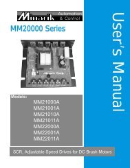
Model 200-0386A<br />
Switching Logic Board<br />
User’s Manual<br />
For Use With Minarik<br />
Full-Wave Regenerative Drives
Copyright © 2002 by<br />
Minarik Corporation<br />
All rights reserved. No part of this manual may be reproduced or transmitted in any<br />
form without written permission from Minarik Corporation. The information and<br />
technical data in this manual are subject to change without notice. Minarik<br />
Corporation and its Divisions make no warranty of any kind with respect to this<br />
material, including, but not limited to, the implied warranties of its merchantability<br />
and fitness for a given purpose. Minarik Corporation and its Divisions assume no<br />
responsibility for any errors that may appear in this manual and make no<br />
commitment to update or keep current the information in this manual. MVD062802<br />
Printed in the United States of America.
Safety Warnings<br />
SHOCK<br />
HAZARD<br />
AVOID<br />
HEAT<br />
KEE<br />
DR<br />
OID<br />
ATION<br />
• Have a qualified electrical maintenance technician install,<br />
adjust, and service this equipment. Follow the National<br />
Electrical Code and all other applicable electrical and<br />
safety codes, including the provisions of the Occupational<br />
Safety and Health Act (OSHA) when installing equipment.<br />
• Reduce the chance of an electrical fire, shock, or explosion<br />
by proper grounding, over current protection, thermal<br />
protection, and enclosure. Follow sound maintenance<br />
procedures.<br />
• It is possible for a drive to run at full speed as a result of a<br />
component failure. Install a master switch in the AC line for<br />
stopping the drive in an emergency.<br />
• When the switching logic board is connected to a variable<br />
speed regenerative drive it is isolated from earth ground.<br />
Circuit potentials are at 115 VAC or 230 VAC above earth<br />
ground. Avoid direct contact with the printed circuit board or<br />
with circuit elements to prevent the risk of serious injury or<br />
fatality. Use a non-metallic screwdriver for any necessary<br />
adjustments.
ii<br />
Contents<br />
Safety Warnings<br />
i<br />
Specifications 1<br />
Dimensions 2<br />
General Information 3<br />
Installation 4<br />
Mounting the Logic Board . . . . . . . . . . . . . . . . . . . . . . . . . . . . . . . . . . . . .4<br />
Wiring . . . . . . . . . . . . . . . . . . . . . . . . . . . . . . . . . . . . . . . . . . . . . . . . . . . .5<br />
Screw terminal block . . . . . . . . . . . . . . . . . . . . . . . . . . . . . . . . . . . . . . . . .5<br />
Speed adjust potentiometer . . . . . . . . . . . . . . . . . . . . . . . . . . . . . . . . . . . .6<br />
Shielding Guidelines . . . . . . . . . . . . . . . . . . . . . . . . . . . . . . . . . . . . . . . . . .9<br />
Modes of Operation 10<br />
Pushbutton switches . . . . . . . . . . . . . . . . . . . . . . . . . . . . . . . . . . . . . . . .11<br />
Limit switches . . . . . . . . . . . . . . . . . . . . . . . . . . . . . . . . . . . . . . . . . . . . .11<br />
Foot pedals . . . . . . . . . . . . . . . . . . . . . . . . . . . . . . . . . . . . . . . . . . . . . . .11<br />
DIP switches . . . . . . . . . . . . . . . . . . . . . . . . . . . . . . . . . . . . . . . . . . . . . .11<br />
Pushbutton operation: FORWARD/STOP/REVERSE . . . . . . . . . . . . . . . .12<br />
Pushbutton operation: RUN/STOP . . . . . . . . . . . . . . . . . . . . . . . . . . . . .13<br />
Pushbutton operation: jog FORWARD/jog REVERSE . . . . . . . . . . . . . . .14<br />
Pushbutton operation: jog RUN . . . . . . . . . . . . . . . . . . . . . . . . . . . . . . . .15<br />
Limit switch operation: no automatic reversing . . . . . . . . . . . . . . . . . . . . .16<br />
Limit switch operation: FORWARD/STOP/REVERSE, 1 Cycle . . . . . . . . .17<br />
Limit switch operation: automatic cycling . . . . . . . . . . . . . . . . . . . . . . . . .18<br />
Foot pedal operation: FORWARD/STOP/REVERSE . . . . . . . . . . . . . . . .20<br />
Foot pedal operation: RUN/STOP . . . . . . . . . . . . . . . . . . . . . . . . . . . . . .21
iii<br />
Connection to Minarik Regenerative Drives 22<br />
Unconditional Warranty<br />
inside back cover<br />
Illustrations<br />
Figure 1. Model 200-0386A Switching Logic Board Layout and Dimensions 2<br />
Figure 2. Screw Terminal Block 5<br />
Figure 3. Speed Adjust Potentiometer 6<br />
Figure 4. Single Speed Potentiometer Connections 7<br />
Figure 5. Two Speed Potentiometer Connection 8<br />
Figure 6. Pushbutton Operation: FWD/STOP/REV 12<br />
Figure 7. Pushbutton Operation: RUN/STOP 13<br />
Figure 8. Pushbutton Operation: jog Forward/jog Reverse 14<br />
Figure 9. Pushbutton Operation: jog RUN 15<br />
Figure 10. Limit switch operation: no automatic reversing 16<br />
Figure 11. Limit Switch Operation: FWD/STOP/REV, 1 cycle 17<br />
Figure 12. Limit Switch Operation: automatic cycling 19<br />
Figure 13. Foot pedal operation: FORWARD/STOP/REVERSE 20<br />
Figure 14 Foot pedal operation: RUN/STOP 21<br />
Figure 15. Connection diagram: Switching Logic Board (200-0386A) to<br />
RG100UC/RG200UC 22<br />
Figure 16. Connection diagram: Switching Logic Board (200-0386A) to<br />
RG300UA/RG310UA/RG400UA 23<br />
Figure 17. Connection diagram: Switching Logic Board (200-0386A) to<br />
RG500UA/RG510UA 24
iv<br />
Illustrations (cont.)<br />
Figure 18. Connection diagram: Switching Logic Board (200-0386A)<br />
to RG5500U 25<br />
Figure 19. Connection diagram: Switching Logic Board (200-0386A)<br />
to MRG30U/MMRG31U/MMRG40U 26<br />
Figure 20. Connection diagram: Switching Logic Board (200-0386A)<br />
to MMRGD03/MMRGD10 27<br />
Figure 21. Connection diagram: Switching Logic Board (200-0386A)<br />
to RG60U 28<br />
Figure 22. TTL Logic Input 29<br />
Figure 23. NPN Open Collector Input 30<br />
Figure 24. Contact Input 31
1<br />
Specifications<br />
Input Power<br />
+15 VDC @ 20 mA<br />
-15 VDC @ 1.5 mA<br />
Acceptable Input Devices<br />
Dry Contacts<br />
Current-Sinking Open Collectors<br />
TTL Logic Devices<br />
Number of Switching Modes Four (4)<br />
Speed adjust potentiometer<br />
10 K Ohms<br />
Maximum Reference Voltage to Drive<br />
±15 VDC<br />
Ambient Operating Temperature Range 10°C - 40°C<br />
Weight<br />
0.2 lbs<br />
Note: This switching logic board is specifically designed to operate with Minarik<br />
control models RG100UC, RG200UC, RG300U, RG400U, RG500U,<br />
RG5500U, and RG60U. Consult factory before attempting to use with other<br />
models.
2<br />
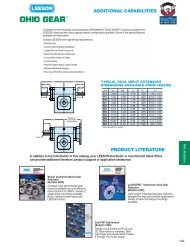
Dimensions<br />
TB502<br />
TB501<br />
8<br />
9<br />
10 11<br />
POWER<br />
IL501<br />
6<br />
IC501<br />
7<br />
12<br />
13<br />
14 15 16<br />
K501<br />
IC502<br />
2 3 4 5<br />
3.10 [79]<br />
17 18<br />
K<br />
1<br />
0.20 [5]<br />
0.87 [22]<br />
2.49 [63]<br />
3.45 [88]<br />
MOUNTING HOLES<br />
0.19 [5] - 4 PLACES<br />
1.0525"<br />
Figure 1. Model 200-0386A Switching Logic Board Layout<br />
and Dimensions
3<br />
General Information<br />
<br />
Caution<br />
Regenerative braking imposes very high stress on the<br />
rotating components of the drive train. It is very important<br />
that these deceleration forces be considered before selecting<br />
a drive system that applies regenerative braking to a<br />
gearmotor or other gearbox.<br />
Minarik Corporation’s model 200-0386A provides the logic<br />
interface between the regenerative drive and pushbutton<br />
stations, foot switches, or programmable controls. It accepts<br />
dry contact mechanical closures, current-sinking open<br />
collectors, and TTL logic devices.<br />
The limit switch logic board has four operating modes, which<br />
can be configured nine different ways. Select the one that<br />
fits your application and follow the wiring and DIP switch<br />
instructions for that configuration.<br />
The speed adjust potentiometer (10K ohms, 2 watts) is<br />
wired through the logic board (200-0386A) module, rather<br />
than directly to the regenerative drive. Use either one<br />
potentiometer for both forward and reverse speeds (Figure 4,<br />
page 7) or if different speeds are required in each direction –<br />
one potentiometer for forward and one potentiometer for<br />
reverse speed settings (Figure 5, page 8).
4<br />
Installation<br />
Mounting the Logic Board<br />
Logic board components are sensitive to electrostatic fields.<br />
Avoid contact with the circuit board directly.<br />
Protect the logic board from dirt, moisture, and accidental<br />
contact. Provide sufficient room for access to the terminal<br />
block.<br />
Mount the logic board away from other heat sources. Operate<br />
within the specified ambient operating temperature range.<br />
The operating temperature range for the 200-0386A is 10°C<br />
through 40° C.<br />
Prevent loose connections by avoiding excessive vibration of<br />
the logic board.<br />
Mount the logic board in either a horizontal or vertical plane<br />
using the four 0.19 inch [5 mm] mounting holes located on<br />
the board.
Installation<br />
5<br />
Wiring<br />
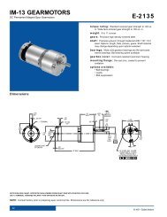
Screw terminal block<br />
Connections to Minarik’s 200-0386A logic board are made to<br />
a screw terminal block. There are two screw terminal blocks<br />
on the board. The large one is shown in Figure 2. The<br />
smaller screw terminal block has a similar connection style to<br />
the one shown.<br />
Using a screwdriver, turn the terminal block screw counterclockwise<br />
to open the wire clamp. Insert stripped wire into<br />
the wire clamp. Turn the terminal block screw clockwise to<br />
clamp the wire.<br />
TERMINAL BLOCK<br />
SCREW<br />
WIRE CLAMP<br />
Figure 2. Screw Terminal Block
6 Installation<br />
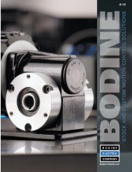
Speed adjust potentiometer<br />
<br />
Warning<br />
Be sure that the potentiometer tabs do not make contact with<br />
the potentiometer enclosure. Grounding the input will cause<br />
damage to the regenerative drive.<br />
Install the circular insulating disk between the panel and the<br />
10K ohm speed adjust pot. Mount the speed adjust pot<br />
through a 0.38 inch (10mm) hole with the hardware provided<br />
(Figure 3). Twist the speed adjust pot wire to avoid picking up<br />
unwanted electrical noise. If potentiometer leads are longer<br />
than 18 inch (457mm), use shielded cable. Logic lines of this<br />
length act as an antenna and can pick up noise from the<br />
drive components, noise from other devices or other ground<br />
wires, or voltage from power lines that can cause erratic<br />
operation. The 200-0386A does not include this pot.<br />
MOUNT THROUGH A 0.38 IN. (10 MM) HOLE<br />
CW<br />
WIPER<br />
W<br />
NUT<br />
STAR<br />
WASHER<br />
SPEED ADJUST<br />
POTENTIOMETER<br />
PANEL<br />
INSULATING DISK<br />
Figure 3. Speed Adjust Potentiometer
Installation<br />
7<br />
It may be necessary to earth ground the shielded cable. If<br />
noise is produced by devices other that the drive, ground the<br />
shield at the drive end. If noise is generated by a device on<br />
the drive, ground the shield at the end away from the drive.<br />
Do not ground both ends of the shield.<br />
The following diagrams show the potentiometer connections<br />
to terminal block 2 (TB2).<br />
Use Figure 4 when a single speed is desired in both the<br />
forward and reverse directions.<br />
Use Figure 5 when one speed is desired in the forward<br />
direction, and a different speed is desired in the reverse<br />
direction.<br />
15<br />
14<br />
13<br />
12<br />
11<br />
10<br />
9<br />
8<br />
CW<br />
10K OHM<br />
SPEED ADJUST<br />
POTENTIOMETER<br />
Figure 4. Single Speed Potentiometer Connections
8<br />
Installation<br />
15<br />
14<br />
13<br />
12<br />
11<br />
10<br />
9<br />
8<br />
CW<br />
CW<br />
Figure 5. Two Speed Potentiometer Connection
Installation<br />
9<br />
Shielding Guidelines<br />
<br />
Warning<br />
Under no circumstances should power and logic leads be<br />
bundled together. Induced voltage can cause unpredicatble<br />
behavior in any electronic device, including motor controls.<br />
As a general rule, Minarik recommends shielding of all<br />
conductors.<br />
If it is not practical to shield power conductors, Minarik<br />
recommends shielding all logic-level leads. If shielding logic<br />
leads is not practical, the user should twist all logic leads with<br />
themselves to minimize induced noise.<br />
It may be necessary to earth ground the shielded cable. If<br />
noise is produced by devices other than the drive, ground the<br />
shielf at the drive end. If noise is generated by a device on<br />
the drive, ground the sheild at the end away from the drive.<br />
Do not ground both ends of the shield.<br />
If the drive continues to pick up noise after grounding the<br />
shield, it may be necessary to add AC line filtering devices, or<br />
to mount the drive in a less noisy environment.
10<br />
Modes of Operation<br />
The limit switch logic board has four (4) different modes of<br />
operation which can be configured into nine (9) difference<br />
connections. They are as follows:<br />
1) FORWARD/STOP/REVERSE<br />
• Pushbutton Operation<br />
• Limit Switch Operation<br />
• Foot Pedal Operation<br />
2) RUN/STOP<br />
• Pushbutton Operation<br />
• Foot Pedal Operation<br />
• Limit Switch Operation (no automatic reversing)<br />
3) jog FORWARD/jog REVERSE<br />
• Pushbutton Operation<br />
4) jog RUN<br />
• Pushbutton Operation<br />
• Limit Switch Operation
Modes of Operation<br />
11<br />
Pushbutton switches<br />
Pushbutton switches are momentary operated type. RUN,<br />
FWD, and REV switches are normally open. STOP switches<br />
are normally closed.<br />
Limit switches<br />
Limit switches are single pole, single throw, normally closed.<br />
Foot pedals<br />
Foot pedals are single pole, single throw, normally open.<br />
DIP switches<br />
Use a small screwdriver to change DIP switch settings. The<br />
arrow on the dip switch box indicates the ON position.
12 Modes of Operation<br />
Pushbutton operation: FORWARD/STOP/REVERSE<br />
In this mode the appropriate pushbutton initiates travel. The<br />
motor is reversed by pressing the opposite direction<br />
pushbutton. The stop pushbutton will regeneratively brake the<br />
motor.<br />
OFF OFF<br />
O<br />
N<br />
1 2 3 4 5 6 7<br />
TB501<br />
FWD<br />
REV<br />
STOP<br />
JUMPER<br />
Figure 6. Pushbutton Operation: FWD/STOP/REV
Modes of Operation<br />
13<br />
Pushbutton operation: RUN/STOP<br />
In this mode the RUN pushbutton is actuated to start the<br />
motor. The motor will continue to run until the STOP<br />
pushbutton is depressed. This mode does not allow<br />
reversing. If the motor runs in the wrong direction, shut down<br />
the system and reverse the armature connections to the<br />
regenerative drive.<br />
OFF OFF<br />
O<br />
N<br />
1 2 3 4 5 6 7<br />
TB501<br />
RUN<br />
STOP<br />
JUMPER<br />
Figure 7. Pushbutton Operation: RUN/STOP
14 Modes of Operation<br />
Pushbutton operation: jog FORWARD/jog REVERSE<br />
In this mode the motor turns only when the forward or<br />
reverse pushbutton is being depressed. To reverse the motor,<br />
first release the activated pushbutton to regeneratively brake<br />
the motor. Then push the opposite direction pushbutton.<br />
ON<br />
ON<br />
O<br />
N<br />
1 2 3 4 5 6 7<br />
TB501<br />
FWD<br />
REV<br />
JUMPER<br />
JUMPER<br />
Figure 8. Pushbutton Operation: jog Forward/jog Reverse
Modes of Operation<br />
15<br />
Pushbutton operation: jog RUN<br />
In this mode the motor turns only as long as the RUN<br />
pushbutton is depressed. When the pushbutton is released<br />
the drive will regeneratively brake the motor. If the motor runs<br />
in the wrong direction, shut down the system and reverse the<br />
armature connections to the regenerative drive.<br />
ON<br />
ON<br />
O<br />
N<br />
1 2 3 4 5 6 7<br />
TB501<br />
RUN<br />
JUMPER<br />
JUMPER<br />
Figure 9. Pushbutton Operation: jog RUN
16 Modes of Operation<br />
Limit switch operation: no automatic reversing<br />
In this mode activating the appropriate pushbutton will initiate<br />
travel. The motor will regeneratively brake when the<br />
corresponding limit switch is actuated (opened) or when the<br />
STOP pushbutton is depressed. If travel is interrupted by<br />
STOP before the limit switch is reached, it can be resumed<br />
by pressing the appropriate direction pushbutton.<br />
OFF OFF<br />
O<br />
N<br />
1 2 3 4 5 6 7<br />
TB501<br />
REV<br />
FWD<br />
REV<br />
STOP<br />
FWD<br />
Figure 10. Limit switch operation: no automatic reversing
Modes of Operation<br />
17<br />
Limit switch operation: FORWARD/STOP/REVERSE,<br />
1 Cycle<br />
In this single-cycle mode the motor automatically returns to<br />
the REV limit switch location. It normally begins at that site<br />
with the actuation of the FWD pushbutton. If the starting<br />
position is not at the FWD limit switch, press FWD to<br />
complete the balance of the automatic FWD/STOP/REV cycle<br />
or press REV to complete the REV portion of the cycle.<br />
ON OFF<br />
O<br />
N<br />
1 2 3 4 5 6 7<br />
TB501<br />
REV<br />
FWD<br />
REV<br />
STOP<br />
FWD<br />
Figure 11. Limit Switch Operation: FWD/STOP/REV, 1 cycle
18 Modes of Operation<br />
Limit switch operation: automatic cycling<br />
In this mode the motor will continuously cycle the load<br />
between the FWD and REV limit switches. To stop the cycling<br />
process, press the STOP pushbutton. Re-starting the cycle is<br />
dependent upon the position of the machine when stopped:<br />
• If stopping occurs with the FWD limit switch activated, the<br />
REV pushbutton must be pressed to re-start.<br />
• If stopping occurs with the REV limit switch activated, the<br />
FWD pushbutton must be pressed to re-start the cycle.<br />
• If stopping occurs between the FWD and REV limit<br />
switches, either pushbutton may be pressed to re-start the<br />
cycle.
Modes of Operation<br />
19<br />
OFF ON<br />
O<br />
N<br />
1 2 3 4 5 6 7<br />
TB501<br />
REV<br />
FWD<br />
REV<br />
STOP<br />
FWD<br />
Figure 12. Limit Switch Operation: automatic cycling
20 Modes of Operation<br />
Foot pedal operation: FORWARD/STOP/REVERSE<br />
In this mode the motor runs as long as a pedal is depressed.<br />
When the pedal is released the drive will regeneratively brake<br />
the motor. When reversing the direction of travel it is<br />
necessary to release one pedal before depressing the other.<br />
ON<br />
ON<br />
O<br />
N<br />
1 2 3 4 5 6 7<br />
TB501<br />
FWD<br />
REV<br />
JUMPER<br />
JUMPER<br />
Figure 13. Foot pedal operation:<br />
FORWARD/STOP/REVERSE
Modes of Operation<br />
21<br />
Foot pedal operation: RUN/STOP<br />
In this mode the motor runs as long as the pedal is<br />
depressed. Release the pedal and the drive will<br />
regeneratively brake the motor. If the motor runs in the wrong<br />
direction, shut down the system and reverse the armature<br />
connections to the regenerative drive.<br />
ON<br />
ON<br />
O<br />
N<br />
1 2 3 4 5 6 7<br />
TB501<br />
RUN<br />
JUMPER<br />
JUMPER<br />
Figure 14 Foot pedal operation: RUN/STOP
22<br />
Connection to Minarik<br />
Regenerative Drives<br />
K501<br />
K502<br />
IC502<br />
1<br />
2<br />
P501<br />
K501<br />
P502<br />
P509<br />
C501<br />
P503<br />
P510<br />
IC501<br />
C502<br />
P504<br />
IC502<br />
TB502<br />
2<br />
13<br />
14 15 16<br />
17 18<br />
1 2 3<br />
4<br />
5 6 7 8<br />
9<br />
200-0386A RG100UC/RG200UC<br />
Figure 15. Connection diagram: Switching Logic Board<br />
(200-0386A) to RG100UC/RG200UC
Connection to Minarik Regenerative Drives<br />
23<br />
02<br />
GND<br />
1<br />
2 3<br />
F1<br />
T505<br />
F2<br />
A2<br />
K502<br />
IC502<br />
C504<br />
C502<br />
C503<br />
TB501<br />
A1<br />
2<br />
1<br />
C511<br />
IC502<br />
IC501<br />
C505<br />
+<br />
+<br />
INHIBIT<br />
TB502<br />
14 15 16<br />
17 18<br />
S3<br />
S2<br />
S1 S0 RB1 RB2 -15 +15<br />
200-0386A RG300UA/RG310UA/<br />
RG400UA<br />
Figure 16. Connection diagram: Switching Logic Board<br />
(200-0386A) to RG300UA/RG310UA/RG400UA
24<br />
Connection to Minarik Regenerative Drives<br />
200-0386A RG500UA/RG510UA<br />
TB502<br />
C505<br />
3<br />
14<br />
15<br />
16<br />
17<br />
18<br />
S3<br />
S2 S1 S0 RB1 RB2 -15 +15 T1 T2<br />
Figure 17. Connection diagram: Switching Logic Board<br />
(200-0386A) to RG500UA/RG510UA
Connection to Minarik Regenerative Drives<br />
25<br />
200-0386A RG5500U<br />
A2 A1<br />
DISABLE/ENABLE<br />
CFVS<br />
1-5<br />
4-20<br />
10-50<br />
SW505<br />
TB502<br />
C503<br />
C516<br />
IC502<br />
4 15 16 17 18<br />
TB501<br />
L1 L2<br />
CS S3 S2 S1 SO TP -15<br />
S1<br />
S2<br />
S3<br />
S0<br />
Figure 18. Connection diagram: Switching Logic Board<br />
(200-0386A) to RG5500U
26 Connections to Minarik Regenerative Drives<br />
200-0386A<br />
MMRG30U/MMRG31U/<br />
MMRG40U<br />
S1<br />
8<br />
18<br />
DS5<br />
1<br />
K502<br />
17<br />
60HZ<br />
PL2<br />
2<br />
15<br />
16<br />
K501<br />
14<br />
13<br />
DC VOLTAGE<br />
DC VOLTAGE<br />
S2<br />
9<br />
11<br />
SW501<br />
MMRG<br />
PL1<br />
12<br />
DC VOLTAGE<br />
10<br />
TB502<br />
DC VOLTAGE<br />
+15V -15V<br />
T501<br />
SO501<br />
COMMON<br />
S0<br />
IC501<br />
Figure 19. Connection diagram: Switching Logic Board<br />
(200-0386A) to MRG30U/MMRG31U/MMRG40U
Connections to Minarik Regenerative Drives<br />
27<br />
200-0386A MMRGD03/MMRGD10<br />
POWER<br />
S0<br />
IL503 IL504<br />
IL505<br />
IC501<br />
K502<br />
K501<br />
8 9 10 11 12 13 14 15 16 17 18<br />
C502<br />
C501<br />
SW502<br />
IC502<br />
SW501<br />
115 230<br />
230 115<br />
P501 P502 P503 P504<br />
SW503<br />
T501<br />
S1 REV FWD<br />
S2<br />
S3<br />
+15V<br />
-15V<br />
RB4<br />
RB3<br />
RB2<br />
RB1/COM<br />
TACHO<br />
FEEDBACK<br />
TACH ARM<br />
SO501<br />
IC501<br />
PL2<br />
ARMATUR<br />
180 90<br />
TB502<br />
FWD<br />
ACC<br />
REV<br />
ACC<br />
FWD<br />
TQ<br />
REV<br />
TQ<br />
P508<br />
P507<br />
P506<br />
P505<br />
MAX MIN IR<br />
SPD SPD COMP<br />
TACH<br />
Figure 20. Connection diagram: Switching Logic Board<br />
(200-0386A) to MMRGD03/MMRGD10
K<br />
28<br />
Connections to Minarik Regenerative Drives<br />
2 3<br />
1<br />
REV<br />
C50<br />
IC502<br />
L2<br />
L1<br />
X<br />
INVERT<br />
INHIBIT<br />
MP<br />
INVERT<br />
ENABLE<br />
LIMIT<br />
FWD REV<br />
D<br />
IL501 IL502<br />
TB502<br />
Y501<br />
JP502<br />
C503<br />
IC501<br />
IC504<br />
TB503<br />
ENABLE<br />
C5<br />
IL503<br />
K501<br />
POWER<br />
TACH<br />
T2<br />
T1<br />
RB1<br />
RB2<br />
-15V<br />
+15V<br />
S3<br />
S2<br />
S1<br />
S0<br />
3<br />
14 15 16<br />
17 18<br />
TB501<br />
T501<br />
S3<br />
S2<br />
S1<br />
S0<br />
200-0386A RG60U<br />
Figure 21. Connection diagram: Switching Logic Board<br />
(200-0386A) to RG60U
TB502<br />
NOTE: TTL GATES MAY REQUIRE<br />
PULL-UP RESISTORS<br />
FWD PB<br />
N.O.<br />
REV PB<br />
N.O.<br />
TTL GATES<br />
STOP PB<br />
N.C.<br />
COMMON<br />
FWD LS<br />
N.C.<br />
REV LS<br />
N.C.<br />
TTL LOGIC +5<br />
R<br />
2.2K<br />
TB501<br />
1<br />
2<br />
3<br />
4<br />
5<br />
6<br />
7<br />
200-0386A<br />
SWITCHING<br />
LOGIC BOARD<br />
TB502<br />
18<br />
17<br />
16<br />
15<br />
14<br />
13<br />
12<br />
11<br />
10<br />
Figure 22. TTL Logic Input<br />
9<br />
8<br />
(RB1/COM)<br />
(+15)<br />
(S2)<br />
(-15)<br />
JUMPER<br />
REV<br />
CW<br />
14<br />
13<br />
12<br />
11<br />
10<br />
9<br />
8<br />
FWD<br />
CW<br />
INDEPENDENT<br />
FWD & REV SPEED<br />
CONNECTIONS SHOWN<br />
CAUTION!<br />
TTL LOGIC MUST BE ISOLATED FROM THE AC LINE.<br />
CW<br />
JUMPERS<br />
SINGLE SPEED<br />
FOR FWD & REV<br />
CONNECTIONS SHOWN<br />
Connections to Minarik Regenerative Drives<br />
29
TB502<br />
30<br />
BASE CURRENT<br />
LIMITING RESISTORS<br />
FWD PB<br />
R<br />
N.O.<br />
+BASE VOLTAGE<br />
REV PB<br />
R<br />
N.O.<br />
+BASE VOLTAGE<br />
STOP PB<br />
R<br />
N.C.<br />
+BASE VOLTAGE<br />
COMMON<br />
FWD LS<br />
N.C.<br />
REV LS<br />
N.C.<br />
TB501<br />
1<br />
2<br />
3<br />
4<br />
5<br />
6<br />
7<br />
200-0386A<br />
SWITCHING<br />
LOGIC BOARD<br />
TB502<br />
18<br />
17<br />
16<br />
15<br />
14<br />
13<br />
12<br />
11<br />
10<br />
9<br />
8<br />
(RB1/COM)<br />
(+15)<br />
(S2)<br />
(-15)<br />
JUMPER<br />
REV<br />
CW<br />
14<br />
13<br />
12<br />
11<br />
10<br />
9<br />
8<br />
FWD<br />
CW<br />
INDEPENDENT<br />
FWD & REV SPEED<br />
CONNECTIONS SHOWN<br />
CW<br />
JUMPERS<br />
SINGLE SPEED<br />
FOR FWD & REV<br />
CONNECTIONS SHOWN<br />
Connections to Minarik Regenerative Drives<br />
CAUTION!<br />
NPN TRANSISTOR SUPPLY VOLTAGE<br />
MUST BE ISOLATED FROM THE AC LINE.<br />
Figure 23. NPN Open Collector Input
TB502<br />
FWD PB<br />
N.O.<br />
REV PB<br />
N.O.<br />
STOP PB<br />
N.C.<br />
FWD LS<br />
N.C.<br />
REV LS<br />
N.C.<br />
TB501<br />
1<br />
2<br />
3<br />
4<br />
5<br />
6<br />
7<br />
200-0386A<br />
SWITCHING<br />
LOGIC BOARD<br />
TB502<br />
18<br />
17<br />
16<br />
15<br />
14<br />
13<br />
12<br />
11<br />
10<br />
9<br />
8<br />
(RB1/COM)<br />
(+15)<br />
(S2)<br />
(-15)<br />
JUMPER<br />
REV<br />
CW<br />
14<br />
13<br />
12<br />
11<br />
10<br />
9<br />
8<br />
FWD<br />
CW<br />
INDEPENDENT<br />
FWD & REV SPEED<br />
CONNECTIONS SHOWN<br />
CW<br />
JUMPERS<br />
SINGLE SPEED<br />
FOR FWD & REV<br />
CONNECTIONS SHOWN<br />
Connections to Minarik Regenerative Drives<br />
Figure 24. Contact Input<br />
31
32<br />
NOTES
Unconditional Warranty<br />
A. Warranty<br />
Minarik Corporation (referred to as "the Corporation") warrants that its products will<br />
be free from defects in workmanship and material for twelve (12) months or 3,000<br />
hours, whichever comes first, from date of manufacture thereof. Within this warranty<br />
period, the Corporation will repair or replace, at its sole discretion, such products that<br />
are returned to Minarik Corporation, 901 East Thompson Avenue, Glendale, CA<br />
91201-2011 USA.<br />
This warranty applies only to standard catalog products, and does not apply to<br />
specials. Any returns for special controls will be evaluated on a case-by-case basis.<br />
The Corporation is not responsible for removal, installation, or any other incidental<br />
expenses incurred in shipping the product to and from the repair point.<br />
B. Disclaimer<br />
The provisions of Paragraph A are the Corporation's sole obligation and exclude all<br />
other warranties of merchantability for use, express or implied. The Corporation<br />
further disclaims any responsibility whatsoever to the customer or to any other<br />
person for injury to the person or damage or loss of property of value caused by any<br />
product that has been subject to misuse, negligence, or accident, or misapplied or<br />
modified by unauthorized persons or improperly installed.<br />
C. Limitations of Liability<br />
In the event of any claim for breach of any of the Corporation's obligations, whether<br />
express or implied, and particularly of any other claim or breech of warranty<br />
contained in Paragraph A, or of any other warranties, express or implied, or claim of<br />
liability that might, despite Paragraph B, be decided against the Corporation by<br />
lawful authority, the Corporation shall under no circumstances be liable for any<br />
consequential damages, losses, or expense arising in connection with the use of, or<br />
inability to use, the Corporation's product for any purpose whatsoever.<br />
An adjustment made under warranty does not void the warranty, nor does it imply an<br />
extension of the original 12-month warranty period. Products serviced and/or parts<br />
replaced on a no-charge basis during the warranty period carry the unexpired<br />
portion of the original warranty only.<br />
If for any reason any of the foregoing provisions shall be ineffective, the<br />
Corporation's liability for damages arising out of its manufacture or sale of<br />
equipment, or use thereof, whether such liability is based on warranty, contract,<br />
negligence, strict liability in tort, or otherwise, shall not in any event exceed the full<br />
purchase price of such equipment.<br />
Any action against the Corporation based upon any liability or obligation arising<br />
hereunder or under any law applicable to the sale of equipment or the use thereof,<br />
must be commenced within one year after the cause of such action arises.
901 East Thompson Avenue<br />
Glendale, California 91201-2011<br />
Phone: (818) 502-1528<br />
Fax: (818) 502-0716<br />
www.minarikcorp.com<br />
Document number 250–0222, Revision 2<br />
Printed in the U.S.A – June 2002