Create successful ePaper yourself
Turn your PDF publications into a flip-book with our unique Google optimized e-Paper software.
INSTRUCTIONS FOR USE<br />
CIRCUIT - BREAKER<br />
<strong>ARION</strong> <strong>WL</strong><br />
OEZ servicing department ensures circuit breaker retrofit and completion of accessories.<br />
Installation, service and maintenance of the electrical equipment may be carried out by<br />
an authorized person only.<br />
Non-observance of this condition may result in loss of warranty!<br />
<strong>991061a</strong> Z00
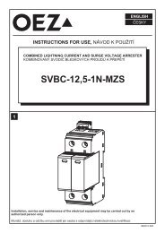
LIFTING BY CRANE<br />
Caution<br />
Do not place beaker<br />
on its rear side!<br />
!<br />
1 m<br />
><br />
Breaker Guide frame Breaker<br />
+<br />
guide frame<br />
max 12 mm<br />
1 m<br />
><br />
max 12 mm<br />
1)<br />
1 m<br />
><br />
max 12 mm<br />
1)<br />
Frame size/No. of poles<br />
Weight<br />
I / 3<br />
I / 4<br />
II / 3<br />
II / 4<br />
III / 3<br />
III / 4<br />
43 kg<br />
50 kg<br />
max. 64 kg<br />
max. 77 kg<br />
max. 90 kg<br />
max. 108 kg<br />
25 kg<br />
30 kg<br />
max. 45 kg<br />
max. 54 kg<br />
max. 70 kg<br />
max. 119 kg<br />
70 kg<br />
84 kg<br />
max. 113 kg<br />
max. 136 kg<br />
max. 166 kg<br />
max. 227 kg<br />
1)<br />
Hook cable above the label<br />
- 2 - <strong>991061a</strong> Z00
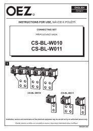
DESIGN<br />
Circuit - breaker<br />
28<br />
27<br />
26<br />
25<br />
24<br />
23<br />
22<br />
21<br />
20<br />
19<br />
18<br />
17<br />
16<br />
1<br />
2<br />
3<br />
4<br />
5<br />
6<br />
7<br />
8<br />
9<br />
10<br />
11<br />
12<br />
13<br />
14<br />
15<br />
1 Arc chute<br />
2 Carrying handle<br />
3 Identification tags<br />
4 Motor disconnect switch (option) or "Electrical ON" (option)<br />
5 Type label circuit - breaker<br />
6 Stored - energy indicator<br />
7 "Mechanical ON" button<br />
8 Ampere rating<br />
9 Racking pictogram<br />
10 Make-break operations counter (option)<br />
11 Spring charging lever<br />
12 Racking handle<br />
13 Draw - out unit transport shaft<br />
14 Options label<br />
15 Earthing terminal<br />
16 Position indicator<br />
17 Table for earth-fault protection<br />
18 Safety lock for racking handle (option)<br />
19 Mechanical release of racking hadndle<br />
20 Overcurrent release<br />
21 Rating plug<br />
22 "Mechanical OFF" button or<br />
"EMERG<strong>EN</strong>CY OFF" mushroom button (option)<br />
23 Ready-to-close indicator<br />
24 Breaker ON/OFF indicator<br />
25 Tripped indicator (Reset button)<br />
26 Locking device "Safe OFF" (option)<br />
27 Front panel<br />
28 Receptacle for auxiliary contacts<br />
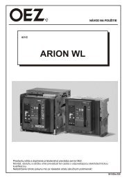
Guide frame<br />
1<br />
2<br />
1 Arc chute cover (option)<br />
2 Arcing openings<br />
18<br />
17<br />
16<br />
15<br />
14<br />
13<br />
12<br />
3<br />
4<br />
5<br />
6<br />
7<br />
8<br />
3 Hole for crane hook<br />
4 Shutter (option)<br />
5 Locking device shutter (option)<br />
6 Type label guide frame<br />
7 Disconnecting contacts<br />
8 Eartihng terminal 14<br />
9 Locking device guide rail<br />
10 Locking device to prevent racking with cubicle door open<br />
(option)<br />
11 Door interlocking guide frame (option)<br />
12 Guide rail<br />
13 Ampere rating cording by factory<br />
14 Sliding contact for circuit-breaker earthing (option)<br />
15 Option-related coding (option)<br />
16 Shutter operating device (option)<br />
17 Position signalling switch (option)<br />
18 Auxiliary disconnects (quantily according to equipment)<br />
11<br />
10<br />
9<br />
- 3 - <strong>991061a</strong> Z00
CONNECTING BARS<br />
Fixed-mounted breaker<br />
Horizontal connection<br />
(standard version)<br />
Front connection<br />
single hole double hole raw<br />
Vertical<br />
connection<br />
Guide frame<br />
Horizontal connection<br />
(standard version)<br />
Front connection<br />
single hole double hole raw<br />
Vertical<br />
connection<br />
Flange<br />
connection<br />
AUXILIARY CONDUCTORS<br />
Hand plug SIGUT<br />
(standard)<br />
Hand plug screwless terminal system<br />
(option)<br />
Auxiliary<br />
disconnects<br />
Receptacle<br />
Coding set<br />
For connection of auxiliary circuits, the circuit breakers of fixed version are equipped with manually plug-in<br />
terminal boards with coding pins, which eliminate misuse of the terminal boards in their connecting with<br />
the block of the citcuit breaker blade contacts.The contacts of auxiliary circuits of circuit breakers of<br />
withdrawable version are inserted automatically in circuit breaker moving into the frame.<br />
Conductors of auxiliary circuits are connected to terminal boards in two ways (see the figure).<br />
- 4 - <strong>991061a</strong> Z00
MINIMAL CROSS-SECTIONS OF MAIN LEADS<br />
Frame<br />
size<br />
Breaker<br />
type<br />
to<br />
<strong>ARION</strong><br />
<strong>WL</strong> 1110<br />
I II III<br />
<strong>ARION</strong><br />
<strong>WL</strong> 1112<br />
<strong>ARION</strong><br />
<strong>WL</strong> 1116<br />
<strong>ARION</strong><br />
<strong>WL</strong> 1208<br />
<strong>ARION</strong><br />
<strong>WL</strong> 1210<br />
<strong>ARION</strong><br />
<strong>WL</strong> 1212<br />
<strong>ARION</strong><br />
<strong>WL</strong> 1216<br />
<strong>ARION</strong><br />
<strong>WL</strong> 1220<br />
<strong>ARION</strong><br />
<strong>WL</strong> 1225<br />
<strong>ARION</strong><br />
<strong>WL</strong> 1232<br />
<strong>ARION</strong><br />
<strong>WL</strong> 1340<br />
<strong>ARION</strong><br />
<strong>WL</strong> 1350<br />
<strong>ARION</strong><br />
<strong>WL</strong> 1363<br />
Cu busbars<br />
bare<br />
[mm]<br />
Cu busbars<br />
black<br />
coated<br />
[mm]<br />
1 x<br />
60 x 10<br />
1 x<br />
60 x 10<br />
2 x<br />
40 x 10<br />
2 x<br />
40 x 10<br />
2 x<br />
50 x 10<br />
2 x<br />
50 x 10<br />
1 x<br />
50 x 10<br />
1 x<br />
50 x 10<br />
1 x<br />
60 x 10<br />
1 x<br />
60 x 10<br />
2 x<br />
40 x 10<br />
2 x<br />
40 x 10<br />
2 x<br />
50 x 10<br />
2 x<br />
50 x 10<br />
3 x<br />
50 x 10<br />
3 x<br />
50 x 10<br />
2 x<br />
100 x 10<br />
2 x<br />
100 x 10<br />
3 x<br />
100 x 10<br />
3 x<br />
100 x 10<br />
4 x<br />
100 x 10<br />
4 x<br />
100 x 10<br />
6 x<br />
100 x 10<br />
6 x<br />
100 x 10<br />
6 x<br />
100 x 10<br />
6 x<br />
100 x 10<br />
- 5 - <strong>991061a</strong> Z00
INSTALLATION<br />
MOUNTING DIM<strong>EN</strong>SIONS<br />
Fixed-mounted version:<br />
(standard version)<br />
d<br />
b<br />
a<br />
d<br />
e<br />
210<br />
230<br />
c<br />
127<br />
150<br />
Mounting area to remove the arc chutes<br />
Arcing space<br />
Cubicle door<br />
541,5<br />
461,5<br />
275<br />
150<br />
76 327,5<br />
106<br />
Frame size<br />
<strong>ARION</strong> <strong>WL</strong> I<br />
3 - pole<br />
a [mm] b [mm] c [mm] d [mm] e [mm]<br />
300 320 8 90 60<br />
4 - pole<br />
a [mm] b [mm] c [mm] d [mm] e [mm]<br />
390 410 8 90 60<br />
<strong>ARION</strong> <strong>WL</strong> II<br />
440 460<br />
8<br />
130<br />
90<br />
570 590<br />
8<br />
130<br />
90<br />
<strong>ARION</strong> <strong>WL</strong> III<br />
680 704<br />
10<br />
210<br />
130<br />
890 914<br />
10<br />
210<br />
130<br />
- 6 - <strong>991061a</strong> Z00
Withdrawable:<br />
(standard version)<br />
320<br />
d d e<br />
∅13,5<br />
b<br />
a<br />
f<br />
220<br />
367,5<br />
382,5<br />
c<br />
Test position<br />
Disconnected position<br />
76<br />
150<br />
275<br />
460<br />
327,5<br />
45<br />
45<br />
88,5<br />
121,5<br />
140,5<br />
Frame size<br />
<strong>ARION</strong> <strong>WL</strong> I<br />
3 - pole 4 - pole<br />
a [mm] b [mm] c [mm] d [mm] e [mm] f [mm] a [mm] b [mm] c [mm] d [mm] e [mm] f [mm]<br />
210 320 10 90 70 55 300 410 10 90 70 55<br />
<strong>ARION</strong> <strong>WL</strong> II<br />
350 460<br />
10<br />
130<br />
100<br />
55<br />
480 590<br />
10<br />
130<br />
100<br />
55<br />
<strong>ARION</strong> <strong>WL</strong> III<br />
590 704<br />
10<br />
210<br />
142<br />
57<br />
800 914<br />
10<br />
210<br />
142<br />
57<br />
- 7 - <strong>991061a</strong> Z00
MOUNTING POSITION<br />
Fixing points<br />
Mounting on horizontal surface<br />
Non-removable nut<br />
4 bolts M8-8.8<br />
4 bolts M8-8.8+nuts+strain washers<br />
If several draw-out circuit-breakers are arranged<br />
one above the other in cubicles without compartment<br />
bases we recommend to use arc chute covers.<br />
!<br />
On<br />
CONNECTING THE MAIN CONDUCTORS<br />
4-pole circuit-breakers, the neutral conductor must always be connected<br />
all on the left. Otherwise this can cause malfunctions of the electronic<br />
overcurrent release.<br />
Cleaning the main conductor<br />
connection<br />
- 8 - <strong>991061a</strong> Z00
Cleaning the copper bars<br />
Steel-wire<br />
brush<br />
Remove swarf<br />
Bolt tight line-side bars<br />
BRACING THE MAIN CONDUCTORS<br />
Rear connection<br />
Front connection<br />
support<br />
!When using front leads (withdrawable<br />
version), it is necessary to use supports.<br />
- 9 - <strong>991061a</strong> Z00
MANIPULATION WITH CIRCUIT-BREAKER<br />
Preparation of draw-out circuit breaker<br />
1. Unblocking racking handle / Withdrawing racking handle<br />
(see racking pictogram)<br />
1<br />
4<br />
Hold!<br />
2<br />
3<br />
2. Cranking the breaker into maintenance position<br />
5<br />
Stop<br />
Position<br />
indicator<br />
red<br />
blue<br />
green<br />
3. Inserting racking handle<br />
4. Removing the circuit-breaker<br />
from the guide frame<br />
1<br />
2<br />
3<br />
!Do not turn the crank handle beyond the stop! Otherwise the racking<br />
mechanism will be damaged.<br />
- 10 - <strong>991061a</strong> Z00
5. Mounting the guide frame into the cubicle<br />
see previous chapters<br />
6. Inserting the circuit-breaker in the guide frame<br />
1<br />
2<br />
click<br />
green<br />
1 Check breaker position indicator Ensure it shows DISCON.<br />
Otherwise the circuit-breaker cannot be inserted.<br />
2 Draw out guide rails.<br />
3<br />
4<br />
3 Place the circuit-breaker in the guide frame.<br />
4 Push it into disconnected position.<br />
7. Unblocking racking handle / Withdrawing racking handle<br />
1<br />
4<br />
Hold!<br />
2<br />
3<br />
5<br />
- 11 - <strong>991061a</strong> Z00
8. Racking circuit-breaker into connected position<br />
Stop<br />
Position indicator<br />
red<br />
blue<br />
green<br />
9. Inserting racking handle<br />
2<br />
1<br />
3<br />
4<br />
10. Close cubicle door<br />
!<br />
mechanism<br />
Do not turn the crank handle beyond the stop! Otherwise the racking<br />
will be damaged.<br />
- 12 - <strong>991061a</strong> Z00
11. Position of the breaker in the guide frame<br />
Diagram<br />
Position<br />
indicator<br />
Power<br />
circuit<br />
Auxiliary<br />
circuit<br />
Cubicle<br />
door Shutter *<br />
Maintenance<br />
position<br />
(1)<br />
(2)<br />
(4)<br />
green<br />
disconnected disconnected<br />
open<br />
closed<br />
Disconnected<br />
position<br />
(3)<br />
disconnected disconnected<br />
closed<br />
closed<br />
green<br />
Test<br />
position<br />
blue<br />
disconnected<br />
connected<br />
closed<br />
closed<br />
Connected<br />
position<br />
red<br />
connected<br />
connected<br />
closed<br />
open<br />
(1) Auxiliary circuit (2) Power circuit (3) Cubicle door (4) Shutter<br />
* only if it is installed<br />
- 13 - <strong>991061a</strong> Z00
COMMISSIONING<br />
CHECKLIST FOR COMMISSIONING<br />
Action required:<br />
Switch OFF circuit-breaker.<br />
Rack circuit-breaker into connected poition (only withdrawable version).<br />
Insert rating plug.<br />
Press red pin to reset (mechanical reclosing lockout).<br />
Set the overcurrent release to appropriate values.<br />
Apply auxiliary and control voltages.<br />
Insert racking handle (only withdrawable version).<br />
Charge storage spring.<br />
Close the cubicle door.<br />
Please ensure following:<br />
Under-voltage release.................................................................................... energized<br />
Shunt trip........................................................................................................ not energized<br />
Electrical closing lockout................................................................................ not energized<br />
Electrical interlocking of closing coil in the switch board control wiring.......... disabled<br />
Mutual mechanical interlock........................................................................... not effective<br />
Locking devices.............................................................................................. not activated<br />
Indications:<br />
CLOSING<br />
ON button<br />
Electrical ON<br />
or<br />
Indications:<br />
Without motor<br />
operating mechanism<br />
With motor operating<br />
mechanism after 10s<br />
The storage spring will be recharged by the motor operating<br />
!mechanism immediately after the breaker has closed.<br />
- 14 - <strong>991061a</strong> Z00
SWITCHING OFF<br />
ON button<br />
Indications:<br />
Without motor operating<br />
mechanism<br />
With motor operating<br />
mechanism after 10s<br />
TRIPPING BY OVERCURR<strong>EN</strong>T RELEASE<br />
Overcurrent trip:<br />
Tripped indicator<br />
Indications:<br />
Without motor operating<br />
mechanism<br />
With motor operating<br />
mechanism after 10s<br />
- 15 - <strong>991061a</strong> Z00
OVERCURR<strong>EN</strong>T RELEASE ETU25B<br />
Mechanical RESET<br />
for reclosing lockout<br />
Options:Safety lock,<br />
prevents accidentat<br />
reseting of the lock-out<br />
mechanism after a trip<br />
Indicator overcurrent<br />
release activated<br />
Indicator overload alarm<br />
Trip unit error indicator<br />
Rating plug<br />
Rotary coding switch<br />
long time delay<br />
pickup setting<br />
Rotary coding<br />
switch short time<br />
delay pickup setting<br />
Fixed<br />
instantaneous<br />
pickup<br />
Query button<br />
Test button<br />
Trip cause indicator *<br />
Rotary coding switch<br />
short time delay setting<br />
Sealing eyelet<br />
Clear button<br />
Test connector<br />
* The trip cause is stored internally for at least two days, if the overcurrent release had been activated<br />
for at least 10 min before tripping.<br />
- 16 - <strong>991061a</strong> Z00
Overcurrent protection settings<br />
Adjust parameters only when the circuit-breaker is switched off. If the<br />
parameters are modified with the circuit-breaker switched on, this can<br />
!trip the circuit-breaker unintentionally.<br />
All parameters are adjusted with rotary coding switches.<br />
3 x 0,5<br />
The value 0,1 is set<br />
if the rotary switch is<br />
positioned in this zone.<br />
Protective functions<br />
- overload protection (L-tripping)<br />
- short-time-delay short-circuit tripping (S-tripping)<br />
- instantaneous short-circuit tripping (I-tripping)<br />
Operating characteristic<br />
L-tripping<br />
S-tripping<br />
I-tripping<br />
- 17 - <strong>991061a</strong> Z00
RE-STARTING A TRIPPED BREAKER<br />
1. Find trip cause<br />
2. Remedy causes<br />
indicators:<br />
check downstream load<br />
check overcurrent release settings<br />
overload in main<br />
conductor<br />
overload in neutral<br />
conductor<br />
short circuit:<br />
short-time-delay trip<br />
short circuit:<br />
instantaneous trip<br />
inspect panel<br />
check downstream load<br />
Earth-fault trip<br />
inspect panel<br />
check downstream load<br />
3. Inspect circuit-breaker<br />
check visually the circuit breaker for damage<br />
4. Clear trip cause<br />
5. Reset reclosing lock-out and tripped indicator<br />
manually<br />
or<br />
automatic<br />
- 18 - <strong>991061a</strong> Z00
click<br />
6. Indications<br />
Without motor operating<br />
mechanism<br />
With motor operating<br />
mechanism after 10s<br />
7. Charging the storage spring<br />
a) manually:<br />
9 x<br />
For charging the spring mechanism pull the handle and return the handle<br />
!completly up to the stop.<br />
b) by motor operating mechanism:<br />
Motor operating mechanism starts automatically after applying control voltage.<br />
The motor is automatically de-energized at the end of the charging operation.<br />
8. Closing<br />
see chapter Commissioning<br />
- 19 - <strong>991061a</strong> Z00
CIRCUIT DIAGRAMS<br />
TERMINAL ASSIGNM<strong>EN</strong>T ACCESSORY<br />
(Auxiliary switch S1, S2 = Standard)<br />
Internal wiring Terminals External wiring L / L+<br />
N / L-<br />
U c<br />
Remote reset bell alarm&<br />
tripped indicator F7<br />
G transformer S2<br />
G transformer S1<br />
N sensor S2<br />
N sensor S1<br />
ext. voltage transformer COM<br />
ext. voltage transformer L3<br />
ext. voltage transformer L2<br />
ext. voltage transformer L1<br />
0 V DC<br />
24 V DC<br />
CubicleBUS +<br />
CubicleBUS -<br />
e.g. transformer in the star point of<br />
the summation current transformer<br />
1200 A/1 A<br />
Short terminals if no N-sensor<br />
L1<br />
L2<br />
L3<br />
24 V DC input<br />
Termination resistor, if not external<br />
CubicleBus-module<br />
Not<br />
available<br />
with<br />
communication<br />
connection<br />
"F02".<br />
COM 15<br />
module<br />
is at position<br />
"-X7"<br />
trip signalling switch S24<br />
"Spring charged" signal S21<br />
Local electric close S10<br />
Signaling contact at the<br />
1st auxiliary release S22<br />
COM 15<br />
(Option F02)<br />
L / L+<br />
U s / U c<br />
Signaling contact at the<br />
2nd auxiliary release S23<br />
L / L+ Uc<br />
U c<br />
1st auxiliary release F1 "ST"<br />
N / L-<br />
S1 "NO"<br />
S1 "NC"<br />
Closing solenoid Y1<br />
"Ready to close" signal S20<br />
N / L-<br />
L / L+<br />
S2 "NO"<br />
S2 "NC"<br />
F4 only "quick OFF"<br />
2nd auxiliary release: F2 "ST". F3 "UVR"<br />
F4 "UVR td"<br />
S3 "NO" or S7 "NO"<br />
EMERG<strong>EN</strong>CY OFF or short terminals<br />
L / L+<br />
N / L-<br />
U c<br />
S3 "NC" or S7 "NO"<br />
S4 "NO" or S8 "NO"<br />
S4 "NC" or S8 "NO"<br />
Charging motor<br />
opt. motor main switch S12<br />
L / L+<br />
N / L-<br />
U c<br />
- 20 - <strong>991061a</strong> Z00
MAINT<strong>EN</strong>ANCE<br />
Contact assemblies need to be changed according their condition, but at least after:<br />
-10 000 Operations in FSI and FSII;<br />
-5 000 Operations in FSIII;<br />
-1 000 Operations in FSII and FSIII when used in 1000 V appliances<br />
The switchgear operator has to be determine inspection intervals depending on the breaker<br />
applications:<br />
-min. 1x per annum<br />
-after interruption of heavy loads<br />
-after trips by the overcurrent release (trip unit)<br />
-down stream connected non-automatic circuit breakers have to be inspected also<br />
During the inspection and/or after 1000 switching operations, the following items must be examined<br />
(max. operations see catalog):<br />
-arc chutes and contact systems<br />
-electrical and mechanical functionaliy of the breaker<br />
-mechanical on- / off-functionality<br />
-main and auxiliary circuits, function and connecting quality<br />
-plausibility control of trip unit settings and correction, if necessary<br />
If the breaker endurance is exhausted, then the breaker and old spare parts are to be disposed of,<br />
according to the effective legal regulations.<br />
Draw-Out guide frames with arc-chute covers installed, have to be replaced after no more than three<br />
schort-circuit interruptions of the circuit-breaker.<br />
The arc chutes and the contact system must be replaced depending upon their condition, but latest after<br />
10,000 switching operations.<br />
Depending on the circuit-breaker stress it may also be necessary to replace the operating system after<br />
10,000 switching operations.<br />
The attached CD contains more detailed operating instructions.<br />
Only materials which have low adverse environmental impact and which do not contain dangerous<br />
substances as specified in ROHS directive have been used in the product.<br />
- 21 - <strong>991061a</strong> Z00