FUSE SWITCH-DISCONNECTORS FOR CYLINDRICAL FUSE ...
FUSE SWITCH-DISCONNECTORS FOR CYLINDRICAL FUSE ...
FUSE SWITCH-DISCONNECTORS FOR CYLINDRICAL FUSE ...

Create successful ePaper yourself
Turn your PDF publications into a flip-book with our unique Google optimized e-Paper software.
Fuse switch-disconnectors and disconnectors for cylindrical fuse-links<br />
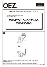
<strong>FUSE</strong> <strong>SWITCH</strong>-<strong>DISCONNECTORS</strong> <strong>FOR</strong> <strong>CYLINDRICAL</strong> <strong>FUSE</strong>-LINKS SIZE 14x51<br />
Fuse switch-disconnectors OPV14 are intended for cylindrical<br />
fuse-links PV14 size 14x51. They can safely switch off rated<br />
current and overcurrent up to 1.5 rated current and meet the<br />
requirements for safe disconnection. Inverse connection is<br />
permissible and it affects neither the technical parameters nor<br />
the safety of the operator.<br />
<br />
<br />
<br />
<br />
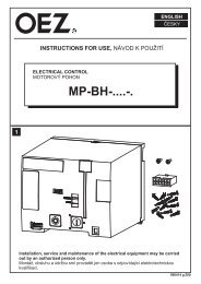
Switch-disconnectors OPV can be sealed in the closed<br />
state.<br />
The devices are designed as modular<br />
for 45 mm cutout in the switchboard.<br />
Optional light indication of fuse status.<br />
Mounted on 35 mm „U“ rail according to EN 60715<br />
or on the panel (steel rail recommended).<br />
Fuse switch-disconnectors<br />
Type<br />
Accessories<br />
Product<br />
code<br />
I n<br />
[A]<br />
Number of poles<br />
Weight<br />
[kg]<br />
Packing<br />
[pcs]<br />
OPV14/1 08249 1 0.120 12<br />
OPV14/N 08250 N 0.140 12<br />
OPV14/1N 08251 1+N 0.280 6<br />
OPV14/2 08252 63 A 2 0.260 6<br />
OPV14/3 08253 3 0.380 4<br />
OPV14/3N 08254 3+N 0.520 3<br />
OPV14/4 14851 4 0.520 3<br />
Product Weight Packing<br />
Description<br />
Type<br />
code [kg] [pcs]<br />
Light indication, operating voltage 100 ÷ 500 V a.c., d.c. S - OPV1422 8704 0.002 1<br />
Light indication, operating voltage 12 ÷ 48 V d.c., a.c.<br />
1<br />
S - OPV1422/48 11816 0.002<br />
(+ pole up)<br />
Light indication, operating voltage12 ÷ 48 V d.c., a.c.<br />
S - OPV1422/48PD 18235 0.002 1<br />
(+ pole down)<br />
3-pole busbar, cross-section 16 mm 2 ,<br />
rated operating voltage 415 V, max. operating voltage 500 V<br />
80 A at supply from the busbar end<br />
130 A at supply from the busbar middle, length 1 m<br />
3-pole busbar, cross-section 25 mm 2 ,<br />
rated operating voltage 415 V, max. operating voltage 500 V<br />
100 A at supply from the busbar end<br />
180 A at supply from the busbar middle, length 1 m<br />
3-pole busbar with tinned contacts for connection of<br />
Al conductor max. 25 mm 2 , busbar length 156 mm (6 poles)<br />
S-3L-27-1000/16 11864 0.240 1<br />
S-3L-27-1000/25 11865 0.240 1<br />
S-3L-27-156/16SN 11892 0.065 1<br />
Terminal extension for connection of Cu conductor of cross-section 2.5 ÷ 50 mm 2 AS-Al/Cu-16-50 18351 0.02 15<br />
and Al conductor of cross-section 16 ÷ 50 mm 2<br />
Connection block, enables power supply of busbars by conductors of cross-section<br />
up to 35 mm 2 , the use of the block extends the mounting with by additional n-poles<br />
Adapter for busbars with spacing 60 mm,<br />
busbar thickness 5 or 10 mm,<br />
busbar width 12 ÷ 30 mm, bottom cable outlet, max. current 63 A<br />
ES/35 S/G 00175 0.03 10<br />
GA-60/63/54-1x7,5 11883 0.560 1<br />
Parameters<br />
Standards<br />
IEC 60947-1, -3<br />
EN 60947-1, -3<br />
Rated operating voltage U e<br />
690 V<br />
Rated operating current I e<br />
63 A<br />
690 V a.c. AC-21B<br />
Utilization category<br />
250 V d.c. DC-21B<br />
700 V d.c. DC-20B<br />
Approval marks<br />
C4
Parameters<br />
Fuse switch-disconnectors and disconnectors for cylindrical fuse-links<br />
<strong>FUSE</strong> <strong>SWITCH</strong>-<strong>DISCONNECTORS</strong> <strong>FOR</strong> <strong>CYLINDRICAL</strong> <strong>FUSE</strong>-LINKS SIZE 14x51<br />
Rated thermal current with fuse-link I th<br />
63 A<br />
Rated frequency f n<br />
40 ÷ 60 Hz<br />
Rated insulation voltage U i<br />
800 V a.c.<br />
Rated conditional short-circuit current with<br />
fuse-links PV (rms)<br />
I cc<br />
690 V a.c. 110 kA<br />
Fuse-link size diameter x length diameter x length 14x51<br />
Max. rated current of the fuse-link I n<br />
63 A<br />
Max. power losses of the fuse-link 1) P v<br />
7 W<br />
Rated short-time withstand current I cw<br />
1s 1.6 kA<br />
Electrical durability (operating cycles) 300<br />
Mechanical durability (operating cycles) 1700<br />
Weight of one pole<br />
0.12 kg<br />
Degree of protection, cover closed<br />
IP20<br />
Degree of protection, cover open<br />
IP20<br />
Operating ambient temperature t - 25 ÷ + 55 °C<br />
Altitude above sea level max.<br />
2000 m<br />
Seismic resistance per VE ŠKODA<br />
3 g/8 ÷ 50 Hz<br />
Connection cross-section 0.5 ÷ 25 mm 2 (2 x 16 mm 2 )<br />
Torque<br />
2 Nm<br />
Rated impulse withstand voltage U imp<br />
4 kV<br />
Overvoltage category/Rated voltage I (II*)/ 690 V a.c., II (III*)/500 V a.c., III/400 V a.c.<br />
* For underground cable distribution systems with overvoltage protection or for exposure to a low thunderstorm electricity (tab. H2 EN 60947-1, IEC 60947-1).<br />
1)<br />
Conditions for the use of fuse-links for semiconductor protection PV514 in chapter ,,Conditions for the use of fuse-links in fuse switch-disconnectors” see page I33.<br />
EN 60947-3 ed. 2/A2, p. C.5 Instructions for the use of 1-pole controlled devices states:<br />
These devices are intended for distribution systems with possible necessity of switching and/or safe disconnection of individual phases, and must not be used for switching a primary circuit of a three-phase equipment.<br />
Reduction of rated current of fuse-links PV gG, aM according to the number of poles<br />
Reduced rated current [A]<br />
Type<br />
I n<br />
[A]<br />
(Number of poles)<br />
1 3 5 7 10<br />
OPV14 63 63 63 61 59 59<br />
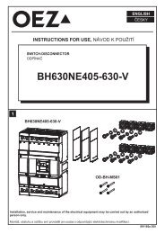
Dimensions<br />
Neutral pole<br />
OPV14-N<br />
Rated operating current I e<br />
63 A<br />
Thermal current with disconnecting<br />
link ZPV14<br />
I th<br />
110 A/25 mm 2<br />
Utilization category of the neutral pole at I e<br />
AC-20B<br />
Rated short-time withstand current I cw<br />
1s 1.6 kA<br />
Rated short-circuit making capacity at<br />
690 V a.c.<br />
I cm<br />
7.5 kA<br />
Rated short-circuit making capacity<br />
at 250 V d.c.<br />
I cm<br />
5.1 kA<br />
Power losses with disconnecting link at I e<br />
P v<br />
4 W<br />
Connection cross-section 0.5 ÷ 25 mm 2<br />
S-3L-27-1000/16<br />
4<br />
26.7<br />
1.5<br />
17<br />
28.5<br />
14.9<br />
S-3L-27-1000/25<br />
.<br />
.<br />
S-3L-27-156/16SN<br />
7.5<br />
27<br />
2<br />
Diagram<br />
18.3<br />
27<br />
42<br />
1 1 1 3 1 3 1 3 5 1 3 5 7 1 3 5 7<br />
2 2 2 4 2 4 2 4 6 2 4 6 8 2 4 6 8<br />
pole pole pole pole pole pole pole<br />
C5
Fuse-links for semiconductor protection<br />
CONDITIONS <strong>FOR</strong> USE OF <strong>FUSE</strong>-LINKS IN <strong>FUSE</strong> <strong>SWITCH</strong>-<strong>DISCONNECTORS</strong><br />
Use of cylindrical fuse-links PV510 in fuse switch-disconnectors OPV10 installed side-by-side<br />
Cross-section of Cu<br />
Reduced rated current [A]<br />
Fuse-link<br />
conductor<br />
[mm 2 ]<br />
1 - pole 3 - pole 7≥ pole<br />
PV510 6A 1 6 6 6<br />
PV510 8A<br />
1.5 8 8 7.5<br />
2.5 8 8 8<br />
PV510 10A 1.5 10 10 10<br />
PV510 12A<br />
1.5 12 12 11<br />
2.5 12 12 12<br />
2.5 16 14 12.5<br />
PV510 16A<br />
4 16 14.5 13<br />
6 16 16 14.5<br />
10 16 16 16<br />
2.5 20 16 15<br />
4 20 17.5 15.5<br />
PV510 20A<br />
6 20 18.5 17<br />
10 20 19.5 18.5<br />
16 20 20 20<br />
4 24 20 18<br />
6 25 21.5 20<br />
PV510 25A<br />
10 25 23.5 22<br />
16 25 25 24<br />
25 25 25 25<br />
6 28 25 23<br />
PV510 32A<br />
10 30 26.5 25.5<br />
16 31.5 28.5 27.5<br />
25 32 29.5 29.5<br />
Use of cylindrical fuse-links PV514 in fuse switch-disconnectors OPV14 installed side-by-side<br />
t v [s]<br />
4<br />
10<br />
5<br />
3<br />
10<br />
5<br />
2<br />
10<br />
5<br />
1<br />
10<br />
5<br />
0<br />
10<br />
5<br />
-1<br />
10<br />
5<br />
-2<br />
10<br />
5<br />
-3<br />
10<br />
5<br />
-4<br />
10<br />
Prearcing time/current characteristic for PV510 installed in OPV10<br />
I [A] n<br />
6 8<br />
10 16<br />
12 20<br />
25 32<br />
10<br />
5 10 5 10 5 10<br />
0 1 2 3<br />
I p [A]<br />
1h<br />
30<br />
20<br />
10<br />
4<br />
2<br />
1min<br />
40<br />
20<br />
10<br />
6<br />
4<br />
2<br />
1s<br />
100<br />
10<br />
1ms<br />
Cross-section of<br />
Max. current load [A]<br />
Fuse-link<br />
Cu conductor<br />
[mm 2 ]<br />
1 - pole 3 - pole 7≥ pole<br />
PV514 6A 1 6 6 6<br />
PV514 8A<br />
1.5 8 7.5 7<br />
2.5 8 8 7.5<br />
PV510 10A<br />
1.5 10 9.5 9<br />
2.5 10 10 9.5<br />
PV514 12A<br />
1.5 12 11.5 10.5<br />
2.5 12 12 11.5<br />
2.5 16 14 13<br />
PV514 16A<br />
4 16 14.5 14<br />
6 16 15 14.5<br />
2.5 19 16 14<br />
PV514 20A<br />
4 20 17 15<br />
6 20 18 17<br />
4 23 20 19<br />
PV514 25A<br />
6 25 21 20<br />
10 25 23 21<br />
16 25 24 22<br />
6 27 23 21<br />
PV514 32A<br />
10 29 24 22<br />
16 31 26 24<br />
25 34 29 28<br />
10 37 31 30<br />
PV514 40A<br />
16 40 33 32<br />
25 40 35 34<br />
10 40 35 33<br />
PV514 50A<br />
16 42 37 36<br />
25 46 40 39<br />
PV514 63A<br />
16 50 15 42<br />
25 55 47 47<br />
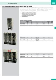
t v [s]<br />
4<br />
10<br />
5<br />
3<br />
10<br />
5<br />
2<br />
10<br />
5<br />
1<br />
10<br />
5<br />
0<br />
10<br />
5<br />
-1<br />
10<br />
5<br />
-2<br />
10<br />
5<br />
-3<br />
10<br />
5<br />
-4<br />
10<br />
Prearcing time/current characteristic for PV514 installed in OPV14<br />
1h<br />
30<br />
20<br />
10<br />
4<br />
2<br />
1min<br />
40<br />
20<br />
10<br />
6<br />
4<br />
2<br />
1s<br />
100<br />
10<br />
1ms<br />
I n [A] 6<br />
8<br />
10<br />
12<br />
16<br />
20<br />
25<br />
32<br />
40<br />
50<br />
63<br />
0<br />
1<br />
2<br />
3<br />
10 5 10 5 10 5 10<br />
I p [A]<br />
I33