

Type AT Signal - Alstom
Type AT Signal - Alstom
Type AT Signal - Alstom

You also want an ePaper? Increase the reach of your titles
YUMPU automatically turns print PDFs into web optimized ePapers that Google loves.
Corrective Maintenance<br />
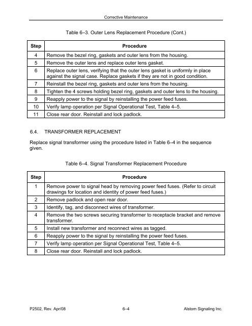
Table 6–3. Outer Lens Replacement Procedure (Cont.)<br />
Step<br />
Procedure<br />
4 Remove the bezel ring, gaskets and outer lens from the housing.<br />
5 Remove the outer lens and replace outer lens gasket.<br />
6 Replace outer lens, verifying that the outer lens gasket is uniformly in place<br />
against the signal case. Replace gaskets if they are not in good condition.<br />
7 Reinstall the bezel ring, gaskets and outer lens from the housing.<br />
8 Tighten the 4 screws holding bezel ring, gaskets and outer lens to the housing.<br />
9 Reapply power to the signal by reinstalling the power feed fuses.<br />
10 Verify lamp operation per <strong>Signal</strong> Operational Test, Table 4–5.<br />
11 Close rear door. Reinstall and lock padlock.<br />
6.4. TRANSFORMER REPLACEMENT<br />
Replace signal transformer using the procedure listed in Table 6–4 in the sequence<br />
given.<br />
Table 6–4. <strong>Signal</strong> Transformer Replacement Procedure<br />
Step<br />
Procedure<br />
1 Remove power to signal head by removing power feed fuses. (Refer to circuit<br />
drawings for location and identity of power feed fuses.)<br />
2 Remove padlock and open rear door.<br />
3 Identify, tag, and disconnect wires of transformer.<br />
4 Remove the two screws securing transformer to receptacle bracket and remove<br />
transformer.<br />
5 Install new transformer and reconnect wires as tagged.<br />
6 Reapply power to the signal by reinstalling the power feed fuses.<br />
7 Verify lamp operation per <strong>Signal</strong> Operational Test, Table 4–5.<br />
8 Close rear door. Reinstall and lock padlock.<br />
P2502, Rev. Apr/08 6–4 <strong>Alstom</strong> <strong>Signal</strong>ing Inc.


