

Type AT Signal - Alstom
Type AT Signal - Alstom
Type AT Signal - Alstom

You also want an ePaper? Increase the reach of your titles
YUMPU automatically turns print PDFs into web optimized ePapers that Google loves.
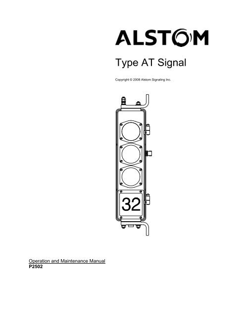
<strong>Type</strong> <strong>AT</strong> <strong>Signal</strong><br />
Copyright © 2008 <strong>Alstom</strong> <strong>Signal</strong>ing Inc.<br />
Operation and Maintenance Manual<br />
P2502
<strong>Type</strong> <strong>AT</strong> <strong>Signal</strong><br />
Copyright © 2008 <strong>Alstom</strong> <strong>Signal</strong>ing Inc.<br />
Operation and Maintenance Manual<br />
<strong>Alstom</strong> <strong>Signal</strong>ing Inc.<br />
P2502, Rev. February 2008, Printed in U.S.A.
LIST OF EFFECTIVE PAGES<br />
P2502, <strong>Type</strong> <strong>AT</strong> <strong>Signal</strong> Operation and Maintenance Manual<br />
ORIGINAL ISSUE D<strong>AT</strong>E: April 2008<br />
CURRENT REVISION AND D<strong>AT</strong>E: April 2008<br />
PAGE<br />
Cover<br />
Title page<br />
Preface<br />
i thru vi<br />
CHANGE OR REVISION LEVEL<br />
Apr/08<br />
Apr/08<br />
Apr/08<br />
Apr/08<br />
1–1 thru 1–8 Apr/08<br />
2–1 thru 2–8 Apr/08<br />
3–1 thru 3–4 Apr/08<br />
4–1 thru 4–8 Apr/08<br />
5–1 thru 5–4 Apr/08<br />
6–1 thru 6–12 Apr/08<br />
7–1 thru 7–42 Apr/08<br />
A–1 thru A–8 Apr/08<br />
P2502, Rev. Apr/08 <strong>Alstom</strong> <strong>Signal</strong>ing Inc.
THIS PAGE INTENTIONALLY LEFT BLANK.<br />
P2502, Rev. Apr/08 <strong>Alstom</strong> <strong>Signal</strong>ing Inc.
PREFACE<br />
NOTICE OF CONFIDENTIAL INFORM<strong>AT</strong>ION<br />
Information contained herein is confidential and is the property of <strong>Alstom</strong><br />
<strong>Signal</strong>ing Incorporated. Where furnished with a proposal, the recipient<br />
shall use it solely to evaluate the proposal. Where furnished to customer, it<br />
shall be used solely for the purposes of inspection, installation or<br />
maintenance. Where furnished to a supplier, it shall be used solely in the<br />
performance of the contract. The information shall not be used or<br />
disclosed by the recipient for any other purposes whatsoever.<br />
FOR QUESTIONS AND INQUIRIES, CONTACT CUSTOMER SERVICE <strong>AT</strong><br />
1–800–717–4477<br />
OR<br />
WWW.ALSTOMSIGNALINGSOLUTIONS.COM<br />
ALSTOM SIGNALING INC.<br />
1025 JOHN STREET<br />
WEST HENRIETTA, NY 14586<br />
REVISION LOG<br />
Revision Date Description By Checked Approved<br />
0 April 2008 Original issue MAS RR NI<br />
P2502, Rev. Apr/08 <strong>Alstom</strong> <strong>Signal</strong>ing Inc.
THIS PAGE INTENTIONALLY LEFT BLANK.<br />
P2502, Rev. Apr/08 <strong>Alstom</strong> <strong>Signal</strong>ing Inc.
ABOUT THE MANUAL<br />
This manual is intended to provide the necessary information to maintain and ensure<br />
proper operation of the <strong>Type</strong> <strong>AT</strong> <strong>Signal</strong>.<br />
The information in this manual is arranged into sections. The title and a brief description<br />
of each section follow:<br />
Section 1 – GENERAL DESCRIPTION: This section gives general information on the<br />
components of the <strong>Type</strong> <strong>AT</strong> <strong>Signal</strong>.<br />
Section 2 – THEORY OF OPER<strong>AT</strong>ION: This section gives general information on the<br />
operation of the <strong>Type</strong> <strong>AT</strong> <strong>Signal</strong>.<br />
Section 3 – INSTALL<strong>AT</strong>ION: This section describes the field installation and setup of<br />
the <strong>Type</strong> <strong>AT</strong> <strong>Signal</strong>.<br />
Section 4 – PREVENTIVE MAINTENANCE: This section describes the tools,<br />
preventive maintenance procedures, and functional tests used on the <strong>Type</strong> <strong>AT</strong> <strong>Signal</strong>.<br />
The frequency and interval, for the performance of the given information, are also<br />
included. Safety precautions are also provided in this section.<br />
Section 5 – TROUBLESHOOTING: This section describes possible failures/symptoms<br />
along with the corrective action for the <strong>Type</strong> <strong>AT</strong> <strong>Signal</strong>.<br />
Section 6 – CORRECTIVE MAINTENANCE: This section describes the adjustment<br />
and replacement procedures associated with corrective maintenance of the <strong>Type</strong> <strong>AT</strong><br />
<strong>Signal</strong>. Safety precautions are also provided in this section.<br />
Section 7 – PARTS C<strong>AT</strong>ALOG: This section identifies and lists the spare parts<br />
associated with operations of the <strong>Type</strong> <strong>AT</strong> <strong>Signal</strong>.<br />
Appendix A – DRAWINGS: This section has representative circuit drawings along with<br />
an installation and space requirement drawing of the <strong>Type</strong> <strong>AT</strong> <strong>Signal</strong>.<br />
P2502, Rev. Apr/08 <strong>Alstom</strong> <strong>Signal</strong>ing Inc.
THIS PAGE INTENTIONALLY LEFT BLANK.<br />
P2502, Rev. Apr/08 <strong>Alstom</strong> <strong>Signal</strong>ing Inc.
MANUAL SPECIAL NOT<strong>AT</strong>IONS<br />
In the <strong>Alstom</strong> manuals, there are three methods used to convey special informational<br />
notations to the reader. These notations are warnings, cautions, and notes. Both<br />
warnings and cautions are readily noticeable by boldface type two lines beneath the<br />
caption.<br />
Warning<br />
A warning is the most important notation to heed. A warning is used to tell the reader<br />
that special attention needs to be paid to the message because if the instructions or<br />
advice is not followed when working on the equipment then the result could be either<br />
serious harm or death. The sudden, unexpected operation of a switch machine, for<br />
example, or the technician contacting the third rail could lead to personal injury or death.<br />
An example of a typical warning notice follows:<br />
Caution<br />
WARNING<br />
WHENEVER THE GEAR COVER IS REMOVED DISCONNECT THE<br />
MOTOR ENERGY. OTHERWISE, THE SWITCH MACHINE MAY<br />
OPER<strong>AT</strong>E UNEXPECTEDLY AND POSSIBLY CAUSE PERSONAL<br />
INJURY.<br />
A caution statement is used when an operating or maintenance procedure, practice,<br />
condition, or statement, which if not strictly adhered to, could result in damage to or<br />
destruction of equipment. A caution statement is also used when personnel could be<br />
surprised if shocked by a circuit operating at a low current. A typical caution found in a<br />
manual is as follows:<br />
Note<br />
CAUTION<br />
Turn power off before attempting to remove or insert circuit boards into a<br />
module. Boards can be damaged if power is not turned off.<br />
A note is normally used to provide minor additional information to the reader to explain<br />
the reason for a given step in a test procedure or to just provide a background detail. An<br />
example of the use of a note follows:<br />
NOTE<br />
A capacitor may be mounted on the circuit board with a RTV adhesive.<br />
Use the same color RTV.<br />
P2502, Rev. Apr/08 <strong>Alstom</strong> <strong>Signal</strong>ing Inc.
THIS PAGE INTENTIONALLY LEFT BLANK.<br />
P2502, Rev. Apr/08 <strong>Alstom</strong> <strong>Signal</strong>ing Inc.
Topic<br />
TABLE OF CONTENTS<br />
Page<br />
1. SECTION 1 – INTRODUCTION............................................................................. 1–1<br />
1.1. SCOPE OF MANUAL ....................................................................................... 1–1<br />
1.2. GENERAL ........................................................................................................ 1–1<br />
1.3. PHYSICAL CHARACTERISTICS ..................................................................... 1–3<br />
1.3.1. Housing.......................................................................................................... 1–4<br />
1.3.2. Lens Assembly .............................................................................................. 1–5<br />
1.4. INCANDESCENT LIGHT SOURCE ................................................................. 1–6<br />
1.5. LED LIGHT SOURCE....................................................................................... 1–7<br />
2. SECTION 2– THEORY OF OPER<strong>AT</strong>ION.............................................................. 2–1<br />
2.1. GENERAL ........................................................................................................ 2–1<br />
2.2. FUNCTIONAL DESCRIPTION ......................................................................... 2–1<br />
2.3. TYPE <strong>AT</strong> INCANDESCENT SIGNAL FUNCTIONAL DESCRIPTION .............. 2–2<br />
2.3.1. <strong>Type</strong> <strong>AT</strong> Incandescent <strong>Signal</strong> Wiring............................................................. 2–3<br />
2.4. LED UNIT FUNCTIONAL DESCRIPTION........................................................ 2–4<br />
2.4.1. LED Lamp Wiring........................................................................................... 2–5<br />
3. SECTION 3 – INSTALL<strong>AT</strong>ION.............................................................................. 3–1<br />
3.1. GENERAL ........................................................................................................ 3–1<br />
3.2. SIGNAL MOUNTING........................................................................................ 3–1<br />
4. SECTION 4 – PREVENTIVE MAINTENANCE...................................................... 4–1<br />
4.1. GENERAL ........................................................................................................ 4–1<br />
4.2. PREVENTIVE MAINTENANCE........................................................................ 4–2<br />
4.2.1. Inspection ...................................................................................................... 4–3<br />
4.2.2. Lens Cleaning................................................................................................ 4–4<br />
4.2.3. Lubrication ..................................................................................................... 4–6<br />
4.2.4. <strong>Signal</strong> Operational Test ................................................................................. 4–7<br />
5. SECTION 5 – TROUBLESHOOTING.................................................................... 5–1<br />
5.1. GENERAL ........................................................................................................ 5–1<br />
5.2. TROUBLESHOOTING GUIDE ......................................................................... 5–1<br />
6. SECTION 6 – CORRECTIVE MAINTENANCE ..................................................... 6–1<br />
6.1. GENERAL ........................................................................................................ 6–1<br />
6.2. INCANDESCENT LAMP REPLACEMENT....................................................... 6–2<br />
6.3. LENS REPLACEMENT .................................................................................... 6–3<br />
6.4. TRANSFORMER REPLACEMENT .................................................................. 6–4<br />
6.5. LAMP RECEPTACLE REPLACEMENT ........................................................... 6–5<br />
6.6. LED MODULE REPLACEMENT ...................................................................... 6–6<br />
6.7. LED BOARD/ILLUMIN<strong>AT</strong>ED NUMBER PL<strong>AT</strong>E REPLACEMENT.................... 6–8<br />
6.8. SIGNAL HEAD REPLACEMENT...................................................................... 6–9<br />
6.9. WAYSIDE SIGNAL SITING............................................................................ 6–11<br />
P2502, Rev. Apr/08 i <strong>Alstom</strong> <strong>Signal</strong>ing Inc.
Topic<br />
TABLE OF CONTENTS (CONT.)<br />
Page<br />
7. SECTION 7 – PARTS C<strong>AT</strong>ALOG ......................................................................... 7–1<br />
7.1. GENERAL ........................................................................................................ 7–1<br />
7.2. EXAMPLE SIGNALS ........................................................................................ 7–1<br />
7.3. LENSES ........................................................................................................... 7–3<br />
7.4. SINGLE ASPECT TYPE <strong>AT</strong> INCANDESCENT SIGNAL UNIT WITH<br />
TRANSFORMER.............................................................................................. 7–5<br />
7.5. 3 ASPECT TYPE <strong>AT</strong> INCANDESCENT SIGNAL, CEILING/HORIZONTAL<br />
MOUNT ............................................................................................................ 7–9<br />
7.6. 3 ASPECT TYPE <strong>AT</strong> INCANDESCENT SIGNAL, WALL MOUNT ................. 7–13<br />
7.7. 3 ASPECT TYPE <strong>AT</strong> INCANDESCENT SIGNAL, POLE MOUNT ................. 7–17<br />
7.8. LED UNITS..................................................................................................... 7–21<br />
7.9. 2 ASPECT TYPE <strong>AT</strong> SIGNAL UNIT WITH LED LIGHT SOURCE,<br />
POLE MOUNT................................................................................................ 7–23<br />
7.10. 7 ASPECT TYPE <strong>AT</strong> SIGNAL UNIT WITH LED LIGHT SOURCE,<br />
POLE MOUNT................................................................................................ 7–31<br />
7.11. 3 ASPECT TYPE <strong>AT</strong> SIGNAL UNIT WITH LED LIGHT SOURCE,<br />
CEILING/HORIZONTAL MOUNT ................................................................... 7–39<br />
A. APPENDIX A – DRAWINGS .................................................................................A–1<br />
A.1. GENERAL ........................................................................................................A–1<br />
A.2. TYPE <strong>AT</strong> INCANDESCENT SIGNAL WIRING DIAGRAMS.............................A–1<br />
A.3. TYPE <strong>AT</strong> SIGNAL UNIT WITH LED P/N 20179-0XX-00 WIRING DIAGRAMS A–4<br />
P2502, Rev. Apr/08 ii <strong>Alstom</strong> <strong>Signal</strong>ing Inc.
Description<br />
LIST OF FIGURES<br />
Page<br />
Figure 1–1. Typical Three Aspect <strong>Type</strong> <strong>AT</strong> <strong>Signal</strong> ..................................................... 1–2<br />
Figure 1–2. Typical Three Aspect and Single Aspect <strong>Type</strong> <strong>AT</strong> <strong>Signal</strong> Housings,<br />
Side View .............................................................................................................. 1–4<br />
Figure 1–3. Typical <strong>Type</strong> <strong>AT</strong> <strong>Signal</strong> Active Light Compartment ................................. 1–5<br />
Figure 1–4. Typical <strong>Type</strong> <strong>AT</strong> Incandescent <strong>Signal</strong> ..................................................... 1–6<br />
Figure 1–5. Typical <strong>Type</strong> <strong>AT</strong> <strong>Signal</strong> LED Light Source Unit ....................................... 1–7<br />
Figure 2–1. Typical <strong>Type</strong> <strong>AT</strong> Incandescent <strong>Signal</strong> With Transformers<br />
Circuit Diagram...................................................................................................... 2–2<br />
Figure 2–2. Typical 3 Aspect <strong>Type</strong> <strong>AT</strong> Incandescent <strong>Signal</strong> With Transformers and<br />
Illuminated Number Plate Wiring........................................................................... 2–3<br />
Figure 2–3. Typical <strong>Type</strong> <strong>AT</strong> 3 Aspect LED <strong>Signal</strong> Wiring Diagram........................... 2–5<br />
Figure 2–4. Typical <strong>Type</strong> <strong>AT</strong> 3 Aspect LED <strong>Signal</strong> Wiring Diagram (Center Aspect<br />
is Blank) ................................................................................................................ 2–6<br />
Figure 2–5. Typical <strong>Type</strong> <strong>AT</strong> LED Single Aspect <strong>Signal</strong> Wiring Diagram................... 2–7<br />
Figure 3–1. Typical Wall Mount <strong>Type</strong> <strong>AT</strong> <strong>Signal</strong> ........................................................ 3–2<br />
Figure 3–2. Typical Ceiling (Horizontal) Mount <strong>Type</strong> <strong>AT</strong> <strong>Signal</strong> ................................. 3–3<br />
Figure 3–3. Typical 3 Aspect Pole Mount <strong>Type</strong> <strong>AT</strong> <strong>Signal</strong> ......................................... 3–4<br />
Figure 5–1. Incandescent <strong>Signal</strong> Aspect Dim or Not Illuminated................................ 5–2<br />
Figure 5–2. LED <strong>Signal</strong> Aspect Dim or Not Illuminated.............................................. 5–3<br />
Figure 5–3. LED or Illuminated Number Dim or Not Illuminated................................. 5–4<br />
Figure 7–1. Replacement Outer Lenses and Gaskets................................................ 7–3<br />
Figure 7–2. Example Single Aspect <strong>Type</strong> <strong>AT</strong> Incandescent <strong>Signal</strong> Unit With<br />
Transformer, <strong>AT</strong>007-000-00.................................................................................. 7–5<br />
Figure 7–3. Example 3 Aspect <strong>Type</strong> <strong>AT</strong> Incandescent <strong>Signal</strong> Unit Without<br />
Transformers, With Illuminated LED Number Plate, Ceiling/Horizontal Mount,<br />
<strong>AT</strong>000-108-00 ....................................................................................................... 7–9<br />
Figure 7–4. Example 3 Aspect <strong>Type</strong> <strong>AT</strong> Incandescent <strong>Signal</strong> Unit With<br />
Transformers, Enameled Number Plate, Door Stop and Side Plate, Wall Mount,<br />
<strong>AT</strong>000-001-00 ..................................................................................................... 7–13<br />
Figure 7–5. Example 3 Aspect <strong>Type</strong> <strong>AT</strong> Incandescent <strong>Signal</strong> Unit With<br />
Transformers, Enameled Number Plate, Door Stop and Side Plate, Pole Mount,<br />
<strong>AT</strong>000-024-00 ..................................................................................................... 7–17<br />
Figure 7–6. LED Unit P/N 20179-0XX-00................................................................. 7–21<br />
Figure 7–7. Example 2 Aspect <strong>Type</strong> <strong>AT</strong> <strong>Signal</strong> Unit With LED Light Source,<br />
Pole Mount, <strong>AT</strong>100-001-00 ................................................................................. 7–23<br />
Figure 7–8. Example 7 Aspect <strong>Type</strong> <strong>AT</strong> <strong>Signal</strong> Unit With LED Light Source, Pole<br />
Mount, <strong>AT</strong>100-002-00 ......................................................................................... 7–31<br />
Figure 7–9. Example 3 Aspect <strong>Type</strong> <strong>AT</strong> <strong>Signal</strong> Unit With LED Light Source,<br />
Ceiling/Horizontal Mount ..................................................................................... 7–39<br />
P2502, Rev. Apr/08 iii <strong>Alstom</strong> <strong>Signal</strong>ing Inc.
Description<br />
LIST OF FIGURES (CONT.)<br />
Page<br />
Figure A–1. Typical Single Aspect <strong>Type</strong> <strong>AT</strong> Incandescent <strong>Signal</strong> Wiring Diagram ....A–1<br />
Figure A–2. Typical 3 Aspect <strong>Type</strong> <strong>AT</strong> Incandescent <strong>Signal</strong> Unit With Illuminated<br />
Number plate and Transformers Wiring Diagram..................................................A–2<br />
Figure A–3. Typical 4 Aspect <strong>Type</strong> <strong>AT</strong> Incandescent <strong>Signal</strong> Unit With Enameled<br />
Number Plate and Transformers Wiring Diagram (Single Aspect Plus 3 Aspect) .A–3<br />
Figure A–4. Typical Single Aspect <strong>Type</strong> <strong>AT</strong> <strong>Signal</strong> With LED Unit P/N 20179-0XX-00<br />
Wiring Diagram......................................................................................................A–4<br />
Figure A–5. Typical 3 Aspect <strong>Type</strong> <strong>AT</strong> <strong>Signal</strong> With LED Unit P/N 20179-0XX-00 Wiring<br />
Diagram.................................................................................................................A–5<br />
Figure A–6. Typical 3 Aspect <strong>Type</strong> <strong>AT</strong> <strong>Signal</strong> With LED Unit P/N 20179-0XX-00 and<br />
Illuminated Number Wiring Diagram......................................................................A–6<br />
Figure A–7. Typical Four Aspect <strong>Type</strong> <strong>AT</strong> <strong>Signal</strong> With LED Unit P/N 20179-0XX-00<br />
Wiring Diagram (Single Aspect Plus and 3 Aspect)...............................................A–7<br />
P2502, Rev. Apr/08 iv <strong>Alstom</strong> <strong>Signal</strong>ing Inc.
Description<br />
LIST OF TABLES<br />
Page<br />
Table 1–1. <strong>Type</strong> <strong>AT</strong> <strong>Signal</strong> Basic Housing Dimensions .............................................. 1–5<br />
Table 4–1. Preventive Maintenance Index ................................................................. 4–2<br />
Table 4–2. Inspection Procedures.............................................................................. 4–3<br />
Table 4–3. External Lens Cleaning Procedure........................................................... 4–5<br />
Table 4–4. Lubrication Procedure .............................................................................. 4–6<br />
Table 4–5. <strong>Signal</strong> Operational Test Procedure .......................................................... 4–7<br />
Table 5–1. Troubleshooting Symbols......................................................................... 5–1<br />
Table 6–1. Corrective Maintenance Procedures ........................................................ 6–1<br />
Table 6–2. Incandescent Aspect Lamp Replacement Procedure............................... 6–2<br />
Table 6–3. Outer Lens Replacement Procedure ........................................................ 6–3<br />
Table 6–4. <strong>Signal</strong> Transformer Replacement Procedure ........................................... 6–4<br />
Table 6–5. Receptacle Replacement Procedure........................................................ 6–5<br />
Table 6–6. LED P/N 20179-0XX-XX Module Replacement Procedure ...................... 6–6<br />
Table 6–7. LED Board/Illuminated Number Plate Replacement Procedure ............... 6–8<br />
Table 6–8. <strong>Signal</strong> Head Replacement Procedure ...................................................... 6–9<br />
Table 6–9. Wayside <strong>Signal</strong> Siting Procedure ........................................................... 6–11<br />
Table 7–1. Replacement Outer Lenses...................................................................... 7–3<br />
Table 7–2. Example Single Aspect <strong>Type</strong> <strong>AT</strong> Incandescent <strong>Signal</strong> Unit With<br />
Transformer, <strong>AT</strong>007-000-02 Part Numbers........................................................... 7–7<br />
Table 7–3. Example 3 Aspect <strong>Type</strong> <strong>AT</strong> Incandescent <strong>Signal</strong> Unit Without<br />
Transformers, With Illuminated LED Number Plate, Ceiling/Horizontal Mount,<br />
<strong>AT</strong>000-108-01 Part Numbers .............................................................................. 7–11<br />
Table 7–4. Example 3 Aspect <strong>Type</strong> <strong>AT</strong> Incandescent <strong>Signal</strong> Unit With<br />
Transformers, Enameled Number Plate, Door Stop and Side Plate, Wall Mount,<br />
<strong>AT</strong>000-001-01 Part Numbers .............................................................................. 7–15<br />
Table 7–5. Example 3 Aspect <strong>Type</strong> <strong>AT</strong> Incandescent <strong>Signal</strong> Unit With<br />
Transformers, Enameled Number Plate, Door Stop and Side Plate, Pole Mount,<br />
<strong>AT</strong>000-024-01 Part Numbers .............................................................................. 7–19<br />
Table 7–6. LED Unit Part Numbers.......................................................................... 7–21<br />
Table 7–7. Example 2 Aspect <strong>Type</strong> <strong>AT</strong> <strong>Signal</strong> Unit With LED Light Source, Pole<br />
Mount, <strong>AT</strong>100-001-01 Part Numbers .................................................................. 7–27<br />
Table 7–8. Example 7 Aspect <strong>Type</strong> <strong>AT</strong> <strong>Signal</strong> Unit With LED Light Source, Pole<br />
Mount, <strong>AT</strong>100-002-01 Part Numbers .................................................................. 7–35<br />
Table 7–9. Example 3 Aspect <strong>Type</strong> <strong>AT</strong> <strong>Signal</strong> Unit With LED Light Source,<br />
Ceiling/Horizontal Mount Part Numbers .............................................................. 7–41<br />
P2502, Rev. Apr/08 v <strong>Alstom</strong> <strong>Signal</strong>ing Inc.
THIS PAGE INTENTIONALLY LEFT BLANK.<br />
P2502, Rev. Apr/08 vi <strong>Alstom</strong> <strong>Signal</strong>ing Inc.
Introduction<br />
1. SECTION 1 – INTRODUCTION<br />
1.1. SCOPE OF MANUAL<br />
This manual is intended to provide the necessary information to maintain and ensure<br />
proper operation of the <strong>Type</strong> <strong>AT</strong> <strong>Signal</strong>. The technical material in this manual assumes<br />
the reader has a basic knowledge of railroad signaling terminology and basic<br />
maintenance principles.<br />
1.2. GENERAL<br />
This section briefly describes the components and physical characteristics of a typical<br />
<strong>Alstom</strong> <strong>Type</strong> <strong>AT</strong> transit signal, available with two types of light fixtures:<br />
• Incandescent Lamp P/N 48088-028-00<br />
• LED Unit P/N 20179-0XX-00<br />
The components and configuration of signals can vary depending on the specific<br />
requirements of their locations. <strong>Signal</strong>s can be stacked to produce a multi Aspect signal.<br />
The signal can be wall, ceiling or pole mounted through the use of mounting brackets<br />
attached to the signal housing. Wall brackets hold a signal securely to a concrete wall or<br />
ceiling through the use of concrete bolts. A wall signal can be mounted in either a left or<br />
right hand configuration. These mounting configurations are produced by changing the<br />
position of the wall mounting bracket attached to the signal housing. Ladders can be<br />
provided where required. The <strong>Type</strong> <strong>AT</strong> <strong>Signal</strong> conforms to requirements of the AREMA<br />
<strong>Signal</strong> Manual, Part 7.1.1.<br />
P2502, Rev. Apr/08 1–1 <strong>Alstom</strong> <strong>Signal</strong>ing Inc.
Introduction<br />
LENS<br />
ASSEMBLIES (3)<br />
HINGED<br />
BACK DOOR<br />
NUMBER PL<strong>AT</strong>E ENAMEL<br />
OR ILLUMIN<strong>AT</strong>ED<br />
3 ASPECT<br />
SIGNAL HOUSING<br />
Figure 1–1. Typical Three Aspect <strong>Type</strong> <strong>AT</strong> <strong>Signal</strong><br />
P2502, Rev. Apr/08 1–2 <strong>Alstom</strong> <strong>Signal</strong>ing Inc.
Introduction<br />
1.3. PHYSICAL CHARACTERISTICS<br />
The <strong>Type</strong> <strong>AT</strong> <strong>Signal</strong> arrangement as well as the aspects and enamel number plate, vary<br />
depending on the location requirements. The configuration of the signal and use of<br />
illuminated or enamel number plate depends on the requirements of the location. <strong>Signal</strong><br />
configurations are identified by the signal drawing number. Example configurations are<br />
shown and described within this manual.<br />
The <strong>Type</strong> <strong>AT</strong> 3 Aspect <strong>Signal</strong>, as shown in Figure 1–1, consists of a housing with<br />
hinged door, an illuminated or enamel number plate, three Aspect lens assemblies, and<br />
internal electrical components to illuminate the aspects and number plate if so<br />
configured.<br />
The <strong>Type</strong> <strong>AT</strong> Single Aspect <strong>Signal</strong> is often used in a multi Aspect application. The<br />
single aspect signal consists of a housing unit with a hinged door, a single aspect lens<br />
assembly, and internal electrical components to illuminate the aspect.<br />
This signal is available with the following options:<br />
• Mounting:<br />
− Wall Right Hand<br />
− Wall Left Hand<br />
− Column<br />
− Pole<br />
− Horizontal<br />
• Aspect Arrangements:<br />
− Red<br />
− Yellow<br />
− Lunar White<br />
− Timing indication (S)<br />
− Speed indication (15 or 20)<br />
− Blank (metal disk covers lamp compartment)<br />
P2502, Rev. Apr/08 1–3 <strong>Alstom</strong> <strong>Signal</strong>ing Inc.
Introduction<br />
1.3.1. Housing<br />
The signal housing is of cast-aluminum construction. Access to the internal parts of the<br />
signal is made through a hinged door at the rear of the housing.<br />
The <strong>Type</strong> <strong>AT</strong> 3 Aspect <strong>Signal</strong> is internally divided into four potentially active light<br />
compartments. Three compartments are used for aspect signals and one for the<br />
number display (number plate, illuminated (incandescent) number or LED number). The<br />
door of the three Aspect signal is equipped with two ventilators to prevent moisture and<br />
heat build-up within the housing and a gasket with sealant to prevent water from<br />
entering the housing.<br />
The <strong>Type</strong> <strong>AT</strong> Single Aspect <strong>Signal</strong> is available with or without an enamel number plate.<br />
The single aspect door has one ventilator. A latch is provided to padlock the door and<br />
prevent unauthorized access.<br />
Housings can be stacked to make 4, 5, 6, 7, or 8 aspect configurations.<br />
VENTIL<strong>AT</strong>ORS<br />
4 COMPARTMENTS IN<br />
A 3 ASPECT SIGNAL<br />
NUMBER PL<strong>AT</strong>E<br />
Figure 1-2. Typical Three Aspect and Single Aspect <strong>Type</strong> <strong>AT</strong> <strong>Signal</strong> Housings,<br />
Side View<br />
P2502, Rev. Apr/08 1–4 <strong>Alstom</strong> <strong>Signal</strong>ing Inc.
`<br />
Introduction<br />
Table 1–1. <strong>Type</strong> <strong>AT</strong> <strong>Signal</strong> Basic Housing Dimensions<br />
Dimension 3 Aspect Single Aspect<br />
Height 28.75" (73 cm) 9.75" (24.8 cm)<br />
Width 8.60" (21.8 cm) 8.60" (21.08 cm)<br />
Depth 9.69" (24.6 cm) 9.69" (24.6 cm)<br />
Outer Lens Diameter 5.0" (12.7 cm) 5.0" (12.7 cm)<br />
1.3.2. Lens Assembly<br />
The lens assembly of a <strong>Type</strong> <strong>AT</strong> <strong>Signal</strong> aspect, whether incandescent or LED, consists<br />
of a colored (Green, Yellow, or Red) lens and a mounting ring that holds the lens to the<br />
signal case. See Figure 1–3 for lens detail.<br />
LENS<br />
GASKETS<br />
LAMPS AND LAMP<br />
RECEPTACLES (2)<br />
LENS<br />
GASKETS<br />
LED LAMP UNIT<br />
TERMINAL POSTS<br />
BEZEL<br />
RING<br />
BEZEL<br />
RING<br />
LED UNIT<br />
OUTER<br />
LENS<br />
SCREW &<br />
WASHER<br />
GASKET<br />
LIGHTING<br />
TRANSFORMERS<br />
TERMINALS<br />
OUTER<br />
LENS<br />
SCREW &<br />
WASHER<br />
TYPE <strong>AT</strong> SINGLE ASPECT INCANDESCENT SIGNAL<br />
GASKET<br />
CENTERLINE OF<br />
OUTER LENS &<br />
LAMP UNIT LENS<br />
LED LAMP UNIT<br />
MOUNTING SCREW<br />
& WASHER<br />
TYPE <strong>AT</strong> SINGLE ASPECT LED SIGNAL<br />
Figure 1–3. Typical <strong>Type</strong> <strong>AT</strong> <strong>Signal</strong> Active Light Compartment<br />
P2502, Rev. Apr/08 1–5 <strong>Alstom</strong> <strong>Signal</strong>ing Inc.
Introduction<br />
1.4. INCANDESCENT LIGHT SOURCE<br />
Each active incandescent light source compartment uses two lamps. Each lamp has a<br />
single filament.<br />
An active aspect or illuminated number plate light compartment contains a lighting<br />
transformer, terminals for power connection, and appropriate lamp receptacles as<br />
shown in Figure 1–4.<br />
LIGHTING<br />
TRANSFORMERS (2)<br />
ASPECT<br />
LENS<br />
ASSEMBLY<br />
LAMPS AND<br />
LAMP RECEPTACLES (2)<br />
TERMINALS<br />
LAMPS AND LAMP<br />
RECEPTACLES (2)<br />
TERMINALS<br />
FRONT VIEW<br />
ILLUMIN<strong>AT</strong>ED<br />
NUMBER PL<strong>AT</strong>E<br />
SIDE VIEW<br />
LIGHTING<br />
TRANSFORMERS (2)<br />
Figure 1-4. Typical <strong>Type</strong> <strong>AT</strong> Incandescent <strong>Signal</strong><br />
P2502, Rev. Apr/08 1–6 <strong>Alstom</strong> <strong>Signal</strong>ing Inc.
Introduction<br />
1.5. LED LIGHT SOURCE<br />
The LED light source unit P/N 20179-0XX-00 measures 2.2” (5.6 cm) in diameter. It is a<br />
self contained unit; the lens and individual LEDs are not replaceable.<br />
Two secured color coded 300V, 125ºC, 16 AWG jacketed wires 12" (30.5 cm) long with<br />
ring terminals compatible with the AAR terminal posts (.242” O.D. [.61 cm]) are<br />
provided. The AAR terminal posts are provided for field electrical connections.<br />
Figure 1-5. Typical <strong>Type</strong> <strong>AT</strong> <strong>Signal</strong> LED Light Source Unit<br />
The LED lamp units used on this project have the following physical characteristics:<br />
• Color • Light Angle<br />
− Red<br />
− 20 degree<br />
− Green • Operating Voltage<br />
− Yellow<br />
− 110 VAC (60Hz)<br />
− Lunar White • Brightness<br />
• BackLight − Fixed, Not Adjustable<br />
P2502, Rev. Apr/08 1–7 <strong>Alstom</strong> <strong>Signal</strong>ing Inc.
Introduction<br />
.<br />
THIS PAGE INTENTIONALLY LEFT BLANK.<br />
P2502, Rev. Apr/08 1–8 <strong>Alstom</strong> <strong>Signal</strong>ing Inc.
Theory of Operation<br />
2. SECTION 2– THEORY OF OPER<strong>AT</strong>ION<br />
2.1. GENERAL<br />
This section contains operating information on the <strong>Alstom</strong> <strong>Type</strong> <strong>AT</strong> <strong>Signal</strong> along with<br />
diagrams showing power distribution and wiring to the signal.<br />
2.2. FUNCTIONAL DESCRIPTION<br />
<strong>Type</strong> <strong>AT</strong> <strong>Signal</strong>s are controlled externally through relay logic circuits or vital processors.<br />
Depending on the distance of the signal from the relay room, power supplied to the<br />
signal may vary.<br />
P2502, Rev. Apr/08 2–1 <strong>Alstom</strong> <strong>Signal</strong>ing Inc.
Theory of Operation<br />
2.3. TYPE <strong>AT</strong> INCANDESCENT SIGNAL FUNCTIONAL DESCRIPTION<br />
<strong>Type</strong> <strong>AT</strong> Incandescent <strong>Signal</strong>s are configured with transformers to operate on fused 60<br />
Hz (ungrounded), 110 VAC power, controlled externally through relay logic circuits.<br />
Depending on the distance of the signal from the power source, the nominal 110 VAC<br />
power supplied to the primary windings of the signal transformers may vary. It must,<br />
however, be between 90 to 130 VAC (60 Hz) for the signal to function properly.<br />
Figure 2–1 is a simplified circuit diagram of a <strong>Type</strong> <strong>AT</strong> 3 Aspect <strong>Signal</strong> with<br />
transformers. One aspect contains two single filament lamps installed in a receptacle<br />
assembly consisting of two non-tapping transformers, two lamp receptacles, and a<br />
terminal block attached to a mounting bracket.<br />
Terminal connection points A, C, and E from terminal blocks within the three signal<br />
aspects, are connected to the signal lighting relay logic circuits. These circuits receive<br />
power through a fused feed, from an energy source in the relay room. The three<br />
aspects, points A, C, and E, are fed from a single fuse. The common 1 and 2 feeds<br />
(points B and F) are not fused. These feeds are connected to the same energy source<br />
but not through the relay logic control circuits. A signal lamp receives the 10 VAC from a<br />
transformer within the signal. Detailed wiring diagrams on specific <strong>Type</strong> <strong>AT</strong> <strong>Signal</strong>s are<br />
given in Appendix A.<br />
LAMP<br />
TERMINAL CONNECTION POINTS<br />
TRANSFORMER A TRANSFORMER<br />
LAMP<br />
10<br />
VAC<br />
110<br />
VAC<br />
110<br />
VAC<br />
10<br />
VAC<br />
ASPECT 1<br />
B<br />
C<br />
10<br />
VAC<br />
110<br />
VAC<br />
110<br />
VAC<br />
10<br />
VAC<br />
ASPECT 2<br />
D<br />
E<br />
10<br />
VAC<br />
110<br />
VAC<br />
110<br />
VAC<br />
10<br />
VAC<br />
ASPECT 3<br />
F<br />
Figure 2–1. Typical <strong>Type</strong> <strong>AT</strong> Incandescent <strong>Signal</strong> With Transformers Circuit Diagram<br />
P2502, Rev. Apr/08 2–2 <strong>Alstom</strong> <strong>Signal</strong>ing Inc.
Theory of Operation<br />
2.3.1. <strong>Type</strong> <strong>AT</strong> Incandescent <strong>Signal</strong> Wiring<br />
Figure 2–2 is a wiring diagram of a typical <strong>Type</strong> <strong>AT</strong> Incandescent 3 Aspect <strong>Signal</strong> with<br />
transformers. The signal wiring shown in dotted lines represents the field wiring of a<br />
seven conductor, number 14 AWG cable. The internal wiring of lamps and transformers<br />
are represented by solid lines.<br />
G<br />
Y<br />
R<br />
ILLUMIN<strong>AT</strong>ED<br />
NO. PL<strong>AT</strong>E<br />
110 VAC<br />
COMMON (BCX OR ACX)<br />
LAMPS<br />
TRANSFORMERS<br />
TERMINAL<br />
BLOCK<br />
BLACK<br />
BCX<br />
ILLUM<br />
NO. PL<strong>AT</strong>E<br />
R Y ACX G<br />
RED<br />
TYPICAL WIRING OF A<br />
LAMP AND TRANSFORMER<br />
Figure 2–2. Typical 3 Aspect <strong>Type</strong> <strong>AT</strong> Incandescent <strong>Signal</strong> With Transformers and<br />
Illuminated Number Plate Wiring<br />
P2502, Rev. Apr/08 2–3 <strong>Alstom</strong> <strong>Signal</strong>ing Inc.
Theory of Operation<br />
2.4. LED UNIT FUNCTIONAL DESCRIPTION<br />
The LED Unit P/N 20179-0XX-00 is available in 4 colors:<br />
• Green LED 20179-008-00<br />
• Red LED 20179-009-00<br />
• Yellow LED 20179-010-00<br />
• Lunar White LED 20179-011-00<br />
This is a single, self-contained device that does not require any field assembly. The<br />
lamp is wired via ring terminals to AAR terminal posts within the signal unit.<br />
Each unit contains an LED board and a power supply board contained in the signal<br />
housing. These housings are replaceable as a unit and are not serviceable.<br />
The LED unit power boards operate from 90 to 130 VAC (60 Hz.<br />
P2502, Rev. Apr/08 2–4 <strong>Alstom</strong> <strong>Signal</strong>ing Inc.
Theory of Operation<br />
2.4.1. LED Lamp Wiring<br />
Figure 2–3 is a wiring diagram of a typical three aspect LED Unit P/N 20179-0XX-00<br />
LED signal configured, green, yellow, and red.<br />
The signal wiring shown in dotted lines represents field wiring of multi-conductor<br />
number 14 AWG cable. <strong>Signal</strong> number is represented by xxx in this example. See<br />
Appendix A for additional example wiring diagrams.<br />
G<br />
1<br />
2<br />
Y<br />
1<br />
2<br />
R<br />
1<br />
2<br />
xxxRG<br />
xxxHG<br />
ACX<br />
xxxDG<br />
Figure 2-3. Typical <strong>Type</strong> <strong>AT</strong> 3 Aspect LED <strong>Signal</strong> Wiring Diagram<br />
P2502, Rev. Apr/08 2–5 <strong>Alstom</strong> <strong>Signal</strong>ing Inc.
Theory of Operation<br />
Figure 2–4 is a wiring diagram of a typical three aspect LED signal (one aspect blank)<br />
configured red, blank, red.<br />
The signal wiring shown in dotted lines represent field wiring of four-conductor number<br />
14 AWG cable.<br />
R<br />
1<br />
2<br />
X<br />
R<br />
1<br />
2<br />
ACX<br />
xxxRG<br />
Figure 2-4. Typical <strong>Type</strong> <strong>AT</strong> 3 Aspect LED <strong>Signal</strong> Wiring Diagram<br />
(Center Aspect is Blank)<br />
P2502, Rev. Apr/08 2–6 <strong>Alstom</strong> <strong>Signal</strong>ing Inc.
Theory of Operation<br />
Figure 2–5 is a wiring diagram of a typical one aspect LED signal.<br />
The signal wiring shown in dotted lines represent field wiring of two-conductor number<br />
14 AWG cable.<br />
L<br />
1<br />
2<br />
CX<br />
L<br />
Figure 2-5. Typical <strong>Type</strong> <strong>AT</strong> LED Single Aspect <strong>Signal</strong> Wiring Diagram<br />
P2502, Rev. Apr/08 2–7 <strong>Alstom</strong> <strong>Signal</strong>ing Inc.
Theory of Operation<br />
.<br />
THIS PAGE INTENTIONALLY LEFT BLANK.<br />
P2502, Rev. Apr/08 2–8 <strong>Alstom</strong> <strong>Signal</strong>ing Inc.
Installation<br />
3. SECTION 3 – INSTALL<strong>AT</strong>ION<br />
3.1. GENERAL<br />
This section describes installation of the <strong>Alstom</strong> <strong>Type</strong> <strong>AT</strong> <strong>Signal</strong>. If a fault is suspected<br />
upon installation, the maintainer should refer to Section 5 for the proper signal<br />
troubleshooting procedure.<br />
3.2. SIGNAL MOUNTING<br />
The <strong>Type</strong> <strong>AT</strong> <strong>Signal</strong> can be mounted on a wall, ceiling (horizontal) or pole. The wall and<br />
ceiling mounted signals are mounted using brackets. The pole mounted signal is<br />
mounted on a 3” (7.62 cm) diameter pole. The pole is inserted in and fastened to a cast<br />
aluminum split base. The split base is bolted to a concrete foundation. Example<br />
mounting configurations are shown in Figures 3-1 through 3-3.<br />
Refer to Section 7 for example parts and signal assembly drawings. To determine the<br />
part number to use when ordering a complete signal for your configuration or to obtain<br />
the parts list for your specific configuration, contact your <strong>Alstom</strong> <strong>Signal</strong>ing Inc.<br />
representative.<br />
P2502, Rev. Apr/08 3–1 <strong>Alstom</strong> <strong>Signal</strong>ing Inc.
Installation<br />
Figure 3-1. Typical Wall Mount <strong>Type</strong> <strong>AT</strong> <strong>Signal</strong><br />
P2502, Rev. Apr/08 3–2 <strong>Alstom</strong> <strong>Signal</strong>ing Inc.
Installation<br />
Figure 3-2. Typical Ceiling (Horizontal) Mount <strong>Type</strong> <strong>AT</strong> <strong>Signal</strong><br />
P2502, Rev. Apr/08 3–3 <strong>Alstom</strong> <strong>Signal</strong>ing Inc.
Installation<br />
Figure 3–3. Typical 3 Aspect Pole Mount <strong>Type</strong> <strong>AT</strong> <strong>Signal</strong><br />
P2502, Rev. Apr/08 3–4 <strong>Alstom</strong> <strong>Signal</strong>ing Inc.
Preventive Maintenance<br />
4. SECTION 4 – PREVENTIVE MAINTENANCE<br />
4.1. GENERAL<br />
This section describes preventive maintenance and testing for the <strong>Alstom</strong> <strong>Type</strong> <strong>AT</strong><br />
<strong>Signal</strong>s. If a fault is suspected as a result of this maintenance, the maintainer should<br />
refer to Section 5 for the proper signal troubleshooting procedure.<br />
Preventive maintenance procedures deal with inspection, cleaning, and preventive<br />
maintenance (PM) checks. PM checks are performed to ensure proper equipment<br />
operation based on specific tolerances. These checks identify and isolate possible<br />
malfunctions.<br />
Corrective maintenance, at the field service level, is intended to restore malfunctioning<br />
equipment to its normal operating condition as quickly as possible. Corrective<br />
maintenance procedures including component replacement, voltage adjustments, and<br />
wayside sighting are provided in Section 6.<br />
P2502, Rev. Apr/08 4–1 <strong>Alstom</strong> <strong>Signal</strong>ing Inc.
Preventive Maintenance<br />
4.2. PREVENTIVE MAINTENANCE<br />
Table 4–1 lists the typical preventive maintenance procedures for the <strong>Type</strong> <strong>AT</strong> <strong>Signal</strong>.<br />
The Interval column gives the recommended frequency of procedures. The<br />
Maintenance Action column lists the preventive maintenance procedure to be performed<br />
at the prescribed interval. The Reference column lists the table number containing the<br />
procedure.<br />
Table 4–1. Preventive Maintenance Index<br />
Interval Maintenance Action Reference<br />
Monthly Periodic Inspection Table 4–2<br />
Monthly External Lens Cleaning Table 4–3<br />
Quarterly Door Handle, Hinge and Latch Lubrication Table 4–4<br />
As Needed <strong>Signal</strong> Operational Test Table 4–5<br />
WARNING<br />
ABIDE BY ALL OPER<strong>AT</strong>IONAL AND SAFETY RULES WHEN<br />
ENTERING AND WORKING IN THE RIGHT OF WAY.<br />
P2502, Rev. Apr/08 4–2 <strong>Alstom</strong> <strong>Signal</strong>ing Inc.
Preventive Maintenance<br />
4.2.1. Inspection<br />
The Inspection Procedure can be performed any time personnel are in close proximity<br />
to the signal. Follow the inspection procedures as outlined in Table 4–2, in the order<br />
given. If required, take the corrective actions described to be sure the signal is properly<br />
serviced.<br />
Table 4–2. Inspection Procedures<br />
Step Procedure Action<br />
1 Inspect cases for scratches, large dents,<br />
cracks, warped doors, or other obvious<br />
mechanical damage.<br />
2 Check for loose hardware or loose<br />
connections.<br />
3 Inspect interior of signal housing for<br />
excessive dirt, dust, or foreign objects.<br />
4 Inspect wiring and cables for broken or brittle<br />
wires or cracked insulation.<br />
5 Verify each lamp illuminates when energized<br />
and check for proper brightness<br />
Paint scratches and replace<br />
excessively damaged parts.<br />
Tighten.<br />
Remove foreign objects. Clean<br />
case with damp lint-free cloth.<br />
Clean lens.<br />
Replace wire or cable.<br />
Refer to Troubleshooting<br />
Section 5.<br />
6 Inspect for excessive dirt or dust on lens Clean external lens; see Table<br />
4–3.<br />
7 Inspect for cracked or broken external lens. Replace lens, as required, see<br />
corrective maintenance, Table<br />
6–3.<br />
8 Inspect vent screen in door for air blockage. Clean screen with brush.<br />
9 Inspect door handle, hinges and latch. Lubricate as required, see Table<br />
4–4.<br />
10 Inspect grounding of signal. (When<br />
Applicable)<br />
Clean and tighten connections.<br />
11 Inspect condition of door gasket(s) (1 per<br />
door).<br />
Replace damaged gasket.<br />
P2502, Rev. Apr/08 4–3 <strong>Alstom</strong> <strong>Signal</strong>ing Inc.
Preventive Maintenance<br />
4.2.2. Lens Cleaning<br />
Clean lenses any time an inspection reveals the need for cleaning.<br />
CAUTION<br />
Do not look directly into an illuminated lamp at close range.<br />
Tools required for lens cleaning include:<br />
• Cleaners such as Brillianize (The Brillianize Company), Novus Plastic Polish No. 1<br />
(Novus Plastic Polish Ltd.) or equivalent plastic cleaner and polish approved for use<br />
on polycarbonate and Plexiglas® lenses<br />
NOTE<br />
If no other cleaner is available, use a solution of one part mild dishwashing<br />
liquid to 50 parts water. Rinse each lens with clean water and dry<br />
immediately with a damp chamois.<br />
• Pump or spray dispenser<br />
• Damp chamois<br />
CAUTION<br />
Never use an abrasive to clean a lens.<br />
Do not use a dry chamois on a dry lens; this prevents accidental<br />
scratching of the lens. Do not use a cleaner with ammonia; this type of<br />
cleaner may attack the lens material.<br />
P2502, Rev. Apr/08 4–4 <strong>Alstom</strong> <strong>Signal</strong>ing Inc.
Preventive Maintenance<br />
Table 4–3. External Lens Cleaning Procedure<br />
Step<br />
Procedure<br />
1 WARNING<br />
Spray lens.<br />
USE A SAFETY BELT WHEN THE CLEANING LENSES OF ANY<br />
POLE MOUNTED UNIT WHILE STANDING ON LADDER STEPS.<br />
WARNING<br />
DO NOT LOOK DIRECTLY INTO AN ILLUMIN<strong>AT</strong>ED LAMP <strong>AT</strong><br />
CLOSE RANGE.<br />
2 Wipe lens with a damp chamois.<br />
P2502, Rev. Apr/08 4–5 <strong>Alstom</strong> <strong>Signal</strong>ing Inc.
Preventive Maintenance<br />
4.2.3. Lubrication<br />
Hinges on doors, door handles, and padlocks are lubricated with lightweight mineral<br />
based oil (Mobil Aero HFA or equivalent).<br />
Table 4–4. Lubrication Procedure<br />
Step<br />
Action<br />
1 Sparingly oil door hinges, locking eyebolt, and any padlocks used.<br />
LUBRIC<strong>AT</strong>E<br />
LUBRIC<strong>AT</strong>E<br />
2 Wipe off excess oil.<br />
P2502, Rev. Apr/08 4–6 <strong>Alstom</strong> <strong>Signal</strong>ing Inc.
Preventive Maintenance<br />
4.2.4. <strong>Signal</strong> Operational Test<br />
The <strong>Signal</strong> Operational Test verifies the visibility of the signal. If an indication is not met,<br />
proceed to Troubleshooting, Section 5. This operational test that should be performed<br />
when:<br />
• a signal malfunction is suspected<br />
• the signal or one of its components has been repaired<br />
• the signal or one of its components has been replaced<br />
WARNING<br />
DO NOT LOOK DIRECTLY INTO AN ILLUMIN<strong>AT</strong>ED LAMP <strong>AT</strong> CLOSE<br />
RANGE.<br />
Table 4–5. <strong>Signal</strong> Operational Test Procedure<br />
Step<br />
Action<br />
1 Call each signal aspect and verify the correct LED module is lit.<br />
2 From a position 300 feet in approach to the signal and six feet over the top<br />
of the running rail, view signal at stop. Aspect must be clearly visible.<br />
3 If any viewed signal aspect is dim or not illuminated refer to Section 5 for<br />
<strong>Type</strong> <strong>AT</strong> <strong>Signal</strong> troubleshooting.<br />
P2502, Rev. Apr/08 4–7 <strong>Alstom</strong> <strong>Signal</strong>ing Inc.
Preventive Maintenance<br />
THIS PAGE INTENTIONALLY LEFT BLANK.<br />
P2502, Rev. Apr/08 4–8 <strong>Alstom</strong> <strong>Signal</strong>ing Inc.
Troubleshooting<br />
5. SECTION 5 – TROUBLESHOOTING<br />
5.1. GENERAL<br />
Troubleshooting information is given in the form of a fault isolation flowchart provided in<br />
Figure 5–1. The chart begins with the malfunction symptoms and, based on<br />
observations and tests by the maintainer, the chart branches out to isolate probable<br />
causes of the malfunction.<br />
Troubleshooting flowchart symbols are explained in Table 5–1.<br />
5.2. TROUBLESHOOTING GUIDE<br />
The guide gives instructions on how to sequentially do a series of checks or tests,<br />
resulting in a practical repair solution. It is important to follow the instructions in the<br />
sequence given.<br />
Table 5–1. Troubleshooting Symbols<br />
Symbol<br />
Explanation<br />
Malfunction statement as derived from operator's report.<br />
Basic instruction for preparation of a test, procedure, or<br />
observation. The action taken results in a diagnostic<br />
decision.<br />
Result from previous action, which is answered yes or no. If<br />
result is within tolerance, answer yes. If not, answer no. Do<br />
not consider any gray areas between yes and no.<br />
Final step of instructions involving corrective measures.<br />
Reference publication indicates suspected problem area.<br />
P2502, Rev. Apr/08 5–1 <strong>Alstom</strong> <strong>Signal</strong>ing Inc.
Troubleshooting<br />
SIGNAL ASPECT<br />
DIM OR NOT ILLUMIN<strong>AT</strong>ED<br />
CHECK CONDITION OF<br />
LAMPS AND LAMP<br />
RECEPTACLES<br />
(SEE NOTE 1)<br />
YES<br />
OK?<br />
NO<br />
CHECK FOR 110 VAC<br />
<strong>AT</strong> SIGNAL LIGHTING<br />
TRANSFORMER<br />
PRIMARY<br />
(SEE NOTE 2)<br />
REPLACE<br />
LAMPS AND/OR<br />
RECEPTACLES<br />
YES<br />
OK?<br />
NO<br />
CHECK FOR 10 VAC<br />
<strong>AT</strong> SIGNAL LIGHTING<br />
TRANSFORMER<br />
SECONDARY<br />
(SEE NOTE 3)<br />
CHECK<br />
CONDITION<br />
OF POWER<br />
FEED FUSES<br />
YES<br />
OK?<br />
NO<br />
YES<br />
OK?<br />
NO<br />
CHECK FOR 10 VAC<br />
<strong>AT</strong> ASPECT<br />
RECEPTACLES AND<br />
TERMINAL BLOCK<br />
(SEE NOTE 3)<br />
REPLACE<br />
TRANSFORMER<br />
TROUBLESHOOT<br />
110 VAC POWER<br />
SUPPLY AND<br />
FIELD WIRING<br />
REPLACE<br />
FUSES<br />
YES<br />
OK?<br />
NO<br />
NOTES:<br />
1. FOR A THREE ASPECT SIGNAL, DETERMINE<br />
WHETHER SIGNAL IS CONDITIONED TO CLEAR OR TO<br />
STOP BEFORE CHECKING LAMP CONDITION.<br />
REPLACE<br />
LAMP AND<br />
CLEAN LENS<br />
REPLACE/REPAIR<br />
LAMP WIRING AS<br />
REQUIRED<br />
2. FOR A THREE ASPECT SIGNAL WITHOUT AN<br />
INTERNAL SIGNAL LIGHTING TRANSFORMER, CHECK<br />
SIGNAL LIGHTING TRANSFORMER IN CASE.<br />
3. FOR SIGNALS WITHOUT AN INTERNAL<br />
TRANSFORMER, THE OUTPUT VOLTAGE <strong>AT</strong> SIGNAL<br />
LIGHTING TRANSFORMER SECONDARY MAY BE<br />
HIGHER THAN 10 VAC TO COMPENS<strong>AT</strong>E FOR<br />
DISTANCE BETWEEN SIGNAL AND TRANSFORMER.<br />
Figure 5–1. Incandescent <strong>Signal</strong> Aspect Dim or Not Illuminated<br />
P2502, Rev. Apr/08 5–2 <strong>Alstom</strong> <strong>Signal</strong>ing Inc.
Troubleshooting<br />
SIGNAL ASPECT<br />
DIM OR NOT ILLUMIN<strong>AT</strong>ED<br />
CHECK CONDITION OF LED<br />
LAMP UNIT RING TERMINAL<br />
CONNECTION TO THE<br />
LED SIGNAL TERMINAL<br />
NOTE:<br />
1. DETERMINE THE SIGNAL<br />
CONTROL CONDITION BEFORE<br />
CHECKING LED INTEGRITY.<br />
YES<br />
OK?<br />
NO<br />
CHECK FOR CORRECT<br />
VOLTAGE <strong>AT</strong> LED<br />
TERMINAL POSTS<br />
TIGHTEN<br />
CONNECTION OR<br />
REPLACE TERMINALS<br />
AS NEEDED<br />
YES<br />
OK?<br />
NO<br />
REPLACE<br />
LED MODULE<br />
CHECK<br />
CONDITION<br />
OF POWER<br />
FEED FUSES<br />
YES<br />
OK?<br />
NO<br />
REPLACE<br />
FUSES<br />
CHECK FOR<br />
CORRECT VOLTAGE <strong>AT</strong><br />
SIGNAL LIGHTING<br />
POWER SUPPLY<br />
IN RELAY ROOM<br />
YES<br />
OK?<br />
NO<br />
TROUBLESHOOT<br />
AND REPAIR<br />
FIELD WIRING<br />
TROUBLESHOOT<br />
POWER<br />
DISTRIBUTION<br />
Figure 5-2. LED <strong>Signal</strong> Aspect Dim or Not Illuminated<br />
P2502, Rev. Apr/08 5–3 <strong>Alstom</strong> <strong>Signal</strong>ing Inc.
Troubleshooting<br />
SIGNAL ASPECT<br />
DIM OR NOT ILLUMIN<strong>AT</strong>ED<br />
CHECK CONDITION OF LED<br />
LAMP UNIT RING TERMINAL<br />
CONNECTION TO THE<br />
LED SIGNAL TERMINAL<br />
NOTE:<br />
1. DETERMINE THE SIGNAL<br />
CONTROL CONDITION BEFORE<br />
CHECKING LED INTEGRITY.<br />
YES<br />
OK?<br />
NO<br />
CHECK FOR CORRECT<br />
VOLTAGE <strong>AT</strong> LED<br />
TERMINAL POSTS<br />
TIGHTEN<br />
CONNECTION OR<br />
REPLACE<br />
TERMINALS AS<br />
NEEDED<br />
YES<br />
OK?<br />
NO<br />
REPLACE LED<br />
BOARD/<br />
ILLUMIN<strong>AT</strong>ED<br />
NUMBER PL<strong>AT</strong>E<br />
CHECK<br />
CONDITION<br />
OF POWER<br />
FEED FUSES<br />
YES<br />
OK?<br />
NO<br />
REPLACE<br />
FUSES<br />
CHECK FOR<br />
CORRECT VOLTAGE<br />
<strong>AT</strong> SIGNAL LIGHTING<br />
POWER SUPPLY<br />
IN RELAY ROOM<br />
YES<br />
OK?<br />
NO<br />
TROUBLESHOOT<br />
AND REPAIR<br />
FIELD WIRING<br />
TROUBLESHOOT<br />
POWER<br />
DISTRIBUTION<br />
Figure 5–3. LED or Illuminated Number Dim or Not Illuminated<br />
P2502, Rev. Apr/08 5–4 <strong>Alstom</strong> <strong>Signal</strong>ing Inc.
Corrective Maintenance<br />
6. SECTION 6 – CORRECTIVE MAINTENANCE<br />
6.1. GENERAL<br />
Corrective maintenance, at the field level, is intended to restore proper operation to<br />
malfunctioning equipment by replacing components found to be faulty through the<br />
troubleshooting procedures described in Section 5 and the preventive maintenance<br />
procedures described in Section 4.<br />
This section contains procedures for replacing the <strong>Type</strong> <strong>AT</strong> <strong>Signal</strong> lamps, transformers,<br />
receptacles, LED modules and lenses used in the various light source versions of the<br />
signals as well as signal head replacement and wayside signal siting procedures, as<br />
listed in Table 6–1.<br />
Table 6–1. Corrective Maintenance Procedures<br />
Interval Maintenance Action Reference<br />
Periodically, as<br />
determined by local<br />
authorities<br />
Incandescent Lamp Replacement Table 6–2<br />
As Needed Outer Lens Replacement Table 6–3<br />
As Needed Transformer Replacement (If used) Table 6–4<br />
As Needed<br />
As Needed or every<br />
43,800 hours<br />
Lamp Receptacle Replacement<br />
(For Incandescent Versions of the <strong>AT</strong> <strong>Signal</strong> Only)<br />
Table 6–5<br />
LED Unit P/N 20179-0XX-XX Replacement Table 6–6<br />
As Needed LED Board/Illuminated Number Plate Replacement Table 6–7<br />
As Needed <strong>Signal</strong> Head Replacement Table 6–8<br />
As Needed Wayside <strong>Signal</strong> Siting Table 6–9<br />
WARNING<br />
VERIFY TH<strong>AT</strong> POWER IS REMOVED FROM THE SIGNAL UNIT PRIOR<br />
TO PERFORMING ANY CORRECTIVE MAINTENANCE PROCEDURE.<br />
WARNING<br />
ABIDE BY ALL OPER<strong>AT</strong>IONAL AND SAFETY RULES WHEN<br />
ENTERING AND WORKING IN THE RIGHT OF WAY.<br />
P2502, Rev. Apr/08 6–1 <strong>Alstom</strong> <strong>Signal</strong>ing Inc.
Corrective Maintenance<br />
CAUTION<br />
Do not look directly into an illuminated light source at close range.<br />
CAUTION<br />
Allow incandescent lamps to cool before touching them.<br />
6.2. INCANDESCENT LAMP REPLACEMENT<br />
Incandescent lamps should not be allowed to burn themselves out. Replace aspect<br />
lamps according to the Authority's schedule, using the procedure listed in Table 6–2.<br />
Table 6–2. Incandescent Aspect Lamp Replacement Procedure<br />
Step<br />
Procedure<br />
1 Remove power to signal by removing power feed fuses. (Refer to circuit<br />
drawings for location and identity of power feed fuses.)<br />
2 Remove padlock and open rear door.<br />
3 Press lamp into socket and turn counter-clockwise. Remove lamp from socket<br />
and discard. Repeat for second lamp.<br />
4 Align bayonet pins on replacement lamp with slots in socket. Push lamp into<br />
socket. Turn lamp 1/4 turn clockwise. Release lamp. Repeat for second lamp.<br />
5 Repeat steps 3 and 4 for additional light compartments.<br />
6 Reapply power to the signal by reinstalling the power feed fuses.<br />
7 Verify lamp operation per <strong>Signal</strong> Operational Test, Table 4–5.<br />
8 Close rear door. Re-install and lock padlock.<br />
P2502, Rev. Apr/08 6–2 <strong>Alstom</strong> <strong>Signal</strong>ing Inc.
`<br />
Corrective Maintenance<br />
6.3. LENS REPLACEMENT<br />
Replace an aspect light lens using the procedure listed in Table 6–3 in the sequence<br />
given. There is no need to re-focus the signal after a lens is replaced. Refer to the<br />
exploded view of a lens assembly shown in Section 6.<br />
There is no need to refocus the signal after a lens is replaced.<br />
Table 6–3. Outer Lens Replacement Procedure<br />
Step<br />
Procedure<br />
1 Remove power to signal by removing power feed fuses. (Refer to circuit<br />
drawings for location and identity of power feed fuses.)<br />
2 Remove padlock and open rear door.<br />
3 Remove four screws securing lens assembly to signal case. Lens and lens ring<br />
are released.<br />
LENS<br />
GASKETS<br />
LAMPS AND LAMP<br />
RECEPTACLES (2)<br />
LENS<br />
GASKETS<br />
LED LAMP UNIT<br />
TERMINAL POSTS<br />
BEZEL<br />
RING<br />
BEZEL<br />
RING<br />
LED UNIT<br />
OUTER<br />
LENS<br />
SCREW &<br />
WASHER<br />
GASKET<br />
LIGHTING<br />
TRANSFORMERS<br />
TERMINALS<br />
OUTER<br />
LENS<br />
SCREW &<br />
WASHER<br />
TYPE <strong>AT</strong> SINGLE ASPECT INCANDESCENT SIGNAL<br />
GASKET<br />
CENTERLINE OF<br />
OUTER LENS &<br />
LAMP UNIT LENS<br />
LED LAMP UNIT<br />
MOUNTING SCREW<br />
& WASHER<br />
TYPE <strong>AT</strong> SINGLE ASPECT LED SIGNAL<br />
P2502, Rev. Apr/08 6–3 <strong>Alstom</strong> <strong>Signal</strong>ing Inc.
Corrective Maintenance<br />
Table 6–3. Outer Lens Replacement Procedure (Cont.)<br />
Step<br />
Procedure<br />
4 Remove the bezel ring, gaskets and outer lens from the housing.<br />
5 Remove the outer lens and replace outer lens gasket.<br />
6 Replace outer lens, verifying that the outer lens gasket is uniformly in place<br />
against the signal case. Replace gaskets if they are not in good condition.<br />
7 Reinstall the bezel ring, gaskets and outer lens from the housing.<br />
8 Tighten the 4 screws holding bezel ring, gaskets and outer lens to the housing.<br />
9 Reapply power to the signal by reinstalling the power feed fuses.<br />
10 Verify lamp operation per <strong>Signal</strong> Operational Test, Table 4–5.<br />
11 Close rear door. Reinstall and lock padlock.<br />
6.4. TRANSFORMER REPLACEMENT<br />
Replace signal transformer using the procedure listed in Table 6–4 in the sequence<br />
given.<br />
Table 6–4. <strong>Signal</strong> Transformer Replacement Procedure<br />
Step<br />
Procedure<br />
1 Remove power to signal head by removing power feed fuses. (Refer to circuit<br />
drawings for location and identity of power feed fuses.)<br />
2 Remove padlock and open rear door.<br />
3 Identify, tag, and disconnect wires of transformer.<br />
4 Remove the two screws securing transformer to receptacle bracket and remove<br />
transformer.<br />
5 Install new transformer and reconnect wires as tagged.<br />
6 Reapply power to the signal by reinstalling the power feed fuses.<br />
7 Verify lamp operation per <strong>Signal</strong> Operational Test, Table 4–5.<br />
8 Close rear door. Reinstall and lock padlock.<br />
P2502, Rev. Apr/08 6–4 <strong>Alstom</strong> <strong>Signal</strong>ing Inc.
Corrective Maintenance<br />
6.5. LAMP RECEPTACLE REPLACEMENT<br />
A lamp receptacle can be replaced using the procedure listed in Table 6–5, as long as<br />
the mounting bracket is not moved or replaced. Moving or replacing the mounting<br />
bracket effects the horizontal and vertical position of the lamp, as well as lamp distance<br />
from the lens. The lamp position controls the illuminating quality of an aspect.<br />
Should an aspect lamp receptacle be defective and warrant replacement, then the<br />
entire receptacle unit should be removed and replaced. Since the horizontal and vertical<br />
position of the lamp receptacle, as well as the distance of the lamp receptacle distance<br />
from the lens, controls the illuminating quality of an aspect, care should be taken to<br />
position the new receptacle unit in the same position as the replaced unit.<br />
The illuminating quality of an aspect is changed through horizontal and vertical position<br />
adjustments made to the signal head lamp receptacle unit while viewing the aspect<br />
approach from a distance of up to 300 feet and about 6 feet above the running rail. A<br />
formal test specification (<strong>Alstom</strong> specification number <strong>AT</strong>S-10Q-28) exists for shop use.<br />
This specification may be used in field locations.<br />
Table 6–5. Receptacle Replacement Procedure<br />
Step<br />
Procedure<br />
1 Remove power to signal head by removing power feed fuses. (Refer to circuit<br />
drawings for location and identity of power feed fuses.)<br />
2 Remove padlock and open rear door.<br />
3 Identify, tag, and disconnect wires from the lamp receptacle.<br />
4 Remove lamp from receptacle and screws securing receptacle to the receptacle<br />
bracket.<br />
5 Remove receptacle and install new receptacle.<br />
6 Reconnect wires as tagged on new lamp receptacle.<br />
7 Reapply power to the signal by reinstalling the power feed fuses.<br />
8 Verify lamp operation per <strong>Signal</strong> Operational Test, Table 4–5.<br />
9 Close rear door. Reinstall and lock padlock.<br />
P2502, Rev. Apr/08 6–5 <strong>Alstom</strong> <strong>Signal</strong>ing Inc.
Corrective Maintenance<br />
6.6. LED MODULE REPLACEMENT<br />
LED P/N 20179-0XX-XX modules should be replaced before the end of their life<br />
expectancy. Replace LED modules as determined by the local authorities. LED module<br />
life is approximately 43,800 hours. Use the procedure provided in Table 6–6 to replace<br />
the LED module.<br />
Table 6–6. LED P/N 20179-0XX-XX Module Replacement Procedure<br />
Step<br />
Action<br />
1 Remove power to the signal by removing its power feed fuses. (Refer to circuit<br />
drawings for location of power feed fuses.)<br />
2 Remove padlock and open rear door.<br />
3 Verify that field wires connected to the signal head are tagged or tag, as<br />
necessary.<br />
4 Disconnect the field wiring from the LED <strong>Signal</strong> Terminal Posts.<br />
LED LAMP UNIT<br />
AAR TERMINAL POSTS<br />
LENS<br />
GASKETS<br />
BEZEL<br />
RING<br />
LED<br />
LAMP<br />
UNIT<br />
C L<br />
OUTER<br />
LENS<br />
SCREW &<br />
WASHER<br />
GASKET<br />
CENTERLINE OF<br />
OUTER LENS &<br />
LAMP UNIT LENS<br />
LED LAMP UNIT<br />
MOUNTING SCREW<br />
& WASHER<br />
P2502, Rev. Apr/08 6–6 <strong>Alstom</strong> <strong>Signal</strong>ing Inc.
Corrective Maintenance<br />
Table 6–6. <strong>AT</strong> LED Unit P/N 20179-0XX-XX Replacement Procedure (Cont.)<br />
Step<br />
Action<br />
5 Remove the fasteners holding the LED lamp unit to the housing mounting<br />
brackets.<br />
6 Remove the LED lamp unit.<br />
7 Remove retaining fasteners and standoffs from old LED lamp unit mounting<br />
bracket.<br />
8 Install retaining fasteners and standoffs onto new LED lamp unit mounting<br />
bracket.<br />
NOTE<br />
Use the same mounting holes in the new LED lamp unit mounting<br />
bracket as were used in the old unit to ensure the unit can be<br />
mounted and aligned properly.<br />
9 Place the new LED lamp unit into position.<br />
10 Tighten the fasteners holding the LED lamp unit to the housing brackets.<br />
11 Reconnect the field wires to the LED lamp unit AAR terminal posts.<br />
12 Repeat steps 3 through 11 for any additional LED lamp units requiring<br />
replacement.<br />
13 Reapply power to the signal by reinstalling the power feed fuses.<br />
14 Verify lamp operation per <strong>Signal</strong> Operational Test, Table 4–5.<br />
15 Close rear door. Reinstall and lock padlock.<br />
P2502, Rev. Apr/08 6–7 <strong>Alstom</strong> <strong>Signal</strong>ing Inc.
Corrective Maintenance<br />
6.7. LED BOARD/ILLUMIN<strong>AT</strong>ED NUMBER PL<strong>AT</strong>E REPLACEMENT<br />
Replace the LED board/illuminated number plate unit using the procedure listed in<br />
Table 6–7 in the sequence given.<br />
Table 6–7. LED Board/Illuminated Number Plate Replacement Procedure<br />
Step<br />
Action<br />
1 Remove power to the signal by removing its power feed fuses. (Refer to circuit<br />
drawings for location of power feed fuses.)<br />
2 Remove padlock and open rear door.<br />
3 Identify and disconnect LED board wires from terminal in signal head housing.<br />
4 Remove the four screws securing the LED board/illuminated number plate to the<br />
signal housing.<br />
5 Install the new LED board/illuminated number plate to the signal housing.<br />
6 Reconnect LED board wires to terminal in signal head housing.<br />
7 Apply power to signal by replacing power feed fuses.<br />
8 Perform <strong>Signal</strong> Operational Test, Table 4–5.<br />
9 Close rear door. Reinstall and lock padlock.<br />
P2502, Rev. Apr/08 6–8 <strong>Alstom</strong> <strong>Signal</strong>ing Inc.
Corrective Maintenance<br />
6.8. SIGNAL HEAD REPLACEMENT<br />
The signal head replacement procedure provided in Table 6–8 applies to the pole, wall,<br />
and ceiling mounted signal examples provided in this manual. Your installation may<br />
vary.<br />
CAUTION<br />
<strong>Signal</strong> heads are heavy. Stand clear of falling signal heads or obtain help<br />
to hold the signal head during removal so that it does not fall on you. The<br />
use of a rope and pulley or a come-along is recommended to raise and<br />
lower the signal.<br />
Table 6–8. <strong>Signal</strong> Head Replacement Procedure<br />
Step<br />
Procedure<br />
1 Remove the power to the signal head by removing the power feed fuses. (Refer<br />
to the circuit drawings for location and identity of the power feed fuses in the<br />
relay room.)<br />
2 Remove the padlock and open rear door.<br />
3A Pole mounted signal head removal:<br />
Identify, tag, and disconnect the wires contained in the signal head that connect<br />
to wires in the pole. Loosen the bolts on the signal head mounting socket and lift<br />
the signal head off.<br />
P2502, Rev. Apr/08 6–9 <strong>Alstom</strong> <strong>Signal</strong>ing Inc.
Corrective Maintenance<br />
Table 6–8. <strong>Signal</strong> Head Replacement Procedure (Cont.)<br />
Step<br />
3B<br />
Procedure<br />
Wall or ceiling mounted signal head removal:<br />
Disconnect the conduit; verify that wires connected to the signal head are<br />
tagged or tag, as necessary. Disconnect wires.<br />
Remove the bottom two bolts that secure the signal head to the wall; then<br />
remove the top two bolts, and lower the signal head to the ground, using caution<br />
to remain clear of the lowered equipment. Let the cable come out of the signal<br />
head.<br />
4 If signal is equipped with an enamel number plate, detach plate from the<br />
removed signal head and secure it to the replacement signal head. Replace<br />
number plate gaskets as needed.<br />
5 Secure the replacement signal head to the mounting by reversing the procedure<br />
used to remove the replaced signal head, as follows:<br />
Pole mounted: Feed the cable through the replacement signal head. Lower the<br />
signal head onto the pole and tighten the bolts on the signal head mounting<br />
socket. Reconnect the wires tagged in Step 3A.<br />
Wall mounted: Feed the cable through the replacement signal head. Raise the<br />
signal head into position and secure to the wall using the four bolts removed in<br />
Step 3. Replace the conduit. Reconnect the wires tagged in Step 3B.<br />
6 Reapply power to the signal by reinstalling the power feed fuses.<br />
7 Verify lamp operation per <strong>Signal</strong> Operational Test, Table 4–5.<br />
8 Complete the Wayside <strong>Signal</strong> Siting provided in Table 6–9.<br />
9 Close rear door. Reinstall and lock padlock.<br />
P2502, Rev. Apr/08 6–10 <strong>Alstom</strong> <strong>Signal</strong>ing Inc.
Corrective Maintenance<br />
6.9. WAYSIDE SIGNAL SITING<br />
After installing a new signal head, the procedure in Table 6–9 is to be performed to<br />
ensure that the oncoming train operator properly sees the signal.<br />
Table 6–9. Wayside <strong>Signal</strong> Siting Procedure<br />
Step<br />
Procedure<br />
1 Sight the signal head starting from a position 300 ft (91.44 m) in approach to the<br />
signal and 6 ft (1.83 m) over the top of the running rail (use the running rail<br />
located beneath the train operator). Sight the signal at 30 ft (9.14 m) intervals<br />
moving towards the signal.<br />
Where the track in approach to the signal is not tangent, sight the signal<br />
throughout a 150 ft (45.72 m) approach distance.<br />
Record the sighting distance used on the data sheet for future reference.<br />
2 Verify that the signal is properly aligned for optimum visibility of the illuminated<br />
signal aspect throughout the 300 ft (91.44 m) approach distance.<br />
3 Verify that the illuminated signal aspect is continuously readily readable<br />
(distinguishable from the non-illuminated signal heads without glare) throughout<br />
the 300 ft (91.44 m) approach distance.<br />
4 Verify that there is an unobstructed (clear) view of the illuminated signal aspect<br />
throughout the 300 ft (91.44 m) approach distance.<br />
5 Perform steps 1 through 4 for each signal aspect in the signal under test.<br />
6 Repeat this procedure for each signal in the location under test.<br />
Should an aspect appear to dim when viewing the aspect on the approach from a<br />
distance of up to 300 ft (91.44 m) and about 6 ft (1.83 m) above the running rail, follow<br />
the troubleshooting procedure(s) in Section 5.<br />
P2502, Rev. Apr/08 6–11 <strong>Alstom</strong> <strong>Signal</strong>ing Inc.
Corrective Maintenance<br />
THIS PAGE INTENTIONALLY LEFT BLANK.<br />
P2502, Rev. Apr/08 6–12 <strong>Alstom</strong> <strong>Signal</strong>ing Inc.
Corrective Maintenance<br />
7. SECTION 7 – PARTS C<strong>AT</strong>ALOG<br />
7.1. GENERAL<br />
This section describes and shows the main component replacement parts for example<br />
<strong>Type</strong> <strong>AT</strong> <strong>Signal</strong>s.<br />
Replacement parts shown are the lowest level replaceable unit (LLRU) that can be<br />
ordered. The LLRU is a component part that can be easily removed and replaced<br />
without using special tools or equipment.<br />
7.2. EXAMPLE SIGNALS<br />
The basic signal cases include single aspect and three aspect versions. These two<br />
basic cases are combined in various configurations to also obtain up to 9 aspects in a<br />
single signal. The three aspect signal case is configured with or without an LED or<br />
enameled number plate.<br />
To determine the part number to use when ordering a complete signal for your<br />
configuration or to obtain the parts list for your specific configuration, contact your<br />
<strong>Alstom</strong> <strong>Signal</strong>ing Inc. representative.<br />
• Figure 7–1 shows the <strong>Type</strong> <strong>AT</strong> <strong>Signal</strong> Outer Lens and Gaskets<br />
• Figure 7–2 shows an example Single Aspect <strong>Type</strong> <strong>AT</strong> Incandescent <strong>Signal</strong> Unit<br />
drawing<br />
• Figure 7–3 shows an example 3 Aspect <strong>Type</strong> <strong>AT</strong> Incandescent <strong>Signal</strong> Unit with LED<br />
Number Plate, Ceiling/Horizontal Mount, <strong>AT</strong>000-108-01<br />
• Figure 7–4 shows an example 3 Aspect <strong>Type</strong> <strong>AT</strong> Incandescent <strong>Signal</strong> Unit With<br />
Transformers, Enameled Number Plate, Door Stop and Side Plate, Wall Mount,<br />
<strong>AT</strong>000-001-01<br />
• Figure 7–5 shows an example 3 Aspect <strong>Type</strong> <strong>AT</strong> Incandescent <strong>Signal</strong> Unit With<br />
Transformers, Enameled Number Plate, Door Stop and Side Plate, Pole Mount,<br />
<strong>AT</strong>000-024-01<br />
• Figure 7–6 shows LED Unit P/N 20179-0XX-00<br />
• Figure 7–7 shows an example 2 Aspect <strong>Type</strong> <strong>AT</strong> <strong>Signal</strong> Unit With LED Light Source,<br />
Pole Mount, <strong>AT</strong>100-000-01<br />
• Figure 7–8 shows an example 7 Aspect <strong>Type</strong> <strong>AT</strong> <strong>Signal</strong> Unit With LED Light Source,<br />
Pole Mount, <strong>AT</strong>100-000-02<br />
• Figure 7–9 shows an example 3 Aspect <strong>Type</strong> <strong>AT</strong> <strong>Signal</strong> Unit With Light Source,<br />
Ceiling/Horizontal Mount<br />
P2502, Rev. Apr/08 7–1 <strong>Alstom</strong> <strong>Signal</strong>ing Inc.
Corrective Maintenance<br />
Each replacement part is listed with the <strong>Alstom</strong> 10-digit drawing number that should be<br />
used when ordering the replacement part.<br />
Replacement parts are listed, described, and identified along with the quantity required<br />
for each assembly in Tables accompanying the figures. Screw, nut, and bolt dimensions<br />
are provided in diameter (inches) by threads per inch by length (inches). All other<br />
dimensions are provided in inches, unless indicated otherwise.<br />
P2502, Rev. Apr/08 7–2 <strong>Alstom</strong> <strong>Signal</strong>ing Inc.
7.3. LENSES<br />
Corrective Maintenance<br />
Table 7-1 is provided as a quick reference of part number for the glass lens, outer bezel<br />
ring and the two associated gaskets only for the Colored Aspects. See the appropriate<br />
assembly drawing and the appropriate parts list for a complete listing of parts.<br />
Ring Bezel<br />
(outer)<br />
Lens Gasket<br />
Lens<br />
Bezel Gasket<br />
<strong>AT</strong> Housing<br />
Screw &<br />
Lockwasher<br />
Figure 7–1. Replacement Outer Lenses and Gaskets<br />
Table 7–1. Replacement Outer Lenses<br />
Description<br />
Drawing Number<br />
Red Lens 31624-006-00<br />
Green Lens 31624-008-00<br />
Yellow Lens 31624-007-00<br />
Lunar White Lens 31624-015-00<br />
Lens Gasket 13014-660-00<br />
Bezel Gasket 13014-661-00<br />
Bezel Ring 43983-055-00<br />
P2502, Rev. Apr/08 7–3 <strong>Alstom</strong> <strong>Signal</strong>ing Inc.
Corrective Maintenance<br />
THIS PAGE INTENTIONALLY LEFT BLANK.<br />
P2502, Rev. Apr/08 7–4 <strong>Alstom</strong> <strong>Signal</strong>ing Inc.
Corrective Maintenance<br />
7.4. SINGLE ASPECT TYPE <strong>AT</strong> INCANDESCENT SIGNAL UNIT WITH TRANSFORMER<br />
Figure 7-2. Example Single Aspect <strong>Type</strong> <strong>AT</strong> Incandescent <strong>Signal</strong> Unit With Transformer,<br />
<strong>AT</strong>007-000-00<br />
P2502, Rev. Apr/08 7–5 / 7–6 Blank <strong>Alstom</strong> <strong>Signal</strong>ing Inc.
Corrective Maintenance<br />
Table 7–2. Example Single Aspect <strong>Type</strong> <strong>AT</strong> Incandescent <strong>Signal</strong> Unit With Transformer,<br />
<strong>AT</strong>007-000-02 Part Numbers<br />
Ref. Description QTY Drawing No.<br />
1 Case Comp 1 <strong>AT</strong>004-000-01<br />
2 Lens (Yellow) 1 31624-007-00<br />
3 Receptacle Comp 1 53058-046-01<br />
4 Ring, Bezel 1 43983-055-00<br />
5 Gasket, Bezel Ring 1 13014-661-00<br />
6 Washer, .250 ID, .478 OD, .028 Thk Shk’prf 4 53029-075-00<br />
7 Screw, .250-20 x 1.25 Lg Pan Hd 4 03615-040-ON<br />
8 Gasket, Lens 1 13014-660-00<br />
9 Screw, .190-32 x .500 Lg Pan Hd 2 03610-116-ON<br />
10 Washer, .203 ID, .725 OD, .060 Thk Flat 2 05046-025-00<br />
11 Washer, .190 ID, .381 OD, .025 Thk Shk’prf 2 53029-069-00<br />
THE FOLLOWING PART MUST BE SPECIFIED ON ORDER AND SHIPPED<br />
SEPAR<strong>AT</strong>ELY<br />
Lamp, 10V-5W 6 34866-038-00<br />
P2502, Rev. Apr/08 7–7 <strong>Alstom</strong> <strong>Signal</strong>ing Inc.
Corrective Maintenance<br />
THIS PAGE INTENTIONALLY LEFT BLANK.<br />
P2502, Rev. Apr/08 7–8 <strong>Alstom</strong> <strong>Signal</strong>ing Inc.
Corrective Maintenance<br />
7.5. 3 ASPECT TYPE <strong>AT</strong> INCANDESCENT SIGNAL, CEILING/HORIZONTAL MOUNT<br />
Figure 7-3. Example 3 Aspect <strong>Type</strong> <strong>AT</strong> Incandescent <strong>Signal</strong> Unit<br />
Without Transformers, With Illuminated LED Number Plate, Ceiling/Horizontal Mount,<br />
<strong>AT</strong>000-108-00<br />
P2502, Rev. Apr/08 7–9 / 7–10 Blank <strong>Alstom</strong> <strong>Signal</strong>ing Inc.
Corrective Maintenance<br />
Table 7–3. Example 3 Aspect <strong>Type</strong> <strong>AT</strong> Incandescent <strong>Signal</strong> Unit Without Transformers,<br />
With Illuminated LED Number Plate, Ceiling/Horizontal Mount, <strong>AT</strong>000-108-01<br />
Part Numbers<br />
Ref. Description QTY Drawing No.<br />
1 <strong>Signal</strong> Unit Comp., 3 Indication 1 <strong>AT</strong>005-000-06<br />
15 Plug, Pipe 1.50 1 36174-001-00<br />
17 Bracket, With 1.50 N.P.T. 2 35656-005-00<br />
20 Washer, .500 ID, .869 OD, .125 Thk Lock 6 01273-010-ON<br />
21 Washer, .563 ID, 1.250 OD, .078 Thk Flat 12 01250-021-ON<br />
22 Washer, .500 ID, 1.00 OD, .062 Thk Flat 4 01250-020-ON<br />
26 Bolt, .500-13 x 3.50 Lg Hex Hd 1 00520-005-ON<br />
27 Nut, .500-13 x .594 Thk Elastic Stop 3 42333-050-00<br />
28 Nut, .500-13 x .438 Thk Hex 1 01048-005-00<br />
40 Support Comp., No. Plate 1 39751-018-02<br />
41 Screw, .190-32 x .63 Lg. Pan Hd. 4 03610-120-ON<br />
42 Washer, .190 ID, .500 OD, .031 Thk. Flat (Nylon) 8 00493-354-00<br />
43 Washer, .200 ID, .438 OD, .037 Thk. Flat 8 01250-009-ON<br />
44 Nut, .190-32 x .24 Thk. Elastic Stop. 4 42333-047-00<br />
52 Washer, .512 ID, .875 OD, .045 Thk. Shk’Prf. 2 53029-078-00<br />
53 Gasket, .06 Thk., 70 Durometer, Neoprene (Case<br />
Ends)<br />
2 13014-680-00<br />
56 Bolt, .500-13 x 2.75 Lg Sq. Hd W/Hex Nut 7 00525-002-ON<br />
57 Bracket Comp. 1 55478-021-01<br />
58 Bolt, .500-13 x 1.50 Lg Sq. Hd & Hex Nut 2 42187-000-00<br />
59 Washer, .500 ID, .869 OD, .125 Thk Lock 2 01273-010-ON<br />
THE FOLLOWING M<strong>AT</strong>ERIALS ARE ALSO REQUIRED FOR ASSEMBLY.<br />
Terminal, .250 Ring (16-14) 6 59825-174-00<br />
Wire, #14 Flex, 600V (Per 82E0005) 6 80551-051-01<br />
Mineral Based Oil (Per 91A0007) As Req’d ----<br />
Tape, Vinyl (Per 99F0001) As Req’d ----<br />
Acrylic Paint, Black Fed. Color #37038 (Per<br />
92A0029)<br />
As Req’d 81361-151-01<br />
Wiring Diagram (Suffix No. As Spec) 1 Print 43989-619-00<br />
Soft Mastic Sealing Compound (Per 90B0010) As Req’d 81361-050-06<br />
Drilling Diagram, Bracket For Horiz. Mtg. 1 Print 54655-003-00<br />
P2502, Rev. Apr/08 7–11 <strong>Alstom</strong> <strong>Signal</strong>ing Inc.
Corrective Maintenance<br />
Table 7–3. Example 3 Aspect <strong>Type</strong> <strong>AT</strong> Incandescent <strong>Signal</strong> Unit Without Transformers,<br />
With Illuminated LED Number Plate, Ceiling/Horizontal Mount, <strong>AT</strong>000-108-01<br />
Part Numbers (Cont.)<br />
Ref. Description QTY Drawing No.<br />
THE FOLLOWING PART IS TO BE SPECIFIED ON S.O. AS REQUIRED.<br />
32 Number Plate, Enamel, Brkt. Mtg. (Spec. on S.O.) As Req’d 45924-028-00<br />
39 Board Assembly, LED “5” (White, Spec. on S.O.) As Req’d 31166-288-03<br />
39 Board Assembly, LED “10” (White, Spec. on S.O.) As Req’d 31166-288-04<br />
39 Board Assembly, LED “15” (White, Spec. on S.O.) As Req’d 31166-288-02<br />
39 Board Assembly, LED “20” (White, Spec. on S.O.) As Req’d 31166-288-01<br />
39 Board Assembly, LED “25” (White, Spec. on S.O.) As Req’d 31166-288-05<br />
39 Board Assembly, LED “30” (White, Spec. on S.O.) As Req’d 31166-288-06<br />
39 Board Assembly, LED “35” (White, Spec. on S.O.) As Req’d 31166-288-07<br />
THE FOLLOWING PART IS INCLUDED IN THE ASSEMBLY BUT MUST BE<br />
SPECIFIED ON S.O. AND SHIPPED SEPAR<strong>AT</strong>ELY<br />
Lamp, 10V-5W 8 48088-031-00<br />
P2502, Rev. Apr/08 7–12 <strong>Alstom</strong> <strong>Signal</strong>ing Inc.
Corrective Maintenance<br />
7.6. 3 ASPECT TYPE <strong>AT</strong> INCANDESCENT SIGNAL, WALL MOUNT<br />
Figure 7-4. Example 3 Aspect <strong>Type</strong> <strong>AT</strong> Incandescent <strong>Signal</strong> Unit<br />
With Transformers, Enameled Number Plate, Door Stop and Side Plate, Wall Mount,<br />
<strong>AT</strong>000-001-00<br />
P2502, Rev. Apr/08 7–13 / 7–14 Blank <strong>Alstom</strong> <strong>Signal</strong>ing Inc.
Corrective Maintenance<br />
Table 7–4. Example 3 Aspect <strong>Type</strong> <strong>AT</strong> Incandescent <strong>Signal</strong> Unit<br />
With Transformers, Enameled Number Plate, Door Stop and Side Plate, Wall Mount,<br />
<strong>AT</strong>000-001-01 Part Numbers<br />
Ref. Description QTY Drawing No.<br />
1 <strong>Signal</strong> Unit Comp, 3 Indication 1 <strong>AT</strong>005-000-01<br />
5 Washer, .250 ID, .487 OD, .062 Thk. Lock 2 01273-025-ON<br />
6 Washer, .266 ID, .500 OD, .031 Thk. Flat 2 01250-011-ON<br />
14 Washer, .200 ID, .438 OD, .032 Thk. Flat 4 01250-009-ON<br />
15 Plug, Pipe 1.50 1 36174-001-00<br />
16 Screw, .250-20 x .38 Lg. Pan Hd. 2 03615-012-ON<br />
17 Bracket, With 1.50 N.P.T. 1 35656-005-00<br />
18 Bracket 1 35656-006-00<br />
20 Washer, .500 ID, .869 OD, .125 Thk Lock 8 01273-010-ON<br />
21 Washer, .563ID, 1.250 OD, .078 Thk Flat 16 01250-021-ON<br />
22 Washer, .500 ID, 1.00 OD, .062 Thk Flat 2 01250-020-ON<br />
26 Bolt, .500-13 x 3.50 Lg Hex Hd 1 00520-005-ON<br />
27 Nut, .500-13 x .594 Thk Elastic Stop 1 42333-050-00<br />
28 Nut, .500-13 x .438 Thk Hex 1 01048-005-00<br />
29 Gasket, .25 Thk. Square 1 13014-685-00<br />
30 Washer, .190 ID, .500 OD, .032 Thk. Nylon 8 00493-354-00<br />
36 Gasket 1 13014-201-00<br />
41 Screw, .190-32 x 1.00 Lg Pan Hd 4 03610-132-ON<br />
48 Spacer, .38 Lg. Tubular 4 49655-260-00<br />
51 Nut, .190-32 x .187 Thk Elastic Stop 4 42333-056-00<br />
52 Washer, .512 ID, .875 OD, .045 Thk. Shk’Prf. 2 53029-078-00<br />
53 Gasket, .06 Thk., 70 Durometer, Neoprene (Case<br />
Ends)<br />
2 13014-680-00<br />
54 Door Stop 1 38319-002-00<br />
55 Screw, .250-20 x 1.00 Lg. Hex Hd. 3 54972-008-00<br />
56 Bolt, .500-13 x 2.75 Lg Sq. Hd W/Hex Nut 7 00525-002-ON<br />
57 Washer, .265 ID, .478 ID, .028 Thk. Shk’prf 6 53029-075-00<br />
58 Gasket, (.019) .5mm Thk. Metric High Grade,<br />
70 Durometer, 1500 psi Tensile Strength,<br />
Neoprene, (For Door Stop)<br />
1 13014-676-00<br />
59 Nut, .250-20 x .31 Thk. Elastic Stop 3 42333-048-00<br />
P2502, Rev. Apr/08 7–15 <strong>Alstom</strong> <strong>Signal</strong>ing Inc.
Corrective Maintenance<br />
Table 7–4. Example 3 Aspect <strong>Type</strong> <strong>AT</strong> Incandescent <strong>Signal</strong> Unit<br />
With Transformers, Enameled Number Plate, Door Stop and Side Plate, Wall Mount,<br />
<strong>AT</strong>000-001-01Part Numbers (Cont.)<br />
Ref. Description QTY Drawing No.<br />
THE FOLLOWING M<strong>AT</strong>ERIALS ARE ALSO REQUIRED FOR ASSEMBLY.<br />
Terminal, .250 Ring (16-14) 4 59825-174-00<br />
Wire, #14 Flex, 600V (Per 82E0005) 7.0 80551-051-01<br />
Mineral Based Oil (Per 91A0007) As Req’d ----<br />
Tape, Vinyl (Per 99F0001) As Req’d ----<br />
Acrylic Paint, Black Fed. Color #37038 (Per<br />
92A0029)<br />
As Req’d 81361-151-01<br />
Wiring Diagram (Suffix No. As Spec) 1 Print 43989-481-00<br />
Drilling Diagram, For Ref. 31, L Side 1 Print 54655-009-00<br />
Soft Mastic Sealing Compound (Per 90B0010) As Req’d 81361-050-06<br />
Drilling Diagram, For Door Stop, Ref.54 1 Print 54655-002-00<br />
THE FOLLOWING PARTS TO BE SPECIFIED ON S.O. AS REQUIRED.<br />
31 Number plate, Lever As Req’d 45924-018-00<br />
32 Number Plate, Enamel As Req’d 45924-016-00<br />
THE FOLLOWING PART IS INCLUDED IN THE ASSEMBLY BUT MUST BE<br />
SPECIFIED ON S.O. AND SHIPPED SEPAR<strong>AT</strong>ELY<br />
Lamp, 10V-5W 6 34866-038-00<br />
P2502, Rev. Apr/08 7–16 <strong>Alstom</strong> <strong>Signal</strong>ing Inc.
Corrective Maintenance<br />
7.7. 3 ASPECT TYPE <strong>AT</strong> INCANDESCENT SIGNAL, POLE MOUNT<br />
Figure 7-5. Example 3 Aspect <strong>Type</strong> <strong>AT</strong> Incandescent <strong>Signal</strong> Unit<br />
With Transformers, Enameled Number Plate, Door Stop and Side Plate, Pole Mount,<br />
<strong>AT</strong>000-024-00<br />
P2502, Rev. Apr/08 7–17 / 7–18 Blank <strong>Alstom</strong> <strong>Signal</strong>ing Inc.
Parts Catalog<br />
Table 7–5. Example 3 Aspect <strong>Type</strong> <strong>AT</strong> Incandescent <strong>Signal</strong> Unit<br />
With Transformers, Enameled Number Plate, Door Stop and Side Plate, Pole Mount,<br />
<strong>AT</strong>000-024-01 Part Numbers<br />
Ref. Description QTY Drawing No.<br />
1 <strong>Signal</strong> Unit Comp, 3 Indication 1 <strong>AT</strong>005-000-01<br />
5 Washer, .250 ID, .487 OD, .062 Thk Lock 2 01273-025-ON<br />
6 Washer, .266 ID, .500 OD, .031 Thk Flat 2 01250-011-ON<br />
14 Washer, .200 ID, .438 OD, .032 Thk. 4 01250-009-ON<br />
15 Plug, Pipe 1.50 1 36174-001-00<br />
16 Screw, .250-20 x .38 Lg. Pan Hd. 2 03615-012-ON<br />
17 Bracket, With 1.50 N.P.T. 1 35656-005-00<br />
20 Washer, .500 ID, .869 OD, .125 Thk Lock 4 01273-010-ON<br />
21 Washer, .563ID, 1.250 OD, .078 Thk Flat 8 01250-021-ON<br />
22 Washer, .500 ID, 1.00 OD, .062 Thk Flat 6 01250-020-ON<br />
26 Bolt, .500-13 x 3.50 Lg Hex Hd 1 00520-005-ON<br />
27 Nut, .500-13 x .594 Thk Elastic Stop 5 42333-050-00<br />
28 Nut, .500-13 x .438 Thk Hex 1 01048-005-00<br />
29 Gasket, Square, .250 Thk. Neoprene 1 13014-685-00<br />
30 Washer, .190 ID, .500 OD, .032 Thk. Nylon 8 00493-354-00<br />
33 Socket, Pole 1 28447-011-00<br />
34 Screw, .500-13 x 1.25 Lg Cap Hd 3 03343-035-00<br />
35 Nut, .500-13 x .31 Thk Hex 3 41895-001-00<br />
36 Gasket 1 13014-201-00<br />
41 Screw, .190-32 x 1.00 Lg Pan Hd 4 03610-132-ON<br />
48 Spacer, .38 Lg. Tubular 4 49655-260-00<br />
51 Nut, .190-32 x .187 Thk Elastic Stop 4 42333-056-00<br />
52 Washer, .512 ID, .875 OD, .045 Thk. Shk’prf. 3 53029-078-00<br />
53 Gasket, .06 Thk., 70 Durometer, Neoprene (Case<br />
Ends)<br />
2 13014-680-00<br />
54 Door Stop 1 38319-002-00<br />
55 Screw, .250-20 X 1.00 Lg. Hex Hd. 3 54972-008-00<br />
56 Bolt, .500-13 x 2.75 Lg Sq Hd W/Hex Nut 1 00525-002-ON<br />
57 Washer, .265 ID, .478 OD, .028 Thk. Shk’prf. 6 53029-075-00<br />
58 Gasket, (.019) .5mm Thk. Metric High Grade,<br />
70Durometer, 1500 psi Tensile Strength,<br />
Neoprene, (Door Stop)<br />
1 13014-676-00<br />
P2502, Rev. Apr/08 7–19 <strong>Alstom</strong> <strong>Signal</strong>ing Inc.
Parts Catalog<br />
Table 7–5. Example 3 Aspect <strong>Type</strong> <strong>AT</strong> Incandescent <strong>Signal</strong> Unit<br />
With Transformers, Enameled Number Plate, Door Stop and Side Plate, Pole Mount,<br />
<strong>AT</strong>000-024-01Part Numbers (Cont.)<br />
Ref. Description QTY Drawing No.<br />
59 Nut, .250-20 X .31 Thk, Elastic Stop 3 42333-048-00<br />
THE FOLLOWING M<strong>AT</strong>ERIALS ARE ALSO REQUIRED FOR ASSEMBLY.<br />
Terminal, .250 Ring (16-14) 4 59825-174-00<br />
Wire, #14 Flex, 600V (Per 82E0005) 7.0 80551-051-01<br />
Mineral Based Oil (Per 91A0007) As Req’d ----<br />
Tape, Vinyl (Per 99F0001) As Req’d ----<br />
Acrylic Paint, Black Fed. Color #37038 (Per<br />
92A0029)<br />
As Req’d 81361-151-01<br />
Wiring Diagram (Suffix No. As Spec) 1 Print 43989-481-00<br />
Drilling Diagram, For Ref. 31, L Side 1 Print 54655-009-00<br />
Drilling Diagram, For Door Stop, Ref.54 1 Print 54655-002-00<br />
THE FOLLOWING PARTS TO BE SPECIFIED ON S.O. AS REQUIRED.<br />
31 Number plate, Lever As Req’d 45924-018-00<br />
32 Number Plate, Enamel As Req’d 45924-016-00<br />
THE FOLLOWING PARTS TO BE SPECIFIED ON S.O. AS REQUIRED.<br />
31 Plate, Number, Enamel Side Mtg. (Spec No. On<br />
S.O.)<br />
32 Plate, Number, Enamel Front Mtg. (Spec No. On<br />
S.O.)<br />
As Req’d 45924-018-00<br />
As Req’d 45924-016-00<br />
THE FOLLOWING PART IS INCLUDED IN THE ASSEMBLY BUT MUST BE<br />
SPECIFIED ON S.O. AND SHIPPED SEPAR<strong>AT</strong>ELY<br />
Lamp, 10V-5W 6 34866-038-00<br />
60 Base Comp, Split (Cast Iron) 1 43951-003-06<br />
61 Pole, 3.00 Std Commercial Steel As Req’d ----<br />
P2502, Rev. Apr/08 7–20 <strong>Alstom</strong> <strong>Signal</strong>ing Inc.
7.8. LED UNITS<br />
Parts Catalog<br />
Figure 7-6. LED Unit P/N 20179-0XX-00<br />
Table 7-6. LED Unit Part Numbers<br />
LED Color<br />
<strong>Alstom</strong> Part Number<br />
Red 20179-009-00<br />
Green 20179-008-00<br />
Yellow 20179-010-00<br />
Lunar White 20179-011-00<br />
P2502, Rev. Apr/08 7–21 <strong>Alstom</strong> <strong>Signal</strong>ing Inc.
Parts Catalog<br />
THIS PAGE INTENTIONALLY LEFT BLANK.<br />
P2502, Rev. Apr/08 7–22 <strong>Alstom</strong> <strong>Signal</strong>ing Inc.
Parts Catalog<br />
7.9. 2 ASPECT TYPE <strong>AT</strong> SIGNAL UNIT WITH LED LIGHT SOURCE, POLE MOUNT<br />
Figure 7-7. Example 2 Aspect <strong>Type</strong> <strong>AT</strong> <strong>Signal</strong> Unit With LED Light Source, Pole Mount,<br />
<strong>AT</strong>100-001-00 Sheet 1<br />
P2502, Rev. Apr/08 7–23 / 7–24 Blank <strong>Alstom</strong> <strong>Signal</strong>ing Inc.
Parts Catalog<br />
Figure 7-7. Example 2 Aspect <strong>Type</strong> <strong>AT</strong> <strong>Signal</strong> Unit With LED Light Source, Pole Mount,<br />
<strong>AT</strong>100-001-00 Sheet 2<br />
P2502, Rev. Apr/08 7–25 / 7–26 Blank <strong>Alstom</strong> <strong>Signal</strong>ing Inc.
Parts Catalog<br />
Table 7-7. Example 2 Aspect <strong>Type</strong> <strong>AT</strong> <strong>Signal</strong> Unit With LED Light Source, Pole Mount,<br />
<strong>AT</strong>100-001-01 Part Numbers<br />
Ref. Description QTY Drawing No.<br />
1 <strong>Signal</strong> Complete, “<strong>AT</strong>” (Red LED) Cast Alum. 2 <strong>AT</strong>200-001-01<br />
5 Gasket, .06 Thk. 70 Durometer Neoprene<br />
(Case Ends)<br />
3 13014-680-00<br />
MOUNTING HARDWARE<br />
17 Bracket, Top (Blank) 1 35656-006-00<br />
20 Washer, .500 ID, .869 OD, .125 Thk Lock 8 01273-010-ON<br />
21 Washer, .563 ID, 1.250 OD, .078 Thk Flat 10 01250-021-ON<br />
22 Washer, .500 ID, 1.000 OD, .063 Thk Flat 8 01250-020-ON<br />
26 Bolt, .500-13 x 3.50 Lg Hex Hd Tap (Gnd<br />
Stud)<br />
2 00520-005-ON<br />
27 Nut, .500-13 x .594 Thk. Elastic Stop 6 42333-050-00<br />
28 Nut, .500-13 x .438 Thk Hex 5 01048-005-00<br />
33 Socket, Pole 1 28447-011-00<br />
34 Screw, .500-13 x 1.25 Lg Cap Hd 3 03343-035-00<br />
35 Nut, .500-13 x .31 Thk Hex 3 41895-001-00<br />
52 Washer, .512 ID, .875 OD, .045 Thk Shk’prf 5 53029-078-00<br />
56 Bolt, .500-13 x 2.75 Lg W/Hex Nut 7 00525-002-ON<br />
70 Screw,.500-13x2.75 lg Hex Hd Cap 3 03343-027-00<br />
FRONT NO. PL<strong>AT</strong>E<br />
25 Screw, .190-32 x .63 Lg. Tamper Resistant. 4 01241-065-ON<br />
29 Washer, .200 ID, .438 OD, .037 Thk. Flat 12 01250-009-ON<br />
30 Washer, .190 ID, .500 OD, .031 Thk. Flat<br />
Nylon<br />
16 00493-354-00<br />
32 Nut, .190-32 x .24 Thk. Elastic Stop 4 42333-047-00<br />
35 Support Comp. (Front No. Plate) 1 39751-018-02<br />
SIDE NO. PL<strong>AT</strong>E<br />
41 Screw, .190-32 x 1.00 Lg. Tamper Resistant. 4 01241-059-ON<br />
42 Spacer, .38 Lg. Tubular 4 49655-260-00<br />
43 Nut, .190-32 x .187 Thk. Elastic Stop 4 42333-056-00<br />
P2502, Rev. Apr/08 7–27 <strong>Alstom</strong> <strong>Signal</strong>ing Inc.
Parts Catalog<br />
Table 7–7. Example 2 Aspect <strong>Type</strong> <strong>AT</strong> <strong>Signal</strong> Unit With LED Light Source, Pole Mount,<br />
<strong>AT</strong>100-001-01 Part Numbers (Cont.)<br />
Ref. Description QTY Drawing No.<br />
DOOR STOP<br />
54 Door Stop 2 38319-002-00<br />
55 Screw, .250-20 X 1.00 Lg. Hex Hd. 6 54972-008-00<br />
57 Washer, .265 ID, .478 OD, .028 Thk. Lock 6 01273-025-ON<br />
58 Gasket, (.019) .5mm Thk. Metric High Grade,<br />
70 Durometer, 1500 psi Tensile Strength,<br />
Neoprene, (Door Stop)<br />
2 13014-676-00<br />
59 Nut, .250-20 X .31 Thk, Elastic Stop 6 42333-048-00<br />
62 Washer, .266 ID, .500 OD, .031 Thk. Flat 6 01250-011-ON<br />
63 Nut, .242-24 x .188 Thk. Hex 4 42839-005-00<br />
64 Washer, .266 ID, .563 OD, .040 Thk. Flat 6 01225-002-00<br />
THE FOLLOWING M<strong>AT</strong>ERIALS ARE ALSO REQUIRED FOR ASSEMBLY:<br />
Terminal, .250 Ring (16-14) 4 59825-174-00<br />
Wire, #14 Flex, 600V (Per 82E0005) 2 80551-051-01<br />
Mineral Base Oil (Per 91A0007) As Req'd<br />
Soft Mastic Sealing Compound (Per<br />
90B0010)<br />
Acrylic Paint, Black Fed. Color #37038 (Per<br />
92A0029)<br />
Tape, Vinyl (Per 99F0001) As Req'd<br />
Tubing, Spiral Wrap (Per 82P0001) As Req'd<br />
As Req'd 81361-050-06<br />
As Req'd 81361-151-01<br />
Drilling Diagram, For Door Stop (Ref.54) 1 Print 54655-002-00<br />
Wiring Diagram 1 Print 43989-799-00<br />
Wire, #6 Copper 1 80613-000-01<br />
Terminal, Solder .500 Ring 2 59825-089-00<br />
Tag, Wire Marker, DL (ARG1) 1 34558-783-00<br />
Tag, Wire Marker, DL (ARG2) 1 34558-784-00<br />
Tag, Wire Marker, DL (BRG1) 1 34558-785-00<br />
Tag, Wire Marker, DL (BRG2) 1 34558-786-00<br />
Tag, Wire Marker,#6 AWG (GND) 2 48932-016-00<br />
Tie, Cable (For GND Tags) 2 01232-013-ON<br />
THE FOLLOWING PARTS TO BE SPECIFIED ON S.O. AS REQUIRED.<br />
31 Plate, Number, Enamel Side Mtg. (Spec No<br />
On S.O.)<br />
1 45924-018-00<br />
P2502, Rev. Apr/08 7–28 <strong>Alstom</strong> <strong>Signal</strong>ing Inc.
Parts Catalog<br />
Table 7–7. Example 2 Aspect <strong>Type</strong> <strong>AT</strong> <strong>Signal</strong> Unit With LED Light Source, Pole Mount,<br />
<strong>AT</strong>100-001-01 Part Numbers (Cont.)<br />
Ref. Description QTY Drawing No.<br />
32 Plate, Number, Enamel Front Mtg. (Spec No 1 45924-028-00<br />
On S.O.)<br />
THE FOLLOWING PARTS ARE INCLUDED IN THE ASSEMBLY, BUT MUST BE<br />
SPECIFIED ON S.O AND SHIPPED SEPAR<strong>AT</strong>ELY<br />
60 Base Complete, Split (Cast Iron) 1 43951-003-06<br />
61 Pole, 3.00 Std. Commercial Steel 1 11560-163-00<br />
65 Hood 4” 2 49127-108-00<br />
P2502, Rev. Apr/08 7–29 <strong>Alstom</strong> <strong>Signal</strong>ing Inc.
Parts Catalog<br />
THIS PAGE INTENTIONALLY LEFT BLANK.<br />
P2502, Rev. Apr/08 7–30 <strong>Alstom</strong> <strong>Signal</strong>ing Inc.
Parts Catalog<br />
7.10. 7 ASPECT TYPE <strong>AT</strong> SIGNAL UNIT WITH LED LIGHT SOURCE, POLE MOUNT<br />
Figure 7-8. Example 7 Aspect <strong>Type</strong> <strong>AT</strong> <strong>Signal</strong> Unit With LED Light Source, Pole Mount,<br />
<strong>AT</strong>100-002-00 Sheet 1<br />
P2502, Rev. Apr/08 7–31 / 7–32 Blank <strong>Alstom</strong> <strong>Signal</strong>ing Inc.
Parts Catalog<br />
Figure 7-8. Example 7 Aspect <strong>Type</strong> <strong>AT</strong> <strong>Signal</strong> Unit With LED Light Source, Pole Mount,<br />
<strong>AT</strong>100-002-00 Sheet 2<br />
P2502, Rev. Apr/08 7–33 / 7–34 Blank <strong>Alstom</strong> <strong>Signal</strong>ing Inc.
Parts Catalog<br />
Table 7-8. Example 7 Aspect <strong>Type</strong> <strong>AT</strong> <strong>Signal</strong> Unit With LED Light Source, Pole Mount,<br />
<strong>AT</strong>100-002-01 Part Numbers<br />
Ref. Description QTY Drawing No.<br />
1 <strong>Signal</strong> Unit Comp, 3 Indication 2 <strong>AT</strong>200-002-06<br />
3 <strong>Signal</strong> Unit Comp, 1 Indication 1 <strong>AT</strong>200-001-02<br />
5 Washer, .250 ID, .487 OD, .062 Thk Lock 4 01273-025-ON<br />
6 Washer, .266 ID, .500 OD, .031 Thk Flat 4 01250-011-ON<br />
16 Screw, .250-20 x .38 Lg. Pan Hd. 4 03615-012-ON<br />
17 Bracket 1 35656-006-00<br />
20 Washer, .500 ID, .869 OD, .125 Thk Lock 15 01273-010-ON<br />
21 Washer, .563 ID, 1.250 OD, .078 Thk Flat 11 01250-021-ON<br />
22 Washer, .500 ID, 1.00 OD, .062 Thk Flat 10 01250-020-ON<br />
26 Bolt, .500-13 x 3.50 Lg Hex Hd 2 00520-005-ON<br />
27 Nut, .500-13 x .594 Thk Elastic Stop 7 42333-050-00<br />
28 Nut, .500-13 x .438 Thk Hex 6 01048-005-00<br />
29 Gasket, Square, Neoprene, .250 Thk. 2 13014-685-00<br />
33 Socket, Pole 1 28447-011-00<br />
34 Screw, .500-13 x 1.25 Lg Cap Hd 3 03343-035-00<br />
35 Nut, .500-13 x .31 Thk Hex 3 41895-001-00<br />
36 Gasket 2 13014-201-00<br />
52 Washer, .512 ID, .875 OD, .045 Thk. Shk’prf. 7 53029-078-00<br />
53 Gasket, .06 Thk., 70 Durometer, Neoprene<br />
(Case Ends)<br />
5 13014-680-00<br />
54 Door Stop 3 38319-002-00<br />
55 Screw, .250-20 X 1.00 Lg. Hex Hd. 9 54972-008-00<br />
56 Bolt, .500-13 x 2.75 Lg Sq Hd W/Hex Nut 7 00525-002-ON<br />
57 Washer, .265 ID, .478 OD, .028 Thk. Lock. 9 01273-025-ON<br />
58 Gasket, (.019) .5mm Thk. Metric High Grade,<br />
70Durometer, 1500 psi Tensile Strength,<br />
Neoprene, (Door Stop)<br />
3 13014-676-00<br />
59 Nut, .250-20 X .31 Thk, Elastic Stop 9 42333-048-00<br />
60 Washer, .266 ID, .500 OD, Flat 9 01250-011-ON<br />
61 Plate 1 54106-462-00<br />
62 Bolt, .500-13 x 5.00 Lg Hex Hd 1 00733-001-ON<br />
67 Hood, 9” 6 49127-107-00<br />
68 Hood, 4” 1 49127-108-00<br />
P2502, Rev. Apr/08 7–35 <strong>Alstom</strong> <strong>Signal</strong>ing Inc.
Parts Catalog<br />
Table 7–8. Example7 Aspect <strong>Type</strong> <strong>AT</strong> <strong>Signal</strong> Unit With LED Light Source, Pole Mount,<br />
<strong>AT</strong>100-002-01 Part Numbers (Cont.)<br />
Ref. Description QTY Drawing No.<br />
69 Bolt, .500-13 x 4.5 Lg Sq Hd W/Hex Nut 3 49527-034-00<br />
70 Screw, .500-13 x 2 3/4 Lg Hex Hd Cap 3 03343-027-00<br />
THE FOLLOWING M<strong>AT</strong>ERIALS ARE ALSO REQUIRED FOR THE ASSEMBLY<br />
Mineral Based Oil<br />
Tape, Vinyl<br />
As Req’d<br />
As Req’d<br />
Acrylic Paint, Black Fed. Color #37038 As Req’d 81361-151-01<br />
Soft Mastic Sealing Compound As Req’d 81361-050-06<br />
Drilling Diagram, For Door Stop Ref. 54 1 Print 54655-002-00<br />
Terminal, .250 Ring (16-14) 14 59825-174-00<br />
Terminal, Solder .500 Ring 4 59825-089-00<br />
Wire, #14 Flex, 600V (Per 82E0005) 14 80551-051-01<br />
Wire, #6 Copper 6 80613-000-01<br />
Wiring Diagram 1 Print 43989-800-00<br />
-- Tag, Wire Marker, DL (ARG1) 1 34558-783-00<br />
Tag, Wire Marker, DL (ARG2) 1 34558-784-00<br />
Tag, Wire Marker, DL (BRG1) 1 34558-785-00<br />
Tag, Wire Marker, DL (BRG2) 1 34558-786-00<br />
Tag, Wire Marker, DL (AHG1) 1 34558-793-00<br />
Tag, Wire Marker, DL (AHG2) 1 34558-794-00<br />
Tag, Wire Marker, DL (BHG1) 1 34558-795-00<br />
Tag, Wire Marker, DL (BHG2) 1 34558-796-00<br />
Tag, Wire Marker, DL (CHG1) 1 34558-797-00<br />
Tag, Wire Marker, DL (CHG2) 1 34558-798-00<br />
Tag, Wire Marker, DL (ADG1) 1 34558-799-00<br />
Tag, Wire Marker, DL (ADG2) 1 34558-800-00<br />
Tag, Wire Marker, DL (BDG1) 1 34558-801-00<br />
Tag, Wire Marker, DL (BDG2) 1 34558-802-00<br />
Tag, Wire Marker,#6 AWG (GND) 4 48932-016-00<br />
Tie, Cable (For GND Tags) 4 01232-013-ON<br />
THE FOLLOWING PARTS TO BE SPECIFIED ON S.O. AS REQUIRED<br />
32 Plate, Number, Enamel, Front Mtg. (Spec.<br />
No. On S.O.)<br />
As Req’d 45924-016-00<br />
P2502, Rev. Apr/08 7–36 <strong>Alstom</strong> <strong>Signal</strong>ing Inc.
Parts Catalog<br />
Table 7–8. Example7 Aspect <strong>Type</strong> <strong>AT</strong> <strong>Signal</strong> Unit With LED Light Source, Pole Mount,<br />
<strong>AT</strong>100-002-01 Part Numbers (Cont.)<br />
Ref. Description QTY Drawing No.<br />
THE FOLLOWING PARTS ARE INCLUDED IN THE ASSEMBLY, BUT MUST BE<br />
SPECIFIED ON S.O. AND SHIPPED SEPAR<strong>AT</strong>ELY<br />
63 Base Comp, Split (Cast Iron) 1 43951-003-06<br />
71 Pole, 3.00 Std Commercial Steel 1 11560-166-00<br />
P2502, Rev. Apr/08 7–37 <strong>Alstom</strong> <strong>Signal</strong>ing Inc.
Parts Catalog<br />
THIS PAGE INTENTIONALLY LEFT BLANK.<br />
P2502, Rev. Apr/08 7–38 <strong>Alstom</strong> <strong>Signal</strong>ing Inc.
Parts Catalog<br />
7.11. 3 ASPECT TYPE <strong>AT</strong> SIGNAL UNIT WITH LED LIGHT SOURCE, CEILING/HORIZONTAL MOUNT<br />
30<br />
32<br />
29<br />
53<br />
14<br />
38<br />
25<br />
60<br />
(NOTE 10)<br />
22<br />
27<br />
DETAIL "K"<br />
METHOD OF INSTALLING BRACKET (REF.29)<br />
AND FRONT NO. PL<strong>AT</strong>E (REF.38)<br />
<strong>AT</strong> BOTTOM OF SIGNAL CASE<br />
53<br />
20<br />
56<br />
21<br />
(2.50)<br />
NOTE 12<br />
53<br />
53<br />
SEE<br />
DETAIL<br />
"A"<br />
SEE<br />
DETAIL<br />
"A"<br />
(Ø.875)<br />
17<br />
53 1<br />
39<br />
38<br />
DETAIL "K"<br />
"E"<br />
DETAIL "A"<br />
VIEW SHOWING METHOD OF<br />
ASSEMBLING NUTS, WASHERS,<br />
ETC., <strong>AT</strong> TOP OF SIGNAL CASE<br />
21<br />
20<br />
56<br />
DETAIL "D"<br />
VIEW SHOWING METHOD OF<br />
ASSEMBLING NUTS, WASHERS,<br />
ETC., <strong>AT</strong> BOTTOM OF SIGNAL CASE<br />
SEE<br />
DETAIL<br />
"A"<br />
15<br />
SEE<br />
DETAIL<br />
"C"<br />
( 28.75 )<br />
( 33.93 )<br />
"E"<br />
SEE<br />
DETAIL<br />
"K"<br />
SEE DETAIL "D"<br />
EXCEPT ADD WASHER<br />
REF.52 UNDER HEAD<br />
OF BOLT<br />
VIEW "E-E"<br />
VIEW SHOWING BRACKET REF.17<br />
<strong>AT</strong> BOTTOM OF SIGNAL<br />
SEE<br />
DETAIL<br />
"K"<br />
17<br />
SEE<br />
DETAIL<br />
"D"<br />
28<br />
22<br />
NOTE 11<br />
NOTE 12<br />
26<br />
DETAIL "C"<br />
VIEW SHOWING METHOD OF<br />
ASSEMBLING GROUND POST<br />
20<br />
27<br />
21<br />
53<br />
52<br />
Figure 7-9. Example 3 Aspect <strong>Type</strong> <strong>AT</strong> <strong>Signal</strong> Unit With LED Light Source,<br />
Ceiling/Horizontal Mount<br />
P2502, Rev. Apr/08 7–39 / 7–40 Blank <strong>Alstom</strong> <strong>Signal</strong>ing Inc.
Parts Catalog<br />
Table 7-9. Example 3 Aspect <strong>Type</strong> <strong>AT</strong> <strong>Signal</strong> Unit With LED Light Source,<br />
Ceiling/Horizontal Mount Part Numbers<br />
Ref. Description QTY Drawing No.<br />
1 <strong>Signal</strong> Unit Comp., 3 Indication 1 70408-002-02<br />
2 <strong>Signal</strong> Unit Comp., (Red) 1 70408-003-01<br />
5 Washer, .250 ID, .487 OD, .062 Thk Lock 2 01273-025-ON<br />
6 Washer, .266 ID, .500 OD, .031 Thk Flat 2 01250-011-ON<br />
15 Plug, Pipe 1.50 1 36174-001-00<br />
16 Screw, .250-20 x .38 Lg. Pan Hd. 2 03615-012-ON<br />
17 Bracket 1 35656-006-00<br />
18 Bracket, With 1.50 N.P.T. 1 35656-005-00<br />
20 Washer, .500 ID, .869 OD, .125 Thk Lock 11 01273-010-ON<br />
21 Washer, .563 ID, 1.250 OD, .078 Thk Flat 16 01250-021-ON<br />
22 Washer, .500 ID, 1.00 OD, .062 Thk Flat 3 01250-020-ON<br />
26 Bolt, .500-13 x 3.50 Lg Hex Hd 1 00520-005-ON<br />
27 Nut, .500-13 x .594 Thk Elastic Stop 2 42333-050-00<br />
28 Nut, .500-13 x .438 Thk Hex 1 01048-005-00<br />
29 Gasket, .25 Thk. Square 1 13014-685-00<br />
36 Gasket 1 13014-201-00<br />
52 Washer, .512 ID, .875 OD, .045 Thk. Shk’Prf. 4 53029-078-00<br />
53 Gasket, .06 Thk., 70 Durometer, Neoprene<br />
(Case Ends)<br />
3 13014-680-00<br />
54 Door Stop 2 38319-002-00<br />
55 Screw, .250-20 x 1.00 Lg. Hex Hd. 6 54972-008-00<br />
56 Bolt, .500-13 x 2.75 Lg Sq. Hd W/Hex Nut 7 00525-002-ON<br />
57 Washer, .265 ID, .478 ID, .028 Thk. Shk’prf 12 53029-075-00<br />
P2502, Rev. Apr/08 7–41 <strong>Alstom</strong> <strong>Signal</strong>ing Inc.
Parts Catalog<br />
THIS PAGE INTENTIONALLY LEFT BLANK.<br />
P2502, Rev. Apr/08 7–42 <strong>Alstom</strong> <strong>Signal</strong>ing Inc.
Drawings<br />
A. APPENDIX A – DRAWINGS<br />
A.1. GENERAL<br />
The following are sample wiring diagrams for basic <strong>AT</strong> LED (no LED number plate).<br />
Dashed lines indicate field installed wiring.<br />
A.2. TYPE <strong>AT</strong> INCANDESCENT SIGNAL WIRING DIAGRAMS<br />
ACX<br />
R<br />
Figure A–1. Typical Single Aspect <strong>Type</strong> <strong>AT</strong> Incandescent <strong>Signal</strong> Wiring Diagram<br />
P2502, Rev. Apr/08 A–1 <strong>Alstom</strong> <strong>Signal</strong>ing Inc.
Drawings<br />
G<br />
Y<br />
R<br />
ILLUMIN<strong>AT</strong>ED<br />
NO. PL<strong>AT</strong>E<br />
110 VAC<br />
COMMON (BCX OR ACX)<br />
LAMPS<br />
TRANSFORMERS<br />
TERMINAL<br />
BLOCK<br />
BLACK<br />
BCX<br />
ILLUM<br />
NO. PL<strong>AT</strong>E<br />
R Y ACX G<br />
RED<br />
TYPICAL WIRING OF A<br />
LAMP AND TRANSFORMER<br />
Figure A–2. Typical 3 Aspect <strong>Type</strong> <strong>AT</strong> Incandescent <strong>Signal</strong> Unit With Illuminated<br />
Number plate and Transformers Wiring Diagram<br />
P2502, Rev. Apr/08 A–2 <strong>Alstom</strong> <strong>Signal</strong>ing Inc.
Drawings<br />
Figure A–3. Typical 4 Aspect <strong>Type</strong> <strong>AT</strong> Incandescent <strong>Signal</strong> Unit<br />
With Enameled Number Plate and Transformers Wiring Diagram<br />
(Single Aspect Plus 3 Aspect)<br />
P2502, Rev. Apr/08 A–3 <strong>Alstom</strong> <strong>Signal</strong>ing Inc.
Drawings<br />
A.3. TYPE <strong>AT</strong> SIGNAL UNIT WITH LED P/N 20179-0XX-00 WIRING DIAGRAMS<br />
L<br />
1<br />
2<br />
CX<br />
L<br />
Figure A–4. Typical Single Aspect <strong>Type</strong> <strong>AT</strong> <strong>Signal</strong> With LED Unit P/N 20179-0XX-00<br />
Wiring Diagram<br />
P2502, Rev. Apr/08 A–4 <strong>Alstom</strong> <strong>Signal</strong>ing Inc.
Drawings<br />
G<br />
1<br />
2<br />
Y<br />
1<br />
2<br />
R<br />
1<br />
2<br />
xxxRG<br />
xxxHG<br />
ACX<br />
xxxDG<br />
Figure A–5. Typical 3 Aspect <strong>Type</strong> <strong>AT</strong> <strong>Signal</strong> With LED Unit P/N 20179-0XX-00 Wiring<br />
Diagram<br />
P2502, Rev. Apr/08 A–5 <strong>Alstom</strong> <strong>Signal</strong>ing Inc.
Drawings<br />
G<br />
1<br />
2<br />
Y<br />
1<br />
2<br />
R<br />
1<br />
2<br />
20<br />
1<br />
2<br />
xxxSTG<br />
xxxRG<br />
xxxHG<br />
ACX<br />
xxxDG<br />
Figure A–6. Typical 3 Aspect <strong>Type</strong> <strong>AT</strong> <strong>Signal</strong> With LED Unit P/N 20179-0XX-00 and<br />
Illuminated Number Wiring Diagram<br />
P2502, Rev. Apr/08 A–6 <strong>Alstom</strong> <strong>Signal</strong>ing Inc.
Drawings<br />
1<br />
2<br />
1<br />
2<br />
1<br />
2<br />
1<br />
2<br />
BXAR AR BXBY AY BXAY BY BXBR BR<br />
Figure A–7. Typical Four Aspect <strong>Type</strong> <strong>AT</strong> <strong>Signal</strong> With LED Unit P/N 20179-0XX-00<br />
Wiring Diagram (Single Aspect Plus and 3 Aspect)<br />
P2502, Rev. Apr/08 A–7 <strong>Alstom</strong> <strong>Signal</strong>ing Inc.
Drawings<br />
THIS PAGE INTENTIONALLY LEFT BLANK.<br />
P2502, Rev. Apr/08 A–8 <strong>Alstom</strong> <strong>Signal</strong>ing Inc.
FOR QUESTIONS AND INQUIRIES, CONTACT CUSTOMER SERVICE <strong>AT</strong><br />
1-800-717-4477<br />
OR<br />
WWW.ALSTOMSIGNALINGSOLUTIONS.COM<br />
ALSTOM SIGNALING INC.<br />
1025 JOHN STREET<br />
WEST HENRIETTA, NY 14586


