USER'S MANUAL RG100UC RG200UC RG SERIES - Alstron
USER'S MANUAL RG100UC RG200UC RG SERIES - Alstron
USER'S MANUAL RG100UC RG200UC RG SERIES - Alstron

Create successful ePaper yourself
Turn your PDF publications into a flip-book with our unique Google optimized e-Paper software.
USER’S<br />
<strong>MANUAL</strong><br />
<strong>RG</strong> <strong>SERIES</strong><br />
Models:<br />
<strong><strong>RG</strong>100UC</strong><br />
<strong><strong>RG</strong>200UC</strong>
Copyright © 2000 by<br />
Minarik Corporation<br />
All rights reserved. No part of this manual may be reproduced or transmitted in any<br />
form without written permission from Minarik Corporation. The information and<br />
technical data in this manual are subject to change without notice. Minarik<br />
Corporation and its Divisions make no warranty of any kind with respect to this<br />
material, including, but not limited to, the implied warranties of its merchantability<br />
and fitness for a given purpose. Minarik Corporation and its Divisions assume no<br />
responsibility for any errors that may appear in this manual and make no<br />
commitment to update or to keep current the information in this manual.<br />
Printed in the United States of America.
i<br />
Safety Warnings<br />
<br />
• This symbol denotes an important safety tip or warning.<br />
Please read these instructions carefully before performing<br />
any of the procedures contained in this manual.<br />
• DO NOT INSTALL, REMOVE, OR REWIRE THIS<br />
EQUIPMENT WITH POWER APPLIED. Have a qualified<br />
electrical technician install, adjust and service this equipment.<br />
Follow the National Electrical Code and all other applicable<br />
electrical and safety codes, including the provisions of the<br />
Occupational Safety and Health Act (OSHA), when installing<br />
equipment.<br />
• Reduce the chance of an electrical fire, shock, or explosion by<br />
proper grounding, over-current protection, thermal protection,<br />
and enclosure. Follow sound maintenance procedures.<br />
It is possible for a drive to run at full speed as a result<br />
of a component failure. Minarik strongly recommends the<br />
installation of a master switch in the main power input to<br />
stop the drive in an emergency.<br />
Circuit potentials are at 115 VAC or 230 VAC above earth<br />
ground. Avoid direct contact with the printed circuit board<br />
or with circuit elements to prevent the risk of serious injury<br />
or fatality. Use a non-metallic screwdriver for adjusting the<br />
calibration trimpots. Use approved personal protective<br />
equipment and insulated tools if working on this drive with<br />
power applied.
ii<br />
Contents<br />
Safety Warnings<br />
i<br />
Specifications 1<br />
Dimensions 2<br />
Installation 3<br />
Mounting . . . . . . . . . . . . . . . . . . . . . . . . . . . . . . . . . . . . . . . . . . . . . . . . . . . .3<br />
Wiring . . . . . . . . . . . . . . . . . . . . . . . . . . . . . . . . . . . . . . . . . . . . . . . . . . . . . . .4<br />
Shielding guidelines . . . . . . . . . . . . . . . . . . . . . . . . . . . . . . . . . . . . . . . . . .5<br />
Heat sinking . . . . . . . . . . . . . . . . . . . . . . . . . . . . . . . . . . . . . . . . . . . . . . . . . .6<br />
Speed adjust potentiometer installation . . . . . . . . . . . . . . . . . . . . . . . . . . . . . .6<br />
Connections . . . . . . . . . . . . . . . . . . . . . . . . . . . . . . . . . . . . . . . . . . . . . . . . . .8<br />
Power, fuse and motor connections . . . . . . . . . . . . . . . . . . . . . . . . . . . . . .8<br />
Optional Speed Adjustment Potentiometer Connections . . . . . . . . . . . . . .12<br />
Operation 17<br />
Before Applying Power . . . . . . . . . . . . . . . . . . . . . . . . . . . . . . . . . . . . . . . . .17<br />
Drive startup and shutdown . . . . . . . . . . . . . . . . . . . . . . . . . . . . . . . . . . . . .18<br />
Tachogenerator Feedback . . . . . . . . . . . . . . . . . . . . . . . . . . . . . . . . . . . . . .19<br />
Calculating the Feedback Resistor Value . . . . . . . . . . . . . . . . . . . . . . . . .19<br />
Line Starting and Line Stopping . . . . . . . . . . . . . . . . . . . . . . . . . . . . . . . . . . .22<br />
Calibration 23<br />
FWD TQ . . . . . . . . . . . . . . . . . . . . . . . . . . . . . . . . . . . . . . . . . . . . . . . . . . . .25<br />
REV TQ . . . . . . . . . . . . . . . . . . . . . . . . . . . . . . . . . . . . . . . . . . . . . . . . . . . .26<br />
IR COMP . . . . . . . . . . . . . . . . . . . . . . . . . . . . . . . . . . . . . . . . . . . . . . . . . . .27<br />
FWD ACC . . . . . . . . . . . . . . . . . . . . . . . . . . . . . . . . . . . . . . . . . . . . . . . . . .28
Table of Contents<br />
iii<br />
REV ACC . . . . . . . . . . . . . . . . . . . . . . . . . . . . . . . . . . . . . . . . . . . . . . . . . . .28<br />
MAX SPD . . . . . . . . . . . . . . . . . . . . . . . . . . . . . . . . . . . . . . . . . . . . . . . . . . .29<br />
DB . . . . . . . . . . . . . . . . . . . . . . . . . . . . . . . . . . . . . . . . . . . . . . . . . . . . . . . .29<br />
CURRENT STAB . . . . . . . . . . . . . . . . . . . . . . . . . . . . . . . . . . . . . . . . . . . . .30<br />
VOLTAGE STAB . . . . . . . . . . . . . . . . . . . . . . . . . . . . . . . . . . . . . . . . . . . . . .30<br />
Troubleshooting 32<br />
Before troubleshooting . . . . . . . . . . . . . . . . . . . . . . . . . . . . . . . . . . . . . . . . .32<br />
Replacement Parts . . . . . . . . . . . . . . . . . . . . . . . . . . . . . . . . . . . . . . . . . . . .37<br />
Certificate of Compliance 38<br />
End User Responsibilities . . . . . . . . . . . . . . . . . . . . . . . . . . . . . . . . . . . . . . .38<br />
AC Line Filters . . . . . . . . . . . . . . . . . . . . . . . . . . . . . . . . . . . . . . . . . . . . . . .39<br />
Armature Filters . . . . . . . . . . . . . . . . . . . . . . . . . . . . . . . . . . . . . . . . . . . . . .40<br />
Unconditional Warranty<br />
inside back cover
iv<br />
Illustrations<br />
Figure 1. <strong>RG</strong>100/200UC Dimensions . . . . . . . . . . . . . . . . . . . . . . . . . . . . . . . . .2<br />
Figure 2. Speed Adjust Potentiometer Installation . . . . . . . . . . . . . . . . . . . . . . . .7<br />
Figure 3. <strong>RG</strong>100/200UC Power Connections to Terminal Board TB501 . . . . . . .11<br />
Figure 4. Speed Adjust Pot Connections . . . . . . . . . . . . . . . . . . . . . . . . . . . . . .12<br />
Figure 5. <strong>RG</strong>100/200UC Signal/Switch Connections to<br />
Terminal Board TB502 . . . . . . . . . . . . . . . . . . . . . . . . . . . . . . . . . . . .15<br />
Figure 6. Calibration Trimpot Layout . . . . . . . . . . . . . . . . . . . . . . . . . . . . . . . . .24<br />
Figure 7. Voltage Stabilization Outputs . . . . . . . . . . . . . . . . . . . . . . . . . . . . . . .30<br />
Figure 8. Recommended FWD TORQUE,<br />
REV TORQUE and DB Settings . . . . . . . . . . . . . . . . . . . . . . . . . . . . .31<br />
Tables<br />
Table 1. Line Fuse Chart . . . . . . . . . . . . . . . . . . . . . . . . . . . . . . . . . . . . . . . . .10<br />
Table 2. Field Output Connections . . . . . . . . . . . . . . . . . . . . . . . . . . . . . . . . . .16<br />
Table 3. Replacement Parts . . . . . . . . . . . . . . . . . . . . . . . . . . . . . . . . . . . . . . .37<br />
Table 4. AC Line Filters . . . . . . . . . . . . . . . . . . . . . . . . . . . . . . . . . . . . . . . . . .39<br />
Table 5. Armature Filters . . . . . . . . . . . . . . . . . . . . . . . . . . . . . . . . . . . . . . . . .40
1<br />
Specifications<br />
Maximum<br />
AC Armature Armature<br />
Line Current Voltage Horsepower<br />
Model Voltage (Amps DC) Range Range<br />
<strong><strong>RG</strong>100UC</strong> 115 10 0 – 90 1/4 – 1<br />
<strong><strong>RG</strong>200UC</strong> 230 10 0 – 180 1/2 – 2<br />
Output Armature Current<br />
Form Factor<br />
Acceleration Time<br />
Deceleration Time<br />
Load Regulation: With Tachometer Feedback<br />
<strong><strong>RG</strong>100UC</strong> Output Field Voltage<br />
<strong><strong>RG</strong>200UC</strong> Output Field Voltage<br />
Output Field Current<br />
Ambient Temp. Range<br />
Vibration<br />
Weight<br />
Without Tachometer Feedback<br />
10.0 ADC<br />
1.37 at base speed<br />
1 second<br />
1 second<br />
0.5% of base speed<br />
2% of base speed<br />
100 VDC<br />
200 VDC<br />
1.0 ADC<br />
10°C–50°C<br />
0.5g max (0 – 50 Hz)<br />
0.1g max (above 50 Hz)<br />
3.1 lb
4<br />
VOLTAGE<br />
STAB<br />
P501<br />
C510<br />
K501<br />
REV<br />
TORQUE<br />
P502<br />
P509<br />
C501<br />
5<br />
1<br />
IC501<br />
6<br />
2<br />
FWD<br />
TORQUE<br />
P503<br />
P510<br />
T501<br />
C502<br />
7 8<br />
3 4<br />
REV<br />
ACCEL<br />
P504<br />
IC502<br />
FWD<br />
ACCEL<br />
P505<br />
STAB<br />
CURRENT<br />
P506<br />
+<br />
C504<br />
C506<br />
CT501<br />
IR<br />
COMP<br />
P507<br />
+<br />
C503<br />
C505<br />
MAX<br />
SPEED<br />
P508<br />
DB<br />
P511<br />
CT502<br />
PL501<br />
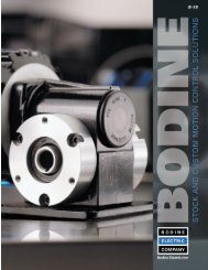
2<br />
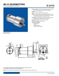
Dimensions<br />
6.900 [152]<br />
6.300 [160]<br />
0.875 [22]<br />
TB502<br />
1 2 3<br />
TB503<br />
R1<br />
5 6 7 8<br />
9 10 11 12<br />
7.780 [198]<br />
F1<br />
TB501<br />
6.000 [176]<br />
F2<br />
GND<br />
FU504<br />
L1<br />
FU503<br />
L2<br />
FU501<br />
A1<br />
A2<br />
FU502<br />
3.400 [86]<br />
0.125 [3]<br />
ALL DIMENSIONS IN INCHES [MILLIMETERS]<br />
Figure 1. <strong>RG</strong>100/200UC Dimensions
Installation<br />
3<br />
<br />
Mounting<br />
Do not install, rewire, or remove this control with input<br />
power applied. Doing so may cause fire or serious injury.<br />
Make sure you have read and understood the Safety<br />
Warnings on pg i before attempting installation.<br />
• Drive components are sensitive to electrostatic fields. Avoid<br />
direct contact with the circuit board. Hold drive by the chassis<br />
only.<br />
• Protect the drive from dirt, moisture, and accidental contact.<br />
Provide sufficient room for access to the terminal block and<br />
calibration trimpots.<br />
• Mount the drive away from heat sources. Operate the drive<br />
within the specified ambient operating temperature range.<br />
• Prevent loose connections by avoiding excessive vibration of<br />
the drive.<br />
• Mount drive with its board in either a horizontal or vertical<br />
plane. Six 0.19 in. (5 mm) wide slots in the chassis accept #8<br />
pan head screws. Fasten either the large base or the narrow<br />
flange of the chassis to the subplate.<br />
• The chassis must be earth grounded. Use a star washer beneath<br />
the head of at least one of the mounting screws to penetrate the<br />
anodized chassis surface and to reach bare metal.
4 Installation<br />
Wiring<br />
<br />
<br />
Warning<br />
Do not install, remove, or rewire this equipment with power<br />
applied. Failure to heed this warning may result in fire,<br />
explosion, or serious injury.<br />
Circuit potentials are at 115 or 230 VAC above ground. To<br />
prevent the risk of injury or fatality, avoid direct contact<br />
with the printed circuit board or with circuit elements.<br />
Do not disconnect any of the motor leads from the drive<br />
unless power is removed or the drive is disabled. Opening<br />
any one motor lead may destroy the drive.<br />
• Use 18 AWG wire for speed adjust potentiometer wiring. Use<br />
16 AWG wire for motor field (F1 and F2) wiring and 12 or 14<br />
AWG wire for motor (A1 and A2) and AC line voltage wiring<br />
(L1 and L2).
Installation<br />
5<br />
Shielding guidelines<br />
<br />
Warning<br />
Under no circumstances should power and logic leads be<br />
bundled together. Induced voltage can cause unpredictable<br />
behavior in any electronic device, including motor controls.<br />
As a general rule, Minarik recommends shielding of all<br />
conductors.<br />
If it is not practical to shield power conductors, Minarik<br />
recommends shielding all logic-level leads. If shielding is not<br />
practical, the user should twist all logic leads with themselves to<br />
minimize induced noise.<br />
It may be necessary to earth ground the shielded cable. If noise is<br />
produced by devices other than the drive, ground the shield at the<br />
drive end. If noise is generated by a device on the drive, ground<br />
the shield at the end away from the drive. Do not ground both<br />
ends of the shield.<br />
If the drive continues to pick up noise after grounding the shield,<br />
it may be necessary to add AC line filtering devices, or to mount<br />
the drive in a less noisy environment.<br />
Logic wires from other input devices, such as motion controllers<br />
and PLL velocity controllers, must be separated from power lines<br />
in the same manner as the logic I/O on this drive.
6<br />
Installation<br />
Heat sinking<br />
<strong><strong>RG</strong>100UC</strong> and <strong><strong>RG</strong>200UC</strong> drives are mounted on an external heat<br />
sink before shipment and therefore have sufficient heat sinking in<br />
their basic configurations. No additional heat sinking is<br />
necessary.<br />
Speed adjust potentiometer installation<br />
<br />
Warning<br />
Be sure that the potentiometer tabs do not make contact with<br />
the potentiometer enclosure. Grounding the input will cause<br />
damage to the drive.<br />
Speed adjust potentiometers are pre-installed on all cased drives.<br />
On chassis drives, install the circular insulating disk between the<br />
panel and the 10KΩ speed adjust potentiometer. Mount the speed<br />
adjust potentiometer through a 0.38 inch (0.96 cm) hole with the<br />
hardware provided (see Figure 2). Twist the speed adjust<br />
potentiometer wires to avoid picking up unwanted electrical<br />
noise. If potentiometer leads are longer than 18 inches (46 cm),<br />
use shielded cable. Do not bundle potentiometer wires with AC<br />
power leads.
Installation<br />
7<br />
Figure 2. Speed Adjust Potentiometer Installation
8 Installation<br />
Connections<br />
<br />
Warning<br />
Do not connect this equipment with power applied.<br />
Failure to heed this directive may result in fire or serious<br />
injury. Minarik strongly recommends the installation of<br />
a master power switch in the voltage input line, as<br />
shown in Figure 3 (page 11). The switch contacts should<br />
be rated at a minimum of 200% of motor nameplate current<br />
and 250 volts.<br />
Power, fuse and motor connections<br />
Connect the power input leads, an external line fuse and a DC<br />
motor to the drive as shown in Figure 3 on page 11.<br />
Motor<br />
Connect a DC motor to PCB terminals A1 and A2 as shown in<br />
Figure 3 on page 11. Ensure that the motor voltage rating is<br />
consistent with the drive’s output voltage.<br />
Minarik drives supply motor voltage from A1 and A2 terminals.<br />
It is assumed throughout this manual that, when A1 is positive<br />
with respect to A2 , the motor will rotate clockwise (CW) while<br />
looking at the output shaft protruding from the front of the motor.<br />
If this is opposite of the desired rotation, simply reverse the<br />
wiring of A1 and A2 with each other.
Installation<br />
9<br />
<br />
Power input<br />
Warning<br />
Minarik strongly recommends the installation of a master<br />
power switch in the voltage input line, as shown in<br />
Figure 3 (page 11). The switch contacts should be rated at a<br />
minimum of 200% of motor nameplate current and 250 volts.<br />
Connect the AC line power leads to terminals L1 and L2, or to a<br />
double-throw, single-pole master power switch (recommended).<br />
Line fuse<br />
All drives have line fuses installed (see Replacement Parts section<br />
for installed line fuse size). Line fuses are rated for maximum<br />
rated horsepower. Fuse L1 when using 115 VAC line voltage.<br />
Table 1 (page 10) lists the recommended line fuse sizes.
10<br />
Installation<br />
Table 1. Line Fuse Chart<br />
90 VDC Motor 180 VDC Max. DC Armature AC Line Fuse<br />
Horsepower Horsepower Current (amps) Size (amps)<br />
1/20 1/10 0.5 3<br />
1/15 1/8 0.8 3<br />
1/8 1/4 1.5 5<br />
1/6 1/3 1.7 5<br />
1/4 1/2 2.6 8<br />
1/3 3/4 3.5 8<br />
1/2 1 5.0 10<br />
3/4 1 1/2 7.6 15<br />
1 2 10 20<br />
Minarik Corporation offers two fuse kits: part number 050–0069<br />
(3–8A Fuse Kit) and 050–0073 (5–20A Fuse Kit). Both fuse kits<br />
include a 1/2A pico fuse (part number 050–0074) which protects<br />
the transformer and logic.
Installation<br />
11<br />
C510<br />
C501<br />
5<br />
IC501<br />
IC502<br />
C502<br />
T501<br />
6<br />
7 8<br />
2<br />
3 4<br />
FU504<br />
FU503<br />
FU501<br />
FU502<br />
1<br />
TB501<br />
7 8<br />
9 10 11 12<br />
F1<br />
F2<br />
GND<br />
L1<br />
L2<br />
A1<br />
A2<br />
MOTOR<br />
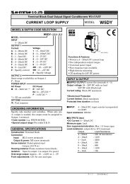
NOTE:<br />
Do not connect any wires<br />
to F1 and F2 if using a<br />
permanent-magnet motor.<br />
EME<strong>RG</strong>ENCY<br />
STOP<br />
SWITCH<br />
FIELD<br />
COILS<br />
LINE<br />
VOLTAGE<br />
INPUT<br />
Figure 3. <strong>RG</strong>100/200UC Power<br />
Connections to Terminal Board TB501
12<br />
Installation<br />
P501<br />
K501<br />
C510<br />
P502<br />
P<br />
P509<br />
IC50<br />
C501<br />
5<br />
6<br />
5<br />
6<br />
Optional Speed Adjustment Potentiometer<br />
Connections<br />
For one-way (unidirectional) operation, connect the CCW<br />
terminal of the speed pot to terminal 3 of TB502 as shown in<br />
Figure 4(a).<br />
For two-way (bidirectional) operation, connect the CCW terminal<br />
of the speed pot to terminal 6 of TB502 as shown in Figure 4(b).<br />
P501<br />
K501<br />
C510<br />
P502<br />
P50<br />
P509<br />
P<br />
IC501<br />
C501<br />
TB502<br />
TB502<br />
T<br />
1 2 3<br />
4<br />
5 6 7 8<br />
9 10 11 12<br />
1 2 3<br />
4<br />
5 6 7 8<br />
9 10 11 12<br />
CCW<br />
CW<br />
10KΩ<br />
SPEED ADJUST<br />
POTENTIOMETER<br />
CCW<br />
10KΩ<br />
SPEED ADJUST<br />
POTENTIOMETER<br />
FWD<br />
REV<br />
(a) Unidirectional direction<br />
(b) Bidirectional direction<br />
Figure 4. Speed Adjust Pot Connections
Installation<br />
13<br />
Start and Stop Switches<br />
These switches are not supplied with the control. The Start circuit<br />
requires a momentary operated normally open switch and the<br />
Stop circuit requires a momentary operated normally closed<br />
switch. Connect the switches as shown in Figure 5, page 15.<br />
When the Start switch is momentarily actuated, the motor will<br />
accelerate to set speed at a rate controlled by the FWD ACC<br />
trimpot. When the Stop switch is momentarily actuated, the motor<br />
will coast to a stop. To eliminate the Start and Stop switches,<br />
connect a jumper between terminals 10 and 12.<br />
<br />
Motor Over-Temperature Switch<br />
Warning<br />
If the O/T switch is used, the Start-Stop switches must be<br />
connected to terminals 10, 11, and 12 to prevent automatic<br />
restart of the motor. See Figure 5 (page 15) for switch<br />
connections.<br />
Some motors are available with an internal thermostat which<br />
functions as an over-temperature switch. If not used, connect a<br />
jumper between terminals 9 and 10 as shown in Figure 5,<br />
page 15.
14<br />
Installation<br />
<br />
Run/Brake Switch<br />
Warning<br />
The RUN/BRAKE switch acts as an inhibit function and will<br />
not unlatch the Start/Stop pushbutton circuit. It may not stop<br />
a drive that is malfunctioning. In order to stop the drive in<br />
an emergency, Minarik strongly suggests the installation of a<br />
stop switch, as shown in Figure 3 (page 11).<br />
The RUN/BRAKE switch is optional. When the switch is in the<br />
open position, the motor will run. When the switch is closed, the<br />
motor will be regeneratively braked to a stop. See Figure 5<br />
(page 15) for switch connections.
Installation<br />
15<br />
TB502<br />
1 2 3<br />
4<br />
5 6 7 8<br />
9 10 11 12<br />
-<br />
+<br />
TACHOGENERATOR<br />
FEEDBACK<br />
10KΩ<br />
SPEED ADJUST<br />
POTENTIOMETER<br />
RUN/STOP<br />
SWITCH<br />
CLOSE TO<br />
BRAKE<br />
MOTOR<br />
O/T<br />
SWITCH<br />
START<br />
SWITCH<br />
(N/O)<br />
STOP<br />
SWITCH<br />
(N/C)<br />
Figure 5. <strong>RG</strong>100/200UC Signal/Switch Connections<br />
to Terminal Board TB502
16<br />
Installation<br />
Field output connections<br />
<br />
Warning<br />
The field output is for shunt wound motors only. Do not<br />
make any connections to F1 and F2 when using a permanent<br />
magnet motor.<br />
Use 18 AWG wire to connect the field output to a shunt wound<br />
motor. Table 2 lists the field output connections.<br />
Table 2. Field Output Connections<br />
Line Voltage Approximate Connect Motor<br />
(VAC) Field Voltage (VDC) Field To<br />
115 50 F1 and L1<br />
115 100 F1 and F2<br />
230 100 F1 and L1<br />
230 200 F1 and F2
Operation<br />
17<br />
<br />
Warning<br />
Dangerous voltages exist on the drive when it is powered.<br />
BE ALERT. High voltages can cause serious or fatal injury.<br />
For your safety, use personal protective equipment (PPE)<br />
when operating this drive.<br />
Before Applying Power<br />
Before operating the control, carefully check that all connections<br />
are correct. Check that there are no wire chips or other foreign<br />
material on the printed circuit boards. Make sure that the input<br />
voltage is the same as listed on the control nameplate.
18 Operation<br />
Drive startup and shutdown<br />
<br />
Warning<br />
If the motor does not operate as expected, immediately<br />
remove power to the drive. Refer to the Troubleshooting<br />
section for assistance.<br />
1. Set the direction select speed adjust pot to its center position.<br />
If this pot is wired for unidirectional operation, set the pot to<br />
full CCW.<br />
2. If a RUN/BRAKE switch is used, place it in the open (run)<br />
position.<br />
3. Apply power to the drive.<br />
4. If Start and Stop pushbuttons are used, press the Start button.<br />
(If not used, terminals 10 and 12 must be jumpered.)<br />
5. Slowly turn the direction select speed adjust pot CW or CCW<br />
for the desired direction of motor rotation and speed. If the<br />
speed adjust pot is wired for unidirectional operation, slowly<br />
turn it CW to the desired speed. Verify that the motor starts<br />
slowly and increases speed in accordance with the<br />
potentiometer setting.<br />
6. To shut down the drive, set the speed adjust pot to its center<br />
position (zero speed). (If the drive is wired for unidirectional<br />
operation, turn the speed adjust pot full CCW.) Press the<br />
STOP pushbutton (if installed).
Operation<br />
19<br />
Tachogenerator Feedback<br />
Tachogenerator feedback is optional. Without tachogenerator<br />
feedback, load regulation is approximately 2% of base speed with<br />
a speed range of 30 to 1. This is quite acceptable for most<br />
applications which do not involve sizable load changes. With<br />
tachogenerator feedback, load regulation is better than 0.5% of<br />
base speed with a speed range of 50 to 1.<br />
Calculating the Feedback Resistor Value<br />
The following steps are required to convert the control to operate<br />
in a closed-loop, tachogenerator mode.<br />
1. The control is factory set for a tachogenerator rated at 50 volts<br />
per 1000 RPM, with a maximum motor speed of 1800 RPM. If<br />
the tachogenerator output is other than 50 volts per 1000 RPM,<br />
or the maximum speed is greater than 1800 RPM, calculate the<br />
value of R1 based upon Vmax, the tachogenerator output<br />
voltage at maximum motor speed. Note that Vmax must be at<br />
or greater than 5 volts.
20 Operation<br />
The following equation should be used to properly size the tach<br />
feedback resistor, based upon the tachogenerator volts per rpm<br />
output and the maximum tachometer speed allowed by the<br />
application:<br />
R 1 =<br />
[(V/rpm X RPMmax) – 5]<br />
2.3<br />
Kohms<br />
where R1 is the feedback resistor size in K ohms, V/rpm is the<br />
tach output rating and RPMmax is the maximum tach speed<br />
allowed.<br />
For example, assume you are using a tachogenerator with an<br />
output of 50 volts per 1000 RPM , with a maximum speed of<br />
1800 RPM. Applying the feedback resistor equation, we find:<br />
V/rpm = 50V ÷ 1000 RPM = .05<br />
RPMmax = 1800<br />
R 1 = [(.05 x 1800) – 5] ÷ 2.3 = 36.9 Kohms<br />
Therefore, a 36.9K ohm resistor is required.<br />
Select a standard 1/4 watt resistor of the calculated value and<br />
install this resistor on terminal board TB3. If the calculated value<br />
is not available, select the next higher standard resistance and,<br />
after steps 3 and 4 have been followed, use the MAX SPD ADJ<br />
trimpot to set the maximum speed. See page 29 for information<br />
on calibrating the MAX SPD ADJ trimpot.
Operation<br />
21<br />
2. Set the IR COMP trim pot fully CCW.<br />
3. Connect the tachogenerator leads to terminals 1 (negative) and<br />
2 (positive) on terminal board TB502. Tachogenerator polarity<br />
is that produced with motor running in FORWARD direction.<br />
If any doubt exists concerning the tachogenerator polarity, start<br />
the motor very slowly. A miswired tachogenerator will cause the<br />
motor to accelerate to full speed. If this occurs, disconnect the<br />
control from AC power immediately. Interchange the connections<br />
at terminals 1 and 2. Reconnect AC power to the control.
22 Operation<br />
Line Starting and Line Stopping<br />
<br />
Warning<br />
Decelerating to minimum speed, regenerative braking, or<br />
coasting to a stop is recommended for frequent starts and<br />
stops. Do not use any of these methods for emergency<br />
stopping. They may not stop a drive that is malfunctioning.<br />
Removing AC line power (both L1 and L2) is the only<br />
acceptable method for emergency stopping.<br />
For this reason, Minarik strongly recommends installing<br />
an emergency stop switch on both the L1 and L2 inputs<br />
(see Connections - page 8).<br />
Connect a jumper between terminals 9 and 12. When AC line<br />
power is removed, the motor will coast to a stop. When power is<br />
re-applied, the motor will accelerate to the set speed at a rate<br />
determined by the ACCEL trimpot setting.
Calibration<br />
<br />
Warning<br />
Dangerous voltages exist on the drive when it is powered.<br />
When possible, disconnect the voltage input from the drive<br />
before adjusting the trimpots. If the trimpots must be<br />
adjusted with power applied, use insulated tools and the<br />
appropriate personal protection equipment. BE ALERT.<br />
High voltages can cause serious or fatal injury.<br />
Each drive is factoy calibrated to its maximum current rating.<br />
Readjust the calibration trimpot settings to accommodate lower<br />
current rated motors. All adjustments increase with CW rotation,<br />
and decrease with CCW rotation. Refer to Figure 6 (page 24) for<br />
trimpot location.<br />
23
24 Calibration<br />
MAXIMUM<br />
SPEED<br />
DEADBAND<br />
IR COMP<br />
CURRENT<br />
STABILIZATION<br />
FORWARD<br />
ACCELERATION<br />
REVERSE<br />
ACCELERATION<br />
FORWARD<br />
TORQUE<br />
REVERSE<br />
TORQUE<br />
VOLTAGE<br />
STAB<br />
Figure 6. Calibration Trimpot Layout
Calibration<br />
25<br />
FWD TQ<br />
<br />
Warning<br />
Although FORWARD TORQUE should be set to 120% of<br />
drive nameplate current rating, continuous operation beyond<br />
this rating may damage the motor. If you intend to operate<br />
beyond the rating, contact your Minarik representative for<br />
assistance.<br />
The FWD TQ setting determines the maximum torque for<br />
accelerating and driving the motor in the forward direction. It also<br />
sets the maximum torque for decelerating the motor in the reverse<br />
direction. Refer to Figure 8 (page 31) for recommended FWD<br />
TQ settings or recalibrate using the following procedure:<br />
1. With the power disconnected from the drive, connect a DC<br />
ammeter in series with the armature.<br />
2. Set the FWD TQ trimpot to minimum (full CCW).<br />
3. Set the speed adjust potentiometer to maximum forward speed.<br />
4. Lock the motor shaft. Be sure that the motor is firmly mounted<br />
to withstand maximum torque generated by the motor.<br />
5. Apply line power. The motor should be stopped.<br />
6. Slowly adjust the FWD TQ trimpot CW until the armature<br />
current is 120% of motor rated armature current.<br />
7. Set the speed adjust potentiometer to minimum.<br />
8. Remove the power from the drive and unlock the motor shaft.<br />
9. Remove the ammeter in series with the motor armature if it is<br />
no longer needed and re-apply power to the drive.
26<br />
Calibration<br />
REV TQ<br />
<br />
Warning<br />
Although REVERSE TORQUE should be set to 120% of<br />
drive nameplate current rating, continuous operation beyond<br />
this rating may damage the motor. If you intend to operate<br />
beyond the rating, contact your Minarik representative for<br />
assistance.<br />
The REV TQ setting determines the maximum torque for<br />
accelerating and driving the motor in the reverse direction. It also<br />
sets the maximum torque for decelerating in the forward<br />
direction. Refer to Figure 8 (page 31) for recommended REV TQ<br />
settings or recalibrate using the following procedure:<br />
1. With the power disconnected from the drive, connect a DC<br />
ammeter in series with the armature.<br />
2. Set the REV TQ trimpot to minimum (full CCW).<br />
3. Set the speed adjust potentiometer to maximum reverse speed.<br />
4. Lock the motor shaft. Be sure that the motor is firmly mounted<br />
to withstand maximum torque generated by the motor.<br />
5. Apply line power. The motor should be stopped.<br />
6. Slowly adjust the REV TQ trimpot CW until the armature<br />
current is 120% of motor rated armature current.<br />
7. Set the speed adjust potentiometer to minimum.<br />
8. Remove the power from the drive and unlock the motor shaft.<br />
9. Remove the ammeter in series with the motor armature if it is<br />
no longer needed and re-apply power to the drive.
Calibration<br />
27<br />
IR COMP<br />
The IR COMP trimpot setting determines the degree to which<br />
motor speed is held constant as the motor load changes. It is<br />
factory set for optimum motor regulation.<br />
Use the following procedure to recalibrate the IR COMP setting:<br />
1. Set the IR COMP trimpot to minimum (full CCW).<br />
2. Rotate the speed adjust potentionmeter until the motor runs at<br />
midspeed without load (for example, 900 RPM for an 1800<br />
RPM motor). A hand held tachometer may be used to<br />
measure motor speed.<br />
3. Load the motor armature to its full load armature current<br />
rating. The motor should slow down.<br />
4. While keeping the load on the motor, rotate the IR COMP<br />
trimpot until the motor runs at the speed measured in step 2.<br />
If the motor oscillates (overcompensation), the IR COMP<br />
trimpot may be set too high (CW). Turn the IR COMP trimpot<br />
CCW to stabilize the motor.<br />
5. Unload the motor.
28 Calibration<br />
FWD ACC<br />
The FWD ACC setting determines the time the motor takes to<br />
ramp to either a higher speed in the forward direction or a lower<br />
speed in the reverse direction, within the limits of available<br />
torque. The FWD ACC setting is factory set for its fastest forward<br />
acceleration time.<br />
Turn the FWD ACC trimpot CW to increase the forward<br />
acceleration time, and CCW to decrease the forward acceleration<br />
time.<br />
REV ACC<br />
The REV ACC setting determines the time the motor takes to<br />
ramp to either a higher speed in the reverse direction or a<br />
lower speed in the forward direction, within the limits of available<br />
torque. The REV ACC setting is factory set for its fastest reverse<br />
acceleration time.<br />
Turn the REV ACC trimpot CW to increase the reverse<br />
acceleration time, and CCW to decrease the reverse acceleration<br />
time.
Calibration<br />
29<br />
MAX SPD<br />
DB<br />
The MAX SPD setting determines the maximum motor speed<br />
when the speed adjust potentiometer is turned full CW. It is<br />
factory set for maximum rated voltage.<br />
To calibrate MAX SPD:<br />
1. Set the MAX trimpot full CCW.<br />
2. Turn the speed adjust potentiometer full CW.<br />
3. Adjust the MAX SPD trimpot until the desired maximum<br />
motor speed is reached.<br />
The deadband (DB) trimmer potentiometer determines the time<br />
that will elapse between the application of current in one direction<br />
before current is applied in the opposite direction.<br />
The deadband trimmer potentiometer affects the resistance that a<br />
motor has to changes in shaft position at zero speed. It does this<br />
by applying AC voltage to the motor armature.<br />
Deadband is factory calibrated to approximately the<br />
3 o’clock position for 60 Hz AC line operation. Recalibrate<br />
the deadband to the 9 o’clock position for 50 Hz AC line<br />
operation. See Figure 8 (page 31) for deadband settings.
30 Calibration<br />
CURRENT STAB<br />
The effect of this adjustment is most apparent in the DC<br />
tachogenerator feedback operating mode. CURRENT STAB is<br />
factory set to midrange and should not require adjustment unless<br />
the tachogenerator signal has considerable ripple. Then, you<br />
should turn this trim pot CW until the motor stabilizes.<br />
VOLTAGE STAB<br />
The effect of this trim pot is most obvious when tachogenerator<br />
feedback is used. When optimum adjustment of voltage<br />
stabilization is achieved, the speed profile through time should be<br />
smooth (Figure A). If the trimpot is set too low, stepping will<br />
occur during acceleration and deceleration. It will be especially<br />
obvious in the Decel mode (Figure B). If the trimpot is set too<br />
high, you may see oscillation at a given set speed (Figure C).<br />
VOLTAGE STAB is factory set to midrange.<br />
Figure 7. Voltage Stabilization Outputs
Calibration<br />
31<br />
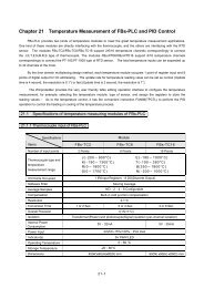
FWD TORQUE and REV TORQUE SETTINGS<br />
<strong><strong>RG</strong>100UC</strong><br />
<strong><strong>RG</strong>200UC</strong><br />
REV<br />
TORQUE<br />
FWD<br />
TORQUE<br />
BOARD<br />
EDGE<br />
1/4 HP<br />
1750 RPM<br />
90 VDC<br />
2.7 AMP<br />
REV<br />
TORQUE<br />
FWD<br />
TORQUE<br />
BOARD<br />
EDGE<br />
1/2 HP<br />
1750 RPM<br />
180 VDC<br />
2.5 AMP<br />
REV<br />
TORQUE<br />
FWD<br />
TORQUE<br />
BOARD<br />
EDGE<br />
1/2 HP<br />
1750 RPM<br />
90 VDC<br />
5.0 AMP<br />
REV<br />
TORQUE<br />
FWD<br />
TORQUE<br />
BOARD<br />
EDGE<br />
1 HP<br />
1750 RPM<br />
180 VDC<br />
5.0 AMP<br />
REV<br />
TORQUE<br />
FWD<br />
TORQUE<br />
BOARD<br />
EDGE<br />
1 HP<br />
1750 RPM<br />
90 VDC<br />
10.0 AMP<br />
REV<br />
TORQUE<br />
FWD<br />
TORQUE<br />
BOARD<br />
EDGE<br />
2 HP<br />
1750 RPM<br />
180 VDC<br />
9.2 AMP<br />
DEADBAND (DB) SETTINGS<br />
60 Hz<br />
Applications<br />
50 Hz<br />
Applications<br />
DB<br />
DB<br />
Figure 8. Recommended FWD TORQUE,<br />
REV TORQUE and DB Settings
32<br />
Troubleshooting<br />
<br />
Warning<br />
Dangerous voltages exist on the drive when it is powered.<br />
When possible, disconnect the drive while troubleshooting.<br />
High voltages can cause serious or fatal injury.<br />
Before troubleshooting<br />
Perform the following steps before starting any procedure in this<br />
section:<br />
1. Disconnect AC line voltage from the drive.<br />
2. Check the drive closely for damaged components.<br />
3. Check that no conductive or other foreign material has become<br />
lodged on the printed circuit board.<br />
4. Verify that every connection is correct and in good condition.<br />
5. Verify that there are no short circuits or grounded connections.<br />
6. Check that the drive’s rated armature outputs are consistent<br />
with the motor ratings.<br />
For additional assistance, contact your local Minarik® distributor,<br />
or the factory direct at:<br />
(800) MINARIK (phone) or (775) 823-9495 (fax).
Troubleshooting<br />
33<br />
Problem<br />
Possible<br />
Causes<br />
Suggested<br />
Solutions<br />
Field fuse blows<br />
Line fuse blows<br />
1. Field fuse is the wrong<br />
size.<br />
2. Motor field is shorted to<br />
ground.<br />
3. F1 is shorted to F2.<br />
4. Motor cable is shorted<br />
to ground.<br />
5. Motor field leads are<br />
reversed with motor<br />
armature.<br />
1. Line fuses are the wrong<br />
size.<br />
2. Motor cable or armature<br />
is shorted to ground.<br />
3. Field circuit is open.<br />
4. Nuisance tripping<br />
caused by a combination<br />
of ambient conditions<br />
and high-current spikes<br />
(i.e. reversing).<br />
1. Verify that the fuse is 3<br />
ADC.<br />
2. Check if the motor field<br />
is shorted to ground.<br />
Replace motor if<br />
necessary.<br />
3. Check that F1 and F2<br />
are not shorted together.<br />
4. Check that the motor<br />
cable is not shorted to<br />
ground. Replace cable if<br />
necessary.<br />
5. Wire motor armature to<br />
Al and A2; wire motor<br />
field to F1 and F2.<br />
1. Check that line fuses are<br />
15 A.<br />
2. Check motor cable and<br />
armature for shorts.<br />
3. Send in drive to Minarik<br />
repair department.<br />
4. Add a blower to cool<br />
the drive components;<br />
increase FWD TQ and<br />
REV TQ settings. See<br />
pages 25 and 26.
34 Troubleshooting<br />
Problem<br />
Possible<br />
Causes<br />
Suggested<br />
Solutions<br />
Motor runs too fast at<br />
maximum speed setting<br />
Line fuse does not blow,<br />
but the motor does not<br />
run<br />
1. MAX SPD setting is too<br />
high.<br />
2. Motor field connections<br />
are loose (shunt wound<br />
motors only).<br />
1. Speed adjust pot or<br />
voltage input signal set<br />
to zero speed.<br />
2. Speed adjust pot or<br />
voltage input signal not<br />
connected to drive input<br />
properly; connections<br />
are open.<br />
3. REGEN BRAKE is<br />
jumpered.<br />
4. S2 is shorted to S0.<br />
5. Drive is in current limit.<br />
6. Drive is not receiving<br />
AC line voltage.<br />
1. Recalibrate MAX SPD.<br />
See page 29.<br />
2. Check motor field<br />
connections.<br />
1. Increase the speed<br />
adjust potentiometer,<br />
voltage, or current<br />
setting.<br />
2. Check connections to<br />
input. Verify that<br />
connections are not<br />
open.<br />
3. Remove jumper from<br />
REGEN BRAKE<br />
terminal.<br />
4. Remove short.<br />
5. Verify that motor is not<br />
jammed. Increase FWD<br />
TQ or REV TQ setting<br />
if they are set too low.<br />
See pages 25 and 26.<br />
6. Apply AC line voltage<br />
to L1 and L2.
Troubleshooting<br />
35<br />
Problem<br />
Possible<br />
Causes<br />
Suggested<br />
Solutions<br />
Motor runs too slow or<br />
too fast<br />
Motor will not reach the<br />
desired speed<br />
Motor pulsates or surges<br />
under load<br />
Motor does not reverse<br />
1. Switches set incorrectly.<br />
2. MAX SPD not<br />
calibrated.<br />
3. Motor field not properly<br />
connected (shunt wound<br />
motors only).<br />
1. MAX SPD setting is too<br />
low.<br />
2. IR COMP setting is too<br />
low.<br />
1. IR COMP is set too<br />
high.<br />
2. Motor "bouncing" in<br />
and out of torque limit.<br />
1. Bad speed pot<br />
connection to TB502.<br />
2. Reversing circuit not<br />
working properly.<br />
1. Verify all switch<br />
settings.<br />
2. Calibrate MAX SPD.<br />
See page 29.<br />
3. Verify motor field<br />
connections.<br />
1. Increase MAX SPD<br />
setting. See page 29.<br />
2. Increase the IR COMP<br />
setting. See page 27.<br />
1. Adjust the IR COMP<br />
setting slightly CCW<br />
until the motor speed<br />
stabilizes. See page 27.<br />
2. Make sure motor is not<br />
undersized for load;<br />
adjust FWD TQ and<br />
REV TQ trimpots. See<br />
pages 25 and 26.<br />
1. Check pot connection to<br />
TB502.<br />
2. Check reversing circuit<br />
by shorting TB502-5 to<br />
TB502-6 with jumper<br />
wire.
36 Troubleshooting<br />
Problem<br />
Possible<br />
Causes<br />
Suggested<br />
Solutions<br />
Motor makes a<br />
humming or buzzing<br />
noise<br />
1. Deadband setting is too<br />
high.<br />
1. Turn deadband (DB)<br />
trimpot CCW until the<br />
noise stops. See page<br />
29.
Troubleshooting<br />
37<br />
Replacement Parts<br />
Replacement parts are available from Minarik Corporation and its<br />
distributors for this drive series.<br />
Table 3. Replacement Parts<br />
Model No. Symbol Description Minarik P/N<br />
<strong><strong>RG</strong>100UC</strong> C501 - 502 Capacitor, 470 uF 50V 011-0056<br />
IC501 LM340T12 Regulator 061-0019<br />
IC502 LM320T12 Regulator 061-0020<br />
SCR501 - 508 S8025L SCR 072-0042<br />
TB501 7-Pin Terminal Block 160-0019<br />
TB502 12-Pin Terminal Block 160-0086<br />
T501 115:36 Transformer 230-0071<br />
<strong><strong>RG</strong>200UC</strong><br />
Same as above, except:<br />
T501 115/230 Transformer 230-0072<br />
All models Fuse Kit, 5 – 20A 050-0073<br />
Pot Kit, 10K Ohm/5W 202-0003
38<br />
Certificate of Compliance<br />
Minarik Corporation hereby certifies that its <strong>RG</strong>100/<strong>RG</strong>200<br />
Series drives have been approved to bear the “CE” mark provided<br />
the conditions of approval have been met by the end user.<br />
The <strong>RG</strong>100/<strong>RG</strong>200 Series drives have been tested to the<br />
following test specifications:<br />
EN55011:1991 (emissions), and<br />
EN50082-1:1992 (immunity)<br />
Compliance allows the <strong>RG</strong>100/<strong>RG</strong>200 Series drives to bear the<br />
CE mark.<br />
End User Responsibilities<br />
The end user, as described herein, falls into one of two categories:<br />
1. The Consumer will deploy a stand-alone unit as an<br />
integral, yet external, portion of the machine being<br />
operated.<br />
2. The Original Equipment Manufacturer (OEM) will<br />
implement the product as a component of the machine<br />
being manufactured.
CE Compliance<br />
39<br />
AC Line Filters<br />
In addition to EMI/RFI safeguards inherent in the <strong>RG</strong>100/<strong>RG</strong>200<br />
design, external filtering is required.<br />
Minarik requires the Corcom® AC line filters listed in Table 4.<br />
Use model 6VV1 with drives rated for 3 ADC or below, and<br />
model 20VV1 with drives rated for 10 ADC or below.<br />
Table 4. AC Line Filters<br />
Corcom ® Model Number 6VV1 20VV1<br />
Rated Current 6 A 20 A<br />
Inductance 1.8 mH 1.8 mH<br />
Capacitance<br />
Line to Line 0.8 mF 1.1 mF<br />
Line to Ground 0.01 mF 0.01 mF<br />
Discharge Resistor 330 Kohms 330 Kohms<br />
Wire the AC line filter within 0.25 meters of the<br />
drive. The ground connection from the filter must be<br />
wired to solid earth ground (resistance less than 500<br />
ohms); not machine ground. This is very important!<br />
If the end-user is using a CE-approved motor, the<br />
correct filter from Table 4 is all that is necessary to meet the EMC<br />
directives listed herein.
40 CE Compliance<br />
Armature Filters<br />
If the end-user is not using a CE-approved motor, a second filter<br />
on the armature must be deployed. See Table 5 for recommended<br />
armature filters. Use model CE04<strong>RG</strong> with drives rated for 3 ADC<br />
or below, and model CE20<strong>RG</strong> with drives rated for 20 ADC or<br />
below.<br />
Table 5. Armature Filters<br />
Minarik ® Model Number CE04<strong>RG</strong> CE20<strong>RG</strong><br />
Rated Current 4 A 20 A<br />
Inductance<br />
1200 mH<br />
Capacitance (C1 and C2)<br />
0.1 mF @ 400W VDC<br />
Discharge Resistor<br />
680KW<br />
Wire the armature filter to the DC output of the<br />
drive, as close to the drive as possible. The ground<br />
connection from the filter must be wired to solid<br />
earth ground (resistance less than 500 ohms); not<br />
machine ground. This is very important!<br />
The end user must use the filtration listed in this addendum to<br />
comply with CE. The OEM may choose to provide alternative<br />
filtering that encompasses the Minarik drive and other electronics<br />
within the same panel.The OEM has this liberty because CE is a<br />
machinery directive.
CE Compliance<br />
41<br />
Whether or not every component in the OEM’s machinery<br />
meets CE, the OEM must still submit his machine for CE<br />
approval. Thus, no component must necessarily meet CE within<br />
the machine, as long as the OEM takes the necessary steps to<br />
guarantee the machine does meet CE. By the same token, even if<br />
every component in the OEM’s machine does meet CE, the<br />
machine will not necessarily meet CE as a machine.<br />
Using CE-approved wiring practices (like proper shielding)<br />
and the filters should assure the drive will meet EN55014 (1993<br />
emissions standard) and EN50082-1 (1992 immunity standard).
42<br />
Index<br />
Calibration 23<br />
CURRENT STAB 30<br />
DB 29<br />
FWD ACC 28<br />
FWD TQ 25<br />
IR COMP 27<br />
MAX SPD 29<br />
REV ACC 28<br />
REV TQ 26<br />
VOLTAGE STAB 30<br />
Certificate of Compliance 38<br />
AC Line Filters 39<br />
Armature Filters 40<br />
End User Responsibilities 38<br />
Dimensions 2<br />
Installation 3<br />
Connections 8<br />
Field output connections 16<br />
Motor Over-Temperature Switch 13<br />
Optional Speed Adjustment Potentiometer Connections 12<br />
Power, fuse and motor connections 8<br />
Line fuse 9<br />
Motor 8<br />
Power input 9<br />
Run/Brake Switch 14
43<br />
Start and Stop Switches 13<br />
Heat sinking 6<br />
Mounting 3<br />
Speed adjust potentiometer installation 6<br />
Wiring 4<br />
Shielding guidelines 5<br />
Operation 17<br />
Before Applying Power 17<br />
Drive startup and shutdown 18<br />
Line Starting and Line Stopping 22<br />
Tachogenerator Feedback 19<br />
Calculating the Feedback Resistor Value 19<br />
Safety Warnings i<br />
Specifications 1<br />
Troubleshooting 32<br />
Replacement Parts 37<br />
Unconditional Warranty 44
Notes
Unconditional Warranty<br />
A. Warranty<br />
Minarik Corporation (referred to as "the Corporation") warrants that its products will be<br />
free from defects in workmanship and material for twelve (12) months or 3,000 hours,<br />
whichever comes first, from date of manufacture thereof. Within this warranty period,<br />
the Corporation will repair or replace, at its sole discretion, such products that are<br />
returned to Minarik Corporation, 901 East Thompson Avenue, Glendale, CA 91201-<br />
2011 USA.<br />
This warranty applies only to standard catalog products, and does not apply to<br />
specials. Any returns for special controls will be evaluated on a case-by-case basis.<br />
The Corporation is not responsible for removal, installation, or any other incidental<br />
expenses incurred in shipping the product to and from the repair point.<br />
B. Disclaimer<br />
The provisions of Paragraph A are the Corporation's sole obligation and exclude all<br />
other warranties of merchantability for use, express or implied. The Corporation further<br />
disclaims any responsibility whatsoever to the customer or to any other person for<br />
injury to the person or damage or loss of property of value caused by any product that<br />
has been subject to misuse, negligence, or accident, or misapplied or modified by<br />
unauthorized persons or improperly installed.<br />
C. Limitations of Liability<br />
In the event of any claim for breach of any of the Corporation's obligations, whether<br />
express or implied, and particularly of any other claim or breech of warranty contained<br />
in Paragraph A, or of any other warranties, express or implied, or claim of liability that<br />
might, despite Paragraph B, be decided against the Corporation by lawful authority, the<br />
Corporation shall under no circumstances be liable for any consequential damages,<br />
losses, or expense arising in connection with the use of, or inability to use, the<br />
Corporation's product for any purpose whatsoever.<br />
An adjustment made under warranty does not void the warranty, nor does it imply an<br />
extension of the original 12-month warranty period. Products serviced and/or parts<br />
replaced on a no-charge basis during the warranty period carry the unexpired portion<br />
of the original warranty only.<br />
If for any reason any of the foregoing provisions shall be ineffective, the Corporation's<br />
liability for damages arising out of its manufacture or sale of equipment, or use thereof,<br />
whether such liability is based on warranty, contract, negligence, strict liability in tort, or<br />
otherwise, shall not in any event exceed the full purchase price of such equipment.<br />
Any action against the Corporation based upon any liability or obligation arising<br />
hereunder or under any law applicable to the sale of equipment or the use thereof,<br />
must be commenced within one year after the cause of such action arises.
901 E Thompson Avenue<br />
Glendale, CA 91201-2011<br />
Tel.: 1-800-MINARIK (646-2745)<br />
Fax: 1-800-394-6334<br />
www.minarikcorp.com<br />
Document Number 250-0096, Revision 4<br />
Printed in the U.S.A – 12/00<br />
U.S.A. $10.00, Outside U.S.A. $11.00