User's Manual - Alstron
User's Manual - Alstron
User's Manual - Alstron

You also want an ePaper? Increase the reach of your titles
YUMPU automatically turns print PDFs into web optimized ePapers that Google loves.
MMXL Series<br />
Models:<br />
MMXL02–D240AC<br />
MMXL05–D240AC<br />
MMXL10–D240AC<br />
MMXL02–D240AC-PCM<br />
MMXL05–D240AC-PCM<br />
MMXL10–D240AC-PCM<br />
User’s <strong>Manual</strong><br />
Pulse-Width Modulated, Adjustable Speed<br />
Drives for DC Brush Motors
Copyright © 2002 by<br />
Minarik Corporation<br />
All rights reserved. No part of this manual may be reproduced or transmitted in any<br />
form without written permission from Minarik Corporation. The information and<br />
technical data in this manual are subject to change without notice. Minarik<br />
Corporation and its Divisions make no warranty of any kind with respect to this<br />
material, including, but not limited to, the implied warranties of its merchantability<br />
and fitness for a given purpose. Minarik Corporation and its Divisions assume no<br />
responsibility for any errors that may appear in this manual and make no<br />
commitment to update or to keep current the information in this manual.<br />
Printed in the United States of America.
i<br />
Safety Warnings<br />
SHOCK<br />
HAZARD<br />
AVOID<br />
HEAT<br />
KEE<br />
DR<br />
OID<br />
ATION<br />
• This symbol denotes an important safety tip or warning.<br />
Please read these instructions carefully before performing<br />
any of the procedures contained in this manual.<br />
• DO NOT INSTALL, REMOVE, OR REWIRE THIS<br />
EQUIPMENT WITH POWER APPLIED. Have a qualified<br />
electrical technician install, adjust and service this equipment.<br />
Follow the National Electrical Code and all other applicable<br />
electrical and safety codes, including the provisions of the<br />
Occupational Safety and Health Act (OSHA), when installing<br />
equipment.<br />
• Reduce the chance of an electrical fire, shock, or explosion by<br />
proper grounding, over-current protection, thermal protection,<br />
and enclosure. Follow sound maintenance procedures.<br />
<br />
It is possible for a drive to run at full speed as a result of a<br />
component failure. Minarik strongly recommends the<br />
installation of a master switch in the main power input to stop<br />
the drive in an emergency.<br />
Circuit potentials are at 115 VAC or 230 VAC above earth<br />
ground. Avoid direct contact with the printed circuit board or<br />
with circuit elements to prevent the risk of serious injury or<br />
fatality. Use a non-metallic screwdriver for adjusting the<br />
calibration trimpots. Use approved personal protective<br />
equipment and insulated tools if working on this drive with<br />
power applied.
ii<br />
Contents<br />
Safety Warnings<br />
i<br />
Specifications 1<br />
Dimensions 2<br />
Installation 4<br />
Mounting . . . . . . . . . . . . . . . . . . . . . . . . . . . . . . . . . . . . . . . . . . . . . . . . . . . . .4<br />
Wiring . . . . . . . . . . . . . . . . . . . . . . . . . . . . . . . . . . . . . . . . . . . . . . . . . . . . . . .5<br />
Shielding guidelines . . . . . . . . . . . . . . . . . . . . . . . . . . . . . . . . . . . . . . . . . .6<br />
Heat sinking . . . . . . . . . . . . . . . . . . . . . . . . . . . . . . . . . . . . . . . . . . . . . . . . . .7<br />
Line fusing . . . . . . . . . . . . . . . . . . . . . . . . . . . . . . . . . . . . . . . . . . . . . . . . . . .7<br />
Speed adjust potentiometer . . . . . . . . . . . . . . . . . . . . . . . . . . . . . . . . . . . . . . .9<br />
Isolation . . . . . . . . . . . . . . . . . . . . . . . . . . . . . . . . . . . . . . . . . . . . . . . . . . . .10<br />
Connections . . . . . . . . . . . . . . . . . . . . . . . . . . . . . . . . . . . . . . . . . . . . . . . . .11<br />
Power, fuse and motor connections . . . . . . . . . . . . . . . . . . . . . . . . . . . . .11<br />
Master power switch . . . . . . . . . . . . . . . . . . . . . . . . . . . . . . . . . . . . . .11<br />
Motor . . . . . . . . . . . . . . . . . . . . . . . . . . . . . . . . . . . . . . . . . . . . . . . . .12<br />
Power input . . . . . . . . . . . . . . . . . . . . . . . . . . . . . . . . . . . . . . . . . . . . .12<br />
Line fuse . . . . . . . . . . . . . . . . . . . . . . . . . . . . . . . . . . . . . . . . . . . . . . .12<br />
Voltage follower . . . . . . . . . . . . . . . . . . . . . . . . . . . . . . . . . . . . . . . . . . . . . .14<br />
Operation 15<br />
Before applying power . . . . . . . . . . . . . . . . . . . . . . . . . . . . . . . . . . . . . . . . .15<br />
Startup . . . . . . . . . . . . . . . . . . . . . . . . . . . . . . . . . . . . . . . . . . . . . . . . . . . . .16<br />
Starting and Stopping Methods . . . . . . . . . . . . . . . . . . . . . . . . . . . . . . . . . . .17<br />
Line starting and line stopping . . . . . . . . . . . . . . . . . . . . . . . . . . . . . . . . .17<br />
Automatic restart upon power restoration . . . . . . . . . . . . . . . . . . . . . . . . .18<br />
Inhibit terminals . . . . . . . . . . . . . . . . . . . . . . . . . . . . . . . . . . . . . . . . . . . . .18
Contents<br />
iii<br />
Inhibit plug . . . . . . . . . . . . . . . . . . . . . . . . . . . . . . . . . . . . . . . . . . . . . . . .19<br />
Decelerating to minimum speed . . . . . . . . . . . . . . . . . . . . . . . . . . . . . . . .20<br />
Dynamic braking . . . . . . . . . . . . . . . . . . . . . . . . . . . . . . . . . . . . . . . . . . . .21<br />
RUN/BRAKE switch . . . . . . . . . . . . . . . . . . . . . . . . . . . . . . . . . . . . . . .21<br />
Dynamic brake resistor sizes . . . . . . . . . . . . . . . . . . . . . . . . . . . . . . . .21<br />
Calibration 23<br />
Calibration procedure . . . . . . . . . . . . . . . . . . . . . . . . . . . . . . . . . . . . . . . . . .24<br />
Before applying power . . . . . . . . . . . . . . . . . . . . . . . . . . . . . . . . . . . . . . .24<br />
MINIMUM SPEED (MIN SPD) . . . . . . . . . . . . . . . . . . . . . . . . . . . . . . . . .25<br />
MAXIMUM SPEED (MAX SPD) . . . . . . . . . . . . . . . . . . . . . . . . . . . . . . . .25<br />
ACCELERATION (ACCEL) . . . . . . . . . . . . . . . . . . . . . . . . . . . . . . . . . . .26<br />
DECELERATION (DECEL) . . . . . . . . . . . . . . . . . . . . . . . . . . . . . . . . . . .26<br />
REGULATION (IR COMP) . . . . . . . . . . . . . . . . . . . . . . . . . . . . . . . . . . . .27<br />
CURRENT LIMIT (CURR LIM) . . . . . . . . . . . . . . . . . . . . . . . . . . . . . . . . .28<br />
Application Notes 34<br />
Multiple fixed speeds . . . . . . . . . . . . . . . . . . . . . . . . . . . . . . . . . . . . . . . . . .34<br />
Adjustable speeds using potentiometers in series . . . . . . . . . . . . . . . . . . . . .35<br />
Independent adjustable speeds . . . . . . . . . . . . . . . . . . . . . . . . . . . . . . . . . .36<br />
RUN/JOG switch . . . . . . . . . . . . . . . . . . . . . . . . . . . . . . . . . . . . . . . . . . . . .37<br />
RUN/JOG option #1 . . . . . . . . . . . . . . . . . . . . . . . . . . . . . . . . . . . . . . . . .37<br />
RUN/JOG option #2 . . . . . . . . . . . . . . . . . . . . . . . . . . . . . . . . . . . . . . . . .38<br />
Leader-follower application . . . . . . . . . . . . . . . . . . . . . . . . . . . . . . . . . . . . . .39<br />
Single speed potentiometer control of multiple drives (-PCM models only) . .40<br />
Reversing . . . . . . . . . . . . . . . . . . . . . . . . . . . . . . . . . . . . . . . . . . . . . . . . . . .41<br />
Reversing with a DIGI-LOK controller . . . . . . . . . . . . . . . . . . . . . . . . . . . . . .42
iv<br />
Contents<br />
Troubleshooting 43<br />
Before troubleshooting . . . . . . . . . . . . . . . . . . . . . . . . . . . . . . . . . . . . . . . . .43<br />
Diagnostic LEDs . . . . . . . . . . . . . . . . . . . . . . . . . . . . . . . . . . . . . . . . . . . . . .44<br />
POWER . . . . . . . . . . . . . . . . . . . . . . . . . . . . . . . . . . . . . . . . . . . . . . . . . .44<br />
CURRENT LIMIT (CL/FLT) . . . . . . . . . . . . . . . . . . . . . . . . . . . . . . . . . . . .44<br />
Replacement Parts . . . . . . . . . . . . . . . . . . . . . . . . . . . . . . . . . . . . . . . . . . . .48<br />
Certificate of Compliance 50<br />
CE Certification . . . . . . . . . . . . . . . . . . . . . . . . . . . . . . . . . . . . . . . . . . . . . .50<br />
AC Line Filters . . . . . . . . . . . . . . . . . . . . . . . . . . . . . . . . . . . . . . . . . . . . . . .51<br />
Unconditional Warranty<br />
inside back cover
v<br />
Illustrations<br />
Figure 1. MMXL Dimensions . . . . . . . . . . . . . . . . . . . . . . . . . . . . . . . . . . . . . . . .2<br />
Figure 2. MMXL10 Drive Dimensions With Heat Sink Installed . . . . . . . . . . . . . .3<br />
Figure 3. Speed Adjust Potentiometer . . . . . . . . . . . . . . . . . . . . . . . . . . . . . . . . .9<br />
Figure 4. MMXL Series Connections . . . . . . . . . . . . . . . . . . . . . . . . . . . . . . . . .13<br />
Figure 5. Voltage Follower Connections . . . . . . . . . . . . . . . . . . . . . . . . . . . . . .14<br />
Figure 6. Inhibit Terminal Location . . . . . . . . . . . . . . . . . . . . . . . . . . . . . . . . . . .19<br />
Figure 7. Run/Decelerate to Minimum Speed Switch . . . . . . . . . . . . . . . . . . . . .20<br />
Figure 8. Dynamic Brake Connection . . . . . . . . . . . . . . . . . . . . . . . . . . . . . . . .22<br />
Figure 9. Calibration Trimpot Layout . . . . . . . . . . . . . . . . . . . . . . . . . . . . . . . . .23<br />
Figure 10. Approximate CURRENT LIMIT and IR COMP Settings<br />
for 120 VAC in, 90 VDC out (actual settings may vary) . . . . . . . . . . .30<br />
Figure 11. Approximate CURRENT LIMIT and IR COMP Settings<br />
for 120 VAC in, 130 VDC out (actual settings may vary) . . . . . . . . . .31<br />
Figure 12. Approximate CURRENT LIMIT and IR COMP Settings<br />
for 240 VAC in, 180 VDC out (actual settings may vary) . . . . . . . . . .32<br />
Figure 13. Approximate CURRENT LIMIT and IR COMP Settings<br />
for 240 VAC in, 240 VDC out (actual settings may vary) . . . . . . . . . .33<br />
Figure 14. Multiple Fixed Speeds . . . . . . . . . . . . . . . . . . . . . . . . . . . . . . . . . . .34<br />
Figure 15. Adjustable Speeds Using Potentiometers In Series . . . . . . . . . . . . . .35<br />
Figure 16. Independent Adjustable Speeds . . . . . . . . . . . . . . . . . . . . . . . . . . . .36<br />
Figure 17. RUN/JOG Option #1 . . . . . . . . . . . . . . . . . . . . . . . . . . . . . . . . . . . .37<br />
Figure 18. RUN/JOG Option #2 . . . . . . . . . . . . . . . . . . . . . . . . . . . . . . . . . . . .38<br />
Figure 19. Leader-Follower Application . . . . . . . . . . . . . . . . . . . . . . . . . . . . . . .39<br />
Figure 20. Single Speed Potentiometer Control of Multiple<br />
MMXL-PCM Series Drives . . . . . . . . . . . . . . . . . . . . . . . . . . . . . . . .40<br />
Figure 21. Reversing . . . . . . . . . . . . . . . . . . . . . . . . . . . . . . . . . . . . . . . . . . . .41<br />
Figure 22. Reversing with a DLC600 . . . . . . . . . . . . . . . . . . . . . . . . . . . . . . . . .42<br />
Figure 23. Diagnostic LED locations . . . . . . . . . . . . . . . . . . . . . . . . . . . . . . . . .44<br />
Figure 24. MMXL CE Filter Connections . . . . . . . . . . . . . . . . . . . . . . . . . . . . . .52
vi<br />
Tables<br />
Table 1. Recommended Line Fuse Sizes . . . . . . . . . . . . . . . . . . . . . . . . . . . . . .8<br />
Table 2. Inhibit Plug Part Numbers . . . . . . . . . . . . . . . . . . . . . . . . . . . . . . . . . .19<br />
Table 3. Dynamic Brake Resistor Part Numbers . . . . . . . . . . . . . . . . . . . . . . . .22<br />
Table 4. Replacement Parts . . . . . . . . . . . . . . . . . . . . . . . . . . . . . . . . . . . . . . .48<br />
Table 5. AC Line Filters . . . . . . . . . . . . . . . . . . . . . . . . . . . . . . . . . . . . . . . . . .51
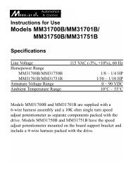
1<br />
Specifications<br />
Max. Continuous HP Range HP Range<br />
AC Armature with 120 with 240<br />
Line Current VAC VAC<br />
Model Voltage (Amps DC) Applied Applied<br />
MMXL02–D240AC 120 OR 240 2 1/20 – 1/4 1/10 – 1/2<br />
MMXL05–D240AC 120 OR 240 5 1/4 – 1/2 1/2 – 1<br />
MMXL10–D240AC† 120 OR 240 10† 1/2 – 1 1 – 2<br />
† Requires Minarik heat sink kit p/n 223–0159 above 5 amps<br />
AC Line Voltage<br />
120/240 VAC ± 10%, 50/60 Hz, single phase<br />
Armature Voltage Range<br />
120 VAC input 0-130 VDC<br />
240 VAC input 0 – 240 VDC<br />
Form Factor (at base speed) 1.05<br />
Acceleration/Deceleration Time Range (no load)<br />
0.5 – 6 seconds<br />
Analog Input Voltage Range* [S1(–) to S2(+)]<br />
0 – 5 VDC<br />
Input Impedance (S1 to S2 with 5 VDC input) approximately 70K ohms<br />
Potentiometer Circuit Isolation (-PCM models only) HCPL 7840:2500 VAC<br />
Inhibit Circuit Isolation (-PCM models only)<br />
HCPL 0453:2500 VAC<br />
Speed Regulation<br />
1% base speed or better<br />
Ambient Temp. Range (chassis drive)<br />
10°C – 40°C††<br />
†† MMXL 10-D240A C is rated for 10 amps DC max @ 25ºC ambient. Derate to 7<br />
amps DC above 25ºC.<br />
* Signal must be isolated on non-PCM drives; -PCM drives can use grounded or<br />
isolated voltage signal.<br />
Vibration<br />
Weight<br />
MMXL02–D240AC<br />
MMXL05–D240AC<br />
MMXL10–D240AC<br />
0.5g max (20 – 50 Hz)<br />
0.1 g max (>50 Hz)<br />
0.66 lb [0.30 kg]<br />
0.72 lb [0.32 kg]<br />
0.82 lb [0.37 kg]
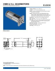
2<br />
Dimensions<br />
3.64 [92]<br />
0.19 [5]<br />
S2<br />
S1<br />
C504<br />
IL502<br />
C501<br />
C505<br />
C502<br />
R501<br />
C503<br />
D<br />
Q503<br />
T501<br />
L1 L2<br />
A1<br />
1.75 [44]<br />
CURRENT<br />
LIMIT<br />
TH501<br />
POWER<br />
IL501<br />
CURRENT LIMIT<br />
L<br />
0.70 [18]<br />
3.80 [97]<br />
4.30 [109]<br />
A<br />
2.10 [53]<br />
0.82 [21]<br />
0.96 [24]<br />
0.19 [5]<br />
DIMENSION “A”<br />
MODEL<br />
HEIGHT<br />
MMXL02 2.50 [62]<br />
MMXL05 3.20 [81]<br />
MMXL10 3.90 [99]<br />
ALL DIMENSIONS IN INCHES<br />
[MILLIMETERS]<br />
Figure 1. MMXL Dimensions
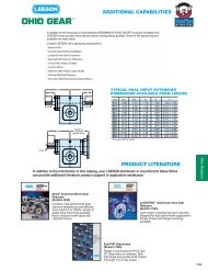
Dimensions<br />
3<br />
6.90 [175]<br />
6.30 [160]<br />
5.90 [150]<br />
S3<br />
C504<br />
C502<br />
R501<br />
4.40 [112]<br />
C501<br />
IL502<br />
3.70 [94]<br />
LIMIT<br />
POWER<br />
TH501<br />
IL501<br />
0.70 [18]<br />
MIN SPD IR COMP DECEL ACCEL<br />
4.00 [102]<br />
1.00 [25]<br />
0.13 [3]<br />
ALL DIMENSIONS IN INCHES [MILLIMETERS]<br />
Figure 2. MMXL10 Drive Dimensions With Heat Sink Installed
4<br />
Installation<br />
Mounting<br />
<br />
Warning<br />
Do not install, rewire, or remove this control with input<br />
power applied. Doing so may cause fire or serious injury.<br />
Make sure you have read and understood the Safety Warnings<br />
before attempting installation.<br />
• Drive components are sensitive to electrostatic fields. Avoid<br />
direct contact with the circuit board. Hold drive by the chassis<br />
only.<br />
• Protect the drive from dirt, moisture, and accidental contact.<br />
• Provide sufficient room for access to the terminal block and<br />
calibration trimpots.<br />
• Mount the drive away from heat sources. Operate the drive<br />
within the specified ambient operating temperature range.<br />
• Prevent loose connections by avoiding excessive vibration of<br />
the drive.<br />
• Mount drive with its board in either a horizontal or vertical<br />
plane. Six 0.19 in. (5 mm) wide slots in the chassis accept #8<br />
pan head screws. Fasten either the large base or the narrow<br />
flange of the chassis to the subplate.
Installation<br />
5<br />
• The chassis must be earth grounded. Use a star washer<br />
beneath the head of at least one of the mounting screws to<br />
penetrate the anodized chassis surface and to reach bare<br />
metal.<br />
Wiring<br />
<br />
<br />
Warning<br />
Do not install, remove, or rewire this equipment with power<br />
applied. Failure to heed this warning may result in fire,<br />
explosion, or serious injury.<br />
Circuit potentials are at 115 or 230 VAC above ground. To<br />
prevent the risk of injury or fatality, avoid direct contact with<br />
the printed circuit board or with circuit elements.<br />
Do not disconnect any of the motor leads from the drive<br />
unless power is removed or the drive is disabled. Opening<br />
any one motor lead may destroy the drive.<br />
• Use 16–20 AWG wire for speed adjust potentiometer wiring.<br />
Use 14–16 AWG wire for AC line (L1, L2) and motor (A1 and<br />
A2) wiring.
6 Installation<br />
Shielding guidelines<br />
<br />
Warning<br />
Under no circumstances should power and logic leads be<br />
bundled together. Induced voltage can cause unpredictable<br />
behavior in any electronic device, including motor controls.<br />
As a general rule, Minarik recommends shielding of all conductors.<br />
If it is not practical to shield power conductors, Minarik<br />
recommends shielding all logic-level leads. If shielding logic leads<br />
is not practical, the user should twist all logic leads with themselves<br />
to minimize induced noise.<br />
It may be necessary to earth ground the shielded cable. If noise is<br />
produced by devices other than the drive, ground the shield at the<br />
drive end. If noise is generated by a device on the drive, ground<br />
the shield at the end away from the drive. Do not ground both ends<br />
of the shield.<br />
If the drive continues to pick up noise after grounding the shield, it<br />
may be necessary to add AC line filtering devices, or to mount the<br />
drive in a less noisy environment.<br />
Logic wires from other input devices, such as motion controllers<br />
and PLL velocity controllers, must be separated from power lines in<br />
the same manner as the logic I/O on this drive.
Installation<br />
7<br />
Heat sinking<br />
Model MMXL10-D240AC requires an additional heat sink (Minarik<br />
part number 223–0159) when the continuous armature current is<br />
above 5 ADC. All other chassis drives have sufficient heat sinking<br />
in their basic configurations.<br />
Apply a thermally conductive heat sink compound (such as Dow<br />
Corning® 340 Heat Sink Compound) between the drive chassis<br />
and heat sink surface for optimum heat transfer.<br />
Line fusing<br />
Protect all Minarik drives with AC line fuses. Use fast acting AC line<br />
fuses rated for 250 volts, and approximately 150% – 200% of the<br />
maximum armature current. Fuse only the “hot” side of the AC line<br />
(L1) if using 115 VAC line voltage. Do not add line fuses to L1 and<br />
L2 unless you use 240 VAC line voltage. See Table 1 on page 8<br />
for recommended line fuse sizes:
8 Installation<br />
Table 1. Recommended Line Fuse Sizes<br />
Maximum Armature<br />
AC Line Fuse<br />
Current (DC Amps) Rating (AC Amps)<br />
1.5 and below 3<br />
2.6 5<br />
3.5 8<br />
5.0 10<br />
7.6 15<br />
10 15<br />
Minarik Corporation offers two fuse kits: part number 050–0069<br />
(3–8A Fuse Kit) and 050–0073 (5–20A Fuse Kit). Refer to<br />
Replacement Parts (page 47) for fuse kit contents.
Installation<br />
9<br />
Speed adjust potentiometer<br />
<br />
Warning<br />
Be sure that the potentiometer tabs do not make contact with<br />
the potentiometer enclosure. Grounding the input will cause<br />
damage to the drive.<br />
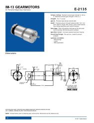
Mount the speed adjust potentiometer through a 0.38 in. (10 mm)<br />
hole with the hardware provided (Figure 3). Install the circular<br />
insulating disk between the panel and the 10K ohm speed adjust<br />
potentiometer. Twist the speed adjust potentiometer wire to avoid<br />
picking up unwanted electrical noise. If speed adjust potentiometer<br />
wires are longer than 18 in. (457 mm), use shielded cable. Keep<br />
speed adjust potentiometer wires separate from power leads (L1,<br />
L2, A1, A2).<br />
MOUNT THROUGH A 0.38 IN. (10 MM) HOLE<br />
CW<br />
WIPER<br />
W<br />
NUT<br />
STAR<br />
WASHER<br />
SPEED ADJUST<br />
POTENTIOMETER<br />
PANEL<br />
INSULATING DISK<br />
Figure 3. Speed Adjust Potentiometer
10 Installation<br />
Isolation<br />
NOTE: Isolation is incorporated in MMXL-PCM drives only.<br />
The reference circuit (S1, S2 and S3) is optically isolated from the<br />
rest of the drive electronics via HCPL7840. It will accept either a<br />
grounded or isolated signal reference.<br />
The inhibit input is also optically isolated from the rest of the drive<br />
electronics via HCPL0453. It will accept a grounded or isolated bittype<br />
open collector (or switch) input.
Installation<br />
11<br />
Connections<br />
<br />
Warning<br />
Do not connect this equipment with power applied.<br />
Failure to heed this directive may result in fire or serious injury.<br />
Minarik strongly recommends the installation of a master<br />
power switch in the voltage input line, as shown in<br />
Figure 4 (page 13). The switch contacts should be rated at a<br />
minimum of 200% of motor nameplate current and 250 volts.<br />
Power, fuse and motor connections<br />
Connect the power input leads, an external line fuse and a DC<br />
motor to the drive’s printed circuit board (PCB) as shown in Figure<br />
4, page 13.<br />
Master power switch<br />
Decelerating to minimum speed, regenerative braking, or coasting<br />
to a stop may not stop a drive that is malfunctioning. Removing AC<br />
line power (both L1 and L2) is the only acceptable method for<br />
emergency stopping. For this reason, Minarik strongly<br />
recommends installing an emergency stop switch on both the L1<br />
and L2 inputs. The switch contacts must be rated at a minimum of<br />
250 volts and 200% of maximum drive current.
12 Installation<br />
Motor<br />
Minarik drives supply motor voltage from A1 and A2 terminals. It is<br />
assumed throughout this manual that, when A1 is positive with<br />
respect to A2 , the motor will rotate clockwise (CW) while looking at<br />
the output shaft protruding from the front of the motor. If this is<br />
opposite of the desired rotation, simply reverse the wiring of A1<br />
and A2 with each other.<br />
Connect a DC motor to PCB terminals A1 and A2 as shown in<br />
Figure 4. Ensure that the motor voltage rating is consistent with the<br />
drive’s output voltage.<br />
Power input<br />
Connect the AC line power leads to PCB terminals L1 and L2, or to<br />
a double-throw, single-pole master power switch (recommended).<br />
Line fuse<br />
Wire an external line fuse between the stop switch (if installed) and<br />
the L1 terminal the circuit board. An additional line fuse should be<br />
installed on L2 if the input voltage is 230VAC. The line fuse(s)<br />
should be rated at 250 volts and 150 - 200% of maximum motor<br />
nameplate current. Refer to the line fuse chart on page 8 for fuse<br />
ratings.
CW<br />
S3<br />
S2<br />
S1<br />
C504<br />
C505<br />
C502<br />
R501<br />
C503<br />
A1<br />
A2<br />
+<br />
MOTOR<br />
10K OHM<br />
SPEED ADJUST<br />
POTENTIOMETER<br />
INHIBIT<br />
IL502<br />
C501<br />
D<br />
T501<br />
L2<br />
L1<br />
* NOTE:<br />
FUSE L2<br />
ONLY IF LINE<br />
VOLTAGE IS<br />
240 VAC.<br />
CURRENT<br />
LIMIT<br />
CURRENT LIMIT<br />
POWER<br />
TH501<br />
IL501<br />
*<br />
FUSE<br />
MIN SPD<br />
IR COMP<br />
DECEL<br />
ACCEL<br />
STOP<br />
SWITCH<br />
120/240 VAC<br />
LINE VOLTAGE<br />
Installation<br />
Figure 4. MMXL Series Connections<br />
13
14 Installation<br />
Voltage follower<br />
Instead of using a speed adjust potentiometer, the drive may be<br />
wired to follow a 0 – 5 VDC grounded* or isolated voltage signal<br />
(Figure 5). Connect the signal return (–) to S1. Connect the signal<br />
high or (+) to S2. Make no connection to S3. A potentiometer can<br />
be used to scale the analog input voltage.<br />
* Refers to MMXL -PCM models only.<br />
0 - 5 VDC<br />
VOLTAGE SIGNAL<br />
REF (+)<br />
COM (-)<br />
S2<br />
S1<br />
C504<br />
C505<br />
C502<br />
R501<br />
C<br />
INHIBIT<br />
IL502<br />
CURRENT<br />
LIMIT<br />
CURRENT LIMIT<br />
C501<br />
POWER<br />
TH50<br />
IL50<br />
MAX SPD MIN SPD<br />
IR COMP<br />
DECEL<br />
ACCEL<br />
Figure 5. Voltage Follower Connections
15<br />
Operation<br />
<br />
<br />
Warning<br />
Dangerous voltages exist on the drive when it is powered,<br />
and up to 30 seconds after power is removed and the motor<br />
stops. BE ALERT. High voltages can cause serious or fatal<br />
injury. For your safety, use personal protective equipment<br />
(PPE) when operating this drive.<br />
If the motor or drive does not perform as described,<br />
disconnect the AC line voltage immediately. Refer to the<br />
Troubleshooting section on page 39 for further assistance.<br />
Before applying power<br />
• Verify that no conductive material is present on the printed<br />
circuit board.<br />
• Ensure that all jumpers are properly set.
16 Operation<br />
Startup<br />
To start the drive:<br />
1. Turn the speed adjust potentiometer full counterclockwise<br />
(CCW). If the drive is following a voltage signal, set the<br />
voltage signal to 0 VDC.<br />
2. Apply AC line voltage.<br />
3. Slowly advance the speed adjust potentiometer clockwise<br />
(CW). If the drive is following a voltage signal, slowly increase<br />
the voltage signal. The motor slowly accelerates as the<br />
potentiometer is turned CW, or the voltage signal is increased.<br />
Continue until the desired speed is reached.<br />
4. Remove AC line voltage from the drive to coast the motor to a<br />
stop.
Operation<br />
17<br />
Starting and Stopping Methods<br />
<br />
Warning<br />
Decelerating to minimum speed, regenerative braking, or<br />
coasting to a stop is recommended for frequent starts and<br />
stops. Do not use any of these methods for emergency<br />
stopping. They may not stop a drive that is malfunctioning.<br />
Removing AC line power (both L1 and L2) is the only<br />
acceptable method for emergency stopping.<br />
For this reason, Minarik strongly recommends installing<br />
an emergency stop switch on both the L1 and L2 inputs<br />
(see Connections on page 13).<br />
Frequent decelerating to minimum speed or regenerative<br />
braking produces high torque. This may cause damage to<br />
motors, especially gearmotors that are not properly sized for<br />
the application.<br />
Line starting and line stopping<br />
Line starting and line stopping (applying and removing AC<br />
line voltage) is recommended for infrequent starting and stopping<br />
of a drive only. When AC line voltage is applied to the drive,<br />
the motor accelerates to the speed set by the speed adjust<br />
potentiometer. When AC line voltage is removed, the motor coasts<br />
to a stop.
18 Operation<br />
Automatic restart upon power restoration<br />
All drives automatically run to set speed when power is applied and<br />
the drive is enabled. The drive will accelerate at a rate controlled<br />
by the ACCEL trimpot. Refer to the Calibration section for<br />
information on adjusting this setting.<br />
Inhibit terminals<br />
<br />
Warning<br />
Inhibit is used for frequent starts and stops. It must never<br />
be used as an emergency stop because it may not stop a<br />
drive that is malfunctioning. Removing AC power (L1 and<br />
L2) is the only acceptable method for emergency stopping.<br />
Jumper the inhibit terminals to coast the motor to a stop<br />
(Figure 6). Remove the jumper to accelerate the motor to set<br />
speed.<br />
The inhibit terminals on MMXL-PCM model drives are optically<br />
isolated from the drive electronics. The user may apply a simple<br />
switch closure or an open-collector input, which may be isolated or<br />
non-isolated.
Operation<br />
19<br />
Inhibit plug<br />
Minarik Corporation offers two accessory plug harnesses for use<br />
with the inhibit terminals:<br />
Table 2. Inhibit Plug Part Numbers<br />
Minarik®<br />
Part Number Description<br />
201-0024 Inhibit plug with 18-in. (46 cm) wires<br />
201-0079 Inhibit plug with 36-in. (91 cm) wires<br />
Twist inhibit plug wires and separate them from other powercarrying<br />
wires or sources of electrical noise. Use shielded cable if<br />
the inhibit plug wires are longer than 18 inches (46 cm). If shielded<br />
cable is used, ground only one end of the shield to earth ground.<br />
Do not ground both ends of the shield.<br />
INHIBIT<br />
TERMINAL<br />
C504<br />
C505<br />
C502<br />
R501<br />
C503<br />
S2<br />
S1<br />
INHIBIT<br />
IL502<br />
C501<br />
D<br />
Q503<br />
T501<br />
CURRENT<br />
Figure 6. Inhibit Terminal Location
20 Operation<br />
Decelerating to minimum speed<br />
A switch may be used to decelerate the motor to minimum speed.<br />
Connect the switch as shown in Figure 7. Close the switch<br />
between S1 and S2 to decelerate the motor from set speed. Open<br />
the switch to accelerate the motor to set speed. The ACCEL and<br />
DECEL trimpot settings determine the rate at which the motor<br />
accelerates and decelerates, respectively.<br />
S3<br />
CW<br />
S2<br />
10K OHM<br />
SPEED ADJUST<br />
POTENTIOMETER<br />
S1<br />
RUN<br />
DECEL TO<br />
MIN SPEED<br />
Figure 7. Run/Decelerate to Minimum Speed Switch
Operation<br />
21<br />
Dynamic braking<br />
<br />
Warning<br />
Wait for the motor to come to a complete stop before setting<br />
the RUN/BRAKE switch to RUN. This will prevent high<br />
armature currents from damaging the motor or drive.<br />
Dynamic braking may be used to rapidly stop a motor (see<br />
Figure 8 on page 22). For the RUN/BRAKE switch, use a doublepole,<br />
double throw switch rated for at least the maximum DC<br />
armature voltage and maximum braking current.<br />
RUN/BRAKE switch<br />
Install a double-pole, double-throw switch between the INHIBIT<br />
terminals and a dynamic brake resistor as shown in Figure 8 on<br />
page 22. Set the switch to the BRAKE position to dynamically brake<br />
the motor to a stop. Set the switch to the RUN position to accelerate<br />
the motor to set speed at a rate controlled by the ACCEL trimpot.<br />
Dynamic brake resistor sizes<br />
Size the dynamic brake resistor according to the motor current<br />
rating (refer to Table 3 on page 22). The dynamic brake resistance<br />
listed in the table is the smallest recommended resistance allowed<br />
to prevent possible demagnetization of the motor. The motor stops<br />
less rapidly with higher brake resistor values.
22 Operation<br />
Table 3. Dynamic Brake Resistor Part Numbers<br />
Minimum Minimum<br />
Motor Armature Dynamic Brake Dynamic Brake<br />
Current Rating Resistor Value Resistor Wattage<br />
Less than 2 ADC 1 ohm 1W<br />
2–3 ADC 5 ohm 5W<br />
3–5 ADC 10 ohm 10W<br />
5–10 ADC 20 ohm 20W<br />
10–17 ADC 40 ohm 50W<br />
For motors rated 1/17 horsepower and lower, a brake resistor is not<br />
necessary since the armature resistance is high enough to stop the<br />
motor without demagnetization. Replace the dynamic brake with 12<br />
gauge wire.<br />
A1<br />
A2<br />
RUN<br />
BRAKE<br />
DYNAMIC BRAKE<br />
RESISTOR<br />
MOTOR<br />
INHIBIT<br />
Figure 8. Dynamic Brake Connection
23<br />
Calibration<br />
Each drive is factory calibrated to its maximum current rating.<br />
Readjust the calibration trimpot settings to accommodate lower<br />
current motors.<br />
All adjustments increase with CW rotation, and decrease with CCW<br />
rotation. Use a non-metallic screwdriver for calibration. Each<br />
trimpot is identified on the printed circuit board.<br />
C502<br />
R501<br />
A1<br />
S2<br />
S1<br />
A2<br />
INHIBIT<br />
IL502<br />
C501<br />
D<br />
Q503<br />
T501<br />
L2<br />
L1<br />
CURRENT<br />
LIMIT<br />
TH501<br />
POWER<br />
IL501<br />
CURRENT<br />
LIMIT<br />
CURRENT LIMIT<br />
MAX SPD MIN SPD IR COMP DECEL<br />
ACCEL<br />
MAX<br />
SPEED<br />
MIN<br />
SPEED<br />
IR COMP<br />
DECELERATION<br />
ACCELERATION<br />
Figure 9. Calibration Trimpot Layout
24 Calibration<br />
Calibration procedure<br />
Before applying power<br />
1. Verify that no conductive material is present on the printed<br />
circuit board.<br />
2. Set all trimpots full except CURRENT LIMIT full<br />
counterclockwise (CCW).<br />
3. Set the CURRENT LIMIT trimpot full clockwise (CW).<br />
4. Set the speed adjust potentiometer or input signal to zero<br />
speed.<br />
5. Set the INHIBIT switch to INHIBIT, or install the jumper<br />
between the INHIBIT terminals of SO501.<br />
6. Apply line voltage to the drive. The green POWER LED shall<br />
light, but the motor should remain stopped.<br />
7. Set the INHIBIT switch to ENABLE, or remove the jumper<br />
between the INHIBIT terminals of SO501.
Calibration<br />
25<br />
MINIMUM SPEED (MIN SPD)<br />
MIN SPD determines the minimum speed when the speed<br />
adjust potentiometer is turned full CCW. It is factory set to<br />
zero speed. To calibrate MIN SPD:<br />
1. Set the speed adjust potentiometer full CCW.<br />
2. Adjust the MIN SPD trimpot until the motor turns at the<br />
desired minimum speed.<br />
MAXIMUM SPEED (MAX SPD)<br />
The MAX SPD setting determines the maximum motor<br />
speed when the speed adjust potentiometer is turned full<br />
CW. It is factory set for maximum rated motor speed. To<br />
calibrate MAX SPD:<br />
1. Set the MAX trimpot full CCW.<br />
2. Turn the speed adjust potentiometer full CW.<br />
3. Adjust the MAX SPD trimpot until the desired<br />
maximum motor speed is reached.
26 Calibration<br />
ACCELERATION (ACCEL)<br />
The ACCELERATE setting determines the time the motor takes to<br />
ramp to a higher speed. See Specifications on page 1 for<br />
approximate acceleration times. The ACCELERATE setting is<br />
factory set to its minimum value (full CCW).<br />
Turn the ACCEL trimpot CW to increase the acceleration time and<br />
CCW to decrease the acceleration time.<br />
DECELERATION (DECEL)<br />
The DECELERATE setting determines the time the motor takes to<br />
ramp to a lower speed. See Specifications on page 1 for<br />
approximate deceleration times. The DECELERATE setting is<br />
factory set to its minimum value (full CCW).<br />
Turn the DECEL trimpot CW to increase the deceleration time and<br />
CCW to decrease the deceleration time.
Calibration<br />
27<br />
REGULATION (IR COMP)<br />
The IR COMP setting determines the degree to which motor speed<br />
is held constant as the motor load changes. It is factory set for<br />
optimum motor regulation. Recalibrate the IR COMP setting when<br />
using a lower current rated motor. Refer to Figures 10 - 13 (pp 29 -<br />
32) for typical IR COMP settings, or recalibrate using the following<br />
procedure:<br />
If the motor does not maintain set speed as the load changes,<br />
gradually rotate the IR COMP trimpot CW. If the motor oscillates<br />
(overcompensation), the IR COMP trimpot may be set too high<br />
(CW). Turn the IR COMP trimpot CCW to stabilize the drive.
28 Calibration<br />
CURRENT LIMIT (CURR LIM)<br />
<br />
Warning<br />
Although the current limit trimpot can be set to exceed the<br />
motor's maximum armature current rating, Minarik<br />
recommends you do not run the motor continuously beyond<br />
that rating. Continuous operation beyond the maximum<br />
armature current rating may cause thermal degradation of the<br />
motor and drive.<br />
The CURRENT LIMIT setting determines the maximum torque for<br />
accelerating and driving the motor. CURRENT LIMIT is factory set<br />
at 120% of maximum drive current. You must recalibrate the<br />
CURRENT LIMIT setting if using a lower current rated motor.<br />
Refer to Figures 10 - 13 (pp 29 - 32) for typical CURRENT LIMIT<br />
settings.<br />
1. With no power applied to the drive, connect a DC ammeter in<br />
series with the motor armature.<br />
2. Set the CURRENT LIMIT trimpot to full CCW.<br />
3. Carefully lock the motor armature. Ensure that the motor is<br />
firmly mounted.<br />
4. Apply line power. The motor should be stopped.<br />
5. Set the speed potentiometer or reference signal to maximum<br />
speed. The motor should remain stopped.
Calibration<br />
29<br />
CURRENT LIMIT (cont.)<br />
6. Slowly rotate the CURRENT LIMIT trimpot clockwise (CW)<br />
until the ammeter reads 120% of maximum motor armature<br />
current.<br />
7. Set the speed adjust potentiometer or reference signal to zero<br />
speed.<br />
8. Remove power from the drive.<br />
9. Remove the lock from the motor shaft.<br />
10. Remove the ammeter in series with the motor armature.
30 Calibration<br />
MMXL02-D240AC<br />
MOTOR<br />
HP: 1/20<br />
VOLTS 90 VDC<br />
RPM: 1750<br />
AMPS: 0.5 ADC<br />
MOTOR<br />
HP: 1/8<br />
VOLTS 90 VDC<br />
RPM: 1750<br />
AMPS: 1.3 ADC<br />
MOTOR<br />
HP: 1/4<br />
VOLTS 90 VDC<br />
RPM: 1750<br />
AMPS: 2.5 ADC<br />
CURR<br />
LIM<br />
CURR<br />
LIM<br />
CURR<br />
LIM<br />
I/R<br />
COMP<br />
I/R<br />
COMP<br />
I/R<br />
COMP<br />
MOTOR<br />
HP: 1/2<br />
VOLTS 90 VDC<br />
RPM: 1750<br />
AMPS: 5.0 ADC<br />
MOTOR<br />
HP: 1/3<br />
VOLTS 90 VDC<br />
RPM: 1750<br />
AMPS: 3.5 ADC<br />
MOTOR<br />
HP: 1/4<br />
VOLTS 90 VDC<br />
RPM: 1750<br />
AMPS: 2.7 ADC<br />
MMXL05-D240AC<br />
CURR<br />
LIM<br />
CURR<br />
LIM<br />
CURR<br />
LIM<br />
I/R<br />
COMP<br />
I/R<br />
COMP<br />
I/R<br />
COMP<br />
MMXL10-D240AC<br />
MOTOR<br />
HP: 1/20<br />
VOLTS 90 VDC<br />
RPM: 1750<br />
AMPS: 5.0 ADC<br />
MOTOR<br />
HP: 3/4<br />
VOLTS 90 VDC<br />
RPM: 1750<br />
AMPS: 7.6 ADC<br />
MOTOR<br />
HP: 1<br />
VOLTS 90 VDC<br />
RPM: 1750<br />
AMPS: 10.0 ADC<br />
CURR<br />
LIM<br />
CURR<br />
LIM<br />
CURR<br />
LIM<br />
I/R<br />
COMP<br />
I/R<br />
COMP<br />
I/R<br />
COMP<br />
Figure 10. Approximate CURRENT LIMIT and IR COMP Settings<br />
for 120 VAC in, 90 VDC out (actual settings may vary)
Calibration<br />
31<br />
MMXL02-D240AC<br />
MOTOR<br />
HP: 1/20<br />
VOLTS: 130 VDC<br />
RPM: 2500<br />
AMPS: 0.4 ADC<br />
MOTOR<br />
HP: 1/8<br />
VOLTS: 130 VDC<br />
RPM: 2500<br />
AMPS: 1.0 ADC<br />
MOTOR<br />
HP: 1/4<br />
VOLTS: 130 VDC<br />
RPM: 2500<br />
AMPS: 1.8 ADC<br />
CURR<br />
LIM<br />
CURR<br />
LIM<br />
CURR<br />
LIM<br />
I/R<br />
COMP<br />
I/R<br />
COMP<br />
I/R<br />
COMP<br />
MOTOR<br />
HP: 1/2<br />
VOLTS: 130 VDC<br />
RPM: 2500<br />
AMPS: 3.8 ADC<br />
MOTOR<br />
HP: 1/3<br />
VOLTS: 130 VDC<br />
RPM: 2500<br />
AMPS: 2.6 ADC<br />
MOTOR<br />
HP: 1/4<br />
VOLTS: 130 VDC<br />
RPM: 2500<br />
AMPS: 2.0 ADC<br />
MMXL05-D240AC<br />
CURR<br />
LIM<br />
CURR<br />
LIM<br />
CURR<br />
LIM<br />
I/R<br />
COMP<br />
I/R<br />
COMP<br />
I/R<br />
COMP<br />
MMXL10-D240AC<br />
MOTOR<br />
HP: 1/2<br />
VOLTS: 130 VDC<br />
RPM: 2500<br />
AMPS: 3.8 ADC<br />
MOTOR<br />
HP: 3/4<br />
VOLTS: 130 VDC<br />
RPM: 1750<br />
AMPS: 5.7 ADC<br />
MOTOR<br />
HP: 1<br />
VOLTS: 130 VDC<br />
RPM: 1750<br />
AMPS: 7.5 ADC<br />
CURR<br />
LIM<br />
CURR<br />
LIM<br />
CURR<br />
LIM<br />
I/R<br />
COMP<br />
I/R<br />
COMP<br />
I/R<br />
COMP<br />
Figure 11. Approximate CURRENT LIMIT and IR COMP Settings<br />
for 120 VAC in, 130 VDC out (actual settings may vary)
32 Calibration<br />
MMXL02-D240AC<br />
MOTOR<br />
HP: 1/2<br />
VOLTS: 180 VDC<br />
RPM: 1750<br />
AMPS: 1.4 ADC<br />
MOTOR<br />
HP: 1/4<br />
VOLTS: 180 VDC<br />
RPM: 1750<br />
AMPS: 1.0 ADC<br />
MOTOR<br />
HP: 1/8<br />
VOLTS: 180 VDC<br />
RPM: 1750<br />
AMPS: 0.6 ADC<br />
CURR<br />
LIM<br />
CURR<br />
LIM<br />
CURR<br />
LIM<br />
I/R<br />
COMP<br />
I/R<br />
COMP<br />
I/R<br />
COMP<br />
MOTOR<br />
HP: 1<br />
VOLTS: 180 VDC<br />
RPM: 1750<br />
AMPS: 5.0 ADC<br />
MOTOR<br />
HP: 3/4<br />
VOLTS: 180 VDC<br />
RPM: 1750<br />
AMPS: 3.5 ADC<br />
MOTOR<br />
HP: 1/2<br />
VOLTS: 180 VDC<br />
RPM: 1750<br />
AMPS: 2.7 ADC<br />
MMXL05-D240AC<br />
CURR<br />
LIM<br />
CURR<br />
LIM<br />
CURR<br />
LIM<br />
I/R<br />
COMP<br />
I/R<br />
COMP<br />
I/R<br />
COMP<br />
MMXL10-D240AC<br />
MOTOR<br />
HP: 1<br />
VOLTS: 180 VDC<br />
RPM: 1750<br />
AMPS: 5.0 ADC<br />
MOTOR<br />
HP: 1 1/2<br />
VOLTS: 180 VDC<br />
RPM: 1750<br />
AMPS: 7.6 ADC<br />
MOTOR<br />
HP: 2<br />
VOLTS: 180 VDC<br />
RPM: 1750<br />
AMPS: 10.0 ADC<br />
CURR<br />
LIM<br />
CURR<br />
LIM<br />
CURR<br />
LIM<br />
I/R<br />
COMP<br />
I/R<br />
COMP<br />
I/R<br />
COMP<br />
Figure 12. Approximate CURRENT LIMIT and IR COMP Settings<br />
for 240 VAC in, 180 VDC out (actual settings may vary)
Calibration<br />
33<br />
MMXL02-D240AC<br />
MOTOR<br />
HP: 1/2<br />
VOLTS: 240 VDC<br />
RPM: 2500<br />
AMPS: 1.9 ADC<br />
MOTOR<br />
HP: 1/3<br />
VOLTS: 240 VDC<br />
RPM: 2500<br />
AMPS: 1.0 ADC<br />
MOTOR<br />
HP: 1/4<br />
VOLTS: 240 VDC<br />
RPM: 2500<br />
AMPS: 0.75 ADC<br />
CURR<br />
LIM<br />
CURR<br />
LIM<br />
CURR<br />
LIM<br />
I/R<br />
COMP<br />
I/R<br />
COMP<br />
I/R<br />
COMP<br />
MOTOR<br />
HP: 1<br />
VOLTS: 180 VDC<br />
RPM: 1750<br />
AMPS: 5.0 ADC<br />
MOTOR<br />
HP: 3/4<br />
VOLTS: 240 VDC<br />
RPM: 2500<br />
AMPS: 2.7 ADC<br />
MOTOR<br />
HP: 1/2<br />
VOLTS: 240 VDC<br />
RPM: 2500<br />
AMPS: 2.0 ADC<br />
MMXL05-D240AC<br />
CURR<br />
LIM<br />
CURR<br />
LIM<br />
CURR<br />
LIM<br />
I/R<br />
COMP<br />
I/R<br />
COMP<br />
I/R<br />
COMP<br />
MMXL10-D240AC<br />
MOTOR<br />
HP: 1<br />
VOLTS: 240 VDC<br />
RPM: 2500<br />
AMPS: 3.8 ADC<br />
MOTOR<br />
HP: 1 1/2<br />
VOLTS: 240 VDC<br />
RPM: 2500<br />
AMPS: 5.7 ADC<br />
MOTOR<br />
HP: 2<br />
VOLTS: 240 VDC<br />
RPM: 2500<br />
AMPS: 7.5 ADC<br />
CURR<br />
LIM<br />
CURR<br />
LIM<br />
CURR<br />
LIM<br />
I/R<br />
COMP<br />
I/R<br />
COMP<br />
I/R<br />
COMP<br />
Figure 13. Approximate CURRENT LIMIT and IR COMP Settings<br />
for 240 VAC in, 240 VDC out (actual settings may vary)
34<br />
Application Notes<br />
Multiple fixed speeds<br />
Replace the speed adjust potentiometer with series resistors<br />
having a total series resistance of 10 K ohms (Figure 14). Add a<br />
single pole, multi-position switch with the correct number of<br />
positions for the desired number of fixed speeds.<br />
R1<br />
S3<br />
S2<br />
S1<br />
R2<br />
R3<br />
TOTAL SERIES<br />
RESISTANCE<br />
10K OHMS<br />
R4<br />
Figure 14. Multiple Fixed Speeds
Application Notes<br />
35<br />
Adjustable speeds using potentiometers in<br />
series<br />
Connect two speed adjust potentiometers as shown in<br />
Figure 15 to select between independent forward and reverse<br />
speeds.<br />
CW<br />
S3<br />
S2<br />
S1<br />
HIGH<br />
SPEED<br />
LOW<br />
SPEED<br />
5K<br />
OHM<br />
CW<br />
5K<br />
OHM<br />
Figure 15. Adjustable Speeds Using Potentiometers In Series
36 Application Notes<br />
Independent adjustable speeds<br />
Connect two speed adjust potentiometers with a single-pole, multiposition<br />
switch and two or more potentiometers in parallel, with a<br />
total resistance of 10K ohms. Figure 16 shows the connection of<br />
two independent speed adjust potentiometers that can be mounted<br />
at two separate operating stations.<br />
S3<br />
SPEED 2<br />
CW<br />
CW<br />
S2<br />
S1<br />
SPEED 1<br />
20K<br />
OHM<br />
20K<br />
OHM<br />
Figure 16. Independent Adjustable Speeds
Application Notes<br />
37<br />
RUN/JOG switch<br />
Using a RUN/JOG switch is recommended in applications where<br />
quick stopping is not needed and frequent jogging is required. Use<br />
a single pole, two position switch for the RUN/JOG switch, and a<br />
single-pole, normally-closed, momentary operated pushbutton for<br />
the JOG pushbutton.<br />
RUN/JOG option #1<br />
In option #1 (Figure 17), connect the RUN/JOG switch and the<br />
JOG pushbutton to the INHIBIT terminals. When the RUN/JOG<br />
switch is set to JOG, the motor coasts to minimum speed. Press<br />
the JOG pushbutton to jog the motor. Return the RUN/JOG switch<br />
to RUN for normal operation.<br />
RUN<br />
JOG<br />
PUSHBUTTON<br />
INHIBIT<br />
JOG<br />
Figure 17. RUN/JOG Option #1
38 Application Notes<br />
RUN/JOG option #2<br />
In option #2, connect the RUN/JOG switch to the speed adjust<br />
potentiometer using a single-pole, two-position switch for the<br />
RUN/JOG switch, and a single-pole, normally-closed, momentary<br />
operated pushbutton for the JOG pushbutton as shown in Figure<br />
18. When the RUN/JOG switch is set to JOG, the motor<br />
decelerates to minimum speed. Press the JOG pushbutton to jog<br />
the motor. Return the RUN/JOG switch to RUN for normal<br />
operation.<br />
S3<br />
CW<br />
S2<br />
S1<br />
10K OHM<br />
SPEED ADJUST<br />
POTENTIOMETER<br />
RUN<br />
JOG<br />
JOG<br />
PUSHBUTTON<br />
Figure 18. RUN/JOG Option #2
Application Notes<br />
39<br />
Leader-follower application<br />
In this application, use a PCM4 to monitor the speed of the leader<br />
motor (Figure 19). The PCM4 outputs a voltage proportional to the<br />
leader motor armature voltage. The follower drive uses this voltage<br />
reference to set the speed of the follower motor. An optional ratio<br />
potentiometer may be used to scale the PCM4 output voltage.<br />
Leader<br />
Drive<br />
A1<br />
A2<br />
MOTOR<br />
9 (+)<br />
8<br />
7 (-)<br />
TB501<br />
(+) 2<br />
PCM4 (-) 1<br />
TB502<br />
10K Ohm<br />
(optional)<br />
S2<br />
S1<br />
Follower<br />
Drive<br />
Figure 19. Leader-Follower Application
40 Application Notes<br />
Single speed potentiometer control of<br />
multiple drives (-PCM models only)<br />
Because the potentiometer circuit is optically isolated from the drive<br />
circuitry, the inputs may be tied together. Up to eight (8) drives can<br />
be controlled with a single speed adjust potentiometer (see Figure<br />
20 below).<br />
S1<br />
A1<br />
S2<br />
DRIVE A<br />
MOTOR<br />
A<br />
S3<br />
A2<br />
S1<br />
A1<br />
S2<br />
DRIVE B<br />
MOTOR<br />
B<br />
S3<br />
A2<br />
Figure 20. Single Speed Potentiometer Control of Multiple<br />
MMXL-PCM Series Drives
Application Notes<br />
41<br />
Reversing<br />
A dynamic brake may be used when reversing the motor direction<br />
(Figure 21). Use a three-pole, three-position switch rated for at<br />
least the maximum DC armature voltage and maximum braking<br />
current. Wait for the motor to stop completely before switching it to<br />
either the forward or reverse direction. See the Dynamic braking<br />
section on page 21 for sizing the dynamic brake resistor.<br />
A1<br />
A2<br />
DYNAMIC<br />
BRAKE<br />
RESISTOR<br />
MOTOR<br />
FWD<br />
BRAKE<br />
REV<br />
INHIBIT<br />
Figure 21. Reversing
42 Application Notes<br />
Reversing with a DIGI-LOK controller<br />
A DIGI-LOK controller, model DLC600, can be used in a reversing<br />
application (Figure 22). The controller must be inhibited while<br />
braking. Without the inhibit feature, the controller will continue to<br />
regulate, causing overshoot when the DIGI-LOK is switched back<br />
to the drive.<br />
MINARIK<br />
DRIVE<br />
S3<br />
S2<br />
S1<br />
A1<br />
A2<br />
Dynamic<br />
Brake<br />
Resistor<br />
S1<br />
S2<br />
FWD<br />
BRAKE<br />
REV<br />
DLC600<br />
Inhibit<br />
Leads<br />
Motor<br />
C<br />
IN<br />
+<br />
Common<br />
Optical<br />
Encoder<br />
Signal<br />
+5 VDC<br />
Magnetic<br />
Pickup<br />
Figure 22. Reversing with a DLC600
43<br />
Troubleshooting<br />
<br />
Warning<br />
Dangerous voltages exist on the drive when it is powered,<br />
and up to 30 seconds after power is removed. When possible,<br />
disconnect the drive while troubleshooting. High voltages can<br />
cause serious or fatal injury.<br />
Before troubleshooting<br />
Perform the following steps before starting any procedure in this<br />
section:<br />
• Disconnect AC line voltage from the drive.<br />
• Check the drive closely for damaged components.<br />
• Check that no conductive or other foreign material has<br />
become lodged on the printed circuit board.<br />
• Verify that every connection is correct and in good condition.<br />
• Verify that there are no short circuits or grounded connections.<br />
• Check that the voltage selection switch settings match the AC<br />
line and output voltages.<br />
• Check that the drive's rated armature and field outputs are<br />
consistent with the motor ratings.<br />
For additional assistance, contact your local Minarik distributor, or<br />
the factory direct: Phone: 1-800-MINARIK (646-2745) or<br />
Fax: 1-800-394-6334
44 Troubleshooting<br />
Diagnostic LEDs<br />
MMXL series drives are equipped with the following diagnostic<br />
LEDs to aid in troubleshooting or monitoring equipment status.<br />
Refer to Figure 23 below.<br />
POWER<br />
Green LED lights when AC line voltage is applied to the drive.<br />
CURRENT LIMIT (CL/FLT)<br />
Red LED lights when drive output current exceeds the threshold<br />
set by the CURRENT LIMIT trimpot.<br />
INHIBIT<br />
S2<br />
S1<br />
IL502<br />
C501<br />
D<br />
Q503<br />
T501<br />
L1 L2 A2<br />
CURRENT<br />
LIMIT<br />
TH501<br />
POWER<br />
IL501<br />
CURRENT LIMIT<br />
MAX SPD MIN SPD<br />
IR COMP<br />
DECEL<br />
ACCEL<br />
CURRENT<br />
LIMIT LED<br />
POWER<br />
LED<br />
Figure 23. Diagnostic LED locations
Symptom<br />
Possible<br />
Causes<br />
Troubleshooting<br />
Suggested<br />
Solutions<br />
45<br />
Line fuse blows<br />
1. Line fuses are the<br />
wrong size.<br />
2. Motor cable or armature<br />
is shorted to ground.<br />
3. Nuisance tripping<br />
caused by a<br />
combination of ambient<br />
conditions and highcurrent<br />
spikes.<br />
1. Check that line fuses are<br />
the proper size.<br />
2. Check motor cable and<br />
armature for shorts.<br />
3. Add a blower to cool the<br />
drive components;<br />
decrease CURRENT<br />
LIMIT settings, or resize<br />
motor and drive for actual<br />
load demand, or check for<br />
incorrectly aligned<br />
mechanical components<br />
or “jams”. See page 27<br />
for information on<br />
adjusting the CURRENT<br />
LIMIT trimpot.<br />
Line fuse does not<br />
blow, but the motor<br />
does not run<br />
1. Reference signal or<br />
speed adjust pot is set<br />
to zero speed.<br />
2. Reference signal or<br />
speed adjust<br />
potentiometer<br />
connections are open.<br />
1. Increase reference signal<br />
or speed adjust<br />
potentiometer setting.<br />
2. Check that the reference<br />
signal or speed adjust<br />
potentiometer connections<br />
are not open.
46 Troubleshooting<br />
Symptom<br />
Possible<br />
Causes<br />
Suggested<br />
Solutions<br />
Line fuse does not<br />
blow, but the motor<br />
does not run (cont.)<br />
3. Drive is overloaded.<br />
4. Drive is not receiving<br />
AC line voltage.<br />
5. Motor is not connected.<br />
3. Verify that the motor is<br />
not jammed. Increase<br />
CURRENT LIMIT setting<br />
(page 27).<br />
4. Apply AC line voltage to<br />
L1 and L2.<br />
5. Connect motor to A1 and<br />
A2.<br />
Motor runs too fast at<br />
maximum speed<br />
setting<br />
1. MIN SPD and MAX<br />
SPD settings are too<br />
high.<br />
1. Recalibrate MIN SPD<br />
(page 24) and MAX SPD<br />
(page 25).<br />
Motor runs too slow or<br />
too fast<br />
1. MIN SPD and MAX<br />
SPD are not calibrated.<br />
1. Recalibrate MIN SPD<br />
(page 24) and MAX SPD<br />
(page 25).<br />
Motor will not reach<br />
the desired speed.<br />
1. MAX SPD setting is too<br />
low.<br />
2. IR COMP setting is too<br />
low.<br />
3. Motor is overloaded.<br />
1. Increase MAX SPD<br />
setting (page 25).<br />
2. Increase IR COMP<br />
setting (page 26).<br />
3. Check motor load.<br />
Resize the motor if<br />
necessary.
Symptom<br />
Possible<br />
Causes<br />
Troubleshooting<br />
Suggested<br />
Solutions<br />
47<br />
Motor pulsates or<br />
surges under load<br />
1. IR COMP is set too<br />
high.<br />
2. Control is in current<br />
limit mode.<br />
1. Adjust the IR COMP<br />
setting slightly CCW until<br />
the motor speed<br />
stabilizes (page 26).<br />
2. Check that motor and<br />
drive are of sufficient<br />
horsepower and<br />
amperage. You may<br />
need to replace the<br />
motor and/or the drive.
48 Troubleshooting<br />
Replacement Parts<br />
Replacement parts are available from Minarik Corporation and its<br />
distributors for this drive series.<br />
Table 4. Replacement Parts<br />
Model No. Symbol Description Minarik P/N<br />
MMXL02-D240AC<br />
C504 470 mF, 400 V Capacitor 011-0120<br />
D501 16 A, 600V Diode 071-0044<br />
Q502 Power MOSFET 070^)085<br />
Q503 Power MOSFET 070-0083<br />
R501 0.1 ohm, 5 W Resistor 032-0100<br />
T501 Transformer TSD1017 230-0108<br />
10 Kohm Potentiometer Kit 202-0066<br />
MMXL05-D240AC<br />
C504 680 mF, 400 V Capacitor 011-0080<br />
D501 16 A, 600V Diode 071-0044<br />
Q502 Power MOSFET 070-0085<br />
Q503 Power MOSFET 070-0083<br />
R501 0.1 ohm, 5 W Resistor 032-0100<br />
T501 Transformer TSD1017 230-0108<br />
10 Kohm Potentiometer Kit 202-0066<br />
MMXL10-D240AC<br />
C504 1000 mF, 400 V Capacitor 011-0089<br />
D501 16 A, 600V Diode 071-0044<br />
Q502 Power MOSFET 070-0086<br />
Q503 Power MOSFET 070-0083<br />
R501 0.01 ohm, 5 W Resistor 032-0129<br />
T501 Transformer TSD1017 230-0108<br />
10 Kohm Potentiometer Kit 202-0066
Troubleshooting<br />
49<br />
FUSE KIT CONTENTS<br />
3 - 8A FUSE KIT (050-0069)<br />
3 AMP 3AG Fast-Acting Fuse (2 ea)<br />
5 AMP 3AG Fast-Acting Fuse (2 ea)<br />
8 AMP 3AG Fast-Acting Fuse (2 ea)<br />
1/2A Pico Fuse (1 ea)<br />
5 - 20A FUSE KIT (050-0073)<br />
5 AMP 3AG Fast-Acting Fuse (2 ea)<br />
8 AMP 3AG Fast-Acting Fuse (2 ea)<br />
10 AMP 3AB Normal-blo Fuse (2 ea)<br />
5 AMP 3AB Normal-blo Fuse (2 ea)<br />
20 AMP 3AB Normal-blo Fuse (2 ea)<br />
1/2A Pico Fuse (1 ea)<br />
POTENTIOMETER KIT CONTENTS (202-0066)<br />
10k ohm ± 5%, 5W Potentiometer (1 ea)<br />
3/8-32 X 1/2 Nut (1 ea)<br />
Potentiometer Insulating Washer (1 ea)<br />
Non-insulated 1/4-inch Female Tab (7 ea)
50<br />
Certificate of Compliance<br />
CE Certification<br />
Minarik Corporation hereby certifies that its MMXL series drives,<br />
including the MMXL-PCM series, have been approved to bear the<br />
CE" mark provided the conditions of approval have been met by<br />
the end user.<br />
The OEM must meet the following conditions:<br />
• All wires, including logic, AC power and motor leads, must be<br />
shielded. Do not ground both ends of the shield.<br />
• The MMXL motor control module must be enclosed in a solid<br />
metal enclosure. The enclosure lid, body and backplane must<br />
all be tied to a low-impedance earth ground.<br />
• A VV-series Corcom© filter (or equivalent) must be wired into<br />
the AC main. (See Table 5 on page 50.)<br />
• The ground connection between the shielded cable, installed<br />
line filter and metal enclosure must be wired to<br />
solid earth ground (resistance less than 500<br />
ohms), not machine ground. This is very<br />
important!
CE Compliance<br />
51<br />
Compliance allows Minarik's MMXL series to bear the CE mark.<br />
The end user, as described herein, falls into one of two categories:<br />
1. The Consumer will deploy a stand-alone unit as an integral,<br />
yet external, portion of the machine being operated.<br />
2. The Original Equipment Manufacturer (OEM) will implement<br />
the product as a component of the machine being<br />
manufactured.<br />
AC Line Filters<br />
In addition to EMI/RFI safeguards inherent in the MMXL series'<br />
design, external filtering is required. To meet CE approval<br />
conditions, use the line filters (or equivalent) listed in Table 5.<br />
Connect the filter as shown in Figure 24.<br />
Table 5. AC Line Filters<br />
AC<br />
Corcom<br />
Drive Current Filter<br />
MMXL02 3A 6VV1<br />
MMXL05 7A 10VV1<br />
MMXL10 12A 20VV1
52 CE Compliance<br />
VV1<br />
FILTER<br />
MMXL<br />
DRIVE<br />
MMXL<br />
DRIVE<br />
ENCLOSURE<br />
L1<br />
L2<br />
L1<br />
L2<br />
GND<br />
SCREW<br />
SOLID EARTH<br />
GROUND<br />
Figure 24. MMXL CE Filter Connections
NOTES<br />
53
54<br />
NOTES
Unconditional Warranty<br />
A. Warranty - Minarik Corporation (referred to as “the Corporation”) warrants that its<br />
products will be free from defects in workmanship and material for twelve (12) months or<br />
3,000 hours, whichever comes first, from date of manufacture thereof. Within this warranty<br />
period, the Corporation will repair or replace, at its sole discretion, such products that are<br />
returned to Minarik Corporation, 901 East Thompson Avenue, Glendale, CA 91201-2011<br />
USA.<br />
This warranty applies only to standard catalog products, and does not apply to specials.<br />
Any returns for special controls will be evaluated on a case-by-case basis. The<br />
Corporation is not responsible for removal, installation, or any other incidental expenses<br />
incurred in shipping the product to and from the repair point.<br />
B. Disclaimer - The provisions of Paragraph A are the Corporation’s sole obligation and<br />
exclude all other warranties of merchantability for use, express or implied. The Corporation<br />
further disclaims any responsibility whatsoever to the customer or to any other person for<br />
injury to the person or damage or loss of property of value caused by any product that has<br />
been subject to misuse, negligence, or accident, or misapplied or modified by unauthorized<br />
persons or improperly installed.<br />
C. Limitations of Liability - In the event of any claim for breech of any of the Corporation’s<br />
obligations, whether express or implied, and particularly of any other claim or breech of<br />
warranty contained in Paragraph A, or of any other warranties, express or implied, or claim<br />
of liability that might, despite Paragraph B, be decided against the Corporation by lawful<br />
authority, the Corporation shall under no circumstances be liable for any consequential<br />
damages, losses, or expense arising in connection with the use of, or inability to use, the<br />
Corporation’s product for any purpose whatsoever.<br />
An adjustment made under warranty does not void the warranty, nor does it imply an<br />
extension of the original 12-month warranty period. Products serviced and/or parts<br />
replaced on a no-charge basis during the warranty period carry the unexpired portion of the<br />
original warranty only.<br />
If for any reason any of the foregoing provisions shall be ineffective, the Corporation’s<br />
liability for damages arising out of its manufacture or sale of equipment, or use thereof,<br />
whether such liability is based on warranty, contract, negligence, strict liability in tort, or<br />
otherwise, shall not in any event exceed the full purchase price of such equipment.<br />
Any action against the Corporation based upon any liability or obligation arising hereunder<br />
or under any law applicable to the sale of equipment or the use thereof, must be<br />
commenced within one year after the cause of such action arises.
901 E Thompson Avenue<br />
Glendale, CA 91201-2011<br />
Tel: (800) MINARIK (646-2745)<br />
Fax: (800) 394-6334<br />
www.minarikcorp.com<br />
Document number 250–0252, Revision 6<br />
Printed in the U.S.A – 05/02