10A4500 - Fluid Process Control
10A4500 - Fluid Process Control 10A4500 - Fluid Process Control
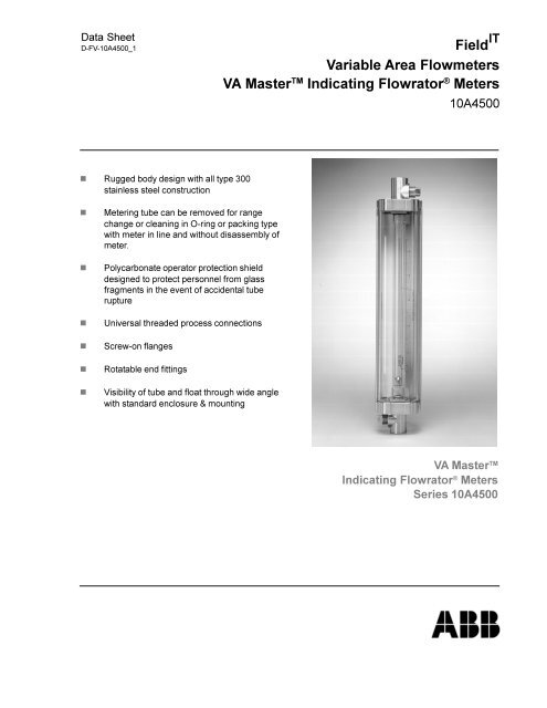
Data Sheet D-FV-10A4500_1 Field IT Variable Area Flowmeters VA Master TM Indicating Flowrator ® Meters 10A4500 n Rugged body design with all type 300 stainless steel construction n n n n n n Metering tube can be removed for range change or cleaning in O-ring or packing type with meter in line and without disassembly of meter. Polycarbonate operator protection shield designed to protect personnel from glass fragments in the event of accidental tube rupture Universal threaded process connections Screw-on flanges Rotatable end fittings Visibility of tube and float through wide angle with standard enclosure & mounting VA Master TM Indicating Flowrator ® Meters Series 10A4500
- Page 2 and 3: Variable Area Flowmeters VA Master
- Page 4 and 5: Variable Area Flowmeters VA Master
- Page 6 and 7: Variable Area Flowmeters VA Master
- Page 8 and 9: Variable Area Flowmeters VA Master
- Page 10: Variable Area Flowmeters VA Master
Data Sheet<br />
D-FV-<strong>10A4500</strong>_1<br />
Field IT<br />
Variable Area Flowmeters<br />
VA Master TM Indicating Flowrator ® Meters<br />
<strong>10A4500</strong><br />
n Rugged body design with all type 300<br />
stainless steel construction<br />
n<br />
n<br />
n<br />
n<br />
n<br />
n<br />
Metering tube can be removed for range<br />
change or cleaning in O-ring or packing type<br />
with meter in line and without disassembly of<br />
meter.<br />
Polycarbonate operator protection shield<br />
designed to protect personnel from glass<br />
fragments in the event of accidental tube<br />
rupture<br />
Universal threaded process connections<br />
Screw-on flanges<br />
Rotatable end fittings<br />
Visibility of tube and float through wide angle<br />
with standard enclosure & mounting<br />
VA Master TM<br />
Indicating Flowrator ® Meters<br />
Series <strong>10A4500</strong>
Variable Area Flowmeters<br />
VA Master TM Indicating FLOWRATOR ® Meters<br />
VA MASTER<br />
INDICATING FLOWRATOR ® METERS<br />
The ABB Series VA Master Flowrator meter is a<br />
glass tube variable-area flowmeter providing visual<br />
indication of flow rate over a 12-1/2 to 1 range on a<br />
linear scale. Seals in the meter can be either O-ring<br />
or packing gland type to suit the application.<br />
With either type of seal, the glass meter tube can be<br />
removed easily for range change or cleaning,<br />
without disassembling the end fittings or removing<br />
the meter from the line. Both types have the same<br />
external dimensions and are interchangeable with<br />
regard to piping assembly. Also available with one or<br />
two bistable alarms to give contact closure (or<br />
opening) on rising or falling flow.<br />
Universal threaded process connections allow the<br />
meter to be installed with either horizontal or vertical<br />
piping arrangements. Screw-on flanges provide the<br />
maximum in versatility.<br />
The meter is available in tube sizes from 1/2-inch<br />
through 2-inch bore for liquid or gas service.<br />
Engineering Specifications<br />
Repeatability: 0.5% of full scale.<br />
Accuracy: Standard is ±2% of maximum flow.<br />
Calibrated standard is ±1% of maximum flow.<br />
Range: 12-1/2 to 1<br />
Mounting: Standard — line mounting;<br />
Optional — panel mounting (flush, surface).<br />
Scales<br />
Tube Sizes,<br />
Inches<br />
½ thru 2<br />
Nominal<br />
Length<br />
10-in. (250 mm)<br />
½-50 (only) 9-in. (227 mm)<br />
Scale<br />
Materials of Construction:<br />
Type and Location<br />
Percentage on tube<br />
or Direct Reading on<br />
external metal scale<br />
with blank tube<br />
Tube: Beadguide borosilicate glass<br />
USV, SV, NSV Floats: Type 316 stainless steel;<br />
O-rings: Standard - Buna N; Optional - Viton, EPR<br />
Packing: Standard - Neoprene; Optional - molded<br />
Teflon liner.<br />
Fittings: Type 316 stainless steel<br />
Plugs: 316 stainless steel<br />
Float Stops: Teflon<br />
Tube Rest Gaskets:<br />
Standard - Klinger-Sil<br />
Optional - Teflon (10A4600 only)<br />
Electrical Specifications for Alarms<br />
D-FV-<strong>10A4500</strong>_1<br />
Supply Voltage: 120V ac ±15%, 45-65 Hz<br />
Contact Rating: Max. 250V; Max. 2A<br />
Sensor Switch Cable: Standard - 6.5 feet<br />
Optional - up to 980 feet<br />
Safety Classification: The sensor(s) is intrinsically<br />
safe for Class I, Div. 1, Group A, B, C & D and Class<br />
II, Div. 1, Group E, F & G when connected with control<br />
amplifier mounted in non-hazardous location.<br />
Service Conditions<br />
Applications: Glass tube meters are not recommended<br />
for continuous service on alkalis above<br />
100ºF (38ºC) or more than 20% concentrations; nor<br />
for fluorine, hydrofluoric acid, water above 200ºF<br />
(93ºC), steam, slurries, or molten metal.<br />
Temperature Ratings: Minimum recommended process<br />
fluid temperature is 32ºF (0ºC). Maximum recommended<br />
process fluid temperature is 250ºF<br />
(121ºC).<br />
Ambient Temperature Range: 32ºF to 140ºF<br />
Pressure Ratings:<br />
Maximum Safe<br />
Working Pressure<br />
Tube Size (inches) @ 100ºF (38ºC)<br />
psig<br />
kPa<br />
gauge<br />
½ NPT 300 2069<br />
½ Flanged; Stainless Steel 275 1896<br />
¾ All 200 1379<br />
1 All 200 1379<br />
1½ All 130 896<br />
2 All 100 689<br />
CAUTION<br />
Is it important that the O-ring material be compatible with the<br />
process fluid. Meter tube breakage can occur if the wrong<br />
material is used. For example: VITON O-RING MUST NEVER<br />
BE USED FOR AMMONIA SERVICE.<br />
Weights and Connection<br />
Tube Conn. Threaded Flanged*<br />
Size Size<br />
Weight<br />
(inches) (inches) lb kg lb kg<br />
½ ½ 8.5 3.9 12 5.5<br />
¾, 1 ¾ NPT 17 7.5 -- --<br />
¾, 1 1 Flgd -- -- 21 9.5<br />
1 ½, 2 1 ½ 29 13 35 16<br />
*Flanges match drilling of ANSI Class 125/150 Flanges.<br />
2
Variable Area Flowmeters<br />
VA Master TM Indicating FLOWRATOR ® Meters<br />
D-FV-<strong>10A4500</strong>_1<br />
Meter Sizing<br />
For sizing flowmeters when the required flow is of<br />
liquid (density 1.0 g/mL), or of gas (sp. gr. of air and<br />
at 14.7 psia and 70ºF or 101.3 kPa abs and 21ºC)<br />
the capacity table may be entered directly.<br />
The conversion equations shown permit the capacity<br />
tables to be used for other operating conditions,<br />
and apply to all Capacity Tables shown with Type<br />
316 Stainless Steel Floats.<br />
Liquid Conversion<br />
or<br />
where:<br />
gpm = desired maximum flow rate in gpm<br />
lbs/min = desired maximum flow rate in pounds per<br />
minute<br />
ρ = fluid density, g/cc at operating conditions<br />
gpm H 2<br />
O = equivalent flow rate in gpm H 2<br />
O<br />
Gas Conversion<br />
scfm air spgr x 14.7 x Top<br />
at 14.7 psia = scfm 1.0 x Pop x 530<br />
and 70ºF<br />
or<br />
gpm H 2O<br />
= gpm<br />
gpm H 2O<br />
=<br />
lbs/min.<br />
8.33 x<br />
7.02<br />
8.02<br />
7.02 x<br />
8.02 −<br />
scfm air<br />
1.0 x 14.7 x Top<br />
at 14.7 psia = lbs/min x 13.34 sp gr x Pop x 530<br />
and 70ºF<br />
Where:<br />
scfm =<br />
sp gr =<br />
T op<br />
=<br />
P op<br />
=<br />
x<br />
−<br />
desired maximum flow rate in scfm<br />
specific gravity of gas at standard<br />
temperature and pressure, referenced to<br />
air at standard temperature and pressure<br />
(14.7 psia and 70ºF)<br />
absolute temperature, (460 +ºF) at<br />
operating conditions<br />
absolute pressure in psia at operating<br />
conditions<br />
scfm air = equivalent flow rate in scfm of air at<br />
14.7 psia and 70ºF with stainless steel float<br />
WARNING<br />
These meters must not be operated without the operator<br />
protection shield in place. To do so could result in injury to<br />
personnel.<br />
Accessories<br />
Metal Scale Plate(s): Graduated metal scale plate<br />
mounted adjacent to metering tube.<br />
Alarms: One or two* bi-stable alarm switches,<br />
adjustable over entire scale length to give contact<br />
closure (or opening) upon rising or falling flow.<br />
Available with SPDT or DPDT switch action.<br />
*Note when using two switches, the minimum spacing is on 1" centers<br />
(approx. 10% of full scale).<br />
Surface (Front) Panel Mounting: Nuts, bolts, and<br />
lock washers for mounting meter against front of<br />
panel by means of mounting holes provided in<br />
every meter body.<br />
Flush (Rear) Panel Mounting: Brackets, bezel and<br />
hardware for mounting meter behind panel.<br />
Welded Flanges: Upon request, flanges - nipples -<br />
end fittings can be supplied as a welded assembly.<br />
Ordering Information<br />
To eliminate any delays in the processing of orders<br />
and to insure prompt delivery, please specify:<br />
Complete Model Number<br />
Accuracy Desired<br />
Alarm Settings if applicable<br />
Operating Conditions<br />
<strong>Fluid</strong> Measured<br />
Maximum Flow Rate and Unit of Flow<br />
<strong>Fluid</strong> Density<br />
<strong>Fluid</strong> Viscosity<br />
Allowable Pressure Drop<br />
Operating and Maximum Temperature<br />
Operating and Maximum Pressure<br />
3
Variable Area Flowmeters<br />
VA Master TM Indicating FLOWRATOR ® Meters<br />
D-FV-<strong>10A4500</strong>_1<br />
Capacity Table (Low Pressure Drop Design)<br />
Tube Size<br />
(Inch)<br />
1/2”<br />
3/4”<br />
1”<br />
1½”<br />
2”<br />
Maximum Flow<br />
Float Number Total ∆P V.I.C. psia Critical<br />
gpm H2O scfm Air Tube Number<br />
(316 sst) (See Note 1) (See Note 2) (See Note 3)<br />
Equiv. Equiv.<br />
0.198 0.800 FP-1/2-17-G-10 1/2-GUSVT-410 0.53 2.2 3.6<br />
0.238 0.982 FP-1/2-21-G-10 1/2-GUSVT-410 0.53 2.2 3.6<br />
0.324 1.339 FP-1/2-27-G-10 1/2-GUSVT-410 0.58 2.2 3.6<br />
0.436 1.796 FP-1/2-35-G-10 1/2-GUSVT-410 1.0 2.2 3.6<br />
0.825 3.40 FP-1/2-50-G-9 1/2-GUSVT-410 2.0 2.2 3.6<br />
0.633 2.62 FP-3/4-21-G-10 3/4-GUVT-510 0.60 3.3 3.1<br />
0.860 3.54 FP-3/4-27-G-10 3/4-GUVT-510 0.71 3.3 1.5<br />
1.205 4.98 FP-1-27-G-10 1-GUSVT-611 1.28 4.00 1.0<br />
1.67 6.90 FP-1-35-G-10 1-GUSVT-611 1.83 4.00 0.75<br />
2.58 10.70 FP-1-27-G-10 1-GUSVT-610 5.47 8.6 4.5<br />
3.60 14.84 FP-1-35-G-10 1-GUSVT-610 7.97 8.6 3.4<br />
2.45 10.30 FP-1½ - 21-G-10 1½ - GUSVT–867 0.92 6.5 1.0<br />
3.33 13.80 FP-1½ - 27-G-10 1½ - GUSVT–867 1.24 6.5 1.0<br />
6.50 27.00 FP-1½ - 21-G-10 1½ - GUSVGT-814 5.75 16.2 6.8<br />
8.70 36.00 FP-1½ - 27-G-10 1½ - GUSVGT-814 7.20 16.2 6.8<br />
5.54 22.90 FP-2-27-G-10 2-GUSVT-913 1.65 8.9 1.0<br />
13.75 56.70 FP-2-27-G-10 2-GUSVT-914 9.00 22.0 6.2<br />
Note: Standard percent scales are not applicable to low pressure drop floats.<br />
Notes:<br />
1. Pressure drop is total pressure loss across the meter at100% flow rate in inches of water column.<br />
2. Meter is unaffected by viscosity when the value of cps/ Ö r (using r = operating density in g/cc and cps = viscosity in centipoises) is less than V.I.C.<br />
(viscosity immunity ceiling). V.I.C. is applicable to liquids only; all gas flows fall below Viscosity Immunity Ceiling.<br />
3. Meters are not recommended for gas service where pressure is below minimum shown. A flow throtting valve close coupled to meter outlet is<br />
recommended for all gas applications.<br />
4
Variable Area Flowmeters<br />
VA Master TM Indicating FLOWRATOR ® Meters<br />
D-FV-<strong>10A4500</strong>_1<br />
CAPACITY TABLE<br />
Bead Guide Meters with USV, SV and NSV Floats<br />
Tube<br />
Size<br />
(Inch)<br />
1/2”<br />
3/4”<br />
1”<br />
1½”<br />
2”<br />
Maximum Flow<br />
Float Number Total ∆P V.I.C. psia Critical<br />
gpm H 2O scfm Air Tube Number<br />
(316 sst) (See Note 1) (See Note 2) (See Note 3)<br />
Equivalent Equivalent<br />
0.267 1.10 FP-1/2-17-G-10 1/2-GUSVT-40A 1.2 2.9 5.5<br />
0.328 1.35 FP-1/2-21-G-10 1/2-GUSVT-40A 1.4 2.9 3.5<br />
0.442 1.82 FP-1/2-27-G-10 1/2-GUSVT-40A 2.0 2.9 2.7<br />
0.480 1.92 FP-1/2-17-G-10 1/2-GSVT-45A 3.5 5.1 17.9<br />
0.600 2.47 FP-1/2-21-G-10 1/2-GSVT-45A 4.6 5.1 11.5<br />
0.619 2.55 FP-1/2-35-G-10 1/2-GUSVT-40A 3.1 2.9 2.0<br />
0.670 2.76 FP-1/2-17-G-10 1/2-GSVT-44A 6.4 7.1 33.4<br />
0.690 2.85 FP-1/2-17-G-10 1/2-GSVT-48A 7.3 7.6 39.0<br />
0.810 3.35 FP-1/2-27-G-10 1/2-GSVT-45A 6.8 5.1 8.4<br />
0.830 3.42 FP-1/2-21-G-10 1/2-GSVT-44A 7.7 7.1 33.8<br />
0.880 3.62 FP-1/2-21-G-10 1/2-GSVT-48A 8.0 7.6 24.6<br />
0.885 3.65 FP-1/2-17-G-10 1/2-GNSVT-48A 8.2 1.1 19.8<br />
1.10 4.52 FP-1/2-21-G-10 1/2-GNSVT-48A 9.9 1.1 20.0<br />
1.12 4.60 FP-1/2-27-G-10 1/2-GSVT-44A 12.3 7.1 16.2<br />
1.15 4.74 FP-1/2-35-G-10 1/2-GSVT-45A 8.2 5.1 8.5<br />
1.19 4.90 FP-1/2-27-G-10 1/2-GSVT-48A 13.7 7.6 18.6<br />
1.44 5.93 FP-1/2-27-G-10 1/2-GNSVT-48A 15.8 1.1 16.5<br />
1.56 6.43 FP-1/2-35-G-10 1/2-GSVT-44A 14.8 7.1 16.5<br />
1.66 6.85 FP-1/2-35-G-10 1/2-GSVT-48A 17.2 7.6 18.8<br />
2.00 8.24 FP-1/2-50-G-9 1/2-GSVT-45A 12.0 5.1 4.0<br />
2.76 11.4 FP-1/2-50-G-9 1/2-GSVT-44A 31.0 7.1 7.7<br />
2.90 12.0 FP-1/2-50-G-9 1/2-GSVT-48A 35.2 7.6 8.9<br />
3.52 14.5 FP-1/1-50-G-9 1/2-GNSVT-48A 52.0 1.1 8.8<br />
1.96 8.1 FP-3/4-21-G-10 3/4-GSVGT-54A 5.3 10.4 13.9<br />
2.49 10.2 FP-3/4-21-G-10 3/4-GNSVGT-54A 6.8 1.6 13.9<br />
2.66 11.0 FP-3/4-21-G-10 3/4-GSVGT-59A 7.0 14.1 28.7<br />
2.70 11.1 FP-3/4-27-G-10 3/4-GSVGT-54A 7.7 10.4 9.6<br />
3.37 13.9 FP-3/4-21-G-10 3/4-GNSVGT-59A 11.5 2.1 25.3<br />
3.55 14.6 FP-3/4-27-G-10 3/4-GNSVGT-54A 11.5 1.6 9.6<br />
3.67 15.1 FP-3/4-27-G-10 3/4-GSVGT-59A 13.7 14.0 19.8<br />
4.80 19.8 FP-3/4-27-G-10 3/4-GNSVGT-59A 20.5 2.1 19.8<br />
4.25 17.5 FP-1-27-G-10 1-GSVGT-64A 12.9 14.8 11.5<br />
4.82 19.9 FP-1-27-G-10 1-GSVGT-68A 18.7 16.9 15.6<br />
5.63 23.2 FP-1-27-G-10 1-GNSVGT-64A 20.7 2.2 11.3<br />
6.00 24.7 FP-1-35-G-10 1-GSVGT-64A 24.6 14.8 6.8<br />
6.46 26.6 FP-1-27-G-10 1-GNSVGT-68A 32.5 2.5 15.6<br />
6.80 28.0 FP-1-35-G-10 1-GSVGT-68A 37.0 16.9 8.9<br />
7.62 31.4 FP-1-27-G-10 1-GNSVGT-69A 75.0 1.5 22.2<br />
7.84 32.4 FP-1-35-G-10 1-GNSVGT-64A 37.7 2.2 6.8<br />
9.00 37.0 FP-1-35-G-10 1-GNSVGT-68A 62.8 2.5 8.9<br />
9.50 39.2 FP-1-35-G-10 1-GSVGT-69A 65.3 8.5 13.4<br />
11.0 45.3 FP-1-35-G-10 1-GNSVGT-69A 112.0 1.5 13.4<br />
13.2 54.4 FP-1½ - 27-G-10 1½ - GSVGT-87A 9.5 27.6 15.4<br />
14.6 60.0 FP-1½ -27-G-10 1½ - GSVGT-86A 13.5 31.0 22.0<br />
17.6 72.0 FP-1½ -27-G-10 1½ - GNSVGT-87A 12.8 4.20 15.4<br />
18.6 76.5 FP-1½ -27-G-10 1½ - GNSVGT-86A 15.2 4.80 22.0<br />
24.0 99.0 FP-2-27-G-10 2-GSVGT-97A 24.0 26.5 16.4<br />
30.0 123.8 FP-2-27-G-10 2-GSVGT-98A 34.0 18.5 21.2<br />
32.0 132.0 FP-2-27-G-10 2-GNSVGT-97A 32.0 3.0 16.4<br />
36.1 149.0 FP-2-27-G-10 2-GNSVGT-98A 45.0 3.30 21.2<br />
48.0(5) - FP-2-27-G-10 BL-954 70.0 2.0 -<br />
60.0(5) - FP-2-27-G-10 BL-953 95.0 2.0 -<br />
68.0(5) - FP-2-27-G-10 BL-950 110.0 2.0 -<br />
90(5) - FP-2-27-G-10 BL-951 192.7 1.0 -<br />
Note: 1. Pressure drop is total pressure loss across the meter at 100% flow rate in inches of water column.<br />
2. Meter is unaffected by viscosity when the value of cps/ Ö r using r = operating density in g/cc and cps = viscosity in centipoises) is less than<br />
V.I.C. (viscosity immunity ceiling). V.I.C. is applicable to liquids only; all gas flows fall below Viscosity Immunity Ceiling.<br />
3. Meters are not recommended for gas service where pressure is below minimum shown. For such applications use low pressure drop capacity<br />
table. A flow throtting valve close coupled to meter outlet is recommended for all gas applications.<br />
4. Unless other shown, Range is equal to or greater than 12.5:1<br />
5. Short Range Floats; BL-954 is 8:1; BL-953 is 3.5:1; BL-950 & Bl-951 are 3:1.<br />
5
Variable Area Flowmeters<br />
VA Master TM Indicating FLOWRATOR ® Meters<br />
D-FV-<strong>10A4500</strong>_1<br />
CAPACITY TABLE<br />
Meters with Alarm Option<br />
Tube<br />
Size<br />
(Inch)<br />
1/2”<br />
3/4”<br />
1”<br />
1½”<br />
2”<br />
Maximum Flow<br />
Range<br />
Float Number Total ∆P V.I.C. psia Critical<br />
gpm Liquid scfm Air Tube Number<br />
(See Note<br />
(316 sst) (See Note 1) (See Note 2) (See Note 3)<br />
sp. gr. 1.0 @ STP<br />
4)<br />
0.670 2.76 FP-1/2-17-G-10 1/2-GSVTA-44 6.4 7.1 33.4<br />
0.690 2.85 FP-1/2-17-G-10 1/2-GSVTA-48 7.3 7.6 39.0 11.1:1<br />
0.830 3.42 FP-1/2-21-G-10 1/2-GSVTA-44 7.7 7.1 33.8<br />
0.880 3.62 FP-1/2-21-G-10 1/2-GSVTA-48 8.0 7.6 24.6<br />
0.885 3.65 FP-1/2-17-G-10 1/2-GNSVTA-48 8.2 1.1 19.8 11.1:1<br />
1.03 4.24 FP-1/2-21-G-10 1/2-GNSVTA-44 8.9 1.1 33.4<br />
1.10 4.52 FP-1/2-21-G-10 1/2-GNSVTA-48 9.9 1.1 20.0<br />
1.12 4.60 FP-1/2-27-G-10 1/2-GSVTA-44 12.3 7.1 16.2<br />
1.19 4.90 FP-1/2-27-G-10 1/2-GSVTA-48 13.7 7.6 18.6<br />
1.44 5.93 FP-1/2-27-G-10 1/2-GNSVTA-48 15.8 1.1 16.5<br />
1.56 6.43 FP-1/2-35-G-10 1/2-GSVTA-44 14.8 7.1 16.5<br />
1.66 6.85 FP-1/2-35-G-10 1/2-GSVTA-48 17.2 7.6 18.8<br />
1.84 7.60 FP-1/2-27-G-10 1/2-GNSVTA-43 18.5 1.3 27.5 7.1:1<br />
2.00 8.24 FP-1/2-35-G-10 1/2-GNSVTA-48 19.0 1.1 8.8<br />
2.43 10.0 FP-1/2-35-G-10 1/2-GNSVTA-43 30.0 1.3 22.7 7.1:1<br />
2.76 11.4 FP-1/2-50-G-9 1/2-GSVTA-44 31.0 7.0 7.7<br />
2.90 12.0 FP-1/2-50-G-9 1/2-GSVTA-48 35.2 7.6 8.9<br />
3.52 14.5 FP-1/2-50-G-9 1/2-GNSVTA-48 52.0 1.1 8.8<br />
4.00 16.0 FP-1/2-50-G-9 ½-GNSVTA-43 72.0 1.3 12.3 10.0:1<br />
1.96 8.1 FP-3/4-21-G-10 3/4-GSVTA-54 5.3 10.4 13.9<br />
2.49 10.2 FP-3/4-21-G-10 3/4-GNSVTA-54 6.8 1.6 13.9<br />
2.70 11.1 FP-3/4-27-G-10 3/4-GSVTA-54 7.7 10.4 9.6<br />
3.15 13.0 FP-3/4-21-G-10 3/4-GSVTA-53 11.0 16.6 36.0 4.8:1<br />
3.55 14.6 FP-3/4-27-G-10 3/4-GNSVTA-54 11.5 1.6 9.6<br />
3.85 15.8 FP-3/4-27-G-10 3/4-GSVTA-56 12.0 14.9 19.8 7.7:1<br />
4.35 18.0 FP-3/4-27-G-10 3/4-GSVTA-53 13.0 16.8 25.0 5.3:1<br />
5.05 20.8 FP-3/4-27-G-10 3/4-GNSVTA-56 14.0 2.2 19.8 7.7:1<br />
5.70 23.6 FP-3/4-27-G-10 3/4-GNSVTA-53 16.0 2.5 25.0 5.3:1<br />
4.25 17.5 FP-1-27-G-10 1-GSVTA-64 12.9 14.8 11.5<br />
4.82 19.8 FP-1-27-G-10 1-GSVTA-65 15.0 16.9 14.8 8.3:1<br />
5.63 23.2 FP-1-27-G-10 1-GNSVTA-64 20.7 2.2 11.3<br />
6.00 24.7 FP-1-35-G-10 1-GSVTA-64 24.6 14.8 6.8<br />
6.75 27.9 FP-1-35-G-10 1-GSVTA-65 27.0 16.9 8.9 10:1<br />
7.84 32.4 FP-1-35-G-10 1-GNSVTA-64 37.7 2.2 6.8<br />
8.46 35.1 FP-1-35-G-10 1-GSVTA-63 45.0 20.8 13.9 4.3:1<br />
9.0 36.9 FP-1-35-G-10 1-GNSVTA-65 62.8 2.5 8.9<br />
9.9 40.6 FP-1-35-G-10 1-GSVTA-66 75.0 8.5 13.4 9.1:1<br />
10.8 44.5 FP-1-35-G-10 1-GNSVTA-66 112 1.5 14.5 9.1:1<br />
11.1 45.7 FP-1-35-G-10 1-GNSVTA-63 120 2.9 13.1 4.3:1<br />
13.4 55.0 FP-1½ -27-G-10 1½ - GSVTA-84 10.0 27.6 15.4<br />
15.4 63.5 FP-1½ -27-G-10 1½ - GSVTA-85 14.0 32.0 20.3 6.2:1<br />
16.0 66.0 FP-1½ -27-G-10 1½ - GSVTA-83 16.0 33.0 22.0 5.3:1<br />
17.6 72.0 FP-1½ -27-G-10 1½ - GNSVTA-84 15.0 4.2 15.4<br />
20.4 84.0 FP-1½ -27-G-10 1½ - GNSVTA-85 18.0 5.0 20.3 6.2:1<br />
21.2 87.0 FP-1½ -27-G-10 1½ - GNSVTA-83 20.0 4.9 22.0 5.3:1<br />
23.9 99.0 FP-2-27-G-10 2-GSVTA-94 24.0 40.5 16.4 6.7:1<br />
27.9 115.2 FP-2-27-G-10 2-GSVTA-93 30.0 49.0 24.0 3.6:1<br />
31.5 129.8 FP-2-27-G-10 2-GNSVTA-94 32.0 6.1 17.4 6.7:1<br />
36.9 152.1 FP-2-27-G-10 2-GNSVTA-96 47.0 7.6 21.2 7.1:1<br />
38.2 156.6 FP-2-27-G-10 2-GNSVTA-93 50.0 7.3 24.0 3.6:1<br />
Note: 1. Pressure drop is total pressure loss across the meter at 100% flow rate in inches of water column.<br />
2. Meter is unaffected by viscosity when the value of cps/Ö r using r = operating density in g/cc and cps = viscosity in centipoises)<br />
is less than V.I.C. (viscosity immunity ceiling). V.I.C. is applicable to liquids only; all gas flows fall below Viscosity Immunity Ceiling.<br />
3. Meters are not recommended for gas service where pressure is below minimum shown. For such applications use low pressure<br />
drop capacity table. A flow throtting valve close coupled to meter outlet is recommended for all gas applications.<br />
4. Unless other shown, Range is equal to or greater than 12.5:1<br />
5. Short Range Floats; BL-954 is 8:1; BL-953 is 3.5:1; BL-950 & Bl-951 are 3:1.<br />
6
Variable Area Flowmeters<br />
VA Master TM Indicating FLOWRATOR ® Meters<br />
D-FV-<strong>10A4500</strong>_1<br />
Dimension Drawings<br />
Meter<br />
Tube Size<br />
1/2” 3/4” to 1” 1-1/2” to 2”<br />
Meter<br />
Tube Size<br />
1/2” 3/4” to 1” 1-1/2” to 2”<br />
Dim. Inch mm Inch mm Inch mm<br />
A 19-5/16 490 21-3/16 538 26-7/15 671<br />
B 16-1/2 419 17-1/2 445 20-1/2 521<br />
C 1-13/32 37 1-27/32 47 2-31/32 75<br />
D 3-1/2 89 4 103 5 127<br />
E 3-3/8 86 4-3/8 111 5-11/16 144<br />
F 2-5/8 67 3-27/64 87 4-7/8 124<br />
G 8-1/4 210 8-3/4 222 10-1/4 260<br />
L 1-1/2 38 1-59/64 49 2-5/8 67<br />
M 1-1/4 32 1-1/2 38 2-1/2 64<br />
N 1/2 13 3/4 19 1-1/2 38<br />
P 3/4 19 1-1/8 29 1-7/8 48<br />
Q 1/2 13 1 25 1-1/2 38<br />
Dim. Inch mm Inch mm Inch mm<br />
A 18-9/16 471 20 508 24-5/16 618<br />
B 20-5/8 524 22-1/8 562 27-11/16 703<br />
C 2-21/32 68 3-5/32 80 5-7/32 133<br />
D 1-5/8 41 2-3/32 53 3-17/32 90<br />
E 3-3/8 86 4-3/8 111 5-11/16 144<br />
F 2-5/8 67 3-27/64 87 4-7/8 124<br />
G 7-21/32 194 7-29/32 201 8-5/8 219<br />
L 1-1/2 38 1-59/64 49 2-5/8 67<br />
M 1-1/4 32 1-1/2 38 2-1/2 64<br />
N 1/2 13 3/4 19 1-1/2 38<br />
P 3/4 19 1-1/8 29 1-7/8 48<br />
Q 1/2 13 1 25 1-1/2 38<br />
7
Variable Area Flowmeters<br />
VA Master TM Indicating FLOWRATOR ® Meters<br />
D-FV-<strong>10A4500</strong>_1<br />
FRONT PANEL MOUNTING<br />
FRONT PANEL MOUNTING<br />
<strong>10A4500</strong> / 4500 SERVICES<br />
Note: Front Panel Mounting Not Available with Alarms<br />
REAR PANEL MOUNTING<br />
Conn. Size 1/2” 3/4” & 1” 1-1/2”<br />
Scale<br />
Length<br />
10” 10” 10”<br />
Dim. Inch mm Inch mm Inch mm<br />
A 16-3/16 411 16-3/16 411 17-3/4 451<br />
B 4-9/16 116 5-1/4 133 6-1/8 156<br />
C 2-5/8 67 3-7/16 87 4-7/8 124<br />
D 1-1/2 38 1-15/16 49 2-5/8 67<br />
E 5 127 5-15/16 151 7-5/8 200<br />
F 13-5/8 346 13-7/8 352 15-5/16 389<br />
G 2-11/16 68 3-3/8 86 4-1/4 108<br />
H 3-7/16 87 4-1/8 105 5 127<br />
J 14-7/16 367 14-13/16 376 16-1/4 413<br />
K 1-1/4 32 1-11/16 43 2-3/8 60<br />
8
Variable Area Flowmeters<br />
VA Master TM Indicating FLOWRATOR ® Meters<br />
MODEL NUMBER DESIGNATION<br />
D-FV-<strong>10A4500</strong>_1<br />
Variable Area Flowmeters 10A4 __ __ __ __ B__ __ __ __ __<br />
Pressure Seals<br />
O-ring Pressure Seals ...................................................................... 55<br />
Packing Gland Type Pressure Seals ................................................ 65<br />
Connection Designation<br />
Horizontal Threaded .................................................................................5<br />
Horizontal Flanged ...................................................................................6<br />
Vertical Threaded .....................................................................................7<br />
Vertical Flanged ........................................................................................8<br />
Scales<br />
Percent on Tube ............................................................................................. X<br />
Direct Reading on Tube .................................................................................. Y<br />
Direct Reading Metal Scale and Percent on Tube ......................................... E<br />
Percent on Metal Scale................................................................................... P<br />
Direct Reading Metal Scale ............................................................................ S<br />
Dual Direct Reading Metal Scales .................................................................. D<br />
Panel Mounting<br />
Line Mounted .......................................................................................................... X<br />
Front Panel Mounted .............................................................................................. Y<br />
Rear (Flush) Panel Mounted .................................................................................. Z<br />
Design Level ........................................................................................................................ B<br />
Sizes (inches)<br />
Conn. Size<br />
Tube Size<br />
1/2 1/2 ..................................................................................................... H<br />
3/4 (NPT) 3/4 ..................................................................................................... J<br />
3/4 (NPT) 1 ........................................................................................................ K<br />
1 (Flgd) 3/4 ..................................................................................................... L<br />
1 (Flgd) 1 ........................................................................................................ M<br />
1-1/2 1-1/2 .................................................................................................. N<br />
1-1/2 2 ........................................................................................................ P<br />
Fitting Material<br />
316 Stainless Steel .......................................................................................................................C<br />
Seal Material<br />
Packaging Gland Design - Neoprene ................................................................................................. E<br />
Packaging Gland Design - Teflon ....................................................................................................... D<br />
O-ring Design - Buna-N ...................................................................................................................... F<br />
O-ring Design - Viton .......................................................................................................................... H<br />
O-ring Design EPR ............................................................................................................................. J<br />
Connection Type<br />
NPT ............................................................................................................................................................ B<br />
R.F. Flange Class 150 (316 sst only) ....................................................................................................... D<br />
Alarms<br />
Not Required...................................................................................................................................................... X<br />
Low Alarm (SPDT) ............................................................................................................................................. C<br />
High Alarm (SPDT) ............................................................................................................................................ B<br />
High & Low Alarm (SPDT) ................................................................................................................................. D<br />
Low Alarm (DPDT) ............................................................................................................................................. F<br />
High Alarm (DPDT) ............................................................................................................................................ E<br />
High & Low Alarm (DPDT) ................................................................................................................................. G<br />
High & High Alarm (SPDT) ................................................................................................................................ H<br />
Low & Low Alarm (SPDT) .................................................................................................................................. J<br />
High & High Alarm (DPDT) ................................................................................................................................ K<br />
Low & Low Alarm (DPDT) .................................................................................................................................. L<br />
9
Variable Area Flowmeters<br />
VA Master TM Indicating FLOWRATOR ® Meters<br />
D-FV-<strong>10A4500</strong>_1<br />
Notes<br />
ABB has Sales & Customer Support<br />
expertise in over 100 countries worldwide<br />
www.abb.com<br />
The Company’s policy is one of continuous product<br />
improvement and the right is reserved to modify the<br />
information contained herein without notice.<br />
Printed in USA (09.11.03)<br />
© ABB 2003<br />
D-FV-<strong>10A4500</strong>_1<br />
ABB Inc.<br />
125 East County Line Road<br />
Warminster<br />
PA 18974<br />
USA<br />
Tel: +1 215 674 6000<br />
Fax: +1 215 674 7183<br />
ABB Ltd<br />
Howard Road, St. Neots<br />
Cambridgeshire<br />
PE19 8EU<br />
UK<br />
Tel: +44 (0)1480 475321<br />
Fax: +44 (0)1480 217948<br />
10


