Long Tom Jumbo Manual PDF (9.6Mb) - Parts HeadQuarters Inc
Long Tom Jumbo Manual PDF (9.6Mb) - Parts HeadQuarters Inc
Long Tom Jumbo Manual PDF (9.6Mb) - Parts HeadQuarters Inc

You also want an ePaper? Increase the reach of your titles
YUMPU automatically turns print PDFs into web optimized ePapers that Google loves.
Page 1<br />
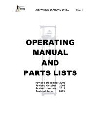
<strong>Long</strong> <strong>Tom</strong><br />
Drill Carrier<br />
<strong>Manual</strong><br />
Safety Procedures<br />
Operating Procedures<br />
Assembly and Maintenance Procedures<br />
<strong>Parts</strong> Schematics and <strong>Parts</strong> Lists<br />
Version 2013 03 26
Page 2<br />
Preface<br />
The manual is intended to provide users of <strong>Long</strong> <strong>Tom</strong> Drill <strong>Jumbo</strong>s with operating and<br />
maintenance instructions to maximize the operation of these machines. PHQ strives to<br />
provide highly productive light weight drill jumbos that are easy to use and maintain at a<br />
reasonable cost. This document contains instructions in assembly of components,<br />
schematic drawings and parts lists to enable the mechanical department to identify<br />
components and provide access to part numbers for ease of ordering replacements. The<br />
manual also provides basic instructions for tramming, steering and setting up the jumbo.<br />
Use the maintenance and repair manual of instructions for PHQ250 Jacklegs to care for<br />
the drills and one can gain significant operating instruction and information from the<br />
Operating <strong>Manual</strong> for PHQ250 Jacklegs.<br />
For information about any components not shown in the manual or any service issues<br />
which may arise in the use and maintenance of the <strong>Long</strong> <strong>Tom</strong> <strong>Jumbo</strong> please contact PHQ<br />
directly at the following address:<br />
<strong>Parts</strong> <strong>HeadQuarters</strong> <strong>Inc</strong>.<br />
Unit 2, 1175 Appleby Line<br />
Burlington, Ontario, Canada, L7L 5H9<br />
Tel: (905) 332-3271 Fax: (905) 332-9497<br />
E-mail: sales@partshq.com<br />
Website: www.partshq.com<br />
IMPORTANT NOTICE:<br />
<strong>Parts</strong> <strong>HeadQuarters</strong> is committed to continuous product improvements so all information,<br />
diagrams and part numbers in this manual are subject to revision. PHQ will endeavour to<br />
provide customers with due notice of any changes. The date of edition of the manual is<br />
identified by the version number shown on the lower left corner of each page in the<br />
manual. In the event of any discrepancy in part numbers or descriptions contact PHQ to<br />
ensure you have the most recent manual.<br />
Version 2013 03 26
Table of Contents<br />
Page 3<br />
1. Overview 4<br />
2. Carrier Styles and Dimensions 5<br />
2.1 Skid Steer………………………………………………………………………………………….. 5<br />
2.2 Rail Mount…………………………………………………………………………………………. 6<br />
2.3 Crawler……………………………………………………………………………………………… 7<br />
3. Specifications and Options 8<br />
3.1 Technical Data……………………………………………………………………………………. 8<br />
3.2 Standard Features……………………………………………………………………………….. 8<br />
3.3 Options…………………………………………………………………………………………….. 9<br />
4. Features and Tips 11<br />
4.1 Locking Valves…………….…………..…………………………………..…………………….. 11<br />
4.2 Sticking Jerky Cylinder………...……………………………………..……………………….. 12<br />
4.3 Safely Filling Lubricators……………………..……………………………………………….. 12<br />
4.4 Blow the Hoses…………………...……………………………………..……………………….. 12<br />
5. Preparing to Lift, Carry, Tow or Tram the <strong>Long</strong> <strong>Tom</strong>………………………… 12<br />
6. Lifting and Carrying the <strong>Jumbo</strong>…………………………………………………… 13<br />
7. Towing the <strong>Jumbo</strong>……………………………………………………………………. 14<br />
8. Tramming the <strong>Jumbo</strong>………………………………………………………………… 16<br />
9. Setting up the <strong>Jumbo</strong> to Drill and Drilling………………………………………. 18<br />
10. Drilling Tips and Safety Tips……………………………………………………….. 22<br />
11. Maintenance and Assembly – Carrier Skid Steer Schematic & <strong>Parts</strong> List 23<br />
12. Replacing the Chain Drive…………………………………………………………... 24<br />
13. Adjusting the Chain Drive…………………………………………………………… 25<br />
14, Mounting Bracket X1674 - Schematic and <strong>Parts</strong> List…………………………. 26<br />
15, Assembly of Mounting Bracket X1674……………………………………………. 28<br />
16. Balance Cylinder W1672 - Schematic and <strong>Parts</strong> List……………………………….. 29<br />
17. Assembly of Balance Cylinder W1672……………………………………………. 32<br />
18. Leg Cylinder W2619 – Schematic and <strong>Parts</strong> List………………………………. 33<br />
19. Assembly of Leg Cylinder W2619…………………………………………………. 35<br />
20. Routine Maintenance and Lubrication…………………………………………… 40<br />
<strong>Long</strong> <strong>Tom</strong> Drive Train Pneumatic Schematic………………………………………… 41<br />
<strong>Long</strong> <strong>Tom</strong> Boom Pneumatic Schematic……………………………………………….. 42<br />
<strong>Long</strong> <strong>Tom</strong> Lift and Feed Controls……………………………………………………….. 43<br />
Version 2013 03 26
1. Overview<br />
Page 4<br />
1.1. Origins of the <strong>Long</strong> <strong>Tom</strong> Drill Carrier<br />
A cost-effective solution was required to reduce or reduce or eliminate the negative aspects of<br />
handheld drilling with Jackleg drills, including:<br />
• The fatiguing physical Labour required when working from uneven terrain<br />
• A high accident and injury frequency, especially muscle strains from fatigue<br />
• Low productivity resulting from frequent re-positioning of legs of drills<br />
• Difficulty in pulling drill steel from completed holes due to operating conditions<br />
1.2. Benefits<br />
• Removes the physical effort required to lift the drill and position the leg<br />
• Simplifies collaring holes, maintaining alignment, and moving from hole to hole.<br />
• Requires fewer changes of drills steel. Holes often collared with eight foot rods.<br />
• Faster drilling with a long stroke feed (no interruption needed to move legs).<br />
• Quicker movement from one hole to setup on to the next hole.<br />
• Drills held aloft by booms making it fast and easy to change drill steel.<br />
• Capable of drilling a 8 foot 2400 mm drill hole in one pass<br />
• Eliminates slippage of the end of the air leg on the drift floor.<br />
• Eliminates potential hazards to the operator due to steel breakage.<br />
• Powerful retract of the anchored leg pulls steel from hole much better.<br />
• Drills remain mounted on the jumbo when not in use (out of harms way).<br />
• No need to connect hoses at start of shift or disconnect hoses at the end.<br />
• The <strong>Jumbo</strong> trams right in to the work place and arrives at the face ready to drill<br />
• NOTE: Rail-mount style jumbos require a locomotive to provide tramming.<br />
• The jumbo is fully pneumatic powered with no pumps or hydraulic systems.<br />
• Maintenance is simplified in the basic mechanical design and air leg type maintenance<br />
1.3. Applications<br />
• Sub-level development (the <strong>Jumbo</strong> disassembles for transport up raises<br />
• On the level high-ball drift development (trackless or with track)<br />
• Ramping either up or down from level to level at 15 degree grades<br />
• Mechanized undercut and fill type mining production operations<br />
• Narrow-vein (Thin-seam) room and pillar mining production operations<br />
1.4. Customization<br />
<strong>Long</strong> <strong>Tom</strong> models may be customized according to the customer's wishes. The standard new<br />
skid steer model is equipped with two booms. PHQ can provide single or three boom units.<br />
Optional brackets are available increasing height or length of booms for greater face coverage.<br />
A platform which pulls out and folds to width is available to provide an operating floor for<br />
drillers to make it easier to reach to drill “back” holes at the roof of an eleven foot drift heading.<br />
Version 2013 03 26
Page 5<br />
2. Carrier Styles<br />
2.1 Skid-Steer<br />
The standard Skid-Steer carrier is a fully-mobile self-propelled solid rubber tired carrier suitable<br />
for most underground applications. The jumbo featuring two independent pneumatic motors<br />
driving the four wheels has impressive flexibility and mobility under most conditions required of<br />
trackless equipment in the work place. The unit mounts two jackleg drills on pneumatic booms.<br />
Version 2013 03 26
2. Carrier Styles<br />
Page 6<br />
2.3 Rail Mount<br />
For mining operations where there is an existing network of rails the rail-mount carrier is the<br />
most cost-effective option. The jumbo is equipped with three jacklegs mounted on the same<br />
booms as our standard skid-steer units. Face coverage remains the same however the third<br />
drill speeds up operations where the air supply is sufficient. The jumbo is built for a standard<br />
rail gauge of 24” (610 mm) however the width could be customized according to requirements.<br />
Version 2013 03 26
Page 7<br />
2. Carrier Styles<br />
2.3 Crawler<br />
For extremely challenging and rough terrain, additional power and traction may be necessary.<br />
PHQ has worked with customers to create a custom crawler style carrier. Like the skid-steer<br />
jumbos the crawler models are fully self-propelled however feature an extremely rugged trackbased<br />
design. Each of the tracks is independently driven and controlled allowing for great<br />
maneuverability, while offering the same range of boom motion as our other models.<br />
Please note: All Track Driven <strong>Long</strong> <strong>Tom</strong> <strong>Jumbo</strong>s are custom designed and built for specific<br />
requirements and to meet various applications as required. No general dimension drawing,<br />
specific technical information or schematic part drawings are provided until the units are built.<br />
Service and support for these units is provided on an individual basis to meet requirements.<br />
For more information contact PHQ at the address provided at the beginning of the manual.<br />
Version 2013 03 26
Page 8<br />
3. Specifications & Features<br />
3.1 Technical Data<br />
Length, Overall<br />
Width, Overall<br />
Height, Overall<br />
Weight<br />
Booms (Standard)<br />
Boom Length<br />
17 Feet (5.18 Meters)<br />
53 <strong>Inc</strong>hes (1346 mm)<br />
66 <strong>Inc</strong>hes (1676 mm)<br />
5,500 lbs (2495 kg)<br />
Two<br />
9 Feet (2.75 Meters) Retractable<br />
Standard Face Coverage 8 Feet Wide x 11 Feet in Height **<br />
Motor – Gear Box<br />
Spring-return Tramming Valves<br />
Drive Chain Size & Length<br />
Drill Adapters<br />
Four Tires<br />
Three Lubricators<br />
Air Consumption ***<br />
16AM13 GAST Gear Motor<br />
¾ inch (20mm) Inlet / Outlet<br />
#80 HD Chain, 11 Feet 2 <strong>Inc</strong>hes in Length<br />
C-109HD (fits PHQ 250 Drill)<br />
Solid Rubber 22 <strong>Inc</strong>hes (560 mm) Diameter<br />
JOY Football Type 2.7 Pint (1.5 Liter)<br />
380 f 3 /min (10.7 m 3 /min) @ 90 psi (6.2 Bar)<br />
* Technical Data: Specifications listed are based on the shipping dimensions of the carrier itself, with booms, goosenecks and<br />
drill adaptors attached in locked positions (i.e. not swung open or extended) however, these figures do not include drills or any<br />
optional equipment. ** Standard Face Coverage: Measures represent the maximum distances attainable under standard<br />
configuration and allowing the booms to swing open as far as possible. Additional width coverage of one extra foot may be<br />
gained by rotating the goosenecks 90º (6” per side). For additional height and width, please see the extender options featured<br />
on the next page. ***Air Consumption Represents full functionality of the jumbo including tramming, while using both drills.<br />
3.2 Standard Features<br />
General:<br />
One gooseneck per boom with drill adapter mounting a PHQ250 jackleg drill. (Alternate: AL67 drill)<br />
<strong>Jumbo</strong> connects to one air header and water header in the work place. (minimum 2” air line 1” water line)<br />
<strong>Jumbo</strong> requires minimum of a fifty foot 1 ½” diameter Bull Hose compressed air connection (not supplied).<br />
<strong>Jumbo</strong> is complete with all necessary onboard air and water hoses and control valves.<br />
Skid-Steer Carriers:<br />
Two standard nine foot retractable booms complete with feed cylinders and drill lubricators.<br />
Two reversible gearmotors with integral gear cases (20:1 ratio) and chain drive to axles.<br />
Two independent tramming air supply control valves to facilitate skid steering.<br />
Four durable solid rubber tires prevent punctures and provide rigidity<br />
A rigid platform provided at the back of the carrier for the operator to stand on while tramming<br />
Version 2013 03 26
3.3 Options<br />
<strong>Long</strong> <strong>Tom</strong> <strong>Jumbo</strong>s can be customized with the addition of the following options:<br />
Page 9<br />
Boom 12” Extender to expand the<br />
width of face coverage up to 12<br />
<strong>Inc</strong>hes (340 mm) per side. The<br />
extender increases face coverage<br />
allowing for 10 foot (3 meter) width x<br />
11 foot (3.4 meter) height<br />
Boom 15” Extender to expand the<br />
height of face coverage up to 15<br />
<strong>Inc</strong>hes (380 mm) per side. The<br />
extender increases face coverage<br />
allowing for 10 foot (3 meter) width<br />
by 12 foot (3.7 meter) height<br />
Operator’s Drilling Platform pulls<br />
out of the front end of the jumbo and<br />
folds out to provide the added height<br />
required to reach drill controls when<br />
drilling back holes.<br />
Pneumatic Turbine Lights are<br />
available to mount on the <strong>Long</strong> <strong>Tom</strong><br />
Drill Carrier to provide lighting to the<br />
work area and for tramming.<br />
Spare Boom A Skid Steer Two Boom<br />
Carrier can be modified to accept a<br />
third operating boom. The third boom<br />
will add 400lbs (181kg) in weight.<br />
Version 2013 03 26
Page 10<br />
3.3 Options Continued<br />
Towing Eyes are installed front and<br />
back on the <strong>Long</strong> <strong>Tom</strong> <strong>Jumbo</strong> to allow<br />
easy connection for towing using an<br />
extendable Tow Bar or a Chain.<br />
Boom Safety Chain. A hole is drilled<br />
in the web reinforcement of the boom<br />
extension to accommodate a “D” type<br />
shackle and the last link on a length<br />
of one inch chain with a hook on one<br />
end has the last link at the other end<br />
welded to the boom. Connect the<br />
hook into the shackles to ensure the<br />
boom does not extend accidently.<br />
Tool Box. A tool box can be welded<br />
to the rear of the Skid Steer Carrier<br />
above the operator’s platform to allow<br />
for storage of smaller spare parts and<br />
tools if required.<br />
Wheel Chock Holders (four) to store<br />
wheel chocks (four) when tramming<br />
the <strong>Long</strong> <strong>Tom</strong> can be installed to form<br />
mud flaps covering the drive wheels<br />
at each end of the wheel fenders.<br />
Clipboard Holder can be mounted at<br />
the back of the carrier to carry the<br />
operator’s manuals and shift notes.<br />
Version 2013 03 26
3.3 Options Continued<br />
Page 11<br />
Self-Rescuer Box can be added at the<br />
back of the <strong>Long</strong> <strong>Tom</strong> <strong>Jumbo</strong> to<br />
carry a PLC1200BK Self Rescuer<br />
Drill Steel Holders are attached to the top<br />
of each wheel fender. Different lengths of<br />
drills steels up to eight foot under the collar<br />
can be placed in the holders while drilling.<br />
Loose drill steels in the holders must be<br />
secured when tramming<br />
Extendible Towing Bar<br />
Eyelets are installed at the front and rear of<br />
the <strong>Long</strong> <strong>Tom</strong> where an Extendable Tow<br />
Bar can be affixed to tow the carrier. (see<br />
instructions for towing the <strong>Long</strong><strong>Tom</strong> on<br />
Page 17)<br />
4. Safety Features and Tips<br />
4.1. Locking Valves - Insert locking pins in the<br />
holes provided on all air and water supply valves<br />
when locking down the air and water to prevent a<br />
valve from accidently twisting open. PHQ<br />
recommends the use of “Whip-Checks” on large air<br />
supply hose connections. Wire Whip Checks<br />
encircle and grip ends of connections preventing<br />
pressurized hoses whipping around from high<br />
pressure of compressed air exiting the hose.<br />
Version 2013 03 26
4.2. Jerky Cylinder Action - When new the boom<br />
lift cylinders and extension cylinders “stick” causing<br />
the cylinder pistons to jerk in or out. Open the drill<br />
throttle with control handle in the lowest hammering<br />
position. Vibration helps to make the movement of<br />
the booms up and down and the extending and<br />
retracting of the feed piston in and out smoother.<br />
4.3. Safety Filling Lubricators – PHQ supplies<br />
safety filler caps on all our lubricators. To fill the<br />
lubricator with rock drill oil or rock drill grease undo<br />
the filler cap using a mine wrench. There will be an<br />
audible hiss of air if the lubricator is pressurized.<br />
Close the valve and blow the hose to relieve any<br />
pressure before removing the cap to fill lubricator.<br />
Page 12<br />
4.4. Always blow hoses and air lines before<br />
connecting. Air hoses must be “blown” every time<br />
before connecting to the <strong>Jumbo</strong> to clear any debris<br />
or water in the air lines. Water hoses should be<br />
briefly flushed before connecting to be sure there is<br />
no debris in the water hoses. The air supply and<br />
water supply to the <strong>Jumbo</strong> should be turned off<br />
whenever the <strong>Jumbo</strong> is not in use. Drain water<br />
hoses if there is danger of freezing temperatures.<br />
5. Preparing to Lift, Carry, Tow or Tram the <strong>Long</strong> <strong>Tom</strong><br />
5.1. Lock the boom extensions from accidently<br />
extending while the jumbo is tramming. Connect<br />
the hooks of the safety chains to the shackles on<br />
the two booms extensions.<br />
5.2 Secure the booms in the support brackets<br />
provided at the front of the carrier as close as<br />
possible together.<br />
5.3 Secure support chains from the main<br />
cylinder to the leg extension by wrapping the<br />
chain around the hook on the leg. Avoid pinch<br />
points on the booms when moving the booms.<br />
Version 2013 03 26
Page 13<br />
5.4 Store The Wheel Cocks in the four holders<br />
provided.<br />
5.5 Secure Drill Steel in the steel holder by<br />
snuggly wrapping rope or strap around the steel<br />
in the holder. Be sure drill steels cannot slip out<br />
when moving the carrier.<br />
5.6. Disconnect the water supply from the<br />
main mine water header and coil on the jumbo<br />
or transport separately.<br />
6 Lifting and Carrying the <strong>Jumbo</strong><br />
6.1. It is possible to pick up the carrier and carry<br />
the <strong>Jumbo</strong> in the bucket of a large scoop tram or<br />
fork lift truck. Always securely chain the carrier<br />
to the bucket of the scoop tram or forks of the lift<br />
truck using the chain hooks provided on the<br />
pedestal tower of the drill carrier. There is no<br />
need to place the chain drive in neutral position<br />
if lifting and carrying the <strong>Jumbo</strong>.<br />
6.2. Check to be sure that the tramming control<br />
handles are in the neutral position.<br />
6.3 Reach down and turn on the air supply<br />
valve providing compressed air to the two<br />
pneumatic drive motors inside the carrier.<br />
6.4 Safety Point: Always be aware of any<br />
personnel that may be in the area and take<br />
special attention of where the drilling ends of the<br />
booms are when lifting and transporting the<br />
<strong>Long</strong> <strong>Tom</strong> jumbo.<br />
Version 2013 03 26
6.5. Back the <strong>Long</strong> <strong>Tom</strong> rear wheels into the<br />
bucket of a scoop tram or over the forks of a<br />
utility lift truck. Remove the operators stand.<br />
Operate the tramming levers by reaching across<br />
the back of the bucket to reach the handles.<br />
Back in until the back end of the carrier is up<br />
against the bottom of the bucket on the scoop<br />
tram or firmly against the uprights of the truck.<br />
Page 14<br />
6.6. Chain the <strong>Jumbo</strong> tightly to the bucket of<br />
the scoop tram or the uprights of the large utility<br />
lift truck using 3/8 inch (50mm) chain. Tilt the<br />
bucket of the scoop tram or forks of the utility lift<br />
truck back to lift the front wheels of the <strong>Jumbo</strong><br />
off the ground.<br />
6.7. Disconnect the bull hose from main mine<br />
air supply line valve and coil on the jumbo or<br />
remove and transport separately. Proceed to<br />
transport the <strong>Jumbo</strong>.<br />
6.8. Remove the booms. It may be necessary<br />
to remove the booms if carrying the jumbo a<br />
long distance. Remove the four bolts holding<br />
each boom to the arms of the main frame.<br />
Disconnect the air and water supply hoses at the<br />
header and remove the booms. Proceed to<br />
carry the <strong>Long</strong> <strong>Tom</strong> <strong>Jumbo</strong> to the next working<br />
heading. If required transport the booms<br />
separately.<br />
Version 2013 03 26
Page 15<br />
7. Towing the <strong>Jumbo</strong><br />
7.1 Check the area surrounding the <strong>Jumbo</strong> when towing. Be attentive where the drilling ends<br />
of the booms are when towing the <strong>Long</strong> <strong>Tom</strong> <strong>Jumbo</strong> so they do not strike the wall. Follow all<br />
the procedures described in 5. Preparing to Lift, Carry, Tow or Tram the <strong>Long</strong> <strong>Tom</strong><br />
7.2. The two chain drives must be placed in neutral.<br />
Remove the bolt from the center of each of the drive<br />
caps and set the bolt to one side. Safety Point: The<br />
carrier should be on a level surface or the wheels<br />
chocked before working on the chain. The air motors<br />
and chain act as a passive braking system.<br />
7.3. Remove the caps (SJ7858). The caps may have<br />
become very snug and it may be necessary to use a<br />
flat head screwdriver to pry the caps from the<br />
sprockets.<br />
7.4. Reverse the Caps and replace it on the sprockets<br />
with the keyway facing outwards so that the drive<br />
sprockets are now disengaged and turn freely on the<br />
drive shafts.<br />
7.5. Secure the Caps. Replace the bolts removed<br />
earlier and tighten in to place. The carrier is now ready<br />
for towing. When finished towing reverse the<br />
procedure to engage the chain drives to the drive<br />
shafts for tramming.<br />
7.6. Disconnect the bull hose from main mine air<br />
supply line valve and coil on the jumbo or remove and<br />
transport separately. Proceed to transport the <strong>Jumbo</strong>.<br />
Version 2013 03 26
Page 16<br />
7.7. Tow the Carrier from the front end using the<br />
extendable Tow Bar provided. Be sure booms are<br />
aligned as close together as possible centered on the<br />
jumbo and resting in the boom supports (See 5.2). Tie<br />
the booms together and down securely with rope or<br />
straps.<br />
7.8. Tow the Carrier from the front end using the<br />
extendable Tow Bar provided. Drop the post on the<br />
end of the Tow Bar into the Eyelet and insert the cross<br />
pin and fix securely in place with the locking pin. Care<br />
must be taken when towing the carrier with the booms<br />
in a forward position to ensure the booms do not strike<br />
the walls of the travel way.<br />
8. Tramming the <strong>Jumbo</strong><br />
Safety Point: Be aware of any personnel that may be in the area and take special attention of<br />
where the drilling ends of the booms are when tramming the <strong>Long</strong> <strong>Tom</strong> jumbo. Follow all the<br />
procedures described in 5. Preparing to Lift, Carry, Tow or Tram the <strong>Long</strong> <strong>Tom</strong><br />
8.1. Disconnect the water supply from the mine supply<br />
at the header and coil the water hose on the jumbo or<br />
transport separately if tramming the <strong>Long</strong> <strong>Tom</strong> over long<br />
distances.<br />
8.2. Attach the Bull Hose to the mine supply valve at the<br />
header. Blow the hose and the mine airline to remove any<br />
water or debris sitting in the pipe and the hose (See 4.4.)<br />
Version 2013 03 26
Page 17<br />
8.3. Lock both booms securely from swinging. The<br />
trailing hoses from the booms to the drills should be lifted<br />
and tied to the booms. The operator can now mount the<br />
platform at the back of the carrier to get into position to<br />
operate the tramming control handles.<br />
8.4. Safety Point: Be sure the Bull Hose is long enough to<br />
complete the tram distance. Do not stretch the hose and<br />
put strain on the fittings.<br />
8.5. Check to be sure that the tramming control handles<br />
are in the neutral position.<br />
8.6. Reach down and turn on the air supply valve<br />
providing compressed air to the two pneumatic drive<br />
motors inside the carrier.<br />
8.7. Safety Point: Check the immediate area, walk<br />
around the carrier and check in the direction you are<br />
intending to travel to be sure no personnel are in the<br />
operating zone of the carrier.<br />
8.8. Always stand on the operator’s platform when<br />
tramming the <strong>Jumbo</strong>. The operator should have a clear<br />
view of both sides of the <strong>Long</strong> <strong>Tom</strong> and to the front of the<br />
machine when tramming forward. Always check to the<br />
rear to be sure personnel are clear of the area before<br />
tramming to the rear. Never operate the tramming handles<br />
when standing on the ground.<br />
8.9. Grip a control handle in each hand and slowly push<br />
the two handles forward simultaneously to move the jumbo<br />
in the direction of the forward facing booms.<br />
8.10. Look over your shoulder to check the area behind<br />
the jumbo and pull back on both of the control handles<br />
simultaneously to move the jumbo in the reverse direction.<br />
Version 2013 03 26
Page 18<br />
8.11. To rotate the jumbo to the left push forward on the<br />
handle on the right side at the same time as you pull back<br />
on the handle on the left side. While tramming the jumbo<br />
will turn to the left when the left handle is returned to the<br />
neutral position or at any time the right handle is further<br />
advanced than the left handle<br />
8.12. To rotate the jumbo direction to the right push<br />
forward on the handle on the left side at the same time as<br />
you pull back on the handle on the right side. While<br />
tramming the jumbo will turn to the right when the right<br />
handle is returned to the neutral position or at any time the<br />
left handle is further advanced than the left handle<br />
8.13. Release both handles and they will return to<br />
the neutral position stopping the flow of compressed<br />
air to the motors and the jumbo will come to a stop.<br />
With the flow of air stopped the motors act as a<br />
passive braking system and the <strong>Jumbo</strong> does not<br />
move when on a flat surface.<br />
9 Setting up the <strong>Jumbo</strong> to Drill and Drilling<br />
9.1. Access the Filter Screen before connecting the Bull<br />
Hose to the main air valve at the receiver on the <strong>Long</strong> <strong>Tom</strong><br />
by removing the large air valve assembly to reveal the filter<br />
handle on the stainless steel filter screen inside.<br />
9.2. Clean the Filter Screen – Pull the filter screen out of<br />
the receiver and clean any debris from the inside of the<br />
screen. Replace in the receiver and reinstall the main air<br />
valve onto the receiver. The stainless filter screen will pick<br />
up only larger particles of debris that comes from the mine<br />
airline, fine particles can pass through. Always blow hose.<br />
9.3. Connect the water supply to the main mine supply<br />
valve at the header provided at the work site.<br />
Version 2013 03 26
Page 19<br />
9.4. Connect the Bull Hose to the main mine compressed<br />
air supply valve at the header provided at the work site.<br />
Blow hose as described in 4.4. For the moment turn the<br />
compressed air and water valves off.<br />
9.5. Inspect the Work Place. The area where the drilling<br />
is to take place must be inspected and any loose rock<br />
scaled before moving the jumbo in. Turn on the water and<br />
wash down the face to check for “miss holes” or “bootlegs”<br />
(holes from previous work where explosive did not<br />
completely detonate). The face should be marked up and<br />
painted to show a grid outline of where the holes will be<br />
drilled. It is good practice to drill the cut in a different<br />
location each round to avoid “bootlegs”.<br />
9.6. Connect the air and water hoses to air and water<br />
inlet connections on the <strong>Long</strong> <strong>Tom</strong>. Turn on the air and<br />
water valves at the header.<br />
9.7. Center the booms and set both booms into the<br />
holders at the front of the carrier to prevent booms from<br />
swinging while tramming to the face. The trailing hoses<br />
from the booms to the drills need not be lifted or tied to the<br />
booms for this short distance.<br />
9.8. Tram the <strong>Jumbo</strong> into the work heading leaving<br />
approximately two full meters between the front head of<br />
the two drills on the booms and the tunnel rock face that is<br />
to be drilled. This allows space to change drill steel<br />
efficiently.<br />
Version 2013 03 26
Page 20<br />
9.9. Align the <strong>Jumbo</strong> Booms with the center line of the<br />
round to be drilled using the back-sight and front-sight line<br />
plugs supplied by Mine Engineering. The <strong>Long</strong><strong>Tom</strong> should<br />
be “square” to the face wherever possible.<br />
9.10. Before Turning on the Air to the Booms place the<br />
throttle handles on both of the drills in the “neutral” position<br />
and the feed control handles on both of the drills in the<br />
“forward” position. Air must flow through the drills and<br />
back to the boom controls to operate the booms and leg<br />
feeds.<br />
9.11. Open the lubricator plugs in the fill ports on the in-line<br />
lubricators mounted on the booms that supply air to the<br />
drills and inspect to be sure that there is adequate<br />
lubricant in the reservoir for drilling. Tightly close the<br />
lubricator plugs and turn on the air valves and water valves<br />
next to the lubricators to open the supply to each drill.<br />
9.12. Unlock the Pressure Regulator Knob by turning the<br />
centre red locking control counter-clockwise until the<br />
Pressure Regulator Knob turns freely<br />
9.13. Lower the Boom by rotating the Pressure Regulator<br />
Knob in a counter-clockwise direction.<br />
9.14. Raise the Boom by rotating the Pressure Regulator<br />
Knob in a clockwise direction.<br />
Version 2013 03 26
9.15.. Once the operator gains “a feel” of the controls he<br />
will be able to set the Pressure Regulating Knob so that<br />
the balance of the Boom complete with Drill attains<br />
“equilibrium” and will require only slight pressure by the<br />
operator to raise or lower the boom to a new drilling<br />
position. A fold out platform (pictured) is an option. If<br />
drilling in workings with high roof it is advisable to build a<br />
simple portable platform to use when drilling back holes.<br />
Page 21<br />
9.16. Lock the Pressure Regulator Knob by turning the<br />
centre red locking control in a clockwise direction until the<br />
Pressure Regulator Knob can not be turned. The control<br />
remains in this position as long as the boom remains<br />
balanced in equilibrium.<br />
9.17. Extend the Feed Leg by rotating the Hexagonal<br />
Handle on the Gooseneck in a counter-clockwise<br />
direction.<br />
9.18. Retract the Feed Leg by rotating the Hexagonal<br />
Handle on the Gooseneck in a clockwise direction.<br />
9.19. Extend the Feed Leg by rotating the Hexagonal<br />
Handle on the Gooseneck in a counter-clockwise<br />
direction.<br />
9.20. Retract the Feed Leg by rotating the Hexagonal<br />
Handle on the Gooseneck in a clockwise direction.<br />
9.21. Raise and Lower Both Booms, extend and retract<br />
both feed legs to ensure the <strong>Jumbo</strong> is positioned with<br />
sufficient clearance to change drill steels and the booms<br />
are able to reach and drill all the required holes in the drift<br />
round. When drilling lifter holes at the floor of the heading<br />
rotate the drill to one side of the boom or invert upside<br />
down.<br />
Version 2013 03 26
10. Drilling Tips and Safety<br />
Page 22<br />
10.1. All Normal Mine Safety Rules apply when using the <strong>Long</strong> <strong>Tom</strong> <strong>Jumbo</strong>. All required<br />
safety gear, hard hats, gloves, safety lanyard belts, mine personnel lights, hard toed boots, and<br />
mine coveralls or oilers are to be worn as required.<br />
10.2. Walk Into the Workplace to check for hazards before tramming the <strong>Long</strong> <strong>Tom</strong> to the<br />
face.<br />
10.3 Normal Mining Procedures Apply. Check for loose with a scaling bar, scale and wash<br />
down and mark the face where the drilling will take place.<br />
10.4. Drilling a Drift Round. Start drilling the lower holes in the drift round first to prevent<br />
washing away the marks on the face that designate where the holes should be drilled.<br />
10.5. Two Drill Operators can work together to accurately collar all of the holes to be drilled in<br />
the round using a shorter drill rod. To collar the holes, one man will operate the booms and<br />
drills while the other stabilizes the drill steel and bit at the face to start the holes at the right<br />
location. The drillers move to each location and drill a collar a few inches deep. Collaring all<br />
the holes in the right place makes it easier to move the boom and drill from one hole to another<br />
during drilling operations and each man can work alone with his own Boom and Drill to<br />
complete the round.<br />
10.6. Operators should check the work place during the shift to see if drilling has caused<br />
any loose rock at the back or on the face. Test the roof and face with a scaling bar to be sure.<br />
10.3. Drillers should read the Operating <strong>Manual</strong> for PHQ250 Jackleg Drills and follow the<br />
instructions when drilling a drift round. A <strong>Long</strong> <strong>Tom</strong> Boom replaces a Retractable Leg used<br />
with a PHQ250 Jackleg Drill providing faster drilling, much easier and safer work conditions.<br />
DO ONE ACT OF SAFETY TODAY<br />
Version 2013 03 26
Page 23<br />
11. - 20. <strong>Parts</strong>, Assembly and Maintenance<br />
11. Carrier Skid Steer Schematic and <strong>Parts</strong> List<br />
Version 2013 03 26
12. Replacing the Chain Drive (Y8040)<br />
Page 24<br />
12.1. Open the chain guard on either side of the drill carrier.<br />
Remove a bolt from on end of the guard, loosen the bolt at the<br />
other end and swing the guard out of place.<br />
12.2. Replace the Chain (Y8040). Lay out a new chain by<br />
draping it over the sprockets as shown and pull tight.<br />
12.3. Bring both ends of the chain together near the bottom of<br />
the large wheel sprocket and temporarily join the ends of the<br />
chains together using a clamp as shown.<br />
12.4. Insert a Master Link (Y80401) and secure with a Half Link<br />
(Y80402) to complete the chain.<br />
13. Adjusting Tension of Chain Drive (Y8040)<br />
13.1. Loosen the Locking Nut on the Tensioner Assembly<br />
(J5220) and rotate further towards the head of the bolt.<br />
13.2. Turn the Bolt in a clockwise direction to push the tension<br />
arm more tightly into the chain or turn counter-clockwise to<br />
move the adjustment out and loosen the chain.<br />
Version 2013 03 26
Page 25<br />
13.3 <strong>Inc</strong>rease the Tension until the chain is rigid and no slack<br />
is evident between the top two idler sprockets. There is no<br />
need to tighten the chain beyond this point.<br />
13.4 Lock the Chain tension setting by tightening the locking<br />
nut against the plate to secure the assembly from further<br />
movement.<br />
14. Mounting Bracket (X1674) Schematic and <strong>Parts</strong> List<br />
Version 2013 03 26
Page 26<br />
15. Assembly of Mounting Bracket (X1674)<br />
15.1. Lay out all the components that make up the<br />
mounting bracket assembly on a flat surface as shown.<br />
15.2 Slide the Taper Lock Pedestal (X1637) over the shaft of<br />
the Mounting Plate (W1511) until the pedestal rests on the<br />
taper of the shaft.<br />
15.3 Push the Pedestal Pressure Ring (Y1280) into the Top<br />
Bearing Plate (Y1631)<br />
15.4. Place the Top Bearing Plate (Y1633) on the bracket<br />
assembly. Take care to line up the bolt holes on the bottom.<br />
Slide two of the Washers (J5140) onto the Bolts (J5130) and<br />
push through the holes in the Top Bearing Plate (Y1631)<br />
15.5. Slide each of the remaining two Washers (J1540) onto<br />
the ends of the Bolts (J5130). Thread on the Hex Nuts<br />
(J5150). Tighten the nuts to secure the assembly.<br />
15.6 Fasten the Top Bearing Assembly (Y16311) to the<br />
Taper Lock Pedestal (X1637) with the Nylon Insert Nut<br />
(49TU168). Tighten the nut until firm resistance to swiveling<br />
the assembly is achieved. Do not over-tighten or the swivel will<br />
lock up.<br />
Version 2013 03 26
Page 27<br />
15.7. Thread one of the Grease Fittings (1610) into the center<br />
of the Taper Lock Pedestal (X1637)<br />
15.8. Thread the other Grease Fitting (1610) into the hole<br />
provided on the Taper Lock Pedestal (X1637) near the Top<br />
Bearing Plate (Y1631)<br />
A <strong>Long</strong> <strong>Tom</strong> <strong>Jumbo</strong> requires two complete<br />
Mounting Bracket Assemblies (X1674).<br />
The rugged mounting bracket assembly is<br />
designed to carry the full weight of the boom<br />
assembly while still providing a flexible mount<br />
that allows the boom to be manually turned<br />
and moved into various drilling positions with<br />
relative ease.<br />
Version 2013 03 26
Page 28<br />
16. Balance Cylinder (W1672) Schematic and <strong>Parts</strong> List<br />
Version 2013 03 26
Page 29<br />
17 Assembly of Balance Cylinder (W1672)<br />
17.1. Lay out the components of the Balance Cylinder<br />
Assembly (W1672).<br />
17.2. Insert the Piston Rod Bearing (Y271) into the Cylinder<br />
Head (X16711)<br />
17.3. Carefully press the Piston Rod Bearing (Y271) into place<br />
until seated firmly in the Cylinder Head (X16711)<br />
17.4. Seat the Rod Wiper (250G2) into the Socket Packing Cap<br />
(Y268)<br />
17.5. Examine the assembly of the Rod Wiper (250G2) to be<br />
sure it is tightly seated in the recess provided in the Packing Cap<br />
(Y268) before proceeding.<br />
17.6. Insert the complete Rod Packing Set *Y274) into the<br />
Cylinder Head (X1671)<br />
17.7. Slide the Gasket (Y260) onto the Packing Cap (Y268). Be<br />
sure the bolt holes in the two components line up perfectly.<br />
Version 2013 03 26
17.8. Place the Packing Cap (Y268) onto the Cylinder Head<br />
(X16711). Be sure the holes in the components line up perfectly.<br />
Place four Washers (J5020) on the four Bolts (J5010). Tighten<br />
the bolts firmly.<br />
Page 30<br />
17.9. Apply a thick layer of grease to the inner diameter of the<br />
Packing Cap (Y268) and the Cylinder Head (X16711).<br />
17.10. Turn the Cylinder Head (X16711) upside down and place<br />
the Gasket (Y2721) on the recessed diameter of the face of the<br />
Cylinder Head.<br />
17.11. Slide the Cylinder Head (X16711) on to the Piston Rod<br />
(Y1257).<br />
17.12. Position the Cup Follower (Y265) on to the end of the<br />
Piston Rod (Y1257).<br />
17.13. Cover the Cup Follower (Y265) with the Cup Packing<br />
(Y266).<br />
17.14. Slide the Piston Head (Y267) on to the end of the Piston<br />
Rod (Y1257).<br />
Version 2013 03 26
Page 31<br />
17.15. Turn the Rod Nut (Y1250) on to the threaded end of the<br />
Piston Rod (Y1257) and tighten.<br />
17.18. Install the Set Screw (supplied with Y1250) in the hole on<br />
the Rod Nut (Y1250).<br />
17.19. Slide the Balance Cylinder Bare (X1642) over the rod<br />
assembly and line up the bolt holes with the Head Gasket (Y272)<br />
and the Cylinder Head (X16711). Fasten the two pieces<br />
together using eight Bolts (J5030) eight Washers (J5040) and<br />
eight Nuts.<br />
17.20. Install the Pipe Plug (Y1263) into the hole on the end of<br />
the Balance Cylinder Bare (X1642).<br />
17.21. Loop a chain through one of the links of the Drop Lock<br />
Chain (J5000). Fasten the chain to the Balance Cylinder<br />
Assembly.<br />
Version 2013 03 26
Page 32<br />
18. Leg Cylinder (W2619) Schematic and <strong>Parts</strong> List<br />
Version 2013 03 26
Page 33<br />
19. Assembly of Leg Cylinder (W2619)<br />
19.1. Lay out the following components of the<br />
Leg Cylinder Assembly (W1672).<br />
1 of Retaining Ring (5000275)<br />
1 of Rod Wiper (275HD2)<br />
1 of Set Rod Packing (Y274)<br />
1 of Piston Rod Bearing (Y271)<br />
1 of Packing Cup (Y1252)<br />
19.2. Carefully place the Piston Rod Bearing (Y271) into the<br />
Packing Cup (Y1252) so that it is properly aligned...<br />
19.3. Press the Piston Rod Bearing (Y271) firmly into the Packing<br />
Cup (Y1252) until it seats solidly in the Packing Cup.<br />
19.4. The top surface of the Piston Rod Bearing (Y271) should<br />
align with the top surface of the Packing Cup (Y1252)<br />
19.5. Place the Packing Cup Assembly upside down on a surface<br />
and insert the set of Set of Rod Packing (Y274) into the Piston<br />
Cup Assembly.<br />
19.6. Insert the Rod Wiper (275HD2) on top of the Set of Rod<br />
Packing (Y274) in the Cup Assembly.<br />
19.7. Place the Retaining Ring (5000275) on top of the Set of Rod<br />
Packing (Y274) and lock into place using the retaining ring pliers.<br />
Version 2013 03 26
Page 34<br />
19.8. Lay out all of the remaining Leg<br />
Cylinder components on a clean flat surface<br />
before proceeding to complete the assembly.<br />
19.10. Slide the Inlet Cup Follower (W25900) onto the Piston Rod<br />
(Y1730) in front to the Packing Cup Assembly (Y1252).<br />
19.11. Place a Cup Packing (Y1241) over the Piston Rod (Y1730) and<br />
install onto the Inlet Cup Assembly (Y1252).<br />
19.12. Place the brass Piston Head (Y1238) on the Piston Rod (Y1730<br />
butting up to the Cup Packing (Y1241).<br />
19.13. Place a Cup Packing (Y1241) onto a Cup Follower (Y1236)<br />
19.14. Slide the assembled Cup Packing and Cup Follower over the<br />
Piston Rod (Y1730) and butt up against the brass Piston Head (Y1238)<br />
19.15. Insert the set screw provided into the hole on the side of the Rod<br />
Nut (Y1250) and thread in a few turns.<br />
Version 2013 03 26
Page 35<br />
19.16. Place the Rod Nut (Y1250) onto the threads on the end of the<br />
Piston Rod (Y1730) and tighten snugly.<br />
19.17. Push the Transfer Hose (J5110) through from the other end of<br />
the Piston Rod (Y1730) and continue until the end comes out through<br />
the Piston Rod and the Rod Nut.<br />
19.18. Attach the Transfer Hose End Fitting (J5120) to the end of the<br />
Transfer Hose (J5110).<br />
19.19. Carefully screw the Transfer Hose End Fitting (J1250) into the<br />
threads inside the Rod Nut (Y1250).<br />
19.20. Insert the completed Piston Rod Assembly (Y1730) into the Leg<br />
Cylinder (X1650).<br />
7. Routine Maintenance and Lubrication<br />
20. Greasing the <strong>Jumbo</strong> Chassis and Booms<br />
Safety Point: Always disconnect the air supply from the <strong>Long</strong> <strong>Tom</strong> <strong>Jumbo</strong> before initiating any<br />
maintenance procedures. Make sure the carrier is on level ground with wheel chocks in place.<br />
Greasing: There are twenty four grease nipples located on the chassis and boom that should<br />
be greased with a grease gun containing NLG2 Grease (or equivalent). When the jumbo is in<br />
continuous use the three grease points on the swivels and joints of each of the booms require<br />
greasing after each 8 hour shift. The five grease points on the sprockets and idlers on each of<br />
the chain drives on both sides of the chassis require greasing after 40 hours of operating. If the<br />
tramming distances are further than 100 meters the requirement changes. The two grease<br />
points on the tramming valves require grease after every 80 hours of use. The level of oil in the<br />
motor cases inside the chassis should be checked and topped up after 80 hours of use.<br />
Safety Point: Check the tension of the drive chains on a daily basis.<br />
Version 2013 03 26
Page 36<br />
20.1. Filling Drill Lubricators Check the level of the rockdrill<br />
grease (or oil) in the two in-line football style lubricators on the<br />
<strong>Jumbo</strong> booms at the start of each shift to be sure they are full.<br />
Remove the safety filler cap with a mine wrench and top up the<br />
rock drill grease in the reservoir. PHQ recommends use of<br />
Vultrex triple zero rock drill grease. If using rock drill oils the<br />
lubricators should be checked mid-way through the shift and<br />
refilled if necessary with oil.<br />
20.2. Drive Motor Lubrication High torque is an inherent<br />
characteristic of pneumatic gear motors, making them<br />
especially adapt at applications involving heavy starting<br />
loads. The motors should be operated under load and in a<br />
near horizontal position. The motors perform satisfactorily<br />
in high temperature areas up to 200 0 F (93’C).The air<br />
supply line to the two motors passes a coarse filter and is<br />
equipped with an in-line lubricator located at the back of<br />
the carrier.<br />
Version 2013 03 26
20.3. Filling the Lubricator for the Drive Motors Check the<br />
level of the rockdrill grease (or oil) in the in-line football style<br />
lubricator at the back of the <strong>Jumbo</strong> at the start of each shift to be<br />
sure it is full. Remove the safety filler cap with a mine wrench<br />
and top up the rock drill grease in the reservoir. PHQ<br />
recommends use of Vultrex triple zero rock drill grease.<br />
20.4. Avoiding Air Contamination - Bull Hose Always “blow”<br />
the air line before connecting the Bull Hose to the Air Receiver.<br />
Should debris enter from the air line the ports and orifices where<br />
the air flow is constricted will plug causing catastrophic problems<br />
with the entire jumbo and drill system. If contaminated air enters<br />
the jumbo it will be necessary to disconnect most air connections<br />
and “blow” plugged areas clear of debris. Check the inside of the<br />
Air Receiver and clear out any debris inside.<br />
Page 37<br />
20.5. Lubricator and Tramming Pipe Assembly Compressed<br />
air travels from the Air Receiver inside 1” pipe connections,<br />
passing through the 1” full flow inner tube of the Lubricator.<br />
Check that the Lubricator is not contaminated with water or debris<br />
by removing the Safety Filler Cap.<br />
20.6 Tram Valves From the Lubricator the pipe is narrowed down<br />
to 0.75” fittings and hoses to connect to the 0.75” ports in the<br />
Tram Valves. If the Tram Valves become contaminated<br />
disconnect the air hoses and flush the valve with water pressure.<br />
Pour a cup of rock drill oil into the port and flush with air pressure<br />
before reconnecting the air hoses to the Tram Valves. Hoses<br />
size 0.75” diameter connects from the Tram Valves to 0.75”<br />
bushings in the 1” ports in the air traction motors.<br />
20.7 Pneumatic Gearmotor. Should contamination enter the<br />
motor it will be necessary to disassemble the motor and clean the<br />
vanes inside. The motor must be removed from the carrier to<br />
clean. Remove bolts securing the motor to the frame and the<br />
gearcase. If debris has entered the motor and damaged the<br />
cylinder or rotor it may be necessary to send the motor to the<br />
shop to disassemble and replace defective parts.<br />
Version 2013 03 26
20.8. Fittings and Hoses Supplying Booms. Pneumatic fittings<br />
and hoses from the Air Receiver to the boom are 1” nominal<br />
diameter and most likely would not be blocked by debris. If major<br />
contamination has entered the air line it will be necessary to undo<br />
ach of the sure lock quick connect couplings beginning from the<br />
Air Receiver and progressively “blow” the air before reconnecting<br />
each fitting<br />
Page 38<br />
20.9. Boom Lubricator and Hoses. The pneumatic fittings and<br />
hoses on the boom are 1” nominal diameter and most likely would<br />
not be blocked by debris. Debris can enter the ports in the<br />
Lubricator on the boom and this should be checked by removing<br />
the safety filler cap. To clear the hoses on the boom close the<br />
supply at the receiver and break open the coupling beyond the<br />
Lubricator. Blow the hose until visible fog from moisture stops.<br />
Close valve at the Air Receiver.<br />
20.10. Air Supply to the Boom. Compressed air is supplied to<br />
the boom from the 1” air hose connected through the Boom<br />
Lubricator to the Weldment on the boom. Air is supplied to the<br />
Balance Cylinder Regulator that controls the Boom Lift Cylinder<br />
from a “T” in the boom air supply through a 0.375 high pressure<br />
hose to the 0.375” port in the Weldment holding the Regulator.<br />
Blow the line by closing the valve on the air supply and removing<br />
the hose from the Weldment.<br />
20.11. Balance Cylinder Regulator. Should the valve not<br />
function properly once the air line has been blown, the valve<br />
should be replaced with a new valve. The valve can be removed<br />
and returned to surface to be disassembled and cleaned. If the<br />
Balance Cylinder Regulator Valve is not functioning properly the<br />
Boom Cylinder can not maintain lift and the Boom will continue to<br />
drop.<br />
20.12. Boom Feed Control Air Supply. Compressed air enters<br />
the drill through the air swivel assembly. The Swivel Assembly<br />
contains a cone shaped filter to prevent access of large debris<br />
particles however smaller particles can get through the mesh.<br />
Should the screen become plugged and the drill continued in<br />
operation gradual build up of pressure may cause the screen to<br />
rupture and allow all the debris to enter the drill.<br />
Version 2013 03 26
20.12. Boom Feed Control Valves. All porting and orifices in<br />
the Boom Feed Control Valves are 0.25” diameter. If the air<br />
supply contains debris in excess of 0.25” these valves can<br />
become plugged. Should the valves be constricted the feed<br />
cylinder will not receive enough air to maintain proper feed<br />
pressure on the drill. This can result in lack of penetration of the<br />
drill and could lead to overheating the drill and burning the<br />
lubrication in the drill resulting in failure.<br />
Page 39<br />
20.13. PHQ250 Rock Drill. The rockdrill contains many smaller<br />
orifices and ports that are susceptible to becoming plugged<br />
should the air supply be contaminated. Remove the Air Swivel<br />
Connection Assembly and check the cone shaped screen inside<br />
the JC45 for debris. If the interior of the drill has been<br />
contaminated with debris it should be replaced and returned to<br />
the shop for full repair. See: PHQ250 Jackleg <strong>Manual</strong> for<br />
procedures.<br />
Version 2013 03 26
Version 2013 03 26<br />
Page 40
Version 2013 03 26<br />
Page 41
Version 2013 03 26<br />
Page 42