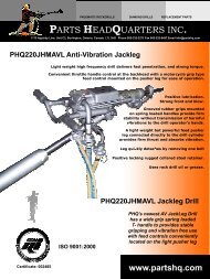
PHQ250JHMAVL Jackleg MK 1 Parts and Repair Manual PDF
PHQ250JHMAVL Jackleg MK 1 Parts and Repair Manual PDF
PHQ250JHMAVL Jackleg MK 1 Parts and Repair Manual PDF
You also want an ePaper? Increase the reach of your titles
YUMPU automatically turns print PDFs into web optimized ePapers that Google loves.
94. Place the end of the anti-vibration spring (AVH665) in the stop on the<br />
backhead. Install four new O-rings (910660216) on the shaft of the antivibration<br />
h<strong>and</strong>le adapter. Lightly grease the shaft <strong>and</strong> slide the anti-vibration<br />
h<strong>and</strong>le adaptor (AVH697) into the backhead. Fit the coil of the anti-vibration<br />
spring (AVH665) into the groove machined around the shaft.<br />
Page 30<br />
95. Place the short end of the spring between the two stops on the control<br />
h<strong>and</strong>le shaft. Put the limit plate (AVH664) complete with a new rubber bumper<br />
(D2105) on the square end of the h<strong>and</strong>le adapter. Tighten grub screw<br />
(AVH661) on the anti-vibration spring where it meets the backhead.<br />
96. Set the anti-vibration operating h<strong>and</strong>le adapter at<br />
the proper angle (maximum 20 degrees off vertical).<br />
Tighten the operating h<strong>and</strong>le nut nyloc (12812UF) on<br />
the outside of limit plate (AV664). Test movement<br />
of the operating h<strong>and</strong>le relative to the backhead. The<br />
h<strong>and</strong>le should oscillate approximately one half inch.<br />
97. Check the control h<strong>and</strong>le friction<br />
ring (164631). Grease control spindle<br />
(B1183 straight fit) <strong>and</strong> push it into<br />
the control body. Fit the twist grip<br />
(C1518) disc washer (149122MT) <strong>and</strong><br />
tighten nut (1218UF) in position.<br />
98. Check rotation of the twist grip. The feel should be firm with the new O-ring but not rigid.<br />
Check that the anti-vibration h<strong>and</strong>le assembly moves in relation to the backhead <strong>and</strong> is not rigid.<br />
99. Lightly oil the retract valve assembly (C151415)<br />
with five new O-rings (164811). Insure the valve <strong>and</strong><br />
valve sleeve are properly assembled. Insert the<br />
assembly into the bore of the adaptor. Fit the two<br />
springs (D1424) (D1425) into the bore of the h<strong>and</strong>le<br />
adaptor. Screw plunger plug (112FN502)in position<br />
100. Check the clevis body spindle <strong>and</strong> install three new O-rings<br />
(164231) If a new cone is required assemble with a new spindle. Ensure<br />
the pin in the spindle is aligned with the key way in the clevis body.<br />
Version 200711


