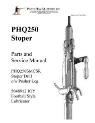
PHQ250JHMAVL Jackleg MK 1 Parts and Repair Manual PDF
PHQ250JHMAVL Jackleg MK 1 Parts and Repair Manual PDF
PHQ250JHMAVL Jackleg MK 1 Parts and Repair Manual PDF

Create successful ePaper yourself
Turn your PDF publications into a flip-book with our unique Google optimized e-Paper software.
Page 20<br />
Removal of Ratchet Ring, Rifle Bar <strong>and</strong> Valve Chest<br />
48. Using piston removal tool (SECP1)<br />
push the piston (B233) back until it<br />
touches the valve chest (A745).<br />
Hammer gently on the tool pushing<br />
ratchet ring (B1170) until it protrudes<br />
about one inch out of the cylinder bore.<br />
49. Remove the valve box locating pin<br />
(S2128) from the groove in the cylinder<br />
using needle nose pliers.<br />
50. Remove the ratchet ring (B1170). Examine the teeth<br />
on the inner diameter of the ring for chipping or wear. The<br />
ratchet ring is reversible <strong>and</strong> it is advisable to reverse sides<br />
whenever removing the ratchet ring to maximize part life.<br />
51. Remove the rifle bar (B1173B) <strong>and</strong> check the spiral<br />
flutes for wear. Set the rifle bar complete with ratchet<br />
pawls aside to examine in detail later. Reversible pawls<br />
can safely be turned to the un-used side to get more life.<br />
52. Using the piston removal tool push or hammer gently<br />
on the face of the drill piston to push the valve chest<br />
assembly out of the cylinder until it drops in you h<strong>and</strong>.<br />
Continue pushing on the piston (B2334) until it emerges<br />
from the drill cylinder <strong>and</strong> catch it in your h<strong>and</strong>. Examine<br />
the striking face of the piston <strong>and</strong> flutes for signs of wear.<br />
If the striking face is chipped the piston must be replaced.<br />
Valve Chest Disassembly<br />
53. Valve chest disassembly must be done using the<br />
proper valve punch T206. Hold the valve chest box in<br />
the palm of one h<strong>and</strong>. Place with the small end of the<br />
valve plug (A744) facing up. Fit the punch in the bore of<br />
the plug. Strike the punch with a brass hammer until the<br />
valve box (A745) separates from the valve plug (A744).<br />
H<strong>and</strong>le the precision ground parts of the valve with care.<br />
Version 200711