BAYONET CONNECTIONS VACUUM INSULATED CRYOGENIC ...
BAYONET CONNECTIONS VACUUM INSULATED CRYOGENIC ...
BAYONET CONNECTIONS VACUUM INSULATED CRYOGENIC ...

You also want an ePaper? Increase the reach of your titles
YUMPU automatically turns print PDFs into web optimized ePapers that Google loves.
<strong>BAYONET</strong> <strong>CONNECTIONS</strong><br />
TM<br />
<strong>VACUUM</strong> <strong>INSULATED</strong><br />
<strong>CRYOGENIC</strong><br />
<strong>CONNECTIONS</strong><br />
Features<br />
Technical Data<br />
Operating Ranges<br />
Temperatures – …………-452°F to +200°F;<br />
-269°C to +93°C<br />
Operating Pressures up to 275 PSIG<br />
Tests<br />
External Leakage – ……Mass Spec. to<br />
1 x 10 -9 cc GHe/sec<br />
Service<br />
Argon, Helium, Hydrogen, Nitrogen and Oxygen<br />
Materials<br />
Metal Components– ……304 & 316<br />
Stainless Steel<br />
Soft Goods – ……………Buna N, Graphite,<br />
Silicone or Teflon ®<br />
• Many Bayonet Styles Available<br />
• Commercial Styles & Close Tolerance<br />
Style now Available from Stock<br />
• Constructed of Material that is Suitable<br />
for Cryogenic Service<br />
• Butt Weld and Socket Weld Ends for<br />
Simple Fabrication into your System<br />
• Thermally Efficient with Inner & Outer<br />
Weldment for Vacuum Jacketed Systems<br />
Applications for Vacuum<br />
Jacketed Systems<br />
• New Vacuum Jacketed Piping Systems<br />
• Storage Vessels, Tanks & Dewars<br />
• Transports & Trailers<br />
• Transfer Hose & Fill Systems<br />
• Expansion of Existing Systems &<br />
Modifications to Current Designs<br />
• Complete Line of Vacuum Jacketed<br />
Valves and Filters<br />
• Bayonets Available for LNG Service<br />
• Consult Factory for Special Applications<br />
Options<br />
• Buna N or Silicone O-Ring and/or Graphite<br />
Face Seals (Determined by Application)<br />
• UHP or Standard Configuration<br />
• Electro-Polished and Special<br />
Cleaning Available<br />
• Complete Design, Testing & Qualification<br />
– 34 –
<strong>BAYONET</strong> <strong>CONNECTIONS</strong><br />
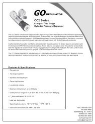
Commercial Bayonets Vacuum Jacketed for Hydrogen & Helium<br />
For Hoses, Tankers and Storage Vessels<br />
C<br />
D<br />
A<br />
B<br />
E<br />
G<br />
MALE AIR FORCE HYDROGEN SERVICE *<br />
Temp. -423°F MAWP 200 PSIG<br />
Size P\N A B C D E Inner Line<br />
1-1/2” PS F-BMAFPS12X 10.6” 9.6” 3.5” 1.9” 7.0” 1-1/2” Sch. 5 Pipe<br />
1-1/2” ODT F-BMAFTS12X 10.6” 9.6” 3.5” 1.5” 7.0” 1-1/2” x .065” Tube<br />
*Shipped with nose seal and o-ring.<br />
H<br />
I<br />
FEMALE AIR FORCE HYDROGEN SERVICE<br />
Temp. -423°F MAWP 200 PSIG<br />
Size P\N F G H I J Inner Line<br />
1-1/2” PS F-BFAFPS12X 10.0” 4.0” 3.5” 1.9” 7.2” 1-1/2” Sch. 5 Pipe<br />
1-1/2” ODT F-BFAFTS12X 10.0” 4.0” 3.5” 1.5” 7.2” 1-1/2” x .065” Tube<br />
1” PS F-BFAFPS08X 10.0” 4.0” 3.5” 1.3” 7.2” 1” Sch. 5 Pipe<br />
1” ODT F-BFAFTS08X 10.0” 4.0” 3.5” 1.0” 7.2” 1” x .065” Tube<br />
J<br />
F<br />
C<br />
D<br />
A<br />
B<br />
E<br />
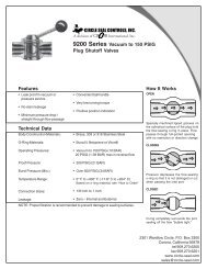
MALE LINDE TYPE HYDROGEN SERVICE*<br />
Temp. -423°F MAWP 200 PSIG<br />
Size P\N A B C D E Inner Line<br />
2” ODT F-BMLTTS16X 8.8” 8.2” 3.5” 2.0” 6.8” 2” x .065” Tube<br />
1-1/2” ODT F-BMLTTS12X 8.8” 8.2” 3.5” 1.5” 6.8” 1-1/2” x .065” Tube<br />
*Shipped with nose seal and energizer. V-Band Clamp required for installation.<br />
H<br />
I<br />
F<br />
J<br />
G<br />
FEMALE LINDE TYPE HYDROGEN SERVICE*<br />
Temp. -423°F MAWP 200 PSIG<br />
Size P\N F G H I J Inner Line<br />
2” PS F-BFLTPS16X 13.0” 8.1” 3.5” 2.38” 8.6” 2” Sch. 5 Pipe<br />
2” ODT F-BFLTTS16X 13.0” 8.1” 3.5” 2.00” 8.6” 2” x .065” Tube<br />
1-1/2” PS F-BFLTPS12X 13.0” 8.1” 3.5” 1.30” 8.6” 1-1/2” Sch. 5 Pipe<br />
1-1/2” ODT F-BFLTTS12X 13.0” 8.1” 3.5” 1.00” 8.6” 1-1/2” x .065” Tube<br />
*Shipped with Kel-F o-ringr. V-Band Clamp required for installation.<br />
A<br />
C<br />
D<br />
B<br />
MALE HELIUM SERVICE*<br />
Temp. -452°F MAWP 175 PSIG<br />
Size P\N A B C D E Inner Line<br />
2” ODT F-BMCYTS16X 17.5” 16.5” 3.5” 2.0” 15.0” 2” x .065” Tube<br />
*Shipped with nose seal and o-ring. V-Band Clamp required for installation.<br />
H<br />
I<br />
E<br />
G<br />
FEMALE HELIUM SERVICE*<br />
Temp. -452°F MAWP 175 PSIG<br />
Size P\N F G H I J Inner Line<br />
2” ODT F-BFCYTS16X 17.38”15.38” 3.5” 2.0” 14.7” 2” x .065” Tube<br />
*V-Band Clamp required for installation.<br />
Dimensions are shown for reference only.<br />
F<br />
J<br />
V-BAND CLAMP<br />
Model<br />
P\N<br />
Linde Type w/Handwheel F-1575<br />
Helium Service w/Handwheel F1585<br />
Helium Service<br />
F1600<br />
– 35 –
<strong>BAYONET</strong> <strong>CONNECTIONS</strong><br />
Commercial Bayonets – Assembly Kits & Options<br />
AIR FORCE TYPE <strong>BAYONET</strong>S *<br />
Kit:<br />
Optional:<br />
P/N F-BPAFxxxx K<br />
Description Material Letter<br />
O-Ring Buna N O<br />
Nose Seal TFE N<br />
Dust Cap Aluminum D<br />
Pressure Cap, Female Stainless Steel S<br />
*The Air Force Type Bayonet is a threaded connection which uses a Teflon ® nose seal<br />
and Buna N O-ring on the male Bayonet. An assembly kit is required for each pair.<br />
Spare Assembly Kits<br />
Type<br />
Part Number<br />
Air Force F-B P AFxxxx K<br />
Linde<br />
F-B P LTxxxx K<br />
Helium F-B P CYxxxx K<br />
Sample Kit Number:<br />
F–B P CYxxxx K<br />
LINDE TYPE <strong>BAYONET</strong>*<br />
P/N F-BPLTxxxx K<br />
Description Material Letter<br />
Kit:<br />
O-Ring PCTFE O<br />
Energizer Stainless Steel E<br />
Nose Seal TFE N<br />
Optional:<br />
Dust Cap Aluminum D<br />
Pressure Cap, Female Stainless Steel S<br />
*The Linde Type Bayonet is a V-band connection which uses a Teflon ® nose seal and<br />
an energizer on the male Bayonet and a Kel-F O-ring on the female Bayonet. An<br />
assembly kit is required for each pair and a V-Band Clamp is required for installation.<br />
HELIUM SERVICE <strong>BAYONET</strong>*<br />
P/N F-BPCYxxxx K<br />
Description Material Letter<br />
Kit:<br />
O-Ring Buna N O<br />
Nose Seal TFE N<br />
Optional:<br />
Dust Cap Aluminum D<br />
Pressure Cap, Female Stainless Steel S<br />
*The Helium Bayonet is a V-band connection which uses a Teflon ® nose seal and Buna<br />
N O-ring on the male Bayonet. An assembly kit is required for each pair and a V-Band<br />
Clamp is required for installation.<br />
When ordering parts for male and female<br />
Bayonets change the “P” in the Kit<br />
Number above to the identification letter<br />
for the connection type shown below:<br />
P = Pair<br />
M = Male<br />
F = Female<br />
To order Optional or Kit Items change the<br />
“K” at the end of the Kit Number above to<br />
the identification letter for the kit<br />
description as shown below:<br />
O = O-Ring<br />
N = Nose Seal<br />
E = Energizer for Linde Type<br />
Nose Seal<br />
K = Complete Assembly Kits as<br />
described above<br />
D = Aluminum Dust Cap<br />
S = Stainless Steel Pressure Cap<br />
– 36 –
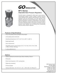
Close Tolerance Bayonets, Dual Seal<br />
For Fixed Vacuum Jacketed Piping Systems<br />
Specify Service: Standard, Oxygen or Hydrogen<br />
<strong>BAYONET</strong> <strong>CONNECTIONS</strong><br />
MALE CLOSE TOLERANCE*<br />
Size* P\N A B C D E F G ∆Q<br />
1/2” x 2” F-BMCTPS04X 0.84” 2.37” 1.56” 8” 12” 6.0” 11” 4.5<br />
1” x 2-1/2” F-BMCTPS08X 1.31” 2.87” 1.75” 10” 14” 7.0” 13” 4.9<br />
1-1/2” x 3” F-BMCTPS12X 1.90” 3.50” 2.44” 9” 13” 7.5” 12” 9.1<br />
2” x 4” F-BMCTPS16X 2.37” 4.50” 2.94” 11” 15” 9.0” 14” 9.7<br />
3” x 5” F-BMCTPS24X 3.50” 5.56” 3.92” 12” 16” 10.0” 15” 10.5<br />
4” x 6” F-BMCTPS32X 4.50” 6.62” 5.35” 16” 20” 11.0” 19” 19.2<br />
6” x 10” F-BMCTPS48X 6.62” 10.75” 8.39” 18” 22” 16.0” 21” 41.0<br />
FEMALE CLOSE TOLERANCE<br />
F<br />
L<br />
B<br />
A<br />
D<br />
ANSI Class 150# Flange Typical<br />
* Male bayonet shipped with all assembly hardware and seals.<br />
K<br />
J<br />
Temp. -423°F MAWP 275 PSIG<br />
Size* P\N H I J K L ∆Q<br />
1/2” x 2” F-BFCTPS04X 0.84” 2.37” 9.00” 11.00” 2.94” 6.7<br />
1” x 2-1/2” F-BFCTPS08X 1.31” 2.87” 11.38” 13.38” 3.88” 7.9<br />
1-1/2” x 3” F-BFCTPS12X 1.90” 3.50” 10.38” 12.38” 4.00” 6.5<br />
2” x 4” F-BFCTPS16X 2.37” 4.50” 11.63” 13.63” 5.00” 6.0<br />
3” x 5” F-BFCTPS24X 3.50” 5.56” 13.75” 15.75” 6.49” 14.7<br />
4” x 6” F-BFCTPS32X 4.50” 6.62” 18.00” 20.00” 7.94” 31.7<br />
6” x 10” F-BFCTPS48X 6.62” 10.75” 19.25” 21.25” 11.94” 37.0<br />
E<br />
G<br />
SI Type Insulation<br />
H<br />
I<br />
C<br />
Temp. -423°F MAWP 275 PSIG<br />
Spare Assembly Kits<br />
Size<br />
Kit Number<br />
1/2” x 2” F-BPCTPS04K<br />
1” x 2-1/2” F-BPCTPS08K<br />
1-1/2” x 3” F-BPCTPS12K<br />
2” x 4” F-BPCTPS16K<br />
3” x 5” F-BPCTPS24K<br />
4” x 6” F-BPCTPS32K<br />
6” x 10” F-BPCTPS48K<br />
Sample Kit Number:<br />
F–BPCTP S 12 K<br />
for 1-1/2” x 3” Bayonet Pair<br />
Required Assembly Parts For Close<br />
Tolerance Bayonets:<br />
To order individual components from<br />
Assembly Kits change the “K” at the end<br />
of the Kit Number above to the I.D. letter<br />
for the component as shown below:<br />
O = O-Ring for Face Seal<br />
N = Nose Seal Only<br />
H = Nuts & Bolts to assemble Male and<br />
Female Bayonet<br />
K = Nose Seal, O-Rings and Nuts & Bolts<br />
Specify Service:<br />
To specify service other than Standard,<br />
change the “S” in the Part Number shown<br />
above to the I.D. letter for the service<br />
shown below:<br />
S = Standard Service includes Argon,<br />
Helium and Liquid Nitrogen<br />
O = Oxygen Service, Consult Factory<br />
H = Hydrogen Service, Consult Factory<br />
The close tolerance Dual Seal Bayonet is a flanged connection using ANSI type flanges. It is assembled with two O-rings, Teflon® nose seal and<br />
stainless steel nuts and bolts. An assembly kit is required for each pair.<br />
Notes for Close Tolerance Bayonets:<br />
SI – Sixteen layers of laminar radiation shielding consisting of alternating layers of glass paper and aluminum foil.<br />
∆Q – Conductive heat leak from ambient to cryogenic temperature. BTU/Hr. @ 77.4°K (LN2).<br />
* – Nominal pipe size. All pipe is Schedule 5 unless noted.<br />
Dimensions shown above are for reference only.<br />
– 37 –