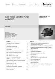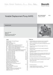
Variable Displacement Pump A10VO RE 92701/11.95 - Group VH A/S
Variable Displacement Pump A10VO RE 92701/11.95 - Group VH A/S
Variable Displacement Pump A10VO RE 92701/11.95 - Group VH A/S

Create successful ePaper yourself
Turn your PDF publications into a flip-book with our unique Google optimized e-Paper software.
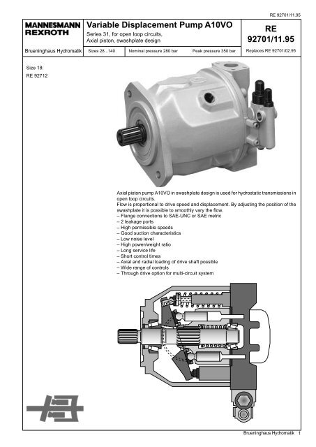
Brueninghaus Hydromatik<br />
<strong>Variable</strong> <strong>Displacement</strong> <strong>Pump</strong> <strong>A10VO</strong><br />
Series 31, for open loop circuits,<br />
Axial piston, swashplate design<br />
Sizes 28...140 Nominal pressure 280 bar Peak pressure 350 bar<br />
<strong>RE</strong> <strong>92701</strong>/<strong>11.95</strong><br />
<strong>RE</strong><br />
<strong>92701</strong>/<strong>11.95</strong><br />
Replaces <strong>RE</strong> <strong>92701</strong>/02.95<br />
Size 18:<br />
<strong>RE</strong> 92712<br />
Axial piston pump <strong>A10VO</strong> in swashplate design is used for hydrostatic transmissions in<br />
open loop circuits.<br />
Flow is proportional to drive speed and displacement. By adjusting the position of the<br />
swashplate it is possible to smoothly vary the flow.<br />
– Flange connections to SAE-UNC or SAE metric<br />
– 2 leakage ports<br />
– High permissible speeds<br />
– Good suction characteristics<br />
– Low noise level<br />
– High power/weight ratio<br />
– Long service life<br />
– Short control times<br />
– Axial and radial loading of drive shaft possible<br />
– Wide range of controls<br />
– Through drive option for multi-circuit system<br />
Brueninghaus Hydromatik<br />
1
<strong>RE</strong> <strong>92701</strong>/<strong>11.95</strong><br />
<strong>Variable</strong> <strong>Displacement</strong> <strong>Pump</strong> <strong>A10VO</strong>, Series 31<br />
Ordering code<br />
Fluid<br />
Mineral oil (no short code)<br />
Axial piston unit<br />
Swashplate design, variable<br />
A10V<br />
Nominal pressure 280 bar, peak pressure 350 bar<br />
Operational mode<br />
<strong>Pump</strong>, open loop circuit<br />
O<br />
Size<br />
<strong>Displacement</strong> V g max<br />
(cm 3 ) 28 45 71* 100 140<br />
Control devices 28 45 71 100 140<br />
2-pos. adjustment, direct control DG DG<br />
Pressure control DR DR<br />
DR G DRG<br />
Remote control<br />
Movable pressure control DRT 1 DRT1<br />
for when required DRT 2 DRT2<br />
i = 18,2 i = 12,4<br />
Pressure and flow control DFR DFR<br />
DFR 1 DFR1<br />
X port closed<br />
Pressure, flow and power control DFLR DFLR<br />
Pressure, flow and summ. power control DFSR<br />
Flow control, pilot pressure-dependent FHD FHD<br />
with pressure control<br />
Electronic flow control FE1 FE1<br />
DFSR<br />
Electronic pressure and flow control DFE1 DFE1<br />
Page 20<br />
Page 22<br />
Page 24<br />
Page 26<br />
Page 26<br />
Page 28<br />
Page 28<br />
Page 30<br />
Page 32<br />
Page 34<br />
Page 36<br />
Page 36<br />
➛<br />
➛<br />
➛<br />
➛<br />
➛<br />
➛<br />
Series<br />
31<br />
Direction of rotation<br />
Viewed on drive shaft clockwise R<br />
anti-clockwise L<br />
= prefered program (with short delivery times)<br />
(type list see page 44)<br />
* With size 71 please note the following when designing:<br />
Pressure port B consists of a multiple high pressure port<br />
SAE 11/4" standard pressure range, 3000 psi, for pressures of up to 250 bar<br />
SAE 1" standard pressure range, 5000 psi, for pressures > 250 bar (see page 14).<br />
For new applications high pressure port SAE 1" must be used.<br />
= available<br />
= in preparation<br />
– = not available<br />
2 Brueninghaus Hydromatik
<strong>RE</strong> <strong>92701</strong>/<strong>11.95</strong><br />
<strong>Variable</strong> <strong>Displacement</strong> <strong>Pump</strong> <strong>A10VO</strong>, Series 31<br />
A10V O / 31 –<br />
➛<br />
➛<br />
➛<br />
➛<br />
➛<br />
➛<br />
Axial piston pump<br />
Operational mode<br />
Size<br />
Adjustment and control devices<br />
Series<br />
Direction of rotation<br />
Seals<br />
NBR (Nitrile rubber to DIN ISO 1629)<br />
P<br />
FPM (Fluoro rubber to DIN ISO 1629)<br />
V<br />
Shaft end 28 45 71 100 140<br />
Splined shaft SAE 7/8" 1" 1 1/4" 1 1/2" 1 3/4" S<br />
Splined shaft SAE (higher through drive torque) 7/8" 1" 1 1/4" – – R<br />
Splined shaft SAE (not suitable for through drive) – 7/8" – 1 1/4" – U<br />
Mounting flange 28 45 71 100 140<br />
SAE 2-hole – C<br />
SAE 4-hole – – – – D<br />
Port for service lines 28 45 71 100 140<br />
Pressure port B SAE at rear, fixing thread UNC 61<br />
Suction port S<br />
}<br />
Pressure port B SAE on opposite sides, 62<br />
}<br />
Suction port S fixing thread UNC<br />
}<br />
Pressure port B SAE at rear, metric fixing thread 11<br />
Suction port S<br />
}<br />
Pressure port B SAE on opposite sides, 12<br />
Suction port S metric fixing thread<br />
Port pos. 61<br />
and 11 only<br />
for version<br />
without<br />
through drive<br />
Through drive<br />
Without through drive<br />
N00<br />
With through drive (port pos. 62, 12) for mounting AKM or ZRP<br />
Mounting flange Shaft/coupling For mounting:<br />
82-2(SAE A) 16-4(SAE A) G2, GC2/GC3-1X K01<br />
82-2(SAE A) 19-4(SAE A-B) A10VSO 18 (shaft S) K52<br />
101-2(SAE B) 22-4(SAE B) <strong>A10VO</strong> 28 (shaft S), G3 K02<br />
101-2(SAE B) 22-4(SAE B) G4 K68<br />
101-2(SAE B) 25-4(SAE B-B) <strong>A10VO</strong> 45 (shaft S), GC4-1X – K04<br />
101-2(SAE B) 32-4(SAE C) GC5-1X – K06<br />
127-2(SAE C) 32-4(SAE C) <strong>A10VO</strong> 71 (shaft S) – – K07<br />
127-2(SAE C) 38-4(SAE C-C) <strong>A10VO</strong> 100 (shaft S), GC6-1X – – – K24<br />
152-4(SAE D) 44-4(SAE D) <strong>A10VO</strong> 140 (shaft S) – – – – K17<br />
Multiple pumps<br />
1. If a second Brueninghaus Hydromatik pump is to be factory-mounted, then both ordering codes are to be<br />
specified, combined with a "+" . Ordering code 1st pump + Ordering code 2nd pump<br />
Ordering example: <strong>A10VO</strong> 100DR/31R-PSC62K07 + <strong>A10VO</strong> 71DR/31R-PSC62N00<br />
2. If a gear pump is to be factory-mounted please contact us (<strong>RE</strong> 90139 in preparation)<br />
Brueninghaus Hydromatik<br />
3
<strong>RE</strong> <strong>92701</strong>/<strong>11.95</strong><br />
<strong>Variable</strong> <strong>Displacement</strong> <strong>Pump</strong> <strong>A10VO</strong>, Series 31<br />
Fluid<br />
Prior to project design, please see our data sheets <strong>RE</strong> 90220<br />
(mineral oil) and <strong>RE</strong> 90221 (ecologically acceptable fluids) for<br />
detailed information on fluids and application conditions.<br />
When using ecologically acceptable fluids attention must be<br />
paid to possible limitations of the technical data. If necessary<br />
please contact us.<br />
Operating viscosity range<br />
For optimum efficiency and service life we recommend that the<br />
operating viscosity (at operating temperature) be selected in the<br />
range<br />
ν opt<br />
= opt. operating viscosity 16...36 mm 2 /s<br />
referred to tank temperature (open loop circuit).<br />
Limits of viscosity range<br />
The following values are valid for extreme operating conditions:<br />
ν min<br />
= 10 mm 2 /s<br />
for short periods at max. leakage oil temperature<br />
of 90° C.<br />
ν max<br />
= 1000 mm 2 /s<br />
for short periods upon cold start.<br />
Temperature range (see selection diagram)<br />
t min<br />
= –25° C<br />
= +90° C<br />
t max<br />
Selection diagram<br />
Notes on the selection of fluid<br />
For correct selection of the fluid it is assumed that the operating<br />
temperature in the tank is known (open loop circuits), in relation<br />
to the ambient temperature.<br />
The fluid should be selected so that, within the operating<br />
temperature range, the operating viscosity lies within the<br />
optimum range (ν opt<br />
), (see shaded section of selection diagram).<br />
We recommend that the higher viscosity grade is selected in<br />
each case.<br />
Example: At an ambient temperature of X° C the operating<br />
temperature in the tank will be 60° C. In the optimum operating<br />
viscosity range (ν opt<br />
; shaded section) this corresponds to<br />
viscosity grade VG 46 or VG 68; VG 68 should be selected.<br />
Important: The leakage oil temperature is influenced by<br />
pressure and speed and is always higher than the tank<br />
temperature. At no point in the system, however, may the<br />
temperature be higher than 90° C.<br />
If it is not possible to comply with the above conditions because<br />
of extreme operating parameters or a high ambient temperature,<br />
please consult us.<br />
Filtration<br />
In order to ensure reliable operation of the axial piston unit, the<br />
operating fluid must be maintained to a cleanliness class of at<br />
least 9 to NAS 1638<br />
6 to SAE<br />
18/15 to ISO/DIS 4406.<br />
This may be achieved, for example, with filter elements<br />
type...D 020...(see <strong>RE</strong> 31278).<br />
This gives the following degree of separation:<br />
1000<br />
600<br />
400<br />
200<br />
- 20° 0° 20° 40° 60° 80° 100°<br />
1000<br />
VG 22<br />
VG 32<br />
VG 68<br />
VG 46<br />
VG 100<br />
β 20<br />
≥ 100<br />
2<br />
Viskosität υ (mm / s)<br />
Viscosity<br />
100<br />
80<br />
60<br />
40<br />
20<br />
15<br />
10<br />
- 25° - 10° 10°<br />
10<br />
30° 50° 70° 90° Temperature<br />
t min = - 25° C Druckflüssigkeitstemperaturbereich<br />
Fluid temperature range<br />
36<br />
υ opt<br />
16<br />
t (° C)<br />
t max = + 90° C<br />
4 Brueninghaus Hydromatik
<strong>RE</strong> <strong>92701</strong>/<strong>11.95</strong><br />
<strong>Variable</strong> <strong>Displacement</strong> <strong>Pump</strong> <strong>A10VO</strong>, Series 31<br />
Technical data<br />
Inlet operating pressure range<br />
Absolute pressure at port S (A)<br />
p abs min<br />
........................................................................... 0,8 bar<br />
p abs max<br />
........................................................................... 30 bar<br />
Determination of inlet pressure p abs<br />
at suction port S, or<br />
reduction in flow for increasing speed.<br />
Outlet operating pressure range<br />
Pressure at port B<br />
Nominal pressure p N<br />
.................................................. 280 bar<br />
Peak pressure p max<br />
..................................................... 350 bar<br />
(Pressure data to DIN 24312)<br />
Applications with intermittent operating pressures of up to 315<br />
bar at 10% duty cycle are permitted.<br />
Case drain pressure<br />
Maximum pressure of leakage fluid (at ports L, L 1<br />
):maximum 0,5<br />
bar higher than input pressure at port S, but not exceeding 2 bar<br />
absolute.<br />
Speed n/ n max<br />
1,2<br />
1,1<br />
1,0<br />
0,9<br />
0,7<br />
0,8<br />
1,6<br />
1,4<br />
1,2<br />
1,0<br />
0,9<br />
Direction of flow<br />
S to B<br />
<strong>Displacement</strong> V g<br />
/V gmax<br />
0,9<br />
1,0<br />
0,8<br />
Inlet pressure p abs<br />
[bar]<br />
Tabulated data (theoretical values, without considering η mh<br />
and η v<br />
; approximate values)<br />
Size 28 45 71 100 140<br />
<strong>Displacement</strong> V g max<br />
cm 3 28 45 71 100 140<br />
Max. speed 1 ) at V g max<br />
n o max<br />
rpm 3000 2600 2200 2000 1800<br />
Max. flow at n o max<br />
Q o max<br />
L/min 84 117 156 200 252<br />
at n E<br />
= 1500 rpm L/min 42 68 107 150 210<br />
Max. power (∆p = 280 bar) at n o max<br />
P o max<br />
kW 39 55 73 93 118<br />
at n E<br />
= 1500 rpm kW 20 32 50 70 98<br />
Max. torque (∆p = 280 bar) at V g max<br />
T max<br />
Nm 125 200 316 445 623<br />
Torque (∆p = 100 bar) bei V g max<br />
T Nm 45 72 113 159 223<br />
Moment of inertia at drive axis J kgm 2 0,0017 0,0033 0,0083 0,0167 0,0242<br />
Filling capacity L 0,7 1,0 1,6 2,2 3,0<br />
Weight (without fluid) m kg 15 21 33 45 60<br />
Permissible loading of drive shaft:<br />
Max. axial force F ax max<br />
N 1000 1500 2400 4000 4800<br />
Max. radial force 2 ) F q max<br />
N 1200 1500 1900 2300 2800<br />
1<br />
) Values shown are valid for an absolute pressure of 1 bar at<br />
suction port S.<br />
If the flow is reduced or if the inlet pressure is increased the<br />
speed may be increased according to the diagram.<br />
2<br />
) Please consult us for higher radial forces.<br />
Determination of size<br />
Forces<br />
± Fax<br />
Fq<br />
X/2 X/2<br />
X<br />
V g<br />
• n • η v<br />
Flow Q =<br />
1000<br />
[L/min]<br />
Drive torque T =<br />
1,59 • V g<br />
• ∆ p<br />
100 • η mh<br />
[Nm]<br />
600 • η t<br />
60000 9549<br />
η t<br />
= total efficiency (η t<br />
= η • v<br />
η mh<br />
)<br />
V g<br />
= geometric displacement [cm 3 ] per rev.<br />
∆ p = differential pressure [bar]<br />
n = speed [rpm]<br />
η v<br />
= volumetric efficiency<br />
η mh<br />
= mechanical-hydraulic efficiency<br />
2π • T • n T • n Q • ∆ p<br />
Drive power P = = = [kW]<br />
Brueninghaus Hydromatik<br />
5
<strong>RE</strong> <strong>92701</strong>/<strong>11.95</strong><br />
<strong>Variable</strong> <strong>Displacement</strong> <strong>Pump</strong> <strong>A10VO</strong>, Series 31<br />
Installation notes<br />
Optional installation position. The pump housing must be filled<br />
with fluid during commissioning and remain full when operating.<br />
In order to attain the lowest noise level, all connections (suction,<br />
pressure, case drain ports) must be linked by flexible couplings<br />
to tank.<br />
Avoid placing a check valve in the case drain line.<br />
This may, however, be permissible in individual cases, after<br />
consultation with us.<br />
1. Vertical installation (shaft end upwards)<br />
The following installation conditions must be taken into<br />
account:<br />
1.1. Arrangement in tank<br />
Before installation fill pump housing, keeping it in a horizontal<br />
position.<br />
a) If the minimum fluid level is equal to or above the pump<br />
mounting surface leave ports “L”, "L 1<br />
" and “S” open (see<br />
Fig.1).<br />
b) If the minimum fluid level is below the pump mounting<br />
surface pipe port “L 1<br />
”, and possibly “S” according to Fig. 2.<br />
Close port "L" with respect to conditions in 1.2.1.<br />
1.2. Arrangement outside tank<br />
Before installation fill pump housing, keeping it in a horizontal<br />
position. For mounting above tank see Fig. 2.<br />
Limiting condition:<br />
1.2.1. Minimum pump inlet pressure p inlet min<br />
= 0,8 bar under<br />
static and dynamic loading.<br />
Note: Avoid mounting above tank wherever possible in order<br />
to attain a low noise level.<br />
pressure loss, but may not be greater than h max<br />
= 800 mm<br />
(immersion depth h t min<br />
= 200 mm).<br />
h t min<br />
h max<br />
L 1<br />
S<br />
L 1<br />
S<br />
Fluid<br />
The permissible suction height h is a result of the overall<br />
Total pressure loss ∆p total<br />
= ∆p 1<br />
+ ∆p 2<br />
+ ∆p 3<br />
≤ (1 – p inlet min<br />
) = 0,2 bar<br />
∆p 1<br />
: Pressure loss in pipe due to accelerating column of fluid<br />
ρ • l • dv<br />
∆p 1<br />
=<br />
• 10 –5 (bar)<br />
dt ρ = density (kg/m 3 )<br />
l = pipe length (m)<br />
dv/dt = change in rate of suction<br />
(m/s 2 )<br />
∆p 2<br />
: Pressure loss due to static head<br />
∆p 2<br />
= h • ρ • g • 10 –5 (bar) h = height (m)<br />
ρ = density (kg/m 3 )<br />
g = acc. due to gravity. =<br />
9,81 m/s 2<br />
∆p 3<br />
: Line losses (elbows etc.)<br />
L<br />
Fig. 1<br />
Fluid<br />
Fig. 2<br />
L<br />
2. Horizontal installation<br />
The pump must be installed so that either "L" or "L 1<br />
" is at the<br />
top.<br />
2.1. Arrangement in tank<br />
a) If the minimum fluid level is above the top of the pump<br />
leave ports "L", "L 1<br />
" and “S” open (see Fig. 3)<br />
b) If the minimum fluid level is equal to or below the top of the<br />
pump pipe ports "L", "L 1<br />
" and possiby "S" according to Fig. 4.<br />
Conditions according to 1.2.1.<br />
2.2. Arrangement outside tank<br />
Fig. 3<br />
Fill pump housing before commissioning.<br />
Pipe port "S" and the higher of the two case drain ports "L"<br />
and "L 1<br />
".<br />
a) For mounting above tank see Fig. 4.<br />
Conditions according to 1.2.1.<br />
b) Position below tank<br />
L<br />
L 1<br />
L 1<br />
L<br />
Fluid<br />
Pipe ports "L" and “S” according to Fig. 5.<br />
Fluid<br />
Fluid<br />
L<br />
p Inlet min<br />
p Inlet min<br />
h max<br />
S<br />
p Inlet min<br />
Fig. 4<br />
L 1<br />
S<br />
Fig. 5<br />
S<br />
6 Brueninghaus Hydromatik
<strong>RE</strong> <strong>92701</strong>/<strong>11.95</strong><br />
<strong>Variable</strong> <strong>Displacement</strong> <strong>Pump</strong> <strong>A10VO</strong>, Series 31<br />
Characteristics for pump with pressure control DR<br />
Noise characteristic<br />
Measured in an anechoic chamber<br />
Distance from microphone to pump = 1 m<br />
Measurement tolerance: ± 2 dB (A)<br />
(Fluid: hydraulic oil ISO VG 46 DIN 51519, t = 50° C)<br />
Size 28 Size 100<br />
Noise level L A<br />
[dB(A)]<br />
74<br />
72<br />
70<br />
68<br />
66<br />
64<br />
62<br />
60<br />
58<br />
56<br />
0<br />
Size 45<br />
76<br />
Noise level L A<br />
[dB(A)]<br />
Size 71<br />
Noise level L A<br />
[dB(A)]<br />
74<br />
72<br />
70<br />
68<br />
66<br />
64<br />
62<br />
60<br />
58<br />
0<br />
80<br />
78<br />
76<br />
74<br />
72<br />
70<br />
68<br />
66<br />
64<br />
62<br />
60<br />
58<br />
0<br />
50<br />
50<br />
50<br />
n n= = 3000 min rpm -1<br />
100<br />
n n= = 1500 min rpm -1<br />
150<br />
n n= = 2200 min rpm -1<br />
n n= = 1500 min rpm<br />
-1<br />
200<br />
Operating pressure p [bar]<br />
n n= = 2600 min rpm -1<br />
n n= = 1500 min rpm -1<br />
250<br />
100 150 200 250<br />
Operating pressure p [bar]<br />
100 150 200 250<br />
Operating pressure p [bar]<br />
280<br />
280<br />
Q max<br />
Q min<br />
Q max<br />
Q min<br />
280<br />
Q max<br />
Q min<br />
Q max<br />
Q min<br />
Q max<br />
Q min<br />
Q max<br />
Q min<br />
Noise level L A<br />
[dB(A)]<br />
82<br />
80<br />
78<br />
76<br />
74<br />
72<br />
70<br />
68<br />
66<br />
64<br />
62<br />
60<br />
0<br />
Size 140<br />
Noise level L A<br />
[dB(A)]<br />
84<br />
82<br />
80<br />
78<br />
76<br />
74<br />
72<br />
70<br />
68<br />
66<br />
64<br />
62<br />
60<br />
0<br />
50<br />
50<br />
n n= = 2000 min rpm -1<br />
n n= = 1500 min rpm -1<br />
100 150 200 250<br />
Operating pressure p [bar]<br />
280<br />
Q max<br />
Q min<br />
Q max<br />
Q min<br />
Q max<br />
Q min<br />
Q max<br />
n n= = 1800 min rpm -1 Q min<br />
100 150<br />
n n= = 1500 1500 min rpm -1<br />
200 250 280<br />
Operating pressure p [bar]<br />
Brueninghaus Hydromatik<br />
7
<strong>RE</strong> <strong>92701</strong>/<strong>11.95</strong><br />
<strong>Variable</strong> <strong>Displacement</strong> <strong>Pump</strong> <strong>A10VO</strong>, Series 31<br />
Drive power and flow<br />
(Fluid: hydraulic oil ISO VG 46 DIN 51519, t = 50° C)<br />
Size 28<br />
– – – – n = 1500 rpm<br />
n = 3000 rpm<br />
90<br />
80<br />
40<br />
Flow Q [L/min]<br />
60<br />
40<br />
20<br />
Q<br />
P Qmin<br />
P Qmax<br />
30<br />
20<br />
10<br />
0<br />
Drive power P [kW]<br />
0<br />
50<br />
100<br />
150 200 250<br />
Operating pressure p [bar]<br />
280<br />
Size 45<br />
– – – – n = 1500 rpm<br />
n = 2600 rpm<br />
Flow Q [L/min]<br />
120<br />
100<br />
80<br />
60<br />
40<br />
20<br />
Q<br />
P Qmin<br />
P Qmax<br />
60<br />
50<br />
40<br />
30<br />
20<br />
10<br />
Drive power P [kW]<br />
0<br />
50<br />
100<br />
150 200 250<br />
Operating pressure p [bar]<br />
280<br />
0<br />
Size 71<br />
– – – – n = 1500 rpm<br />
n = 2200 rpm<br />
160<br />
140<br />
120<br />
Q<br />
80<br />
70<br />
60<br />
Flow Q [L/min]<br />
100<br />
80<br />
60<br />
40<br />
20<br />
P Qmin<br />
P Qmax<br />
50<br />
40<br />
30<br />
20<br />
10<br />
Drive power P [kW]<br />
0<br />
0<br />
50<br />
100<br />
150<br />
200<br />
250<br />
280<br />
Operating pressure p [bar]<br />
8 Brueninghaus Hydromatik
<strong>RE</strong> <strong>92701</strong>/<strong>11.95</strong><br />
<strong>Variable</strong> <strong>Displacement</strong> <strong>Pump</strong> <strong>A10VO</strong>, Series 31<br />
Drive power and flow<br />
(Fluid: hydraulic oil ISO VG 46 DIN 51519, t = 50° C)<br />
Size 100<br />
– – – – n = 1500 rpm<br />
n = 2000 rpm<br />
200<br />
180<br />
160<br />
Q<br />
100<br />
90<br />
80<br />
Flow Q [L/min]<br />
140<br />
120<br />
100<br />
80<br />
70<br />
60<br />
50<br />
40<br />
P Qmax<br />
P Qmin<br />
10<br />
Drive power P [kW]<br />
60<br />
30<br />
40<br />
20<br />
20<br />
0<br />
0<br />
50<br />
100<br />
150<br />
200<br />
250<br />
280<br />
Operating pressure p [bar]<br />
Size 140<br />
– – – – n = 1500 rpm<br />
n = 1800 rpm<br />
260<br />
240<br />
220<br />
Q<br />
130<br />
120<br />
110<br />
200<br />
100<br />
Flow Q [L/min]<br />
180<br />
160<br />
140<br />
120<br />
P Qmax<br />
90<br />
80<br />
70<br />
60<br />
Drive power P [kW]<br />
100<br />
50<br />
80<br />
40<br />
Total efficiency:<br />
Q • p<br />
η t<br />
=<br />
P Q max<br />
• 600<br />
60<br />
40<br />
20<br />
P Qmin<br />
30<br />
20<br />
10<br />
Volumetric efficiency:<br />
Q<br />
η v<br />
=<br />
Q theor.<br />
0<br />
50<br />
100<br />
150 200 250<br />
Operating pressure p [bar]<br />
280<br />
0<br />
Brueninghaus Hydromatik<br />
9
<strong>RE</strong> <strong>92701</strong>/<strong>11.95</strong><br />
<strong>Variable</strong> <strong>Displacement</strong> <strong>Pump</strong> <strong>A10VO</strong>, Series 31<br />
Before finalising your design please request a certified drawing.<br />
Subject to revision.<br />
Unit dimensions, size 28<br />
Service ports at rear, no through drive;<br />
Model 61 N00<br />
without considering adjustment<br />
Flange 101-2<br />
(SAE B; 2-hole)<br />
SAE J744 OCT 83<br />
View Z<br />
deep<br />
deep<br />
Shaft S<br />
Shaft<br />
Shaft R<br />
Shaft<br />
30 o pressure angle,<br />
13 splines,<br />
16/32 pitch<br />
30 o pressure angle,<br />
13 splines,<br />
16/32 pitch<br />
useful spline length<br />
Ports<br />
B Pressure port SAE 3/4" (standard pressure series)<br />
S Suction port SAE 1 1/4" (standard pressure series)<br />
L Case drain port 3/4-16 UNF-2B<br />
L 1<br />
Case drain port 3/4-16 UNF-2B (sealed in factory)<br />
10 Brueninghaus Hydromatik
<strong>RE</strong> <strong>92701</strong>/<strong>11.95</strong><br />
<strong>Variable</strong> <strong>Displacement</strong> <strong>Pump</strong> <strong>A10VO</strong>, Series 31<br />
Before finalising your design please request a certified drawing.<br />
Subject to revision.<br />
Unit dimensions, size 28<br />
Service ports on side, no through drive;<br />
Model 62 N00<br />
View W<br />
View V<br />
deep<br />
deep<br />
Service ports at rear, no through drive;<br />
Model 11 N00<br />
View Z<br />
deep<br />
Ports<br />
L Case drain port M18x1,5<br />
Service ports on side, no through drive;<br />
Model 12 N00<br />
deep<br />
View W<br />
deep<br />
View V<br />
deep<br />
Ports<br />
L Case drain port M18x1,5<br />
Brueninghaus Hydromatik<br />
11
<strong>RE</strong> <strong>92701</strong>/<strong>11.95</strong><br />
<strong>Variable</strong> <strong>Displacement</strong> <strong>Pump</strong> <strong>A10VO</strong>, Series 31<br />
Before finalising your design please request a certified drawing.<br />
Subject to revision.<br />
Unit dimensions, size 45<br />
Service ports at rear, no through drive;<br />
Model 61 N00<br />
without considering adjustment<br />
Flange 101-2<br />
(SAE B; 2-hole)<br />
SAE J744 OCT 83<br />
View Z<br />
deep<br />
deep<br />
Shaft S<br />
Shaft R<br />
Shaft U<br />
Shaft Shaft Shaft<br />
useful<br />
spline length<br />
30 o pressure angle,<br />
15 splines,<br />
16/32 pitch<br />
30 o pressure angle,<br />
15 splines,<br />
16/32 pitch<br />
30 o pressure angle,<br />
13 splines,<br />
16/32 pitch<br />
Ports<br />
B Pressure port SAE 1" (standard pressure series)<br />
S Suction port SAE 1 1/2" (standard pressure series)<br />
L Case drain port 7/8-14 UNF-2B<br />
Case drain port 7/8-14 UNF-2B(sealed in factory)<br />
L 1<br />
12 Brueninghaus Hydromatik
<strong>RE</strong> <strong>92701</strong>/<strong>11.95</strong><br />
<strong>Variable</strong> <strong>Displacement</strong> <strong>Pump</strong> <strong>A10VO</strong>, Series 31<br />
Before finalising your design please request a certified drawing.<br />
Subject to revision.<br />
Unit dimensions, size 45<br />
Service ports on sides, no through drive;<br />
Model 62 N00<br />
View W<br />
View V<br />
deep<br />
deep<br />
Service ports at rear, no through drive;<br />
Model 11 N00<br />
View Z<br />
deep<br />
Ports<br />
L Case drain port M22x1,5<br />
Service ports on sides, no through drive;<br />
Model 12 N00<br />
deep<br />
View W View V<br />
deep<br />
deep<br />
Ports<br />
L Case drain port M22x1,5<br />
Brueninghaus Hydromatik<br />
13
<strong>RE</strong> <strong>92701</strong>/<strong>11.95</strong><br />
<strong>Variable</strong> <strong>Displacement</strong> <strong>Pump</strong> <strong>A10VO</strong>, Series 31<br />
Before finalising your design please request a certified drawing.<br />
Subject to revision.<br />
Unit dimensions, size 71<br />
Service ports at rear, no through drive;<br />
Model 61 N00<br />
without considering adjustment<br />
Flange 127-2<br />
(SAE C; 2-hole)<br />
SAE J744 OCT 83<br />
Fixing thread<br />
3/8-16UNC-2B; 18 deep<br />
for SAE 1"<br />
View Z<br />
Fixing thread<br />
7/16-14UNC-2B;<br />
24 deep<br />
for SAE 1 1/4"<br />
deep<br />
Shaft S<br />
Shaft<br />
Shaft R<br />
Shaft<br />
30 o pressure angle,<br />
14 splines,<br />
12/24 pitch<br />
30 o pressure angle,<br />
14 splines,<br />
12/24 pitch<br />
useful spline length<br />
Please note the following when designing:<br />
For pressure port B there are two SAE mounting positions, set at 90 o to each other.<br />
SAE 11/4" standard pressure series, 3000 psi, for pressures of up to 250 bar or<br />
SAE 1" standard pressure series, 5000 psi, for pressures above 250 bar<br />
For operating pressures greater than 250 bar or with new applications pressure flange SAE 1" must be used.<br />
Ports<br />
B Pressure port SAE 1" (standard pressure series) fixing thread optionally to SAE 1" or SAE 1 1/4"<br />
S Suction port SAE 2" (standard pressure series)<br />
L Case drain port 7/8-14 UNF-2B<br />
L 1<br />
Case drain port 7/8-14 UNF-2B (sealed in factory)<br />
14 Brueninghaus Hydromatik
<strong>RE</strong> <strong>92701</strong>/<strong>11.95</strong><br />
<strong>Variable</strong> <strong>Displacement</strong> <strong>Pump</strong> <strong>A10VO</strong>, Series 31<br />
Arbeitsanschlüsse Service ports on sides, seitlich, no ohne through Durchtrieb; drive; Ausführung 62 N00 / 12 N00<br />
ohne Berücksichtigung der Verstellung<br />
Model 62 N00<br />
View W<br />
deep<br />
View V<br />
Fixing thread<br />
3/8-16UNC-2B; 18 deep<br />
for SAE 1"<br />
Service ports at rear, no through drive;<br />
Model 11 N00<br />
Fixing thread<br />
M10; 17 deep<br />
for SAE 1"<br />
View Z<br />
Fixing thread<br />
7/16-14UNC-2B; 24 deep<br />
for SAE 1 1/4"<br />
Fixing thread<br />
M10; 17 deep<br />
for SAE 1 1/4"<br />
Ports<br />
L Case drain port M22x1,5<br />
Service ports on sides, no through drive;<br />
Model 12 N00<br />
View W<br />
deep<br />
deep<br />
View V<br />
Fixing thread<br />
M10; 17 deep<br />
for SAE 1"<br />
Ports<br />
L Case drain port M22x1,5<br />
Fixing thread<br />
M10; 17 deep<br />
for SAE 1 1/4"<br />
Brueninghaus Hydromatik<br />
15
<strong>RE</strong> <strong>92701</strong>/<strong>11.95</strong><br />
<strong>Variable</strong> <strong>Displacement</strong> <strong>Pump</strong> <strong>A10VO</strong>, Series 31<br />
Before finalising your design please request a certified drawing.<br />
Subject to revision.<br />
Unit dimensions, size 100<br />
Service ports at rear, no through drive;<br />
Model 61 N00<br />
without considering adjustment<br />
Flange 127-2<br />
(SAE C; 2-hole)<br />
SAE J744 OCT 83 View Z<br />
deep<br />
deep<br />
Shaft S<br />
Shaft<br />
Shaft U<br />
Shaft<br />
30 o pressure angle,<br />
17 splines,<br />
12/24 pitch<br />
30 o pressure angle,<br />
14 splines,<br />
12/24 pitch<br />
Ports<br />
B Pressure port SAE 1 1/4" (high pressure series)<br />
S Suction port SAE 2 1/2" (standard pressure series)<br />
L Case drain port 1 1/16-12 UN-2B<br />
L 1<br />
Case drain port 1 1/16-12 UN-2B (sealed in factory)<br />
16 Brueninghaus Hydromatik
<strong>RE</strong> <strong>92701</strong>/<strong>11.95</strong><br />
<strong>Variable</strong> <strong>Displacement</strong> <strong>Pump</strong> <strong>A10VO</strong>, Series 31<br />
Before finalising your design please request a certified drawing.<br />
Subject to revision.<br />
Unit dimensions, size 100<br />
Service ports on sides, no through drive;<br />
Model 62 N00<br />
View W View V<br />
deep<br />
deep<br />
Service ports at rear, no through drive;<br />
Model 11 N00<br />
View Z<br />
deep<br />
Ports<br />
L Case drain oil M27x2<br />
Service ports on sides, no through drive;<br />
Model 12 N00<br />
deep<br />
View W View V<br />
deep<br />
deep<br />
Port<br />
L Case drain port M27x2<br />
Brueninghaus Hydromatik<br />
17
<strong>RE</strong> <strong>92701</strong>/<strong>11.95</strong><br />
<strong>Variable</strong> <strong>Displacement</strong> <strong>Pump</strong> <strong>A10VO</strong>, Series 31<br />
Unit dimensions, size 140<br />
Service ports at rear, no through drive;<br />
Model 61 N00<br />
without considering adjustment<br />
Flange 152-4<br />
(SAE D; 4-hole)<br />
SAE J744 OCT 83<br />
View Z<br />
deep<br />
deep<br />
Shaft S<br />
Shaft<br />
30 o pressure angle,<br />
13 splines,<br />
8/16 pitch<br />
Ports<br />
B (A) Pressure port SAE 1 1/4" (high pressure series)<br />
S Suction port SAE 2 1/2" (standard pressure series)<br />
L Case drain port 1 1/16-12 UN-2B<br />
L 1<br />
Case drain port 1 1/16-12 UN-2B (sealed in factory)<br />
18 Brueninghaus Hydromatik
<strong>RE</strong> <strong>92701</strong>/<strong>11.95</strong><br />
<strong>Variable</strong> <strong>Displacement</strong> <strong>Pump</strong> <strong>A10VO</strong>, Series 31<br />
Unit dimensions, size 140<br />
Service ports on sides, no through drive;<br />
Model 62 N00<br />
View W View V<br />
deep<br />
deep<br />
Service ports at rear, no through drive;<br />
Model 11 N00<br />
View Z<br />
deep<br />
Ports<br />
L Case drain port M27x2<br />
deep<br />
Service ports on sides, no through drive;<br />
Model 12 N00<br />
View W<br />
deep<br />
View V<br />
deep<br />
Ports<br />
L Case drain port M27x2<br />
Brueninghaus Hydromatik<br />
19
<strong>RE</strong> <strong>92701</strong>/<strong>11.95</strong><br />
<strong>Variable</strong> <strong>Displacement</strong> <strong>Pump</strong> <strong>A10VO</strong>, Series 31<br />
DG 2-position adjustment, direct control<br />
The pump can be set to a minimum swivel angle by connecting<br />
an external switching pressure to port X.<br />
This will supply the piston direct with oil, a minimum setting<br />
pressure of p St<br />
≥ 30 bar being required.<br />
The pump can only be switched between V gmax<br />
or V gmin<br />
.<br />
Static characteristic<br />
280 max<br />
Switching pressure [bar]<br />
30<br />
10<br />
0<br />
Vgmin<br />
Vgmax<br />
<strong>Displacement</strong><br />
Switching pressure in X = 0 bar = V gmax<br />
Ports<br />
B<br />
Pressure port<br />
S<br />
Suction port<br />
L, L1 Case drain ports (L1 sealed)<br />
X<br />
Pilot pressure port (sealed)<br />
Switching pressure in X ≥ 30 bar = V gmin<br />
Control data<br />
Min. switching pressure<br />
Max. perm. switching pressure<br />
30 bar<br />
280 bar<br />
Unit dimensions<br />
Size A 1<br />
A 2<br />
A 3<br />
A 4<br />
A 5<br />
A 6<br />
A 7<br />
A 8<br />
X (sealed)<br />
}<br />
28 193,5 190 0 55 158 100 103,5 3 R 1/4"<br />
45 212,5 209 3 63,5 173 110 113,5 3 R 1/4"<br />
71 246,5 242,5 3 73,5 201 123,5 127,5 3 R 1/4"<br />
100 311,5 307,5 3 81 268 128,5 132,5 3 R 1/4"<br />
140 338 334 3 94 268 150,5 155 3 R 1/4"<br />
for all models<br />
20 Brueninghaus Hydromatik
<strong>RE</strong> <strong>92701</strong>/<strong>11.95</strong><br />
<strong>Variable</strong> <strong>Displacement</strong> <strong>Pump</strong> <strong>A10VO</strong>, Series 31<br />
Before finalising your design please request a certified drawing.<br />
Subject to revision.<br />
Unit dimensions DG<br />
Service ports at rear; Models 61N00 and 11N00<br />
Sizes 28 to 100<br />
View Z<br />
Mounting for clockwise<br />
direction of rotation<br />
Mounting for anticlockwise<br />
direction of<br />
rotation<br />
Size 140<br />
View Z<br />
Unit dimensions DG<br />
Service ports on sides; Models 62 and 12<br />
Sizes 28 to 100<br />
Mounting for clockwise<br />
direction of rotation<br />
Mounting for anticlockwise<br />
direction of<br />
rotation<br />
Size 140<br />
Brueninghaus Hydromatik<br />
21
<strong>RE</strong> <strong>92701</strong>/<strong>11.95</strong><br />
<strong>Variable</strong> <strong>Displacement</strong> <strong>Pump</strong> <strong>A10VO</strong>, Series 31<br />
DR Pressure control<br />
The pressure control serves to maintain a constant pressure in<br />
the hydraulic system, within the control range of the pump. The<br />
pump therefore supplies only the amount of hydraulic fluid<br />
required by the actuators. Pressure may be smoothly set at the<br />
pilot valve.<br />
Static characteristic<br />
(at n 1<br />
= 1500 rpm; t oil<br />
= 50° C)<br />
Hysteresis and pressure increase ∆p<br />
Flow Q<br />
Setting range<br />
Operating pressure p [bar]<br />
Dynamic characteristics<br />
The curves show average measured values under test<br />
conditions, with the unit within the tank.<br />
Conditions:<br />
20 280<br />
n = 1500 rpm<br />
t oil<br />
= 50° C<br />
Pressure cut-off at 350 bar<br />
Stepped loading by suddenly opening or closing the pressure<br />
line using a pressure relief valve set at 1m downstream from the<br />
axial piston unit.<br />
350<br />
Ports<br />
B<br />
Pressure port<br />
S<br />
Suction port<br />
L, L1 Case drain ports (L1 sealed)<br />
300<br />
Operating pressure p [bar]<br />
250<br />
200<br />
150<br />
100<br />
50<br />
Control data<br />
Hysteresis and repetitive accuracy ∆p ................... max. 3 bar<br />
Max. pressure increase<br />
Size 28 45 71 100 140<br />
∆p bar 4 6 8 10 12<br />
Pilot oil consumption ............................. max. approx. 3 L/min<br />
Flow loss at Q max<br />
see pages 8 and 9.<br />
0<br />
V gmax<br />
<strong>Displacement</strong><br />
(Swivel angle)<br />
V gmin<br />
Settling time t SA<br />
Settling time t SE<br />
Control time t<br />
Size<br />
t SA<br />
(ms) t SA<br />
(ms) t SE<br />
(ms)<br />
against 50 bar against 220 bar zero stroke 280 bar<br />
28 60 30 20<br />
45 80 40 20<br />
71 100 50 25<br />
100 125 90 30<br />
140 130 110 30<br />
22 Brueninghaus Hydromatik
<strong>RE</strong> <strong>92701</strong>/<strong>11.95</strong><br />
<strong>Variable</strong> <strong>Displacement</strong> <strong>Pump</strong> <strong>A10VO</strong>, Series 31<br />
Before finalising your design please request a certified drawing.<br />
Subject to revision.<br />
Unit dimensions DR<br />
Service ports at rear; Models 61N00 and 11N00<br />
Sizes 28 to 100<br />
View Z<br />
Mounting of pilot valve<br />
for clockwise direction of<br />
rotation<br />
Mounting of pilot valve for<br />
anti-clockwise direction of<br />
rotation<br />
Size 140<br />
View Z<br />
Unit dimensions DR<br />
Service ports on sides; Models 62 and 12<br />
Sizes 28 to 100<br />
Mounting of pilot valve<br />
for anti-clockwise<br />
direction of rotation<br />
Mounting of pilot valve for<br />
clockwise direction of rotation<br />
Size 140<br />
Size A 1<br />
A 2<br />
A 3<br />
A 4<br />
28 109 225 136 106<br />
45 106 244 146 106<br />
71 106 278 160 106<br />
100 106 344 165 106<br />
140 127 339 169 127<br />
For sizes 28 to 100 the DFR valve<br />
is used, whereby the flow control<br />
is sealed in the factory and not<br />
tested.<br />
Brueninghaus Hydromatik<br />
23
<strong>RE</strong> <strong>92701</strong>/<strong>11.95</strong><br />
<strong>Variable</strong> <strong>Displacement</strong> <strong>Pump</strong> <strong>A10VO</strong>, Series 31<br />
DRG<br />
Pressure control, remote control<br />
Function and design as for DR.<br />
A pressure relief valve may be externally piped to port X for<br />
remote control purposes. It is not, however, included with the<br />
DRG control.<br />
The differential pressure at the pilot valve is set as standard to 20<br />
bar and this results in a pilot flow of 1,5 L/min. If another setting<br />
is required (in the range 10 – 22 bar), please state this in clear<br />
text.<br />
We recommend that one of the following is used as the separate<br />
pressure relief valve:<br />
DBDH 6 (hydraulic) to <strong>RE</strong> 25402,<br />
DBEC-3X (electrical) to <strong>RE</strong> 29142 or<br />
DBETR-SO 381 with 0,8mm dia. nozzle in P (electrical) to<br />
<strong>RE</strong> 29166.<br />
The length of piping must not exceed 2m.<br />
Static characteristic<br />
(at n 1<br />
= 1500 rpm; t oil<br />
= 50° C)<br />
Hysteresis and pressure increase ∆p<br />
Sizes 28...100<br />
Not included in supply<br />
Flow Q<br />
Setting range<br />
20 280<br />
Operating pressure p [bar]<br />
Control data<br />
Hysteresis and repetitive accuracy ∆p ...................max. 3 bar<br />
Max. pressure increase<br />
Size 28 45 71 100 140<br />
∆p bar 4 6 8 10 12<br />
Pilot oil consumption ................................... approx. 4,5 L/min<br />
Flow loss at Q max<br />
see pages 8 and 9.<br />
Size 140<br />
Not included in supply<br />
Ports<br />
B<br />
Pressure port<br />
S<br />
Suction port<br />
L, L1 Case drain ports (L1 sealed)<br />
X<br />
Pilot pressure port<br />
Model Sizes 28-100 Size 140<br />
61 and 62 without adaptor with adaptor<br />
11 and 12 with adaptor without adaptor<br />
24 Brueninghaus Hydromatik
<strong>RE</strong> <strong>92701</strong>/<strong>11.95</strong><br />
<strong>Variable</strong> <strong>Displacement</strong> <strong>Pump</strong> <strong>A10VO</strong>, Series 31<br />
Before finalising your design please request a certified drawing.<br />
Subject to revision.<br />
Unit dimensions DRG<br />
Service ports at rear; Models 61N00 and 11 N00<br />
Sizes 28 to 100<br />
Setting screw for differential<br />
pressure<br />
Mounting of pilot<br />
valve for clockwise<br />
direction of rotation<br />
View Z<br />
Model 11<br />
Model 61<br />
Mounting of pilot valve<br />
for anti-clockwise<br />
direction of rotation<br />
Size 140<br />
Setting screw for differential<br />
pressure<br />
View Z<br />
Model 61<br />
Model 11<br />
Unit dimensions DRG<br />
Service ports on sides; Models 62 and 12<br />
Sizes 28 to 100<br />
Model 62<br />
Model 12<br />
Mounting of pilot valve<br />
for anti-clockwise<br />
direction of rotation<br />
Setting screw for<br />
differential<br />
pressure<br />
Mounting of pilot<br />
valve for clockwise<br />
direction of rotation<br />
Size 140<br />
Model 12<br />
Model 62<br />
Setting screw for differential<br />
pressure<br />
Size A 1<br />
A 2<br />
A 3<br />
A 4<br />
A 5<br />
A 6<br />
A 7<br />
A 8<br />
A 9<br />
A 10<br />
A 11<br />
A 12<br />
Port X Models 61, 62 Port X Models 11,12<br />
28 109 225 209 43 94 73 106 136 40 119 140 119 7/16-20 UNF-2B; 10 deep M14x1,5; 12 deep<br />
45 106 244 228 40 102,5 81,5 106 146 40 129 155 134 7/16-20 UNF-2B; 10 deep M14x1,5; 12 deep<br />
71 106 278 262 40 112,5 91,5 106 160 40 143 183 162 7/16-20 UNF-2B; 10 deep M14x1,5; 12 deep<br />
100 106 344 327 40 120 99 106 165 40 148 250 229 7/16-20 UNF-2B; 10 deep M14x1,5; 12 deep<br />
140 127 339 313 27 118 140 127 169 27 143 222 244 9/16-18 UNF-2B; 13 deep M14x1,5; 12 deep<br />
Brueninghaus Hydromatik<br />
25
<strong>RE</strong> <strong>92701</strong>/<strong>11.95</strong><br />
<strong>Variable</strong> <strong>Displacement</strong> <strong>Pump</strong> <strong>A10VO</strong>, Series 31<br />
DRT1/2 Offsettable pilot pressure<br />
control for load pressure control<br />
DRT1/2 is a pressure control offsettable by means of pilot<br />
pressure.<br />
Without pilot pressure the pump is on stand-by (approx. 25<br />
bar).<br />
With pilot pressure the pump pressure is increased, according<br />
to the transmission factor of either the DRT1 or DRT2 (see<br />
Static characteristic).<br />
This control is designed especially for load pressure control.<br />
It is used in mobile machinery applications.<br />
In this system the main spool is hydraulically actuated and the<br />
pump pressure selected by means of the pilot transmitter.<br />
We recommend that a separate 4/3 way directional valve e.g.<br />
M1-16 to <strong>RE</strong> 64263 be used.<br />
Transmission factors<br />
DRT1 i = 18,2<br />
DRT2 i = 12,4<br />
Static characteristics<br />
280<br />
Flow Q Operating pressure p [bar]<br />
250<br />
200<br />
150<br />
100<br />
50<br />
25<br />
0<br />
pSt pilot min min<br />
DRT1<br />
5 10<br />
DRT2<br />
14<br />
Pilot pressure p pilot<br />
20,5<br />
pStmax<br />
Ports<br />
B<br />
Pressure port<br />
S<br />
Suction port<br />
L, L1 Case drain ports (L1 sealed)<br />
T<br />
Case drain port (pipe separately to tank)<br />
X<br />
Pilot pressure port<br />
Control data<br />
Pilot oil consumption ................................... approx. 4,5 L/min<br />
Flow loss at Q max<br />
see pages 8 and 9.<br />
25 280<br />
Operating pressure p [bar]<br />
26 Brueninghaus Hydromatik
<strong>RE</strong> <strong>92701</strong>/<strong>11.95</strong><br />
<strong>Variable</strong> <strong>Displacement</strong> <strong>Pump</strong> <strong>A10VO</strong>, Series 31<br />
Before finalising your design please request a certified drawing.<br />
Subject to revision.<br />
Unit dimensions DRT1/2<br />
Service ports at rear; Model 61N00<br />
Size 45<br />
Setting screw for<br />
pressure control<br />
zero stroke<br />
pressure<br />
Setting screw for<br />
flow control differential<br />
pressure<br />
View Z<br />
Model 61<br />
Mounting of pilot<br />
valve for anticlockwise<br />
direction<br />
of rotation<br />
Mounting of pilot valve<br />
for clockwise direction<br />
of rotation<br />
Metric model 11 N00 on request<br />
Unit dimensions DRT1/2<br />
Service ports on sides; Model 62<br />
Size 45<br />
Model 62<br />
Mounting of pilot<br />
valve for anticlockwise<br />
direction<br />
of rotation<br />
Setting screw for<br />
pressure control<br />
zero stroke<br />
pressure<br />
Setting screw for<br />
flow control differential<br />
pressure<br />
Mounting of pilot<br />
valve for clockwise<br />
direction of rotation<br />
Metric model 12 on request<br />
Size A 1<br />
A 2<br />
A 3<br />
A 4<br />
A 5<br />
A 6<br />
A 7<br />
A 8<br />
A 9<br />
A 10<br />
A 11<br />
A 12<br />
A 13<br />
A 14<br />
A 15<br />
Port X, T Models 61, 62<br />
45 109 244 228 40 233 36,5 64 81,5 106 146 155 40 129 155 134 7/16-20 UNF-2B; 10 deep<br />
Brueninghaus Hydromatik<br />
27
<strong>RE</strong> <strong>92701</strong>/<strong>11.95</strong><br />
<strong>Variable</strong> <strong>Displacement</strong> <strong>Pump</strong> <strong>A10VO</strong>, Series 31<br />
DFR/DFR1 Pressure/flow control<br />
In addition to the pressure control function, the pump flow may be<br />
varied by means of a differential pressure at the actuator (e.g. an<br />
orifice).<br />
In model DFR1 the X orifice is plugged.<br />
For function and fittings see pages 22/ 23.<br />
Static characteristic<br />
(at n 1<br />
= 1500 rpm; t oil<br />
= 50° C)<br />
∆Q<br />
Not included in<br />
supply<br />
With DFR1<br />
plugged<br />
<strong>Displacement</strong> Vg [%] Flow Q<br />
Flow Q<br />
20<br />
Static characteristic at variable speed<br />
28 Brueninghaus Hydromatik<br />
Speed n<br />
280<br />
Dynamic characteristic of flow control<br />
The curves shown are measured average values under test<br />
conditions, with the unit within the tank.<br />
100<br />
75<br />
50<br />
25<br />
0<br />
Setting range<br />
Settling time t SA<br />
Operating pressure p (bar)<br />
Settling time t SE<br />
315<br />
250<br />
200<br />
100<br />
t SA<br />
(ms) t SE<br />
(ms) t Size SE<br />
stand by–250 bar 250 bar–stand by 50 bar–stand by<br />
28 40 20 40<br />
45 50 25 50<br />
71 60 30 60<br />
100 120 60 120<br />
140 130 60 130<br />
50<br />
18<br />
Control time t<br />
∆Q<br />
– Load pressure p [bar]<br />
(stand by)<br />
Ports<br />
B<br />
Pressure port<br />
S<br />
Suction port<br />
L, L1 Case drain ports (L1 sealed)<br />
X<br />
Pilot pressure port<br />
Model Sizes 28-100 Size 140<br />
61 and 62 without adaptor with adaptor<br />
11 and 12 with adaptor without adaptor<br />
Control data<br />
For pressure control technical data see page 22.<br />
Max. flow deviation (hysteresis and increase)<br />
measured at drive speed n = 1500 rpm<br />
Size 28 45 71 100 140<br />
∆Q max<br />
L/min 1,0 1,8 2,8 4,0 6,0<br />
Pilot oil consumption DFR ............. max. approx. 3 - 4,5 L/min<br />
Pilot oil consumption DFR1 ................... max. approx. 3 L/min<br />
Flow loss at Q max<br />
see pages 8 and 9.<br />
Flow control/differential pressure ∆p:<br />
Adjustable between 10 and 22 bar (higher values on request)<br />
Standard setting: 14 bar. If a different setting is required, please<br />
state in clear text.<br />
When port X is unloaded to tank, a zero stroke pressure of p = 18<br />
± 2 bar ("stand by") results.<br />
Optional valves at port B<br />
(not included in supply)<br />
Mobile valve blocks SP 12 (<strong>RE</strong> 64145)<br />
Mobile valve blocks SP 18 (<strong>RE</strong> 64148)<br />
Mobile valve blocks MP 18 (<strong>RE</strong> 64594)<br />
Mobile valve blocks MP 22 (<strong>RE</strong> 64598)<br />
Proportional directional valves 4W<strong>RE</strong> (<strong>RE</strong> 29060)
<strong>RE</strong> <strong>92701</strong>/<strong>11.95</strong><br />
<strong>Variable</strong> <strong>Displacement</strong> <strong>Pump</strong> <strong>A10VO</strong>, Series 31<br />
Before finalising your design please request a certified drawing.<br />
Subject to revision.<br />
Unit dimensions DFR<br />
Service ports at rear; Models 61N00 and 11 N00<br />
Sizes 28 to 100<br />
Setting screw for<br />
pressure control zero<br />
stroke pressure<br />
Setting screw for flow<br />
control differential<br />
pressure<br />
Mounting of pilot<br />
valve for clockwise<br />
direction of rotation<br />
View Z<br />
Model 11<br />
Model 61<br />
Mounting of pilot<br />
valve for anticlockwise<br />
direction<br />
of<br />
rotation<br />
Size 140<br />
Setting screw for<br />
pressure control<br />
zero stroke<br />
pressure<br />
Setting screw for flow<br />
control differential<br />
pressure<br />
View Z<br />
Model 61<br />
Model 11<br />
Unit dimensions DFR<br />
Service ports on sides; Models 62 and 12<br />
Sizes 28 to 100 Model 62<br />
Model 12<br />
Mounting of pilot<br />
valve for anticlockwise<br />
direction<br />
of<br />
rotation<br />
Setting screw for<br />
pressure control zero<br />
stroke pressure<br />
Setting screw for flow<br />
control differential<br />
pressure<br />
Mounting of pilot valve<br />
for clockwise direction<br />
of rotation<br />
Size 140<br />
Model 12<br />
Model 62<br />
Setting screw for<br />
pressure control<br />
zero stroke<br />
pressure<br />
Setting screw for flow<br />
control differential<br />
pressure<br />
Size A 1<br />
A 2<br />
A 3<br />
A 4<br />
A 5<br />
A 6<br />
A 7<br />
A 8<br />
A 9<br />
A 10<br />
A 11<br />
A 12<br />
Port X Models 61, 62 Port X Models 11,12<br />
28 109 225 209 43 94 73 106 136 40 119 140 119 7/16-20 UNF-2B; 10 deep M14x1,5; 12 deep<br />
45 106 244 228 40 102,5 81,5 106 146 40 129 155 134 7/16-20 UNF-2B; 10 deep M14x1,5; 12 deep<br />
71 106 278 262 40 112,5 91,5 106 160 40 143 183 162 7/16-20 UNF-2B; 10 deep M14x1,5; 12 deep<br />
100 106 344 327 40 120 99 106 165 40 148 250 229 7/16-20 UNF-2B; 10 deep M14x1,5; 12 deep<br />
140 127 379 353 27 118 140 127 209 27 183 222 244 9/16-18 UNF-2B; 13 deep M14x1,5; 12 deep<br />
Brueninghaus Hydromatik<br />
29
<strong>RE</strong> <strong>92701</strong>/<strong>11.95</strong><br />
<strong>Variable</strong> <strong>Displacement</strong> <strong>Pump</strong> <strong>A10VO</strong>, Series 31<br />
DFLR<br />
Pressure/flow/power control<br />
In order to achieve a constant drive torque with a varying<br />
operating pressure, the swivel angle and with it the output flow<br />
from the axial piston unit is varied so that the product of flow and<br />
pressure remain constant.<br />
Flow control is possible below the limit of the power curve.<br />
Not included in<br />
supply<br />
Static characteristic<br />
100<br />
Maximum<br />
power curve<br />
Power valve<br />
75<br />
Flow Q [%]<br />
50<br />
Minimum<br />
power curve<br />
25<br />
0 50 100 150 200 250 280 300<br />
Operating pressure p [bar]<br />
The power characteristic is factory-set, so please enter details in<br />
clear text, e.g. 20 kW at 1500 rpm.<br />
Ports<br />
B<br />
Pressure port<br />
S<br />
Suction port<br />
L, L1 Case drain ports (L1 sealed)<br />
X<br />
Pilot pressure port<br />
Control data<br />
For pressure control technical data see page 22.<br />
For flow control technical data see page 28.<br />
Start of control ...................................................... from 80 bar<br />
Pilot oil consumption .......................... max. approx. 5,5 L/min<br />
Flow loss at Q max<br />
see pages 8 and 9.<br />
Size A 1<br />
A 2<br />
A 3<br />
A 4<br />
A 5<br />
A 6<br />
A 7<br />
A 8<br />
A 9<br />
A 10<br />
A 11<br />
A 12<br />
A 13<br />
A 14<br />
Port X Models 61, 62 Port X Models 11,12<br />
28 109 225 120 107 48 86 106 136 40 119 48 51 194 197 7/16-20 UNF-2B; 10 deep M14x1,5; 12 deep<br />
45 106 244 129 112 54 91,5 106 146 40 129 48 51 209 212 7/16-20 UNF-2B; 10 deep M14x1,5; 12 deep<br />
71 106 278 139 124 69 103,5 106 160 40 143 48 51 237 240 7/16-20 UNF-2B; 10 deep M14x1,5; 12 deep<br />
100 106 344 145 129 111 108,5 106 165 40 148 48 51 304 307 7/16-20 UNF-2B; 10 deep M14x1,5; 12 deep<br />
140 127 379 148 140 99 123,5 127 209 26 183 48 51 314 314 7/16-20 UNF-2B; 10 t.(Mod.61) M14x1,5;<br />
140 9/16-18 UNF-2B; 13 t.(Mod.62)<br />
30 Brueninghaus Hydromatik
<strong>RE</strong> <strong>92701</strong>/<strong>11.95</strong><br />
<strong>Variable</strong> <strong>Displacement</strong> <strong>Pump</strong> <strong>A10VO</strong>, Series 31<br />
Before finalising your design please request a certified drawing.<br />
Subject to revision.<br />
Unit dimensions DFLR<br />
Service ports at rear; Models 61N00 and 11 N00<br />
Sizes 28 to 100<br />
Mounting of pilot View Z<br />
valve for clockwise Model 61<br />
Power valve direction of rotation Model 11<br />
Mounting of<br />
pilot valve for<br />
anti-clockwise<br />
direction of<br />
rotation<br />
Size 140<br />
Model 61<br />
Model 11<br />
View Z<br />
Unit dimensions DFLR<br />
Service ports on sides; Models 62 and 12<br />
Sizes 28 to 100 Model 62<br />
Model 12<br />
Power valve<br />
Mounting of pilot valve<br />
for anti-clockwise<br />
direction of rotation<br />
Mounting of pilot valve<br />
for clockwise direction<br />
of rotation<br />
Size 140<br />
Model 62 / Model 12<br />
Brueninghaus Hydromatik<br />
31
<strong>RE</strong> <strong>92701</strong>/<strong>11.95</strong><br />
<strong>Variable</strong> <strong>Displacement</strong> <strong>Pump</strong> <strong>A10VO</strong>, Series 31<br />
DFSR Pressure/flow/summation control<br />
The summated input to the A10 control pump and a second<br />
pump is limited.<br />
There are two overload ratios 70 : 30 and 50 : 50, the former<br />
relating to the A10 and the latter to the second pump. Example:<br />
<strong>A10VO</strong> 45 DFSR + G2 19<br />
gives an area ratio 45 : 19 = 70 : 30<br />
If this is the first design please consult the relevant project office.<br />
Flow control is possible below the limit of the power curve.<br />
Not included in<br />
supply<br />
Static characteristic pressure transfer ratio 50:50<br />
for equal pressures p1= p2<br />
p1 Start of press. control 1st pump; p2 Start of press. control 2nd pump<br />
100<br />
75<br />
Maximum<br />
power curve<br />
Flow Q [%]<br />
50<br />
Minimum<br />
power curve<br />
25<br />
100<br />
0 50 100 150 200 250 280 300<br />
75<br />
Operating pressure p (bar)<br />
Static characteristic pressure transfer ratio 70:30<br />
for equal pressures p1= p2<br />
p1 Start of press. control 1st pump; p2 Start of press. control 2nd pump<br />
Maximum<br />
power curve<br />
Ports<br />
B<br />
Pressure port<br />
S<br />
Suction port<br />
L, L1 Case drain ports (L1 sealed)<br />
P2 Pressure port pump 2<br />
X<br />
Pilot pressure port<br />
Control data<br />
For pressure control technical data see page 22.<br />
For flow control technical data see page 28.<br />
Pilot oil consumption .......................... max. approx. 5,5 L/min<br />
Flow loss at Q max<br />
see pages 8 and 9.<br />
For Models 61 N00 and 11 N00 this is not applicable, as the<br />
second pump is usually flanged onto the through drive.<br />
Flow Q [%]<br />
50<br />
25<br />
Minimum<br />
power curve<br />
0 50 100 150 200 250 280 300<br />
Operating pressure p (bar)<br />
The power characteristic is factory-set, so please enter<br />
details in clear text, e.g. Size 71; 20 kW at 1500 rpm; 70:30<br />
32 Brueninghaus Hydromatik
<strong>RE</strong> <strong>92701</strong>/<strong>11.95</strong><br />
<strong>Variable</strong> <strong>Displacement</strong> <strong>Pump</strong> <strong>A10VO</strong>, Series 31<br />
Before finalising your design please request a certified drawing.<br />
Subject to revision.<br />
Unit dimensions DFSR<br />
Service ports on sides; Models 62 and 12<br />
Sizes 28 to 100<br />
Mounting of pilot<br />
valve for clockwise<br />
direction of rotation<br />
Model 62<br />
Model 12<br />
Power valve<br />
Mounting of pilot valve<br />
for anti-clockwise<br />
direction of rotation<br />
Model 62 A 18<br />
/<br />
Model 12 A 17<br />
Size 140<br />
Model 62<br />
Model 12<br />
Model 62 A 18<br />
/<br />
Model 12 A 17<br />
Size A 4<br />
A 7<br />
A 8<br />
A 9<br />
A 10<br />
A 13<br />
A 14<br />
A 15<br />
A 16<br />
A 17<br />
A 18<br />
Port P2-Model 62 Port X-Model 62 Port P2 and X-Model 12<br />
28 107 106 136 40 119 194 197 24 86 51 28,5 7/16-20 UNF-2B; 10 deep 7/16-20 UNF-2B M14x1,5<br />
45 112 106 146 40 129 209 212 30 91,5 51 28,5 7/16-20 UNF-2B; 10 deep 7/16-20 UNF-2B M14x1,5<br />
71 124 106 160 40 143 237 240 45 103,5 51 29,5 7/16-20 UNF-2B; 10 deep 7/16-20 UNF-2B M14x1,5<br />
100 129 106 165 40 148 304 307 87 109 51 28,5 7/16-20 UNF-2B; 10 deep 7/16-20 UNF-2B M14x1,5<br />
140 140 127 209 27 183 314 314 75 123,5 51 28,5 7/16-20 UNF-2B; 10 deep 9/16-18 UNF-2B M14x1,5<br />
Brueninghaus Hydromatik<br />
33
<strong>RE</strong> <strong>92701</strong>/<strong>11.95</strong><br />
<strong>Variable</strong> <strong>Displacement</strong> <strong>Pump</strong> <strong>A10VO</strong>, Series 31<br />
FHD<br />
Flow control, dependent on pilot pressure<br />
with pressure control<br />
The swivel angle of the pump, and hence the displacement or<br />
flow, is dependent on the pilot pressure P pilot X<br />
in port X.<br />
A constant pressure of p y<br />
= 35 bar must be fed to port Y. There<br />
is integral pressure control which may be smoothly varied at the<br />
pilot valve.<br />
(Please state setting values in clear text).<br />
Control data<br />
Hysteresis ±2 % of V g max<br />
Ext. pilot oil consumption in Y ...... max. approx 3 ... 4,5 L/min<br />
Pressure increase ∆p .............................................max. 4 bar<br />
Flow loss at Q max<br />
see pages 8 and 9.<br />
Ports<br />
B<br />
Pressure port<br />
S<br />
Suction port<br />
L, L1 Case drain ports (L1 sealed)<br />
X, Y Pilot pressure port<br />
MSt Measurement port<br />
Static characteristic<br />
(at n 1<br />
= 1500 rpm; t oil<br />
= 50 o C)<br />
Hysteresis and pressure increase ∆p<br />
Dsiplacement V g<br />
/V gmax<br />
[%]<br />
Setting range<br />
18 12<br />
6<br />
Pilot pressure p pilot<br />
[bar]<br />
20 280<br />
Operating pressure p [bar]<br />
Unit dimensions<br />
Size A 7<br />
A 8<br />
A 9<br />
A 10<br />
A 11<br />
A 12<br />
A 14<br />
A 16<br />
A 17<br />
A 18<br />
A 19<br />
A 20<br />
Ports X, Y Ports X, Y<br />
28 106 136 40 119 140 119 107 48 51 86 48 113 7/16-20 UNF-2B; 10 deep M14x1,5; 12 deep<br />
45 106 146 40 129 155 134 112 48 51 91,5 54 113 7/16-20 UNF-2B; 10 deep M14x1,5; 12 deep<br />
71 106 160 40 143 183 162 124 48 51 103,5 69 113 7/16-20 UNF-2B; 10 deep M14x1,5; 12 deep<br />
100 106 165 40 148 250 229 129 48 51 108,5 111 113 7/16-20 UNF-2B; 10 deep M14x1,5; 12 deep<br />
140 127 209 27 183 222 244 140 48 51 119 99 150 9/16-18 UNF-2B; 13 t.(X) M14x1,5; 12 deep<br />
7/16-20 UNF-2B; 10 t.(Y)<br />
34 Brueninghaus Hydromatik
<strong>RE</strong> <strong>92701</strong>/<strong>11.95</strong><br />
<strong>Variable</strong> <strong>Displacement</strong> <strong>Pump</strong> <strong>A10VO</strong>, Series 31<br />
Before finalising your design please request a certified drawing.<br />
Subject to revision.<br />
Unit dimensions FHD<br />
Service ports at rear; Models 61N00 and 11 N00<br />
On request<br />
Unit dimensions FHD<br />
Service ports on sides; Models 62 and 12<br />
Sizes 28 to 100<br />
Model 62<br />
Model 12<br />
Mounting of pilot<br />
valve for anticlockwise<br />
direction<br />
of rotation<br />
Model 62<br />
Model 12<br />
Setting screw for<br />
press. control zero<br />
stroke pressure<br />
Mounting of pilot<br />
valve for clockwise<br />
direction of rotation<br />
Size 140<br />
Model 12<br />
Model 62<br />
Model 12<br />
Model 62<br />
Brueninghaus Hydromatik<br />
35
<strong>RE</strong> <strong>92701</strong>/<strong>11.95</strong><br />
<strong>Variable</strong> <strong>Displacement</strong> <strong>Pump</strong> <strong>A10VO</strong>, Series 31<br />
FE1 Electronic flow control<br />
The FE1 control is used for the electro-hydraulic swivel angle<br />
control of the <strong>A10VO</strong> variable displacement pump.<br />
The FE1 model pump is suitable for use with analogue amplifier<br />
card VT 5041.<br />
The amplifier card is to be ordered separately.<br />
For further information see <strong>RE</strong> 30022.<br />
Control data<br />
Hysteresis<br />
< 1% of V g max<br />
Repetitive accuracy < 1%<br />
Pilot oil consumption<br />
max. approx. 1 L/min<br />
Flow loss at Q max<br />
see pages 8 and 9.<br />
Components<br />
1 <strong>A10VO</strong> with hydraulic control device<br />
1.1 Proportional valve STW 0063<br />
1.2 Inductive positional transducer IW9–03–01<br />
control electronics (order separately in accordance with<br />
<strong>RE</strong> 30022).<br />
Ports<br />
B<br />
Pressure port<br />
S<br />
Suction port<br />
L, L1 Case drain ports ( L1 sealed)<br />
DFE1 Pressure and flow control<br />
Pressure and flow control of the pump are carried out by an<br />
electrically controlled proportional valve. Flow control is by<br />
means of the variable pump swivel angle, any variation in drive<br />
speed – e. g. caused by the diesel motor – is not adjusted. <strong>Pump</strong><br />
pressure and pump position are registered by means of a<br />
pressure sensor and inductive positional transducer to the<br />
relevant amplifier card.<br />
The DFE1 model pump is suitable for use with analogue amplifier<br />
card VT 5041.<br />
Both amplifier card and pressure sensor are to be ordered<br />
separately.<br />
For reasons of safety a pressure relief valve should be mounted<br />
in addition to the pump pressure control. This ensures that the<br />
maximum permissible operating pressure is not exceeded.<br />
For further information and application examples see<br />
<strong>RE</strong> 30022 and <strong>RE</strong> 98090.<br />
1.2<br />
U,I<br />
p<br />
1.2<br />
1.1<br />
1<br />
1.1<br />
1<br />
Static characteristics<br />
100<br />
End of control<br />
Flow Q [%] ➝<br />
Ports<br />
B<br />
Pressure port<br />
S<br />
Suction port<br />
L, L1 Case drain ports ( L1 sealed)<br />
0<br />
12<br />
Operating pressure p [bar] ➝<br />
280<br />
Control data<br />
Hysteresis _____________________________ < 1% of V g max<br />
Repetitive accuracy _____________________________ < 1%<br />
Pilot oil consumption ________________ max.approx. 1 L/min<br />
Flow loss at Q max<br />
see pages 8 and 9.<br />
Components<br />
1 <strong>A10VO</strong> with hydraulic control device<br />
1.1 Proportional valve STW 0063<br />
1.2 Inductive positional transducer IW9–03–01<br />
Pressure sensor and control electronics VT 5041-2X are<br />
separate components (to be ordered separately in accordance<br />
with <strong>RE</strong> 30022).<br />
36 Brueninghaus Hydromatik
<strong>RE</strong> <strong>92701</strong>/<strong>11.95</strong><br />
<strong>Variable</strong> <strong>Displacement</strong> <strong>Pump</strong> <strong>A10VO</strong>, Series 31<br />
Before finalising your design please request a certified drawing.<br />
Subject to revision.<br />
Unit dimensions<br />
FE1 Flow control, pressure and DFE1 electronic flow control<br />
Unit dimensions FE1 and DFE1<br />
Service ports on sides; Models 61 and 11<br />
on request<br />
Unit dimensions FE1 and DFE1<br />
Service ports on sides; Models 62 and 12<br />
Sizes 28 to 140<br />
Mounting of pilot valve<br />
for anti-clockwise<br />
direction of rotation<br />
1.1<br />
Mounting of pilot valve for<br />
clockwise direction of<br />
rotation<br />
1.2<br />
1<br />
Size A 1<br />
A 2<br />
A 3<br />
A 4<br />
A 5<br />
28 106 107 171 158 63<br />
45 112 107 181 158 63<br />
71 124 107 195 158 63<br />
100 129 107 200 158 63<br />
140 140 107 238 143 78<br />
Brueninghaus Hydromatik<br />
37
<strong>RE</strong> <strong>92701</strong>/<strong>11.95</strong><br />
<strong>Variable</strong> <strong>Displacement</strong> <strong>Pump</strong> <strong>A10VO</strong>, Series 31<br />
Through drive<br />
Axial piston unit <strong>A10VO</strong> can be supplied with a through drive, as<br />
shown in the ordering code on page 3.<br />
The type of through drive is determined by codes (K01–K17).<br />
If the combination pump is not mounted in the factory, the simple<br />
type code is sufficient.<br />
Included in this case are:<br />
coupling sleeve, fixing screws, seals and if necessary a<br />
sandwich flange.<br />
Combination pumps<br />
By mounting combination pumps circuits independent of each<br />
other are available for use.<br />
1. If the combination pump consists of 2 <strong>A10VO</strong> pumps and if these<br />
are to be delivered ready assembled, then the two type<br />
codes are to be combined with a "+".<br />
Ordering example:<br />
<strong>A10VO</strong> 71 DR/31 R–PSC62K02 +<br />
<strong>A10VO</strong> 28 DR/31 R–PSC62N00<br />
2. If a gear pump or radial piston pump is to be<br />
mounted in the factory as a second pump, please refer<br />
to <strong>RE</strong> 90139 (in preparation). It contains a list of the<br />
various pump combinations together with the type code of<br />
the first pump.<br />
Permissible moment of inertia<br />
m 1 m 2 m 3<br />
l 1<br />
l 2<br />
l 3<br />
m 1<br />
, m 2<br />
[kg] Mass of pump<br />
l 1<br />
, l 2<br />
[mm] Distance between centres of gravity<br />
M m<br />
= (m 1<br />
• l 1<br />
+ m 2<br />
• l 2<br />
+ m 3<br />
• l 3<br />
) • 1<br />
102<br />
[Nm]<br />
Size 28 45 71 100 140<br />
Perm. moment of inertia M m<br />
Nm 88 137 216 300 450<br />
Mass m 1<br />
kg 15 21 33 45 60<br />
Dist. betw. centr. of gravity l 1<br />
mm 110 130 150 160 160<br />
Permissible through drive torque<br />
1 2<br />
total<br />
total<br />
M Ges<br />
M D1 M D2<br />
M Ges<br />
M D1 M D2<br />
Size 28 45 71 100 140<br />
Max. perm. total through drive torque at shaft "S" pump 1<br />
(<strong>Pump</strong> 1 + <strong>Pump</strong> 2) M total max<br />
Nm 180 300 500 890 1246<br />
1 Perm. thru. drive tor.<br />
2 Perm. thru. drive tor.<br />
M D1max<br />
Nm 125 200 316 445 623<br />
M D2max<br />
Nm 55 100 184 445 623<br />
M D1max<br />
Nm 55 100 184 445 623<br />
M D2max<br />
Nm 125 200 316 445 623<br />
Size 28 45 71 100 140<br />
Max. perm. total through drive torque at shaft "R" pump 1<br />
(<strong>Pump</strong> 1 + <strong>Pump</strong> 2) M total max<br />
Nm 223 400 632 – –<br />
1 Perm. thru. drive tor.<br />
2 Perm. thru. drive tor.<br />
M D1max<br />
Nm 125 200 316 – –<br />
M D2max<br />
Nm 98 200 316 – –<br />
M D1max<br />
Nm 98 200 316 – –<br />
M D2max<br />
Nm 125 200 316 – –<br />
38 Brueninghaus Hydromatik
<strong>Variable</strong> <strong>Displacement</strong> <strong>Pump</strong> <strong>A10VO</strong>, Series 31<br />
Unit dimensions of the combination pump<br />
<strong>RE</strong> <strong>92701</strong>/<strong>11.95</strong><br />
Subject to revision.<br />
<strong>A10VO</strong> + <strong>A10VO</strong><br />
Before finalising your design please request a certified drawing.<br />
A 1<br />
A 2<br />
A 3<br />
A 4<br />
<strong>Pump</strong> 1 <strong>A10VO</strong> 28 <strong>A10VO</strong> 45 <strong>A10VO</strong> 71 <strong>A10VO</strong> 100 <strong>A10VO</strong> 140<br />
<strong>Pump</strong> 2 A 1<br />
A 2<br />
A 3<br />
A 4<br />
A 1<br />
A 2<br />
A 3<br />
A 4<br />
A 1<br />
A 2<br />
A 3<br />
A 4<br />
A 1<br />
A 2<br />
A 3<br />
A 4<br />
A 1<br />
A 2<br />
A 3<br />
A 4<br />
A10VSO 18 165 204 349 399 184 229 374 424 217 267 412 462 275 338 483 533 275 350 495 545<br />
<strong>A10VO</strong> 28 165 204 369 398 184 229 394 423 217 267 432 461 275 338 503 532 275 350 515 544<br />
<strong>A10VO</strong> 45 – – – – 184 229 413 448 217 267 451 486 275 338 522 557 275 350 534 569<br />
<strong>A10VO</strong> 71 – – – – – – – – 217 267 484 524 275 338 555 595 275 350 567 607<br />
<strong>A10VO</strong> 100 – – – – – – – – – – – – 275 356 631 673 275 368 643 685<br />
<strong>A10VO</strong> 140 – – – – – – – – – – – – – – – – 275 368 643 685<br />
Brueninghaus Hydromatik<br />
39
<strong>RE</strong> <strong>92701</strong>/<strong>11.95</strong><br />
<strong>Variable</strong> <strong>Displacement</strong> <strong>Pump</strong> <strong>A10VO</strong>, Series 31<br />
Before finalising your design please request a certified drawing.<br />
Subject to revision.<br />
Dimensions of through drives<br />
Flange SAE 82-2 (SAE A, 2-hole) for mounting of external gear pump G2 (see <strong>RE</strong> 10030) or internal gear<br />
pump 1 PF2GC2/3-1X/XXXXR07MU2 (see <strong>RE</strong> 10215)<br />
Ordering code K01<br />
Flange SAE 82-2 (SAE A, 2-hole) for mounting of A10VSO 18 -shaft S (see <strong>RE</strong> 92712)<br />
Ordering code K52<br />
Section A – B<br />
5/8" splined sleeve;<br />
16/32 DP; 9T for K01<br />
3/4" splined sleeve;<br />
16/32 DP; 11T for K52<br />
To pump mounting face<br />
Size A 1<br />
A 4<br />
A 5<br />
28 204 47 M 10; 16 deep<br />
45 229 53 M 10; 16 deep<br />
71 267 61 M 10; 20 deep<br />
100 338 65 M 10; 20 deep<br />
140 350 77 M 10; 20 deep<br />
Flange SAE 101-2 (SAE B, 2-hole) for mounting of external gear pump G3 (see <strong>RE</strong> 10039) or <strong>A10VO</strong><br />
28 (shaft S)<br />
Ordering code K02<br />
Section A – B<br />
Not with size 28<br />
7/8" splined sleeve;<br />
16/32 DP; 13T<br />
Not with size 28<br />
To pump mounting face<br />
Size A 1<br />
A 4<br />
A 5<br />
28 204 47 M 12; 15 deep<br />
45 229 53 M 12; 18 deep<br />
71 267 61 M 12; 20 deep<br />
100 338 65 M 12; 20 deep<br />
140 350 77 M 12; 20 deep<br />
With size 28 gear pump G3 may only be<br />
mounted rotated at 45 o .<br />
40 Brueninghaus Hydromatik
<strong>RE</strong> <strong>92701</strong>/<strong>11.95</strong><br />
<strong>Variable</strong> <strong>Displacement</strong> <strong>Pump</strong> <strong>A10VO</strong>, Series 31<br />
Before finalising your design please request a certified drawing.<br />
Subject to revision.<br />
Flange SAE 101-2 (SAE B, 2-hole) for mounting of G4 (see <strong>RE</strong> 10042);<br />
Ordering code K68<br />
Section A – B<br />
Not with size 28<br />
7/8" splined sleeve ;<br />
16/32 DP; 13T<br />
Size A 1<br />
A 4<br />
A 5<br />
28 204 47 M 12; 15 deep<br />
45 229 53 M 12; 18 deep<br />
71 267 61 M 12; 20 deep<br />
100 338 65 M 12; 20 deep<br />
140 350 77 M 12; 20 deep<br />
Not with size 28<br />
To pump mounting face<br />
With size 28 gear pump G4 may only be<br />
mounted rotated at 45 o .<br />
Flange SAE 101-2 (SAE B, 2-hole) for mounting of <strong>A10VO</strong> 45-shaft S or<br />
internal gear pump 1PF2GC4-1X/0XXXR07MU2 (see <strong>RE</strong> 10215)<br />
Ordering code K04<br />
Section A – B<br />
1" splined sleeve<br />
16/32 DP; 15 splines<br />
To pump mounting face<br />
Size A 1<br />
A 3<br />
A 4<br />
A 5<br />
45 229 9 53 M 12; 18 deep<br />
71 267 8 61 M 12; 20 deep<br />
100 338 10 65 M 12; 20 deep<br />
Brueninghaus Hydromatik<br />
41
<strong>RE</strong> <strong>92701</strong>/<strong>11.95</strong><br />
<strong>Variable</strong> <strong>Displacement</strong> <strong>Pump</strong> <strong>A10VO</strong>, Series 31<br />
Before finalising your design please request a certified drawing.<br />
Subject to revision.<br />
Flange SAE 101-2 (SAE B, 2-hole) for mounting internal gear pump 1PF2GC5-1X/<br />
0XXXR07MU2 (see <strong>RE</strong> 10215)<br />
Ordering code K06<br />
Section A – B<br />
Splined sleeve 1 1/4"<br />
12/24 DP; 14 splines<br />
To pump mounting face<br />
Size A 1<br />
A 4<br />
A 5<br />
45 244 53 M 12<br />
71 267 61 M 12; 20 deep and partly through<br />
100 338 65 M 12; 20 deep<br />
Flange SAE 127-2 (SAE C) for mounting of <strong>A10VO</strong> 71 (shaft S);<br />
Ordering code K07<br />
Section A – B<br />
Splined sleeve 1 1/4"<br />
12/24 DP; 14 splines<br />
not with<br />
Size 71<br />
not with<br />
Size 71<br />
To pump mounting face<br />
Size A 1<br />
A 3<br />
A 4<br />
A 5<br />
71 267 10 61 M 16; 18 deep<br />
100 338 8 65 M 16; 25 deep<br />
140 350 9 77 M 16; 32 deep<br />
42 Brueninghaus Hydromatik
<strong>RE</strong> <strong>92701</strong>/<strong>11.95</strong><br />
<strong>Variable</strong> <strong>Displacement</strong> <strong>Pump</strong> <strong>A10VO</strong>, Series 31<br />
Before finalising your design please request a certified drawing.<br />
Subject to revision.<br />
Flange SAE 127-2 (SAE C) for mounting of <strong>A10VO</strong> 100 (shaft S) or<br />
internal gear pump 1PF2GC6-1X/XXXXR07MU2;<br />
Ordering code K24<br />
Section A – B<br />
Splined sleeve 1 1/2"<br />
12/24 DP; 17 splines<br />
To pump mounting face<br />
Size A 1<br />
A 3<br />
A 4<br />
A 5<br />
100 338 8 65 M 16; 25 deep<br />
140 350 10 77 M 16; 25 deep<br />
Flange SAE 152-4 (SAE D) for mounting of <strong>A10VO</strong> 140 (shaft S);<br />
Ordering code K17<br />
Section A – B<br />
Splined sleeve 1 3/4"<br />
8/16 DP; 13 splines<br />
To pump mounting face<br />
Brueninghaus Hydromatik<br />
43
<strong>RE</strong> <strong>92701</strong>/<strong>11.95</strong><br />
<strong>Variable</strong> <strong>Displacement</strong> <strong>Pump</strong> <strong>A10VO</strong>, Series 31<br />
Type list (short delivery times), in case of order please note type and part no.<br />
type part no. type part no.<br />
<strong>A10VO</strong>28DFR/31L-PSC62N00 940787<br />
<strong>A10VO</strong>28DFR/31R-PSC62K01 908655<br />
<strong>A10VO</strong>28DFR/31R-PSC62N00 907402<br />
<strong>A10VO</strong>28DFR1/31L-PSC62K01 922947<br />
<strong>A10VO</strong>28DFR1/31R-PSC61N00 911737<br />
<strong>A10VO</strong>28DFR1/31R-PSC62N00 942696<br />
<strong>A10VO</strong>45DFR/31R-PSC62K01 907404<br />
<strong>A10VO</strong>45DFR/31R-PSC62N00 943655<br />
<strong>A10VO</strong>45DFR1/31L-PSC62K01 916472<br />
<strong>A10VO</strong>45DFR1/31L-PSC62N00 909288<br />
<strong>A10VO</strong>45DFR1/31R-PSC61N00 943343<br />
<strong>A10VO</strong>45DFR1/31R-PSC62K01 916931<br />
<strong>A10VO</strong>45DFR1/31R-PSC62K02 920557<br />
<strong>A10VO</strong>45DFR1/31R-PSC62N00 910181<br />
<strong>A10VO</strong>71DFR/31L-PSC62N00 946188<br />
<strong>A10VO</strong>71DFR/31R-PSC62N00 939120<br />
<strong>A10VO</strong> 71DFR1/31L-PSC62K02 947870<br />
<strong>A10VO</strong>71DFR1/31R-PSC61N00 945653<br />
<strong>A10VO</strong>71DFR1/31R-PSC62N00 941657<br />
<strong>A10VO</strong>100DFR/31R-PSC62N00 906900<br />
<strong>A10VO</strong>100DFR1/31R-PSC61N00 940560<br />
See RDE 90132.<br />
Brueninghaus Hydromatik GmbH, Werk Horb, An den Kelterwiesen 14, D–72160 Horb, Tel. (07451) 920, Telex 765 321, Telefax (07451) 8221<br />
44 Brueninghaus Hydromatik