

ASPIRE Winter 10 - Aspire - The Concrete Bridge Magazine
ASPIRE Winter 10 - Aspire - The Concrete Bridge Magazine
ASPIRE Winter 10 - Aspire - The Concrete Bridge Magazine

Create successful ePaper yourself
Turn your PDF publications into a flip-book with our unique Google optimized e-Paper software.
THE CONCRETE BRIDGE MAGAZINE<br />
<strong>Winter</strong> 20<strong>10</strong><br />
www.aspirebridge.org<br />
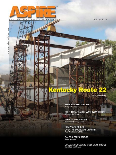
Kentucky Route 22<br />
Gratz, Kentucky<br />
Spencer creek <strong>Bridge</strong><br />
Newport, Oregon<br />
Gulf intracoastal waterway bridge<br />
Matagorda, Texas<br />
jakway park bridge<br />
Buchanan County, Iowa<br />
Humpback bridge<br />
over the boundary channel<br />
Near Washington, D.C.<br />
galena creek bridge<br />
Reno, Nevada<br />
College boulevard golf cart bridge<br />
Carlsbad, California
We support you...<br />
...while you support the world.<br />
Our advanced structural analysis and design software specializes in cable-stayed,<br />
suspension and segmental bridges. It is our dedicated support team which sets LARSA<br />
4D apart from the rest and ensures that your projects are optimized for success.<br />
Unlimited technical support and custom training sessions make LARSA 4D software the<br />
company standard at FIGG, HDR, Parsons Brinckerhoff, PBS&J, International <strong>Bridge</strong><br />
Technologies, T.Y. Lin International and many other leading engineering and design<br />
firms, around the world.<br />
D<br />
DESIGN ANALYSIS CONSTRUCTION<br />
LARSA<br />
<strong>10</strong>5 Maxess Road Suite 115N<br />
Melville, NY 11747<br />
1-800-LARSA-01<br />
www.larsa4d.com<br />
LARSA4<br />
To request a free trial of LARSA 4D visit www.larsa4d.com/trial
Photo: Prestress Services LLC.<br />
Social, Economic, and Ecological Benefits<br />
of Sustainable <strong>Concrete</strong> <strong>Bridge</strong>s<br />
8<br />
CONTENTS<br />
Features<br />
Janssen & Spaans Engineering 8<br />
Whether bread-and-butter bridges or long, complex structures<br />
and projects, concrete designs offer the best alternative.<br />
Spencer Creek <strong>Bridge</strong> 16<br />
Spencer Creek <strong>Bridge</strong> on Oregon’s scenic<br />
Coastal Highway <strong>10</strong>1 suits its setting.<br />
Gulf Intracoastal Waterway <strong>Bridge</strong> 20<br />
Combining superstructure types provides<br />
economical solution.<br />
Jakway Park <strong>Bridge</strong> 24<br />
Buchanan County constructs a bridge using<br />
ultra-high-performance concrete girders.<br />
Humpback <strong>Bridge</strong> over the Boundary Channel 28<br />
Five-stage process keeps traffic moving during<br />
construction of precast concrete segmental arch bridge<br />
near nation’s capital.<br />
Galena Creek <strong>Bridge</strong> 32<br />
A context-sensitive solution that will be the<br />
world’s largest concrete cathedral-arch bridge.<br />
College Boulevard Golf Cart <strong>Bridge</strong> 36<br />
Golf course’s cast-in-place pedestrian bridge<br />
offers clean look that complements the clubhouse.<br />
Photo: Cianbro Corp.<br />
Rendering: CH2M Hill.<br />
28<br />
32<br />
Departments<br />
Editorial 2<br />
Reader Response 4<br />
<strong>Concrete</strong> Calendar 6<br />
Perspective—Toward Green <strong>Bridge</strong> Standards 12<br />
Aesthetics Commentary 23<br />
<strong>Concrete</strong> Connections 40<br />
Maintenance, Repair, and Rehabilitation<br />
of <strong>Concrete</strong> <strong>Bridge</strong>s 41<br />
FHWA—Sustainability of <strong>Concrete</strong> <strong>Bridge</strong>s 44<br />
STATE—Infrastructure Focus and Close<br />
Relationships Work in Pennsylvania 46<br />
Safety and Serviceability 50<br />
COUNTY—Harris County, Texas 51<br />
AASHTO LRFD Specifications 52<br />
Photo: Prestress Services LLC.<br />
Advertisers Index<br />
CABA .. . . . . . . . . . . . . . . . . . . . . . Back Cover<br />
Campbell Scientific.. . . . . . . . . . . . . . . . . . 19<br />
FIGG .. . . . . . . . . . . . . . . . . . . . . . . . . . . . . . . 3<br />
Headwaters Resources. ................ 6<br />
Larsa .................Inside Front Cover<br />
PCI. ............ 31, 39, Inside Back Cover<br />
Poseidon Barge Corporation.. . . . . . . . . . . 15<br />
Shuttlelift............................ 5<br />
T.Y. Lin International .. . . . . . . . . . . . . . . . . . 7<br />
ThyssenKrupp Safway Inc. ............. 27<br />
Transpo Industries Inc.. ............... 42<br />
<strong>ASPIRE</strong>, <strong>Winter</strong> 20<strong>10</strong> | 1
EDITORIAL<br />
Photo: Ted Lacey Photography.<br />
John S. Dick, Executive Editor<br />
With this issue, <strong>ASPIRE</strong> begins its third year<br />
of exploring sustainable solutions. We find the<br />
subject more pervasive—in a most positive way—with<br />
each passing year. Both Myint Lwin and Scott Snelling<br />
address the topic in their articles. Myint, who is director,<br />
Office of <strong>Bridge</strong> Technology at the Federal Highway<br />
Administration, provides transcribed comments made<br />
during a presentation last November at the American<br />
Segmental <strong>Bridge</strong> Institute’s annual convention in<br />
Minneapolis. Scott is a senior engineer with Hardesty &<br />
Hanover in New York City and serves on the American<br />
Society of Civil Engineers’ Task Committee for<br />
Sustainable Design. From his background, he suggests<br />
what a new national standard for sustainable bridge<br />
design could look like, based on existing sustainability<br />
standards for buildings.<br />
<strong>ASPIRE</strong> has highlighted many arch bridge projects<br />
over the years including three in this issue, and there<br />
is yet another waiting in the wings for the Spring issue.<br />
<strong>The</strong> three projects in this issue are:<br />
• Spencer Creek <strong>Bridge</strong>, Newport, Ore.,<br />
• Humpback <strong>Bridge</strong> over the Boundary Channel on<br />
the George Washington Parkway near Washington,<br />
D.C. in Virginia.<br />
• Galena Creek <strong>Bridge</strong> on the I-580 Freeway<br />
Extension, near Reno, Nev., and<br />
<strong>The</strong> arch is structurally and aesthetically well-suited<br />
for creating highway bridges. Fred Gottemoeller, in his<br />
popular book titled, <strong>Bridge</strong>scape: the Art of Designing<br />
<strong>Bridge</strong>s, says about evaluating bridge types, “…if it is<br />
desirable for the structure to frame an important view,<br />
than a structural type with a curved, arched soffit will<br />
be an effective choice...Arches continue to have strong<br />
visual appeal because of their shape…Arch bridges<br />
look best where the surroundings ‘contain’ the visual<br />
thrust of the arch.”<br />
Each highlighted project uses the arch in a unique<br />
way. Each draws on context sensitivity and uses concrete<br />
Precast/Prestressed<br />
<strong>Concrete</strong> Institute<br />
Silica Fume<br />
Association<br />
Sustainability and<br />
the Art of <strong>Concrete</strong> <strong>Bridge</strong> Design<br />
1<br />
American Segmental<br />
<strong>Bridge</strong> Institute<br />
Expanded Shale Clay<br />
and Slate Institute<br />
Portland Cement<br />
Association<br />
for interesting solutions. <strong>The</strong>se projects also illustrate<br />
different techniques for building concrete arches. We<br />
believe you, too, will find these projects innovative and<br />
useful in the future consideration of such designs.<br />
Janssen & Spaans Engineering ( JSE) has played an<br />
important role in concrete bridge design for nearly 30<br />
years. <strong>The</strong>y have been involved in two record bridge<br />
spans in recent years. Since 1960, the two parallel<br />
Oneida Lake <strong>Bridge</strong>s in Brewerton, N.Y., were the world’s<br />
longest precast, prestressed concrete bridge spans at 320<br />
ft. But, in 2000, a JSE design for the Moore Haven <strong>Bridge</strong><br />
over the Okeechobee Waterway in Florida resulted in<br />
a three-span unit with a 320-ft-long main span, tying<br />
the record. <strong>The</strong> Kentucky Route 22 project, shown on<br />
the cover and mentioned in the FOCUS on JSE, when<br />
completed, will be the new world record holder, with a<br />
main span of 325 ft. Along the way, techniques pioneered<br />
by JSE and used in the design and construction of<br />
spliced girder bridges have become commonplace. We<br />
are proud to feature them in this issue.<br />
<strong>The</strong> Jakway Park <strong>Bridge</strong> in Iowa not only uses ultrahigh-performance<br />
concrete at a design compressive<br />
strength of 21,500 psi but employs a special new<br />
shape called the Pi girder (owing to its cross-section’s<br />
resemblance to the Greek letter). Created by the<br />
Massachusetts Institute of Technology and the Federal<br />
Highway Administration, the shape takes advantage of<br />
the material’s unique properties.<br />
<strong>The</strong> Pennsylvania Department of Transportation<br />
is this issue’s featured state. <strong>The</strong> concrete industry<br />
acknowledges Pennsylvania as home to the nation’s<br />
first modern precast, prestressed concrete bridge; a<br />
cutting edge solution for the time. Today, PennDOT<br />
continues its state-of-the-art applications of concrete<br />
technology.<br />
Each article serves as a testament to wise decisions<br />
by designers and good investments by owners on behalf<br />
of the traveling public. As always, we hope you enjoy<br />
and benefit from their presentation.<br />
EPOXY INTEREST GROUP<br />
Epoxy Interest Group<br />
Log on NOW at<br />
www.aspirebridge.org<br />
and take the <strong>ASPIRE</strong> Reader Survey.<br />
Executive Editor: John S. Dick<br />
Managing Technical Editor: Dr. Henry G.<br />
Russell<br />
Managing Editor: Craig A. Shutt<br />
Editorial Administration: James O. Ahtes Inc.<br />
Art Director: Mark Leader,<br />
Leader Graphic Design Inc.<br />
Layout Design: Jim Henson,<br />
Leader Graphic Design Inc.<br />
Electronic Production: Chris Bakker,<br />
Jim Henson, Leader Graphic Design Inc.<br />
Ad Sales: Jim Oestmann<br />
Phone: (847) 838-0500 • Cell: (847) 924-5497<br />
Fax: (847) 838-0555<br />
joestmann@arlpub.com<br />
Reprint Sales: Mark Leader<br />
(847) 564-5409<br />
e-mail: mark@leadergraphics.com<br />
Publisher:<br />
Precast/Prestressed <strong>Concrete</strong> Institute,<br />
James G. Toscas, President<br />
Editorial Advisory Board:<br />
Susan N. Lane, Portland Cement Association<br />
(PCA)<br />
John S. Dick, Precast/Prestressed <strong>Concrete</strong><br />
Institute (PCI)<br />
William R. Cox, American Segmental <strong>Bridge</strong><br />
Institute (ASBI)<br />
David McDonald, Epoxy Interest Group (EIG)<br />
Dr. Henry G. Russell, Managing Technical Editor<br />
POSTMASTER: Send address changes to<br />
<strong>Aspire</strong>,<br />
200 W. Adams St., Suite 2<strong>10</strong>0,<br />
Chicago, IL 60606.<br />
Standard postage paid at Chicago, IL, and<br />
additional mailing offices.<br />
<strong>Aspire</strong> (Vol. 4, No. 1),<br />
ISSN 1935-2093 is published quarterly<br />
by the Precast/Prestressed <strong>Concrete</strong> Institute,<br />
200 W. Adams St., Suite 2<strong>10</strong>0,<br />
Chicago, IL 60606.<br />
Copyright 20<strong>10</strong>, Precast/Prestressed <strong>Concrete</strong><br />
Institute.<br />
If you have a project to be con sidered for <strong>Aspire</strong>,<br />
send information to <strong>Aspire</strong>,<br />
200 W. Adams St., Suite 2<strong>10</strong>0,<br />
Chicago, IL 60606<br />
phone: (312) 786-0300<br />
www.aspirebridge.org<br />
e-mail: info@aspirebridge.org<br />
Cover:<br />
Kentucky Route 22, Gratz, Ky.<br />
Photo: Prestress Services LLC.<br />
2 | <strong>ASPIRE</strong>, <strong>Winter</strong> 20<strong>10</strong>
Penobscot Narrows <strong>Bridge</strong><br />
& Observatory, Maine<br />
I-280 Veterans’ Glass City<br />
Skyway, Ohio<br />
OWNER: Maine Department<br />
of Transportation<br />
DESIGNER: FIGG<br />
CONTRACTOR:<br />
Cianbro/Reed & Reed, JV<br />
<strong>The</strong> world’s tallest public bridge<br />
observatory at the top of the 420’<br />
western pylon provides 360 degree<br />
vistas of Maine for visitors from May<br />
through October. <strong>The</strong> cable-stay<br />
bridge features a 1,161’ main span<br />
and was opened to traffic on<br />
December 30, 2006. Aesthetics<br />
selected by the community center<br />
around a bridge theme of “Granite,<br />
Simple and Elegant”. This bridge<br />
has received numerous awards,<br />
including the George S. Richardson<br />
medal from the International <strong>Bridge</strong><br />
Conference and the ASBI <strong>Bridge</strong><br />
Award of Excellence.<br />
Cut-A-Way View showing<br />
Interstitial Space<br />
(Filled with grout)<br />
and 7-Wire Strand<br />
(Epoxy or HDPE Coated)<br />
Cradle Outer Sheath<br />
Sheath Pipe Connection<br />
Cable-Stay<br />
<strong>Bridge</strong> Technology<br />
<strong>The</strong> FIGG Cable-Stay Cradle System Invention – first used<br />
in the I-280 Veterans’ Glass City Skyway, Ohio & Penobscot<br />
Narrows <strong>Bridge</strong> & Observatory, Maine – was designed to<br />
revolutionize cable-stay bridges. <strong>The</strong> cradle is one unit that<br />
goes through the pylon. Among the cradle's many benefits are<br />
that it allows for unlimited stay sizes and makes it possible to<br />
remove, inspect and replace individual stay strands. Awards<br />
include: the 2007 ASCE Charles Pankow Award for<br />
Innovation, the NOVA Award from the Construction Innovation<br />
Forum, the 2006 NSPE New Product Award and the 2006<br />
Modern Marvels Invent Now Top 25 Inventions (selected from<br />
4000 entries)<br />
1.800.358.3444 ∫ www.figgbridge.com<br />
Cable-Stayed Strands<br />
OWNER: Ohio Department<br />
Of Transportation<br />
DESIGNER: FIGG<br />
CONTRACTOR: Bilfinger<br />
Berger Civil Inc.<br />
Toledo’s landmark cable-stay bridge<br />
features 612.5’ spans on either side<br />
of a single pylon and incorporates<br />
stainless steel cable casings and a<br />
pylon with four sides of glass on the<br />
top 196’. <strong>The</strong> custom glass reflects<br />
the community’s vision and honors<br />
their heritage in the glass industry. At<br />
night, LED lights behind the glass<br />
create dramatic lighting celebrating<br />
seasons and holidays. This bridge<br />
opened to traffic in June 2007 and<br />
has received numerous awards<br />
including the NCSEA Outstanding<br />
Project Award and the ASBI <strong>Bridge</strong><br />
Award of Excellence.<br />
Creating <strong>Bridge</strong>s As Art ®
READER RESPONSE<br />
w w w . a s p i r e b r i d g e . o r g<br />
T H E C O N C R E T E B R I D G E M A G A Z I N E<br />
4 th Street <strong>Bridge</strong><br />
ROUTE 70 OvER manasqUan RivER/<br />
sEPTEmBER 11 mEmORiaL BRidgE<br />
Ocean and Monmouth Counties, New Jersey<br />
ROUTE 31 BRidgE OvER<br />
canandaigUa OUTLET<br />
Vi lage of Lyons,<br />
Wayne County, New York<br />
ROsL Yn viadUcT<br />
Nassau County, New York<br />
cincinnaTi/nORTHERn KEnTUcKY<br />
inTERnaTiOnaL aiRPORT TaXiWaY<br />
‘n’ BRidgE<br />
Erlanger, Kentucky<br />
Pueblo, Colorado<br />
Fa l 2009<br />
Editor,<br />
I commend you on a beautiful, up-todate,<br />
relevant, and educational magazine.<br />
<strong>The</strong>refore I was surprised to see in the<br />
FHWA article on the American Recovery<br />
and Reinvestment Act [see <strong>ASPIRE</strong> Fall<br />
2009, p. 42] a background photograph of<br />
a person marking up a bridge technical<br />
design drawing using a fountain pen and<br />
a hand compass. While I still am partial to<br />
the beautiful nuance of using varying line<br />
weights on older, hand-drawn technical<br />
drawings and bemoan the poor penmanship<br />
of younger engineers who never took a<br />
manual drafting class, the last time I was<br />
required to use a fountain pen was in the<br />
fourth grade (40 years ago) and for a hand<br />
compass it was in college (over 25 years<br />
ago). While the photograph accompanying the<br />
FHWA article was nostalgic, it doesn’t at all<br />
represent the computer drafting and complex<br />
4D modeling used by today’s engineer, or<br />
ARRA projects.<br />
Roger Haight<br />
Parsons Brinckerhoff<br />
New York, NY<br />
[Editor’s Reply]<br />
Roger…<br />
Thank you for the compliments. It is always<br />
encouraging to hear that we are achieving our<br />
goals to bring relevant technical information to<br />
bridge designers in an attractive and appreciated<br />
package. I have to admit that I too pondered the<br />
use of instruments from a bygone era shown<br />
in the background of this feature. I wondered if<br />
others would take notice. It appears that I am<br />
older than you! I used an ink compass, LeRoy<br />
lettering instruments, and a set of Koh-I-Noor<br />
Rapidograph ink pens to create what I think<br />
were very attractive standard drawings for the<br />
Wyoming Highway Department in 1965 and ‘66.<br />
<strong>The</strong> use of this background contrasts greatly<br />
with the exceptionally contemporary program<br />
we know as the ARRA. Maybe that’s the irony.<br />
[Roger Haight’s Response]<br />
Yes, it was good to hear you reminisce about<br />
the good old days—you are much older than<br />
I am!!<br />
Editor’s Note<br />
Additional copies of <strong>ASPIRE</strong> may be purchased<br />
for a nominal price by writing to the Editor<br />
through “Contact Us” at the <strong>ASPIRE</strong> website,<br />
www.aspirebridge.org. A free subscription can be<br />
arranged there using the “Subscribe” tab.<br />
Providing Corrosion Protection<br />
High Performance at a low cost – Epoxy-Coated Reinforcing<br />
www.epoxyinterestgroup.org<br />
BRIDGES<br />
EPOXY INTEREST GROUP<br />
For additional<br />
information<br />
on EIG log-on<br />
to our Web site.<br />
EPOXY INTEREST GROUP<br />
CORROSION-RESISTANCE<br />
OF REINFORCING BARS:<br />
An Accelerated Test<br />
EPOXY INTEREST GROUP<br />
EPOXY INTEREST GROUP<br />
Corrosion rEsisTAnCE<br />
of Epoxy-Coated reinforcing Bars<br />
<strong>Bridge</strong> substructure in a Marine Environment<br />
©Photo courtesy of FIGG, photographer Tim Davis.<br />
11664_EIG_adv_bridge_brochure.indd 1<br />
4 | <strong>ASPIRE</strong>, <strong>Winter</strong> 20<strong>10</strong><br />
7/31/09 <strong>10</strong>:51:19 AM
Shuttlelift’s ISL and SL mobile gantry cranes provide practical, efficient<br />
and robust lifting solutions for the bridge building industry.<br />
SL 300 – Minnesota, Minneapolis<br />
www.shuttlelift.com • USA Tel: +1 920.743.8650 • UK Tel: +44 (0) 2392 230 811
CONTRIBUTING AUTHORS<br />
MANAGING<br />
TECHNICAL EDITOR<br />
M. Myint Lwin is director<br />
of the FHWA Office of <strong>Bridge</strong><br />
Technology in Washington,<br />
D.C. He is responsible for the<br />
National Highway <strong>Bridge</strong><br />
Program direction, policy, and<br />
guidance, including bridge<br />
technology development,<br />
deployment and education, and<br />
the National <strong>Bridge</strong> Inventory<br />
and Inspection Standards.<br />
Dr. Dennis R. Mertz is<br />
professor of civil engineering<br />
at the University of Delaware.<br />
Formerly with Modjeski and<br />
Masters Inc. when the LRFD<br />
Specifications were first written,<br />
he has continued to be actively<br />
involved in their development.<br />
Scott Snelling is a<br />
mechanical and structural<br />
engineer with Hardesty &<br />
Hanover LLP in New York City.<br />
He serves on the American<br />
Society of Civil Engineers Task<br />
Committee for Sustainable<br />
Design and the Structural<br />
Engineering Institute’s<br />
sustainability committee. He<br />
has served in the field with<br />
Engineers Without Borders and<br />
<strong>Bridge</strong>s to Prosperity.<br />
Frederick Gottemoeller<br />
is an engineer and architect,<br />
who specializes in the aesthetic<br />
aspects of bridges and<br />
highways. He is the author of<br />
<strong>Bridge</strong>scape, a reference book<br />
on aesthetics and was deputy<br />
administrator of the Maryland<br />
State Highway Administration.<br />
HOW TO<br />
combat global warming,<br />
reduce the<br />
production of greenhouse gases,<br />
and builda<br />
stronger infrastructure.<br />
CONCRETE CALENDAR 20<strong>10</strong><br />
For links to websites, email addresses, or telephone numbers for these events, go to<br />
www.aspirebridge.org.<br />
February 2–5, 20<strong>10</strong><br />
World of <strong>Concrete</strong><br />
Las Vegas Convention Center, Las Vegas, Nev.<br />
February 17-18, 20<strong>10</strong><br />
20<strong>10</strong> ASBI Seminar on Design and<br />
Construction of Segmental & Cable-<br />
Supported <strong>Concrete</strong> <strong>Bridge</strong>s<br />
Mariott Hotel, Denver, Colo.<br />
February 24-26, 20<strong>10</strong><br />
NCBC <strong>Concrete</strong> <strong>Bridge</strong> Conference<br />
Hyatt Regency, Phoenix, Ariz.<br />
March 21-25, 20<strong>10</strong><br />
ACI Spring Convention<br />
Sheraton Hotel, Chicago, Ill.<br />
April 8-9, 20<strong>10</strong><br />
20<strong>10</strong> FHWA <strong>Bridge</strong> Engineering<br />
Conference: Highways for LIFE and<br />
Accelerated <strong>Bridge</strong> Construction<br />
Hyatt Regency Grand Cypress, Orlando, Fla.<br />
May 23-27, 20<strong>10</strong><br />
AASHTO Subcommittee on <strong>Bridge</strong>s and<br />
Structures Annual Meeting<br />
Sacramento, Calif.<br />
May 29 – June 2, 20<strong>10</strong><br />
Third International CEB-fib Congress<br />
and Exhibition<br />
PCI Annual Convention<br />
PCI-FHWA National <strong>Bridge</strong> Conference<br />
Gaylord National Resort & Convention Center,<br />
National Harbor, Md.<br />
June 6-9, 20<strong>10</strong><br />
International <strong>Bridge</strong> Conference<br />
David L. Lawrence Convention Center,<br />
Pittsburgh, Pa.<br />
September 23-26, 20<strong>10</strong><br />
PCI Committee Days<br />
Chicago, Ill.<br />
October 11-12, 20<strong>10</strong><br />
20<strong>10</strong> ASBI 22nd Annual Convention<br />
<strong>The</strong> Westin Bayshore, Vancouver, British Columbia<br />
April 12-13, 20<strong>10</strong><br />
20<strong>10</strong> ASBI Grouting Certification<br />
Training<br />
October 24-28, 20<strong>10</strong><br />
J.J. Pickle Research Campus, <strong>The</strong> Commons<br />
ACI Fall Convention<br />
Center, Austin, Tex.<br />
NEWGreenAd4.916sq:Layout 1 2/17/09 <strong>10</strong>:38 <strong>The</strong> Westin AM Page Convention 1 Center, Pittsburgh, Pa.<br />
SPECIFY FLY ASH<br />
(a recovered resource)<br />
as a replacement for cement in concrete.<br />
Photo: Ted Lacey Photography.<br />
Dr. Henry G. Russell is an engineering consultant,<br />
who has been involved with the applications of concrete in<br />
bridges for over 35 years and has published many papers<br />
on the applications of high-performance concrete.<br />
When you specify fly ash as replacement for<br />
cement in concrete, you help reduce CO2<br />
emissions from cement production, conserve<br />
landfill space, and decrease water usage.<br />
You also enhance workability and chemical<br />
attack resistance, increase strength and<br />
produce more durable concrete.<br />
Contact Headwaters Resources<br />
for free technical literature and<br />
information on how fly ash use<br />
benefits the environment and<br />
produces better concrete.<br />
1-888-236-6236<br />
www.flyash.com<br />
6 | <strong>ASPIRE</strong>, <strong>Winter</strong> 20<strong>10</strong>
February 17-18<br />
Construction Practices<br />
S e m i n a r<br />
Denver, Colorado<br />
1<br />
AMERICAN SEGMENTAL BRIDGE INSTITUTE<br />
April 12-13<br />
20<strong>10</strong> Grouting Certification<br />
T r a i n i n G<br />
J.J. Pickle Research Campus<br />
University of Texas, Austin<br />
Mark Your Calendar Today!<br />
For these three important 1 events.<br />
October 11-12<br />
20<strong>10</strong> annual aSBi<br />
ConvenT ion<br />
Vancouver, BC, Canada<br />
For further details visit<br />
www.asbi-assoc.org<br />
11760_ASBI_<strong>ASPIRE</strong>_win20<strong>10</strong>.indd 1<br />
12/11/09 1:33:31 PM<br />
David Kreitzer Lake Hodges Bicycle Pedestrian <strong>Bridge</strong><br />
San Diego, California — 2009 PCI Design Award Winner<br />
<strong>The</strong> David Kreitzer Lake Hodges Bicycle Pedestrian <strong>Bridge</strong> is the<br />
world’s longest stress-ribbon bridge. With a total length of 990 feet<br />
and a 16-inch-thick deck, the result is a thin ribbon of concrete with<br />
a remarkable depth-to-span ratio of 1:248. T.Y. Lin International was<br />
retained by San Dieguito River Park Joint Powers Authority to provide<br />
concept studies, detailed design, and resident engineering services.<br />
This unique design project was delivered on time and within budget.<br />
Two Harrison Street, Suite 500<br />
San Francisco, California 94<strong>10</strong>5<br />
tel: 415.291.3700 | fax: 415.433.0807 | www.tylin.com<br />
<strong>ASPIRE</strong>, <strong>Winter</strong> 20<strong>10</strong> | 7
FOCUS<br />
<strong>Concrete</strong> Philosophy Drives<br />
Janssen & Spaans<br />
by Craig A. Shutt<br />
JSE worked under a design-build format to create the<br />
design for the Des Plaines River Valley <strong>Bridge</strong> on I-355 in<br />
Lemont, Ill. <strong>The</strong> bridge features a combination of 18 spans<br />
with simple pretensioned concrete beams and 17 spans with<br />
post-tensioned spliced girders over its 1.3-mile length.<br />
Photos: Illinois State Toll Highway Authority.<br />
Whether breadand-butter<br />
bridges<br />
or long, complex<br />
structures and<br />
projects, concrete<br />
designs offer the<br />
best alternative<br />
In its nearly 30 years of operation, Janssen<br />
& Spaans Engineering Inc. (JSE) has created<br />
designs for a multitude of bridges, including<br />
some highly complex ones that have<br />
become its forte. Throughout that history,<br />
it has found one maxim to be true: Properly<br />
designed, a concrete bridge will outlast,<br />
outperform, and underbid any alternative.<br />
“Every time we perform cost-alternate<br />
studies or work on design-build projects<br />
with contractors estimating construction<br />
costs, we find that concrete superstructures<br />
are consistently more economical than<br />
the corresponding steel superstructure<br />
alternates.” says Leo Spaans, founder<br />
and co-owner of Indianapolis-based JSE.<br />
“In addition to the upfront construction<br />
cost savings of concrete over steel, we<br />
have witnessed continued cost savings<br />
throughout the life of these structures.<br />
<strong>The</strong>se savings result from lower maintenance<br />
requirements of concrete structures and<br />
better long-term durability.”<br />
Over the years, this conclusion has been<br />
confirmed by a number of projects in<br />
which alternative designs were prepared.<br />
An example is the preparatory work<br />
completed for the Des Plaines River Valley<br />
<strong>Bridge</strong> on I-355 in Lemont, Ill. Created<br />
under a performance-based specification,<br />
the structure features 18 spans with<br />
simple precast, pretensioned concrete<br />
beams and 17 spans with post-tensioned<br />
spliced girders over its 1.3-mile length. <strong>The</strong><br />
$125-million project, which includes 612<br />
girders using three different depths, needed<br />
this combined approach to efficiently place<br />
piers in a complex terrain. (For more on<br />
this project, see the Spring 2008 issue of<br />
<strong>ASPIRE</strong>.)<br />
8 | <strong>ASPIRE</strong>, <strong>Winter</strong> 20<strong>10</strong>
JSE created this option along with a steelplate<br />
girder alternative, using two design<br />
teams that each presented their approach to<br />
the contractor, Walsh Construction Group<br />
in Chicago. “Walsh did the calculations<br />
and added up all the costs and chose the<br />
concrete design,” Spaans says. “<strong>The</strong>y made<br />
the choice based on the bottom line.”<br />
Close Relations with<br />
Contractors<br />
JSE works closely with contractors, especially<br />
when they are using their preferred delivery<br />
method, design-build. “We love the designbuild<br />
system,” he says. “It helps create a<br />
level of freedom that permits us to be as<br />
efficient as possible. We like working closely<br />
with contractors. <strong>The</strong>y’re only interested in<br />
being efficient and in constructing the best<br />
design possible.”<br />
A recent example is the U.S. Route 460<br />
Connector project in Buchanan County,<br />
Va., for which JSE provided design-build<br />
engineering services. <strong>The</strong> 1733-ft-long,<br />
six-span twin segmental box-girder bridge<br />
features two main spans of 489 ft with<br />
the box varying from 31 ft to 12 ft 6 in. in<br />
depth. <strong>The</strong> bridge is supported by H-shaped<br />
concrete columns with a maximum pier<br />
height of 220 ft, the tallest bridge piers in<br />
the state. <strong>The</strong> construction cost for JSE’s<br />
design beat the next closest option by $3<br />
million, on top of being the most responsive<br />
bid, based on the bids being weighted for<br />
technical proposal scores.<br />
JSE designers relish the discussions that<br />
hone the final creation to make it as<br />
efficient as the talents of both sides will<br />
allow. “<strong>The</strong> contractors take our ideas,<br />
directly translate them into reality and give<br />
us feedback,” he says. “It’s a very interactive<br />
process with good give and take.” Typically,<br />
weekly meetings are held as the project gets<br />
underway, to learn how smoothly the two<br />
groups will work and how close their visions<br />
of the final design are.<br />
<strong>The</strong> effectiveness that this process provides<br />
when compared to the typical design-bidbuild<br />
process can be striking, he adds.<br />
“When we are designing without having<br />
any idea who the contractor will be, we<br />
need to create engineering drawings that<br />
everyone can bid on. That lack of interaction<br />
keeps it from being as effective as possible<br />
and playing to the individual contractor’s<br />
own skills.” Value-engineering processes<br />
can follow, but those steps occur after the<br />
bidding and add time. “Design-build speeds<br />
up the process greatly.”<br />
Speed is Key Goal<br />
<strong>The</strong> need for speed is a major ingredient<br />
in owners’ goals today, he notes. Owners<br />
want projects completed faster to<br />
bring them online quicker and to have<br />
construction disrupt events for a shorter<br />
period, reducing user costs and increasing<br />
worker safety. <strong>The</strong> firm’s work on the I-70<br />
project in Indianapolis, Ind., shows the<br />
dramatic improvements that can be made<br />
in construction speed with a design-build<br />
process.<br />
<strong>The</strong> $175-million project replaced all<br />
roadways and upgraded 23 bridges along<br />
a 6-mile stretch of highway. Two new<br />
bridges were constructed with precast,<br />
prestressed concrete I-beams—a design, he<br />
notes, that “is almost impossible to beat.”<br />
<strong>The</strong> entire project took only <strong>10</strong> months,<br />
compared to an estimated 2-year process<br />
for a traditional design-bid-build project. JSE<br />
took 3 months to create the drawings and<br />
then dealt with construction issues for the<br />
remaining 7 months. “This approach saved<br />
a tremendous amount of time.”<br />
<strong>The</strong> success of this approach can be seen in<br />
the company’s own projects in Indiana. JSE<br />
has a 70% success rate in winning projects<br />
that it proposes with a design-build delivery<br />
method, he says. “We’ve been extremely<br />
successful with it in Indiana, because it saves<br />
a tremendous amount of time.”<br />
‘We find that<br />
concrete superstructures<br />
are consistently more<br />
economical than<br />
the corresponding<br />
steel superstructure<br />
alternates.’<br />
<strong>The</strong> $175-million “Super 70”<br />
bridge project in Indianapolis<br />
involves revamping 6 miles of<br />
I-70, comprising all roadway<br />
and 23 bridges. In addition,<br />
two new bridges were<br />
constructed with precast,<br />
prestressed concrete I-beams.<br />
<strong>The</strong> design-build project was<br />
completed in only <strong>10</strong> months.<br />
Photo: © 1800TOPSITE.com.<br />
<strong>ASPIRE</strong>, <strong>Winter</strong> 20<strong>10</strong> | 9
‘Spliced bulb-tee girders are going to drive<br />
concrete strengths higher.’<br />
New Partnerships Forming<br />
<strong>The</strong> company also has been gaining<br />
success with public-private partnerships,<br />
which it sees growing as government<br />
agencies want to gain additional funding<br />
and private entities gain benefits from<br />
operating the roadway. One such project<br />
is currently underway in one of Canada’s<br />
western provinces, where the roadway<br />
and 35 bridges (90% of them proposed to<br />
be constructed with prestressed concrete<br />
I-beams) are being improved. <strong>The</strong> $1-billion<br />
project is being funded by a private group,<br />
which will build and then maintain the<br />
highway.<br />
“<strong>The</strong> owners are demanding anything<br />
possible to prolong life, because they are<br />
responsible for maintenance,” he says.<br />
“<strong>The</strong>se private entities understand that to<br />
keep the project profitable, the owner must<br />
look long term and account for all expenses<br />
throughout the structure’s service life.”<br />
One way to lower maintenance and<br />
increase durability is using a concrete mix<br />
containing fly ash and a high-range, waterreducing<br />
admixture. <strong>The</strong>se mixtures achieve<br />
high compressive strengths and have<br />
a low permeability. Additionally for deck<br />
protection, some owners are specifying<br />
an overlay of silica fume concrete, further<br />
increasing the long-term durability of the<br />
deck.<br />
Durability a Requirement<br />
Durability is a key concern as owners<br />
look to extend service life to <strong>10</strong>0 years or<br />
more. <strong>Concrete</strong> bridges can provide that<br />
attribute, Spaans says, by focusing more<br />
attention on bearings and expansion joints.<br />
“<strong>The</strong> use of integral abutments to eliminate<br />
or reduce the number of bearings, and<br />
the use of elastomeric bearings, can aid<br />
durability greatly,” he says. Denser concrete,<br />
especially through adding fly ash and<br />
other admixtures, also offers potential for<br />
extending service life. “<strong>The</strong> more rigid the<br />
structure, the less vibration will be created<br />
and the better opportunities to avoid<br />
cracking.”<br />
But Spaans doesn’t believe a <strong>10</strong>0-year<br />
service life will achieve the goals that bridge<br />
owners are hoping it will. “<strong>The</strong> bigger<br />
problem over that period is the functionality<br />
of the roadway and the bridges,” he<br />
explains. As usage grows and codes<br />
change, bridges will need to be upgraded<br />
or replaced to handle traffic and satisfy new<br />
criteria rather than be replaced because<br />
they have worn out. “<strong>The</strong> bridges may<br />
still have life, but they will be functionally<br />
obsolete <strong>10</strong>0 years from now,” he argues.<br />
“Current standards provide bridges with<br />
enough service life to last 75 years, and that<br />
durability will be enough.”<br />
High-performance concrete that focuses<br />
on improving concrete strengths, however,<br />
is offering new opportunities, especially for<br />
spliced-girder bridges. “Spliced bulb-tee<br />
girders are going to drive concrete strengths<br />
higher,” he says. “Ten years ago, if we<br />
had said we wanted concrete of 7000 psi<br />
or higher, people wouldn’t have known<br />
what to do with it. That has changed.<br />
<strong>The</strong> biggest trend in bridge design is the<br />
Janssen & Spaans’ Long Prestressed <strong>Concrete</strong> History<br />
Janssen & Spaans opened its doors in the early 1980s, but founders Hubert Janssen and Leo<br />
Spaans had many years of experience with concrete bridge designs before that. <strong>The</strong> two<br />
previously had worked together in the Netherlands for the engineering firm BVN. That company<br />
had a long history with prestressed concrete designs, as one of its own founders had been a<br />
student of Eugene Freyssinet of France, acknowledged as the inventor of prestressed concrete.<br />
Spaans came to America in 1977 as part of a BVN team that worked with the Indiana-based<br />
engineering firm STS. Shortly after, the two companies merged to create BVN-STS, which later<br />
was purchased by HDR. Janssen and Spaans broke off on their own a few years later, focusing<br />
at first on segmental bridge designs. <strong>The</strong> company soon expanded its expertise beyond<br />
segmental bridges to all types and ultimately to pavement and roadwork projects as well.<br />
Today, JSE’s 65 employees work on more roadwork projects than bridges—but they also create<br />
more bridges than at any time in the past, an indication of the growth it has experienced.<br />
new properties we’re able to achieve with<br />
concrete. We can gain higher strength and<br />
more durability, which aids design creativity<br />
and functionality.”<br />
Sand-Lightweight <strong>Concrete</strong><br />
Grows<br />
Sand-lightweight (SLW) concrete also is<br />
being used more often, he notes. “It can<br />
greatly reduce the weight for transporting<br />
and erecting larger beams for new projects.”<br />
Unless there is significant widening involved,<br />
there is less need to use SLW concrete<br />
when replacing only superstructures<br />
in rehabilitation projects, he notes.<br />
“Foundations and substructures typically<br />
are robust enough that it does not create a<br />
problem to replace the superstructure with<br />
new materials.”<br />
An example of JSE’s use of SLW concrete<br />
is the Kentucky Route 22 project currently<br />
underway in Gratz, Ky. Designed as a steel<br />
plate girder bridge, the precaster joined<br />
with JSE to propose a 900-ft-long, four-span<br />
(175, 200, 325, and 200 ft) spliced bulb-tee<br />
girder design. This design yielded a savings<br />
of more than $800,000 when compared to<br />
the as-bid steel design.<br />
<strong>The</strong> main span features a 325-ft-long<br />
spliced bulb-tee girder, the longest in the<br />
country to feature this type of construction.<br />
<strong>10</strong> | <strong>ASPIRE</strong>, <strong>Winter</strong> 20<strong>10</strong>
<strong>The</strong> Kentucky Route 22 project in Gratz, Ky.,<br />
was redesigned by JSE from a steel-plate<br />
girder bridge to a four-span, 909-ft-long<br />
spliced bulb-tee girder design that saved<br />
about $800,000 from the previous design.<br />
<strong>The</strong> 325-ft main span provides a record<br />
length for construction of this type.<br />
Photos: Janssen & Spaans Engineering.<br />
<strong>The</strong>se recommendations can range from<br />
modest repairs through total replacement.<br />
As the needs for repairs and replacement<br />
bridges grow in coming years, Spaans<br />
anticipates more improvements in concrete<br />
engineering and handling, making it even<br />
more the dominant material. “If you design<br />
properly, it’s almost impossible to create a<br />
better bridge using steel,” he says. That<br />
philosophy is helping the company produce<br />
economical designs and grow during the<br />
current recessionary times.<br />
SLW concrete was used to reduce its weight<br />
for handling purposes. <strong>The</strong> haunched pier<br />
segments are 16 ft deep, while the 9-ft-deep<br />
drop-in girders have a maximum length of<br />
185 ft. <strong>The</strong> bridge will be completed in the<br />
summer for the Kentucky Transportation<br />
Cabinet.<br />
Equipment Capabilities<br />
Expand<br />
Aiding these projects are the improvements<br />
that precasters and erectors have made in<br />
their equipment, including special trucks for<br />
transporting large components, creativity<br />
in barging girders to the site, and larger<br />
and more adept cranes to pick and place<br />
pieces rapidly and efficiently. “<strong>The</strong>re have<br />
been significant improvements in the past<br />
<strong>10</strong> years to aid transport and handling. Ten<br />
years ago, if we’d said we were going to<br />
create spliced bulb-tee girders for a span of<br />
325 ft, they’d have said they couldn’t get<br />
the pieces to the site. But today we can do<br />
it.”<br />
An example of the creativity that can be<br />
achieved with designs is the Fulton Road<br />
bridge replacement project in Cleveland,<br />
Ohio, for which JSE performed construction<br />
engineering services. <strong>The</strong> 1573-ft-long<br />
bridge features 35 spans of AASHTO Type<br />
III precast, prestressed concrete girders<br />
supported on five approach spans and six<br />
2<strong>10</strong>-ft-long precast, post-tensioned concrete<br />
arch spans with cast-in-place concrete<br />
piers, spandrel columns, and transverse cap<br />
beams. <strong>The</strong> bridge spans a park, the city<br />
zoo, a creek, and two active railroad lines.<br />
<strong>The</strong> arch spans have a parabolic profile and<br />
a 41 ft 8 in. rise, consisting of three precast<br />
concrete sections, comprising two identical<br />
end segments and a crown segment.<br />
<strong>The</strong> owner’s design specified cable stays<br />
for the erection of the arch pieces for two<br />
of the spans. JSE was able to develop an<br />
alternate erection scheme for the contractor<br />
that eliminated the cable stays by using<br />
conventional falsework, greatly speeding up<br />
the erection time while lowering erection<br />
costs. During erection, arch struts were<br />
installed between arch lines by bolting them<br />
to the face of the arches. <strong>The</strong> project was<br />
completed in the fall of 2009. (For more on<br />
this project, see the Spring 2009 issue of<br />
<strong>ASPIRE</strong>.)<br />
Rehabilitation of existing bridges also is<br />
becoming a bigger part of JSE’s business.<br />
<strong>The</strong> firm has an agreement with the state<br />
of Indiana to inspect and recommend<br />
action for bridges. One of the firm’s<br />
groups is devoted exclusively to inspecting<br />
bridges, creating reports to recommend<br />
improvements, and following through with<br />
design plans if the state requires them.<br />
“Despite the economy, we are expanding<br />
and pursuing work in new areas of the<br />
country, as well as internationally.” Those<br />
proposals include ones in Alberta, Canada,<br />
as well as the Middle East and Libya. In all of<br />
those projects, no doubt, Janssen & Spaans<br />
will build an efficient, attractive, and costeffective<br />
structure—and it more than likely<br />
will be made with concrete.<br />
For more information on this or other<br />
projects, visit www.aspirebridge.org.<br />
<strong>The</strong> Fulton Road bridge replacement<br />
project in Cleveland, Ohio, features 35<br />
spans of AASHTO Type III precast concrete<br />
girders supported on five approach spans<br />
and six 2<strong>10</strong>-ft-long precast concrete, posttensioned<br />
arch spans with cast-in-place<br />
concrete piers, spandrel columns, and<br />
transverse cap beams. <strong>The</strong> bridge spans a<br />
park, the city zoo, a creek, and two active<br />
railroad lines.<br />
<strong>ASPIRE</strong>, <strong>Winter</strong> 20<strong>10</strong> | 11
PERSPECTIVE<br />
Using SCMs, the Arthur Ravenel Jr. <strong>Bridge</strong> over the Cooper<br />
River in South Carolina used highly impermeable concrete<br />
to achieve a <strong>10</strong>0-year service life. Photo: PB.<br />
Toward<br />
Green <strong>Bridge</strong><br />
Standards<br />
<strong>The</strong> following article presents the<br />
opinions of the author and not<br />
necessarily those of the publishers of<br />
<strong>ASPIRE</strong>. Readers are encouraged to<br />
respond with their opinions or ideas<br />
about this subject.<br />
by Scott Snelling,<br />
Hardesty & Hanover LLP<br />
Sustainable or “green” design has<br />
entered the public consciousness and<br />
the mainstream media. Taxpayers,<br />
voters, politicians, and policymakers<br />
want assurance that public funds are<br />
being used to build environmentally<br />
sensitive infrastructure. <strong>The</strong> American<br />
Society of Civil Engineers (ASCE)<br />
recently launched an initiative to create<br />
a standard for defining and certifying<br />
green infrastructure projects and<br />
design professionals. While it is not<br />
yet clear when ASCE will be ready to<br />
introduce such a standard or if another<br />
organization will become pre-eminent,<br />
it is clear that sooner than later, a green<br />
standard will be incorporated into the<br />
bridge industry in the United States. In<br />
the concluding section of this article,<br />
the framework of a future green bridge<br />
standard is proposed from a review of<br />
the existing green standards that have<br />
been put into practice in other segments<br />
of the construction industry.<br />
Existing Green Standards<br />
<strong>The</strong>se standards include LEED, SPiRiT,<br />
and Greenroads. LEED is the acronym for<br />
Leadership in Energy & Environmental<br />
Design; this standard certifies green<br />
building and neighborhoods. LEED is<br />
administered by the United States Green<br />
Building Council, a non-profit organization<br />
founded in 1993. SPiRiT is the Sustainable<br />
Project Rating Tool developed by the U.S.<br />
Army for their facilities. Since 2000, all<br />
new army facilities have been required<br />
to be built to LEED or SPiRiT standards.<br />
Greenroads was introduced in 2009 to<br />
certify roadway and pavement projects. This<br />
standard was developed at the University of<br />
Washington with funding from the United<br />
States Department of Transportation and<br />
several state departments of transportation.<br />
Greenroads’ documentation states, “A<br />
future system focused on structures [i.e.,<br />
bridges, tunnels, and walls] could be<br />
incorporated into Greenroads, but none<br />
currently exists.”<br />
12 | <strong>ASPIRE</strong>, <strong>Winter</strong> 20<strong>10</strong>
Evaluating Infrastructure<br />
Projects<br />
Engineers can calculate the energy<br />
required to construct and maintain<br />
competing proposed design alternatives<br />
for specific projects by performing lifecycle<br />
assessments (LCA). One tool that<br />
enables LCA was developed by the<br />
Carnegie Mellon University Green Design<br />
Institute, (2008), titled, Economic Input-<br />
Output Life Cycle Assessment (EIO-LCA),<br />
US 2002 Industry Benchmark model. It<br />
is available from: www.eiolca.net. LCA<br />
published by Horvath (1998), Dennison<br />
(2004), and Struble (2004) indicate<br />
that embodied energy and greenhouse<br />
gas emissions tend to be lower for<br />
portland cement concrete bridges when<br />
compared with structural steel bridges.<br />
<strong>Concrete</strong> bridges using high percentages<br />
of supplemental cementitious materials<br />
(SCMs) and recycled materials further<br />
widen the gap.<br />
<strong>The</strong> Roslyn Viaduct <strong>Bridge</strong> on Route 25A over Hempstead Harbor, Long Island, N.Y.,<br />
designed by Hardesty & Hanover, New York, N.Y., is a context sensitive design created<br />
in concert with the community and uses both high strength and high performance<br />
concrete to ensure a 75-year service life. Rendering: Hardesty & Hanover LLP.<br />
by-product SCMs is sent to landfills.<br />
<strong>The</strong>re is substantial opportunity for<br />
bridge engineers to economically specify<br />
higher percentages of SCMs in concrete.<br />
<strong>Concrete</strong> <strong>Bridge</strong>s<br />
<strong>Concrete</strong> bridges significantly save on<br />
maintenance resources by eliminating<br />
the need for painting. Bojidar Yanev<br />
of the New York City DOT, in his book,<br />
<strong>Bridge</strong> Management, writes, “Empirical<br />
evidence therefore suggests that annual<br />
maintenance level amounting to 1%<br />
of the replacement cost is a threshold<br />
below which deterioration accelerates.”<br />
Of these maintenance costs, 66% is<br />
attributed to repainting and spot<br />
painting for steel bridges.<br />
<strong>Concrete</strong> can be crushed and recycled—<br />
downcycled—as aggregate or fill, but<br />
has no scrap value. By-products, such<br />
as mine tailings, can be used instead<br />
of virgin aggregate. However, the most<br />
significant environmental impacts of<br />
concrete are associated with cement<br />
production. <strong>The</strong> amount of energy<br />
consumed and greenhouse gas emitted<br />
when concrete is produced varies<br />
drastically depending on the cements<br />
used.<br />
Most pozzolanic admixtures or SCMs<br />
are by-products of industrial processes.<br />
<strong>The</strong>se include materials such as fly ash,<br />
silica fume, and blast furnace slag.<br />
On projects that use design-bid-build<br />
procurement, designers often specify<br />
portland cement-based mixes as a<br />
matter of standard practice. Typical<br />
bridge specifications call for 15% SCMs<br />
and 85% portland cement. Meanwhile,<br />
the majority of potential industrial<br />
Recent design-build projects have seen<br />
the successful use of concretes with high<br />
percentages of SCMs such as ground<br />
granulated blast-furnace slag—up to<br />
85%—because they have proven to<br />
be the lowest-priced concrete meeting<br />
the required physical properties. <strong>The</strong><br />
reductions in energy use, greenhouse<br />
gas emissions, and landfill volume have<br />
been regarded as beneficial side-effects.<br />
Such concretes may take hours longer to<br />
set, but once cured, can result in higher<br />
strength and lower permeability. For<br />
example, the Arthur Ravenel Jr. <strong>Bridge</strong><br />
over the Cooper River in Charleston,<br />
S.C., was designed to meet its <strong>10</strong>0-year<br />
service life using uncoated reinforcement<br />
and low permeability, high SCM content<br />
concrete. Meanwhile, the new St.<br />
Anthony Falls <strong>Bridge</strong> in Minneapolis,<br />
Minn., received positive coverage in the<br />
media for its use of environmentally<br />
friendly, high-performance concrete.<br />
In the piers, 85% of the cementitious<br />
materials were SCMs. In California,<br />
the San Francisco-Oakland Bay <strong>Bridge</strong><br />
consisted of four distinct construction<br />
projects. From the beginning, specifications<br />
required a minimum 25% fly ash<br />
concrete, principally to mitigate alkalisilica<br />
reactivity. In one case, the contractor<br />
was permitted to use 50% ground<br />
granulated blast-furnace slag in lieu of<br />
fly ash. In areas needing thermal curing<br />
controls, mixtures of cements containing<br />
up to 50% fly ash mixes were used.<br />
In 2006, the Environmental Protection<br />
Agency recognized Caltrans as a leader in<br />
the construction use of waste products.<br />
<strong>The</strong> Roslyn Viaduct <strong>Bridge</strong> on<br />
Route 25A over Hempstead<br />
Harbor, Long Island, N.Y.<br />
Photo: Rich Lorenzen.<br />
<strong>The</strong> San Francisco-<br />
Oakland Bay <strong>Bridge</strong><br />
incorporated up to<br />
50% SCMs in portions<br />
of its construction.<br />
<strong>ASPIRE</strong>, <strong>Winter</strong> 20<strong>10</strong> | 13
Proposed Green <strong>Bridge</strong><br />
Standard<br />
<strong>The</strong> following proposal is intended as a<br />
starting point for the development of a<br />
standard for the certification of green<br />
bridges. Ultimately, the formulation of<br />
such a standard would be through a<br />
committee of bridge professionals.<br />
This proposed green bridge standard has<br />
a total of six prerequisites and 39 possible<br />
credits grouped into seven categories.<br />
<strong>The</strong> seven categories are materials and<br />
resources; alternative transportation;<br />
project delivery process; construction<br />
activity; maintenance and access;<br />
environment and water; and energy.<br />
<strong>The</strong>se categories of criteria would<br />
be used to award credits to a bridge<br />
project. A designated minimum point<br />
value—say, 15 credits, for example—<br />
would be required before a bridge<br />
project could be certified as green. All<br />
the prerequisites would have to be met.<br />
Materials and Resources<br />
Six Credits: Use materials that are recycled,<br />
recyclable, and industrial by-products. One<br />
credit is earned for recycled material content<br />
of 20%. Additional credits would be earned<br />
for 40%, 60%, 80%, and 90% recycled<br />
material content. Use “regionally” extracted<br />
and manufactured materials to reduce the<br />
effects of shipping. Regional is defined as an<br />
800-km (500-mile) radius from the project<br />
site.<br />
Alternative Transportation<br />
Five Credits: Encourage transportation<br />
alternatives to single occupancy motor<br />
vehicles. Provide pathways for pedestrians<br />
and cyclists. Provide designated lanes for<br />
buses, light-rail transit, car pools, and lowemission<br />
vehicles.<br />
Project Delivery Process<br />
One Prerequisite:<br />
Perform bridge life-cycle cost analysis<br />
in accordance with NCHRP Report<br />
483. Perform life-cycle assessments to<br />
compare the environmental impacts of<br />
competing bridge proposals.<br />
Seven Credits:<br />
Use design charettes to develop contextsensitive<br />
solutions. Consider future uses,<br />
demolition cost, and salvage value of the<br />
bridge. Use innovative designs. Include<br />
green design accredited professionals.<br />
Construction Activity<br />
Three Prerequisites:<br />
• Divert 75% of the on-site construction<br />
and demolition waste from landfills for<br />
reuse or recycling (refer to the online<br />
Construction Waste Management<br />
Database developed by the National<br />
Institute of Building Science).<br />
• Control erosion and storm water runoff.<br />
• Prepare a construction noise mitigation<br />
plan.<br />
Six Credits:<br />
Account for water and electricity use.<br />
Provide on-site environmental awareness<br />
training. Reduce fossil fuel use and<br />
emissions of construction equipment.<br />
Maintenance and Access<br />
Two Credits:<br />
Produce a maintenance manual at the<br />
time of design, including estimated<br />
maintenance activities, frequencies,<br />
and costs. Provide safe and productive<br />
maintenance access.<br />
Environment and Water<br />
One Prerequisite:<br />
Comply with the applicable environmental<br />
laws.<br />
Nine Credits:<br />
Minimize destruction to the local<br />
ecology around the bridge construction<br />
site. Minimize erosion; storm water<br />
sedimentation; construction dust; and<br />
particulate, noise, and light pollution.<br />
Minimize the heat island effect. Prefer<br />
the redevelopment of brown field or<br />
urban sites instead of developing<br />
agricultural or wetland sites. Use native<br />
vegetation with no irrigation.<br />
Energy<br />
One Prerequisite:<br />
Monitor the bridge electrical systems<br />
after construction to verify that the<br />
actual energy used conforms to the<br />
design values.<br />
Four Credits:<br />
Sign a multiyear contract to procure gridsource<br />
green electricity. Minimize the<br />
life-cycle costs of the bridge electrical<br />
equipment and lighting.<br />
<strong>The</strong> Future<br />
Green building has grown from minor<br />
influence to a major market impact with<br />
tens of billions of dollars worth of projects<br />
constructed each year. State DOTs have<br />
built hundreds of green buildings and are<br />
beginning to apply the relevant lessons<br />
learned to their infrastructure projects.<br />
A green bridge standard will reward<br />
innovation and encourage existing best<br />
practices to be used more widely, while<br />
reducing life-cycle costs. Now is the time<br />
for bridge engineers to adopt a green<br />
bridge standard.<br />
References<br />
Dennison, Glen and Maddox, B., 2002, <strong>The</strong> Role of Steel in Building a<br />
Better Environment, International Association for <strong>Bridge</strong> and Structural<br />
Engineering, Symposium Report Volume 86, Towards a Better Built<br />
Environment—Innovation, Sustainability, Information Technology,<br />
Melbourne, Australia, September.<br />
Hawk, Hugh, 2003, <strong>Bridge</strong> Life-Cycle Cost Analysis, NCHRP Report 483,<br />
Transportation Research Board, Washington, D.C., <strong>10</strong>6 pp.<br />
Struble, L. and Godfrey, J., 2004, How Sustainable is <strong>Concrete</strong>?<br />
International Workshop on Sustainable Development and <strong>Concrete</strong><br />
Technology, Beijing, China, May 2004, proceedings published by<br />
Center for Transportation Research and Education, Iowa State<br />
University, Ames, Iowa, pp. 201-211.<br />
Yanev, Bojidar, 2007, <strong>Bridge</strong> Management, John Wiley & Sons,<br />
January, 672 pp.<br />
Horvath, Arpad and Hendrickson, Chris, 1998, Steel Versus Steel-<br />
Reinforced <strong>Concrete</strong> <strong>Bridge</strong>s: Environmental Assessment, Journal of<br />
Infrastructure Systems, American Society of Civil Engineers, Vol. 4,<br />
No. 3, September, pp. 111-117.<br />
14 | <strong>ASPIRE</strong>, <strong>Winter</strong> 20<strong>10</strong>
POSEIDON SECTIONAL BARGES<br />
FOR RENT OR FOR PURCHASE!<br />
• Stock locations in Indiana, Arkansas, California<br />
Florida, Massachusetts & Hawaii<br />
• Dealer: Blue Water Marine, Inc Seattle WA<br />
• Truckable for quick easy setup at your job site<br />
• Pin together as many as you need!<br />
• Use in water as shallow as three feet!<br />
• Coated with two-part epoxy paint on the exterior<br />
and bio float rust inhibitor on the interior<br />
• Zinc anodes applied to reduce corrosion<br />
• 5’ & 7’ units are Flexifloat® compatible<br />
• Haul 2 - 40’ x <strong>10</strong>’ x 5’ barges of either style per<br />
truck!<br />
20,000 PSF Point Load Capacity, FOUR<br />
TIMES more then our competition!<br />
40’ x <strong>10</strong>’ x 5’ Sections<br />
20’ x <strong>10</strong>’ x 5’ Sections<br />
<strong>10</strong>’ x <strong>10</strong>’ x 5’ Rakes<br />
<strong>10</strong>’ x 20’ x 5’ Ramps<br />
40’, 30’ or 20’ Spuds<br />
Spud Wells<br />
STOCK SIZES<br />
40’ x <strong>10</strong>’ x 7’ Sections<br />
20’ x <strong>10</strong>’ x 7’ Sections<br />
Deck Cleats<br />
Winch Units<br />
Barge Pushers<br />
Wood Mats<br />
info@poseidonbarge.com<br />
Phone: 260-422-8767<br />
Toll Free: 866-992-2743<br />
Or 866-992-2743<br />
POSEIDON BARGE<br />
CORPORATION<br />
3<strong>10</strong>1 New Haven Ave, Fort Wayne, IN 46803<br />
PH: 260-422-8767 or 866-992-2743<br />
WEB: www.poseidonbarge.com<br />
Floating Construction Equipment since 1995
PROJECT<br />
CREATING AN<br />
AESTHETIC GATEWAY<br />
by Tanarat Potisuk, H.W. Lochner Inc. and<br />
Keith Kaufman, Knife River Corp.<br />
At the top of the arch, the No. 14<br />
reinforcing bars were spliced together<br />
to make the arch segments continuous.<br />
<strong>The</strong>n the arches were connected<br />
through the crown cross beam.<br />
Spencer Creek <strong>Bridge</strong><br />
on Oregon’s scenic<br />
Coastal Highway <strong>10</strong>1<br />
suits its setting<br />
Officials agreed that replacing the existing<br />
1940s-era reinforced concrete, deck-girder<br />
bridge on Highway <strong>10</strong>1 in Newport, Ore.,<br />
required sensitivity due to its popular<br />
and scenic context. But the suggested<br />
precast concrete, post-tensioned deckarch<br />
replacement had to overcome a<br />
series of constraints that included poor<br />
soil conditions with potential liquefaction<br />
during an earthquake. To accomplish the<br />
goals, a unique foundation system was<br />
created that resists horizontal reactions<br />
from the arch ribs.<br />
<strong>The</strong> original three-span bridge had<br />
suffered from severe deterioration,<br />
corrosion, and age. Replacing it with a<br />
durable design that was aesthetically<br />
pleasing was required because of its<br />
location adjacent to the Beverly Beach<br />
State Park, one of the most popular state<br />
parks in Oregon. <strong>The</strong> highway also serves<br />
as the major north-south route along the<br />
Oregon Coast and has been designated<br />
as a National Scenic Byway and an All-<br />
American Road. Aesthetics, functionality,<br />
and durability had to blend seamlessly on<br />
this high-profile project.<br />
After several years of studies by the<br />
Oregon Department of Transportation<br />
(ODOT) to consider alternative routes and<br />
bridge appearances, a concrete deck-arch<br />
bridge was selected as the best way to<br />
provide an aesthetic gateway from the<br />
park to the beach. This required shifting<br />
profile<br />
SPENCER CREEK BRIDGE / NEWPORT, OREGON<br />
STRUCTURAL ENGINEER: H.W. Lochner Inc., Salem, Ore.<br />
ROADWAY, HYDRAULICS, AND ENVIRONMENTAL ENGINEER: Oregon Department of Transportation<br />
GEOTECHNICAL ENGINEER: Shannon & Wilson Inc., Lake Oswego, Ore.<br />
PRIME CONTRACTOR: Slayden Construction Group, Stayton, Ore.<br />
PRECASTER: Knife River Corp., Harrisburg, Ore., a PCI-certified producer<br />
16 | <strong>ASPIRE</strong>, <strong>Winter</strong> 20<strong>10</strong>
A precast concrete design was selected due to<br />
the sensitive environment at the bridge site.<br />
<strong>The</strong> new Spencer Creek <strong>Bridge</strong> features<br />
six continuous spans supported by three<br />
concrete arch ribs. <strong>The</strong> bridge replaced a<br />
1940s bridge and had to blend with the<br />
scenic landscape surrounding it.<br />
part of the highway about 50 ft to the<br />
east to accommodate the new bridge. <strong>The</strong><br />
majority of the roadway shift was located<br />
at the south end of the bridge. <strong>The</strong> bridge<br />
span over the creek was lengthened to<br />
move the bridge foundation further away<br />
from the creek.<br />
Precast <strong>Concrete</strong> Selected<br />
<strong>The</strong> new Spencer Creek <strong>Bridge</strong> is 2<strong>10</strong> ft<br />
long and 51.3 ft wide. <strong>The</strong> superstructure<br />
consists of 35-ft-long spans. Four spans<br />
are supported on columns over the arch.<br />
<strong>The</strong> two end spans fit between the bent<br />
columns over the arch support and the<br />
abutments. <strong>The</strong> arch spans 140 ft and<br />
consists of three parallel ribs with a<br />
constant width of 3.5 ft and a depth that<br />
varies from 4.5 ft to 3.25 ft.<br />
Due to the sensitive environment at<br />
the bridge site, precast concrete was<br />
chosen for the main structural members,<br />
including the arches and beams for the<br />
superstructure. That approach allowed the<br />
amount of falsework and formwork to be<br />
reduced, minimizing the environmental<br />
impact. <strong>The</strong> precast concrete fabricators<br />
in the area also were considered to be<br />
able to provide better quality products for<br />
this coastal region than could be achieved<br />
with cast-in-place concrete construction.<br />
Each of the three arch ribs consists of two<br />
precast concrete arch rib segments cast<br />
at a plant in Harrisburg, Ore. <strong>The</strong>y were<br />
delivered to the construction site and<br />
connected at the crown with a crossbeam<br />
closure pour. Each arch segment was 70 ft<br />
long, weighed 160 kips, and contained<br />
28 No. 14 longitudinal reinforcing bars. In<br />
addition, the arch segments were posttensioned<br />
to prevent cracking during the<br />
shipment as well as to control cracking in<br />
service.<br />
Stainless Steel<br />
Reinforcement Used<br />
In accordance with the ODOT <strong>Bridge</strong><br />
Design and Drafting Manual (BDDM),<br />
all concrete was required to be highperformance<br />
concrete, while stainlesssteel<br />
reinforcement was required in<br />
the concrete decks and crossbeams for<br />
bridges in the coastal area. This included<br />
all reinforcing bars extending into the<br />
concrete deck. As a result, stainless<br />
steel was specified for stirrups in the<br />
precast slabs. <strong>The</strong>se bars met the Unified<br />
Numbering System (UNS) designation<br />
S31803, AISI Type 2205, Grade 75.<br />
Isolation between different alloys (stainless<br />
and black steel) was performed according<br />
to ODOT specifications.<br />
Rather than transport<br />
upright as originally<br />
planned, the precast<br />
concrete arches were<br />
delivered in their casting<br />
position to avoid difficulty<br />
in transporting them<br />
through some of the sharp<br />
turns on the highway.<br />
SIX-SPAN BRIDGE ON A PRECAST CONCRETE ARCH / OREGON DEPARTMENT OF TRANSPORTATION, OWNER<br />
POST-TENSIONING CONTRACTOR: AVAR Construction Systems Inc., Fremont, Calif.<br />
REINFORCING BAR SUPPLIER: Dixon Steel & Supply Company, Roseburg, Ore.<br />
BRIDGE DESCRIPTION: Six-span bridge (including two approach spans) 2<strong>10</strong> ft long, 51.3 ft wide with continuous spans supported by three precast<br />
concrete arch ribs. Each span is 35 ft long and comprises 12 precast, prestressed concrete slabs with a composite cast-in-place concrete deck.<br />
BRIDGE CONSTRUCTION COST: $19.5 million<br />
<strong>ASPIRE</strong>, <strong>Winter</strong> 20<strong>10</strong> | 17
1.<br />
2.<br />
3.<br />
<strong>The</strong> precaster’s recommendations during<br />
preliminary design included limiting the<br />
arch rib’s weight of each segment to<br />
140 kips. However, due to the amount<br />
of reinforcement required in the arch<br />
segments the weight reached 160 kips. To<br />
handle the arch-rib segments in the plant,<br />
the arch casting form was strategically<br />
positioned so two travel lifts could nest<br />
and lift in tandem.<br />
<strong>The</strong> precaster also worked with the<br />
reinforcing bar supplier to provide longer<br />
than typical length bars. This avoided<br />
the need to splice bars within the arch<br />
segments, which would have added time<br />
and complexity. Rather than the typical<br />
60-ft-long bars, the supplier fabricated<br />
70-ft-long pieces.<br />
Securing the longitudinal No. 14 reinforcement<br />
within the complex steel cage<br />
of reinforcing bars also posed a challenge.<br />
Typically, the stirrups would be tied into<br />
position and the No. 14 bars threaded<br />
through by hand. But the grid was too<br />
tight to allow that to be accomplished<br />
safely and efficiently. Instead, a woven<br />
tube that constricts as it’s pulled was<br />
placed over the end of each bar and then<br />
pulled through to the opposite end with<br />
a winch. This approach worked efficiently<br />
and provided better safety than working<br />
with the bars by hand.<br />
(Photos 1-3) Upon arrival at the site,<br />
the precast concrete arches were rolled<br />
into lifting position on precast concrete<br />
blocks that used the half-arches’ center<br />
of gravity to provide the rotating force.<br />
Arches Needed Special<br />
Handling<br />
<strong>The</strong> arch segments were cast on their<br />
side. <strong>The</strong>y were originally planned to be<br />
shipped on their bottom edge—in their<br />
final resting position. But the precaster<br />
determined that this position would make<br />
the arch segments difficult to transport<br />
through some of the sharp turns along<br />
the highway. Instead, the arch segments<br />
were redesigned to be shipped flat in<br />
the as-cast position. This required special<br />
equipment to handle the segments,<br />
necessitating special lifts that were built<br />
into the sides of the arch segments for<br />
maneuvering at the site.<br />
Upon arrival at the bridge site, the<br />
arch segments had to be rolled from<br />
their shipping position into the proper<br />
alignment for erection. To avoid sitelifting<br />
expenses and time, a stack of<br />
precast concrete blocks was created at<br />
the site to serve as a base for rotating<br />
the arch segments. <strong>The</strong> half-arches’ roll<br />
axis was offset from the center of gravity,<br />
so the arch segments could be picked<br />
horizontally from the truck and set with<br />
the center of the arch on the blocks.<br />
As the weight of the arch segment was<br />
transferred to the block support, they<br />
would roll into the proper position for<br />
final lifting and setting. Sand bags were<br />
set over the entire top of the blocks to<br />
protect the components as they rolled.<br />
Connecting the two segments of the<br />
arch segments also posed challenges.<br />
<strong>The</strong> bottom portions were set in a 3<br />
½-in.-deep socket, after which it was<br />
enclosed by a 3.5-ft-deep cast-in-place,<br />
reinforced concrete block. To make the<br />
arch segments continuous, the No. 14<br />
reinforcing bars extending from the top<br />
end of each segment were connected<br />
using metal-filled mechanical splices<br />
before placing concrete. <strong>The</strong> splices<br />
provided tolerance for adjusting the<br />
longitudinal rebar alignments while<br />
retaining the necessary strength.<br />
Precast, prestressed concrete voided<br />
slabs made continuous for live load were<br />
designed for the bridge superstructure.<br />
Prestressing strands extending from the<br />
precast slab ends were hooked at bents to<br />
provide continuity between the slabs. <strong>The</strong><br />
cross-members connecting the three arch<br />
crowns also served as supports for the<br />
precast concrete slabs.<br />
Soil Creates Challenges<br />
Soil in the area consisted of alluvium<br />
deposits of silty-sand, clayey-silt, and<br />
organic debris. <strong>The</strong>se are generally not<br />
suitable for laterally supporting an arch<br />
bridge. In addition, there were challenges<br />
with anticipated extreme scour and<br />
the sensitive environment surrounding<br />
Spencer Creek that had to be addressed.<br />
A foundation system was designed using<br />
grouped, 6-ft-diameter drilled shafts<br />
embedded in bedrock to support the<br />
arches and the mechanically stabilized<br />
earth (MSE) walls for the approach<br />
embankments. Both provide good<br />
performance during seismic events.<br />
A unique feature was added to the<br />
foundation system by attaching horizontal<br />
deadman anchors and struts to the drilled<br />
shaft caps. <strong>The</strong> anchors and struts were<br />
buried beneath the 40-ft-high MSE wall<br />
backfill. <strong>The</strong> deadman-anchor system<br />
was jacked into the MSE wall fill, using<br />
the developing passive earth resistance<br />
as the lateral support for the arches. This<br />
strengthening method allowed the arches<br />
to be set on the weak soil while providing<br />
the drilled shafts with additional resistance<br />
to withstand the horizontal forces.<br />
<strong>The</strong> high-performance precast concrete<br />
and stainless steel reinforcement were<br />
specified to increase life expectancy of the<br />
new Spencer Creek <strong>Bridge</strong>. <strong>The</strong> design<br />
minimized impact to the environmentally<br />
sensitive creek and provided an aesthetically<br />
pleasing structure. <strong>The</strong> bridge has<br />
been well-received by the community.<br />
During construction, many local citizens<br />
would watch the arches being created and<br />
comment to the construction team on the<br />
bridge’s pleasing appearance.<br />
____________<br />
Tanarat Potisuk is a structural design<br />
engineer at H.W. Lochner Inc. in Salem,<br />
Ore., and Keith Kaufman is the chief<br />
engineer at Knife River Corp. in Harrisburg,<br />
Ore.<br />
For more information on this or other<br />
projects, visit www.aspirebridge.org.<br />
18 | <strong>ASPIRE</strong>, <strong>Winter</strong> 20<strong>10</strong>
training for<br />
training for<br />
today<br />
the future<br />
education makes a difference<br />
TODAY’S WORKFORCE: PCI Quality Schools<br />
<strong>The</strong> PCI QC Schools provide knowledge; networking; and an experience that can<br />
immediately improve performance, quality, safety, and efficiency. <strong>The</strong>se schools provide<br />
valuable benefits for all of your employees. Invest in quality and improve your<br />
bottom line. Register today! For more information and the 20<strong>10</strong> schedule, visit:<br />
www.pci.org/schools<br />
FUTURE ENGINEERS: Student “Big Beam” Competition<br />
and PCI invite students and members to participate in the Engineering<br />
Student Design Competition for the 2009–<strong>10</strong> academic year. This is a<br />
hands-on opportunity for student teams to work with a PCI-Certified Producer Member<br />
to build a precast concrete beam. <strong>The</strong> beams will be tested and prizes awarded<br />
for best performance in several areas. Reach out to a university today!<br />
Applications are due by March 15, 20<strong>10</strong>, and test reports are due<br />
by June 14, 20<strong>10</strong>, at PCI headquarters.<br />
For more information and official entry forms, visit:<br />
www.pci.org/bigbeam<br />
for more information contact Alex Morales: amorales@pci.org or (312) 360-3219<br />
209 West Jackson Boulevard I Suite 500 I Chicago, IL 60606<br />
Phone: 312-786-0300 I Fax: 312-786-0353 I www.pci.org<br />
MKT09-1560HALF.indd 1<br />
When Measurements Matter<br />
What percentage of error can you afford?<br />
12/11/09 <strong>10</strong>:49:06 AM<br />
WEIGHT<br />
LIMIT<br />
53<br />
TONS<br />
At Campbell Scientific, we design rugged,<br />
stand-alone data acquisition systems for any<br />
size of bridge. For long-term dynamic or static<br />
monitoring, our systems will provide you with<br />
accurate decision-making data.<br />
(435) 750-9692<br />
www.campbellsci.com/bridges<br />
<strong>ASPIRE</strong>, <strong>Winter</strong> 20<strong>10</strong> | 19
<strong>The</strong> Gulf Intracoastal Waterway <strong>Bridge</strong><br />
at Matagorda, Texas<br />
by Dean Van Landuyt, Texas Department of Transportation<br />
Combining superstructure<br />
types provides economical<br />
solution<br />
Cattle drive across the<br />
previous floating swing<br />
bridge at Matagorda, Tex.<br />
Photo: Keith Dornak, TxDOT.<br />
<strong>The</strong> Matagorda Peninsula in Texas is a largely undeveloped,<br />
60-mile-long stretch of barrier islands known for its fishing,<br />
beautiful beaches, and cattle ranching. Only one of the two<br />
islands comprising the peninsula is accessible by vehicle.<br />
Formerly, that access was by a single, floating swing bridge<br />
across the Gulf Intracoastal Waterway at Matagorda. <strong>The</strong><br />
bridge is used by vacationers and a few year-round inhabitants.<br />
Interestingly, ranchers owning property on both the mainland<br />
and island, also use it to drive their herds to the island for<br />
winter grazing.<br />
<strong>The</strong> swing bridge was a retrofitted barge that opened using<br />
a cable and pivot to allow both commercial and recreational<br />
vessels to pass. It required frequent maintenance and operators<br />
on duty around the clock. After considering the operating<br />
costs of approximately $350,000 per year and time delays for<br />
inhabitants and emergency vehicles, a decision was made to<br />
replace the bridge with a tall, fixed structure.<br />
A new, visually unique bridge replaced the floating swing<br />
bridge. <strong>The</strong> new bridge was required to provide 73 ft of vertical<br />
A new, visually unique bridge replaced the floating swing bridge.<br />
A three-span segmental box girder bridge was used at the waterway. Photo: Dean Van Landuyt, TxDOT.<br />
profile<br />
GULF INTRACOASTAL WATERWAY BRIDGE / MATAGORDA, TEXAS<br />
Engineer: Texas Department of Transportation <strong>Bridge</strong> Division, Austin, Tex.<br />
Construction Engineers: Summit Engineering Group Inc., Littleton, Colo., and Frank W. Neal & Associates,<br />
Ft. Worth, Tex.<br />
Prime Contractor: Midwest Foundation Corporation, Tremont, Ill.<br />
<strong>Concrete</strong> Supplier: Alamo <strong>Concrete</strong> Products Ltd., Bay City, Tex.<br />
Precaster: Texas <strong>Concrete</strong> Company, Victoria, Tex.<br />
Segmental Formwork Supplier: Mexpresa, Mexico City, Mexico<br />
20 | <strong>ASPIRE</strong>, <strong>Winter</strong> 20<strong>10</strong>
clearance for shipping. A long span<br />
was also needed in order to locate piers<br />
on land and away from possible vessel<br />
impact. Appearance was important. <strong>The</strong><br />
new bridge would be the most imposing<br />
structure in this town of just 1400<br />
people and would visually convey the<br />
community’s mind-set toward visitors<br />
and the environment.<br />
<strong>The</strong> Segmental <strong>Concrete</strong><br />
Spans<br />
Cast-in-place concrete segmental spans<br />
were selected early in the design process<br />
for the center portion of the 3387-ft-long<br />
bridge. This type of structure was chosen<br />
because it can span the required 320 ft<br />
and is durable and aesthetically pleasing.<br />
With adjacent side spans of 180 ft, the<br />
46-ft-wide segmental concrete box girder<br />
unit has a total length of 680 ft.<br />
A haunched section and tapered V-hull<br />
soffit were used at the piers.<br />
Photo: Dean Van Landuyt, TxDOT.<br />
<strong>The</strong> large scale and tremendous force<br />
demands on the bridge, particularly during<br />
construction, required non-standard<br />
formwork. This gave the designer freedom<br />
to create unique shapes. Two primary<br />
artistic concerns were visually integrating<br />
the substructure and superstructure so<br />
they appear as a single unified element—<br />
something all-too-frequently absent from<br />
slab and beam bridges—and creating a<br />
column shape that could serve as an<br />
architectural beacon.<br />
<strong>The</strong> idea began by altering the typical<br />
segmental box shape. <strong>The</strong> typical flatbottom<br />
shape gradually gives way to a<br />
V-hull shape as the girder approaches the<br />
columns. <strong>The</strong> bevel is then carried directly<br />
into the columns with the same 3:7 bevel<br />
to form a perfectly mitered corner.<br />
<strong>The</strong> main piers have a unique double-anchor<br />
shape that continues the heavily chamfered<br />
appearance of the superstructure. <strong>The</strong><br />
tips of the anchors curl around to protect<br />
and hide light fixtures that illuminate an<br />
internal web. A 3-ft-wide opening between<br />
the tips is just wide enough for a man-lift<br />
to enter to allow for the installation and<br />
maintenance of the lighting system. With<br />
an overall longitudinal dimension of 15<br />
ft 6 in. and with thick flanges, the pier<br />
had a large enough moment of inertia to<br />
meet the severe flexural demands of the<br />
unshored, balanced cantilever construction.<br />
<strong>The</strong> tips also provide enough area at the<br />
extreme lateral edges for the column to<br />
withstand <strong>10</strong>0 mph design winds in the<br />
transverse direction.<br />
<strong>The</strong> superstructure details and construction<br />
method are, by contrast, rather conventional<br />
by segmental standards. A 27-ft 6-in.-long<br />
pier table segment with twin diaphragm<br />
walls crowns each of the main piers. <strong>The</strong>n,<br />
15-ft-long segments, constructed one-half<br />
segment out of balance, were added until<br />
the ends of the cantilevers were within one<br />
full segment apart. Four top slab tendons<br />
are anchored in each segment to handle<br />
the cantilever stresses. Each tendon consists<br />
of fourteen 0.6-in.-diameter strands.<br />
Once the cantilevers were joined to form<br />
a continuous girder, bottom slab tendons<br />
Cross section of the main piers in<br />
the segmental unit. Illustration:<br />
Dean Van Landuyt, TxDOT.<br />
THREE-SPAN, CAST-IN-PLACE CONCRETE SEGMENTAL UNIT AND 19 APPROACH SPANS WITH PRECAST,<br />
PRESTRESSED CONCRETE I-GIRDERS / TxDOT, OWNER<br />
Main Pier Forms: DOKA USA, Tomball, Tex.<br />
Post-tensioning Materials: VSL, Grand Prairie, Tex.<br />
Reinforcement Supplier: Katy Steel, Katy, Tex.<br />
<strong>Bridge</strong> Description: 3387-ft-long and 46-ft-wide bridge consisting of a three-span 680-ft-long variable-depth, variable-soffit, cast-in-place box<br />
girder with a 320-ft-long main span and 19 spans of either 141-ft- or 145-ft-long, precast, prestressed concrete AASHTO Type VI girders<br />
<strong>Bridge</strong> Construction Cost: $16.0 million ($212/ft 2 for segmental box-girder spans and $75/ft 2 for I-girder spans)<br />
<strong>ASPIRE</strong>, <strong>Winter</strong> 20<strong>10</strong> | 21
Cross section of the pier segment.<br />
Photo: Dean Van Landuyt, TxDOT.<br />
about $135/ft 2 . <strong>The</strong>refore the overall bridge<br />
cost could be reduced from $33 million to<br />
$16 million. <strong>The</strong> downside to this approach<br />
is aesthetics.<br />
<strong>The</strong> approaches were quite long, resulting in<br />
125,000 ft 2 of bridge deck area.<br />
consisting of eleven 0.6-in.-diameter<br />
strands were stressed to overcome future<br />
tensile stresses resulting from railing loads,<br />
live loads, and redistributed cantilever<br />
moments.<br />
One unusual aspect of construction was<br />
the bottom soffit form. Flexible, rotatable<br />
“wings” mounted on a central spine<br />
allowed for a continuously changing bevel<br />
to be cast. In fact, the entire system was<br />
designed so that it could be warped. <strong>The</strong><br />
back portion of the form was clamped to<br />
the underside of the previous segment<br />
while the leading edge, located 15 ft ahead,<br />
was opened to a wider angle.<br />
<strong>The</strong> Approach Spans<br />
One of the difficult decisions that owners<br />
must face when planning segmental bridges<br />
that span navigable waterways on flat<br />
landscapes is the structure type used for the<br />
approaches. Obviously, large spans are not<br />
necessary and therefore more economical<br />
short-span, multigirder superstructures can<br />
be utilized. Since the change in roadway<br />
elevation from the abutment to the<br />
segmental portion is approximately 75<br />
ft, the approaches were quite long—19<br />
spans—resulting in 125,000 ft 2 of bridge<br />
deck area. In Texas, the differential costs<br />
between a segmental superstructure and a<br />
precast, prestressed girder superstructure is<br />
<strong>The</strong> transition from a segmental to a<br />
multigirder superstructure presents<br />
obvious visual discontinuity when viewed<br />
from below. Aside from placing ear<br />
walls on the bent cap to block the view<br />
of dark, cavernous openings between<br />
beams, little can be done to resolve the<br />
issue of dissimilar superstructure crosssections.<br />
However, it was possible to<br />
improve another common architectural<br />
misstep—an abrupt section depth<br />
change to a shallow approach span. <strong>The</strong><br />
overall slab and AASHTO Type VI girder<br />
depth for the 141-ft and 145-ft-long<br />
approach spans is 6 ft 9 in. Optimal<br />
depth for the thinnest portion of the<br />
segmental superstructure is about 8<br />
ft; however, the Texas Department of<br />
Transportation (TxDOT) engineers were<br />
able to reduce the section to just 7 ft<br />
to make the depths appear nearly equal<br />
when viewed in profile.<br />
<strong>The</strong> Arrival of Hurricane Ike<br />
Hurricane Ike entered the Gulf of Mexico<br />
after the construction of the first set of<br />
cantilevers, but before the back span closure<br />
segment was cast,. <strong>The</strong>n, 3 days before<br />
landfall, with Matagorda directly in line<br />
Night-time lighting of the main piers.<br />
Photo: Dean Van Landuyt, TxDOT.<br />
22 | <strong>ASPIRE</strong>, <strong>Winter</strong> 20<strong>10</strong>
AESTHETICS<br />
COMMENTARY<br />
by Frederick Gottemoeller<br />
“Having an attitude” is usually considered a negative. But, if designers want to accomplish<br />
something worthwhile, they have to “have an attitude” toward the features of their bridge.<br />
It’s another way for saying that they have to have a vision of what they want to accomplish,<br />
not just for the technical features, but for the aesthetic features as well.<br />
<strong>The</strong> transition pier showing the ear<br />
walls to hide the ends of the precast,<br />
prestressed concrete beams.<br />
Photo: Dean Van Landuyt, TxDOT.<br />
with the projected path, the channel-side<br />
travelers were inadvertently removed. While<br />
somewhat mitigating the wind effects,<br />
it further unbalanced the longitudinal<br />
moment on the main pier. <strong>The</strong> bridge was<br />
left with a 160-ft-long cantilever supporting<br />
a <strong>10</strong>0-kip traveler and a 152.5-ft-long<br />
cantilever with no traveler. Immediately<br />
upon discovery, the channel-side cantilever<br />
was counter-weighted with timber mats<br />
and concrete blocks.<br />
While the longitudinal moment was<br />
brought back within design limits, a<br />
larger issue remained. <strong>The</strong> first severe<br />
hurricane in 50 years was heading<br />
toward Matagorda and the bridge was<br />
in full cantilever, supported only by a<br />
column with minimal torsional strength.<br />
While meeting the AASHTO LRFD <strong>Bridge</strong><br />
Design Specifications requirements for<br />
wind, engineers were concerned that<br />
an absence of unbalanced wind loading<br />
requirements in the specifications left<br />
the structure vulnerable.<br />
An analysis of the structure based<br />
on eccentric wind loading conditions<br />
established by ASCE 7 revealed that the<br />
pier could experience torsional moments<br />
equal to about twice the cracking moment.<br />
A cable guying plan was enacted that<br />
would reduce torsion to nearly half the<br />
cracking moment. <strong>The</strong> end of the side span<br />
cantilever was secured to the ear walls cast<br />
on to the transition bent. Fortunately for<br />
the bridge, the hurricane turned north<br />
shortly before landfall, leaving the bridge<br />
on the “good side” of the storm. <strong>The</strong><br />
maximum sustained 1 minute wind speeds<br />
were only 58 mph and the bridge suffered<br />
no damage.<br />
For girder bridges, and particularly for concrete box girder bridges, a key decision is<br />
the relationship of the pier to the girder. Does the designer want them to be seen as<br />
separate elements, with the girder floating above the pier? Or does the designer want<br />
them to be seen as a single monolithic shape, with the pier blending into the girder?<br />
Actually, that decision should be made not on visual grounds, but on structural grounds.<br />
If the bridge is designed with bearings at the piers, then that fact should be evident, and<br />
the pier top should be attenuated to demonstrate the presence and role of the bearings.<br />
If the bridge is designed for the girder to act monolithically with the piers, the girder and<br />
piers should physically blend together. An excellent aesthetic result can be accomplished<br />
with either approach. Designs that fail aesthetically often do so because of an attempt to<br />
make one approach look like the other.<br />
<strong>The</strong> box girder bridge at Matagorda is an excellent example of blending girder and<br />
piers together. <strong>The</strong> girder and pier are shaped similarly in a simple but sophisticated way.<br />
<strong>The</strong> planes of the girder soffit turn and become the planes of the pier shaft. <strong>The</strong> obvious<br />
similarities between the girder and the pier ensure that the bridge is perceived as a single<br />
integrated entity. At the same time the recess between the pier halves, perceived as a<br />
dark vertical line in the daytime and as a lighted vertical line at night, punctuate the bridge<br />
and give it an additional level of interest. All of this is accomplished with the shapes and<br />
sizes of the structural elements themselves, the elements that have to be there anyway.<br />
Nothing (except the lighting) is added solely for aesthetic effect.<br />
Lighting<br />
Engineers wanted to produce a sliver of<br />
blue light on either side of the channel to<br />
make the bridge unique to Matagorda and<br />
recognizable by those using the waterway.<br />
After much consideration, including<br />
photometric studies, a series of individual<br />
induction florescent fixtures was located<br />
up the sides of each of the four openings.<br />
<strong>The</strong>se fixtures were chosen because of<br />
their long life (more than 20 years) and<br />
light intensity. Unfortunately, they can only<br />
produce white light. <strong>The</strong>re was a fear that<br />
because the lights were so bright and only<br />
located 4 ft from the center web, the light<br />
would reflect mostly white hot. However,<br />
this was not the case, helped in part by the<br />
shade of blue paint chosen.<br />
<strong>The</strong> plans required that four large test<br />
panels of varying shades of blue temporarily<br />
be affixed before painting. A dark color was<br />
chosen for its ability to reflect a variegated<br />
light-blue/white fusion. <strong>The</strong> 46 fixtures<br />
and accompanying electrical materials cost<br />
$75,000—a small percentage of the $20<br />
million project cost.<br />
<strong>The</strong> bridge was opened to traffic in the<br />
summer of 2009 and the old swing bridge<br />
dismantled shortly thereafter. <strong>The</strong> frequent<br />
traffic stops that provided for the passage of<br />
barges and pleasure craft are now a thing<br />
of the past. <strong>The</strong> future of the town and<br />
peninsula will undoubtedly be influenced<br />
by the improved accessibility and distinctive<br />
architecture of the segmental bridge.<br />
___________<br />
Dean Van Landuyt is a senior design<br />
engineer for the <strong>Bridge</strong> Division of the<br />
Texas Department of Transportation,<br />
Austin, Tex.<br />
For more information on this or other<br />
projects, visit www.aspirebridge.org.<br />
<strong>ASPIRE</strong>, <strong>Winter</strong> 20<strong>10</strong> | 23
<strong>The</strong> Jakway Park <strong>Bridge</strong> in Buchanan County, Iowa,<br />
features the second generation of the Pi-girder<br />
cross section made with ultra-high-performance concrete,<br />
shown here in the precaster’s yard. At the bottom of the beam<br />
webs were 7-in.-deep by 1-ft-wide flanges. Each flange contained<br />
nine 0.6-in.-diameter strands tensioned to 72.6% of ultimate. Photos: Iowa Department of Transportation.<br />
FHWA, Iowa optimize pi girder<br />
by Brian Keierleber, Buchanan County, Dean Bierwagen, Iowa Department<br />
of Transportation, Terry Wipf, Iowa State University, and Ahmad Abu-<br />
Hawash, Iowa Department of Transportation<br />
Buchanan County<br />
constructs a bridge<br />
using ultra-highperformance<br />
concrete girders<br />
<strong>The</strong> UHPC component was used<br />
in the center span.<br />
<strong>The</strong> new Jakway Park <strong>Bridge</strong> in<br />
Buchanan County, Iowa, offers great<br />
potential for expanding the use of ultrahigh-performance<br />
concrete (UHPC) in<br />
bridge girders and specifically in the<br />
new Pi (as in the Greek letter π) girder.<br />
By understanding the process used to<br />
create the second generation of this<br />
girder and leveraging its full capabilities,<br />
designers can take better advantage of<br />
the properties of this unique material<br />
and help reduce costs in future projects.<br />
Officials in Buchanan County were<br />
granted funding through the TEA-<br />
21 Innovative <strong>Bridge</strong> Research and<br />
Construction Program (IBRC), managed<br />
by the Federal Highway Administration,<br />
to construct a highway bridge using an<br />
optimized Pi-girder section with UHPC.<br />
<strong>The</strong> design, using the second generation<br />
of the Pi-girder section, provides the<br />
first application of the Pi section for a<br />
highway bridge in the United States. <strong>The</strong><br />
girders are pretensioned longitudinally<br />
and tied together transversely with mild<br />
reinforcing steel and steel diaphragms.<br />
Developed in France during the 1990s,<br />
UHPC has seen limited use in North<br />
America. UHPC consists of fine sand,<br />
cement and silica fume, and quartz<br />
flour in a dense, low water-cementitious<br />
materials ratio (0.15) mix. Compressive<br />
cylinder strengths of 18,000 psi to<br />
30,000 psi can be achieved, depending<br />
on the mixing and curing regimen. <strong>The</strong><br />
material has extremely low permeability<br />
and high durability. To improve ductility,<br />
steel or fiberglass fibers (approximately<br />
2% by volume) are added, replacing<br />
mild reinforcing steel. For this project,<br />
the patented mix Ductal, ® developed by<br />
Lafarge North America, was used with<br />
steel fibers.<br />
Iowa was first introduced to UHPC with a<br />
bridge project in Wapello County, which<br />
was completed in 2006. Wapello County<br />
was also granted funding through<br />
IBRC for that project. <strong>The</strong> UHPC mix<br />
was used in four Iowa bulb-tee beams<br />
that were modified to better utilize the<br />
mix. Beam performance was verified by<br />
flexure and shear tests on a 71-ft-long<br />
profile<br />
JAKWAY PARK BRIDGE / BUCHANAN COUNTY, IOWA<br />
ENGINEER: Iowa Department of Transportation, Ames, Iowa<br />
CONSULTING ENGINEERS: Buchanan County Department of Engineering, Independence, Iowa; IIW Engineers &<br />
Surveyors P.C., Dubuque, Iowa; and Iowa State University <strong>Bridge</strong> Engineering Center, Ames, Iowa<br />
AWARDS: Co-winner of PCI’s 2009 Design Award for Best <strong>Bridge</strong> Project (up to 75 ft span); 2009 Iowa<br />
Quality Initiative Structures Research Merit Award from the Associated General Contractors of Iowa and<br />
the Iowa Department of Transportation<br />
24 | <strong>ASPIRE</strong>, <strong>Winter</strong> 20<strong>10</strong>
prestressed bulb-tee beam tested by the<br />
<strong>Bridge</strong> Engineering Center at Iowa State<br />
University. Three 1<strong>10</strong>-ft-long prestressed<br />
concrete bulb-tee beams were then<br />
used in a single-span, integral-abutment<br />
bridge-replacement project near<br />
Ottumwa, Iowa. (For more information<br />
on this project, see the Summer 2007<br />
issue of <strong>ASPIRE</strong>.)<br />
Five Beams Produced<br />
Buchanan County and Iowa Department<br />
of Transportation (DOT) were given<br />
the opportunity to build on that UHPC<br />
experience with this project. <strong>The</strong> same<br />
UHPC mix was used to fabricate five<br />
optimized Pi girders: two 25-ft-long<br />
girders reserved for testing at the Federal<br />
Highway Administration’s (FHWA)<br />
Turner-Fairbank Highway Research<br />
Center (TFHRC) in McLean, Va., and<br />
three 51-ft-long girders used for the<br />
bridge construction.<br />
<strong>The</strong> replacement bridge, 115 ft 4 in.<br />
long by 24 ft 9 in. wide, is located on<br />
a county road in a northeast section of<br />
Buchanan County over the east branch<br />
of Buffalo Creek. <strong>The</strong> UHPC component<br />
is the center span, 51 ft 2 in. from<br />
center-to-center of the pier caps. <strong>The</strong><br />
50-ft-long simple-span Pi sections are<br />
supported on plain neoprene bearing<br />
pads. <strong>The</strong> beam ends are encased in<br />
cast-in-place diaphragms with 3500<br />
psi compressive strength concrete. End<br />
spans consist of traditionally reinforced<br />
cast-in-place concrete slabs with integral<br />
abutments supported on steel HP<strong>10</strong>x42<br />
piles. <strong>The</strong> pier caps are supported on<br />
steel piles encased in concrete.<br />
As a starting direction, the design<br />
team used the initial optimized (first<br />
generation) Pi shape, which was<br />
developed by the TFHRC and the<br />
Massachusetts Institute of Technology.<br />
It was created to optimize the UHPC<br />
mix by minimizing the cross section<br />
and taking advantage of the material<br />
properties for the bridge deck. Testing<br />
of the section by TFHRC had revealed<br />
overstresses in the transverse capacity of<br />
the deck and a low transverse live load<br />
distribution between adjacent Pi sections.<br />
<strong>The</strong>se two issues were the biggest design<br />
challenges for the project and suggested<br />
that improvements to the initial Pi-girder<br />
section would need to be made.<br />
Testing Leads to<br />
Improvements<br />
Load testing at TFHRC showed that the<br />
3-in.-thick deck under service load did<br />
not have the strength to meet the design<br />
specifications for a 12.5-kip tandem<br />
or single 16-kip wheel load with 33%<br />
impact included. Improvements to the<br />
section were investigated by the Iowa<br />
DOT and Iowa State University and<br />
included finite element analysis of the<br />
different modifications. Improvements<br />
to the first-generation Pi section were<br />
initially investigated, with the intention of<br />
reusing or modifying the existing forms.<br />
Several design options were considered<br />
for strengthening the deck. <strong>The</strong>se<br />
included increasing the deck thickness<br />
with or without reinforcement, adding<br />
ribs under the deck with or without mild<br />
reinforcement or post-tensioning, and<br />
thickening the deck with or without<br />
reinforcement. After review, it was<br />
decided to use a uniform 4-in.-thick<br />
deck with transverse post-tensioning.<br />
This kept the changes as simple as<br />
possible and attempted to keep the<br />
cost of modifying the beam forms within<br />
budget limits.<br />
<strong>The</strong> connection detail that was used in<br />
the initial test consisted of a grouted<br />
keyway with horizontal tie bolts<br />
provided at 3-ft spacing. To improve<br />
load distribution and help stiffen the<br />
section, two adjustments were made.<br />
Steel diaphragms were added at the<br />
quarter-span points across the bottom<br />
flange, and grouted, pockets containing<br />
No. 8 reinforcing tie bars were provided<br />
at 18-in. spacing.<br />
<strong>The</strong> precaster cast two 25-ft-long<br />
beams for testing purposes by<br />
the FHWA, followed by three<br />
51-ft-long production beams.<br />
Ready-mix<br />
concrete trucks were<br />
used to provide the<br />
mixing required to<br />
achieve 21,500 psi<br />
compressive strength.<br />
THREE-SPAN CONCRETE BRIDGE WITH A CENTER SPAN CONSISTING OF THREE ULTRA-HIGH-PERFORMANCE<br />
CONCRETE, PI-SHAPED GIRDERS / BUCHANAN COUNTY, OWNER<br />
PRIME CONTRACTOR: Taylor Construction Inc., New Vienna, Iowa<br />
UHPC PRECASTER: LaFarge North America, Winnipeg, Manitoba, Canada, a PCI-certified producer<br />
BRIDGE DESCRIPTION: 115-ft 4-in.-long by 24-ft 9-in.-wide, three-span concrete bridge with a 51-ft 4-in.-long center span using Pi girders<br />
BRIDGE CONSTRUCTION COST: $600,000<br />
<strong>ASPIRE</strong>, <strong>Winter</strong> 20<strong>10</strong> | 25
<strong>The</strong> 50-ft simple-span Pi girders are supported<br />
on plain neoprene bearing pads.<br />
Due to the high costs of upgrading and<br />
modifying the forms, the sole fabricator<br />
interested in casting the modified Pi<br />
sections delivered a bid that was too high<br />
for the budget. FHWA officials at TFHRC<br />
suggested that further revisions be made<br />
to the first-generation section and new<br />
forms be created for a second-generation<br />
Pi girder. <strong>The</strong> FHWA agreed to fund the<br />
forms and purchase two test beams for<br />
evaluation. <strong>The</strong> three production beams<br />
would be purchased at the same time<br />
to reduce setup and casting costs for all<br />
of the beams. In addition, the revised<br />
section would be available for use on<br />
future projects by other state agencies.<br />
This approach was taken, leading to four<br />
key revisions being made to the firstgeneration<br />
section:<br />
1. Two types of fillets, 5 in. and 8 in.<br />
deep, were added at the web-todeck<br />
connection to improve concrete<br />
flow during placement and to stiffen<br />
the slab section.<br />
2. <strong>The</strong> interior deck thickness between<br />
the webs was increased to 4 1 /8 in. to<br />
reduce service load stresses.<br />
3. <strong>The</strong> web spacing was reduced by<br />
4 in. to provide a more balanced<br />
spacing of the webs for the threebeam<br />
cross section and to reduce<br />
service load stresses.<br />
4. <strong>The</strong> post-tensioning was removed<br />
from the deck. Due to the lack of test<br />
data on the revised section, No. 5<br />
reinforcing bars at 1-ft centers were<br />
included in the deck.<br />
Two 25-ft-long test beams were cast first,<br />
followed by three 51-ft-long production<br />
beams. <strong>The</strong> three bridge beams were 8<br />
ft 4 in. wide and 2 ft 9 in. deep with two<br />
tapered webs about 3 in. thick spaced at<br />
4 ft 5 in. Deck thickness was a constant<br />
4 1 /8 in. between the webs and a tapered<br />
thickness outside the webs from 6 7 /8 in. to<br />
5 1 /4 in. at the edge of the slab. Flanges at<br />
the bottom of the beam webs were 7 in.<br />
deep by 1 ft wide. Each flange contained<br />
nine 0.6-in.-diameter strands tensioned to<br />
72.6% of ultimate. Total concrete quantity<br />
was 11.3 yd 3 of UHPC per unit.<br />
Ready-Mixed <strong>Concrete</strong><br />
Trucks Used<br />
Typically, high-speed pan mixers are used<br />
because of the large amount of time<br />
and energy needed to thoroughly mix<br />
the concrete. In this case, ready-mixed<br />
concrete trucks were used for mixing the<br />
required 21,500 psi design compressive<br />
strength. As the material’s performance<br />
is affected by the alignment of the steel<br />
fibers, a horizontal bucket almost as wide<br />
as the form was fabricated to place the<br />
material so it would flow freely along the<br />
form and properly align the fibers.<br />
<strong>The</strong> beams were cured in two stages.<br />
<strong>The</strong> first stage involved curing at ambient<br />
temperatures, although steam curing up to<br />
115 °F could be used in a similar manner to<br />
curing precast, prestressed concrete beams.<br />
<strong>The</strong> Pi girders were covered with plastic and<br />
kept at ambient temperatures until matchcured<br />
cylinders indicated a compressive<br />
strength of 5<strong>10</strong>0 psi had been achieved.<br />
<strong>The</strong>n the forms were opened but left in<br />
place to allow for shrinkage of the section.<br />
Curing at ambient temperatures continued<br />
until the compressive strength of matchcured<br />
cylinders reached 14,500 psi. <strong>The</strong><br />
forms then were removed and the strands<br />
were detensioned.<br />
<strong>The</strong> second curing stage began with<br />
thermal treatment applied to the UHPC<br />
beams with moisture present. <strong>The</strong> goal<br />
was to achieve a temperature of about<br />
190 °F along with relative humidity of at<br />
least 95% for at least 48 hours. <strong>The</strong>rmal<br />
treatments have been shown to enhance<br />
not only the members’ strength but<br />
their durability as well. <strong>The</strong> beams were<br />
wrapped with insulating tarps, and steam<br />
was injected underneath the girders. <strong>The</strong><br />
temperature was increased gradually over<br />
a period of approximately 6 hours. Once<br />
the second curing period was completed,<br />
the curing temperature was decreased<br />
gradually over a period of approximately<br />
6 hours.<br />
<strong>The</strong> beams were fabricated in September<br />
2008, while the contractor began<br />
mobilization, grading, and substructure<br />
work. <strong>The</strong> beams were erected in mid-<br />
October, and the concrete for the end<br />
spans was placed a few weeks later. <strong>The</strong><br />
project was completed in November,<br />
requiring 52 days from start to finish.<br />
Waffle Slab Project<br />
Work with UHPC continues, with a third<br />
bridge project now under development<br />
with Coreslab Structures (Omaha) in<br />
Bellevue, Neb., for use in Wapello<br />
County, Iowa. This project will use the<br />
UHPC mix in a precast concrete deck<br />
on a single-span, prestressed concrete<br />
beam bridge. To optimize the material,<br />
the deck panels will be cast with a waffle<br />
shape. Component casting is scheduled<br />
to begin in the winter of 2009-20<strong>10</strong>,<br />
with construction to take place in the<br />
summer of 20<strong>10</strong>.<br />
By using UHPC in bulb-tee beams, the<br />
optimized pi girder, and a waffle-shaped<br />
deck panel, the project team will expand<br />
the knowledge base and facilitate the<br />
wider use of advanced cementitious<br />
materials to solve specific transportation<br />
challenges.<br />
____________<br />
Brian Keierleber, is county engineer for<br />
Buchanan County, Independence, Iowa;<br />
Dean Bierwagen, and Ahmad Abu-<br />
Hawash, are with the Office of <strong>Bridge</strong>s<br />
& Structures of the Iowa DOT in Ames,<br />
Iowa; and Terry Wipf, is director of the<br />
<strong>Bridge</strong> Engineering Center at Iowa State<br />
University in Ames, Iowa.<br />
For more information on this or other<br />
projects, visit www.aspirebridge.org.<br />
26 | <strong>ASPIRE</strong>, <strong>Winter</strong> 20<strong>10</strong>
20<strong>10</strong><br />
<strong>Concrete</strong> <strong>Bridge</strong><br />
Conference<br />
February 24-26, 20<strong>10</strong><br />
Hyatt Regency, Phoenix, Arizona<br />
Topics:<br />
> Sustainable <strong>Bridge</strong>s<br />
> Smart <strong>Bridge</strong>s<br />
> Non-Destructive Evaluation of <strong>Bridge</strong>s<br />
> Innovative <strong>Bridge</strong> Design<br />
& Construction<br />
> Durable <strong>Bridge</strong> Decks<br />
• Quality Technical Program<br />
• Informative Expo<br />
For more information or to register:<br />
www.nationalconcretebridge.org<br />
Achieving Safe, Smart<br />
and Sustainable <strong>Bridge</strong>s<br />
Organizer<br />
U.S. Department<br />
of Transportation<br />
Federal Highway<br />
Administration<br />
Sponsor<br />
National <strong>Concrete</strong><br />
<strong>Bridge</strong> Council<br />
Sponsor<br />
<strong>Bridge</strong> Conf <strong>Aspire</strong> Ad <strong>Winter</strong>.indd 1<br />
12/15/09 11:40:37 AM<br />
QuikDeck Suspended Access System<br />
<strong>Bridge</strong> Division<br />
Toll-Free: (800) 582-9391<br />
Phone: (518) 381-6000<br />
Fax: (518) 381-4613<br />
<strong>The</strong> Access Advantage for concrete<br />
bridges, buildings or other structures.<br />
To be successful in today’s competitive market, you need an<br />
advantage. <strong>The</strong> versatile QuikDeck Suspended Access<br />
System’s modular platform design can be assembled from<br />
just a few basic components and made to fit almost any<br />
shape or size.<br />
■ Designed for easy installation<br />
■ Safe to the environment<br />
■ Specially-engineered modular<br />
platform to reduce labor costs<br />
■ Can be “leapfrogged” to reduce<br />
equipment cost<br />
■ Professional engineering<br />
support and crew training on<br />
installation and removal to<br />
ensure safety<br />
<strong>ASPIRE</strong>, <strong>Winter</strong> 20<strong>10</strong> | 27
Sequenced<br />
Arch<br />
<strong>The</strong> Humpback <strong>Bridge</strong> on the<br />
George Washington Parkway<br />
near Washington, D.C., is being<br />
replaced with a precast concrete<br />
arch design that replicates the<br />
look of the original, including<br />
using some of the original<br />
stonework in the fascia.<br />
Photo: Cianbro Corp.<br />
Five-stage process<br />
keeps traffic moving<br />
during construction<br />
of precast concrete<br />
segmental arch bridge<br />
near nation’s capital<br />
Replacing the existing Humpback <strong>Bridge</strong><br />
over the Boundary Channel on the George<br />
Washington Parkway near Washington,<br />
D.C., with a wider bridge will create<br />
efficiency and functionality, but it poses<br />
significant challenges. In addition to<br />
providing an appearance that replicates<br />
the original stone-faced arch, the work<br />
must progress with site restraints caused<br />
primarily by the need to keep two lanes<br />
of traffic open in each direction during<br />
construction.<br />
<strong>The</strong> previous bridge consisted of a stonefaced,<br />
cast-in-place concrete arch. <strong>The</strong><br />
73-ft-wide structure accommodated two<br />
northbound and two southbound lanes,<br />
separated by a 4-ft median. <strong>The</strong> Mount<br />
Vernon Trail, approximately 6 ft wide, runs<br />
adjacent to the northbound lanes, with a<br />
similarly sized pedestrian walkway adjacent<br />
to the southbound lanes. Officials required<br />
the new design to incorporate features and<br />
styles of the original historic appearance<br />
while also ensuring that pedestrian traffic<br />
by Craig A. Shutt<br />
was segregated from vehicles. <strong>The</strong>y<br />
also mandated traffic continuity during<br />
reconstruction, requiring a systematic<br />
sequencing that allowed for construction<br />
of only a few girder lines at a time.<br />
Construction Progressing<br />
Designers planned the new single-span<br />
bridge to reflect the arched design and<br />
stone facing of the original bridge. <strong>The</strong><br />
new bridge comprises segmental precast<br />
concrete girders erected as half-arches,<br />
which are joined together with a cast-inplace<br />
concrete closure. <strong>The</strong> structure, to be<br />
completed in late 20<strong>10</strong>, is 244-ft long and<br />
includes underpasses at each end to aid<br />
access for pedestrians, including access to<br />
the hiking trail. <strong>The</strong> span over the channel<br />
consists of seven match-cast segments in<br />
each half-arch component, with 11 girder<br />
lines comprising the entire width for a<br />
total of 154 girder segments. A 9-in.-thick,<br />
cast-in-place high-performance concrete<br />
deck is placed for the riding surface after<br />
construction of the arches.<br />
profile<br />
HUMPBACK BRIDGE OVER THE BOUNDARY CHANNEL / VIRGINIA<br />
ENGINEER: Eastern Federal Lands Highway Division of the Federal Highway Administration, Sterling, Va.<br />
CONSULTING ENGINEER: URS Corp., Washington, D.C.<br />
CONSULTING EXPERT: National Park Service, Washington, D.C.<br />
PRIME CONTRACTOR: Cianbro Corp., Pittsfield, Maine<br />
PRECASTER: Northeast Prestressed Products LLC, Cressona, Pa., a PCI-certified producer<br />
28 | <strong>ASPIRE</strong>, <strong>Winter</strong> 20<strong>10</strong>
<strong>The</strong> project adds an acceleration lane<br />
that facilitates access from southbound<br />
I-395 onto the northbound lanes of the<br />
parkway. <strong>The</strong> added width, however, is<br />
being provided on the opposite side of<br />
the bridge, with all lanes moving over,<br />
explains Doug Nair, construction operations<br />
engineer for the Eastern Federal Lands<br />
Highway Division of the Federal Highway<br />
Administration (FHWA). It also is adjusting<br />
the grade of the road to improve sight<br />
lines, as the current sight distances over<br />
the bridge are too short as cars approach.<br />
This has resulted in frequent accidents<br />
when cars come over the rise and need to<br />
stop in a short distance.<br />
<strong>The</strong> precast<br />
concrete segmental<br />
design minimized site<br />
construction, aiding<br />
traffic flow.<br />
To replicate the look of the original castin-place<br />
concrete arch bridge, designers<br />
chose to use a precast concrete<br />
segmental structure, as it minimized<br />
the need for site construction, aiding<br />
traffic flow, Nair says. It also allowed<br />
the existing stonework on the structure<br />
to be saved and replaced after<br />
construction. <strong>The</strong> FHWA consulted with<br />
the engineering firm of URS Corp. and<br />
the National Park Service to achieve the<br />
final design.<br />
Because the precast concrete arches required a depth of 20 ft, they were cast<br />
horizontally, with all seven segments for each half-arch cast in one setup.<br />
Photo: Northeast Prestressed Products LLC.<br />
In addition to the aesthetic needs, designers<br />
wanted to ensure the bridge retained a low<br />
profile while still providing the necessary<br />
clearance over the channel. <strong>The</strong> bridge is<br />
located on the parkway near the Lincoln<br />
Memorial, and officials didn’t want the<br />
structure to interfere with views, explains<br />
Hong Chen, FHWA structural engineer.<br />
“<strong>The</strong> low-profile, one-span precast concrete<br />
design helped ensure we met those goals.”<br />
However, the design also needed to retain<br />
the existing clearance, as recreational boats<br />
use the boundary channel to reach the<br />
Potomac River from the Columbia Island<br />
marina located north of the site.<br />
<strong>The</strong> substructure on each side of the<br />
arch consists of a 96-in.-deep pier cap<br />
supported by four 72-in.-diameter drilled<br />
shafts, each approximately <strong>10</strong>0 ft deep.<br />
Arches Match Cast<br />
on <strong>The</strong>ir Side<br />
Casting each half-arch component<br />
created challenges, according to Troy<br />
Jenkins, chief engineer at Northeast<br />
Prestressed Products LLC. “<strong>The</strong> original<br />
assumption was that the beams would<br />
be cast vertically, in the position in which<br />
they’d be installed,” he says. But some<br />
of the pieces near the piers required<br />
20-ft depths, which could not be cast<br />
efficiently in that position. <strong>The</strong> casting<br />
also was complicated by the need to<br />
match cast each segment to ensure<br />
alignment with its adjacent segment.<br />
<strong>The</strong> arch pieces were cast in a horizontal<br />
position, with all seven segments for each<br />
half-arch cast in one setup. <strong>The</strong> segments<br />
were cast in a sequence of sections 1, 3,<br />
5, and 7, after which forms were removed<br />
and the segments were used to form the<br />
intervening segments (2, 4, and 6) to ensure<br />
the match cast. A complete half-arch was<br />
cast in less than 1 week, Jenkins says. “<strong>The</strong><br />
arches were a challenge, but match casting<br />
them removed any issues that would have<br />
arisen,” he notes. “That was an excellent<br />
approach to use on a project like this.”<br />
<strong>The</strong> new bridge separates vehicles on one side from pedestrian traffic on the Mount<br />
Vernon Trail on the other side. Illustration: FHWA.<br />
Some of the pieces also needed to have<br />
close attention paid to so that lifting devices<br />
were properly located to ensure their center<br />
SINGLE SPAN, PRECAST CONCRETE SEGMENTAL ARCH BRIDGE / NATIONAL PARK SERVICE, OWNER<br />
POST-TENSIONING CONSULTANT: Lawrie & Associates LLC, Alexandria, Va.<br />
POST-TENSIONING MATERIAL SUPPLIER: Dywidag-Systems International, Bolingbrook, Ill.<br />
BRIDGE DESCRIPTION: 244-ft-long bridge with an underpass for pedestrian use on each end and an arch span consisting of 11 girder lines with 14<br />
precast segments each and a cast-in-place closure<br />
BRIDGE COST: $35 million<br />
<strong>ASPIRE</strong>, <strong>Winter</strong> 20<strong>10</strong> | 29
<strong>The</strong> project was broken into five phases of<br />
work to allow pedestrian access and two lanes of<br />
traffic to flow during construction.<br />
<strong>The</strong> diaphragms between beam lines<br />
used epoxy-coated reinforcement.<br />
Photo: Cianbro Corp.<br />
of gravity remained balanced when they<br />
were erected, he notes. <strong>The</strong> lifting inserts<br />
were located in the sides of the pieces<br />
to make it easier to align the match-cast<br />
joints. This was critical because the pieces<br />
were particularly small segments, which<br />
made them awkward to handle, says Mike<br />
Manoski, senior project engineer at Cianbro<br />
Corp. Careful attention was given to rigging<br />
to ensure no handling problems arose.<br />
<strong>The</strong> components were cast and transported<br />
to the site on an as-needed basis, where<br />
they were briefly stored until assembled<br />
during erection. <strong>The</strong> site provided key<br />
challenges due to the restraints and<br />
ongoing traffic. “Access was really tight,”<br />
says Manoski. “<strong>The</strong>re was not a lot of real<br />
estate to work in due to lane closures and<br />
maintaining vehicular and public access<br />
throughout the project.”<br />
According to Manoski, each half girder<br />
line has seven segments. A cast-in-place<br />
concrete closure piece ties the two halfarches<br />
together. Three segments of the<br />
seven sit on the 96-in.-deep pier cap, one<br />
segment cantilevers off the back of the pier<br />
cap, and three segments cantilever over the<br />
water. During Phase two construction, for<br />
<strong>The</strong> initial precast arch-beam segments<br />
are shown being erected on top of the<br />
8-ft-deep pier caps that rest on four 72-in.-<br />
diameter drilled shafts, each approximately<br />
<strong>10</strong>0 ft in depth. Photo: Cianbro Corp.<br />
example, in which four beam lines were set,<br />
three segments were erected for each beam<br />
line over the pier cap, and then temporary<br />
post-tensioning was applied. <strong>The</strong> beam lines<br />
then were locked together with a cast-inplace<br />
diaphragm. <strong>The</strong>n the segments that<br />
cantilever off the back of the pier caps were<br />
erected, post-tensioned with the previous<br />
segments, and another diaphragm was<br />
cast. <strong>The</strong>n three more segments in each<br />
beam were placed over the water before<br />
the final cast-in-place closure segments and<br />
diaphragms were added, completing four<br />
entire beam lines.<br />
A key challenge arose in coating the matchcast<br />
faces of the segments to protect against<br />
water penetration. An epoxy bonding<br />
agent is applied to act as a waterproof<br />
joint sealant, Manoski explains. Due to<br />
the product specifications, the crews had<br />
approximately 60 minutes from the time the<br />
epoxy is mixed until the pieces were set to<br />
the proper elevation and alignment.<br />
Five Phases Keeps Traffic<br />
Moving<br />
To ensure two lanes of traffic would flow<br />
in each direction at all times, and to retain<br />
accessibility to the Mount Vernon Trail, the<br />
construction team had to break the project<br />
into five phases, explains Nair. “If we had<br />
been able to close down to one lane in each<br />
direction, we could have eliminated stages<br />
and accelerated the work,” he notes. But<br />
the user costs and time delays caused by<br />
the restriction on this busy artery near the<br />
nation’s capital would have been too great.<br />
<strong>The</strong> first phase of work focused on removing<br />
the median in the center of the bridge and<br />
shifting the southbound traffic to the east to<br />
open up two girder lines on the west side.<br />
Phase two involved demolishing the outside<br />
existing two girders lines on the west side<br />
and adding two additional lanes, creating<br />
four lines of new girders in this phase.<br />
Phase three, which was completed during<br />
fall 2009, shifted southbound traffic onto<br />
the new lanes, while northbound traffic<br />
remained on the east side. This allowed for<br />
the demolition of three girder lines in the<br />
center section and rebuilding with new arch<br />
components. With traffic on both sides, this<br />
work necessitates that construction take<br />
place within a 26-ft-wide area, Manoski<br />
notes, requiring close attention to detail and<br />
careful maneuvering.<br />
Phase four, following in 20<strong>10</strong>, will shift<br />
northbound traffic onto the center girder<br />
lines so the four remaining girder lines on<br />
the east side can be rebuilt. When this work<br />
is completed, the final phase will shift traffic<br />
back into the proper lanes, and a median<br />
wall will be built down the center. <strong>The</strong><br />
median wall will be taller than the original,<br />
but it will be thinner as well to avoid adding<br />
unnecessary load to the bridge.<br />
Formwork being constructed for the castin-place<br />
concrete deck placement.<br />
Photo: Cianbro Corp.<br />
Original Stonework Replaced<br />
To provide the stone facing on each side<br />
of the bridge, the original stonework was<br />
saved where possible, and new stone<br />
that matched the existing pieces closely<br />
was located. This saved considerable cost<br />
and allowed the new bridge to maintain a<br />
connection to its past. <strong>The</strong> precaster cast<br />
these final four segments with the fascia<br />
side down, to better control placement of<br />
dovetail slots in the faces. Galvanized-steel<br />
connectors were used to attach the stone to<br />
the dovetail slots in the precast panels.<br />
<strong>The</strong> work is proceeding on schedule and is<br />
planned for completion in late 20<strong>10</strong>, Nair<br />
reports. Once completed, Washingtonians<br />
not only will have an attractive arched<br />
bridge similar in looks to the original, but<br />
they will experience a smoother, faster, and<br />
safer trip.<br />
For more information on this or other<br />
projects, visit www.aspirebridge.org.<br />
30 | <strong>ASPIRE</strong>, <strong>Winter</strong> 20<strong>10</strong>
“Think Globally, Build Locally”<br />
Registration<br />
NOW OPEN<br />
<strong>The</strong> Third International<br />
Congress and<br />
Exhibition<br />
Incorporating the<br />
F<br />
CEBFIP<br />
Annual Convention<br />
& <strong>Bridge</strong> Conferencence<br />
Washington, D.C.<br />
May 29 – June 2, 20<strong>10</strong><br />
Gaylord National Resort<br />
www.fib20<strong>10</strong>washington.com<br />
• 3 major events under one roof<br />
• Thousands of attendees<br />
• Over 45 countries represented<br />
• Over 500 papers presented<br />
2<br />
• Over <strong>10</strong>0,000 ft of exhibits<br />
• One international venue<br />
Event and Hotel registration<br />
are NOW OPEN!<br />
Visit www.pci.org and click on<br />
the fib icon or go to<br />
www.fib20<strong>10</strong>washington.com<br />
Organized by:<br />
www.pci.org
Nevada’s<br />
Galena Creek <strong>Bridge</strong><br />
by Brad F. Durski, Nevada Department of Transportation<br />
A context-sensitive<br />
solution that will<br />
be the world’s<br />
largest concrete<br />
cathedral-arch<br />
bridge<br />
profile<br />
GALENA CREEK BRIDGE / RENO, NEVADA<br />
BRIDGE DESIGN ENGINEER: Nevada Department of Transportation, Carson City, Nev.<br />
PROJECT ENGINEER OF RECORD: CH2M Hill, Englewood, Colo.<br />
INITIAL (2003) CONTRACTOR: Edward Kramer & Sons, Castle Rock, Colo.<br />
COMPLETION (2007) CONTRACTOR: C.C. Myers Inc., Rancho Cordova, Calif.<br />
PROJECT GENERAL CONTRACTOR: Fisher Industries, Phoenix, Ariz.<br />
32 | <strong>ASPIRE</strong>, <strong>Winter</strong> 20<strong>10</strong>
<strong>The</strong> Galena Creek <strong>Bridge</strong> near Reno,<br />
Nev., will be the world’s largest concrete<br />
cathedral-arch bridge when completed<br />
in 2011. A cathedral arch supports the<br />
bridge only at the crown; there are no<br />
intermediate spandrel columns. <strong>The</strong><br />
bridge, in turn, is part of the state’s<br />
largest ever transportation project, the<br />
$450-million, 8.5-mile-long I-580 Freeway<br />
Extension that will help connect Reno and<br />
Carson City with an improved freeway<br />
system. During construction, however,<br />
the contractor requested a change<br />
in construction plan, moving from the<br />
original steel pilot-truss design to a castin-place<br />
concrete alternative.<br />
<strong>The</strong> structure serves as the centerpiece on a<br />
project that includes eight other cast-in-place<br />
concrete box girder bridges. It will complete<br />
highway improvements that the Nevada<br />
Department of Transportation (NDOT) has<br />
been planning for several decades to raise<br />
I-580 to full interstate highway standards<br />
for its entire length within the state. This<br />
segment extends the freeway from the<br />
Mt. Rose Highway to the Bowers Mansion<br />
cutoff in the Northern Washoe Valley.<br />
<strong>The</strong> existing highway is under great<br />
strain because of increased commuter<br />
traffic and development in the area.<br />
<strong>The</strong> freeway extension will provide a<br />
safer and more efficient route to serve<br />
growing traffic needs. However, the<br />
area presents a number of challenges<br />
because of its rugged terrain and<br />
occasional high winds.<br />
Four Goals Established<br />
Four key goals were set out for the project<br />
when the plan was developed and put out<br />
for bid in 2003:<br />
1. Select a bridge type that will function<br />
efficiently as potentially the longest<br />
and highest bridge in Nevada.<br />
2. Develop a design that blends with<br />
the terrain, minimizes impacts and is<br />
aesthetically pleasing, working with<br />
local stakeholders to ensure the design<br />
fits the community’s needs.<br />
3. Optimize alignment that balances<br />
earthwork, addresses geotechnical<br />
challenges, reduces visual and noise<br />
impacts, meets geometric freeway<br />
standards, and avoids significant<br />
impacts to wildlife and vegetation.<br />
4. Incorporate maintenance and<br />
operational requirements, specifically<br />
addressing snow removal, bridge<br />
and roadway de-icing, drainage and<br />
incident management.<br />
<strong>The</strong> freeway project was designed by<br />
CH2M Hill of Englewood, Colo., while<br />
the design for the Galena Creek <strong>Bridge</strong><br />
was done by NDOT, the only portion of<br />
the project designed in-house. <strong>The</strong> initial<br />
contract for the Galena Creek <strong>Bridge</strong>,<br />
along with construction of a second bridge<br />
on the project and related improvements,<br />
was awarded to Edward Kramer & Sons<br />
(EKS) in Castle Rock, Colo. Initially, the<br />
To use traditional falsework for the<br />
bridge, about 523,000 yd 3 of earth cut<br />
from the nearby embankment were<br />
used to raise the grade 140 ft over the<br />
creek. <strong>The</strong> fill measures approximately<br />
385 ft wide at the base and tapers to<br />
approximately 2<strong>10</strong> ft wide at the top.<br />
Photos: Julie Duewel, NDOT.<br />
Rendering: CH2M Hill.<br />
TWIN, 1725-FT-LONG, CAST-IN-PLACE, CONVENTIONALLY REINFORCED CONCRETE BOX-GIRDER BRIDGES WITH A<br />
CATHEDRAL ARCH HAVING A 689-FT ARCHED MAIN SPAN / NEVADA DEPARTMENT OF TRANSPORTATION, OWNER<br />
POST-TENSIONING CONTRACTOR: AVAR Construction Systems Inc., Fremont, Calif.<br />
REINFORCING STEEL SUPPLIER: Pacific Coast Steel, Henderson, Nev.<br />
CONSTRUCTION COST: Total project: $450 million; Galena Creek <strong>Bridge</strong> cost: $80 million (plus $53 million cost for initial contract)<br />
<strong>ASPIRE</strong>, <strong>Winter</strong> 20<strong>10</strong> | 33
idge was to be built using a pilot truss.<br />
However, when the project was about<br />
40% complete, EKS and NDOT reached<br />
an agreement not to proceed. NDOT<br />
then repackaged the remaining work of<br />
finishing the bridge into a new contract.<br />
New Concept Developed<br />
Fisher Industries won the rebid and<br />
worked with subcontractor C.C.<br />
Myers Inc. in Rancho Cordova, Calif.,<br />
to evaluate options. <strong>The</strong>y proposed<br />
using another construction alternative,<br />
with conventionally reinforced, twocell<br />
concrete box girders and cast-inplace<br />
concrete arches. <strong>The</strong> arches and<br />
columns are hollow to allow access<br />
during inspections. This approach did<br />
not change the bridge geometry, only<br />
some of the materials used within it.<br />
To adjust to a cast-in-place concrete<br />
design, reinforcing bars were added and<br />
additional concrete was required, but no<br />
major redesign work was needed.<br />
A temporary 400-ft-long<br />
tunnel was built below the<br />
earth fill embankment to<br />
protect the creek, with its<br />
walls set 30 ft on either side<br />
of the creek to ensure minimal<br />
impact to the environment.<br />
<strong>The</strong> Galena Creek <strong>Bridge</strong>, now under<br />
construction, consists of two parallel castin-place<br />
concrete arches with a span of<br />
689 ft. Each arch has a width of 19.7 ft<br />
and a depth of 11.8 ft. <strong>The</strong> wall thickness<br />
is 1.6 ft. <strong>The</strong> arches are supported on<br />
thrust blocks founded on bedrock. Each<br />
arch supports a cast-in-place conventionally<br />
reinforced, two cell box girder, 62 ft wide<br />
and 8 ft 6 in. deep. Each box girder will<br />
carry three lanes of traffic. <strong>The</strong> columns<br />
have overall cross sectional dimensions of<br />
19.7 ft by 9.8 ft with a wall thickness is<br />
3.25 ft. <strong>The</strong>se columns are supported by<br />
footings on piles.<br />
This approach required the use of<br />
traditional falsework, which was placed on<br />
<strong>The</strong> drawing shows the general shape of<br />
the two concrete box girders, 62 ft wide<br />
and 8 ft 6 in. deep. Drawing: NDOT.<br />
34 | <strong>ASPIRE</strong>, <strong>Winter</strong> 20<strong>10</strong>
After removal of the falsework<br />
under the arch, construction<br />
continues on the cast-in-place,<br />
conventionally reinforced<br />
concrete box girders.<br />
<strong>The</strong> structure serves as the centerpiece on a project that includes eight<br />
other cast-in-place bridges.<br />
a foundation created by filling the creek<br />
bed. About 523,000 yd 3 of earth cut from<br />
the nearby embankment were used to<br />
raise the level 140 ft. <strong>The</strong> fill measures<br />
approximately 385 ft wide at the base and<br />
tapers to approximately 2<strong>10</strong> ft wide at the<br />
top. A temporary 400-ft-long tunnel was<br />
built to protect the creek, with its walls set<br />
30 ft on either side of the creek to ensure<br />
no impact to the environment. <strong>The</strong> new<br />
approach required a four-month approval<br />
process, and work then began again in<br />
early 2007 to finish construction. <strong>The</strong><br />
earthen fill will be removed and vegetation<br />
restored after the bridge is complete.<br />
Epoxy-coated reinforcement was used<br />
throughout the bridge, including the<br />
barrier rails, due to the large amount<br />
of deicing salts used to keep the bridge<br />
accessible through the winter.<br />
Fisher Industries built a concrete batch<br />
plant along the north side of the project<br />
and is using aggregate mined from<br />
along the highway’s route to save costs<br />
and speed construction. All concrete<br />
in the project included fly ash while<br />
the concrete in the deck also used<br />
silica fume. <strong>The</strong> specified concrete<br />
compressive strength for the abutments,<br />
wingwalls, thrust blocks, footings, and<br />
columns was 4060 psi. <strong>The</strong> specified<br />
strength of the concrete for the bottom<br />
slabs, diaphragms, webs, approach<br />
slabs, barrier rails, and decks was<br />
4500 psi. Adjacent to the arch span,<br />
at piers 2 and 3, the specified concrete<br />
compressive strength for the bottom<br />
slabs and webs was 5800 psi.<br />
<strong>The</strong> second bridge arch was constructed<br />
faster than the first one as the crew has<br />
gained experience with placing concrete<br />
on a large vertical curve. <strong>The</strong> amount<br />
of falsework needed to create the arch<br />
is impressive and complicated, but it<br />
proved to be fairly conventional in its<br />
design.<br />
To lower the formwork for the arch, the<br />
contractor used 12 strand jacks with<br />
a capacity of 85 tons each rather than<br />
cables and winches. <strong>The</strong> strand jacks,<br />
costing $1.2 million, were computer<br />
controlled to ensure synchronization<br />
during lowering. <strong>The</strong> jacks were<br />
protected by steel enclosures.<br />
Some minor patching and finishing of<br />
the existing columns, built several years<br />
earlier, were required prior to restarting<br />
construction. Following the completion of<br />
each arch, the box girders were cast-in-place<br />
using formwork and falsework supported by<br />
the arches. <strong>The</strong> box girders are connected<br />
integrally with the arch at the crown.<br />
To date, the project is ahead of schedule,<br />
with all work planned for completion and<br />
the roadway expected to be opened to<br />
traffic in fall 2011 and perhaps sooner.<br />
<strong>The</strong> result will be an attractive and efficient<br />
bridge that serves the community and<br />
provides a distinctive, landmark look.<br />
____________<br />
Brad F. Durski is the senior resident<br />
engineer with the Nevada Department<br />
of Transportation in Reno, Nev.<br />
For more information on this or other<br />
projects, visit www.aspirebridge.org.<br />
Public Involvement<br />
<strong>The</strong> arched design of the project resulted from NDOT implementing a<br />
Context Sensitive Solution format early in the process. This involved<br />
an integrated public-outreach plan to solicit public involvement and<br />
communicate openly with stakeholders about the design concept. During<br />
the final design, NDOT received integrated-stakeholder input for the<br />
proposed roadway alignments and bridge designs, to develop a project<br />
that blended with the terrain, minimized environmental impact and had<br />
community support. It also had to maintain safety and mobility.<br />
<strong>The</strong> Galena Creek <strong>Bridge</strong> project has generated a tremendous amount of<br />
public interest. <strong>The</strong> communities impacted by the freeway extension have<br />
historically proven to be highly active and involved in the project from its<br />
start. Recognizing this, NDOT’s multifaceted public-involvement program<br />
included the Stakeholder Working Group to keep everyone directly involved.<br />
Formed in 1998, the group met monthly to discuss design considerations,<br />
including noise and dust. Since 1999, the group has met every 6 months,<br />
and that will continue while construction is underway.<br />
<strong>ASPIRE</strong>, <strong>Winter</strong> 20<strong>10</strong> | 35
<strong>Bridge</strong> Design breaks par<br />
by Tony Sanchez, T.Y. Lin International<br />
Golf course’s castin-place<br />
pedestrian<br />
bridge offers<br />
clean look that<br />
complements<br />
the clubhouse<br />
<strong>Bridge</strong>s provide connectivity to people<br />
and communities. <strong>The</strong> College Boulevard<br />
Golf Cart <strong>Bridge</strong> in Carlsbad, Calif.,<br />
achieves these goals by connecting two<br />
portions of the city’s new golf course in<br />
a clean, aesthetically pleasing way that<br />
ensured no disruption to traffic below<br />
during the bridge’s construction. <strong>The</strong><br />
project’s attention to detail has won<br />
it two awards from local professional<br />
groups, as well as many admirers in the<br />
community.<br />
<strong>The</strong> Crossings at Carlsbad golf course<br />
was created by the city to provide<br />
citizens with a state-of-the-art, 18-hole<br />
championship golf course. <strong>The</strong> bridge<br />
was needed to gracefully span College<br />
Boulevard while accommodating golf<br />
carts and foot traffic. City officials<br />
wanted to create an attractive design<br />
that complemented the course’s stonefaced<br />
clubhouse while providing<br />
functional transportation needs and<br />
ensuring sufficient clearance above the<br />
arterial street.<br />
A gently curving approach and stone veneer applied to the wing walls created an<br />
inviting and pleasing design for the cast-in-place concrete pedestrian bridge at the<br />
Crossings at Carlsbad golf course in Carlsbad, Calif. Photos: T.Y. Lin International.<br />
profile<br />
COLLEGE BOULEVARD GOLF CART BRIDGE / CARLSBAD, CALIFornia<br />
ENGINEER: T.Y. Lin International, San Diego, Calif.<br />
TESTING CONSULTANT: Dudek & Associates, San Marcos, Calif.<br />
PRIME CONTRACTOR: Hazard Construction Co., San Diego, Calif.<br />
CONCRETE SUPPLIER: Palomar Transit Mix, Escondido, Calif.<br />
AWARDS: 2008 Best Pedestrian <strong>Bridge</strong>, American <strong>Concrete</strong> Institute, San Diego chapter; 2008 Honor<br />
Award, American Public Works Association, San Diego chapter.<br />
36 | <strong>ASPIRE</strong>, <strong>Winter</strong> 20<strong>10</strong>
A variety of methods and materials<br />
were investigated before the design<br />
was finalized. <strong>The</strong> 199-ft-long College<br />
Boulevard Golf Cart <strong>Bridge</strong> features a<br />
clear width of 15 ft, with two 38-ft-long<br />
approach spans and a 123-ft-long main<br />
span. T.Y. Lin International performed all<br />
bridge engineering, including advanceplanning<br />
studies; type selection; detailed<br />
design; final plans, specifications, and<br />
estimates (PS&E); and constructionsupport<br />
services.<br />
All of the bridge components were<br />
constructed from cast-in-place concrete,<br />
totaling about 400 yd. 3 ASTM A706<br />
Grade 60 reinforcing bars were used in<br />
the concrete, along with prestressing<br />
strand. <strong>The</strong> superstructure for the main<br />
span consists of a single-cell box girder<br />
that was cast-in-place and then posttensioned.<br />
A 4500 psi compressive<br />
strength concrete mix was used for the<br />
main span.<br />
Multiple Concepts<br />
Considered<br />
Several options were examined before<br />
deciding on this approach. Cast-in-place,<br />
post-tensioned concrete provided the<br />
capability for a clear span that ensured<br />
there would be no pier in the street<br />
median. This was an important goal for<br />
city officials, as they wanted a clean<br />
look that provided safety for drivers.<br />
This also eliminated construction in the<br />
street that could have caused disruptions<br />
or imperiled worker and user safety<br />
during the project. Precast concrete was<br />
considered, but contractors in California<br />
determined it was more economical to<br />
produce the required components with<br />
cast-in-place concrete.<br />
<strong>The</strong> bridge was originally designed in<br />
2000, but construction was delayed<br />
while the city obtained a coastal permit,<br />
which required changes to the golf<br />
course. <strong>The</strong>se changes did not affect the<br />
bridge’s location or design. <strong>The</strong> bridge is<br />
located at the beginning of the course,<br />
<strong>The</strong> bridge’s deck, curbs, and parapet were all constructed of cast-in-place concrete.<br />
Cast-in-place, post-tensioned concrete<br />
provided a clear span that eliminated the need for a<br />
pier in the street median.<br />
between holes 1 and 2. It connects the<br />
course’s west and east portions, which<br />
are separated by College Boulevard.<br />
<strong>The</strong> cast-in-place concrete design<br />
provided an additional benefit when<br />
the bridge ultimately was constructed.<br />
During the planning stages, it had been<br />
anticipated that the bridge might need<br />
to carry at least one significant water<br />
line. However, due to the extended delay<br />
prior to construction, the final design<br />
and PS&E documents were completed<br />
without complete knowledge of utility<br />
requirements. <strong>The</strong> designers knew that<br />
the cast-in-place concrete box-girder<br />
design could accommodate these<br />
utilities if needed.<br />
Water-Line Addition<br />
Creates Changes<br />
This foresight paid off, as two water<br />
lines were installed in the bridge during<br />
construction. Although the depth for<br />
a pedestrian structure of this span<br />
length could have been reduced to<br />
about 4 ft, the designers intentionally<br />
used a 5-ft-deep box girder to facilitate<br />
installation of the anticipated water lines<br />
and supports. <strong>The</strong> added space also will<br />
provide easier access for maintenance<br />
personnel.<br />
<strong>The</strong> extra depth accommodates pressurerelief<br />
hardware required since the profile<br />
places the high point of the water lines<br />
at midspan of the bridge. Other features<br />
that were anticipated included access<br />
through the bridge deck, which are<br />
required to access the utilities, and soffit<br />
openings under the bridge, which is<br />
needed to drain the bridge void in case<br />
a water line ruptures.<br />
In addition to this change, a code<br />
upgrade undertaken between the<br />
time of the design and the time of<br />
construction, tightened vibration<br />
CAST-IN-PLACE, POST-TENSIONED CONCRETE BOX GIRDER PEDESTRIAN BRIDGE / CITY OF CARLSBAD, OWNER<br />
REINFORCING BAR SUPPLIER: CMC Fontana Steel, Etiwanda, Calif.<br />
POST-TENSIONING CONTRACTOR: DSI, Long Beach, Calif.<br />
BRIDGE DESCRIPTION: Golf-course bridge 123 ft long and 15 ft wide featuring a single-span post-tensioned concrete box girder,<br />
plus two 38-ft-long slab approach spans<br />
BRIDGE CONSTRUCTION COST: $1.180 million<br />
<strong>ASPIRE</strong>, <strong>Winter</strong> 20<strong>10</strong> | 37
To avoid backfilling soil against the<br />
25-ft-high abutments, designers created<br />
bin-type abutments that would remain<br />
empty, significantly reducing earth<br />
pressures and overturning forces, which<br />
saved considerable cost by allowing<br />
smaller foundations.<br />
guidelines for bridges of this type. This<br />
necessitated a vibration analysis to<br />
ensure that the bridge would meet the<br />
new requirements. <strong>The</strong> design passed<br />
the analysis and did not need any<br />
adjustments to meet the revised code.<br />
Foundations on the west side consist of<br />
6000 psi compressive strength precast,<br />
prestressed concrete piles, while the<br />
foundations to the east comprise 4000-<br />
psi compressive strength cast-in-place<br />
concrete spread footings. Abutments<br />
and parapets were constructed from<br />
4000 psi cast-in-place concrete as well.<br />
Innovative Abutments<br />
Designed<br />
An innovative approach was used to<br />
create the abutments and provide<br />
an economical and attractive design.<br />
Vertical clearance requirements for the<br />
arterial street required abutment heights<br />
of about 25 ft. To resist overturning<br />
forces from 25 ft of soil behind<br />
conventional back-filled abutments<br />
would have resulted in extensive and<br />
costly pile-supported foundations for<br />
both abutments and wing walls.<br />
A more efficient and economical<br />
solution took advantage of the narrow<br />
width of the pedestrian bridge and<br />
used special transverse, hollow bin-type<br />
abutments. This design, popular in the<br />
1940s and 1950s before prestressed<br />
concrete allowed longer span lengths,<br />
consists of a reinforced concrete slab<br />
that spans 15 ft transversely between<br />
the wing walls. Since the void behind<br />
the abutment is not backfilled with<br />
soil but remains empty, the large earth<br />
pressure and overturning forces that<br />
this would have created are avoided.<br />
This design allowed the abutments to<br />
be supported on smaller foundations,<br />
greatly reducing the cost and creating<br />
substantial savings for the city.<br />
To tie the bridge’s aesthetic design to<br />
the design created for the course’s<br />
clubhouse, stone-veneer was applied<br />
to the 1-ft-thick sides of the abutments<br />
and wing walls. <strong>The</strong> stone veneer, which<br />
was applied similarly to tile, created<br />
a textured appearance for the walls.<br />
Colored concrete caps and curbs were<br />
installed to complement the veneered<br />
approaches.<br />
<strong>The</strong> veneer installation provided a<br />
challenge because the panels had to<br />
fit the curved walls. <strong>The</strong> curve had<br />
been necessary due to the grading and<br />
pathways laid out for the course, but<br />
this functional requirement produced<br />
an aesthetically pleasing curvature as<br />
golfers approach the structure.<br />
<strong>The</strong> project met its goals in providing a<br />
pleasing and functional addition to the<br />
community. This was apparent when<br />
it won local awards, which singled out<br />
its clean lines, aesthetically pleasing<br />
textures, and changing shadows due to<br />
overhangs on the exterior girders.<br />
<strong>Concrete</strong>’s economy, durability, and<br />
ability to easily conform to the bridge’s<br />
curves and shape were fundamental<br />
to the success of this important<br />
component of the golf course. Careful<br />
planning, design, attention to detail,<br />
and anticipation of future needs resulted<br />
in a functional and beautiful bridge that<br />
was economical to construct and easy<br />
to maintain.<br />
____________<br />
Tony Sanchez is a senior bridge engineer<br />
with T.Y. Lin International in San Diego,<br />
Calif.<br />
Construction could be handled from the central median on the road below the bridge,<br />
avoiding major disruptions to on-going traffic flow.<br />
For more information on this or other<br />
projects, visit www.aspirebridge.org.<br />
38 | <strong>ASPIRE</strong>, <strong>Winter</strong> 20<strong>10</strong>
in search of excellence<br />
the 20<strong>10</strong> design awards<br />
bridges and transportation structures<br />
call for entries — submission site opens January 18, 20<strong>10</strong><br />
entry deadline May 21, 20<strong>10</strong> no entry fee<br />
visit www.pci.org and click on “20<strong>10</strong> Design Awards”<br />
for more information<br />
Above Photo<br />
2009 Design Awards Winner Best <strong>Bridge</strong> with Spans More than 150 ft<br />
Angeles Crest <strong>Bridge</strong> No. 1, Wrightwood, Calif.<br />
Photo courtesy of Pomeroy.<br />
200 West Adams Street I Suite 2<strong>10</strong>0 I Chicago, IL 60606-5230<br />
Phone: 312-786-0300 I Fax: 312-786-0353 I www.pci.org
CONCRETE CONNECTIONS<br />
<strong>Concrete</strong> Connections is an annotated list of websites where information is available about concrete bridges.<br />
Fast links to the websites are provided at www.aspirebridge.org.<br />
In this Issue<br />
www.eiolca.net<br />
This Carnegie-Mellon University website contains the<br />
Economic Input-Output Life Cycle Assessment (EIO-LCA)<br />
mentioned in the Perspective on page 13.<br />
www.wbdg.org/tools/cwm.php<br />
Visit this National Institute of Building Sciences website for<br />
the Construction Waste Management Database referenced<br />
in the Perspective on page 14. Created in 2002 by the U.S.<br />
General Services Administration to promote responsible<br />
waste disposal, the database is a free online service for<br />
those seeking companies that recycle construction debris<br />
in their geographic location. <strong>The</strong> database is searchable by<br />
material and zip code.<br />
www.international.fhwa.dot.gov<br />
Go to this website and click on “Publications” for scanning<br />
tour reports mentioned in the Safety and Serviceability<br />
article on page 50.<br />
Environmental<br />
http://environment.transportation.org/<br />
<strong>The</strong> Center for Environmental Excellence by AASHTO’s<br />
Technical Assistance Program offers a team of experts to<br />
assist transportation and environmental agency officials<br />
in improving environmental performance and program<br />
delivery. <strong>The</strong> Practitioner’s Handbooks provide practical<br />
advice on a range of environmental issues that arise during<br />
the planning, development, and operation of transportation<br />
projects.<br />
http://www.environment.transportation.org/<br />
teri_database<br />
This website contains the Transportation and Environmental<br />
Research Ideas (TERI) database. TERI is the AASHTO Standing<br />
Committee on Environment’s central storehouse for tracking and<br />
sharing new transportation and environmental research ideas.<br />
Suggestions for new ideas are welcome from practitioners across<br />
the transportation and environmental community.<br />
<strong>Bridge</strong> Technology<br />
www.aspirebridge.org<br />
Previous issues of <strong>ASPIRE</strong> are available as pdf files and<br />
may be downloaded as a full issue or individual articles.<br />
Information is available about subscriptions, advertising, and<br />
sponsors. You may also complete a reader survey to provide<br />
us with your impressions about <strong>ASPIRE</strong>. It takes less than 5<br />
minutes to complete.<br />
www.nationalconcretebridge.org<br />
<strong>The</strong> National <strong>Concrete</strong> <strong>Bridge</strong> Council (NCBC) website provides<br />
information to promote quality in concrete bridge construction<br />
as well as links to the publications of its members.<br />
www.hpcbridgeviews.org<br />
This website contains 58 issues of HPC <strong>Bridge</strong> Views, an<br />
electronic newsletter published jointly by the FHWA and the<br />
National <strong>Concrete</strong> <strong>Bridge</strong> Council (NCBC) to provide relevant,<br />
reliable information on all aspects of high-performance concrete<br />
in bridges. Sign up at this website for a free subscription.<br />
www.fhwa.dot.gov/pavement/concrete/asr.cfm<br />
This new online Alkali-Silica Reactivity Reference Center<br />
provides users with one-stop access to ASR-related<br />
information. <strong>The</strong> site features an overview of ASR, as well<br />
as research reports, specifications, guidance documents,<br />
case studies, and links to other useful websites. <strong>The</strong> FHWA<br />
report titled Report on Determining Reactivity of <strong>Concrete</strong><br />
Aggregate and Selecting Appropriate Measures for Preventing<br />
Deleterious Expansion in New <strong>Concrete</strong> Construction may be<br />
accessed and downloaded from this website.<br />
New http://www.wes.army.mil/SL/MTC/handbook/<br />
crd_c662.pdf<br />
A new test method, CRD-C 662-09, titled Test Method<br />
for Determining the Alkali-Silica Reactivity of Combinations<br />
of Cementitious Materials, Lithium Nitrate Admixture and<br />
Aggregate (Accelerated Mortar-Bar Method) has been<br />
released by the U.S. Army Corps of Engineers and can be<br />
accessed at this website.<br />
New http://knowledge.fhwa.dot.gov/cops/ep.nsf/home<br />
Come join the FHWA’s new online Information Exchange<br />
for <strong>Bridge</strong>s at this website, which offers information on<br />
innovative products and processes for bridge construction.<br />
<strong>The</strong> report titled Connection Details for Prefabricated <strong>Bridge</strong><br />
Elements and Systems is available.<br />
www.nhi.fhwa.dot.gov/about/realsolutions.aspx<br />
Presentations from a monthly seminar series offered online<br />
by the Federal Highway Administration National Highway<br />
Institute are available to listen to or download from this<br />
website. Guest speakers discuss challenges they have faced<br />
in the field and innovative solutions used to address those<br />
challenges. Seminars relevant to bridges include Probability-<br />
Based Design and Rating Methodologies, I-70 Overpass<br />
Beam Failure, New Technologies in Driven Piles, and Use of<br />
Self-Propelled Modular Trailers.<br />
www.specs.fhwa.dot.gov<br />
This site serves as a clearinghouse and electronic library<br />
where users can search, review, cross-reference, and<br />
download the most current specifications, construction<br />
manuals, and drawings. Materials on the site have been<br />
submitted by state departments of transportation and other<br />
agencies and include access to specifications, construction<br />
manuals, and standard drawings.<br />
<strong>Bridge</strong> Research<br />
www.trb.org/CRP/NCHRP/NCHRPprojects.asp<br />
This website provides a list of all National Cooperative<br />
Highway Research Program (NCHRP) projects since 1989<br />
and their current status. Research Field 12—<strong>Bridge</strong>s<br />
generally lists projects related to bridges although projects<br />
related to concrete materials performance may be listed in<br />
Research Field 18—<strong>Concrete</strong> Materials.<br />
http://www.trb.org/news/blurb_detail.asp?id=<strong>10</strong>217<br />
NCHRP Synthesis 393, Adjacent Precast <strong>Concrete</strong> Box Beam<br />
<strong>Bridge</strong>s: Connection Details explores current design and<br />
construction practices that are reported to reduce the<br />
likelihood of longitudinal cracking in box beam bridges.<br />
40 | <strong>ASPIRE</strong>, <strong>Winter</strong> 20<strong>10</strong>
MAINTENANCE, REPAIR,<br />
and REHABILITATION<br />
OF CONCRETE<br />
BRIDGES<br />
A drymix shotcrete process was used<br />
to repair the badly deteriorated piers<br />
on the Noblestown Road <strong>Bridge</strong> near<br />
Pittsburgh, Pa. <strong>The</strong> repair method<br />
allowed the bridge to remain open<br />
during construction and return to<br />
full operation quickly.<br />
Noblestown Road <strong>Bridge</strong>: REHABILITATED WITH SHOTCRETE<br />
by Ted W. Sofis<br />
<strong>The</strong> Noblestown Road <strong>Bridge</strong> had<br />
provided long service to citizens in<br />
Allegheny County, near Pittsburgh,<br />
Pa., but its piers had become badly<br />
deteriorated. In many places, the<br />
concrete appeared to have eroded<br />
away like a mud embankment. To<br />
repair the damage and restore the<br />
bridge, the contractors used shotcrete<br />
and a sequenced construction schedule<br />
to maintain traffic and return the<br />
bridge to full service in a short time.<br />
Sofis Company Inc. performed the<br />
work in conjunction with general<br />
contractor Thornbury Inc. of West<br />
Sunbury, Pa. As contractors could work<br />
on only one half of the bridge at a<br />
time, to allow traffic to be maintained,<br />
Thornbury set up a pattern diverting<br />
traffic to the two westbound lanes,<br />
with one lane in each direction. Towers<br />
were erected at Piers 1, 3, and 5, and<br />
the bridge was jacked up to support<br />
the structure during removal of<br />
concrete on the bridge piers.<br />
Due to structural concerns, removal of<br />
concrete from both sides of the piers’<br />
hammerheads at the same time was<br />
not permitted. <strong>The</strong> concrete on one side<br />
had to be removed, surfaces prepared,<br />
and shotcrete applied and allowed to<br />
cure, before working on the other side.<br />
After work was completed on the piers<br />
supporting the two eastbound lanes,<br />
traffic was diverted to those lanes so<br />
work could take place on the other piers<br />
supporting the westbound lanes.<br />
Drymix Shotcrete<br />
Process Used<br />
A drymix shotcrete process was chosen<br />
for several reasons. With the drymix<br />
process, both the overhead and vertical<br />
areas could be shot to the full depth of<br />
the repair without using accelerators.<br />
This approach eliminated the possibility<br />
of laminations that can occur when<br />
shooting in layers, which can create<br />
points of failure. <strong>The</strong> scattered repair<br />
areas also allowed work to stop and<br />
start more easily without concern<br />
about wet material in the hoses, as<br />
is the case with the wetmix shotcrete<br />
process.<br />
Utilizing the drymix process permits<br />
the nozzleman to make adjustments<br />
in water content at the nozzle and<br />
allows the material to be placed with<br />
less water content. <strong>The</strong> material being<br />
installed was essentially a zero-slump<br />
pneumatically placed concrete. <strong>The</strong><br />
contractor saw-cut the perimeter<br />
of the repair areas, chipped out the<br />
deteriorated concrete, sandblasted<br />
the reinforcing bars, and added new<br />
reinforcing bars where needed. Welded<br />
wire reinforcement was installed,<br />
holes were drilled for epoxied anchor<br />
bars, and shotcrete gunned in place<br />
to restore the concrete piers to their<br />
original contours.<br />
Quikrete Shotcrete MS with an added<br />
Cortec migrating corrosion inhibitor<br />
was selected. This premixed material<br />
<strong>ASPIRE</strong>, <strong>Winter</strong> 20<strong>10</strong> | 41
eliminated the need for on-site mixing, providing better<br />
quality control for the mixture. <strong>The</strong> prepackaged material was<br />
dampened with an auger-type predamper, and the Shotcrete<br />
MS was gunned in place with a rotary gunite machine.<br />
Both the auger-type predamper and the rotary gunite machine<br />
are continuous feed devices, so as the premixed material was<br />
predampened, it was immediately conveyed into the gun and<br />
through the hose. <strong>The</strong> moist material was not allowed to sit<br />
and was dampened only moments before being fed into the<br />
gunite machine and discharged. That eliminated concerns with<br />
truck time as with ready mixed concrete or with the moist sand<br />
reacting with the cement in large holding hoppers in some of<br />
the older batch-type mixing rigs.<br />
Shotcrete has been used for a century and has proven to offer<br />
an excellent cost-effective method for the repair of concrete<br />
structures. <strong>The</strong>re is no doubt that advances will continue to be<br />
made to improve the process further and take full advantage<br />
of its engineered properties.<br />
___________________<br />
Ted W. Sofis is co-principal owner of the Sofis Company Inc.,<br />
Clinton, Pa.<br />
This article is an abridged version of an article published in the<br />
<strong>Winter</strong> 2009 issue of Shotcrete and is published with permission of<br />
the American Shotcrete Association. For more information on the<br />
association, visit www.shotcrete.org.<br />
A three-tiered repair program, including the use of a zinc-mesh<br />
cathodic-protection (CP) jacket system for major cracks, allowed<br />
the Chesapeake Bay <strong>Bridge</strong>-Tunnel authority to repair its<br />
extensive system of piers so they will provide long life and easy<br />
maintenance.<br />
Chesapeake Bay:<br />
REPAIRING THE WORLD’S<br />
LARGEST BRIDGE-TUNNEL<br />
COMPLEX<br />
<strong>The</strong> Chesapeake Bay <strong>Bridge</strong>-Tunnel, carrying U.S. Highway 13<br />
across the Chesapeake Bay at Cape Charles, Va., stands out for<br />
the superlatives it adds to engineering history. <strong>The</strong> 23-mile-long<br />
bridge-tunnel crossing has a shore-to-shore bridge length of<br />
17 miles, making it the world’s longest bridge-tunnel. But the<br />
complex’s concrete piles recently required repairs that likewise<br />
stood out, such that the repair work won an Award of Excellence<br />
from the International <strong>Concrete</strong> Repair Institute.<br />
<strong>The</strong> bridge includes 2523 piles to support the northbound side,<br />
which was built in 1964. An additional 2951 piles were added to<br />
support the southbound section, which was completed in 1999.<br />
An inspection of the structure revealed that corrosion of the<br />
reinforcing steel encased within the structure’s support piles had<br />
caused the concrete piles to crack and spall.<br />
Because of the variety of damage, several repair methods were<br />
integrated into the repair strategy. Pile conditions were rated on<br />
a severity scale and categorized according to the types of repairs<br />
needed. <strong>The</strong> Chesapeake Bay <strong>Bridge</strong> & Tunnel District in Cape<br />
Charles, Va., worked with Jacobs Engineering Group in St. Louis,<br />
Mo., to evaluate conditions. <strong>The</strong>ir survey revealed that 623 bridge<br />
piles required repair. Precon Marine Inc. in Chesapeake, Va.,<br />
performed the work.<br />
<strong>The</strong> engineers determined that the most severe piles required<br />
carbon-fiber strengthening to ensure the piles didn’t deteriorate<br />
further, particularly at the top region where they exhibited the<br />
most localized damage during installation.<br />
Zinc-Mesh Jackets Added<br />
Piles with cracks wider than 1/16 in., were repaired with a zincmesh<br />
cathodic-protection (CP) jacket system from Electro Tech CP<br />
in Tequesta, Fla., and Jarden Zinc Products in Greenville, Tenn. This<br />
system was selected to provide long-term protection that would<br />
remain maintenance free. CP jackets were installed on 215 piles<br />
and will help prevent future corrosion by creating a barrier against<br />
chlorides, moisture, and oxygen.<br />
<strong>The</strong> first step in installing the jackets was to connect each piece<br />
of steel in the concrete sections to the pile’s CP system. Installers<br />
drilled from the face of the pile into the concrete to expose a<br />
portion of the reinforcing steel, including the spiral wire and each<br />
prestressing strand. <strong>The</strong>n, they brazed a copper wire onto the<br />
steel. <strong>The</strong> crews then applied epoxy at the connection point and<br />
plugged the drill hole with grout material.<br />
42 | <strong>ASPIRE</strong>, <strong>Winter</strong> 20<strong>10</strong>
MAINTENANCE, REPAIR, AND REHABILITATION of concrete bridges<br />
Each fiberglass jacket was installed in four sections. Crew members pumped grout<br />
comprising portland cement and sand from the bottom of the jacket to the top from<br />
alternate pumping ports to create a single monolithic fill approximately 2 in. thick. When<br />
the grout fill cured, lead wires from the reinforcing steel in the pile were connected with<br />
the zinc anode in the junction box. <strong>The</strong> existing concrete and the grout fill in the jacket<br />
formed a common electrolyte.<br />
Finally, the repair contractor bolted two 48-lb bulk zinc anodes to the bottom of each<br />
jacketed pile and connected them to the pile’s CP system to add protection to the pile’s<br />
submerged portion and prevent current dump-off from the jacket’s lower region. <strong>The</strong><br />
repair system, designed to protect the piles for more than 25 years, will self-adjust to<br />
meet changes in temperature, humidity, concrete resistivity, and other factors.<br />
For piles with minor damage, including hairline cracks smaller than 1 /16 in., repairs were<br />
made by routing out the cracks and packing them with cementitious material. Any spalls<br />
on the piles were also patched with cementitious material. In addition, a cementitious<br />
overlay coating was applied to the rectangular concrete caps, which run horizontal<br />
across each set of three piles. <strong>The</strong> road rests atop these caps.<br />
<strong>The</strong> three-pronged system and careful analysis allowed repairs to be closely targeted and<br />
achieve the twin goals of being long lasting and easy to maintain.<br />
___________________<br />
This article is an abridged version of an article published in the November/December 2008<br />
issue of <strong>Concrete</strong> Repair Bulletin and is published with permission of the International<br />
<strong>Concrete</strong> Repair Institute. For more information on the organization, visit www.icri.org.<br />
Sunshine Skyway <strong>Bridge</strong>:<br />
CARBON FIBER REPAIRS GIRDERS<br />
With its signature bright-yellow stay cables, the Sunshine Skyway <strong>Bridge</strong> in Tampa Bay, Fla.,<br />
is one of the most recognizable structures in the United States. <strong>The</strong> bridge comprises the<br />
main spans, the high-level approach spans, and the low-level trestle spans. <strong>The</strong> concrete<br />
girders of the low level trestle spans recently underwent repairs to provide significant<br />
new service life. <strong>The</strong> work on the project stood out to the extent that it won an Award of<br />
Excellence from the International <strong>Concrete</strong> Repair Institute.<br />
Repairing the girders represents a monumental project. <strong>The</strong> bridge is 5.5 miles long with<br />
a main span vertical clearance of more than 190 ft. <strong>The</strong> trestle spans use 1300 precast,<br />
prestressed concrete girders. AASHTO Type IV girders are used for a majority of the<br />
<strong>10</strong>0-ft-long spans. <strong>The</strong> Florida Department of Transportation (FDOT) in Tampa, Fla., worked<br />
with SDR Engineering Consultants in Tallahassee, Fla., on the project. Intron Technologies in<br />
Jacksonville, Fla., served as repair contractor.<br />
Shear cracks had been observed during routine inspections of the trestle span girders,<br />
leading to the repair plan. Inclined shear cracking was much more prevalent in the exterior<br />
girders than the interior girders, and numerous pier caps also showed cracks large enough<br />
to exhibit signs of water penetration and damage. <strong>The</strong> damage impacted both the flexural<br />
and shear capacity and required several repair procedures.<br />
Shear cracks with a width exceeding 0.012 in. were epoxy-injected. Spalls were patched<br />
with a cementitious repair mortar, uneven surfaces were filled with a leveling mortar, and<br />
small cavities were repaired with an epoxy paste. A clear protective sealer was applied to<br />
protect the concrete after the work was completed.<br />
To restore the shear deficiencies at<br />
the end of the AASHTO girders on<br />
the 5.5-mile-long Sunshine Skyway<br />
<strong>Bridge</strong> in Tampa Bay, Fla., designers<br />
used a bidirectional carbonfiber<br />
fabric wrapped in a specific<br />
sequence to limit the number of<br />
plies while supplying additional<br />
strength.<br />
Carbon-Fiber Fabric Wraps<br />
Members<br />
To increase shear strength at the end of the<br />
AASHTO girders, a bidirectional carbonfiber<br />
fabric from Sika Corp. in Lyndhurst,<br />
N.J. was used to wrap the members. <strong>The</strong><br />
carbon fiber was applied in a specific way<br />
to achieve the strength necessary and<br />
meet the design live load requirement.<br />
A 24-in.-wide strip was placed vertically<br />
down the girder web, around the bottom<br />
flange and up the other face to create a<br />
U-wrap similar to a stirrup. <strong>The</strong>n a strip<br />
was wrapped around the bottom flange of<br />
the girder to strengthen the flange. Finally,<br />
another strip was placed longitudinally<br />
along and under the top flange adjacent<br />
to the soffit of the bridge deck. <strong>The</strong><br />
bidirectional fabric allowed the members<br />
to achieve supplemental strength in<br />
multiple directions without having to install<br />
additional plies.<br />
Most of the repairs took place over the<br />
water, from where it was difficult to<br />
access the bridge’s underside to perform<br />
the repairs. <strong>The</strong> contractor worked from<br />
a barge using man lifts, because the<br />
vertical clearance from the barge to the<br />
underside of the girders on the trestle span<br />
was about 15 ft. Waves and tides also<br />
were major concerns, as was the threat of<br />
hurricanes.<br />
Protecting the Environment<br />
Working in a marine environment, the<br />
contractor had to ensure no degradation of<br />
water quality occurred due to construction,<br />
and staging was not permitted in any<br />
environmentally sensitive habitats or<br />
wetlands. Also, the bridge was located<br />
in a Manatee Watch Area, so a lookout<br />
was required to watch for the protected<br />
mammals when boats were moved.<br />
Despite difficult working conditions, the<br />
project proved a success. <strong>The</strong> repairs were<br />
able to be made underneath the bridge<br />
without having to restrict even one lane of<br />
traffic during the entire process. By close<br />
scheduling of the construction sequence,<br />
the work was completed one month<br />
ahead of schedule, making not only the<br />
contractor happy, but FDOT as well.<br />
___________________<br />
This article is an abridged version of<br />
an article published in the November/<br />
December 2008 issue of <strong>Concrete</strong> Repair<br />
Bulletin and is published with permission of<br />
the International <strong>Concrete</strong> Repair Institute.<br />
For more information on the organization,<br />
visit www.icri.org.<br />
<strong>ASPIRE</strong>, <strong>Winter</strong> 20<strong>10</strong> | 43
FHWA<br />
Sustainability<br />
of <strong>Concrete</strong> <strong>Bridge</strong>s<br />
by M. Myint Lwin, Federal Highway Administration<br />
During the past 2 years, <strong>ASPIRE</strong> has<br />
accepted the challenge to explore and<br />
illustrate the sustainability of concrete bridges.<br />
This theme will continue throughout 20<strong>10</strong>.<br />
Many of my previous articles have also addressed<br />
this theme. In this issue, I would like to address<br />
some basic questions about sustainability.<br />
Why Sustainability for <strong>Bridge</strong>s?<br />
As responsible citizens and engineers, we<br />
need to have a concern for (1) the deterioration<br />
of our environment, (2) the local and global<br />
economies, and (3) the instability in our society<br />
worldwide. Sustainability concepts will help<br />
us maintain a healthy, productive, and lifesupporting<br />
environment so essential for a strong<br />
and resilient world economy.<br />
<strong>The</strong> American Society of Civil Engineers’<br />
Code of Ethics, Canon 1 states:<br />
Engineers shall hold paramount the safety,<br />
health and welfare of the public and<br />
shall strive to comply with the principles<br />
of sustainable development in the<br />
performance of their professional duties.<br />
It is our professional responsibility to commit<br />
to improving the environment by adhering to<br />
the principles of sustainable development so<br />
as to protect the environment and enhance the<br />
quality of life of the general public.<br />
<strong>The</strong> Secretary of the U.S. Department of<br />
Transportation has stated that the Department<br />
of Transportation’s priorities are safety,<br />
economic recovery, establishment of sustainable<br />
highway programs, and the provision of livable<br />
communities. Sustainable highway programs<br />
require investments in better roads, bridges, and<br />
tunnels; reduction of CO 2<br />
emissions; and the<br />
utilization of carbon-absorbing materials, while<br />
avoiding negative impact to the environment.<br />
Within our communities, we need to provide safer<br />
and healthier environments, strong economies<br />
to support jobs and families, interconnected<br />
<strong>The</strong> I-35W St. Anthony Falls <strong>Bridge</strong> used combinations of fly ash, slag, and silica fume in the different concrete<br />
mixes. Photo courtesy of FIGG, Tim Davis photographer.<br />
transportation modes and systems, and<br />
sustainable mobility to encourage more walking,<br />
biking, and use of public transportation.<br />
What is Sustainability?<br />
<strong>The</strong> classic definition of sustainability was<br />
advanced in 1987 in the report on Our Common<br />
Future by the United Nation’s World Commission<br />
on Environment and Development (the<br />
Brundtland Commission):<br />
Sustainable development is development<br />
that meets the needs of the present without<br />
compromising the ability of future<br />
generations to meet their own needs.<br />
This is our responsibility to future generations.<br />
Did the past generations meet the Brundtland<br />
Commission definition in providing us with<br />
opportunities to meet our needs and creativity?<br />
<strong>The</strong>re are many engineering examples that<br />
show that our ancestors created outstanding<br />
architectural structures that have lasted for<br />
thousands of years. Some examples are the Great<br />
Wall of China; the Aqueducts, Pantheon, and<br />
Coliseum of the Romans; and the pyramids of<br />
Egypt. <strong>The</strong>y are inspirations to our generation<br />
to build durable and beautiful structures that<br />
will aspire future generations to create structures<br />
based on their imagination!<br />
Is <strong>Concrete</strong> Sustainable?<br />
<strong>The</strong> historic structures cited in the previous<br />
paragraph used cementitious materials in the<br />
form of mortars and concrete over 2000 years<br />
ago! Some of these structures are still in use<br />
today. <strong>The</strong>y definitely meet the Brundtland<br />
definition of sustainable development. In short,<br />
concrete is sustainable.<br />
At the present time, there is demand for<br />
performance-based and data-driven definitions<br />
for engineering projects and accomplishments.<br />
We need a quantifiable definition, such as:<br />
Sustainability is a concept that protects<br />
or enhances our natural environment,<br />
conserves our resources, reduces intrusion<br />
on wildlife and their habitats, and avoids<br />
negative impact on the ecosystems.<br />
Some concrete bridges that meet these criteria<br />
include the Chillon Viaduct, Switzerland; the H3<br />
North Halawa Valley Viaduct in Oahu, Hawaii;<br />
Blue Ridge Parkway Viaduct, N.C.; the Millau<br />
Viaduct, France; and the I-35 St. Anthony Falls<br />
<strong>Bridge</strong>, Minn.<br />
44 | <strong>ASPIRE</strong>, <strong>Winter</strong> 20<strong>10</strong>
Water Materials Energy Labor Equipment Finance<br />
Design Materials Construction Operation Maintenance End-of-life<br />
Production<br />
Generic Impact<br />
Category<br />
Air Emissions Water Emissions Waste<br />
Generic Impact<br />
Category<br />
Figure 1 - Total impact of bridges on the environment.<br />
How Do Life-Cycle Cost and<br />
Life-Cycle Assessment Differ?<br />
Life-cycle cost (LCC) for bridges is a function<br />
of the separate costs for planning, designing,<br />
construction, operation, maintenance, and final<br />
disposal. It is an estimate of the total cost of a<br />
bridge from cradle to grave. LCC may be used for<br />
cost-benefit analysis and the cost comparison of<br />
alternate designs. On the other hand, life-cycle<br />
assessment (LCA) addresses the environmental<br />
impacts of natural resource extraction, raw<br />
materials production, product manufacturing or<br />
construction, operation, maintenance, and final<br />
disposal. <strong>The</strong> social benefits of the transportation<br />
facility must also be accounted for to provide<br />
a complete assessment of environmental,<br />
economic, and social impacts for the whole<br />
life of the structure. When all these factors<br />
are combined, bridges become very complex<br />
products for determining the total impact on the<br />
environment as illustrated in Fig. 1.<br />
Currently there is no computer program that will<br />
help perform the complex LCA on bridges. <strong>The</strong>re<br />
is a commercially available computer program,<br />
ATHENA, for performing LCA on buildings. As a<br />
simple example in using ATHENA, the following<br />
table compares the environmental impact of a<br />
reinforced concrete beam versus a steel beam of the<br />
same moment capacity as used in a building.<br />
Generic Impact<br />
Category<br />
Generic Impact<br />
Category<br />
Direct Impacts<br />
Indirect Impacts<br />
From the table below, the authors concluded<br />
that the production of the concrete beam<br />
required much less energy and had a lower net<br />
environmental impact than production of the<br />
steel beam.<br />
What is Designing for<br />
Sustainability?<br />
<strong>The</strong> design of bridges for sustainability needs<br />
to be based on a system concept involving three<br />
major components:<br />
• Structural Design,<br />
• Durability Design, and<br />
• Environmental Design.<br />
<strong>The</strong> rules for structural design are well<br />
established in documents such as the<br />
AASHTO LRFD <strong>Bridge</strong> Design Specifications.<br />
Durability design is less established and usually<br />
approached indirectly through the use of<br />
prescriptive specifications such as maximum<br />
water-cementitious materials ratio or maximum<br />
chloride permeability. Rarely is a direct design<br />
approach used in U.S. practice. Durability plays<br />
a very important role in LCC and LCA. Durability<br />
design deserves equal, if not more attention,<br />
than structural and environmental designs.<br />
Environmental design is a new challenge for<br />
bridge engineers. It needs to address designing<br />
and building bridges in ways that will reduce<br />
emissions, use recycled materials, conserve<br />
new materials, save energy, protect wildlife,<br />
and preserve ecosystems. <strong>Bridge</strong> engineers are<br />
challenged to be creative and innovative!<br />
Closing Remarks<br />
Let me conclude this article with thoughts by<br />
two prominent engineers on how we can achieve<br />
sustainable designs:<br />
• “Sustainability will come from all of us in<br />
the bridge industry—owners, regulators, the<br />
public, academia, designers, and builders—<br />
working together towards a common goal.”<br />
Paul Giroux, Kiewit Pacific Co.<br />
• “A paradigm shift is necessary in United<br />
States practice to achieve the goals of<br />
extended service life and a sustainable<br />
bridge infrastructure…” Cliff Freyermuth,<br />
CLF Inc.<br />
Since the 1987 Brandtland Commission<br />
report, sustainability has taken on wide-ranging<br />
definitions, which are applicable to innumerable<br />
situations and cases for sustaining quality of life<br />
on our good earth for generations to come.<br />
Blue Ridge Parkway Viaduct was built from the top<br />
down and incorporated iron oxide pigments in the<br />
concrete to minimize environmental impact. Photo<br />
courtesy of FIGG.<br />
Environmental Impact Reinforced <strong>Concrete</strong> Structural Steel<br />
Materials, lb <strong>10</strong>8 41<br />
Warming Potential, lb of CO 2<br />
22 20<br />
Water Pollution Index 0.34 0.98<br />
Air Pollution Index 2.01 0.46<br />
Solid Waste, lb 4.1 4.0<br />
Energy, kilowatt hour 39 64<br />
Source: Struble, L. and Godfrey, J., How Sustainable is <strong>Concrete</strong>? International Workshop on Sustainable<br />
Development and <strong>Concrete</strong> Technology, Beijing, China, May 2004, proceedings published by Center for<br />
Transportation Research and Education, Iowa State University, Ames, Iowa, pp. 201-211.<br />
U.S. Department of Transportation<br />
Federal Highway Administration<br />
Editor’s Note<br />
This article was based on a presentation by the<br />
author at the 21st Annual ASBI Convention,<br />
October 2009.<br />
<strong>ASPIRE</strong>, <strong>Winter</strong> 20<strong>10</strong> | 45
STATE<br />
Infrastructure Focus and Close Relationships Work in<br />
Pennsylvania<br />
by Tom Macioce, Pennsylvania Department of Transportation<br />
<strong>The</strong> historic 70-ft-long Big Chickies <strong>Bridge</strong><br />
over Big Chiques Creek in Lancaster, Pa., was<br />
replaced with a precast concrete tied-througharch<br />
bridge that replicated the appearance of the<br />
original while upgrading the design to current<br />
loading, flooding, sight, and safety requirements.<br />
Pennsylvania has a long history of building<br />
precast, prestressed concrete bridges,<br />
going back to the first structures to use that<br />
concept beginning in the late 1940s. Today, a<br />
high percentage of the state’s bridges continue<br />
to be constructed from prestressed concrete. That<br />
total has jumped substantially in recent years,<br />
led by the passionate support for infrastructure<br />
improvements directed by Governor Edward G.<br />
Rendell.<br />
<strong>The</strong> Keystone State has a large number of<br />
bridges, but a high percentage of them are less<br />
than <strong>10</strong>0 ft long, owing to the state’s rugged<br />
terrain and many streams and rivers. Some of<br />
them also have deteriorated from long service<br />
and a gap that was growing between the need<br />
for maintenance and the capabilities to fund<br />
that work. Most projects fall into the category<br />
of “<strong>Bridge</strong> Rehabilitation or Replacement,”<br />
which encompasses everything from repairs to<br />
the existing structure to building a completely<br />
new bridge. <strong>The</strong> other categories of projects<br />
comprise “<strong>Bridge</strong> Preservation” and “<strong>Bridge</strong><br />
Maintenance.”<br />
Funding for bridge projects took a dramatic<br />
leap in 2008 with Governor Rendell’s Rebuild<br />
Pennsylvania initiative. <strong>Bridge</strong>s benefit from<br />
those efforts through the Accelerated <strong>Bridge</strong><br />
Program (ABP) portion. <strong>The</strong> goal is to repair or<br />
replace 1145 structurally deficient bridges over<br />
a 3-year period. <strong>The</strong> Pennsylvania Department<br />
of Transportation (PennDOT) exceeded its firstyear<br />
goal of 411 bridges by opening bids on 470<br />
contracts by June 30, 2009.<br />
In addition to the ABP bridges, PennDOT is<br />
working toward awarding contracts to fix <strong>10</strong>5<br />
structurally deficient bridges with federal money<br />
from the American Recovery and Reinvestment<br />
Act (ARRA). Contract spending for bridges also<br />
has been rising, from $259 million in 2002 to<br />
$787 million in 2008. For fiscal year 2009, thanks<br />
to these additional funding sources, contract<br />
spending is expected to reach nearly $1 billion.<br />
In fact, the state has finally turned the corner<br />
on the backlog of bridge maintenance needs.<br />
In March, for the first time in memory, the<br />
number of structurally deficient bridges in the<br />
state declined, from 6034 to 5911. As of last<br />
September, the number had been lowered further<br />
to 5846.<br />
<strong>Concrete</strong> <strong>Bridge</strong>s Dominate<br />
Most of the bridges—as many as 90%—<br />
will be constructed using concrete materials.<br />
Prestressed concrete I-beams and box beams are<br />
the most common solutions, primarily because<br />
of the excellence of precast concrete fabricators<br />
in the area who can supply the necessary<br />
components on a fast response and competitive<br />
basis.<br />
Many projects in Pennsylvania have presented<br />
challenges to designers and fabricators alike.<br />
Even small projects can create unique designs. A<br />
typical example is the Big Chickies No. 2 <strong>Bridge</strong><br />
on Auction Road (T-875) over Big Chiques Creek<br />
in Lancaster, Pa. <strong>The</strong> historic concrete tied-arch<br />
bridge had degraded, lowering the maximum<br />
allowable load. Maintaining the aesthetics and<br />
contextual sensitivity for the 1920s structure,<br />
while upgrading to meet new loading, flooding,<br />
sight, and safety constraints, were key concerns.<br />
<strong>The</strong>se were exacerbated by the need to widen the<br />
46 | <strong>ASPIRE</strong>, <strong>Winter</strong> 20<strong>10</strong>
idge to two full lanes and ensure the arches<br />
could withstand the increases in deck torque and<br />
flexure.<br />
<strong>The</strong> new 70-ft-long bridge features precast<br />
concrete, tied-through arches and a cast-in-place<br />
concrete deck to replicate the appearance of the<br />
original bridge. <strong>The</strong> precast concrete arches were<br />
erected in a single night, minimizing disruptions<br />
to traffic and speeding construction. No<br />
temporary formwork or scaffolding was needed<br />
in the creek, saving additional time and money.<br />
In production, close tolerances were needed to<br />
ensure the enormous mount of reinforcement<br />
and post-tensioning steel would fit the forms and<br />
meet clearance and cover requirements.<br />
<strong>The</strong> project proved so distinctive that it<br />
was named a co-winner of the award for Best<br />
<strong>Bridge</strong> with Spans Less than 75 ft in the Precast/<br />
Prestressed <strong>Concrete</strong> Institute’s 2009 Design<br />
Awards Competition.<br />
Prestressed concrete is the common solution,<br />
primarily because of the excellence of the precast<br />
concrete fabricators.<br />
Long <strong>Concrete</strong> History<br />
Pennsylvania has been at the forefront of<br />
advances in prestressed concrete technology for<br />
a long time. <strong>The</strong> nation’s first major precast,<br />
prestressed concrete bridge, the Walnut Lane<br />
<strong>Bridge</strong> in Fairmont Park in Philadelphia,<br />
included a 160-ft-long main span and two 74-ft<br />
end spans, and used concrete with a compressive<br />
strength of 5400 psi. It was also one of the<br />
earliest structures ever to use large-scale precast<br />
concrete components and high-performance<br />
concrete. That milestone drew engineers and<br />
scientists who were interested in this concept,<br />
to Pennsylvania. That in turn ensured<br />
manufacturers would construct facilities here,<br />
creating a long-term foundation. Pennsylvania-<br />
German engineers in PennDOT’s offices also<br />
encouraged the use of precast, prestressed<br />
concrete and developed standards to make it<br />
efficient and cost competitive.<br />
That evolution has been enhanced by<br />
regional associations that work closely with<br />
PennDOT to produce better practices on<br />
an on-going basis. <strong>The</strong> Prestressed <strong>Concrete</strong><br />
Committee for Economic Fabrication (PCEF)<br />
consists of representatives of the Federal<br />
<strong>The</strong> first major prestressed concrete bridge in America was constructed in Pennsylvania in 1950.<br />
Using concepts devised by Professor Gustave Magnel of the University of Ghent in Belgium,<br />
the Walnut Lane <strong>Bridge</strong> in Philadelphia features a 160-ft-long main span<br />
and two 74-ft-long end spans.<br />
<strong>ASPIRE</strong>, <strong>Winter</strong> 20<strong>10</strong> | 47
$800<br />
$600<br />
$400<br />
$200<br />
BRIDGE CONTRACT<br />
SPENDING<br />
Spending in Millions<br />
$259 $317 $364 $423 $531<br />
$708 $787<br />
600<br />
Number of <strong>Bridge</strong>s<br />
450<br />
300<br />
150<br />
125<br />
PROJECT DELIVERY<br />
175<br />
278 235 221 202 225 540<br />
$0<br />
2005<br />
2006<br />
2007<br />
2008<br />
2004<br />
0<br />
2004<br />
2005<br />
2006<br />
2007 FY FY<br />
2003<br />
08-09* 09-<strong>10</strong>**<br />
2002<br />
Year<br />
2002<br />
2003<br />
2001<br />
Year<br />
Contract spending for bridge construction in Pennsylvania has grown<br />
steadily since 2002. * 470 ABP <strong>Bridge</strong>s and 70 ARRA bridges ** 403 ABP <strong>Bridge</strong>s and 35 ARRA bridges<br />
Source: PennDOT 2009<br />
438<br />
Highway Administration, regional DOT officials,<br />
engineering firms, academics, and concrete<br />
fabricators from New Jersey, Pennsylvania,<br />
Delaware, Maryland, West Virginia, and Virginia.<br />
<strong>The</strong>y work to find consensus on standardized<br />
designs and ideas to aid economical production<br />
of materials, such as quality-control guidelines,<br />
and more efficient bulb-tee girder shapes.<br />
PennDOT also works closely with the<br />
Prestressed <strong>Concrete</strong> Association of Pennsylvania<br />
(PCAP), led for many years by executive director<br />
Hank Bonstedt. That group has spear-headed<br />
a variety of initiatives in conjunction with<br />
PennDOT to standardize precast components<br />
and create efficiencies in the designs produced<br />
by the state. (For more on their contributions,<br />
see the sidebar.)<br />
PCAP worked with PennDOT recently to<br />
standardize the design of precast concrete bulbtee<br />
beams to create efficiencies that will save<br />
design, fabrication, and construction time.<br />
One result of that work can be seen in the 8th<br />
Street <strong>Bridge</strong> in Luzerne County, which is now<br />
under construction. <strong>The</strong> 1319-ft-long bridge<br />
features <strong>10</strong> spans, with five girders per span. <strong>The</strong><br />
project replaces the existing bridge, which was<br />
structurally deficient. <strong>The</strong> design-build project is<br />
planned for opening in summer 20<strong>10</strong>.<br />
Another larger project, recently completed,<br />
that incorporated prestressed concrete I-girders<br />
is the Tioga River <strong>Bridge</strong> on Route 15 between<br />
Route 287 and the New York Border in Tioga<br />
County. <strong>The</strong> $26.9-million project includes<br />
four twin prestressed concrete I-beam bridges<br />
with three single-span bridges and one 11-span<br />
structure. <strong>The</strong> bridges were the “missing link”<br />
<strong>The</strong> Tioga River <strong>Bridge</strong> on Route<br />
15 features twin, 11-span structures<br />
constructed with precast, prestressed<br />
concrete I-beams. <strong>The</strong> $26.9-million<br />
project connects two key roadways to<br />
speed traffic flow and accessibility in<br />
Lawrenceville, Pa.
tying together the construction between Route<br />
287 at Tioga and Route 49 in Lawrenceville.<br />
<strong>The</strong> twin 11-span bridges cross the Tioga River<br />
and the Wellsboro-Corning Railroad, while the<br />
single-span bridges cross a farm lane, a new<br />
township road, and a wildlife area. More than<br />
21,000 yd 3 of concrete and 2.64 million lb of<br />
steel reinforcement were used in the project.<br />
Contractor Alternate, Design-<br />
Build Aid Process<br />
<strong>The</strong> use of a contractor-alternate design<br />
bidding process, as well as design-build<br />
approaches, have aided PennDOT’s construction<br />
techniques in significant ways. For each project,<br />
bid documents include an option that the<br />
contractor may submit an alternative bridge<br />
design to be considered. In addition, about 25%<br />
of bridge projects in the state are bid as designbuild<br />
projects.<br />
Fewer projects are taking advantage of the<br />
contractor-alternate option today, however, as<br />
PennDOT designers have learned from past<br />
projects, and incorporate those efficiencies<br />
into subsequent designs where applicable. This<br />
additional input ensures that designs continue<br />
to evolve and provide continuous improvements<br />
that feature the latest and best techniques.<br />
One benefit of design-build and contractoralternate<br />
approaches is that the savings are built<br />
into the project from the beginning. With value<br />
engineering after the project is let, the savings<br />
are split between the state and the contractor.<br />
This approach allows funds to be reallocated<br />
to other vitally needed projects and add greater<br />
value for Pennsylvania’s residents.<br />
<strong>The</strong> close cooperation that PennDOT garners<br />
with industry associations and designers ensures<br />
that it remains on the cutting edge in bridge<br />
designs. Those new ideas are incorporated<br />
into the thinking for each new bridge going<br />
forward. Combined with the new commitment<br />
to infrastructure construction spearheaded by<br />
the state and its long heritage with the material,<br />
Pennsylvania’s position as a major state for<br />
concrete bridges will remain intact.<br />
PCAP Teams with PennDOT<br />
by Hank Bonstedt, PCAP<br />
<strong>The</strong> Prestressed <strong>Concrete</strong> Association of Pennsylvania (PCAP) has a long and proud<br />
history of working closely with officials at the Pennsylvania Department of Transportation<br />
(PennDOT). That relationship has paid off with several key design techniques that have<br />
increased efficiency and reduced costs for construction projects. Key initiatives with<br />
which PCAP has worked with PennDOT in recent years have included:<br />
• A new “Pennsylvania” precast concrete bulb-tee I-girder design that creates a more<br />
efficient section for design, fabrication, and erection.<br />
• <strong>The</strong> elimination of corrugated cardboard voids in box beams, replacing them with<br />
expanded polystyrene foam. This provides for more durable, consistent, and economical<br />
fabrication.<br />
• Self-consolidating concrete standards that ensure the material’s best capabilities are<br />
achieved. Its benefits include easy workability and a better finish, making it easier to<br />
cast complex components while achieving an aesthetically pleasing finish.<br />
• New standards for spliced girder designs, with the goal of creating economical methods to<br />
transport lighter weight components to the jobsite while retaining the material’s long-span<br />
capabilities. Delivering segments that can be connected at the site facilitates transportation<br />
access and allows spans to extend from 165 ft in the past to 225 ft today, eliminating piers<br />
that add time and material costs. This work has made precast concrete more competitive<br />
with steel and provided an alternate option for longer lengths.<br />
PCAP is committed to working with PennDOT to achieve continuous improvements in<br />
the design, fabrication, transportation, and erection of precast, prestressed concrete<br />
bridge components. <strong>The</strong>se various initiatives build on each other to ensure bridges can<br />
be aesthetically pleasing and cost efficient while reaching the <strong>10</strong>0-year service life that<br />
owners want to achieve.<br />
To learn more about PCAP’s work and to see some of the design initiatives, case studies,<br />
educational programs, and other resources available to designers, visit www.pcap.org.<br />
Hank Bonstedt is executive director of the Prestressed <strong>Concrete</strong> Association of Pennsylvania,<br />
Allentown, Pa.<br />
____________<br />
Tom Macioce is chief bridge engineer<br />
with the Pennsylvania Department of<br />
Transportation in Harrisburg, Pa.<br />
For more information on Pennsylvania’s<br />
bridges, visit www.dot.state.pa.us.<br />
<strong>The</strong> 1319-ft-long 8th Street <strong>Bridge</strong> in Luzerne County, Pa., will feature <strong>10</strong> spans of precast, prestressed concrete<br />
bulb-tee girders. <strong>The</strong> project, to open summer 20<strong>10</strong>, replaces a deteriorated structure on the site.<br />
<strong>ASPIRE</strong>, <strong>Winter</strong> 20<strong>10</strong> | 49
S A F E T Y AND S E R V I C E A B I L I T Y<br />
International Scan on<br />
Assuring <strong>Bridge</strong> Safety<br />
and Serviceability<br />
in Europe<br />
by Dr. Dennis R. Mertz<br />
<strong>The</strong> scan team with<br />
hosts visiting the<br />
large-scale structural<br />
testing facility of<br />
Laboratoire Central<br />
des Ponts et Chaussees<br />
in Paris, France.<br />
In June 2009, a delegation from the United<br />
States sponsored by the Federal Highway<br />
Administration (FHWA), the American Association<br />
of State Highway and Transportation Officials,<br />
and the National Cooperative Highway Research<br />
Program visited several European countries to<br />
review their policies and procedures to assure<br />
safety and serviceability of their highway bridges.<br />
<strong>The</strong> itinerary for the 2-week scan of technology<br />
included Helsinki, Finland; Vienna, Austria; Graz,<br />
Austria; Cologne, Germany; Paris, France; and<br />
London, United Kingdom. <strong>The</strong>se five countries<br />
were selected through a desk scan that identified<br />
their use of advanced practices in assuring bridge<br />
safety and serviceability.<br />
<strong>The</strong> scan team was led by Firas I. Sheikh<br />
Ibrahim of the FHWA and Susan Hida of the<br />
California Department of Transportation<br />
(Caltrans). <strong>The</strong> remainder of the team<br />
included Gregory L. Bailey of the West Virginia<br />
Department of Transportation, Ian M. Friedland<br />
of the FHWA, Jugesh Kapur of the Washington<br />
State Department of Transportation, Barney T.<br />
Martin Jr. of Modjeski & Masters Inc., Dennis<br />
R. Mertz of the University of Delaware, Gregory<br />
R. Perfetti of the North Carolina Department of<br />
Transportation, Thomas Saad of the FHWA, and<br />
Bala Sivakumar of HNTB Corporation. Harry A.<br />
Capers of Arora and Associates was the contracted<br />
report facilitator.<br />
<strong>The</strong> scan team conducted a series of meetings<br />
and site visits with representatives of government<br />
agencies and private sector organizations in the<br />
five countries.<br />
Specific topics of interest to the team included:<br />
• Safety and serviceability measures during<br />
design, construction, and operation; and<br />
• Refined analysis applications during design,<br />
construction, and operation.<br />
<strong>The</strong> scan team found that, as with bridge<br />
owners in the United States, the European<br />
host agencies put great value on their bridge<br />
programs not only in ensuring highway-user<br />
safety, but also that durability and serviceability<br />
expectations are met enhancing capital<br />
investment decisions regarding their existing<br />
bridge inventories. Major emphasis is placed on<br />
ensuring that there is no interruption in service<br />
and that appropriate sophisticated methods are<br />
used to evaluate structural safety. Most of the<br />
agencies visited had major programs aimed at<br />
assuring accuracy of design and rating of the<br />
highway structures on their systems.<br />
<strong>The</strong> scan team also identified many practices<br />
and technologies related to the previously stated<br />
topics of interest.<br />
<strong>The</strong> preliminary recommendations of the<br />
team for examination and consideration by<br />
bridge owners in the United States are as follows<br />
(in no particular order):<br />
• Develop a strategy for promoting and<br />
increasing the use of refined analysis for<br />
design and evaluation.<br />
• Utilize refined analysis for evaluation in<br />
combination with reliability analysis as<br />
a measure to avoid unnecessary posting,<br />
rehabilitating, or replacing bridge structures<br />
that affect commerce, schools, and the<br />
traveling public.<br />
• Adopt the concept of annual probability of<br />
failure (exceedance) as the quantification of<br />
safety in probability-based design and rating<br />
specifications rather than the reliability<br />
index for a 75-year design life.<br />
• Conduct research to create the basis to<br />
systematically introduce increasing levels<br />
of sophistication into the analyses and<br />
load models with the objective of assessing<br />
bridges more accurately.<br />
• Periodically and routinely reassess traffic<br />
highway loading, using recent weigh-inmotion<br />
data, to ensure that live-load models<br />
adequately provide for bridge safety and<br />
serviceability for a 75-year design life or<br />
greater.<br />
• Develop an overweight permit design vehicle<br />
and design for the associated Strength II<br />
load combination, particularly in high load<br />
corridors.<br />
• Initiate and maintain a database<br />
documenting bridge failures around the<br />
world, including sufficient information<br />
and data to assist in assessing the causes<br />
of failure, for the purpose of proactively<br />
examining practices and avoiding similar<br />
problems in the United States.<br />
• Continue efforts on the development of<br />
techniques, guidelines, and training for<br />
proper use of non-destructive evaluation<br />
techniques to detect corrosion and breakage<br />
of cables of cable-supported bridges, strands<br />
of pretensioned girders, and internal and<br />
external tendons of post-tensioned girders.<br />
• Explore “Independent Check Engineering”<br />
and “Check Engineer Certification” as a<br />
means to augment QA/QC of bridge designs.<br />
• Initiate an investigation and technology<br />
transfer of selected best practices and<br />
emerging technologies identified during<br />
the scan.<br />
<strong>The</strong> technology scan was of great value to<br />
the individual members of the team, as well<br />
as impacting our nation’s dialogue on bridge<br />
engineering. Susan Hida of Caltrans says, “<strong>The</strong><br />
use of weigh-in-motion data to establish load<br />
models in the Eurocode and then adjust within<br />
each country was particularly inspiring to me for<br />
work back at Caltrans. We hope to do something<br />
similar for both permit and fatigue trucks on<br />
heavily travelled corridors.”<br />
<strong>The</strong> scan team has developed a detailed<br />
implementation plan for the recommended<br />
initiatives and practices. <strong>The</strong> implementation<br />
plan and details on the findings and recommendations<br />
are included in a soon-tobe-published<br />
final scan report. For more<br />
information, go to www.international.fhwa.<br />
dot.gov where scan reports are available.<br />
50 | <strong>ASPIRE</strong>, <strong>Winter</strong> 20<strong>10</strong>
COUNTY<br />
A typical example of the county’s newer<br />
construction is this four-span, precast,<br />
prestressed concrete I-beam structure—<br />
the T.C Jester Road <strong>Bridge</strong> over<br />
Harris County Flood Control Ditch.<br />
HARRIS COUNTY, TEXAS<br />
EXPERIENCE WITH<br />
CONCRETE BRIDGES<br />
by Jackie Freeman and Willard Puffer, Harris County, Texas<br />
Harris County, Tex., which includes<br />
Houston, is the third most populous<br />
county in the United States with an estimated<br />
4.1 million residents in June 2009. <strong>The</strong> county’s<br />
population has increased 19% since 2000. <strong>The</strong><br />
unincorporated population of Harris County is<br />
approximately 1.4 million. <strong>The</strong> county would<br />
become the sixth largest city in the nation if it<br />
were a single incorporated city. <strong>The</strong> county’s land<br />
area, 1778 square miles, is larger than Rhode<br />
Island and Connecticut combined.<br />
Harris County’s road network consists of<br />
approximately 5900 miles of roads and 696<br />
bridges (44 additional bridges are coming<br />
into service pending scheduled inspections).<br />
Approximately 60% of the road network<br />
is residential, with the remaining 40% either<br />
collector roads or thoroughfares. Sixty percent of<br />
the road network is reinforced concrete pavement,<br />
Table 1<br />
Numbers of <strong>Bridge</strong>s by Material Type<br />
Number<br />
6 Timber<br />
Main Span<br />
<strong>10</strong> Steel/Plate Girders<br />
67 <strong>Concrete</strong> Slab/Box<br />
52 PS <strong>Concrete</strong> Multiple Girders<br />
28 Other PS <strong>Concrete</strong><br />
445 PS <strong>Concrete</strong> Box Girders<br />
88 Culverts<br />
696 Total 2009 Active Structures<br />
with asphalt and other materials comprising the<br />
remaining pavement types.<br />
<strong>The</strong> material of the county’s bridges is<br />
almost exclusively concrete. <strong>The</strong> breakdown by<br />
materials of the main span is shown in Table 1.<br />
Seventy-seven percent of the inventory is precast,<br />
prestressed concrete multiple box girders (64%)<br />
and concrete culverts (13%).<br />
Ninety percent of the county’s bridge inventory<br />
crosses water. Twenty-two bridges are at least<br />
50 years old. In 2007, only eight bridges had a<br />
sufficiency rating less than 50. Of those eight<br />
bridges, four are timber and four are concrete<br />
bridges. Sufficiency rating is a numeric value<br />
which is indicative of bridge sufficiency to remain<br />
in service as defined by the state and FHWA <strong>Bridge</strong><br />
Inspection Safety Assurance Program.<br />
Table 2<br />
Age Distribution<br />
Age (yrs)<br />
Number<br />
70 2<br />
60-69 6<br />
50-59 14<br />
40-49 41<br />
30-39 134<br />
20-29 276<br />
<strong>10</strong>-19 154<br />
0-9 69<br />
Total 696<br />
<strong>The</strong> four concrete bridges with a 2007<br />
sufficiency rating less than 50 have provided<br />
collectively nearly 200 years of safe service to the<br />
county. One of the four has been replaced, one<br />
repaired, and two are due to be replaced.<br />
Harris County is very pleased with the<br />
exceptional service life provided by its concrete<br />
bridges. <strong>The</strong> county has less than 1% of its concrete<br />
bridges with a sufficiency rating less than 50.<br />
<strong>The</strong> cost of service often goes unreported. Harris<br />
County has seen growth that frequently requires<br />
changes in road alignment resulting in early<br />
bridge replacement. However, in many situations,<br />
existing bridges have been widened by extending<br />
the substructure, installing additional precast,<br />
prestressed concrete box girders, and installing a<br />
new deck wearing surface allowing the existing<br />
structure to continue to provide many years of<br />
additional service.<br />
<strong>Concrete</strong> bridges continue to meet the Harris<br />
County’s long-term needs and affordable lifecycle<br />
goals.<br />
___________________<br />
Jackie Freeman is deputy executive<br />
director of the Harris County Public<br />
Infrastructure Department and Willard<br />
Puffer is director of the Harris County<br />
Asset Management System, Houston, Tex.<br />
Editor’s Note<br />
If your county has a high percentage of<br />
concrete bridges or some interesting and<br />
innovative concrete bridges and would like to<br />
be featured in <strong>ASPIRE</strong>, please let us know at<br />
info@aspirebridge.org.<br />
<strong>ASPIRE</strong>, <strong>Winter</strong> 20<strong>10</strong> | 51
AASHTO LRFD<br />
Slab-on-Beam <strong>Bridge</strong><br />
Live Load Distribution Factors<br />
by Dr. Dennis R. Mertz<br />
<strong>The</strong> slab-on-beam bridge live load<br />
distribution factors of the AASHTO LRFD<br />
<strong>Bridge</strong> Design Specifications were originally<br />
developed by Imbsen & Associates Inc., through<br />
National Cooperative Highway Research<br />
Program (NCHRP) Project 12-26, Distribution<br />
of Wheel Loads on Highway <strong>Bridge</strong>s. Originally,<br />
this project resulted in an AASHTO guide<br />
specification (which is now out-of-print) for<br />
use with the AASHTO Standard Specifications<br />
for Highway <strong>Bridge</strong>s. Subsequently, the original<br />
developers adapted the distribution factors for<br />
inclusion in the LRFD Specifications. <strong>The</strong><br />
major differences between the factors in the<br />
guide specifications and those of the LRFD<br />
Specifications are twofold. Each set of factors<br />
reflects the different multiple-presence factors<br />
of the two bridge specifications. Second, the<br />
LRFD Specifications deals with vehicle or lane<br />
loads while the Standard Specifications deals<br />
with wheel loads. By itself, this difference in the<br />
treatment of loads would result in a difference of<br />
a factor of two.<br />
An examination of the live load distribution<br />
factors for slab-on-beam bridges demonstrates<br />
the enhanced sophistication of the LRFD<br />
distribution factors in comparison with the<br />
original factors of the Standard Specifications.<br />
<strong>The</strong> multiple-lane, live load distribution<br />
factor, g, of the Standard Specifications for<br />
the interior beam of a slab-on-beam bridge is:<br />
S<br />
g = in terms of wheel loads, or:<br />
55 .<br />
S<br />
g = in terms of vehicle or lane loads of the<br />
11<br />
LRFD Specifications,<br />
where S equals the girder spacing.<br />
<strong>The</strong>se factors are used for both moment and<br />
shear, and are very simple and easy to apply, yet<br />
they have been demonstrated to be conservative<br />
in some cases while unconservative in others.<br />
<strong>The</strong> LRFD multiple-lane distribution factor for<br />
moment of an interior girder of a slab-on-beam<br />
bridge, from LRFD Table 4.6.2.2.2b-1 is:<br />
S S K<br />
g<br />
g = + ⎛ 06 . 02 .<br />
⎝ ⎜ ⎞ ⎛ ⎞ ⎛ ⎞<br />
0.<br />
075<br />
95⎠<br />
⎟<br />
⎝<br />
⎜<br />
L⎠<br />
⎟ ⎜ 3<br />
. ⎝ 12Lt<br />
⎟<br />
S ⎠<br />
in terms of vehicle or lane loads,<br />
where S equals the girder spacing, L equals<br />
the span length, K g<br />
represents the longitudinal<br />
stiffness, and t s<br />
equals the slab thickness.<br />
A different distribution factor equation is used<br />
for shear.<br />
Obviously, the LRFD distribution-factor<br />
equation is more complicated, yet each term of the<br />
equation reflects more accuracy in determining<br />
live load distribution. <strong>The</strong> first term of the product,<br />
(S/9.5), 0.6 represents the traditional distribution<br />
factor illustrating the strong dependency on girder<br />
spacing. <strong>The</strong> next term of the product, (S/L), 0.2<br />
reflects the aspect ratio of the girder spacing<br />
divided by length of the bridge. <strong>The</strong> wider the<br />
spacing relative to the bridge length, the less<br />
distribution of load or the higher the distribution<br />
factor. <strong>The</strong> final term of the product represents the<br />
longitudinal stiffness of the bridge divided by its<br />
transverse stiffness. <strong>The</strong> stiffer the bridge is in the<br />
longitudinal direction relative to its stiffness in the<br />
transverse direction, again the less distribution of<br />
load or the higher the distribution factor. Clearly,<br />
the more complex live load distribution equations<br />
provide opportunities to capture load-distribution<br />
effects beyond those of the traditional simple<br />
equations.<br />
<strong>The</strong> presentation of live load distribution<br />
factors in LRFD Article 4.6.2.2 is based upon<br />
several tables. Table 4.6.2.2.1-1 summarizes the<br />
various bridge and girder types for which live<br />
load distribution is defined in the specifications.<br />
01 .<br />
Subsequent tables are keyed to the types included<br />
in this table. Tables 4.6.2.2.2b-1 and 4.6.2.2.2d-1<br />
specify live load distribution factors for moment<br />
of interior and exterior girders, respectively.<br />
Reduction factors based upon skew angle are<br />
given for distribution factors for moment in Table<br />
4.6.2.2.2e-1. Tables 4.6.2.2.3a-1 and 4.6.2.2.3b-1<br />
specify live load distribution factors for shear of<br />
interior and exterior girders, respectively. Finally,<br />
correction factors for load distribution factors for<br />
support shear of the obtuse corner are given in<br />
Table 4.6.2.2.3c-1.<br />
52 | <strong>ASPIRE</strong>, <strong>Winter</strong> 20<strong>10</strong>
photo courtesy of PCI and Mid-States <strong>Concrete</strong> Industries<br />
Assure<br />
Quality<br />
Specify<br />
PCI Certification<br />
PCI’s certification program is more<br />
than just inspections and documentation.<br />
It is based on comprehensive<br />
expertise. For over 50 years, PCI<br />
has set the standards and developed<br />
the knowledge for the design and<br />
construction of precast concrete<br />
structures. This feat is set on the<br />
foundation of millions of dollars<br />
of research, dozens of technical<br />
guides and manuals, a network of<br />
over 80 committees, PCI’s professional<br />
and experienced staff, and<br />
support of over 2000 PCI members.<br />
To learn more about PCI<br />
certification and PCI, visit<br />
www.pci.org/certification<br />
or contact Dean Frank, P.E.,<br />
Director of Quality Programs, at<br />
(312) 583-6770 or dfrank@pci.org<br />
209 West Jackson Boulevard I Suite 500 I Chicago, IL 60606<br />
Phone: 312-786-0300 I Fax: 312-786-0353 I www.pci.org
P R E S T R E S S E D<br />
CONCRETE BRIDGES<br />
PHOTO OF ROUTE 70 OVER MANASQUAN RIVER IN NEW JERSEY (PHOTO COURTESY ARORA ASSOCIATES).<br />
ALTERNATE STRUCTURE DESIGN UTILIZES PRECAST CAISSONS, PIERS, PIER CAPS, AND PRESTRESSED BEAMS AND WAS OPENED TO TRAFFIC TWO YEARS AHEAD OF AS-DESIGNED SCHEDULE.<br />
AN OPTIMUM SOLUTION TO BENEFIT:<br />
THE PUBLIC – AESTHETIC, DURABLE, AND SAFE<br />
THE OWNERS – LOW MAINTENANCE AND LIFE CYCLE COSTS<br />
THE DESIGNERS – WELL ESTABLISHED STANDARDS – SIMPLE TO DESIGN<br />
THE CONTRACTORS – FAMILIAR MATERIAL – FAST TO CONSTRUCT<br />
THE ENVIRONMENT – LOW ENERGY CONTENT AND SUSTAINABLE SOLUTION<br />
CERTIFIED PLANTS AT YOUR SERVICE IN THE CENTRAL ATLANTIC REGION<br />
Bayshore <strong>Concrete</strong> Products<br />
1134 Bayshore Road<br />
Cape Charles, VA 233<strong>10</strong><br />
Phone: (757) 331-2300<br />
Fax: (757) 331-2501<br />
www.usacivil.skanska.com<br />
Email: Chad.Saunders@skanska.com<br />
Northeast Prestressed Products, LLC.<br />
121 River Street<br />
Cressona, PA 17929-1133<br />
phone: 570-385-2352<br />
fax: 570-385-5898<br />
www.nppbeams.com<br />
Email: info@nppbeams.com<br />
Jersey Precast Corporation<br />
853 Nottingham Way<br />
Hamilton Township, NJ 08638<br />
phone: 609-689-3700<br />
fax: 609-689-3797<br />
www.jerseyprecast.com<br />
Email: jrzprecast@aol.com<br />
Newcrete Products, Inc.<br />
P.O. Box 34<br />
301 Plum Creek Road<br />
Roaring Spring, PA 16673-0034<br />
phone: 814-224-2121<br />
www.newcrete.com<br />
Email: ggorman@nesl.com<br />
<strong>10</strong>42 North Thirty Eighth Street • Allentown, PA 18<strong>10</strong>4<br />
Telephone: (6<strong>10</strong>) 395-2338
SPENCER CREEK BRIDGE / NEWPORT, OREGON<br />
Spencer Creek <strong>Bridge</strong><br />
Looking NE at sunset.<br />
Web | <strong>ASPIRE</strong>, <strong>Winter</strong> 20<strong>10</strong>
SPENCER CREEK BRIDGE / NEWPORT, OREGON<br />
Precast concrete fascia panels are shown being lowered into place along the sides of the bridge<br />
to add a smooth face to the superstructure.<br />
Two halves of each precast concrete arch were set into sockets at the foundation<br />
and connected with a large cast-in-place concrete blocks.<br />
<strong>ASPIRE</strong>, <strong>Winter</strong> 20<strong>10</strong> | Web
SPENCER CREEK BRIDGE / NEWPORT, OREGON<br />
<strong>The</strong> precast arches were shipped on their side and rotated on a specially<br />
made pedestal to prepare them for lifting into place.<br />
Web | <strong>ASPIRE</strong>, <strong>Winter</strong> 20<strong>10</strong>
SPENCER CREEK BRIDGE / NEWPORT, OREGON<br />
Special lifting hooks<br />
were cast into the sides<br />
of the precast concrete<br />
arches to aid in<br />
handling them<br />
prior to rotation.<br />
Sand bags were set around<br />
the top of the precast<br />
concrete blocks to protect<br />
the components as they<br />
rolled into the lifting<br />
position.<br />
<strong>ASPIRE</strong>, <strong>Winter</strong> 20<strong>10</strong> | Web
GULF INTRACOASTAL WATERWAY BRIDGE / Matagorda, texas<br />
<strong>The</strong> traveler and formwork for the segmental unit. Photo: Michael Mann.<br />
<strong>The</strong> state of segmental construction just 2 weeks prior to the arrival of Hurricane Ike. Photo: Keith Kouba, TxDOT.<br />
Web | <strong>ASPIRE</strong>, <strong>Winter</strong> 20<strong>10</strong>
GULF INTRACOASTAL WATERWAY BRIDGE / Matagorda, texas<br />
Cast-in-place concrete segmental spans were selected early in the design<br />
process for the center portion of the bridge.<br />
<strong>ASPIRE</strong>, <strong>Winter</strong> 20<strong>10</strong> | Web
GULF INTRACOASTAL WATERWAY BRIDGE / Matagorda, texas<br />
Temporary cables were secured to the ear walls of the transition piers<br />
to reduce column torsion expected from Hurricane Ike.<br />
Photo: Keith Kouba, TxDOT.<br />
Web | <strong>ASPIRE</strong>, <strong>Winter</strong> 20<strong>10</strong>
JAKWAY PARK BRIDGE / BUCHANAN COUNTY, IOWA<br />
Three Pi girders were used to construct the bridge’s center span.<br />
Web | <strong>ASPIRE</strong>, <strong>Winter</strong> 20<strong>10</strong>
JAKWAY PARK BRIDGE / BUCHANAN COUNTY, IOWA<br />
UHPC Properties and Design Stresses<br />
Material properties and design stresses for the Ductal mix were based on experience with the Wapello County project, FHWA<br />
testing, and recommendations by FHWA and Lafarge. Values are shown below; note the final values are after heat curing:<br />
Modulus of elasticity at release<br />
Modulus of elasticity final<br />
Design compressive strength at release<br />
Design compressive strength final<br />
Tensile strength<br />
Allowable compressive stress at release (0.6x12,500) psi<br />
Allowable compressive stress at service (0.6x21,500) psi<br />
Allowable tensile stress at service (0.7x1200) psi<br />
5800 ksi<br />
7800 ksi<br />
14,500 psi<br />
21,500 psi<br />
1200 psi<br />
7500 psi<br />
12,900 psi<br />
840 psi<br />
New Design Relies on Past<br />
<strong>The</strong> team took advantage of the design work for the Wapello County project, along with testing by the <strong>Bridge</strong> Engineering<br />
Center at Iowa State University and Turner-Fairbank Highway Research Center. Research reports and guide specifications<br />
listed below were also used, as well as discussions with Ben Graybeal (FHWA) and Vic Perry (Lafarge):<br />
1. Gowripalan, N. and Gilbert, R. I., Design Guidelines for Reactive Powder <strong>Concrete</strong>, Prestressed <strong>Concrete</strong> Beams,<br />
University of New South Wales, 2000.<br />
2. Graybeal, B. A., Structural Behavior of Ultra High-Performance <strong>Concrete</strong> Prestressed I-Girders, Federal Highway<br />
Administration, Publication No. FHWA-HRT-06-115, 2006, <strong>10</strong>4 pp.<br />
3. Graybeal, B. A., Material Property Characterization of Ultra High-Performance <strong>Concrete</strong>, Federal Highway Administration<br />
Publication No. FHWA-HRT-06-<strong>10</strong>3, 2006, 186 pp.<br />
4. Ulm, F. J., Research and design recommendations, 2004.<br />
<strong>ASPIRE</strong>, <strong>Winter</strong> 20<strong>10</strong> | Web
HUMPBACK BRIDGE OVER THE BOUNDARY CHANNEL / VIRGINA<br />
<strong>The</strong> precast concrete arches had a complicated series of temporary post-tensioning and sequenced permanent post-tensioning<br />
procedures to follow. <strong>The</strong> strand and reinforcing bar layouts within the components were complex.<br />
Photo: Northeast Prestressed Products LLC.<br />
<strong>The</strong> arches were match<br />
cast, with odd-numbered<br />
pieces cast first. Those<br />
were then used to form the<br />
match-cast even-numbered<br />
pieces. Photo: Northeast<br />
Prestressed Products LLC.<br />
Web | <strong>ASPIRE</strong>, <strong>Winter</strong> 20<strong>10</strong>
HUMPBACK BRIDGE OVER THE BOUNDARY CHANNEL / VIRGINA<br />
High-performance, cast-in-place concrete is used for the bridge deck. Deck haunches<br />
over the beams range from about 2½ in. to nearly 7 in. Dowel bars will be screwed into<br />
inserts in the tops of the beams. <strong>The</strong> shallow recesses there complete the provisions for<br />
horizontal shear in the composite deck. Photo: Cianbro Corp.<br />
Site plan for the new Humpback<br />
<strong>Bridge</strong> over the Boundary Channel<br />
on the George Washington<br />
Parkway near Washington, D.C.<br />
<strong>ASPIRE</strong>, <strong>Winter</strong> 20<strong>10</strong> | Web
College boulevard golf cart BRIDGE / carlsbad, california<br />
<strong>The</strong> 123-ft main span and abutments were constructed of 4500-psi, cast-in-place post-tensioned<br />
concrete to eliminate the need for a pier in the street’s median.<br />
Transverse, hollow bin-type abutments were used to allow smaller and<br />
more efficient abutment foundations.<br />
<strong>The</strong> use of a box girder<br />
allows the incorporation<br />
of utilities inside the<br />
structure, creating a more<br />
aesthetically pleasing and<br />
protective design.<br />
Web | <strong>ASPIRE</strong>, <strong>Winter</strong> 20<strong>10</strong>


