
Create successful ePaper yourself
Turn your PDF publications into a flip-book with our unique Google optimized e-Paper software.
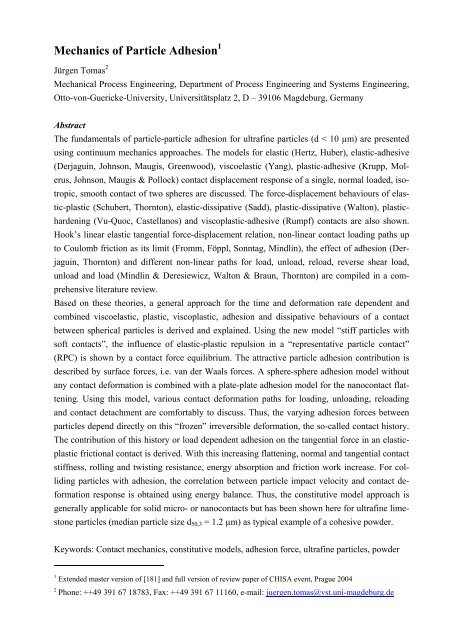
<strong>Mechanics</strong> <strong>of</strong> <strong>Particle</strong> <strong>Adhesion</strong> 1<br />
Jürgen Tomas 2<br />
Mechanical Process Engineering, Department <strong>of</strong> Process Engineering and Systems Engineering,<br />
Otto-von-Guericke-University, Universitätsplatz 2, D – 39106 Magdeburg, Germany<br />
Abstract<br />
The fundamentals <strong>of</strong> particle-particle adhesion for ultrafine particles (d < 10 µm) are presented<br />
using continuum mechanics approaches. The models for elastic (Hertz, Huber), elastic-adhesive<br />
(Derjaguin, Johnson, Maugis, Greenwood), viscoelastic (Yang), plastic-adhesive (Krupp, Mol-<br />
erus, Johnson, Maugis & Pollock) contact displacement response <strong>of</strong> a single, normal loaded, iso-<br />
tropic, smooth contact <strong>of</strong> two spheres are discussed. The force-displacement behaviours <strong>of</strong> elas-<br />
tic-plastic (Schubert, Thornton), elastic-dissipative (Sadd), plastic-dissipative (Walton), plastic-<br />
hardening (Vu-Quoc, Castellanos) and viscoplastic-adhesive (Rumpf) contacts are also shown.<br />
Hook’s linear elastic tangential force-displacement relation, non-linear contact loading paths up<br />
to Coulomb friction as its limit (Fromm, Föppl, Sonntag, Mindlin), the effect <strong>of</strong> adhesion (Der-<br />
jaguin, Thornton) and different non-linear paths for load, unload, reload, reverse shear load,<br />
unload and load (Mindlin & Deresiewicz, Walton & Braun, Thornton) are compiled in a com-<br />
prehensive literature review.<br />
Based on these theories, a general approach for the time and deformation rate dependent and<br />
combined viscoelastic, plastic, viscoplastic, adhesion and dissipative behaviours <strong>of</strong> a contact<br />
between spherical particles is derived and explained. Using the new model “stiff particles with<br />
s<strong>of</strong>t contacts”, the influence <strong>of</strong> elastic-plastic repulsion in a “representative particle contact”<br />
(RPC) is shown by a contact force equilibrium. The attractive particle adhesion contribution is<br />
described by surface forces, i.e. van der Waals forces. A sphere-sphere adhesion model without<br />
any contact deformation is combined with a plate-plate adhesion model for the nanocontact flat-<br />
tening. Using this model, various contact deformation paths for loading, unloading, reloading<br />
and contact detachment are comfortably to discuss. Thus, the varying adhesion forces between<br />
particles depend directly on this “frozen” irreversible deformation, the so-called contact history.<br />
The contribution <strong>of</strong> this history or load dependent adhesion on the tangential force in an elasticplastic<br />
frictional contact is derived. With this increasing flattening, normal and tangential contact<br />
stiffness, rolling and twisting resistance, energy absorption and friction work increase. For colliding<br />
particles with adhesion, the correlation between particle impact velocity and contact deformation<br />
response is obtained using energy balance. Thus, the constitutive model approach is<br />
generally applicable for solid micro- or nanocontacts but has been shown here for ultrafine limestone<br />
particles (median particle size d50,3 = 1.2 µm) as typical example <strong>of</strong> a cohesive powder.<br />
Keywords: Contact mechanics, constitutive models, adhesion force, ultrafine particles, powder<br />
1<br />
Extended master version <strong>of</strong> [ 181]<br />
and full version <strong>of</strong> review paper <strong>of</strong> CHISA event, Prague 2004<br />
2<br />
Phone: ++49 391 67 18783, Fax: ++49 391 67 11160, e-mail: juergen.tomas@vst.uni-magdeburg.de
MECHANICS OF PARTICLE ADHESION .............................................................................1<br />
1. INTRODUCTION.............................................................................................................3<br />
2. PARTICLE ADHESION EFFECTS...............................................................................6<br />
2.1 PARTICLE BOND EFFECTS.............................................................................................................. 6<br />
2.2 COMPARISON BETWEEN DIFFERENT ADHESION FORCES ............................................................ 7<br />
3. PARTICLE CONTACT CONSTITUTIVE MODELS .................................................9<br />
3.1 THE STATE OF ARTS....................................................................................................................... 9<br />
3.2 ELASTIC, PLASTIC AND VISCOPLASTIC CONTACT DEFORMATIONS.......................................... 21<br />
3.2.1 Elastic normal force-displacement function.................................................................................. 21<br />
3.2.2 Elastic-frictional tangential force-displacement function ............................................................. 23<br />
3.2.3 Rolling resistance and elastic-frictional twisting <strong>of</strong> an elastic particle contact............................. 25<br />
3.2.4 Elastic displacement <strong>of</strong> an adhesive contact ................................................................................. 27<br />
3.2.5 Perfect plastic and viscoplastic contact displacement and viscous damping ................................ 31<br />
3.3 LOAD DEPENDENT ADHESION FORCE.......................................................................................... 33<br />
3.3.1 Increase <strong>of</strong> adhesion force by contact consolidation..................................................................... 33<br />
3.3.2 Linear increase <strong>of</strong> adhesion force by normal force ....................................................................... 34<br />
3.3.3 Non-linear increase <strong>of</strong> adhesion force by normal force ................................................................ 35<br />
3.4 VARIATION IN ADHESION DUE TO INELASTIC CONTACT FLATTENING ..................................... 37<br />
3.4.1 Elastic-plastic force-displacement model for loading ................................................................... 37<br />
3.4.2 Unloading and reloading hysteresis and contact detachment........................................................ 40<br />
3.4.3 Viscoplastic contact behaviour and time dependent consolidation............................................... 46<br />
3.5 MEASUREMENT OF ADHESION FORCES ...................................................................................... 48<br />
3.5.1 <strong>Adhesion</strong> effects between particles and surfaces .......................................................................... 48<br />
3.5.2 Principles <strong>of</strong> adhesion force testing methods................................................................................ 49<br />
3.6 ENERGY ABSORPTION IN A CONTACT WITH ADHESION AND PARTICLE IMPACT ..................... 52<br />
3.6.1 Dissipative behaviour <strong>of</strong> contact unload/reload ............................................................................ 52<br />
3.6.2 Elastic particle impact and maximum impact force ...................................................................... 53<br />
3.6.3 Coefficient <strong>of</strong> restitution at particle impact...................................................................................54<br />
3.6.4 <strong>Particle</strong> impact and adhesion, contact displacement and impact force response........................... 56<br />
3.7 REPRESENTATIVE, LOAD DEPENDENT ADHESION FORCE.......................................................... 58<br />
3.7.1 Linear adhesion force – normal force function ............................................................................. 58<br />
3.7.2 <strong>Adhesion</strong> force <strong>of</strong> a stiff contact with surface asperity ................................................................. 60<br />
3.7.3 Non-linear adhesion force – normal force function ...................................................................... 63<br />
3.7.4 Elastic-plastic, frictional tangential force <strong>of</strong> load dependent adhesion contact ............................ 65<br />
3.7.5 Elastic-plastic, frictional rolling resistance <strong>of</strong> load dependent adhesion contact .......................... 68<br />
3.7.6 Elastic-plastic, frictional twisting <strong>of</strong> load dependent adhesion contact......................................... 71<br />
4. CONTACT FAILURE BY SHEAR AND POWDER YIELD ....................................73<br />
5. CONCLUSIONS..............................................................................................................78<br />
<strong>Mechanics</strong>_<strong>Particle</strong>_<strong>Adhesion</strong>_full.doc © <strong>Mechanics</strong> <strong>of</strong> <strong>Particle</strong> <strong>Adhesion</strong> Pr<strong>of</strong>. Dr. J. Tomas 09.01.2006<br />
2
ACKNOWLEDGEMENTS........................................................................................................79<br />
SYMBOL, UNIT, DESCRIPTION ......................................................................................79<br />
INDICES ......................................................................................................................................81<br />
REFERENCES............................................................................................................................83<br />
1. Introduction<br />
In particle processing and product handling <strong>of</strong> fine (d < 100 µm), ultrafine (d < 10 µm) and<br />
nanosized particles (d < 0.1 µm), the well-known flow problems <strong>of</strong> cohesive powders in process<br />
apparatuses or storage and transportation containers include bridging, channelling, widely spread<br />
residence time distribution associated with time consolidation or caking effects, chemical con-<br />
versions and deterioration <strong>of</strong> bioparticles. Avalanching effects and oscillating mass flow rates in<br />
conveyors lead to feeding and dosing problems. Finally, insufficient apparatus and system reli-<br />
ability <strong>of</strong> powder processing plants are also related to these flow problems.<br />
The rapid increasing production <strong>of</strong> cohesive to very cohesive ultrafine to nanosized powders [1],<br />
e.g. pigment particles, toner, pharmaceuticals, micro-carriers in biotechnology or medicine, aux-<br />
iliary materials in catalysis, chromatography or silicon wafer polishing, make these problems<br />
much more serious. Taking into account this list <strong>of</strong> adhesion effects, technical problems and haz-<br />
ards in processing units, it is essential to deal with the fundamentals <strong>of</strong> particle adhesion, powder<br />
consolidation, compaction and flow, i.e. to develop a reasonable combination <strong>of</strong> particle and<br />
continuum mechanics, Fig. 1.<br />
In terms <strong>of</strong> powder mechanics (see level I), the well-known failure hypotheses <strong>of</strong> Tresca, Cou-<br />
lomb-Mohr and Drucker-Prager (in [2 - 5]), the yield locus concepts <strong>of</strong> Jenike [6, 7] and<br />
Schwedes [8, 9], the Warren-Spring equations [10 - 14] and the approach by Tüzün [16, 17] were<br />
supplemented by Molerus [18 - 21] to describe the cohesive, steady-state powder flow criterion.<br />
Forces acting on particles under stress in a regular assembly and its dilatancy were considered by<br />
Rowe [22] and Horne [23]. Savage and Sayed [24], Johnson and Jackson [25], Nedderman [26,<br />
27], Satake and Jenkins [28] have modelled the rapid and collisional flow <strong>of</strong> non-adhering parti-<br />
cles. Moreau [29], Bagi [30, 31], Kruyt [32, 33], Goddard [34], Satake [35], Kaneko et al. [36],<br />
Goldhirsch [37], Radjai [38] and others described the micromechanics <strong>of</strong> granular media. Tardos<br />
[39] discussed the frictional flow for compressible powders without any cohesion from the fluid<br />
mechanics point <strong>of</strong> view.<br />
Moreover, modelling and simulation <strong>of</strong> particle dynamics <strong>of</strong> free flowing granular media is in-<br />
creasingly used, see e.g. Deresiewicz [40], Cundall [41], Campbell [42], Walton [43, 44], Duran<br />
[45], Herrmann [46, 47], Thornton [48], Luding [49, 50] and Wolf [51 - 53].<br />
The fundamentals <strong>of</strong> contact mechanics and impact mechanics are compiled and described by<br />
Johnson [54] and Stronge [55]. Multibody dynamics, their contacts and finite element modelling<br />
are shown by Eberhard [56].<br />
<strong>Mechanics</strong>_<strong>Particle</strong>_<strong>Adhesion</strong>_full.doc © <strong>Mechanics</strong> <strong>of</strong> <strong>Particle</strong> <strong>Adhesion</strong> Pr<strong>of</strong>. Dr. J. Tomas 09.01.2006<br />
3
The fundamentals <strong>of</strong> molecular attraction potentials and the mechanics <strong>of</strong> adhesion are treated<br />
for example by Krupp [57], Johnson [54], Israelachvili [58], Maugis [59] and Kendall [60].<br />
Fig. 1: Hierarchy <strong>of</strong> the dynamics <strong>of</strong> random packing in particle beds, clusters or agglomerates<br />
(fixed spatial coordinates x1, x2, x3, i,j = 1, 2, 3; normal stresses σii and shear stresses σij, compression<br />
vii and shear rates vij, normal strains εii, distortions εij, stress increments ∆σij and dσij).<br />
I. Level <strong>of</strong> Continuum <strong>Mechanics</strong>: 3-dimensional continuum models described by tensor<br />
equations (2 nd order vectors) <strong>of</strong> representative volume elements (RVE). This includes<br />
balances for mass (continuity), forces, momentum (impulse), moment (torque) and energy<br />
for 3 translational and 3 rotational degrees <strong>of</strong> freedom.<br />
II. Level <strong>of</strong> Micromechanics: Macro – microtransition to a representative, geometrically<br />
equivalent, 2-dimensional plane element with a finite number <strong>of</strong> discrete sub-elements,<br />
i.e. particles. All the particle interactions inside <strong>of</strong> a random packing structure are described<br />
by contact forces (1 st order vectors) in normal and tangential direction with fundamental<br />
laws for elastic force-displacement relations, inelastic deformations (plastic dislocations),<br />
solid friction and viscous damping – see the typical symbols <strong>of</strong> spring, Coulomb-friction<br />
and dashpot elements in the circular detail.<br />
III. Level <strong>of</strong> Molecular Dynamics: Dominant molecular interactions at particle contact surfaces.<br />
All the mentioned mechanical properties are influenced by surface properties, e.g.<br />
adsorbed layers <strong>of</strong> condensed matter (adsorbed moisture, electrostatic bilayers or surfactants).<br />
Generally, fundamental material properties as elasticity, bonding strength, viscosity<br />
(rate dependent stiffness), electromagnetic, thermal and mechanical wave propagation<br />
characteristics or phase conversion enthalpies can be physically explained by these molecular<br />
interaction energies and potential forces and simulated by molecular dynamics.<br />
<strong>Mechanics</strong>_<strong>Particle</strong>_<strong>Adhesion</strong>_full.doc © <strong>Mechanics</strong> <strong>of</strong> <strong>Particle</strong> <strong>Adhesion</strong> Pr<strong>of</strong>. Dr. J. Tomas 09.01.2006<br />
4
In particle technology, adhesion effects are related to undesired powder blocking at conveyor<br />
transfer chutes [61], in pneumatic pipe bends [62], to fluidization problems in handling [63], to<br />
desired particle cake formation on filter media [64, 65] or to pigment adhesion. The caking <strong>of</strong><br />
food [66, 67], toner handling [68], wear effects <strong>of</strong> adhering solid surfaces [69, 70], fouling at<br />
heat exchangers [71] or in membrane filters [72], thermal conductivity in particle beds [73, 74],<br />
fine particle deposition in lungs, formulation <strong>of</strong> particulate products, particle coating, powder<br />
tabletting and briquetting, and the granulate strength [75 - 86] or surface cleaning <strong>of</strong> silicon wa-<br />
fers [87 - 95], etc., are also connected with adhesion - desired or undesired. <strong>Adhesion</strong> and fric-<br />
tion is also an serious problem dealt in tribology [15, 16].<br />
First, the essential particle bond effects are introduced and compared in chapter 2. In the main<br />
chapter 3, after a comprehensive literature review 3.1, the elastic, plastic and viscoplastic force –<br />
displacement models are explained in section 3.2. Then the problem <strong>of</strong> load dependent adhesion<br />
force is treated by reviewing the literature, section 3.3. Because <strong>of</strong> essential problems related to<br />
ultrafine particles the elastic-plastic yield and adhesion limits <strong>of</strong> contact flattening are derived as<br />
quasi-static problems in section 3.4. Measurements, energy balances and impact problems <strong>of</strong><br />
rapid moving particles are treated in sections 3.5 and 3.6. The consequences for the representa-<br />
tive load dependent adhesion force with respect to contact sliding, particle rolling and torsion,<br />
Fig. 2, can be read in section 3.7. How to apply these contact laws to model the consolidation<br />
and frictional shear flow <strong>of</strong> ultrafine cohesive powders, i.e. for applications in powder process-<br />
ing, storage and handling, is seen in chapter 4.<br />
Fig. 2: <strong>Particle</strong> contact forces, moments and degrees <strong>of</strong> freedom: one normal load or central impact<br />
in direction <strong>of</strong> principal axis and one torsional moment around this axis, two tangential<br />
forces and two rolling moments within the plane <strong>of</strong> flattened contact and their respectice constitutive<br />
force – displacement and moment – angle relations.<br />
<strong>Mechanics</strong>_<strong>Particle</strong>_<strong>Adhesion</strong>_full.doc © <strong>Mechanics</strong> <strong>of</strong> <strong>Particle</strong> <strong>Adhesion</strong> Pr<strong>of</strong>. Dr. J. Tomas 09.01.2006<br />
5
2. <strong>Particle</strong> adhesion effects<br />
2.1 <strong>Particle</strong> bond effects<br />
<strong>Particle</strong> adhesion can be explained by following bond effects, Fig. 3, [75 - 81, 96 - 100]:<br />
Fig. 3: <strong>Particle</strong> adhesion and microprocesses <strong>of</strong> particle bond effects in contact:<br />
- Surface and field forces at direct contact:<br />
• Van der Waals forces,<br />
• Electrostatic forces,<br />
� electric conductor,<br />
� electric non-conductor,<br />
• Magnetic force;<br />
- Material bridges between particle surfaces:<br />
• Hydrogen bonds <strong>of</strong> adsorbed surface layers <strong>of</strong> condensed water,<br />
• Organic macromolecules as flocculants in suspensions;<br />
• Liquid bridges <strong>of</strong><br />
� Low viscous wetting liquids by capillary pressure and surface tension,<br />
� High viscous bond agents (resins);<br />
• Solid bridges by<br />
<strong>Mechanics</strong>_<strong>Particle</strong>_<strong>Adhesion</strong>_full.doc © <strong>Mechanics</strong> <strong>of</strong> <strong>Particle</strong> <strong>Adhesion</strong> Pr<strong>of</strong>. Dr. J. Tomas 09.01.2006<br />
6
� Recrystallisation <strong>of</strong> liquid bridges which contains solvents (salt),<br />
� Solidification <strong>of</strong> swelled ultrafine sol particles (starch, clay),<br />
� Freezing <strong>of</strong> liquid bridge bonds,<br />
� Chemical reactions with adsorbed surface layers (cement hydration by water),<br />
� Solidification <strong>of</strong> high viscous bond agents (asphalt),<br />
� Contact fusion by sintering (aggregates <strong>of</strong> nanoparticles),<br />
� Chemical bonds by solid-solid reactions (glass batch);<br />
- interlocking by macromolecular and particle shape effects;<br />
• Interlocking <strong>of</strong> chain branches at macromolecules (proteins),<br />
• Interlocking <strong>of</strong> contacts by overlaps <strong>of</strong> surface roughness,<br />
• Interlocking by hook-like bonds.<br />
These bond effects are directly related to the micromechanical level II and III explained before.<br />
2.2 Comparison between different adhesion forces<br />
The strength <strong>of</strong> different adhesion effects is compared in Fig. 4. Disregarding the solid bridge<br />
bonds [96 - 98, 159, 328], the liquid bridge is the dominating adhesion force [77], as long as the<br />
liquid bridge is formed, see e.g. Tomas [96], Schubert [101], Adams [102], Ennis [103] or<br />
Seville [104].<br />
a) Smooth sphere - smooth plate (equivalent to coarse particle<br />
with very large radius <strong>of</strong> surface curvature)<br />
adhesion force F H0 in N<br />
a 0<br />
10 -5<br />
10 -6<br />
10 -7<br />
10 -8<br />
10 -9<br />
α<br />
d<br />
2<br />
weight <strong>of</strong> sphere<br />
10 -1 1 10 10 2 10 3<br />
particle size d in µm<br />
adhesion force F H0 in nN<br />
10 4<br />
10 2<br />
1<br />
10 -2<br />
10 -4<br />
α = 20°<br />
liquid bridge<br />
rel. humidity 50%<br />
van der Waals<br />
a 0 = 0.4 nm<br />
10 -1 1 10 10 2 10 3<br />
particle separation a in nm<br />
x<br />
adhesion force F H0 in N<br />
h r<br />
a 0<br />
10 -5<br />
10 -6<br />
10 -7<br />
10 -8<br />
10 -9<br />
d<br />
2<br />
liquid bridge, d = 1<br />
1 10 10 2 10 3<br />
roughness height 2 . h r in nm<br />
7<br />
b) Rough sphere (hemispherical<br />
roughness) - smooth plate<br />
Fig. 4: <strong>Adhesion</strong> forces between stiff particle and smooth surface according to Rumpf [77], calculated<br />
with a0 = 0.4 nm molecular centre separation (at interaction force equilibrium), α = 20°<br />
bridge angle, θ = 0° wetting angle, σlg = 72 mJ/m² surface tension <strong>of</strong> water, CH = 19 . 10 -20 J<br />
Hamaker constant acc. to Lifshitz, qma = 16 . 10 -18 As/µm² surface charge density, U = 0.5 V con-<br />
tact potential, ( ) 2<br />
= C − C<br />
C Hamaker constant for particle-water-particle interaction.<br />
H,<br />
sls<br />
H,<br />
ss<br />
H,<br />
ll<br />
conductor<br />
non-conductor<br />
non-conductor, d = 10 µm<br />
Instead <strong>of</strong> the smooth plate one can also consider a coarse smooth particle with a large radius <strong>of</strong><br />
surface curvature.<br />
<strong>Mechanics</strong>_<strong>Particle</strong>_<strong>Adhesion</strong>_full.doc © <strong>Mechanics</strong> <strong>of</strong> <strong>Particle</strong> <strong>Adhesion</strong> Pr<strong>of</strong>. Dr. J. Tomas 09.01.2006<br />
con u
Without the liquid bridge, the van der Waals force <strong>of</strong> a dry contact dominates at fine particles.<br />
This van der Waals force can be considerably decreased in wet environment because <strong>of</strong> the re-<br />
duction <strong>of</strong> Hamaker constant by the interstitial water. This effect is widely used in washing proc-<br />
esses. For charged particles such as toner particles the Coulomb force becomes important. The<br />
surface-charge density is assumed to be qmax = 16 . 10 -18 As/µm² which is the maximum value<br />
determined by the electric field limit for discharging. Sometimes the Coulomb force may be lar-<br />
ger than the van der Waals force because the maximum surface-charge density is determined by<br />
the voltage limit rather than the field limit [105].<br />
In the above discussion, the effects <strong>of</strong> the atmospheric conditions are not taken into considera-<br />
tion. Because <strong>of</strong> humidity <strong>of</strong> the ambient air water is adsorbed at particle surfaces. These surface<br />
layers <strong>of</strong> condensed water increase remarkably the effective contact zone. By molecular bonds<br />
between these condensed liquid molecules (known as surface tension), these surface layers may<br />
form additionally small liquid bridges which results in the alternation <strong>of</strong> the adhesion force [75,<br />
106]. The humidity also changes the adsorbed water layer thickness, see e.g. [106 - 97], and it<br />
also affects the adhesion force. Thus, the adhesion is influenced by mobile adsorption layers due<br />
to molecular rearrangement and additional hydrogen bonds [100].<br />
As long as the liquid bridge is stable, the critical separation for rupture is about<br />
a ≈<br />
[107], the separation influences hardly the bond force. Van der Waals forces and Coulomb forces<br />
(for a conductor) have equivalent long-range force-separation (distance) curves FH0(a), Fig. 4<br />
middle panel. The Coulomb forces <strong>of</strong> a non-conductor do not depend on separation. This is<br />
widely used to precipitate dust particles in an electric field.<br />
The effect <strong>of</strong> van der Waals forces strongly depends on the roughness <strong>of</strong> a surface, Fig. 4 panel<br />
b). Minimum <strong>of</strong> van der Waals force is seen versus roughness height hr for different particle<br />
sizes d. The influence <strong>of</strong> roughness for liquid bridge bonds and adsorption layers (humidity) is<br />
comparatively small. The adhesion will also be affected by temperature [105]. It is worth to note<br />
here that the weight <strong>of</strong> fine particles (d < 100 µm) is very small compared to the adhesion forces<br />
which dominate particle interaction in the gravitational field.<br />
The force-displacement behaviours <strong>of</strong> elastic, elastic-adhesive, plastic-adhesive, elastic-plastic,<br />
elastic-dissipative, plastic-dissipative and viscoplastic-adhesive contacts are shown. Based on<br />
these individual theories, a general approach for the time and deformation rate dependent and<br />
combined viscoelastic, plastic, viscoplastic, adhesion and dissipative behaviours <strong>of</strong> a contact<br />
between spherical particles is derived and explained. We focus here on the adhesion forces at<br />
particle contacts which are necessary to understand physically the consolidation and non-rapid<br />
flow <strong>of</strong> more or less dry, fine, ultrafine down to nanoscaled cohesive powders (particle size d <<br />
100 µm).<br />
<strong>Mechanics</strong>_<strong>Particle</strong>_<strong>Adhesion</strong>_full.doc © <strong>Mechanics</strong> <strong>of</strong> <strong>Particle</strong> <strong>Adhesion</strong> Pr<strong>of</strong>. Dr. J. Tomas 09.01.2006<br />
crit<br />
3<br />
V<br />
8<br />
l
3. <strong>Particle</strong> contact constitutive models<br />
3.1 The state <strong>of</strong> arts<br />
An appropriate introduction in contact mechanics one can find at Fischer-Cripps [5] with respect<br />
to the fundamentals <strong>of</strong> engineering mechanics. Moreover, for particle technology, powder proc-<br />
essing and handling, in principle, there are four essential deformation effects in particle-surface<br />
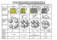
contacts and their force-response (stress-strain) behaviours can be explained as follows, Table 1:<br />
(1) elastic contact deformation (Hertz [108], Huber [109], Derjaguin [110], Bradley [112],<br />
Fromm [113], Cattaneo [114], Föppl [115], Sonntag [116], Mindlin [117], Deresiewicz [122],<br />
Lurje [123], Sperling [124], Krupp [57], Greenwood [125], Johnson [126], Dahneke [127],<br />
Maw [129], Tsai [130], Thornton [131, 132], Sadd [133], Tavares [134], Vu-Quoc [135] or Di<br />
Renzo [141]) which is reversible, independent <strong>of</strong> deformation rate and consolidation time ef-<br />
fects and valid for all particulate solids;<br />
(2) plastic contact deformation with adhesion (Derjaguin [110], Krupp [142], Greenwood [125],<br />
Schubert [143], Molerus [18, 19], Maugis [144], Walton [145], Fleck [146], Greenwood<br />
[147], Thornton [150, 151], Tomas [152 - 155], Vu-Quoc [136, 139], Mesarovic & Johnson<br />
[156], Luding [157, 158], Delenne [159], Martin [160] or Castellanos [161]) which is irre-<br />
versible, deformation rate and consolidation time independent, e.g. mineral or metal powders;<br />
(3) viscoelastic contact deformation (Pao [162], Lee [163], Hunter [164], Yang [165], Krupp<br />
[57], Rumpf [166], Stieß [167], Walton [44], Sadd [133], Scarlett [169], Leszczynski [170] or<br />
Brilliantov [172]) which is reversible and dependent on deformation rate and consolidation<br />
time, e.g. plastics, s<strong>of</strong>t organic chemicals or bio-particles;<br />
(4) viscoplastic contact deformation (Rumpf [166], Stieß [167], Kuhn [168], Bouvard [173],<br />
Storakers [174, 175], Parhami [176, 177], Tomas [178 - 181], Fleck [182], McMeeking [183],<br />
Tomas [184, 185] or Luding [186]) which is irreversible and dependent on deformation rate<br />
and consolidation time, e.g. nanoparticles fusion.<br />
In terms <strong>of</strong> simulations <strong>of</strong> particle dynamics by discrete element method the commonly used<br />
linear spring-dashpot model [41, 191] was extended according to viscous damping by Pöschel et<br />
al. [193], for plasticity by Luding [157, 158] and for liquid bridge bonds by Thornton [107] and<br />
Gröger [196, 197].<br />
<strong>Mechanics</strong>_<strong>Particle</strong>_<strong>Adhesion</strong>_full.doc © <strong>Mechanics</strong> <strong>of</strong> <strong>Particle</strong> <strong>Adhesion</strong> Pr<strong>of</strong>. Dr. J. Tomas 09.01.2006<br />
9
Table 1: <strong>Particle</strong> contact models for smooth spheres on the basis <strong>of</strong> continuum approaches<br />
authors assumptions characteristic force-displacement or adhesion force models contact area and characteristic diagrams<br />
Hertz [108]<br />
1882<br />
Huber [109]<br />
1904<br />
Fromm [113]<br />
1927<br />
Föppl [115]<br />
1936/1947 and<br />
Sonntag [187]<br />
1950<br />
elastic behaviour,<br />
normal force FN<br />
elastic behaviour,<br />
principal stresses<br />
elastic rolling<br />
disks, no-slip and<br />
partial-slip<br />
elastic rolling, no-<br />
slip, partial-slip,<br />
friction,<br />
⎛<br />
⎜<br />
⎝<br />
p<br />
⎞<br />
⎟<br />
2<br />
⎛<br />
⎜<br />
r<br />
⎞<br />
⎟<br />
2<br />
3⋅<br />
F<br />
el<br />
K<br />
N<br />
1<br />
p ⎟ = −<br />
⎜<br />
max r ⎟<br />
with pmax<br />
=<br />
p<br />
2<br />
⎠ ⎝ K,<br />
el ⎠<br />
2⋅<br />
π⋅<br />
rK,<br />
el<br />
2<br />
3<br />
N = ⋅E<br />
* ⋅ r1,<br />
2 h<br />
pressure<br />
K<br />
rK,el F ⋅<br />
3<br />
σ y ( rK<br />
) 1−<br />
2⋅<br />
ν r<br />
= − ⋅<br />
p 3<br />
max<br />
max<br />
2<br />
K,<br />
el<br />
2<br />
rK<br />
σ y ( rK<br />
) 1−<br />
2⋅<br />
ν r<br />
= − ⋅<br />
p 3<br />
2<br />
K,<br />
el<br />
2<br />
rK<br />
3/<br />
2<br />
⎡ ⎛ 2<br />
2<br />
r ⎞ ⎤<br />
K<br />
rK<br />
⋅ ⎢1−<br />
⎜1<br />
⎟ ⎥ + 1−<br />
2<br />
2<br />
⎢ ⎜<br />
−<br />
for rK ≤ rK,el<br />
r ⎟<br />
K,<br />
el ⎥ rK,<br />
el<br />
⎣ ⎝ ⎠ ⎦<br />
for rK,el ≤ principal<br />
rK<br />
2<br />
⎡ ⎛ E*<br />
⎞ ⎤<br />
F ⎢ ⎜<br />
⎟ ⎥<br />
T = µ i ⋅ FN<br />
⋅ 1−<br />
⎢<br />
⎜<br />
⋅δ<br />
⎟<br />
slide:<br />
⎥<br />
⎣ ⎝ 4⋅<br />
µ i ⋅ pmax,<br />
disk ⋅ bK,<br />
el ⎠ ⎦<br />
with<br />
p<br />
2⋅<br />
F<br />
N<br />
max, disk = and<br />
π⋅<br />
l ⋅ bK,<br />
el<br />
b<br />
K,<br />
el<br />
=<br />
8⋅<br />
r<br />
1,<br />
2<br />
⋅ F<br />
N<br />
π⋅<br />
l ⋅ E*<br />
5 / 2<br />
⎡ ⎛ 2⋅<br />
E*<br />
⋅r<br />
⎞ ⎤<br />
K,<br />
el<br />
F = µ ⋅ ⋅ ⎢ −<br />
⎜ − ⋅δ<br />
⎟<br />
T i FN<br />
1 1<br />
⎥ sliding at rolling<br />
⎢⎣<br />
⎝ 3⋅<br />
µ i ⋅ FN<br />
⎠ ⎥⎦<br />
∆vϕ<br />
∆ω<br />
δ<br />
= ≈<br />
v ω<br />
ϕ<br />
bK,<br />
el<br />
stress σ y<br />
- tension<br />
p max<br />
0<br />
+ pressure<br />
shear stress τ<br />
x<br />
no-<br />
slip<br />
slip 0<br />
2 . r K,b<br />
<strong>Mechanics</strong>_<strong>Particle</strong>_<strong>Adhesion</strong>_full.doc © <strong>Mechanics</strong> <strong>of</strong> <strong>Particle</strong> <strong>Adhesion</strong> Pr<strong>of</strong>. Dr. J. Tomas 09.01.2006<br />
r K,el<br />
b K,slip<br />
b K,el<br />
y<br />
0<br />
rolling<br />
contact<br />
plane<br />
stress σy - tension<br />
radius r K<br />
0<br />
rolling<br />
force F N<br />
bK bK,el displacement h K<br />
(1/2+ν) . p max<br />
2 . r K,b<br />
r K,el<br />
tangential<br />
force FT x<br />
-(1/3-2 . ν/3) . p max<br />
F T=µ i . FN<br />
displacement δ<br />
press<br />
+ roll<br />
r<br />
K,el<br />
0 x<br />
- 20/9 . µ R . pmax<br />
10
Cattaneo [114]<br />
1938 and<br />
Mindlin [117]<br />
1949<br />
Mindlin and<br />
Deresiewicz<br />
[118] 1953<br />
Lubkin [119]<br />
1951, Cattaneo<br />
[120] 1952 and<br />
Deresiewicz<br />
[122] 1954<br />
Sonntag [116]<br />
1949, Hamilton<br />
[188] 1966<br />
elastic behaviour,<br />
tangential slip FT,<br />
shear stress by<br />
sliding τ and tor-<br />
sion τto<br />
elastic behaviour,<br />
tangential unload<br />
and reload hys-<br />
teresis<br />
Elastic-frictional<br />
twisting, unload,<br />
reload hystereses<br />
elastic sliding<br />
spheres,<br />
F 4⋅<br />
G * ⋅r<br />
⋅δ<br />
for elastic no-slip,<br />
T = K<br />
3⋅<br />
µ ⋅ F<br />
δ =<br />
8⋅<br />
G * ⋅r<br />
3⋅<br />
µ ⋅ F<br />
i N 1<br />
K,<br />
el<br />
⋅<br />
⎡ ⎛ F ⎞ T<br />
⋅ ⎢ −<br />
⎜<br />
⎜1−<br />
⎟<br />
⎢ ⎝ µ i ⋅ FN<br />
⎣<br />
⎠<br />
2 / 3<br />
⎤<br />
⎥<br />
⎥⎦<br />
τ<br />
2 2 ⎛ F ⎞ T<br />
r = ⋅<br />
⎜ −<br />
⎟<br />
K,<br />
slip rK,<br />
el 1 ,<br />
⎝ µ i ⋅ FN<br />
⎠<br />
to<br />
3⋅<br />
M<br />
=<br />
4⋅<br />
π⋅<br />
⋅ y ⎛ r<br />
⋅⎜<br />
⎜<br />
1−<br />
⎝ r<br />
to<br />
4<br />
rK,<br />
el<br />
2 2 ( 1−<br />
rK<br />
/ rK,<br />
el −<br />
2 2 2<br />
rK,<br />
slip / rK,<br />
el − rK<br />
/<br />
2<br />
K,<br />
el )<br />
2 ( 1−<br />
rK<br />
/<br />
2<br />
K,<br />
el )<br />
2<br />
K<br />
2<br />
K,<br />
el<br />
i N τ =<br />
r rK ≤ rK,slip<br />
2<br />
2⋅<br />
π⋅<br />
rK,<br />
el<br />
3⋅<br />
µ ⋅ F<br />
τ = ⋅<br />
partial-slip: rK,slip ≤ rK ≤ rK,el<br />
2⋅<br />
π<br />
3⋅<br />
µ i ⋅ F<br />
δ = ±<br />
8⋅<br />
G * ⋅r<br />
Gr<br />
r<br />
2<br />
K,<br />
el<br />
2µ<br />
F<br />
i<br />
⋅ φ<br />
N<br />
K,<br />
counterslip<br />
i N r<br />
2<br />
⋅ rK,<br />
el<br />
= ±<br />
r<br />
=<br />
N<br />
K,<br />
el<br />
⎡ ⎛ FT<br />
, U m F<br />
⋅ ⎢2⋅<br />
⎜<br />
⎜1−<br />
⎢⎣<br />
⎝ 2⋅<br />
µ i ⋅ F<br />
* ( M m M )<br />
3 to 1−<br />
4µ<br />
F<br />
K,<br />
el<br />
3<br />
⋅<br />
i<br />
N<br />
r<br />
to<br />
K,<br />
el<br />
T<br />
N<br />
⎞<br />
⎟<br />
⎠<br />
2 / 3<br />
⎛ FT<br />
, U<br />
−<br />
⎜<br />
⎜1−<br />
⎝ µ i ⋅ F<br />
N<br />
⎞<br />
⎟<br />
⎠<br />
1 ⎡ 3⋅<br />
M<br />
m ⎢1<br />
+ 1−<br />
2 ⎢⎣<br />
2µ<br />
iFN<br />
r<br />
1/<br />
2<br />
* ( M to − M to ) ⎞<br />
⎟ −1<br />
⎛ 3<br />
4 ⎜<br />
⋅<br />
⋅<br />
⎜<br />
1−<br />
⎝ 4 ⋅ µ i ⋅ FN<br />
⋅ r<br />
K,<br />
el<br />
3⋅<br />
F ⎡ N<br />
y = ⋅ ⎢2νC0<br />
+<br />
3<br />
2⋅<br />
π⋅<br />
rK,<br />
el ⎣<br />
⎛ C<br />
2<br />
2y<br />
C<br />
3⋅<br />
F ⎡<br />
⎤<br />
N xyC0<br />
2xyC1<br />
= ⋅ ⎢ − 2 ⎥ for rK < rK,el<br />
3<br />
2⋅<br />
π⋅<br />
rK,<br />
el ⎣ rK<br />
rK<br />
⎦<br />
⎟<br />
⎠<br />
2 / 3<br />
*<br />
to<br />
K,<br />
el<br />
⎞⎤<br />
1<br />
1 0<br />
( 1−<br />
2ν)<br />
⎜ − + ⎟<br />
2 4 ⎥<br />
⎝ rK<br />
rK<br />
rK<br />
⎠⎦<br />
σ 2<br />
τ 4<br />
y<br />
2<br />
C<br />
⎤<br />
−1⎥<br />
⎥⎦<br />
⎞<br />
⎟<br />
⎠<br />
−1/<br />
2<br />
⎤ 3⋅<br />
M<br />
⎥ −<br />
⎥⎦<br />
16µ<br />
iFN<br />
r<br />
to<br />
K,<br />
el<br />
r K,el<br />
r K,el<br />
contact plane<br />
stress σy shear<br />
stress τ<br />
<strong>Mechanics</strong>_<strong>Particle</strong>_<strong>Adhesion</strong>_full.doc © <strong>Mechanics</strong> <strong>of</strong> <strong>Particle</strong> <strong>Adhesion</strong> Pr<strong>of</strong>. Dr. J. Tomas 09.01.2006<br />
shear<br />
stress τ<br />
0<br />
0<br />
r K,el<br />
r K,slip<br />
y<br />
z<br />
r K,slip<br />
r K,slip<br />
0<br />
τ=µ i . σ<br />
r K<br />
r K<br />
τ=µ i . p(rK)<br />
M to<br />
φ<br />
-δ U<br />
r K<br />
x<br />
tangential force F T<br />
F T,U<br />
F T<br />
-M* to<br />
-φ∗<br />
F T=µ i . FN<br />
δ C<br />
displacement δ<br />
-F T,U<br />
M* to<br />
M to<br />
sliding press<br />
+ slide<br />
r<br />
K,el<br />
0 x<br />
δ U<br />
⎡1−<br />
2 ⋅ ν π ⋅µ<br />
i ⎛ ν ⎞⎤<br />
- tension − pmax<br />
⋅ ⎢ + ⋅⎜1<br />
+ ⎟⎥<br />
⎣ 3 2 ⎝ 4 ⎠⎦<br />
δ<br />
F T=-µ i . FN<br />
φ∗<br />
M to,C<br />
φ<br />
M to,C=-2/3 . µ i . FN . rK,el<br />
11
Yang [165]<br />
1966<br />
Johnson, Kend-<br />
all and Roberts<br />
[126] 1971<br />
Dahneke [127]<br />
1972<br />
Derjaguin [110]<br />
1934, Muller<br />
and Toporov<br />
[128] 1975<br />
Molerus [18,<br />
19] 1975/78<br />
viscoelastic re-<br />
laxation, normal<br />
force<br />
elastic behaviour,<br />
normal force, con-<br />
stant adhesion<br />
elastic behaviour,<br />
normal force,<br />
varying adhesion<br />
elastic behaviour,<br />
normal force, con-<br />
stant adhesion FH0<br />
perfect plastic<br />
behaviour, varying<br />
van der Waals<br />
adhesion, shearing<br />
r<br />
3<br />
K<br />
3⋅<br />
r ⎡<br />
1,<br />
2 ⋅FN<br />
=<br />
⋅<br />
* ⎢<br />
2⋅<br />
E 0 ( t = 0)<br />
⎣E<br />
H,<br />
JKR<br />
1,<br />
2<br />
ss<br />
*<br />
∞<br />
*<br />
E ⎛ 0 E<br />
+ ⎜<br />
⎜1−<br />
( t → ∞)<br />
⎝ E<br />
*<br />
0<br />
*<br />
∞<br />
⎞<br />
⎤<br />
⎟<br />
⎟⋅<br />
exp(<br />
− t t relax )⎥<br />
⎠<br />
⎦<br />
p<br />
3 3⋅<br />
r1,<br />
2 ⎛<br />
2 ⎞<br />
rK<br />
= ⋅⎜<br />
FN<br />
+ FH<br />
, JKR + 2⋅<br />
FH<br />
, JKR ⋅FN<br />
+ FH<br />
, JKR ⎟<br />
2⋅<br />
E*<br />
⎝<br />
⎠<br />
F = 6⋅<br />
π⋅<br />
r ⋅σ<br />
pressure<br />
F<br />
F<br />
H<br />
= F<br />
H,<br />
max<br />
H0<br />
CH<br />
⋅ r1,<br />
2 ⎛ 2⋅<br />
h<br />
+ A ⋅ = ⋅<br />
⎜<br />
K pVdW<br />
1+<br />
2<br />
6⋅<br />
a 0 ⎝ a 0<br />
2<br />
C ⎛<br />
⎞<br />
H ⋅r1<br />
, 2 2⋅<br />
CH<br />
⋅r1<br />
, 2<br />
⋅⎜<br />
⎟<br />
⎜<br />
1+<br />
2<br />
2<br />
6⋅<br />
a<br />
⎟<br />
0 ⎝ 27⋅<br />
E*<br />
⋅a<br />
0 ⎠<br />
= 7<br />
⎛ σss<br />
⎞<br />
FH<br />
0 = 4⋅<br />
π⋅<br />
r1,<br />
2 ⋅⎜<br />
σsg<br />
− ⎟<br />
⎝ 2 ⎠<br />
FN ⎛ σss<br />
⎞ 2<br />
2⋅<br />
π⋅<br />
r1,<br />
2 ⋅⎜<br />
σsg<br />
− ⎟ = ⋅E<br />
* ⋅<br />
⎝ 2 ⎠ 3<br />
r1,<br />
2 ⋅h<br />
+ pressure p<br />
p<br />
F ⋅<br />
VdW<br />
T<br />
H = FH<br />
0 + ⋅FN<br />
= FH<br />
0 + κp<br />
FN<br />
slip at ≤ µ i = tan ϕi<br />
pf<br />
FN<br />
K<br />
⎞<br />
⎟<br />
⎠<br />
3<br />
K<br />
F<br />
∑<br />
r K,v,el<br />
r K,el<br />
r K,el<br />
r K,el<br />
pressure p<br />
p<br />
p<br />
0<br />
p max<br />
0<br />
p max<br />
p max<br />
0<br />
p max=p f<br />
<strong>Mechanics</strong>_<strong>Particle</strong>_<strong>Adhesion</strong>_full.doc © <strong>Mechanics</strong> <strong>of</strong> <strong>Particle</strong> <strong>Adhesion</strong> Pr<strong>of</strong>. Dr. J. Tomas 09.01.2006<br />
r K,pl<br />
0<br />
0<br />
t=0<br />
p max<br />
r K<br />
r K<br />
t>0<br />
adhesion force F H<br />
r K<br />
r K<br />
r K,el<br />
F H0<br />
0<br />
force F N<br />
0<br />
F H0<br />
force F N<br />
force F N<br />
t=0<br />
t>0<br />
displacement h K<br />
0<br />
F H,JKR<br />
0<br />
radius rK displacement h K<br />
displacement h K<br />
force F N<br />
h K<br />
displacement h K<br />
12
Schubert et al.<br />
[143] 1976<br />
Rumpf et al.<br />
[166] 1976<br />
Rumpf et al.<br />
[166] 1976<br />
Stieß [167]<br />
1976<br />
Savkoor and<br />
Briggs [189]<br />
1977<br />
elastic-plastic be-<br />
haviour, varying<br />
van der Waals<br />
adhesion force FH<br />
viscoelastic be-<br />
haviour, normal<br />
force<br />
viscoplastic flow,<br />
sintering<br />
high normal load,<br />
linear elastic, plas-<br />
tic, viscous damp-<br />
ing<br />
elastic behaviour,<br />
constant adhesion,<br />
tangential force<br />
p<br />
F ⋅<br />
r<br />
VdW<br />
H<br />
H = FH<br />
0 +<br />
FN<br />
with VdW<br />
3<br />
⎛ 2 A ⎞<br />
el<br />
p ⎜<br />
⋅<br />
6⋅<br />
π⋅<br />
a 0<br />
f ⋅ 1+<br />
⎟<br />
⎜ 3⋅<br />
A ⎟<br />
pl<br />
3<br />
K<br />
⎛<br />
⎜<br />
⎝<br />
F<br />
rK<br />
d<br />
N<br />
⎝<br />
3⋅<br />
r1,<br />
2 ⋅ FN<br />
⎡ 1 t<br />
= ⋅ ⎢ +<br />
*<br />
2 ⎣E<br />
0 ( t = 0)<br />
ηK<br />
2<br />
⎞<br />
⎟<br />
⎠<br />
= F<br />
P<br />
2⋅<br />
t<br />
=<br />
5⋅<br />
η<br />
N,<br />
el<br />
K<br />
+ F<br />
0<br />
⎛ 2⋅<br />
σ<br />
⋅⎜<br />
⎝ d<br />
N,<br />
pl<br />
b = η ⋅ A / d ,<br />
r<br />
3<br />
K<br />
0<br />
3⋅<br />
r ⎛<br />
1,<br />
2<br />
= ⋅⎜<br />
F<br />
2⋅<br />
E*<br />
⎜<br />
⎝<br />
N<br />
+ F<br />
ss<br />
N,<br />
vis<br />
⎠<br />
1 F<br />
+ ⋅<br />
π d<br />
= k<br />
N<br />
2<br />
N,<br />
tot<br />
⎤<br />
⎥<br />
⎦<br />
⎞<br />
⎟<br />
⎠<br />
⋅s<br />
+ F<br />
N,<br />
f<br />
p<br />
=<br />
C<br />
r K,v,pl<br />
r K,v,el<br />
p<br />
pressure p<br />
0<br />
r K,el<br />
p max<br />
⎡ ⎛ k N,<br />
vis s ⎞⎤<br />
+ b⋅<br />
s&<br />
⋅ ⎢1<br />
− exp⎜<br />
− ⋅ ⎟⎥<br />
with<br />
⎣ ⎝ b s&<br />
⎠⎦<br />
⎧ k<br />
⎫<br />
N,<br />
vis ⎡ ⎛ k N,<br />
vis ⎞⎤<br />
( t)<br />
= G0<br />
( t0<br />
) ⋅ ⎨1<br />
− ⋅ ⎢1<br />
− exp⎜<br />
− ⋅(<br />
t − t ) ⎟⎥⎬<br />
⎩ k N,<br />
tot ⎣ ⎝ b ⎠⎦⎭<br />
G 0<br />
+ F<br />
H,<br />
JKR<br />
+<br />
2⋅<br />
F<br />
H,<br />
JKR<br />
⋅F<br />
N<br />
+ F<br />
2<br />
H,<br />
JKR<br />
2<br />
F ⎞<br />
T ⋅E<br />
*<br />
− ⎟<br />
4⋅<br />
G * ⎟<br />
⎠<br />
p max=p f<br />
<strong>Mechanics</strong>_<strong>Particle</strong>_<strong>Adhesion</strong>_full.doc © <strong>Mechanics</strong> <strong>of</strong> <strong>Particle</strong> <strong>Adhesion</strong> Pr<strong>of</strong>. Dr. J. Tomas 09.01.2006<br />
r K,el<br />
p<br />
t=0<br />
force F N<br />
0<br />
t>0<br />
0<br />
.<br />
F N,f+b . s<br />
p max<br />
r K,f<br />
radius r K<br />
force F N<br />
r K<br />
k N . s<br />
0<br />
s f<br />
force F N<br />
t=0<br />
F N,,f<br />
h K,f<br />
displacement h K<br />
viscous<br />
displacement h K<br />
F N,,f<br />
displacement s<br />
r K<br />
force F N<br />
0<br />
F H0<br />
viscoelastic<br />
F T>0<br />
b . s .<br />
.<br />
s 1<br />
t>0<br />
.<br />
s2 ><br />
F T=0<br />
.<br />
s1 displacement h K<br />
13
Cundall and<br />
Strack [41]<br />
1979<br />
Maugis and<br />
Pollock [144]<br />
1984<br />
Johnson [54]<br />
1985<br />
Walton and<br />
Braun [145]<br />
1986<br />
linear elastic, vis-<br />
cous damping<br />
(dashpot), rotation<br />
elastic-plastic be-<br />
haviour, normal<br />
force, varying<br />
adhesion, load,<br />
unload<br />
Elastic, adhesion,<br />
elastic-plastic,<br />
plastic indenta-<br />
tion,elastic- friction, rolling<br />
plastic behaviour,<br />
normal, tangential<br />
force, load, unload<br />
F<br />
[ ] δ<br />
= k ⋅ h + c ⋅ h&<br />
, F = k ⋅ δ − ( θ ⋅ r + θ ⋅ r ) + c ⋅ & ,<br />
N N K N K T<br />
FT , max tan ϕi<br />
⋅FN<br />
cN = βd<br />
⋅ k N , cT βd<br />
⋅ kT<br />
F<br />
N,<br />
Z,<br />
brittle<br />
N,<br />
Z,<br />
ductile<br />
= + c with<br />
= −2⋅<br />
σ<br />
T<br />
= , Cgl = αd<br />
⋅ m1<br />
, Cgl, rot = αd<br />
⋅ I1<br />
ss<br />
2<br />
K,<br />
f<br />
⋅ E*<br />
F = −π⋅<br />
r ⋅σ<br />
f<br />
F<br />
π⋅<br />
N<br />
3<br />
pf<br />
1<br />
pressure p<br />
1<br />
p min=-σ f<br />
2<br />
2<br />
p max=p f<br />
pm<br />
first yield: ≡ ϑf<br />
= 1.<br />
1,<br />
elastic-plastic: 1. 1 ≤ ϑ ≤ 3<br />
σ<br />
rK<br />
⋅ E *<br />
fully plastic: > 80 ,<br />
r ⋅ σ<br />
F = k ⋅h<br />
N,<br />
load<br />
N<br />
f<br />
1,<br />
2<br />
K<br />
( h h )<br />
F = k ⋅ −<br />
N,<br />
U<br />
N,<br />
U<br />
K<br />
f<br />
K,<br />
E<br />
p<br />
σ f<br />
2<br />
= +<br />
3<br />
m ln<br />
k<br />
T<br />
= k<br />
T,<br />
0<br />
⎛<br />
⎜<br />
rK<br />
⋅ E *<br />
⎜<br />
⎝ 6 ⋅ r1,<br />
2 ⋅ σ<br />
f<br />
⎞<br />
⎟<br />
⎠<br />
⎛ ± FT<br />
m F<br />
⋅<br />
⎜<br />
⎜1−<br />
⎝ µ i ⋅FN<br />
m<br />
0<br />
*<br />
T<br />
*<br />
FT<br />
T<br />
⎞<br />
⎟<br />
⎠<br />
1/<br />
3<br />
r K,pl<br />
rK,el rK force F T<br />
F N,Z,brittle<br />
r K,el<br />
FT , max<br />
i N<br />
displacement δ<br />
load<br />
p m(r K)<br />
<strong>Mechanics</strong>_<strong>Particle</strong>_<strong>Adhesion</strong>_full.doc © <strong>Mechanics</strong> <strong>of</strong> <strong>Particle</strong> <strong>Adhesion</strong> Pr<strong>of</strong>. Dr. J. Tomas 09.01.2006<br />
F N<br />
0<br />
p<br />
F N<br />
0 r K<br />
k N<br />
h K,E<br />
= tan ϕ ⋅F<br />
+ c<br />
F N,Z,,ductile<br />
r K,f<br />
k N,U<br />
h K<br />
force FN<br />
0 h K,f<br />
pull-<strong>of</strong>f F N,Z<br />
0<br />
h K,pl<br />
hysteresis<br />
F T=-µ i . FN<br />
FT * FT F N,Z,brittle<br />
normal force F N<br />
h K<br />
14<br />
κ=1<br />
FN,Z,,ductile FN,Z,brittle F T=µ i . FN<br />
δ
Thornton and<br />
Yin [131] 1991<br />
Sadd, Tai and<br />
Shukla [133]<br />
1993<br />
Thornton and<br />
Ning [151]<br />
1998<br />
Tomas [152]<br />
1999<br />
elastic behaviour,<br />
constant adhesion,<br />
tangential force;<br />
load, unload, re-<br />
load hysteresis<br />
elastic behaviour,<br />
normal load, hys-<br />
teresis for unload,<br />
reload, reunload<br />
elastic-plastic be-<br />
haviour, normal<br />
force, varying<br />
adhesion, unload<br />
elastic-plastic and<br />
viscoplastic be-<br />
haviours, varying<br />
adhesion, normal<br />
and shear forces<br />
T<br />
1,<br />
2<br />
K<br />
( 1−<br />
ψ)<br />
⋅µ<br />
i ⋅ FN<br />
F = 4⋅<br />
ψ ⋅G<br />
* ⋅ r ⋅h<br />
⋅∆δ<br />
± ∆<br />
ψ<br />
ψ<br />
3<br />
load<br />
3<br />
reload<br />
N,<br />
load<br />
FT<br />
+ µ i ⋅∆F<br />
= 1−<br />
µ ⋅F<br />
F<br />
= 1−<br />
load<br />
T<br />
F = α ⋅ h<br />
F<br />
N,<br />
unload<br />
N,<br />
reload<br />
i<br />
unload<br />
N<br />
N<br />
N<br />
ψ<br />
* *<br />
− FT<br />
+ 2⋅<br />
µ i ⋅∆F<br />
2⋅<br />
µ ⋅F<br />
p<br />
K<br />
p+<br />
q<br />
K<br />
i<br />
3<br />
unload<br />
N<br />
*<br />
FT<br />
− FT<br />
+ 2⋅<br />
µ i ⋅∆F<br />
= 1−<br />
2⋅<br />
µ ⋅F<br />
= α ⋅ h<br />
( ) 2<br />
q = k ⋅h<br />
rel<br />
N,<br />
load<br />
( 1−<br />
βrel<br />
) FN,<br />
unload<br />
F = β ⋅F<br />
+ ⋅<br />
N,<br />
load<br />
1,<br />
2<br />
3<br />
K,<br />
f<br />
f<br />
1,<br />
2<br />
β<br />
rel<br />
i<br />
N<br />
N,<br />
unload<br />
h<br />
=<br />
h<br />
( h h )<br />
F = 2/<br />
3⋅<br />
E*<br />
⋅ r ⋅h<br />
+ π⋅<br />
p ⋅r<br />
⋅ −<br />
F = 2/<br />
3⋅<br />
E*<br />
⋅ r ⋅ −<br />
N,<br />
unload<br />
⎛<br />
⎜<br />
⎝<br />
1,<br />
2<br />
p<br />
( ) 3<br />
h h<br />
K<br />
/ p<br />
K,<br />
U<br />
K<br />
K,<br />
f<br />
K<br />
K,<br />
max<br />
− h<br />
N<br />
K,<br />
max<br />
K,<br />
min<br />
− h<br />
K,<br />
min<br />
( F F )<br />
VdW f<br />
VdW<br />
F H = FH<br />
0 +<br />
+ ⋅ H0<br />
+<br />
⎜ 2/<br />
3+<br />
A pl /( 3⋅<br />
A K ) − pVdW<br />
/ pf<br />
ηK<br />
/ t ⎟<br />
F<br />
R<br />
⋅<br />
[ sin 2α<br />
− ( 1+<br />
( κ + κ t ) ⋅ FHR<br />
/ FR<br />
) ⋅ tanϕ<br />
it ⋅cos2α]<br />
≤ tanϕit<br />
( 1+<br />
κ + κ ) ⋅ F + F + ( κ + κ ) ⋅ F<br />
t<br />
H0<br />
M<br />
t<br />
HM<br />
p<br />
⎞<br />
⎟<br />
⎠<br />
N<br />
F N<br />
r K,el<br />
0<br />
pressure p<br />
r K,el<br />
τ<br />
p max=p f<br />
<strong>Mechanics</strong>_<strong>Particle</strong>_<strong>Adhesion</strong>_full.doc © <strong>Mechanics</strong> <strong>of</strong> <strong>Particle</strong> <strong>Adhesion</strong> Pr<strong>of</strong>. Dr. J. Tomas 09.01.2006<br />
r K,el<br />
0<br />
0<br />
0<br />
r K,slip<br />
p max<br />
h K<br />
r K,pl<br />
F T=µ i . FN<br />
τ=µ i . σ<br />
r K<br />
hysteresis<br />
r K<br />
F T<br />
F T **<br />
0<br />
F T=-µ i . FN<br />
r K<br />
normal force F N<br />
adhesion F H<br />
F T<br />
F H0<br />
0<br />
F T *<br />
δ<br />
F T=µ i . FN<br />
t>0<br />
t=0<br />
δ<br />
h K<br />
normal force F N<br />
15
Vu-Quoc and<br />
Zhang [136]<br />
1999<br />
Mesarovic and<br />
Johnson [156]<br />
2000<br />
Stronge [55]<br />
2000<br />
Tavares and<br />
King [134]<br />
2002<br />
Normal and tan-<br />
gential forces,<br />
plastic hardening<br />
Normal force,<br />
elastic, perfectly<br />
plastic, elastic-<br />
plastic, adhesion,<br />
load, unload<br />
Normal force,<br />
elastic, elastic-<br />
plastic, fully plas-<br />
tic, load, unload<br />
n multiple im-<br />
pacts, elastic stiff-<br />
ness reduction by<br />
damage<br />
1/<br />
3<br />
* ⎛ 3⋅<br />
r1,<br />
2 ⋅ FN<br />
, ( 0)<br />
⎞ *<br />
FN , ( 1)<br />
= FN<br />
, f − k N ⋅⎜<br />
⎟ + k N ⋅ r1,<br />
2 ⋅ h K ⋅ c N,<br />
( 0)<br />
−<br />
⎝ 2⋅<br />
E*<br />
FN<br />
− FN<br />
, f<br />
r<br />
k<br />
N,<br />
U<br />
with rK,<br />
pl,<br />
load = *<br />
K,<br />
pl,<br />
U = *<br />
N<br />
k N<br />
F = π⋅<br />
r ⋅p<br />
⋅h<br />
N,<br />
f<br />
F<br />
F<br />
N,<br />
unload<br />
F<br />
N,<br />
f<br />
N,<br />
unload<br />
F<br />
N,<br />
f<br />
f<br />
K,<br />
f<br />
σ<br />
⎠<br />
F<br />
− F<br />
π<br />
N,<br />
f<br />
σ<br />
[ 1+<br />
k ⋅(<br />
F F ) ]<br />
⋅ E*<br />
N,<br />
f<br />
force F N<br />
F N,f<br />
hardening<br />
displacement h K<br />
( π − 2)<br />
ss<br />
ss<br />
χ = = ⋅ detach: r 3<br />
2<br />
K,<br />
A = rK,<br />
f ⋅ ⋅χ<br />
pf ⋅ g(<br />
rK,<br />
f ) 4π<br />
− 8 pf<br />
⋅ rK,<br />
f<br />
4<br />
[ arcsin(<br />
x)<br />
− x ⋅<br />
2<br />
1−<br />
x ]<br />
[ arcsin(<br />
x)<br />
− x ⋅<br />
2 4<br />
1−<br />
x ] − ⋅<br />
3 ( π − 2)<br />
⋅χ<br />
⋅ x<br />
2<br />
= ⋅<br />
without adhesion<br />
π<br />
2<br />
= ⋅<br />
with x = rK<br />
/ rK,<br />
f<br />
π<br />
π<br />
h<br />
2<br />
K K<br />
elastic: 2<br />
h K,<br />
f rK,<br />
f<br />
r<br />
= , ( ) 3<br />
F E * r h − h<br />
K,<br />
f<br />
N,<br />
unload<br />
9⋅<br />
2<br />
r1,<br />
2,<br />
U 2 ⋅ h K,<br />
U<br />
= 1,<br />
2,<br />
U K K,<br />
E , = −1<br />
,<br />
3<br />
r h<br />
hK<br />
elastic-plastic:<br />
hK<br />
, f<br />
2<br />
1 ⎛ r<br />
= ⋅ ⎜ K<br />
⎜<br />
1+<br />
2<br />
2 ⎝ rK,<br />
f<br />
⎞ F ⎛ ⎞⎡<br />
N,<br />
load 2h<br />
⎟<br />
, ⎜ K 1<br />
= ⎟<br />
⎜<br />
−1<br />
⎟⎢1<br />
+<br />
⎠ FN<br />
, f ⎝ hK<br />
, f ⎠⎢⎣<br />
3ϑf<br />
⎛ 2h<br />
⎞⎤<br />
ln⎜<br />
K ⎟<br />
⎜<br />
−1<br />
⎟⎥<br />
,<br />
⎝ hK<br />
, f ⎠⎥⎦<br />
h K fully plastic for<br />
h<br />
rK<br />
> 84 ,<br />
r<br />
FN<br />
> 12.<br />
9 ,<br />
F<br />
FN<br />
, load 2 ⋅ hK<br />
> 424 : = −1<br />
F h<br />
2<br />
FN n 1,<br />
2 ⋅<br />
3<br />
D<br />
n<br />
K,<br />
f<br />
N,<br />
f<br />
N,<br />
f<br />
3<br />
= ⋅ E*<br />
( 1−<br />
D ) ⋅ r s with k k ⋅(<br />
1−<br />
D )<br />
n<br />
N,<br />
n = N,<br />
n−<br />
1<br />
n<br />
1,<br />
2<br />
K,<br />
f<br />
K,<br />
f<br />
r K,el<br />
p m(r K)<br />
FN<br />
γD<br />
⎛ s ⎞ n = ⎜ ⎟<br />
force<br />
⎜<br />
⎝ s<br />
B<br />
⎟<br />
⎠<br />
<strong>Mechanics</strong>_<strong>Particle</strong>_<strong>Adhesion</strong>_full.doc © <strong>Mechanics</strong> <strong>of</strong> <strong>Particle</strong> <strong>Adhesion</strong> Pr<strong>of</strong>. Dr. J. Tomas 09.01.2006<br />
stiffness k N,n/k N,0<br />
1<br />
force F N<br />
p<br />
0<br />
1 impact number n<br />
0<br />
r K,f<br />
0 r K<br />
χ 1<br />
χ2 >χ1 Hertz<br />
force F N<br />
0 h K,f<br />
n<br />
displacement s<br />
h K<br />
h K,f<br />
h K,pl<br />
h K<br />
16
Delenne et al.<br />
[159] 2004<br />
Gilabert et al.<br />
[234] 2005<br />
solid bridge bond,<br />
flow rule by ellip-<br />
tic paraboloid<br />
normal and tan-<br />
gential forces,<br />
constant adhesion,<br />
rolling friction<br />
2<br />
⎛ F ⎞<br />
T ζ = ⎜ ⎟<br />
⎜ F ⎟<br />
⎝ T,<br />
c ⎠<br />
⎛ M γ<br />
+ ⎜<br />
⎝ M γ,<br />
f<br />
⎞<br />
⎟<br />
⎠<br />
FN<br />
−<br />
FN,<br />
Z<br />
−1<br />
≤ 0<br />
for ζ < 0: F = k ⋅h<br />
N<br />
N<br />
2<br />
( η ⋅ v , µ ⋅ F ) sgn( v )<br />
FT = min T T i N<br />
T M γ = FT<br />
⋅r<br />
K<br />
⎡ h ⎤<br />
K<br />
FN = −FH<br />
0 ⋅ ⎢1<br />
+ ⋅ Θ(<br />
hK<br />
) ⋅ Θ(<br />
− hK<br />
0 − hK<br />
)<br />
h<br />
⎥<br />
, Θ ( h K ≤ 0)<br />
= 0<br />
⎣ K0<br />
⎦<br />
F ≤ µ ⋅ F + F<br />
Θ h > 0)<br />
= 1<br />
( )<br />
T i N H0<br />
rolling: FR , max ⋅ r = µ R ⋅FN<br />
µ R < µ i ⋅ h r<br />
( K<br />
-h K0<br />
normal<br />
force FN <strong>Mechanics</strong>_<strong>Particle</strong>_<strong>Adhesion</strong>_full.doc © <strong>Mechanics</strong> <strong>of</strong> <strong>Particle</strong> <strong>Adhesion</strong> Pr<strong>of</strong>. Dr. J. Tomas 09.01.2006<br />
F H0<br />
k N<br />
h K<br />
tangen.<br />
force FT F H0<br />
0<br />
µ i<br />
normal<br />
force F N<br />
17
Fig. 5: Constitutive models <strong>of</strong> contact deformation <strong>of</strong> smooth spherical particles in normal direction<br />
without (only compression +) and with adhesion (tension -).<br />
The basic models for elastic behaviour were derived by Hertz [108], Fig. 5a), for viscoelasticity<br />
by Pao [162], Lee [163], Hunter [164] and Yang [165], Fig. 5c), and for constant adhesion by<br />
Johnson et al. [126] and Derjaguin et al. [128], Fig. 5a). Plastic behaviour was described by Stieß<br />
[167], Schönert [198], Thornton and Ning [151] and Walton and Braun [145]. But the increase <strong>of</strong><br />
adhesion force due to plastic contact deformation was introduced by Molerus [18] and Schubert<br />
et al. [143], Fig. 5b). Nonlinear plastic, displacement-driven contact hardening was investigated<br />
by Vu-Quoc [136], Fig. 5c). Additionally, contact s<strong>of</strong>tening could be included [178], Fig. 5c).<br />
Viscoelasticity and relaxation was considered by Yang [165], Fig. 5d). Energy dissipation <strong>of</strong> the<br />
<strong>Mechanics</strong>_<strong>Particle</strong>_<strong>Adhesion</strong>_full.doc © <strong>Mechanics</strong> <strong>of</strong> <strong>Particle</strong> <strong>Adhesion</strong> Pr<strong>of</strong>. Dr. J. Tomas 09.01.2006<br />
19
nonlinear elastic contact with viscous spring-dashpot behaviour was modelled by Kuwabara<br />
[192], Fig. 5e), during one unload/reload cycle by Sadd et al. [133], Fig. 5f), and for multiple<br />
cycles with reduction <strong>of</strong> their stiffness by Tavares and King [134]. Different elastic, elastic-<br />
plastic and fully plastic behaviours were recently described by Stronge [55], Fig. 5h). Time de-<br />
pendent viscoplasticity was modelled by Rumpf et al. [166] and Stieß [167], Fig. 5g). Consider-<br />
ing these theories and constitutive models, one obtains a general contact model for load, time and<br />
rate dependent viscoelastic, plastic, viscoplastic, adhesion and dissipative behaviours, Tomas<br />
[152 - 179], Fig. 5i) and j).<br />
Fig. 6: Constitutive models <strong>of</strong> contact displacement <strong>of</strong> smooth spherical particles in tangential<br />
direction (- sign means reverse shear and displacement directions).<br />
Besides the linear elastic tangential force-displacement relation, Hook’s law Fig. 6 panel a),<br />
Fromm [113], Cattaneo [114], Föppl [115], Mindlin [117] and Sonntag [187] described the non-<br />
linear contact loading path up to Coulomb friction as the limit, Fig. 6 panel b). The contribution<br />
<strong>of</strong> adhesion forces in Coulomb friction was considered by Derjaguin [128] and Thornton [132],<br />
Fig. 6 panel b). Mindlin and Deresiewicz [118], Walton and Braun [145] and Thornton [132]<br />
<strong>Mechanics</strong>_<strong>Particle</strong>_<strong>Adhesion</strong>_full.doc © <strong>Mechanics</strong> <strong>of</strong> <strong>Particle</strong> <strong>Adhesion</strong> Pr<strong>of</strong>. Dr. J. Tomas 09.01.2006<br />
20
modelled different non-linear paths for load, unload, reload, reverse shear load, unload and load<br />
Fig. 6 panel c). A combination <strong>of</strong> elastic-frictional and viscous sliding during loading is shown in<br />
Fig. 6 panel d). The effect <strong>of</strong> history or load dependent adhesion FH(FN) in Coulomb friction, see<br />
Molerus [18 - 21] and Tomas [98, 152] is demonstrated in Fig. 6 panel e) and explained in sec-<br />
tion 3.7.4.<br />
How to combine these effects as comfortable as possible by applying the continuum methods in<br />
microscale should be explained here in detail. This chapter 3 is intended to focus on a character-<br />
istic, s<strong>of</strong>t contact <strong>of</strong> two isotropic, stiff, linear elastic, smooth, mono-disperse spherical particles.<br />
This s<strong>of</strong>t or compliant contact displacement is assumed to be small hK/d
3<br />
K,<br />
el<br />
3⋅<br />
r1,<br />
2 ⋅ FN<br />
= (5)<br />
2⋅<br />
E*<br />
Considering the contributions <strong>of</strong> an ellipsoidal elastic deformation <strong>of</strong> the hemispheres [4, 199],<br />
contact deformation and surface displacement out <strong>of</strong> the contact zone, details in Huber [109], the<br />
so-called particle centre approach or total overlap height hK or normal strain <strong>of</strong> both particles 1<br />
and 2 is [108]:<br />
h = h + h = r / r<br />
(6)<br />
K<br />
K,<br />
1<br />
K,<br />
2<br />
2<br />
K,<br />
el<br />
1,<br />
2<br />
Substitution <strong>of</strong> Eq. (6) in Eq. (5), results in a non-linear relation between elastic contact force<br />
and deformation [108], Fig. 7:<br />
2<br />
3<br />
FN = ⋅E<br />
* ⋅ r1,<br />
2 ⋅h<br />
K<br />
(7)<br />
3<br />
Fig. 7: Representative particle contact deformation – a) approach and b) elastic contact deformation<br />
(limestone, median particle size d50,3 = 1.2 µm) [155]. Pressure and compression are defined<br />
as positive but tension and extension are negative. The origin <strong>of</strong> this diagram hK = 0 is equivalent<br />
to the characteristic adhesion separation for direct contact (atomic centre to centre distance),<br />
and can be estimated for a force equilibrium <strong>of</strong> molecular attraction and repulsion potentials a =<br />
a0 = aF=0. After approaching from an infinite distance -∞ to this minimum centre separation aF=0<br />
the sphere-sphere contact without any contact deformation is formed by the attractive adhesion<br />
force FH0, the so-called “jump in”, see panel right. Then the contact can be loaded, beginning<br />
from point FH0 = - 2.64 nN, and, as a response, is elastically deformed with an approximate circular<br />
contact area due to the curve marked with Hertz, Fig. 7b).<br />
Eq. (7) is shown as the curve marked Hertz in Fig. 7. The maximum pressure pmax, Eq. (2),<br />
3 F 3<br />
pmax = ⋅ = ⋅ pm<br />
(8)<br />
2 π ⋅ 2<br />
N<br />
2<br />
rK,<br />
el<br />
<strong>Mechanics</strong>_<strong>Particle</strong>_<strong>Adhesion</strong>_full.doc © <strong>Mechanics</strong> <strong>of</strong> <strong>Particle</strong> <strong>Adhesion</strong> Pr<strong>of</strong>. Dr. J. Tomas 09.01.2006<br />
22
is 1.5 times the average pressure p on the contact area and lies below the micro-yield strength<br />
m<br />
pf.<br />
Because <strong>of</strong> surface bending and, consequently, unconfined yield at the surface perimeter outside<br />
<strong>of</strong> the contact circle rK ≥ rK,el, Fig. 7b), a maximum tensile stress is found [109]<br />
σ ≈ −0.<br />
15⋅<br />
p (here negative because <strong>of</strong> positive pressures in powder mechanics):<br />
t,<br />
max<br />
σ<br />
p<br />
t<br />
max rK<br />
≥rK<br />
, el<br />
max<br />
1−<br />
2⋅<br />
ν r<br />
= − ⋅<br />
3 r<br />
2<br />
K<br />
2<br />
K,<br />
el<br />
This critical stress for cracking <strong>of</strong> a brittle particle material with low tensile strength is smaller<br />
≈ 0. 31⋅ p according to Eq. (12) which is found at the top<br />
than the maximum shear stress τ max max<br />
2 2 2<br />
<strong>of</strong> a virtual stressing cone below the contact area on the principal axis r = x + y = 0 in the<br />
depth <strong>of</strong> z ≈ r<br />
tact radius rK = 0<br />
σz<br />
( z)<br />
=<br />
p r<br />
max<br />
r<br />
2<br />
K,<br />
el<br />
2<br />
K,<br />
el +<br />
K,el/2. Combining the major principal stress distribution, Eq. (10), σ1 = σz(z) at con-<br />
z<br />
2<br />
, (10)<br />
and the minor principal stress, Eq. (11), σ2 = σy = σt(z) [109]<br />
2<br />
σ<br />
r<br />
⎡<br />
r<br />
t ( z)<br />
1 K,<br />
el<br />
z<br />
K,<br />
el<br />
= − ⋅ + ( 1+<br />
ν)<br />
⋅ ⎢1−<br />
⋅arctan<br />
2 2<br />
pmax<br />
2 rK,<br />
el + z ⎢⎣<br />
rK,<br />
el z<br />
rK<br />
≤rK<br />
, el<br />
K<br />
(9)<br />
⎤<br />
⎥ , (11)<br />
⎥⎦<br />
the maximum shear stress inside a particle contact rK ≤ rK,el is obtained using the Tresca hypothe-<br />
τ = σ − σ [2]:<br />
sis for plastic failure ( ) 2<br />
rK<br />
≤rK<br />
, el<br />
max<br />
2<br />
τ(<br />
z)<br />
3 r + ν ⎡<br />
K,<br />
el 1 z rK,<br />
el<br />
= ⋅ − ⋅ ⎢1−<br />
⋅arctan<br />
2 2<br />
pmax<br />
4 rK,<br />
el + z 2 ⎢⎣<br />
rK,<br />
el z<br />
1<br />
2<br />
This internal shear stress distribution, compare with Lurje [123], becomes more and more critical<br />
for ductile or s<strong>of</strong>t solids with a small transition to yield point, and consequently, plastic contact<br />
deformation like ultrafine particles with very low contact stiffness, see section 3.4.<br />
The contact stiffness in normal direction is calculated by the first derivative <strong>of</strong> the force-dis-<br />
placement function (the reciprocal derivative dhK/dFN is the compliance):<br />
dF<br />
= (13)<br />
N k N = E*<br />
⋅ r1,<br />
2 ⋅h<br />
K = E*<br />
⋅rK<br />
dh K<br />
Due to the parabolic curvature FN(hK), the particle contact becomes stiffer with increasing parti-<br />
cle size (curve radius <strong>of</strong> undeformed contact) r1,2, contact radius rK or displacement hK.<br />
3.2.2 Elastic-frictional tangential force-displacement function<br />
The influence <strong>of</strong> an elastic tangential force within a normal loaded circular contact area <strong>of</strong><br />
spheres was considered by Fromm [113], Cattaneo [114], Sonntag [116, 187], Mindlin [117],<br />
Mindlin and Deresiewicz [118], Deresiewicz [40], Hamilton [188], Maw et al. [129], Hess [200],<br />
Briscoe [201], Tsuji [202], Johnson [203, 204], Vu-Quoc et al. [135 - 138], Pfister and Eberhard<br />
<strong>Mechanics</strong>_<strong>Particle</strong>_<strong>Adhesion</strong>_full.doc © <strong>Mechanics</strong> <strong>of</strong> <strong>Particle</strong> <strong>Adhesion</strong> Pr<strong>of</strong>. Dr. J. Tomas 09.01.2006<br />
⎤<br />
⎥<br />
⎦<br />
(12)<br />
23
[140] or Di Renzo and Di Maio [141]. About this and loading, unloading and reloading hystere-<br />
sis effects, one can find detailed discussions by Johnson [54], Thornton [131], Di Renzo and Di<br />
Maio [141], see Table 1 and Fig. 6. The tangential contact force-displacement function is accord-<br />
ing to the theory <strong>of</strong> Mindlin [117] (δ = δ1 - δ2 relative tangential displacement within the contact<br />
plane, µi coefficient <strong>of</strong> internal friction between particles 1 and 2 in this contact shear plane):<br />
3 / 2<br />
⎡ ⎛ 8⋅<br />
G * ⋅r<br />
⎞ ⎤<br />
K,<br />
el<br />
F T = µ i ⋅ FN<br />
⋅ ⎢1<br />
− ⎜<br />
⎜1−<br />
⋅ δ ⎟ ⎥<br />
(14)<br />
⎢⎣<br />
⎝ 3⋅µ<br />
i ⋅ FN<br />
⎠ ⎥⎦<br />
1<br />
1<br />
( 1+<br />
)<br />
G = E 2 ν is the shear modulus and the averaged shear modulus G* is given as:<br />
G*<br />
⎛ 2 − ν 2 − ν<br />
⎜<br />
⎝ G1<br />
G 2<br />
1<br />
⎞<br />
⎟<br />
⎠<br />
−1<br />
1<br />
2<br />
= 2⋅<br />
+<br />
(15)<br />
This model considers slip-stick behaviour within the contact plane and the radius <strong>of</strong> the annular<br />
slip region rK,slip is calculated by superposition <strong>of</strong> elliptic pressure distributions, Eq. (1), [54]:<br />
1/<br />
2<br />
∫ ∫<br />
⎟ rK<br />
, el ⎛ * 2<br />
rK<br />
, slip<br />
⎞<br />
⎛ * 2 ⎞<br />
⎜<br />
r<br />
r<br />
K * *<br />
K,<br />
slip<br />
= π ⋅ µ ⋅<br />
⎟ − π ⋅ − ⎜<br />
rK<br />
* *<br />
F T 2 i pmax<br />
⎜<br />
1−<br />
⎟<br />
rK<br />
drK<br />
2 pmax<br />
1−<br />
r<br />
2<br />
⎜ 2<br />
K drK<br />
(16)<br />
0 ⎝ rK,<br />
el ⎠<br />
r 0 K,<br />
el ⎝ rK,<br />
slip ⎠<br />
r<br />
K,<br />
slip<br />
r<br />
K,<br />
el<br />
⎛<br />
⎜<br />
⎜1<br />
⎝<br />
F<br />
µ ⋅ F<br />
i<br />
N<br />
⎞<br />
⎟<br />
⎠<br />
1/<br />
3<br />
T = −<br />
(17)<br />
If, keeping FN constant, the tangential force FT is increased steadily from zero, micro-slip begins<br />
immediately at the perimeter <strong>of</strong> the contact area rK,slip = rK,el and spreads inwards according to<br />
Eq. (17). When FT approaches the friction limit µi . FN, the boundary between stick-slip rK,slip ap-<br />
proaches zero and the circular stick region shrinks to the centre point at x = y = 0 [54]. This completely<br />
mobilized frictional contact gliding FT , max = µ i ⋅FN<br />
, i.e. for Coulomb friction, is obtained<br />
for the displacement limit δC in Eq. (14), see sketch in Table 1 left at line Mindlin [117]:<br />
3⋅<br />
µ ⋅ F<br />
i N<br />
δ ≥ δ.<br />
C =<br />
(18)<br />
8⋅<br />
G * ⋅rK,<br />
el<br />
The first derivative <strong>of</strong> the tangential force-displacement curve is the tangential stiffness kT:<br />
1/<br />
2<br />
⎛ δ ⎞<br />
8⋅<br />
G * ⋅rK,<br />
el<br />
k ⎜<br />
⎟<br />
T = 4⋅<br />
G * ⋅rK,<br />
el ⋅ 1−<br />
= 4⋅<br />
G * ⋅rK,<br />
el ⋅ 1−<br />
⋅δ<br />
(19)<br />
⎝ δC<br />
⎠<br />
3⋅<br />
µ i ⋅FN<br />
Due to the digressive curvature FT(δ) the tangential contact stiffness decreases with increasing<br />
displacement δ and becomes zero for δ = δC when it reaches the Coulomb friction limit. The ini-<br />
tial tangential contact stiffness (at δ = 0) results in this simple function:<br />
dF<br />
T k T,<br />
0 = = 4⋅<br />
G * ⋅rK<br />
= 4⋅<br />
G * ⋅ r1,<br />
2 ⋅<br />
dδ<br />
δ=<br />
0<br />
h<br />
K<br />
<strong>Mechanics</strong>_<strong>Particle</strong>_<strong>Adhesion</strong>_full.doc © <strong>Mechanics</strong> <strong>of</strong> <strong>Particle</strong> <strong>Adhesion</strong> Pr<strong>of</strong>. Dr. J. Tomas 09.01.2006<br />
1/<br />
2<br />
(20)<br />
24
Equivalent to the normal stiffness kN, Eq. (13), the initial tangential stiffness kT,0 becomes larger<br />
with increasing particle size (curve radius <strong>of</strong> virgin contact) r1,2, contact radius rK or normal dis-<br />
placement hK. Thus, the ratio <strong>of</strong> the initial tangential stiffness to the normal stiffness is:<br />
k<br />
T,<br />
0<br />
k<br />
N<br />
4⋅<br />
G * ⋅r<br />
=<br />
E*<br />
⋅r<br />
K<br />
K<br />
( 1−<br />
ν)<br />
2⋅<br />
=<br />
2 − ν<br />
Hence this ratio ranges from unity, for ν = 0, to 2/3, for ν = 0.5 [117], which is different from the<br />
common linear elastic behaviour <strong>of</strong> a cylindrical rod.<br />
Mindlin and Deresiewicz [118] supplemented this model by the function for unload and shear in<br />
reverse direction (- sign)<br />
⎡<br />
*<br />
2 / 3<br />
*<br />
2 / 3<br />
⎛ F ⎞ ⎛ ⎞ ⎤<br />
T,<br />
U − FT<br />
FT<br />
, U<br />
δ = δ ⋅ ⎢ ⋅⎜<br />
⎟ − ⎜ ⎟ − ⎥<br />
C 2<br />
⎢ ⎜<br />
1−<br />
⎟ ⎜<br />
1−<br />
⎟<br />
1 , (22)<br />
⎥<br />
⎣ ⎝ 2⋅<br />
µ i ⋅FN<br />
⎠ ⎝ µ i ⋅FN<br />
⎠ ⎦<br />
*<br />
or rearranged as force-displacement relation using Eq. (14) for the unload point F δ :<br />
3/<br />
2<br />
⎡<br />
⎤<br />
*<br />
⎛ δ ⎞ U − δ<br />
F ⎢<br />
⎜<br />
⎟<br />
T,<br />
U = FT<br />
, U − 2⋅<br />
µ i ⋅ FN<br />
⋅ 1−<br />
1−<br />
⎥<br />
(23)<br />
⎢⎣<br />
⎝ 2⋅<br />
δC<br />
⎠ ⎥⎦<br />
*<br />
*<br />
Consequently, reload in the previous (+) shear direction is for the point F −F<br />
, δ<br />
δU, see sketch in Table 1 right:<br />
T,<br />
U<br />
( )<br />
U<br />
(21)<br />
25<br />
T,<br />
reload = T,<br />
U reload = -<br />
3/<br />
2<br />
⎡<br />
⎤<br />
*<br />
⎛ δ + δ ⎞ reload<br />
F ⎢<br />
⎜<br />
⎟<br />
T,<br />
reload = −FT<br />
, reload + 2⋅<br />
µ i ⋅ FN<br />
⋅ 1−<br />
1−<br />
⎥<br />
(24)<br />
⎢⎣<br />
⎝ 2⋅<br />
δC<br />
⎠ ⎥⎦<br />
Thornton has combined these tangential force-displacement relations in one formula [131, 132]<br />
T<br />
1,<br />
2<br />
K<br />
( 1−<br />
ψ)<br />
⋅µ<br />
i ⋅ FN<br />
F = 4⋅<br />
ψ ⋅G<br />
* ⋅ r ⋅h<br />
⋅δ<br />
± ∆ , (25)<br />
with the loading parameter ψ dependent on loading, unloading and reloading, see in Table 1<br />
Thornton and Yin [131].<br />
Mechanical work is dissipated per one closed cycle (curve integral) between unload δU and re-<br />
load -δreload displacements according to Eqs. (23) and (24):<br />
δU<br />
WT = ∫ FT<br />
( δ)<br />
dδ<br />
= ∫ FT<br />
, reload ( δ)<br />
dδ<br />
−<br />
δU<br />
∫ FT<br />
, U ( δ)<br />
dδ<br />
(26)<br />
C<br />
−δ<br />
−δ<br />
reload<br />
reload<br />
⎪<br />
⎧ *<br />
*<br />
5/<br />
2<br />
⎛ F ⎞<br />
⎡<br />
⎤<br />
⎪<br />
⎫<br />
T,<br />
reload + FT<br />
, U<br />
⎛<br />
⎞<br />
⎨⎜<br />
⎟<br />
δU<br />
+ δreload<br />
2 δU<br />
+ δreload<br />
W ⋅ − ⋅ ⎢ − ⎜ − ⎟<br />
T = 8⋅<br />
µ i ⋅FN<br />
⋅δ<br />
C ⋅<br />
⎥<br />
⎜<br />
1−<br />
⎟<br />
1 1<br />
⎬ (27)<br />
⎪⎩ ⎝ 4⋅<br />
µ i ⋅FN<br />
⎠ 2⋅<br />
δC<br />
5 ⎢⎣<br />
⎝ 2⋅<br />
δC<br />
⎠ ⎥⎦<br />
⎪⎭<br />
3.2.3 Rolling resistance and elastic-frictional twisting <strong>of</strong> an elastic particle contact<br />
Besides Coulomb friction, the sources <strong>of</strong> an additional rolling resistance FR should be considered<br />
by a so-called “microslip”, micro-roughness <strong>of</strong> contact surfaces, and especially, by contact de-<br />
<strong>Mechanics</strong>_<strong>Particle</strong>_<strong>Adhesion</strong>_full.doc © <strong>Mechanics</strong> <strong>of</strong> <strong>Particle</strong> <strong>Adhesion</strong> Pr<strong>of</strong>. Dr. J. Tomas 09.01.2006
formations [54, 113, 187, 227 - 234]. The rolling resistance is a moment (torque) MR counteract-<br />
ing relative angular velocity <strong>of</strong> particle ω = dγ/dt. Because <strong>of</strong> elastic and inelastic contact flatten-<br />
ing, it can be explained microscopically by antiparallel normal forces acting on the opposite<br />
sides <strong>of</strong> the contact perimeter with total separation 2 . rK,el [52].<br />
Rolling with partial slip up to reaching the Coulomb friction limit was described by a “creep”<br />
coefficient, see Johnson [54], for a s<strong>of</strong>t sphere driven by a longitudinal velocity v and rolling on<br />
a relatively rigid plane surface<br />
ξ ≡<br />
( ω − ω ) ⋅ r 3⋅<br />
µ ⋅ F ⋅ ( 4 − 3⋅<br />
ν)<br />
1<br />
v<br />
and for no-slip:<br />
s<br />
( 4 − 3⋅<br />
ν)<br />
2<br />
K,<br />
el<br />
=<br />
i<br />
N<br />
16 ⋅ G ⋅ r<br />
2<br />
K,<br />
el<br />
⎡ ⎛ FR<br />
⋅ ⎢1<br />
− ⎜<br />
⎜1−<br />
⎢⎣<br />
⎝ µ i ⋅ F<br />
N<br />
⎞<br />
⎟<br />
⎠<br />
1/<br />
3<br />
⎤<br />
⎥ ,<br />
⎥⎦<br />
(28)<br />
ξ = ⋅ FR<br />
(29)<br />
16 ⋅ G ⋅ r<br />
Moreover, one can distinguish between the linear elastic contribution <strong>of</strong> moment-rolling angle<br />
relation (kR rolling stiffness, αR coefficient for friction losses)<br />
*<br />
M F ⋅ r = k ⋅ γ = α ⋅ k ⋅ γ<br />
(30)<br />
R ≡ R R<br />
R R<br />
and a so-called “frictional” contribution which is more or les equivalent to contact sliding. This<br />
frictional rolling resistance <strong>of</strong> smooth s<strong>of</strong>t spheres can be considered by a tilting moment relation<br />
<strong>of</strong> the force pair around the pivot at the perimeter <strong>of</strong> contact circle, see Fig. 2 panel e). As the<br />
response <strong>of</strong> normal load FN, contact flattening and a lever arm rK,el, the perpendicular rolling re-<br />
sistance FR,C acts at a lever arm r-hK/2. With Eq. (5) for rK,el one obtains:<br />
F<br />
R,<br />
C<br />
1/<br />
3<br />
4<br />
rK,<br />
el r ⎛<br />
K,<br />
el 3 F ⎞ N<br />
FN<br />
F ⎜<br />
⋅<br />
= ⋅ ≈ ⋅ N = ⎟<br />
2<br />
r − h K / 2 r ⎜ 2 ⋅ r1,<br />
2 ⋅ E * ⎟<br />
(31)<br />
⎝<br />
⎠<br />
4 / 3<br />
This resistance yields the function F ( F ) ∝ F and is much smaller than the condition for a<br />
R<br />
N<br />
N<br />
sliding contact F < µ ⋅F<br />
. There is no rolling resistance for perfectly rigid spheres with point<br />
R<br />
i<br />
N<br />
−3 −1<br />
contact rK,el<br />
= 0. The ratio r / r = µ ≈10<br />
−10<br />
is equivalent to the coefficient <strong>of</strong> rolling fric-<br />
K,<br />
el<br />
R<br />
tion used in engineering practice to describe the rolling resistance. For an inelastic adhesive con-<br />
tact this coefficient <strong>of</strong> rolling friction depends on the load history, explained in section 3.7.5.<br />
Another effect is that the sphere can rotate (twist or spin) around its principal axis (here z-axis)<br />
within the contact plane, see 7 th panel in Table 1 right. The torque Mto as radial distribution versus<br />
radius coordinate<br />
*<br />
*<br />
<strong>of</strong> circular elastic contact area, i.e. for 0 ≤ r ≤ r ,<br />
rK<br />
, el<br />
* ( r )<br />
rK K K,<br />
el<br />
* 2 *<br />
M to = 2π<br />
∫ τ K ⋅ rK<br />
drK<br />
(32)<br />
0<br />
and as function <strong>of</strong> the rotation angle φ was calculated by Mindlin [117], Cattaneo [120, 121],<br />
Lubkin [119], Deresiewicz [40, 122] and Johnson [54]. The elastic-frictional torsional stiffness<br />
<strong>Mechanics</strong>_<strong>Particle</strong>_<strong>Adhesion</strong>_full.doc © <strong>Mechanics</strong> <strong>of</strong> <strong>Particle</strong> <strong>Adhesion</strong> Pr<strong>of</strong>. Dr. J. Tomas 09.01.2006<br />
26
kto (resistance) for one particle obtained on the assumption <strong>of</strong> an annulus <strong>of</strong> slip (partial slip)<br />
results in [40]:<br />
k<br />
−1<br />
/ 2<br />
−1<br />
3<br />
dM 8⋅<br />
G ⋅ r ⎡ ⎛<br />
to<br />
K,<br />
el<br />
3⋅<br />
M ⎞ ⎤<br />
to<br />
to = = ⋅ ⎢2<br />
⋅⎜1<br />
⎟ −1⎥<br />
d 3 ⎢<br />
⎜<br />
−<br />
2⋅<br />
µ i ⋅ FN<br />
⋅ r ⎟<br />
(33)<br />
φ<br />
K,<br />
el ⎥<br />
⎣<br />
⎝<br />
⎠<br />
The initial elastic torsional stiffness kto,0 at Mto = 0 in the absence <strong>of</strong> slip was first derived by<br />
G = 2 ⋅ 1/<br />
G + 1/<br />
G<br />
−<br />
instead <strong>of</strong> G*, see Eq. (15)):<br />
Mindlin [117] (here with φ = φ1+ φ2 and ( ) 1<br />
k<br />
to,<br />
0<br />
3<br />
8⋅<br />
G ⋅rK<br />
, el<br />
= (34)<br />
3<br />
With Eq. (5) for rK,el and Eq. (21) for G*/E* this initial torsional stiffness can also be written as:<br />
k = 2⋅<br />
( 1−<br />
υ)<br />
⋅r<br />
⋅F<br />
(35)<br />
to,<br />
0<br />
1,<br />
2<br />
N<br />
Similar to the Coulomb friction limit <strong>of</strong> tangential displacement δC, Eq. (18), completely mobi-<br />
lized frictional contact rotation is obtained at stiffness kto = 0 for the moment limit Mto,C:<br />
M<br />
to<br />
2⋅<br />
µ i ⋅ FN<br />
⋅ rK,<br />
el<br />
≥ M to,<br />
C =<br />
(36)<br />
3<br />
Additionally, mechanical work is dissipated per one closed twisting cycle <strong>of</strong> an oscillating moment<br />
± M [40]:<br />
to,<br />
U<br />
3/<br />
2<br />
1/<br />
2<br />
2 ⎧<br />
⎫<br />
16 ⋅ ( µ ) ⎪<br />
⎡ ⎛ ⎞ ⎤ ⋅ ⎡ ⎛ ⎞ ⎤<br />
i ⋅ F<br />
M to,<br />
U 3 M to,<br />
U M<br />
N<br />
to,<br />
U ⎪<br />
W =<br />
⋅ ⎨⎢<br />
− ⎜ ⎟ ⎥ − ⋅ ⎢ + ⎜ ⎟ ⎥<br />
to<br />
1<br />
⎬<br />
⎪⎩<br />
⎢<br />
⎜<br />
−<br />
⎢<br />
⎜<br />
1−<br />
⋅ ⋅<br />
⎟<br />
1 1<br />
⎥ ⋅<br />
⎟<br />
(37)<br />
9 G rK,<br />
el<br />
⎥<br />
⎣ ⎝ M to,<br />
C ⎠ 4 M to,<br />
C ⎦ ⎣ ⎝ M to,<br />
C ⎠ ⎦⎪⎭<br />
Generally, sliding, rolling and twisting are coupled in the moving particle packing, e.g. [52, 235].<br />
3.2.4 Elastic displacement <strong>of</strong> an adhesive contact<br />
The adhesion in the normal loaded contact <strong>of</strong> spheres with elastic displacement will be addition-<br />
ally shown. For fine and stiff particles, the Derjaguin, Muller and Toporov DMT model [110,<br />
128, 205] predicts that half <strong>of</strong> the interaction force FH,DMT/2 occurs outside in the annular area<br />
which is located at the perimeter closed by the contact, Eq. (38). This is in contrast to the John-<br />
son, Kendall and Roberts JKR model [54] which assumes that all the interactions occur within<br />
the contact radius <strong>of</strong> the particles. The median adhesion force FH,DMT <strong>of</strong> a direct contact <strong>of</strong><br />
spherical particles can be expressed in terms <strong>of</strong> the work <strong>of</strong> adhesion WA, conventional surface<br />
W = 2⋅<br />
γ = 2⋅<br />
σ . The index sls means particle surface - ad-<br />
energy γA or surface tension σsls A A sls<br />
sorption layers (with liquid equivalent mechanical behaviour) – particle surface interaction. If<br />
only molecular interactions with separations near the contact contribute to the adhesion force<br />
then the so-called Derjaguin approximation [110] is valid<br />
F = 4⋅<br />
π⋅<br />
σ ⋅r<br />
, (38)<br />
H,<br />
DMT<br />
sls<br />
1,<br />
2<br />
<strong>Mechanics</strong>_<strong>Particle</strong>_<strong>Adhesion</strong>_full.doc © <strong>Mechanics</strong> <strong>of</strong> <strong>Particle</strong> <strong>Adhesion</strong> Pr<strong>of</strong>. Dr. J. Tomas 09.01.2006<br />
1<br />
⎦<br />
2<br />
27
which is in agreement with Bradley’s formula [111]. This surface tension σsls equals half the<br />
energy needed to separate two flat surfaces from an equilibrium contact distance aF=0 to infinity<br />
[58]:<br />
∞<br />
1<br />
σsls = − ⋅<br />
2 ∫<br />
aF<br />
=<br />
p<br />
0<br />
VdW<br />
( a)<br />
da<br />
C<br />
=<br />
24⋅<br />
π<br />
H,<br />
sls<br />
2<br />
⋅a<br />
F=<br />
0<br />
The adhesion force per unit planar surface area or attractive pressure pVdW which is used here to<br />
describe the van der Waals interactions at contact is equivalent to a theoretical bond strength and<br />
can simply calculated as [58] (e.g. pVdW ≈ 3 – 600 MPa):<br />
p<br />
C<br />
4⋅<br />
σ<br />
H,<br />
sls<br />
sls<br />
VdW = =<br />
(40)<br />
3<br />
6⋅<br />
π⋅<br />
a F=<br />
0 a F=<br />
0<br />
Using this and for comparison <strong>of</strong> the adhesion or bond strength, a dimensionless ratio <strong>of</strong> elastic<br />
adhesion displacement (elastic extension at contact detachment), expressed as height <strong>of</strong> “neck”<br />
hN,T around the contact zone, to minimum molecular centre separation aF=0 can be defined as<br />
Φ<br />
T<br />
h<br />
=<br />
a<br />
N,<br />
T<br />
F=<br />
0<br />
⎛ 4 ⋅ r1,<br />
2 ⋅ σ<br />
= ⎜<br />
2<br />
⎝ E * ⋅a<br />
2<br />
sls<br />
3<br />
F=<br />
0<br />
⎞<br />
⎟<br />
⎠<br />
1/<br />
3<br />
⎛ r1,<br />
2 ⋅ p<br />
= ⎜<br />
⎝ 4 ⋅ E *<br />
2<br />
VdW<br />
2<br />
⋅a<br />
F=<br />
0<br />
⎞<br />
⎟<br />
⎠<br />
1/<br />
3<br />
(39)<br />
, (41)<br />
which was first introduced by Tabor [208] and later modified and discussed by Muller [205,<br />
206], Maugis [209], Greenwod [147] and Johnson [156]. The DMT model works for very small<br />
and stiff particles ΦT < 0.1 [205, 209, 212]. For separating a stiff, non-deformed spherical point<br />
contact, the DMT theory [128] predicts a necessary pull-<strong>of</strong>f force FN,Z equivalent to the adhesion<br />
reaction force expressed by Eq. (38).<br />
Compared with the stronger covalent, ionic, metallic or hydrogen bonds, these particle interac-<br />
tions are comparatively weak. From Eq. (39) the surface tension is about σsls = 0.25 – 50 mJ/m 2<br />
or the Hamaker constant according to Lifshitz continuum theory amounts to CH,sls = (0.2 –<br />
40)⋅10 -20 J [58, 210, 211]. Notice here, the particle interactions depend greatly on the applied<br />
load, which is experimentally confirmed by atomic force microscopy [214, 216, 217].<br />
A balance <strong>of</strong> stored elastic energy, mechanical potential energy and surface energy delivers the<br />
contact radius <strong>of</strong> two spheres [126], expressed here with a constant adhesion force FH,JKR regard-<br />
ing Eq. (44):<br />
3 3⋅<br />
r1,<br />
2 ⎛<br />
2 ⎞<br />
r K = ⋅⎜<br />
FN<br />
+ FH<br />
, JKR + 2⋅<br />
FH<br />
, JKR ⋅FN<br />
+ FH<br />
, JKR ⎟<br />
(42)<br />
2⋅<br />
E*<br />
⎝<br />
⎠<br />
Eq. (42) indicates a contact radius increase with increasing work <strong>of</strong> adhesion. The contact force-<br />
displacement relation is obtained from Eqs. (6) and (42) and can be compared with the Hertz<br />
relation Eq. (7) by the curves in Fig. 5a) marked with Hertz and JKR:<br />
2⋅<br />
E*<br />
4⋅<br />
E*<br />
⋅F<br />
3<br />
= h K<br />
(43)<br />
3<br />
3<br />
3<br />
H,<br />
JKR<br />
FN ⋅ r1,<br />
2 ⋅h<br />
K −<br />
⋅ r1,<br />
2 ⋅<br />
<strong>Mechanics</strong>_<strong>Particle</strong>_<strong>Adhesion</strong>_full.doc © <strong>Mechanics</strong> <strong>of</strong> <strong>Particle</strong> <strong>Adhesion</strong> Pr<strong>of</strong>. Dr. J. Tomas 09.01.2006<br />
28
For small contact deformation the so-called JKR limit [126] is half <strong>of</strong> constant adhesion force<br />
FH,JKR. This JKR model can be applied for higher bond strength ΦT > 5 [209, 212, 213, 218]. It is<br />
valid for comparatively larger and s<strong>of</strong>ter particles than the DMT model predicts:<br />
F<br />
= 3 r<br />
(44)<br />
2<br />
H,<br />
JKR<br />
FN, Z,<br />
JKR = ⋅ π⋅<br />
σsls<br />
⋅ 1,<br />
2<br />
Thus the contact radius for zero load FN = 0,<br />
r<br />
K,<br />
0<br />
3⋅<br />
r<br />
⋅F<br />
3<br />
1,<br />
2 H,<br />
JKR<br />
= (45)<br />
E*<br />
is reduced to the pull-<strong>of</strong>f contact radius, i.e.,<br />
r =<br />
3<br />
K,<br />
pull−<br />
<strong>of</strong>f rK,<br />
0 / 4 . (46)<br />
Johnson [204] extended his JKR model by an adhesion force contribution outside in the annular<br />
radius rK,c ≥ rK,el which is located at the perimeter closed by the contact (zone <strong>of</strong> surface bend-<br />
ing). Using the Maugis-Dugdale model [209] he obtained with x = rK,c/rK:<br />
2 / 3<br />
⎪<br />
⎧<br />
3<br />
⎛<br />
3<br />
2 ⋅ E * ⋅r<br />
⎞ ⎡<br />
⎤⎪<br />
⎫<br />
K<br />
⎛ ⎞<br />
⎨<br />
⎜<br />
2 ⋅ E * ⋅rK<br />
2<br />
2<br />
⎟<br />
1<br />
FN<br />
= 4π<br />
⋅ σslsr1<br />
, 2 −1.<br />
16 ⋅ ΦT<br />
⋅<br />
⎜ ⎟ ⎢ x −1<br />
+ x ⋅ arccos⎜<br />
⎟⎥⎬<br />
(47)<br />
2<br />
2<br />
⎪⎩<br />
3π<br />
⋅ σslsr1<br />
, 2<br />
⎝ 3π<br />
⋅ σslsr1<br />
, 2 ⎠ ⎣<br />
⎝ x ⎠⎦⎪⎭<br />
Additionally, with applying an increasing tangential force FT, the contact radius rK is reduced by<br />
the last term within the square root:<br />
⎛<br />
2 ⎞<br />
3 3⋅<br />
r1,<br />
2 ⎜<br />
2 FT<br />
⋅E<br />
*<br />
r = ⋅ F + F + 2⋅<br />
F ⋅F<br />
+ F − ⎟<br />
K N H,<br />
JKR<br />
H,<br />
JKR N H,<br />
JKR , (48)<br />
2⋅<br />
E*<br />
⎜<br />
⎟<br />
⎝<br />
4⋅<br />
G *<br />
⎠<br />
When the square root in Eq. (48) disappears to zero, a critical value FT,crit is obtained, the so-<br />
called “peeling” <strong>of</strong> contact surfaces [189, 190]:<br />
F<br />
T,<br />
crit<br />
2<br />
( 2⋅<br />
F ⋅ F + F )<br />
H,<br />
JKR N H,<br />
JKR ⋅G<br />
*<br />
= 2⋅<br />
(49)<br />
E*<br />
An effective or net normal force (FN + FH,JKR) remains additionally in the contact [132]. Consid-<br />
ering FT > FT,crit, i.e., contact failure by sliding, see Mindlin [118], the tangential force limit is<br />
F = tan ϕ ⋅ F + F ) . The adhesion force FH0 (index H0) is constant during con-<br />
expressed as T<br />
i ( N H0<br />
tact failure and the coefficient (or angle) <strong>of</strong> internal friction µ i = tan ϕi<br />
is also assumed to be<br />
constant for a multi-asperity contact [125, 212, 220]. This constant friction was <strong>of</strong>ten confirmed<br />
for rough surfaces in both elastic and plastic regime, e.g. [125, 218, 220], but not for a single-<br />
asperity contact with nonlinear dependence <strong>of</strong> friction force on normal load [212, 218].<br />
Rearranging Eq. (48), the extended contact force-displacement relation shows a reduction <strong>of</strong> the<br />
Hertz (first square-root) and JKR contributions to normal load FN which is needed to obtain a<br />
given displacement hK:<br />
F<br />
N<br />
2<br />
2⋅<br />
E *<br />
4⋅<br />
E*<br />
⋅F<br />
3<br />
H,<br />
JKR<br />
3 FT<br />
⋅ E *<br />
= ⋅ r1,<br />
2 ⋅ h K −<br />
⋅ r1,<br />
2 ⋅ h K −<br />
(50)<br />
3<br />
3<br />
4⋅<br />
G *<br />
<strong>Mechanics</strong>_<strong>Particle</strong>_<strong>Adhesion</strong>_full.doc © <strong>Mechanics</strong> <strong>of</strong> <strong>Particle</strong> <strong>Adhesion</strong> Pr<strong>of</strong>. Dr. J. Tomas 09.01.2006<br />
29
However in terms <strong>of</strong> ultrafine particles d < 10 µm, the increase <strong>of</strong> contact area with elastic de-<br />
formation does not lead to a significant increase <strong>of</strong> attractive adhesion forces because <strong>of</strong> a too<br />
small van der Waals energy <strong>of</strong> adhesion, Eq. (39). The reversible elastic repulsion restitutes al-<br />
ways the initial contact configuration during unloading. Consequently, the increase <strong>of</strong> adhesion<br />
by compression, e.g. forming a snow ball, the well-known cohesive consolidation <strong>of</strong> a powder or<br />
the particle interaction and remaining strength after tabletting must be influenced by irreversible<br />
contact deformations, which are shown for a small stress level in Fig. 8.<br />
Fig. 8: Representative particle contact deformation – c) elastic-plastic compression (limestone,<br />
median particle size d50,3 = 1.2 µm) [155]. The dominant linear elastic-plastic deformation range<br />
between macroscopic stress levels <strong>of</strong> powder mechanics σ = 1 - 50 kPa [7] is demonstrated here.<br />
If the maximum pressure in the contact centre reaches the micro-yield strength pf = 300 N/mm 2<br />
at the yield point Y (FN,f = - 0.74 nN for E = 150 kN/mm 2 , υ = 0.28) then the contact starts with<br />
plastic yielding which is intensified by surface defects and/or adsorption layers. The combined<br />
elastic-plastic yield limit <strong>of</strong> the partial plate-plate contact is achieved as given in Eq. (99).<br />
If the maximum pressure pmax in the centre <strong>of</strong> the contact circle reaches the micro-yield strength<br />
pf, the contact starts with irreversible plastic yielding (index f). From Eqs. (2) and (5) these elas-<br />
tic limits <strong>of</strong> radius rK,f and from Eq. (6) <strong>of</strong> the centre approach hK,f are calculated as:<br />
r<br />
K,<br />
f<br />
π⋅<br />
r1,<br />
2 ⋅ pf<br />
= (51)<br />
E*<br />
2<br />
⎛ π ⋅ pf<br />
⎞<br />
hK, f r1,<br />
2 ⋅⎜<br />
⎟<br />
⎝ E * ⎠<br />
= (52)<br />
Fig. 8 demonstrates the dominant irreversible contact deformation over a wide range <strong>of</strong> normal<br />
forces FN >> FN,f = - 0.74 nN.<br />
<strong>Mechanics</strong>_<strong>Particle</strong>_<strong>Adhesion</strong>_full.doc © <strong>Mechanics</strong> <strong>of</strong> <strong>Particle</strong> <strong>Adhesion</strong> Pr<strong>of</strong>. Dr. J. Tomas 09.01.2006<br />
30
The micro-yield strength pf, especially, <strong>of</strong> ultrafine inorganic/organic powders from processing<br />
plants is normally unknown. This constitutive value is significantly influenced by surface micro-<br />
properties <strong>of</strong> the particles, e.g. by surface defects, nano-asperities and immobile/mobile adsorp-<br />
tion layers. In terms <strong>of</strong> known material strength properties, e.g. for coarse particles made by met-<br />
als, one may use the flow rule according to Tresca, Johnson [54], or the von Mises, Huber and<br />
Hencky yield criterion [161]. Vu-Quoc et al. [136 - 139] explain the equivalent stress pf by the<br />
continuum theory <strong>of</strong> plasticity, i.e. by the second invariant <strong>of</strong> stress deviator. But if one considers<br />
a confined plastic stress field in contact flattening and indentation, equivalent to a s<strong>of</strong>t deforma-<br />
tion zone within a stiff “shell”, a simple relation is here with material’s uniaxial yield stress σf<br />
for tension:<br />
2<br />
⋅ pmax<br />
= pm<br />
≈ ( 1.<br />
1−<br />
2.<br />
8)<br />
⋅ σf<br />
(53)<br />
3<br />
Between . 1 ϑ = p / σ ≤ 2.<br />
8 an increasing average value <strong>of</strong> the elastic-plastic pressure p<br />
1 ≤ m f<br />
m at<br />
increasing contact radius rK can also be calculated from the radial stress distribution σr(rK) which<br />
is located around the principal z-axis beneath a smooth sphere indenting a flat surface hold in a<br />
fixed position [54]:<br />
p<br />
p<br />
m r K<br />
f K<br />
= = 1+<br />
⋅ ln<br />
(54)<br />
f<br />
σ ( r )<br />
p<br />
f<br />
2 ⋅ σ<br />
3⋅<br />
p<br />
f<br />
r<br />
r<br />
K,<br />
f<br />
A factor ϑ = 3 is recommended in terms <strong>of</strong> contact plasticity with hardening, e.g for ductile al-<br />
loys [136]. But for inorganic or mineral particles with high macroscopic compressive strength<br />
but low tensile strength, this microscopic yield strength in compression (micro-hardness) pf ≈ (3<br />
- 15)⋅σf can roughly be correlated by the yield strength under uniaxial tension σf, see Fischer-<br />
Cripps [5], Gane [221] or Ghadiri [222].<br />
Rumpf et al. [166] and Molerus [18, 19] introduced their contact models in powder mechanics<br />
which are used in particle technology. The JKR theory was the basis <strong>of</strong> adhesion mechanics [54,<br />
59, 144, 156, 204, 209, 223 - 226] and was also set in analogy to fracture mechanics [59, 148,<br />
223] with respect to fracture toughness and crack propagation in solid materials.<br />
3.2.5 Perfect plastic and viscoplastic contact displacement and viscous damping<br />
Actually, assuming perfect contact plasticity one can neglect the surface deformation outside <strong>of</strong><br />
the contact zone. With the following geometrical relation <strong>of</strong> a sphere<br />
2<br />
K<br />
2<br />
1<br />
2<br />
2<br />
( r1<br />
− h K,<br />
1)<br />
= 2⋅<br />
r1<br />
⋅h<br />
K,<br />
1 − h K,<br />
1 ≈ d1<br />
h K,<br />
1<br />
r = r −<br />
⋅<br />
(55)<br />
one obtains the total particle centre approach <strong>of</strong> both spheres as series <strong>of</strong> two elements ap-<br />
proaches:<br />
h<br />
K<br />
2 2 2<br />
rK<br />
rK<br />
rK<br />
= h K,<br />
1 + h K,<br />
2 = + =<br />
(56)<br />
d d 2⋅<br />
r<br />
1<br />
2<br />
1,<br />
2<br />
<strong>Mechanics</strong>_<strong>Particle</strong>_<strong>Adhesion</strong>_full.doc © <strong>Mechanics</strong> <strong>of</strong> <strong>Particle</strong> <strong>Adhesion</strong> Pr<strong>of</strong>. Dr. J. Tomas 09.01.2006<br />
31
Because <strong>of</strong> this, a linear force-displacement relation is found for a small contact between spheri-<br />
cal particles. The repulsive force as a resistance against plastic deformation is given as:<br />
F = p ⋅A<br />
= π⋅<br />
d ⋅p<br />
⋅h<br />
(57)<br />
N,<br />
pl<br />
f<br />
K<br />
1,<br />
2<br />
f<br />
K<br />
Thus, the contact stiffness is constant for perfect plastic yielding behaviour, but decreases with<br />
smaller particle diameter d1,2 especially for cohesive ultrafine particles:<br />
dF<br />
= p<br />
(58)<br />
N k N,<br />
pl = π⋅<br />
d1,<br />
2 ⋅<br />
dh K<br />
f<br />
Additionally as a first approach, the rate dependent, perfect viscoplastic deformation (at the point<br />
<strong>of</strong> yielding) expressed by apparent contact viscosity ηK times indentation rate h is assumed to<br />
&<br />
be equivalent to yield strength pf<br />
multiplied by indentation height increment hK<br />
p<br />
f<br />
⋅ h = η ⋅h&<br />
, (59)<br />
K<br />
K<br />
K<br />
and one obtains again a linear model regarding strain rate:<br />
F<br />
N,<br />
vis<br />
= η ⋅A&<br />
= π⋅<br />
d ⋅η<br />
⋅h&<br />
(60)<br />
K<br />
K<br />
1,<br />
2<br />
K<br />
K<br />
An attractive viscous force is observed, e.g. for capillary numbers = η ⋅h&<br />
/ σ > 1 when<br />
comparatively strong bonds <strong>of</strong> (low-viscous) liquid bridges are extended with negative velocity<br />
h [102 - 104].<br />
& −<br />
K<br />
K<br />
Ca K K lg<br />
Besides the linear spring-dashpot model [41] in discrete element modelling (DEM) viscous dam-<br />
ping is introduced as parallel arrangement <strong>of</strong> an elastic conservative force due to the deformation<br />
hK and a viscous force depending on the deformation rate h K [44, 192, 193]:<br />
&<br />
⎛ 2<br />
3<br />
⎞<br />
FN = FN<br />
, el + FN,<br />
vis = E*<br />
⋅⎜<br />
⋅ r1,<br />
2 ⋅h<br />
K + Cvis<br />
⋅ r1,<br />
2 ⋅h<br />
K ⋅h&<br />
K ⎟<br />
(61)<br />
⎝ 3<br />
⎠<br />
This viscous force FN,vis is weighted by the displacement hK [44] and Cvis is a dissipative constant<br />
which characterises the viscous stiffness or the apparent contact viscosity [192, 193]:<br />
η = C ⋅E<br />
* ⋅ r ⋅h<br />
(62)<br />
K<br />
vis<br />
1,<br />
2<br />
K<br />
Consequently, the particle material parameters contact micro-yield strength pf and contact vis-<br />
cosity ηK are measures <strong>of</strong> irreversible particle contact stiffness or s<strong>of</strong>tness. Both plastic and vis-<br />
cous contact yield effects were intensified by surface defects and mobile adsorption layers. The<br />
sum <strong>of</strong> deformation increments results in the energy dissipation.<br />
For high normal loads FN applied in compressive stressing in comminution or press agglomera-<br />
tion processes, large particle contact areas AK and particle volume deformation, as response, are<br />
expected. This can be modelled by the conventional linear elastic and constant plastic behaviour<br />
and viscous damping. Thus, a rheological model as parallel sequence <strong>of</strong> the linear spring (Hook<br />
model, kN,el stiffness), the plasticity (Prandtl model, FN,f plastic yield limit) and the dashpot<br />
(Maxwell model, ηP particle or solid viscosity) was used by Stieß [167]. He describes the force-<br />
displacement relation (A0 initial cross-sectional area, d0 initial particle diameter)<br />
<strong>Mechanics</strong>_<strong>Particle</strong>_<strong>Adhesion</strong>_full.doc © <strong>Mechanics</strong> <strong>of</strong> <strong>Particle</strong> <strong>Adhesion</strong> Pr<strong>of</strong>. Dr. J. Tomas 09.01.2006<br />
32
F<br />
N<br />
s&<br />
⎡ ⎛ k ⎤<br />
N,<br />
vis d ⎞ 0<br />
= FN<br />
, el + FN<br />
, pl + FN<br />
, vis = k N,<br />
tot ⋅s<br />
+ FN<br />
, f + ηP<br />
⋅ A0<br />
⋅ ⋅ ⎢1<br />
− exp ⎜<br />
⎜−<br />
⋅ ⋅ t ⎟<br />
⎟⎥<br />
d0<br />
⎣ ⎝ ηP<br />
A0<br />
⎠⎦<br />
with the total displacement, i.e. the sum <strong>of</strong> the contact displacement and a contribution by parti-<br />
cle deformation, s ≥ sf = FN,f/kN,pl for yield. Every parallel elastic, plastic and viscous force con-<br />
tribution has implemented a sequential spring stiffness kN,el, kN,pl and kN,vis. Thus, the initial slope<br />
<strong>of</strong> the force-displacement curve is for t = 0,<br />
dF<br />
ds<br />
N = k N,<br />
tot = k N,<br />
el + k N,<br />
pl + k N,<br />
vis<br />
t=<br />
0<br />
and for a comparatively large time > 3⋅<br />
t = 3⋅<br />
η ⋅ A /( k ⋅d<br />
) one obtains [167]:<br />
N<br />
63,<br />
vis<br />
N,<br />
el<br />
N,<br />
f<br />
t 63,<br />
vis P 0 N,<br />
vis 0<br />
F ( t → 3⋅<br />
t ) = k ⋅s<br />
+ F + η ⋅A<br />
⋅s&<br />
/ d<br />
(65)<br />
P<br />
0<br />
0<br />
Comparing the coefficients <strong>of</strong> the last term <strong>of</strong> Eq. (65) to Eq. (60) one can also write for a viscoplastic<br />
particle contact with a characteristic time parameter t 63,<br />
K = ηK<br />
/ pf<br />
:<br />
N,<br />
vis<br />
1,<br />
2<br />
K<br />
K<br />
[ 1−<br />
exp(<br />
t / t ) ]<br />
F = π⋅<br />
d ⋅η<br />
⋅h&<br />
⋅ −<br />
(66)<br />
63,<br />
K<br />
Recently, contact viscoelasticity and constant adhesion force on basis <strong>of</strong> JKR model were com-<br />
bined by analysing the elastic and dissipative stress tensors, Brilliantov and Pöschel [171, 172].<br />
<strong>Particle</strong> swelling and shrinkage are modelled by a rate function s& ∝ d&<br />
/ d [238].<br />
Taking into consideration these facts, what are the consequences <strong>of</strong> small contact flattening with<br />
respect to a varying, i.e., load or pre-history dependent adhesion?<br />
3.3 Load dependent adhesion force<br />
3.3.1 Increase <strong>of</strong> adhesion force by contact consolidation<br />
Krupp [57] and Sperling [124, 142] developed a model for the increase <strong>of</strong> the total adhesion<br />
force FH (index H, positive sign) <strong>of</strong> the contact. This considerable effect is called here as “con-<br />
solidation” and is expressed as the sum <strong>of</strong> adhesion force FH0 according to Eq. (38) and an attrac-<br />
tive/repulsive force contribution due to irreversible plastic flattening <strong>of</strong> the spheres (pf is the re-<br />
pulsive “microhardness” or micro-yield strength <strong>of</strong> the s<strong>of</strong>ter contact material <strong>of</strong> both particles,<br />
σss/a0 is the attractive contact pressure, index ss represents direct solid-vacuum-solid interaction):<br />
⎛ 2⋅<br />
σ ⎞ ss<br />
F = ⋅ π⋅<br />
⋅σ<br />
⋅<br />
⎜ +<br />
⎟<br />
H 4 r1,<br />
2 ss 1<br />
(67)<br />
⎝ a 0 ⋅ pf<br />
⎠<br />
Dahneke [127] modified this adhesion model by the van der Waals force without any contact<br />
deformation FH0 plus an attractive van der Waals pressure (force per unit surface) pVdW contribu-<br />
tion due to partially increasing flattening <strong>of</strong> the spheres which form a circular contact area AK<br />
(CH is the Hamaker constant based on interacting molecule pair additivity [58, 210]):<br />
CH<br />
⋅r1<br />
, 2 ⎛ 2⋅<br />
h ⎞ K<br />
F = + ⋅ = ⋅<br />
⎜ +<br />
⎟<br />
H FH<br />
0 A K pVdW<br />
1<br />
(68)<br />
2<br />
6⋅<br />
a 0 ⎝ a 0 ⎠<br />
<strong>Mechanics</strong>_<strong>Particle</strong>_<strong>Adhesion</strong>_full.doc © <strong>Mechanics</strong> <strong>of</strong> <strong>Particle</strong> <strong>Adhesion</strong> Pr<strong>of</strong>. Dr. J. Tomas 09.01.2006<br />
(63)<br />
(64)<br />
33
The distance a0 denotes a characteristic adhesion separation. If stiff molecular interactions pro-<br />
vided (no compression <strong>of</strong> electron sheath), this molecular centre separation a0 was assumed to be<br />
constant during contact loading. By addition the elastic repulsion <strong>of</strong> the solid material according<br />
to Hertz, Eq. (7), to this attraction force, Eq. (68), and by deriving the total force Ftot with respect<br />
to hK, the maximum adhesion force was obtained as absolute value<br />
2<br />
C ⎛<br />
⎞<br />
H ⋅r1<br />
, 2 2⋅<br />
CH<br />
⋅r1<br />
, 2<br />
F = ⋅⎜<br />
⎟<br />
H,<br />
max ⎜<br />
1+<br />
2<br />
2 7<br />
⋅<br />
⎟<br />
, (69)<br />
6 a 0 ⎝ 27⋅<br />
E*<br />
⋅a<br />
0 ⎠<br />
which occurs at the centre approach <strong>of</strong> the spheres [127]:<br />
h<br />
K,<br />
max<br />
2<br />
CH<br />
⋅r<br />
= (70)<br />
9⋅<br />
E*<br />
1,<br />
2<br />
2 6<br />
⋅a<br />
0<br />
But as mentioned before, this increase <strong>of</strong> contact area with elastic deformation does not lead to a<br />
significant increase <strong>of</strong> attractive adhesion force. The reversible elastic repulsion restitutes always<br />
the initial contact configuration. The practical experience with the mechanical behaviour <strong>of</strong> fine<br />
powders shows that an increase <strong>of</strong> adhesion force has to be influenced by an irreversible or “fro-<br />
zen” contact flattening which depends on the external force FN [143].<br />
Generally, if this external compressive normal force FN is acting at a single s<strong>of</strong>t contact <strong>of</strong> two<br />
isotropic, stiff, smooth, mono-disperse spheres the previous contact point is deformed to a con-<br />
tact area, Fig. 7a) and Fig. 8c), and the adhesion force between these two partners increases, see<br />
in Fig. 10 the so-called “adhesion limit” for incipient contact detachment. During this surface<br />
stressing the rigid particle is not so much deformed that it undergoes a certain change <strong>of</strong> the par-<br />
ticle shape. In contrast, s<strong>of</strong>t particle matter such as biological cells or macromolecular organic<br />
material does not behave so.<br />
3.3.2 Linear increase <strong>of</strong> adhesion force by normal force<br />
For s<strong>of</strong>t contacts Rumpf et al. [166] have developed a constitutive model approach to describe<br />
the linear increase <strong>of</strong> adhesion force FH, mainly for plastic contact deformation:<br />
( 1+<br />
κp<br />
) ⋅ FH<br />
0 + κp<br />
FN<br />
⎛ p<br />
= ⎜ +<br />
⎞<br />
⎟<br />
p<br />
(71)<br />
⎝ ⎠<br />
VdW<br />
VdW<br />
FH ⎜1<br />
FH<br />
0 FN<br />
p ⎟⋅<br />
+ ⋅ =<br />
⋅<br />
f pf<br />
With analogous prerequisites and derivation, Molerus [19] obtained a similar expression:<br />
p<br />
= F<br />
(72)<br />
VdW<br />
FH FH<br />
0 + ⋅FN<br />
= FH<br />
0 + κp<br />
⋅<br />
pf<br />
N<br />
The adhesion force FH0 without additional consolidation (FN = 0) can be approached as a single<br />
rigid sphere-sphere contact, Fig. 7a). But, if this particle contact is s<strong>of</strong>t enough the contact is<br />
flattened by an external normal force FN to a plate-plate contact, Fig. 8c). The coefficient κp de-<br />
scribes a dimensionless ratio <strong>of</strong> attractive van der Waals pressure pVdW for a plate-plate model,<br />
Eq. (40), to repulsive particle micro-hardness pf which is temperature sensitive:<br />
<strong>Mechanics</strong>_<strong>Particle</strong>_<strong>Adhesion</strong>_full.doc © <strong>Mechanics</strong> <strong>of</strong> <strong>Particle</strong> <strong>Adhesion</strong> Pr<strong>of</strong>. Dr. J. Tomas 09.01.2006<br />
34
κ<br />
p<br />
p<br />
=<br />
p<br />
VdW<br />
f<br />
C<br />
=<br />
6⋅<br />
π⋅<br />
a<br />
H,<br />
sls<br />
3<br />
F=<br />
0<br />
⋅ p<br />
f<br />
4⋅<br />
σsls<br />
=<br />
a ⋅ p<br />
F=<br />
0<br />
f<br />
This is referred to here as a plastic repulsion coefficient. For a very hard contact this plastic re-<br />
pulsion coefficient is infinitely small, i.e. κp ≈ 0 and for a s<strong>of</strong>t contact κp → 1.<br />
The Hamaker constant CH,sls for solid-liquid-solid interaction (index sls) according to Lifshitz<br />
theory [211] is related to continuous media which depends on their permittivities (dielectric con-<br />
stants) and refractive indices [58]. The characteristic adhesion separation for a direct contact is <strong>of</strong><br />
a molecular scale (atomic centre-to-centre distance) and can be estimated for the force equilib-<br />
rium F −dU<br />
/ da = 0 <strong>of</strong> molecular attraction and repulsion potentials a = a<br />
= F=0 [58, 178, 209].<br />
This separation <strong>of</strong> the interaction potential minimum amounts to about aF=0 ≈ 0.3 - 0.4 nm. With<br />
respect to particle surfaces this separation aF=0 depends on the properties <strong>of</strong> liquid-equivalent<br />
packed adsorbed water layers. Consequently, the particle contact behaviour is influenced by mo-<br />
bile adsorption layers due to condensed humidity <strong>of</strong> ambient air [240, 241, 247, 248, 253, 255].<br />
This minimum centre separation aF=0 is assumed to be constant during loading and unloading,<br />
Fig. 8c), equivalent to stiff sphere repulsion <strong>of</strong> molecules [58].<br />
If the contact circle radius rK is small compared to the particle diameter d, the elastic and plastic<br />
contact displacements can be combined and expressed with the annular elastic Ael and circular<br />
plastic Apl contact area ratio according to Schubert et al. [143]:<br />
p<br />
FH = FH<br />
0 +<br />
⋅ F<br />
(74)<br />
p ⋅<br />
f<br />
VdW<br />
N<br />
( 1+<br />
2⋅<br />
A /( 3⋅<br />
A ) )<br />
el<br />
pl<br />
For perfectly plastic contact displacement Ael → 0 and one obtains again Eq. (72).<br />
This linear increase <strong>of</strong> adhesion force FH with increasing compressive normal force FN, Eqs.<br />
(71), (72) and (74), was experimentally confirmed for fine particles, e.g. by Schütz [240, 241]<br />
(κp = 0.3 for limestone) and Newton [242] (κp = 0.333 for poly(ethyleneglycol), κp = 0.076 for<br />
starch, κp = 0.017 for lactose, κp = 0.016 for CaCO3) with centrifuge tests [243] as well as by<br />
Singh et al. [245] (κp = 0.12 for poly(methymethacrylate), κp ≈ 0 for very hard sapphire, α-<br />
Al2O3) with an atomic force microscope (AFM). The two methods are compared with rigid and<br />
rough glass spheres (d = 0.1 to 10 µm), without any contact deformation, by H<strong>of</strong>fmann et al.<br />
[217]. Additionally, using the isostatic tensile strength σ0 determined by powder shear tests [98,<br />
154, 179], this adhesion level is <strong>of</strong> the same order <strong>of</strong> magnitude as the average <strong>of</strong> centrifuge<br />
tests, see Spindler et al. [244].<br />
3.3.3 Non-linear increase <strong>of</strong> adhesion force by normal force<br />
The increase <strong>of</strong> adhesion force FH due to contact compression was confirmed by Tabor [69],<br />
Maugis [224, 225] and Visser [246] as well. Also Maugis and Pollock [144] found that the sepa-<br />
ration was always brittle (index br) with a small initial slope <strong>of</strong> pull-<strong>of</strong>f force, dFH,br/dFN, for a<br />
comparatively small surface energy σss <strong>of</strong> direct rigid sphere-gold plate contact. In contrast, a<br />
<strong>Mechanics</strong>_<strong>Particle</strong>_<strong>Adhesion</strong>_full.doc © <strong>Mechanics</strong> <strong>of</strong> <strong>Particle</strong> <strong>Adhesion</strong> Pr<strong>of</strong>. Dr. J. Tomas 09.01.2006<br />
(73)<br />
35
pull-<strong>of</strong>f force FH,br proportional to F N was obtained from the Johnson’s contact theory [54] for<br />
the full plastic range <strong>of</strong> high loading and brittle separation <strong>of</strong> the contact [144], Table 1:<br />
F<br />
H,<br />
br<br />
F<br />
= 2⋅<br />
σss<br />
⋅ E*<br />
⋅<br />
(75)<br />
π⋅<br />
N<br />
3<br />
pf<br />
Mesarovic and Johnson [156] obtained an equivalent model for fully-plastic contact behaviour<br />
with elastic recovery, but with larger numerical factor 3 . π/4 compared to Eq. (75) (index MJ):<br />
F<br />
H,<br />
MJ<br />
3 π⋅<br />
F<br />
= ⋅ σss<br />
⋅ E*<br />
⋅<br />
(76)<br />
2<br />
p<br />
N<br />
3<br />
f<br />
Substituting FN by normal force plus the contribution <strong>of</strong> short-range adhesion force outside the<br />
contact these Johnson-Maugis-Pollock and Mesarovic-Johnson models, Eqs. (75) and (76), were<br />
extended by Castellanos [161] (index JMPC):<br />
F<br />
H,<br />
JMPC<br />
3<br />
π⋅<br />
( F + 4⋅<br />
π⋅<br />
r ⋅σ<br />
)<br />
N<br />
1,<br />
2 ss<br />
= ⋅σ<br />
ss ⋅ E*<br />
⋅<br />
(77)<br />
3<br />
2<br />
pf<br />
This model was experimentally confirmed by a fluidized bed test apparatus, with reverse gas<br />
permeation for initial pre-consolidation and following detachment and fluidization at very low<br />
stress levels [250, 251], for polymer particles by Castellanos et al. [252]. Recently, this load de-<br />
pendent adhesion force FH(FN) was rewritten as [253]<br />
F ∝ F , (78)<br />
H<br />
n<br />
N<br />
with an exponent n = 0 for the “classic” elastic contact <strong>of</strong> constant adhesion FH0, n = 1/3 for pre-<br />
dominant van der Waals interactions <strong>of</strong> the direct contact <strong>of</strong> spherical rough surfaces, i.e. plasti-<br />
fication <strong>of</strong> asperity tips [254], and n = 1 for moist contacts with liquid bridge bonds depending<br />
on the principal radii <strong>of</strong> meniscus curvature (bridge volume) relative to the roughness height.<br />
Additionally, the load dependent adhesion force was also experimentally confirmed in wet envi-<br />
ronment <strong>of</strong> the particle contact by Butt et al. [214, 215, 216], Jones [256] and Higashitani et al.<br />
[257] with AFM measurements.<br />
The dominant plastic contact deformation <strong>of</strong> surface asperities during the chemical-mechanical<br />
polishing process <strong>of</strong> silicon wafers was also observed, e.g., by Rimai and Busnaina [258],<br />
Ahmadi and Xia [259], Zhang and Busnaina et al. [261 - 263]. These particle-surface contacts<br />
and, consequently, asperity stressing by simultaneous normal pressure and shearing, contact de-<br />
formation, microcrack initiation and propagation, and micr<strong>of</strong>racture <strong>of</strong> brittle silicon asperity<br />
peaks affect directly the polishing performance. Thus the Coulomb friction becomes dominant<br />
also in wet environment.<br />
<strong>Mechanics</strong>_<strong>Particle</strong>_<strong>Adhesion</strong>_full.doc © <strong>Mechanics</strong> <strong>of</strong> <strong>Particle</strong> <strong>Adhesion</strong> Pr<strong>of</strong>. Dr. J. Tomas 09.01.2006<br />
36
3.4 Variation in adhesion due to inelastic contact flattening<br />
3.4.1 Elastic-plastic force-displacement model for loading<br />
All interparticle forces can be expressed in terms <strong>of</strong> a single potential function<br />
F = ±∂U<br />
( a ) / ∂a<br />
, (79)<br />
i<br />
i<br />
i<br />
i<br />
e.g. the Mie potential [264], and thus are superposed. This is valid only for a conservative system<br />
in which the work done by the force Fi versus distance ai is not dissipated as heat, but remains in<br />
the form <strong>of</strong> mechanical energy, simply in terms <strong>of</strong> irreversible deformation, e.g. initiation <strong>of</strong><br />
nanoscale distortions, dislocations or lattice stacking faults. The overall potential function may<br />
be written as the sum <strong>of</strong> the potential energies <strong>of</strong> a single contact i and all particle pairs j. Mini-<br />
mizing the potential function one obtains the potential force balance:<br />
∑∑ ∂Uij<br />
/ ∂a<br />
ij = 0<br />
(80)<br />
i j<br />
This method was used to calculate the normal force - separation and displacement behaviours <strong>of</strong><br />
an elastic contact <strong>of</strong> smooth spheres, see e.g. Derjaguin [110, 128], Bradley [112], Dahnecke<br />
[127], Maugis [59, 209] or Greenwood [147]. Continuum theory was the basis <strong>of</strong> JKR model<br />
[54, 126] which was extended to an elastic-plastic model by Mesarovic and Johnson [156] for<br />
unloading<br />
F<br />
π⋅<br />
N,<br />
unload<br />
2<br />
rK,<br />
f ⋅p<br />
f<br />
⎡ ⎛<br />
= ⎢arcsin⎜<br />
⎢ ⎜<br />
⎣ ⎝<br />
h<br />
h<br />
K<br />
K,<br />
f<br />
⎞<br />
⎟ −<br />
⎟<br />
⎠<br />
⎛<br />
⎜<br />
h<br />
⎜<br />
1−<br />
⎝ h<br />
K<br />
K,<br />
f<br />
⎞<br />
⎟<br />
h<br />
⎟<br />
⋅<br />
⎠ h<br />
K<br />
K,<br />
f<br />
⎤<br />
⎥ − 4⋅<br />
⎥<br />
⎦<br />
π⋅<br />
σ<br />
ss<br />
⋅E<br />
* ⋅<br />
( ) 2 / 3<br />
r ⋅ h<br />
1,<br />
2<br />
K<br />
, (81)<br />
which is rewritten here as normal force - displacement model using Eq. (6). But this model is<br />
limited to hK ≤ hK,f which is not suitable to describe the contact behaviours <strong>of</strong> cohesive fine to<br />
ultrafine particles. The minimum <strong>of</strong> this function FN(hK) during unloading corresponds to the<br />
adhesion force Eq. (76) necessary to pull-<strong>of</strong>f the particles each other or to break the contact.<br />
On basis <strong>of</strong> numerical integration <strong>of</strong> the radial distribution <strong>of</strong> repulsive pressure prep by elastic<br />
and plastic stresses and attractive pressure pH inside <strong>of</strong> the contact area<br />
r<br />
K<br />
∫<br />
rK<br />
* * *<br />
*<br />
( rK<br />
) ⋅ rK<br />
drK<br />
+ 2π<br />
⋅ ∫ pH<br />
( rK<br />
)<br />
* *<br />
F = 2π<br />
⋅ p<br />
⋅ r dr<br />
(82)<br />
N<br />
0<br />
rep<br />
0<br />
K<br />
K<br />
a comparatively sophisticated model for loading was recently published by Castellanos [161].<br />
*<br />
The kernels <strong>of</strong> the integrals are ( r radial coordinate <strong>of</strong> contact area, rK,f<br />
transition for yield ac-<br />
cording to Eq. (51), Θ(..) unit step function):<br />
*<br />
* E * 2 * 2 *<br />
( r ) p ( r ) ⋅ Θ(<br />
r − r ) + ⋅ r − r ⋅ Θ(<br />
r r )<br />
K<br />
prep K = m K K,<br />
f K<br />
K K K − K,<br />
f<br />
(83)<br />
π ⋅ r<br />
1,<br />
2<br />
<strong>Mechanics</strong>_<strong>Particle</strong>_<strong>Adhesion</strong>_full.doc © <strong>Mechanics</strong> <strong>of</strong> <strong>Particle</strong> <strong>Adhesion</strong> Pr<strong>of</strong>. Dr. J. Tomas 09.01.2006<br />
37
p<br />
p<br />
( r )<br />
⎧0<br />
⎪<br />
E *<br />
= ⎨<br />
⎪π<br />
⋅ r1,<br />
⎪<br />
⎩pf<br />
⋅<br />
r<br />
− r<br />
elastic range<br />
if<br />
p<br />
< p<br />
otherwise<br />
= 2.<br />
8 ⋅ σ<br />
m K<br />
2<br />
K<br />
2<br />
K,<br />
f<br />
m f<br />
f<br />
(84)<br />
2<br />
H<br />
* ( r )<br />
K<br />
2⋅<br />
σ ⋅ E*<br />
⋅r<br />
= (85)<br />
π⋅<br />
ss K<br />
2 * 2 ( r − r )<br />
K<br />
K<br />
Linear normal force-displacement model <strong>of</strong> load dependent adhesion<br />
Neither the sophisticated functions <strong>of</strong> surface bending with tensile stresses at the contact perime-<br />
ter [54, 109, 126, 144] nor the detailed calculations <strong>of</strong> pressure distribution pm(rK) within the<br />
core <strong>of</strong> the contact circle [54, 55, 156, 161], see Eqs. (54) and (84), have to be used in detail to<br />
calculate the load dependent adhesion by contact flattening <strong>of</strong> ultrafine cohesive particles with<br />
s<strong>of</strong>t contacts. Taking into consideration the rule <strong>of</strong> minimum resistance in an inelastic cohesive<br />
powder, i.e. the normal stiffness is kN ∝ r1,2 ∝ particle size d, so that ultrafine particles, compara-<br />
tively flexible embedded in a bulk or on surface layers, have better chances to respond s<strong>of</strong>ter or<br />
compliant than a fixed, relatively rigid indenter in any microhardness or AFM tests.<br />
Thus, the simpler elastic-plastic force - displacement models for loading introduced by Schubert<br />
et al. [143], Eq. (74), and by Thornton [151], Eq. (86),<br />
( h − h / 3)<br />
FN = π⋅<br />
pf<br />
⋅r1<br />
, 2 ⋅ K K,<br />
f<br />
(86)<br />
are the basis to extend their approaches by an extended attractive force contribution <strong>of</strong> contact<br />
flattening, see Tomas (1999/2001) [152 - 155]. The particle contact force equilibrium between<br />
*<br />
attraction (-) and elastic plus, simultaneously, plastic repulsion (+) is calculated by ( r repre-<br />
*<br />
sents the coordinate <strong>of</strong> annular elastic contact area, i.e. for r ≤ r ≤ r ≤ r ):<br />
∑<br />
2<br />
2<br />
* * *<br />
F = 0 = −F<br />
− p ⋅π<br />
⋅r<br />
− F + p ⋅π<br />
⋅r<br />
+ 2⋅<br />
π⋅<br />
p ( r ) ⋅r<br />
dr<br />
(87)<br />
N,<br />
i<br />
H0<br />
VdW<br />
K<br />
N<br />
pl<br />
K,<br />
pl<br />
Superposition provided [205], the adhesion force -FH0 includes both the attraction at particle ap-<br />
proach, i.e. short-range sphere-sphere interaction, and the contribution outside in the annular area<br />
which is located at the perimeter closed by the contact, Eq. (38). The term with the van der<br />
2<br />
Waals pressure − p ⋅ π ⋅ r models the effective attraction within the circular contact area be-<br />
VdW<br />
tween flattened smooth particle surfaces. The distribution <strong>of</strong> surface asperities, their local flatten-<br />
ing and penetration is neclected at this model.<br />
K<br />
One has to solve the integral with the Hertzian contact pressure distribution Eq. (1):<br />
∫ ⎟ K<br />
*<br />
2<br />
2<br />
* ⎛ r ⎞ K *<br />
F + + ⋅π<br />
⋅ = ⋅π<br />
⋅ + ⋅π<br />
⋅ ⋅ ⋅ − ⎜<br />
N FH<br />
0 pVdW<br />
rK<br />
ppl<br />
rK,<br />
pl 2 pmax<br />
rK<br />
1 drK<br />
(88)<br />
r ⎝ rK<br />
⎠<br />
r<br />
K , pl<br />
<strong>Mechanics</strong>_<strong>Particle</strong>_<strong>Adhesion</strong>_full.doc © <strong>Mechanics</strong> <strong>of</strong> <strong>Particle</strong> <strong>Adhesion</strong> Pr<strong>of</strong>. Dr. J. Tomas 09.01.2006<br />
r<br />
r<br />
K<br />
∫<br />
K , pl<br />
K,<br />
f<br />
el<br />
K<br />
2<br />
K,<br />
pl<br />
K<br />
K<br />
K<br />
K<br />
K<br />
38
F<br />
2<br />
3/<br />
2<br />
2<br />
2<br />
2 2⋅<br />
π⋅<br />
pmax<br />
⋅ r ⎡ ⎛ r<br />
K<br />
K,<br />
pl ⎞ ⎤<br />
N + FH<br />
0 + pVdW<br />
⋅ π⋅<br />
rK<br />
= ppl<br />
⋅ π⋅<br />
rK,<br />
pl +<br />
⋅ ⎢1−<br />
⎥<br />
3 ⎜<br />
⎢ r ⎟<br />
(89)<br />
K ⎥<br />
And once more with Eq. (1) for the term in brackets one obtains:<br />
2<br />
3<br />
2<br />
2 2 rK<br />
pel<br />
FN FH<br />
0 pVdW<br />
rK<br />
ppl<br />
rK,<br />
pl pmax<br />
3 p ⎟<br />
max<br />
⎟<br />
⋅π<br />
⋅ ⎛ ⎞<br />
+ ⋅π<br />
⋅ = ⋅π<br />
⋅ + ⋅ ⋅ ⎜<br />
+ (90)<br />
⎝ ⎠<br />
At the yield point rK,pl = rK,f the contact pressure reaches the plastic micro-yield strength in com-<br />
pression or microhardness pel ≤ ppl ≤ pf = const. which is assumed to be constant.<br />
⎡<br />
2<br />
2 ⎤<br />
2<br />
2 2⋅<br />
π⋅<br />
r ⎛ ⎞<br />
K pel<br />
pel<br />
F + + ⋅ π⋅<br />
= ⋅ ⎢π⋅<br />
+ ⋅ ⋅<br />
⎜<br />
⎟<br />
N FH<br />
0 pVdW<br />
rK<br />
ppl<br />
rK,<br />
pl<br />
⎥<br />
(91)<br />
⎢ 3 ppl<br />
⎣<br />
⎝ pmax<br />
⎠ ⎥⎦<br />
Because <strong>of</strong> plastic yielding without work-hardening effects for commonly non-metallic particles<br />
in powder processing, a pressure higher than ppl ≤ pf is not possible (exceptionally Eq. (8) or<br />
see [156]) and thus, the fictitious contact pressure pmax is eliminated by Eq. (1):<br />
⎡<br />
2 2 ⎛ ⎞⎤<br />
2<br />
2 2⋅<br />
π⋅<br />
r r<br />
K K,<br />
pl<br />
F + + ⋅π<br />
⋅ = ⋅ ⎢π⋅<br />
+ ⋅⎜<br />
− ⎟<br />
N FH<br />
0 pVdW<br />
rK<br />
pf<br />
rK,<br />
pl 1 ⎥<br />
(92)<br />
⎢<br />
⎜ 2 ⎟<br />
⎣<br />
3 ⎝ rK<br />
⎠⎥⎦<br />
Finally, by the contact force equilibrium, Eq. (87),<br />
2 ⎡ ⎤<br />
2 2 1 rK,<br />
pl ⎡2<br />
1 A pl ⎤<br />
F N + FH<br />
0 + pVdW<br />
⋅A<br />
K = π⋅<br />
pf<br />
⋅rK<br />
⋅ ⎢ + ⋅ ⎥ = pf<br />
⋅A<br />
K ⋅ ⎢ + ⋅<br />
2<br />
⎥<br />
(93)<br />
⎢⎣<br />
3 3 rK<br />
⎥⎦<br />
⎣3<br />
3 A K ⎦<br />
the effective total contact area AK is obtained:<br />
A<br />
F<br />
+ F<br />
N H0<br />
K = (94)<br />
⎛ 2 1 A pl ⎞<br />
pf<br />
⋅ ⎜ + ⋅ − pVdW<br />
3 3 A ⎟<br />
K<br />
⎝<br />
⎠<br />
Next, the elastic-plastic contact area coefficient κA is introduced for the term in brackets. This<br />
dimensionless coefficient represents the ratio <strong>of</strong> plastic particle contact deformation area Apl to<br />
total contact deformation area A K = A pl + A el and includes a certain elastic displacement:<br />
2 1 A pl<br />
κ A = + ⋅<br />
(95)<br />
3 3 A<br />
K<br />
The solely elastic contact deformation Apl = 0, κA = 2/3, has only minor relevance for cohesive<br />
powders in loading, Fig. 8, but for the complete plastic contact deformation (Apl = AK) the coef-<br />
ficient κA = 1 is obtained.<br />
From Eqs. (73), (94) and (95) the sum <strong>of</strong> contact normal forces for loading is given as:<br />
N<br />
2<br />
K<br />
f<br />
( κA<br />
− κp<br />
) FH<br />
0<br />
F = π⋅<br />
r ⋅ p ⋅ −<br />
(96)<br />
From Eq. (5) the transition radius <strong>of</strong> elastic-plastic model rK,f,el-pl (index el-pl) and from Eq. (6)<br />
the particle centre approach <strong>of</strong> the two particles hK,f,el-pl are calculated as:<br />
<strong>Mechanics</strong>_<strong>Particle</strong>_<strong>Adhesion</strong>_full.doc © <strong>Mechanics</strong> <strong>of</strong> <strong>Particle</strong> <strong>Adhesion</strong> Pr<strong>of</strong>. Dr. J. Tomas 09.01.2006<br />
⎣<br />
⎝<br />
⎠<br />
⎦<br />
39
K,<br />
f , el<br />
h<br />
( κ − κ )<br />
3⋅<br />
π⋅<br />
r1,<br />
2 ⋅p<br />
f ⋅ A p<br />
− pl =<br />
(97)<br />
2⋅<br />
E*<br />
K,<br />
f , el pl<br />
( κ − κ )<br />
2<br />
2 2<br />
9⋅<br />
π ⋅ r1,<br />
2 ⋅ pf<br />
⋅ A p<br />
− =<br />
(98)<br />
2<br />
4⋅<br />
E*<br />
Checking this model, Eq. (97), with pure elastic contact deformation, i.e., κp → 0 and κA = 2/3<br />
the elastic transition radius rK,f, Eq. (51), is also obtained.<br />
For ultrafine limestone particles with the median diameter on mass basis (index 3) d50,3 = 1.2 µm<br />
and effective constitutive parameters E = 150 kN/mm 2 modulus <strong>of</strong> elasticity, ν = 0.28 Poisson<br />
ratio, pf = 300 N/mm 2 micro-yield strength, κA ≈ 5/6 contact area ratio, κp = 0.153 plastic repul-<br />
sion coefficient) a contact radius <strong>of</strong> rK,f,el-pl = 1.8 nm and, from Eq. (98), a “homeopathic” centre<br />
approach <strong>of</strong> only hK,f,el-pl = 0.011 nm are obtained. That is a very small indentation for the yield<br />
point Y, Fig. 8, calculated, in principle, by means <strong>of</strong> a continuum approach <strong>of</strong> molecular surface<br />
properties. This hK,f,el-pl is a bit shifted to the left compared with the displacement limit hK,f ac-<br />
cording to Eq. (52). The contact displacement for yield is equivalent to an effective microscopic<br />
normal force <strong>of</strong> FN,f,el-pl = - 0.62 nN or to a small macroscopic stress level <strong>of</strong> about σ = - 0.15 kPa<br />
(with porosity ε0 = 0.74) in powder storage, handling and processing.<br />
Introducing the particle centre approach <strong>of</strong> the two particles Eq. (6) in Eq. (96), a very useful<br />
linear force-displacement model is obtained for contact loading at κA ≈ const:<br />
N<br />
1,<br />
2<br />
f<br />
( κA<br />
− κp<br />
) ⋅h<br />
K FH<br />
0<br />
F = π⋅<br />
r ⋅p<br />
⋅<br />
− , (99)<br />
This straight-line model <strong>of</strong> elastic-plastic yield limit is shown in Fig. 8 for limestone powder<br />
which was back-calculated from material data and shear test data [154, 271].<br />
The previous contact model can be supplemented by viscoplastic stress-strain behaviour, i.e.<br />
strain rate dependence on initial yield stress. One obtains for elastic-viscoplastic contact defor-<br />
mation with Eqs. (60) and (99) (κA ≈ const.):<br />
N<br />
1,<br />
2<br />
K<br />
( κA,<br />
t − κp,<br />
t ) ⋅h<br />
K FH<br />
0<br />
F = π⋅<br />
r ⋅η<br />
⋅<br />
& −<br />
(100)<br />
A dimensionless viscoplastic contact repulsion coefficient κp,t is introduced as the ratio <strong>of</strong> the<br />
van der Waals attraction to viscoplastic repulsion effects which are additionally acting in the<br />
contact after attaining the maximum pressure for yielding.<br />
p<br />
VdW κ p,<br />
t =<br />
(101)<br />
ηK<br />
⋅h&<br />
K<br />
The consequences for the variation in adhesion force are discussed in section 3.4.3 [154].<br />
3.4.2 Unloading and reloading hysteresis and contact detachment<br />
Constant mechanical properties provided, the finer the particles the smaller is the yield point Y<br />
in Fig. 7, see Eq. (52) [179]. An initial and exclusive elastic contact deformation at loading has<br />
no relevance for the irreversible consolidation <strong>of</strong> fine to ultrafine powders and can be excluded<br />
<strong>Mechanics</strong>_<strong>Particle</strong>_<strong>Adhesion</strong>_full.doc © <strong>Mechanics</strong> <strong>of</strong> <strong>Particle</strong> <strong>Adhesion</strong> Pr<strong>of</strong>. Dr. J. Tomas 09.01.2006<br />
40
here. One has to consider an elastic-plastic contact behaviour which is characterised by the elas-<br />
tic-plastic yield limit, Eq. (99). This line can not be crossed. Below the yield limit the elastic do-<br />
main begins. The model is equivalent to the yield surface in continuum mechanics. Any load FN<br />
yields an increasing displacement hK.<br />
But, if one would start to unload, beginning at arbitrary point U, the elastically deformed, annu-<br />
lar contact zone recovers along a curve U – A, see Fig. 9, Tomas (2000/2001) [154, 155].<br />
Fig. 9: Representative particle contact deformation – elastic unloading and reloading with dissipation<br />
(limestone, d50,3 = 1.2 µm) [155]. Below the elastic-plastic yield limit the elastic domain<br />
begins. After unloading U – E the contact recovers elastically in the compression mode and remains<br />
with a plastic displacement hK,E. Below point E on the axis the tension mode begins. Between<br />
the points U – E – A the contact recovers elastically according to Eq. �104� to a displacement<br />
hK,A. The reloading curve runs from point A to U to the displacement hK,U, Eq. (109).<br />
If one assumes a comparatively small total contact area, this unload function is designed to be an<br />
extended Hertz law, see Thornton [151]. This contact area has changed the radius <strong>of</strong> effective<br />
curvature r1,2 at incipient loading to a larger radius <strong>of</strong> unloaded curvature r1,2,U by the irreversible<br />
flattening <strong>of</strong> the core zone. Provided that during elastic unloading, the changes in contact region<br />
are geometrically similar to the changes that occur during loading h / r = h / r the fol-<br />
lowing ratio was derived by Stronge [55]:<br />
r<br />
1,<br />
2,<br />
U<br />
r<br />
1,<br />
2<br />
2 ⋅ h K,<br />
U<br />
= −1<br />
(102)<br />
h<br />
K,<br />
f<br />
Instead <strong>of</strong> r1,2 this new curvature radius r1,2,U can be used in Eqs. (104) and (109) to adjust the<br />
unloading/reloading functions stiffer than shown in Fig. 9.<br />
K,<br />
U<br />
1,<br />
2,<br />
U<br />
<strong>Mechanics</strong>_<strong>Particle</strong>_<strong>Adhesion</strong>_full.doc © <strong>Mechanics</strong> <strong>of</strong> <strong>Particle</strong> <strong>Adhesion</strong> Pr<strong>of</strong>. Dr. J. Tomas 09.01.2006<br />
K,<br />
f<br />
1,<br />
2<br />
41
At a series arrangement <strong>of</strong> elastic and plastic deformation elements the total displacement hK,U is<br />
the sum <strong>of</strong> elastic hK,el and plastic displacements hK,A. Thus using this balance, the elastic dis-<br />
placement is replaced in Eq. (7) by (hK is written here without index U):<br />
h = h − h<br />
(103)<br />
K,<br />
el<br />
K<br />
K,<br />
A<br />
For a parallel arrangement <strong>of</strong> repulsive elastic and attractive bond elements (molecules) in the<br />
stressed and strained contact, the total force FN,unload is superimposed by an elastic FN,el and a<br />
minimum normal (tensile) force or “adhesion limit” FN,Z(hK,A) contribution. This adhesion limit,<br />
shown as blue line in Fig. 10, can not be crossed as well. Thus, the normal force balance yields:<br />
2<br />
FN , unload = ⋅ E*<br />
⋅ r1,<br />
2 ⋅ K K,<br />
A N,<br />
Z K,<br />
A<br />
3<br />
3 ( h − h ) + F ( h )<br />
(104)<br />
Fig. 10: Representative particle contact deformation – a) to d) the complete survey <strong>of</strong> loading,<br />
unloading and detachment behaviours <strong>of</strong> limestone [155]. Pressure and compression are defined<br />
as positive but tension and extension are negative, above panel. After approaching from an infinite<br />
distance -∞ to this minimum centre separation aF=0 the sphere-sphere contact is formed<br />
without any contact deformation by the attractive short-range adhesion force FH0 (the so-called<br />
“jump in”). As the response, from FH0 - Y the contact is elastically compacted, forms an approximated<br />
circular contact area, panel b) and starts at the yield point Y at pmax = pf with plastic<br />
yielding, panel c). This flattening is expressed by annular elastic Ael and circular plastic Apl contact<br />
area. Between the elastic-plastic yield limit and the adhesion limit the elastic domain is located.<br />
If the contact is unloaded the contact recovers elastically according to Eq. �104� to a displacement<br />
hK,A. If one applies a certain pull-<strong>of</strong>f force FN,Z the adhesion limit at failure point A is<br />
reached, Eq. (112), and the contact plates fail and detach with the increasing distance a = aF=0 +<br />
hK,A - hK as given in Eq. (114), panel d). The effective material data are: modulus <strong>of</strong> elasticity E<br />
= 150 kN/mm 2 , plastic micro-yield strength pf = 350 N/mm 2 , Poisson ratio ν = 0.28, Hamaker<br />
constant CH,sls = 3.8 10 -20 J, equilibrium centre separation for dipole interaction aF=0 = 0.336 nm,<br />
elastic-plastic contact area coefficient κA = 5/6 and the plastic repulsion coefficient κp = 0.153.<br />
<strong>Mechanics</strong>_<strong>Particle</strong>_<strong>Adhesion</strong>_full.doc © <strong>Mechanics</strong> <strong>of</strong> <strong>Particle</strong> <strong>Adhesion</strong> Pr<strong>of</strong>. Dr. J. Tomas 09.01.2006<br />
42
Between the points U – E, Fig. 9, the contact recovers elastically along this extended Hertzian<br />
curve, Eq. (104), down to the perfect plastic displacement, hK,E, obtained with Eq. (99):<br />
h 3<br />
K,<br />
E h K,<br />
U − h K,<br />
f ⋅<br />
= h<br />
(105)<br />
2<br />
K,<br />
U<br />
Thus, the contact area ratio κA is expressed more in detail with Eqs.(6) and (95) for elastic κA =<br />
2/3 and perfect plastic contact deformation, κA = 1 if hK,U → ∞:<br />
2<br />
h<br />
1<br />
h<br />
K,<br />
E<br />
K,<br />
f<br />
κ 3<br />
A = + = 1−<br />
⋅<br />
(106)<br />
3 3⋅<br />
h K,<br />
U 3 h K,<br />
U<br />
If this contact area ratio <strong>of</strong> Eq. (106) is used in the elastic-plastic yield limit Eq. (99), a slightly<br />
nonlinear (progressively increasing) curve for loading is obtained as well:<br />
= π⋅<br />
⋅<br />
⎛<br />
⋅⎜<br />
⎝<br />
1<br />
−<br />
K,<br />
f<br />
F 3<br />
N r1,<br />
2 pf<br />
1<br />
p ⋅h<br />
K −<br />
⎜ 3 h ⎟<br />
K<br />
h<br />
− κ<br />
⎞<br />
⎟<br />
⎠<br />
F<br />
H0<br />
(107)<br />
The contact stiffness <strong>of</strong> the non-linear elastic-plastic yield limit is for κA = f(hK) with Eq. (106):<br />
k<br />
⎛ h ⎞<br />
κ<br />
⎝<br />
⎠<br />
2 K,<br />
f<br />
3<br />
N,<br />
el pl r1,<br />
2 p ⎜<br />
f 1<br />
⎟<br />
− = π⋅<br />
⋅ ⋅ − ⋅ − κp<br />
≈ π⋅<br />
r1,<br />
2 ⋅p<br />
f ⋅(<br />
κA<br />
− p ) (108)<br />
⎜ 9 h ⎟<br />
K<br />
The right term is valid for the linear elastic-plastic yield limit (κA = const.), Eq. (99).<br />
At the transition point hK = hK,A <strong>of</strong> the unload curve, Eq. (104), the plate-plate contact remains<br />
just adhered with a “frozen” radius rK,A or plastic displacement hK,A and zero unload stiffness.<br />
The reloading would run along an equivalent curve<br />
2<br />
3<br />
FN , reload = − ⋅ E*<br />
⋅ r1,<br />
2 ⋅(<br />
h K,<br />
U − h K ) + FN<br />
, U ( h K,<br />
U ) , (109)<br />
3<br />
from point A to point U forward to the displacement hK,U as well, Fig. 9. The displacement hK,A<br />
at point A <strong>of</strong> incipient contact detachment is calculated from Eqs. (98), (99), (104) and (112) as<br />
an implied function (index (0) for beginning iterations) <strong>of</strong> the displacement history point hK,U:<br />
( h + κ h )<br />
h 3<br />
K,<br />
A,<br />
( 1)<br />
= h K,<br />
U − h K,<br />
f , el−pl<br />
⋅ K,<br />
U ⋅<br />
K,<br />
A,<br />
( 0)<br />
2<br />
(110)<br />
2<br />
If one replaces the contact radius r = r ⋅ h after contact flattening in the sum <strong>of</strong> attractive<br />
K,<br />
A<br />
1,<br />
2<br />
K,<br />
A<br />
particle contact forces, as given from Eq. (87),<br />
∑ Fat 2<br />
= 0 = −FH<br />
0 − pVdW<br />
⋅ π⋅<br />
rK,<br />
A − FN,<br />
Z ( h K,<br />
A )<br />
(111)<br />
the force-displacement relation FN,Z(hK,A) for attraction or adhesion by molecular interactions is<br />
obtained, the so-called adhesion limit (here negative), blue line in Fig. 10:<br />
F ( h ) = −π⋅<br />
r ⋅p<br />
⋅h<br />
− F<br />
(112)<br />
N,<br />
Z<br />
K,<br />
A<br />
1,<br />
2<br />
VdW<br />
K,<br />
A<br />
The adhesion stiffness <strong>of</strong> this maximum pull-<strong>of</strong>f force results in:<br />
N,<br />
A<br />
1,<br />
2<br />
VdW<br />
H0<br />
k = −π⋅<br />
r ⋅p<br />
(113)<br />
<strong>Mechanics</strong>_<strong>Particle</strong>_<strong>Adhesion</strong>_full.doc © <strong>Mechanics</strong> <strong>of</strong> <strong>Particle</strong> <strong>Adhesion</strong> Pr<strong>of</strong>. Dr. J. Tomas 09.01.2006<br />
43
For plausibility, the absolute value <strong>of</strong> this adhesion stiffness kN,A is similar to the contact stiff-<br />
ness kN,pl <strong>of</strong> perfect plastic repulsion behaviour, Eq. (58). It is worth to note here, that the elastic-<br />
plastic repulsion or yield limit, black line in Fig. 10, and the adhesion limit by van der Waals<br />
attraction are non-symmetric with different slopes.<br />
When the adhesion limit or incipient contact failure at point A in the diagram <strong>of</strong> Fig. 10 is<br />
reached the contact plates detach with the increasing distance a = aF=0 + hK,A - hK [181]. This<br />
actual short-range particle separation can be calculated by the sum <strong>of</strong> a hyperbolic adhesion<br />
force curve pVdW(a) ∝ a -3 from the plate-plate model as given from Eq. (73) and FH0(a) ∝ a -2 ac-<br />
cording to the sphere-sphere model <strong>of</strong> adhesion force from Eq. (158):<br />
F<br />
N,<br />
Z<br />
( h<br />
K<br />
F<br />
) = −<br />
⎛ h<br />
⎜<br />
⎜1−<br />
⎝ a<br />
H0<br />
K<br />
F=<br />
0<br />
π⋅<br />
r1,<br />
2 ⋅ pVdW<br />
⋅ h<br />
− 2<br />
⎞ ⎛ h K,<br />
A h ⎞ K<br />
⎟<br />
⎜<br />
⎜1+<br />
−<br />
a F 0 a ⎟<br />
⎠ ⎝ = F=<br />
0 ⎠<br />
K,<br />
A<br />
3<br />
(114)<br />
This is the correct model Eq. (114) for short-range contact detachment or decohesion, see orange<br />
curve in Fig. 10, which replaces the incorrect Eq. (68) in [181] and Eq. (17) in [185] as given in<br />
these previous papers.<br />
The complete survey <strong>of</strong> loading, unloading, reloading, dissipation and detachment behaviours <strong>of</strong><br />
limestone is shown in Fig. 10 as a combination <strong>of</strong> Fig. 7a) to Fig. 9d). For a better survey, the<br />
necessary equations are compiled in Table 2.<br />
Table 2: Compilation <strong>of</strong> normal force – displacement models FN(hK) <strong>of</strong> load dependent van der<br />
Waals adhesion for particle approach, loading, elastic-plastic contact deformation (flattening),<br />
unloading, reloading and contact detachment, see Fig. 10.<br />
Process Model Equation Eq.<br />
Approach<br />
- ∞ < hK ≤ 0<br />
spheresphere<br />
( ) ( ( ) ) ⎥ ⎥<br />
C ⎡<br />
⎤<br />
H,<br />
sls ⋅ hr1,<br />
2<br />
r1,<br />
2 / h r1,<br />
2<br />
F H0<br />
=<br />
⋅ ⎢1<br />
+ 2<br />
2<br />
6⋅<br />
a F=<br />
0 − h K ⎢⎣<br />
1+<br />
2⋅<br />
hr1,<br />
2 / a F=<br />
0 − h K ⎦<br />
(158)<br />
Elastic deform.<br />
0 ≤ hK ≤ hK,f<br />
Yield limit<br />
Hertz [108]<br />
elastic-<br />
2<br />
3<br />
FN = ⋅E<br />
* ⋅ r1,<br />
2 ⋅h<br />
K<br />
3<br />
FN = π ⋅ r1,<br />
2 ⋅ p f ⋅ ( κ A − κ p ) ⋅ h K − FH<br />
0<br />
(7)<br />
(99)<br />
hK,f ≤ hK ≤ hK,U<br />
Unload<br />
hK,A ≤ hK ≤ hK,U<br />
Reload<br />
hK,A ≤ hK ≤ hK,U<br />
<strong>Adhesion</strong> limit<br />
0 ≤ hK ≤ hK,A<br />
Detachment<br />
- ∞ < hK ≤ hK,A<br />
plastic<br />
elastic re-<br />
covery<br />
44<br />
2<br />
3<br />
FN = ⋅ E * ⋅ r1,<br />
2 ⋅ ( h K − h K,<br />
A ) − π ⋅ r1,<br />
2 ⋅ κ p ⋅ pf<br />
⋅ h K,<br />
A − F (104)<br />
H0<br />
3<br />
detachment h h − 3 h ⋅ ( h + κ ⋅ h )<br />
elastic,<br />
dissipative<br />
2<br />
K,<br />
A,<br />
( 1)<br />
= (110)<br />
K,<br />
U K,<br />
f , el−<br />
pl K,<br />
U K,<br />
A,<br />
( 0)<br />
2<br />
FN = − ⋅ E * r1,<br />
2<br />
−<br />
3<br />
plate-plate N<br />
1,<br />
2 VdW K H0<br />
plate-plate<br />
3 ( h K,<br />
U − h K ) + π ⋅ r1,<br />
2 ⋅ pf<br />
( κ A − κ p ) ⋅ h K,<br />
U FH<br />
0<br />
(109)<br />
F = −π<br />
⋅ r ⋅ p ⋅ h − F<br />
(112)<br />
F<br />
F N ( h K ) = −<br />
H0<br />
2<br />
F=<br />
0<br />
−<br />
1,<br />
2 VdW K,<br />
A 3<br />
⋅ a 3 F=<br />
0<br />
2<br />
( a − h ) ( a + h − h )<br />
F=<br />
0<br />
⋅ a<br />
K<br />
π ⋅ r<br />
<strong>Mechanics</strong>_<strong>Particle</strong>_<strong>Adhesion</strong>_full.doc © <strong>Mechanics</strong> <strong>of</strong> <strong>Particle</strong> <strong>Adhesion</strong> Pr<strong>of</strong>. Dr. J. Tomas 09.01.2006<br />
F=<br />
0<br />
⋅ p<br />
K,<br />
A<br />
⋅ h<br />
K<br />
(114)
Using Eqs. (99), (110) and (112), one may calculate a secant unload stiffness kN,U <strong>of</strong> the elastic<br />
domain between the elastic-plastic yield limit point U and the adhesion limit point A, first used<br />
by Luding [157, 158, 194]:<br />
F<br />
⎡<br />
⎤<br />
N,<br />
U − FN,<br />
A<br />
κA<br />
⋅h<br />
K,<br />
U<br />
k N,<br />
U = = π⋅<br />
r1,<br />
2 ⋅p<br />
f ⋅ ⎢ − κp<br />
⎥<br />
(115)<br />
h K,<br />
U − h K,<br />
A<br />
⎢⎣<br />
h K,<br />
U − h K,<br />
A ⎥⎦<br />
Using this slope Eq. (115) and Eq. (99) for the given point U a simple linear force – displace-<br />
ment function for unload, besides the nonlinear Eq. (104), is calculated:<br />
⎛ κ ⋅h<br />
⎞<br />
= ⎜<br />
[ h K h K,<br />
A ] p h ⎟<br />
⎜<br />
− − κ ⋅ K FH<br />
0<br />
h K,<br />
U h<br />
⎟<br />
(116)<br />
⎝ − K,<br />
A<br />
⎠<br />
A K,<br />
U<br />
FN, unload π⋅<br />
r1,<br />
2 ⋅p<br />
f ⋅<br />
⋅<br />
−<br />
It is worth to note here that this averaged unload stiffness is increasing with increasing contact<br />
flattening hK,U, see the steeper unload curves in Fig. 11 with increasing load FN.<br />
These theoretical predictions <strong>of</strong> normal force-displacement behaviours are very useful to de-<br />
scribe the compression <strong>of</strong> primary elastic, elastic-plastic particle compounds or elastic-plastic<br />
granules at conveying and handling operations. Elastic-plastic load and Hertzian unload curves,<br />
Eq. (99) and Eq. �104�, and the unload/reload hysteresis were experimentally confirmed, e.g. for<br />
coarse granules [265, 266, 267]. Moreover, Horn et al. [268] measured a inelastic load/unload<br />
hysteresis between two mica sheets by Israelachvili’s surface force apparatus [280].<br />
a) particle approach<br />
d) particle<br />
detachment<br />
normal force F N in nN<br />
pull-<strong>of</strong>f<br />
force FN,Z 100<br />
50<br />
0<br />
-50<br />
elastic-plastic yield limit<br />
c) elastic-plastic deformation to<br />
a nanoplate - plate contact<br />
b) elastic contact<br />
deformation<br />
HERTZ<br />
Y<br />
-F H0<br />
reload<br />
0.1 0.2 0.3 0.4<br />
centre approach hK in nm<br />
A<br />
adhesion limit<br />
U<br />
unload<br />
Fig. 11: Force - displacement diagram <strong>of</strong> back-calculated representative contact deformation <strong>of</strong><br />
cohesive limestone particles as spheres, median diameter d50 = 1.2 µm. This hysteretic behaviour<br />
could be shifted along the elastic-plastic limit and depends on the pre-loading, or in other words,<br />
preconsolidation level. Thus, the variation in adhesion forces between particles depends directly<br />
on this frozen irreversible deformation, the so-called contact preconsolidation history.<br />
load<br />
<strong>Mechanics</strong>_<strong>Particle</strong>_<strong>Adhesion</strong>_full.doc © <strong>Mechanics</strong> <strong>of</strong> <strong>Particle</strong> <strong>Adhesion</strong> Pr<strong>of</strong>. Dr. J. Tomas 09.01.2006<br />
45
3.4.3 Viscoplastic contact behaviour and time dependent consolidation<br />
An elastic-plastic contact may be additionally deformed during the indentation time, e.g., by vis-<br />
coplastic flow, section 3.2.5. Thus, the adhesion force increases with interaction time [75, 57,<br />
281, 315]. This time dependent consolidation behaviour (index t) <strong>of</strong> particle contacts in a powder<br />
bulk was previously described by a parallel series (summation) <strong>of</strong> adhesion forces, see Table 1,<br />
last line marked with Tomas [98, 152, 269, 270, 271]. This previous method refers more to in-<br />
cipient sintering or contact fusion <strong>of</strong> a thermally sensitive particle material [166] without intersti-<br />
tial adsorption layers. This micro-process is very temperature sensitive [98, 152, 269, 270].<br />
Additionally, the increasing adhesion may be considered in terms <strong>of</strong> a sequence <strong>of</strong> rheological<br />
models as the sum <strong>of</strong> resistances due to plastic and viscoplastic repulsion κp + κp,t, 4 th line in<br />
Table 3. Hence the repulsion effect <strong>of</strong> “cold” viscous flow <strong>of</strong> comparatively strongly bonded<br />
adsorption layers on the particle surface is taken into consideration (the limestone powder has a<br />
specific surface area <strong>of</strong> AS,m = 9.2 m²/g with a certain water adsorption capacity). This rheologi-<br />
t < η / κ⋅<br />
p , e.g. t < 61 h for the cohe-<br />
cal model is only valid for a short term indentation <strong>of</strong> ( )<br />
sive limestone powder. All the material parameters are collected in Table 3.<br />
Table 3: Material parameters <strong>of</strong> load dependent adhesion force functions FH(FN) in Fig. 17 and<br />
contact friction<br />
plastic repulsion coeffi-<br />
cient<br />
elastic-plastic contact<br />
κ<br />
Instantaneous contact<br />
p<br />
consolidation<br />
p C<br />
VdW<br />
H,<br />
= =<br />
3<br />
p 6 ⋅ π ⋅ a<br />
f<br />
sls<br />
F=<br />
0<br />
⋅ p<br />
A<br />
area coefficient 3⋅<br />
( A pl + Ael<br />
)<br />
elastic-plastic contact<br />
κp<br />
κ =<br />
consolidation coefficient κA<br />
− κp<br />
averaged particle radius ( ) 1<br />
r 1/<br />
r + 1/<br />
r<br />
averaged modulus <strong>of</strong><br />
elasticity<br />
κ<br />
=<br />
1,<br />
2<br />
2<br />
3<br />
+<br />
1<br />
A<br />
pl<br />
2<br />
−<br />
f<br />
K<br />
f<br />
Eq. Time dependent viscous con-<br />
46<br />
Eq.<br />
(73)<br />
tact consolidation<br />
pVdW<br />
κ p,<br />
t = ⋅ t<br />
η<br />
(101)<br />
(95)<br />
(151)<br />
κ<br />
A,<br />
t<br />
2<br />
= +<br />
3 3⋅<br />
κ<br />
vis<br />
=<br />
κ<br />
A<br />
K<br />
( A + A + A )<br />
κ<br />
A,<br />
t<br />
pl<br />
p<br />
pl<br />
+ κ<br />
− κ<br />
+ A<br />
p<br />
p<br />
vis<br />
, t<br />
vis<br />
− κ<br />
= (3) - -<br />
2 ⎛1− ν1<br />
1−<br />
ν<br />
E*<br />
= 2⋅<br />
⎜ +<br />
⎝ E1<br />
E 2<br />
2<br />
2<br />
⎞<br />
⎟<br />
⎠<br />
−1<br />
p,<br />
t<br />
el<br />
(157)<br />
(4) - -<br />
Poisson ratio ν - - -<br />
micro-yield strength <strong>of</strong> contact pf - - -<br />
apparent contact viscosity - - ηK -<br />
<strong>Adhesion</strong> force <strong>of</strong> sphere-<br />
sphere contact<br />
contact friction coefficient<br />
∑<br />
∑<br />
F<br />
F<br />
S<br />
N<br />
FH0<br />
= tan ϕ<br />
i<br />
(158) - -<br />
(211)<br />
(214)<br />
<strong>Mechanics</strong>_<strong>Particle</strong>_<strong>Adhesion</strong>_full.doc © <strong>Mechanics</strong> <strong>of</strong> <strong>Particle</strong> <strong>Adhesion</strong> Pr<strong>of</strong>. Dr. J. Tomas 09.01.2006<br />
- -
A viscoelastic relaxation in the particle contact may be added as a time dependent function <strong>of</strong> the<br />
average modulus <strong>of</strong> elasticity E*, Yang [165] and Krupp [57] (trelax is the characteristic relaxa-<br />
tion time):<br />
1<br />
E<br />
*<br />
=<br />
E<br />
*<br />
∞<br />
1 ⎛ 1 1 ⎞<br />
+<br />
exp<br />
*<br />
*<br />
( t ) ⎜ − ⋅<br />
E 0 ( t 0)<br />
E ⎟<br />
→ ∞ ⎝ = ∞ ⎠<br />
( − t t relax<br />
) (117)<br />
The slopes <strong>of</strong> the elastic-plastic, viscoelastic-viscoplastic yield and adhesion limits as well as the<br />
unloading and reloading curves, which include a certain relaxation effect, are influenced by the<br />
increasing s<strong>of</strong>tness or compliance <strong>of</strong> the contact between spherical particles with loading time,<br />
Fig. 12. This model system includes all the essential constitutive functions <strong>of</strong> the authors named<br />
before [108, 133, 143, 151, 165]. A survey <strong>of</strong> the essential contact force-displacement models is<br />
given in Fig. 5 and Table 1.<br />
Obviously, contact stiffness, deformation, contact and adhesion forces are stochastically distrib-<br />
uted material functions. Usually one may focus here only on the characteristic or averaged values<br />
<strong>of</strong> these constitutive functions.<br />
normal force F N in nN<br />
pull-<strong>of</strong>f<br />
force FN,Z 50<br />
0<br />
-50<br />
HERTZ<br />
Y<br />
elastic-plastic<br />
yield limit<br />
load U<br />
unload<br />
reload<br />
0.1 0.2 0.3 0.4<br />
A<br />
elastic<br />
recovery<br />
A t=24h<br />
viscoplastic yield limit<br />
for t = 24 h<br />
U t=24h<br />
viscoelastic<br />
reload<br />
viscoelastic<br />
recovery<br />
viscoelastic<br />
unload<br />
centre approach<br />
h K in nm<br />
plastic adhesion limit<br />
viscoplastic adhesion limit<br />
Fig. 12: Representative elastic-plastic, viscoelastic-viscoplastic particle contact deformations –<br />
(limestone, median particle size d50,3 = 1.2 µm, surface diameter dS = 240 nm, specific surface<br />
area AS,m = 9.2 m²/g, solid density ρs = 2740 kg/m 3 , surface moisture XW = 0.5 %, temperature θ<br />
= 20°C, loading time t = 24 h). The material data, modulus <strong>of</strong> elasticity E = 150 kN/mm 2 ,<br />
modulus <strong>of</strong> relaxation E∞ = 130 kN/mm², relaxation time trelax = 2.4 min, plastic micro-yield<br />
strength pf = 300 N/mm 2 , contact viscosity ηK = 1.7 . 10 13 Pa . s, Poisson ratio ν = 0.28, Hamaker<br />
constant CH,sls = 3.8 10 -20 J, equilibrium centre separation for dipole interaction aF=0 = 0.336 nm,<br />
contact area ratio κA = 5/6 are assumed as appropriate for the characteristic contact properties.<br />
The plastic repulsion coefficient κp = 0.153 and viscoplastic repulsion coefficient κp,t = 0.27 are<br />
back-calculated from shear test data in a powder continuum [154, 271].<br />
<strong>Mechanics</strong>_<strong>Particle</strong>_<strong>Adhesion</strong>_full.doc © <strong>Mechanics</strong> <strong>of</strong> <strong>Particle</strong> <strong>Adhesion</strong> Pr<strong>of</strong>. Dr. J. Tomas 09.01.2006<br />
47
3.5 Measurement <strong>of</strong> adhesion forces<br />
3.5.1 <strong>Adhesion</strong> effects between particles and surfaces<br />
There are a lot <strong>of</strong> physical effects which are directly related to adhesion, e.g., elasticity, plastic<br />
yield strength, viscosity or phase conversion enthalpies, see e.g. [5, 58, 178]. Especially, the col-<br />
lective molecular interactions tend to be <strong>of</strong> a thermodynamic nature and are not directly translat-<br />
able into a force-displacement/separation model which we are interested in this paper, see the<br />
examples described by Israelachvili [58].<br />
<strong>Particle</strong> detachment and peeling experiments, Fig. 13a, b) provide information on particle adhe-<br />
sion forces and the adhesion energies <strong>of</strong> solid surfaces in contact (i.e., attractive short-range<br />
forces). Such experiments are important in powder technology, xerography, ceramic processing,<br />
the making <strong>of</strong> adhesive films and in understanding how cracks propagate in solids.<br />
Fig. 13: <strong>Adhesion</strong> effects between particles and surfaces by intermolecular forces according to<br />
Israelachvili [58]. Different types <strong>of</strong> effects and testing techniques that provide information on<br />
the forces between particles and surfaces:<br />
a) <strong>Adhesion</strong> measurements (practical applications: xerography, particle adhesion, powder<br />
technology, ceramic processing).<br />
b) Peeling measurements (practical applications: adhesive tapes, materials fracture and<br />
crack propagation).<br />
c) Direct measurements <strong>of</strong> force as a function <strong>of</strong> surface separation (practical applications:<br />
testing theories <strong>of</strong> intermolecular forces).<br />
d) Contact angle measurements (practical applications: testing wettability and stability <strong>of</strong><br />
surface films, detergency).<br />
<strong>Mechanics</strong>_<strong>Particle</strong>_<strong>Adhesion</strong>_full.doc © <strong>Mechanics</strong> <strong>of</strong> <strong>Particle</strong> <strong>Adhesion</strong> Pr<strong>of</strong>. Dr. J. Tomas 09.01.2006<br />
48
e) Equilibrium thickness <strong>of</strong> thin free film (practical applications: soap films, foams).<br />
f) Equilibrium thickness <strong>of</strong> thin adsorbed films (practical applications: wetting <strong>of</strong> hydrophilic<br />
surfaces by water, adsorption <strong>of</strong> molecules from vapour, protective surface coatings<br />
and lubricant layers, photographic films).<br />
g) Interparticle spacing in liquids (practical applications: colloidal suspensions, paints,<br />
pharmaceutical dispersions).<br />
h) Sheet-like particle spacing in liquids (practical applications: clay and soil swelling behaviour,<br />
microstructure <strong>of</strong> soaps and biological membranes).<br />
i) Coagulation studies (practical application: basic experimental technique for testing the<br />
stability <strong>of</strong> colloidal preparations).<br />
Measuring the force between two macroscopic surfaces as a function <strong>of</strong> surface separation can<br />
provide the full force law <strong>of</strong> an interaction, Fig. 13c). Such direct force measurements are de-<br />
scribed in the next section 3.5.2.<br />
Various surface studies such as surface tension and contact angle measurements give information<br />
on liquid-liquid and solid-liquid adhesion energies, Fig. 13d). When contact angles are measured<br />
under different atmospheric environments or as a function <strong>of</strong> time, these relatively simple ex-<br />
periments can provide surprisingly valuable insights into the states <strong>of</strong> surfaces and adsorbed<br />
films, and <strong>of</strong> molecular reorientation times at interfaces.<br />
The thickness <strong>of</strong> free soap films and liquid films adsorbed on surfaces Fig. 13e, f) can be meas-<br />
ured as a function <strong>of</strong> salt concentration or vapour pressure. Such experiments provide informa-<br />
tion on the long-range repulsive forces stabilizing thick wetting films. Various optical techniques<br />
(e.g., reflected intensity, total internal reflection spectroscopy) have been used to measure film<br />
thickness to within 0.1 nm.<br />
Dynamic interparticle separations and motions in liquids can be measured using NMR, light<br />
scattering, x-ray scattering and neutron scattering Fig. 13g, h). In such experiments the particles<br />
can be globular or spherical (e.g., clays, lipid bilayers), or rod-like (e.g., DNA). The interparticle<br />
forces can be varied by changing the solution conditions, and their mean separation can be varied<br />
by changing the quantity <strong>of</strong> solvent, for example, by changing the hydrostatic or osmotic pres-<br />
sure via a semipermeable membrane.<br />
In coagulation studies on colloidal dispersions Fig. 13i) the salt concentration, pH, or tempera-<br />
ture <strong>of</strong> the suspending liquid medium (usually water) is changed until the dispersion becomes<br />
unstable and the particles coalesce (coagulate or flocculate). Coagulation rates can be very fast or<br />
very slow. Such studies provide information on the interplay <strong>of</strong> repulsive and attractive forces<br />
between particles in pure liquids as well as in surfactant and polymer solutions.<br />
3.5.2 Principles <strong>of</strong> adhesion force testing methods<br />
Fig. 14 shows the principles <strong>of</strong> measuring methods <strong>of</strong> adhesion force, which are based in apply-<br />
ing external force on the particles. The interacting force between two microscopic bodies is<br />
measured by the spring balance method as a function <strong>of</strong> the elongation <strong>of</strong> the spring when they<br />
<strong>Mechanics</strong>_<strong>Particle</strong>_<strong>Adhesion</strong>_full.doc © <strong>Mechanics</strong> <strong>of</strong> <strong>Particle</strong> <strong>Adhesion</strong> Pr<strong>of</strong>. Dr. J. Tomas 09.01.2006<br />
49
are separated. First <strong>of</strong> all, this method was used by Bradley [111], then by Derjaguin et al. [273],<br />
Overbeek et al. [274, 275], Israelachvili and Tabor [278, 279], Israelachvili and Adams [280]<br />
and Israelachvili with his surface force apparatus (SFA) [58].<br />
In the centrifugal method, the plate on which particles are deposited is put on a centrifuge to<br />
press particles on the surface by a compressive force FC, and after this so-called contact precon-<br />
solidation, to detach the particles [57]. The centrifugal force where half <strong>of</strong> the deposited particles<br />
are removed is measured to evaluate the average adhesion force [239 - 241]. When one turns the<br />
plate perpendicular to the axis <strong>of</strong> revolutions, the tangential or shear force distribution <strong>of</strong> the<br />
contacts can be measured by the cumulative mass fraction <strong>of</strong> detaching particles.<br />
a) Spring balance method b) Centrifugal method<br />
F N<br />
F H<br />
d) Impact separation method e) Hydrodynamic method<br />
F C<br />
Pressing Detachment<br />
u<br />
F H<br />
c ) V ib r ati on me th od<br />
Fig. 14: Testing the adhesion force between particle and surface collected by Masuda [105].<br />
The vibration method, first described by Derjaguin [277], is based on particle detachment from a<br />
vibrating surface caused by its inertia at a certain acceleration. Thus, the vibration does not only<br />
yield a detachment or pull-<strong>of</strong>f force to compensate the adhesion force, but also causes compres-<br />
sive normal forces between particles and surface <strong>of</strong> the same order. For example, this alternating<br />
contact compression and detachment forces are frequently used during the dynamic stressing <strong>of</strong><br />
cohesive powders as flow promotion in the practice <strong>of</strong> process engineering [330].<br />
The impact separation method uses an acceleration generated by the bullet [276] or hammer im-<br />
pact [282]. When a fluid flow field is applied to particles adhered on a plate, the particles suffer a<br />
force caused by the flow. At a certain flow velocity, particles start to detach from the plate. Then,<br />
the adhesion force can be obtained as a function <strong>of</strong> flow velocity and/or stress [283].<br />
Vibration and hydrodynamic method were recently combined. <strong>Particle</strong> detachment events are<br />
continuously recorded and correlated with acting acceleration, particle mass and flow conditions,<br />
which allows to calculating the pull-<strong>of</strong>f force [284].<br />
In a direct force-separation measurement a so-called atomic force microscope (AFM) is used<br />
[285, 286]. The particle is stuck at a cantilever, the so-called “colloid probe technique” [214],<br />
<strong>Mechanics</strong>_<strong>Particle</strong>_<strong>Adhesion</strong>_full.doc © <strong>Mechanics</strong> <strong>of</strong> <strong>Particle</strong> <strong>Adhesion</strong> Pr<strong>of</strong>. Dr. J. Tomas 09.01.2006<br />
50
Fig. 15 centre panel. The sample is moved up and down against the fixed cantilever by applying<br />
a voltage to the piezoelectric translator. The cantilever deflection ∆ a C is measured versus position<br />
<strong>of</strong> the piezo ∆ normal to the surface. To obtain a force distance curve ∆ and ∆ a have<br />
a p<br />
a C<br />
p<br />
to be converted into normal force and separation (distance). The normal force FN = k C ⋅∆a<br />
C is<br />
obtained by multiplying the deflection <strong>of</strong> the cantilever with its spring constant kc, and the tip –<br />
sample separation D = ∆a<br />
p + ∆a<br />
C is calculated by adding the deflection ∆a<br />
C to the position<br />
∆a<br />
p .<br />
Fig. 15: Measurements <strong>of</strong> adhesion force - separation function by <strong>Particle</strong> Interaction Apparatus<br />
(PIA) according to Butt et al. [214]. The primary result is a plot <strong>of</strong> the deflection <strong>of</strong> the cantilever<br />
∆ac versus the height position <strong>of</strong> the sample, ∆ap (right). A cycle in the force measurement<br />
starts at a large tip-surface separation. At large distances no force acts between tip and sample;<br />
the cantilever is not deflected. In the scheme it was assumed that at smaller distances a repulsive<br />
force acts between tip and sample. Hence, when the sample approaches the tip the cantilever<br />
bends upwards. Since tip and sample are not in contact this region is <strong>of</strong>ten referred to as the noncontact<br />
region. At a certain point the tip <strong>of</strong>ten jumps onto the sample surface. This “jump-in”<br />
occurs when the gradient <strong>of</strong> attractive force exceeds the spring constant plus the gradient <strong>of</strong> repulsive<br />
forces. Moving the sample still further causes a deflection <strong>of</strong> the cantilever <strong>of</strong> the same<br />
amount as the sample is moved. This “contact region” which includes contact loading is represented<br />
by the vertical line. Finally the sample is withdrawn at point U and moves to the detachment<br />
point A. Finally its starting position is reached. During retraction the tip <strong>of</strong>ten sticks to the<br />
surface up to large distances due to adhesion. To obtain force-separation curves the original deflection-position<br />
curves have to be converted [214].<br />
The deflection <strong>of</strong> the cantilever is normally measured using the optical lever technique. A beam<br />
from a laser diode is focused onto the end <strong>of</strong> the cantilever and the position <strong>of</strong> the reflected beam<br />
is monitored by a position sensitive detector array (photodetector). The backside <strong>of</strong> the cantilever<br />
is usually covered with a thin gold layer to enhance its reflectivity. When a force is applied to the<br />
probe, the cantilever bends and the reflected light beam moves through a certain angle.<br />
<strong>Mechanics</strong>_<strong>Particle</strong>_<strong>Adhesion</strong>_full.doc © <strong>Mechanics</strong> <strong>of</strong> <strong>Particle</strong> <strong>Adhesion</strong> Pr<strong>of</strong>. Dr. J. Tomas 09.01.2006<br />
51
−13<br />
The resolution <strong>of</strong> the optical lever technique is roughly 10 ⋅ ∆w<br />
/ ∆t<br />
(∆w pixel width at pho-<br />
tosensor, ∆t time for measuring a pixel <strong>of</strong> the force curve). With typically ∆t = 0.1 ms the height-<br />
position resolution is 0.01 nm. But in practice, the position sensitivity is <strong>of</strong>ten limited by thermal<br />
cantilever vibrations, which are ⋅ k T /( 3⋅<br />
k ) (kB Boltzmann constant, T temperature and kc<br />
4 B<br />
c<br />
spring constant <strong>of</strong> the cantilever). With typical spring constants between 0.01 – 1 N/m the ampli-<br />
tude <strong>of</strong> thermal noise is 0.7 - 0.07 nm at room temperature.<br />
Cantilevers for AFMs are usually V-shaped to increase their lateral stiffness. They are typically<br />
100 - 200 µm long, each arm is about 20 µm wide and h = 0.5 µm thick. The spring constant <strong>of</strong><br />
V-shaped cantilevers is <strong>of</strong>ten approximated by that <strong>of</strong> a rectangular bar <strong>of</strong> twice the width <strong>of</strong><br />
each arm, for details see Butt et al. [214].<br />
Friction forces as function <strong>of</strong> normal forces can also be measured by AFM equipment, e.g. [212,<br />
213, 218, 256].<br />
3.6 Energy absorption in a contact with adhesion and particle impact<br />
3.6.1 Dissipative behaviour <strong>of</strong> contact unload/reload<br />
If one assumes a single elastic-plastic particle contact as a conservative mechanical system with-<br />
out heat dissipation, the energy absorption equals one closed cycle <strong>of</strong> the lens-shaped area be-<br />
tween the unloading and reloading curves from point U to A as shown in Fig. 9:<br />
∫<br />
h<br />
K , U<br />
∫<br />
K,<br />
U<br />
∫<br />
W = F ( h ) dh = F ( h ) dh − F ( h ) dh<br />
(118)<br />
diss<br />
C<br />
N<br />
K<br />
K<br />
h<br />
K,<br />
A<br />
N,<br />
reload<br />
K<br />
K<br />
h<br />
h<br />
K,<br />
A<br />
N,<br />
unload<br />
from Eqs. (104), (112) for FH,A and (109), (99) for FN,U one obtains finally:<br />
5<br />
( h − h ) + π⋅<br />
r ⋅p<br />
⋅[<br />
κ ⋅h<br />
− κ ⋅(<br />
h − h ) ] ⋅(<br />
h h )<br />
8⋅<br />
E*<br />
Wdiss = − r1,<br />
2 ⋅ K,<br />
U K,<br />
A<br />
1,<br />
2 f A K,<br />
U p K,<br />
U K,<br />
A K,<br />
U − K,<br />
A (119)<br />
15<br />
Additionally, the specific or mass related energy absorption Wm, diss = k ⋅ Wdiss<br />
/ m1,<br />
2 is <strong>of</strong>ten used<br />
to evaluate this contribution <strong>of</strong> energy consumption in a bulk powder by a comfortable micro -<br />
macro transition. The average mass <strong>of</strong> contacting particles 1 and 2 is similar to Eq.(3) [4]:<br />
m<br />
1,<br />
2<br />
m ⋅ m<br />
m + m<br />
1<br />
2<br />
⎛ 1 1 ⎞<br />
= ⎜ +<br />
m1<br />
m ⎟<br />
⎝<br />
2 ⎠<br />
−1<br />
1 2 = (120)<br />
But to demonstrate directly the influence <strong>of</strong> the main particle property, i.e. the averaged particle<br />
size d = 4 . r1,2, this average particle mass m1,2 is approximated as (ρs = const.):<br />
8⋅<br />
π 3<br />
m1, 2 ≈ ⋅ρ<br />
s ⋅r1<br />
, 2<br />
(121)<br />
3<br />
Additionally, an averaged or characteristic contact number in the bulk powder (coordination<br />
number k ≈ π/ε [18]) is used and one obtains finally:<br />
<strong>Mechanics</strong>_<strong>Particle</strong>_<strong>Adhesion</strong>_full.doc © <strong>Mechanics</strong> <strong>of</strong> <strong>Particle</strong> <strong>Adhesion</strong> Pr<strong>of</strong>. Dr. J. Tomas 09.01.2006<br />
K<br />
K<br />
52
5 / 2<br />
( h K,<br />
U − h K,<br />
A )<br />
⋅[<br />
κ ⋅ h − κ ⋅(<br />
h h ) ]<br />
− E * ⎛ h − h ⎞ 3⋅<br />
π⋅<br />
p ⋅<br />
= ⋅⎜<br />
⎟<br />
K,<br />
A (122)<br />
⎝ ⎠<br />
K,<br />
U K,<br />
A<br />
f<br />
Wm, diss<br />
+<br />
2<br />
A K,<br />
U p K,<br />
U −<br />
5⋅<br />
ε⋅<br />
ρ ⎜<br />
s r ⎟<br />
1,<br />
2<br />
8⋅<br />
r1,<br />
2 ⋅ε<br />
⋅ρ<br />
s<br />
For example, a specific energy absorption <strong>of</strong> 2 to 41 µJ/g was dissipated during a single unload-<br />
ing - reloading cycle in the limestone bulk powder with average pressures <strong>of</strong> only σM,st = 3 to 25<br />
kPa (or major principal stress σ1 = 6 to 40 kPa) [180].<br />
3.6.2 Elastic particle impact and maximum impact force<br />
In terms <strong>of</strong> rapid collisional flow <strong>of</strong> particles within a shear zone, when two particles 1 and 2<br />
approach and collide, their velocities are reduced gradually. Part <strong>of</strong> the initial kinetic energy is<br />
radiated into both particles as elastic waves. Now the contact force reaches a maximum value<br />
(maximum de-acceleration) and the particle velocities are reduced to zero. The elastic deforma-<br />
tion work is calculated as [2, 4]:<br />
W<br />
el<br />
hK<br />
2<br />
3 4<br />
5<br />
= ⋅ E * r1,<br />
2 ⋅ h K dh K = ⋅ E * r1,<br />
2 ⋅ h K<br />
3 ∫ (123)<br />
15<br />
0<br />
With the average <strong>of</strong> particle mass according to Eq.(121) the correlation between the normal<br />
components <strong>of</strong> the relative velocity (v1 - v2) and the centre approach hK is obtained:<br />
( v v )<br />
8⋅<br />
E*<br />
E*<br />
⎛ h<br />
⎜<br />
⎝<br />
⎞<br />
⎟<br />
⎠<br />
5 / 2<br />
2<br />
5<br />
K<br />
1 − 2 = ⋅ r1,<br />
2 ⋅ h K ≈ ⋅<br />
15 m1,<br />
2<br />
5⋅<br />
π⋅<br />
ρ ⎜<br />
s r ⎟<br />
(124)<br />
⋅<br />
1,<br />
2<br />
The maximum centre approach hK,max at deformation rate h& K = 0 is h ∝ ∆v<br />
h<br />
K,<br />
max<br />
( v − v )<br />
1/<br />
5<br />
K,<br />
max<br />
2<br />
4<br />
⎡225⋅<br />
m1,<br />
2 ⋅ ⎤<br />
1 2<br />
= ⎢<br />
2 ⎥ , (125)<br />
⎢⎣<br />
64 ⋅ E * ⋅r1,<br />
2 ⎥⎦<br />
6 / 5<br />
and consequently, with Eq. (7) the maximum impact force F ∝ ∆v<br />
results in [4, 108]:<br />
F<br />
N,<br />
max<br />
( v v )<br />
N,<br />
max<br />
6<br />
1/<br />
5<br />
3 2<br />
⎡125⋅ m1,<br />
2 ⋅ E*<br />
⋅r<br />
⎤<br />
1,<br />
2 ⋅ 1 − 2<br />
= (126)<br />
⎢<br />
⎢⎣<br />
144<br />
⎥<br />
⎥⎦<br />
In the recovery stage the stored elastic energy is released and converted into kinetic energy and<br />
the particle moves with the rebound velocity v1,R into the opposite direction. The contact dura-<br />
tion for both, compression and decompression phase, is according to Hertz [108]:<br />
1,<br />
2<br />
TK 3,<br />
7846⋅<br />
⎢ 2<br />
⎥<br />
E*<br />
⋅r1,<br />
2 ⋅(<br />
v1<br />
− v 2 ) ⎦<br />
1/<br />
5<br />
=<br />
⎡<br />
⎣<br />
2<br />
m ⎤<br />
(127)<br />
For the limestone powder one obtains about TK = 16 ns at a low shear rate <strong>of</strong> v1 = 2 mm/min as<br />
perfect elastic contribution <strong>of</strong> contact displacement. It is worth to note here that plastic or addi-<br />
tional adhesion contributions result in much higher contact durations.<br />
<strong>Mechanics</strong>_<strong>Particle</strong>_<strong>Adhesion</strong>_full.doc © <strong>Mechanics</strong> <strong>of</strong> <strong>Particle</strong> <strong>Adhesion</strong> Pr<strong>of</strong>. Dr. J. Tomas 09.01.2006<br />
4 / 5<br />
53
3.6.3 Coefficient <strong>of</strong> restitution at particle impact<br />
The so-called impact number or coefficient <strong>of</strong> restitution F indicates the impact force<br />
ˆ F / ˆ e =<br />
ratio <strong>of</strong> the contact decompression (restitution) phase after impact and the contact compression<br />
phase during impact, with e = 0 for perfect plastic, 0 < e < 1 for elastic-plastic and e = 1 for per-<br />
fect elastic behaviours [312, 55], see examples in [65, 129, 141, 150, 313, 317, 319 - 324]. Thus<br />
2<br />
e < 1 characterises the energy dissipation (Wdiss is the inelastic deformation work <strong>of</strong> particle<br />
2<br />
contact, E = m ⋅ v / 2 is the kinetic energy <strong>of</strong> particle 1 before impact):<br />
e<br />
E<br />
kin,<br />
1<br />
kin,<br />
1<br />
1<br />
1<br />
2 kin,<br />
1 diss<br />
= (128)<br />
E<br />
− W<br />
Thus, the coefficient <strong>of</strong> restitution expresses the deceleration <strong>of</strong> the particle after impact and re-<br />
bound v1,R or the reduction <strong>of</strong> rebound height h1,R (loss <strong>of</strong> potential energy) at free fall test [312,<br />
320 - 322]:<br />
v<br />
e =<br />
v<br />
1,<br />
R 1,<br />
R<br />
= (129)<br />
1<br />
h<br />
h<br />
1<br />
In terms <strong>of</strong> elastic-plastic contact deformation the initial kinetic energy is mainly dissipated into<br />
plastic dislocations, distortions and heat.<br />
For a simple example, Walton [145] used linear normal force-displacement equations for plastic<br />
load F k ⋅ h and for elastic unload F = k ⋅ h − h along a secant line U – E<br />
N<br />
= ( )<br />
N,<br />
load<br />
K<br />
N<br />
without any contact adhesion, see Fig. 5 panel b) and Table 1. The characteristic load and unload<br />
stiffnesses are equivalent to kN,load = kN,el-pl, Eq. (108), and kN,U, Eq. (115). During the compres-<br />
sion phase the kinetic energy <strong>of</strong> the particle 1 is converted into the potential energy <strong>of</strong> contact<br />
deformation during load Wkin,1 = Wpot,load. Thus, Eq. (128) can be rewritten as (index Wa):<br />
N,<br />
U<br />
∫<br />
∫<br />
K<br />
1,<br />
R<br />
K,<br />
E<br />
1<br />
( h − h )<br />
k N,<br />
U ⋅ K K,<br />
E dh K<br />
Wpot,<br />
load − Wdiss<br />
Wpot,<br />
load − ( Wpot,<br />
load − Wpot,<br />
U )<br />
2<br />
h K , E<br />
e Wa =<br />
=<br />
=<br />
(130)<br />
h K , U<br />
Wpot,<br />
load<br />
Wpot,<br />
load<br />
k ⋅ h dh<br />
e<br />
( h − h )<br />
h K , U<br />
0<br />
N,<br />
load<br />
2<br />
k N,<br />
U ⋅ K,<br />
U K,<br />
E<br />
Wa = (131)<br />
2<br />
k N,<br />
load ⋅h<br />
K,<br />
U<br />
The intersection point U <strong>of</strong> load and unload lines results in the stiffness and displacement ratios:<br />
k<br />
N,<br />
load<br />
k<br />
N,<br />
U<br />
h<br />
K,<br />
U K,<br />
E K,<br />
U K,<br />
A<br />
= =<br />
(132)<br />
h<br />
− h<br />
K,<br />
U<br />
h<br />
h<br />
K,<br />
U<br />
− h<br />
+ κ⋅<br />
h<br />
K,<br />
A<br />
With Eqs. (131) and (132), a constant coefficient <strong>of</strong> restitution eWa is obtained independent <strong>of</strong> the<br />
relative velocity <strong>of</strong> approach [43, 145] which decreases with increasing unload stiffness:<br />
<strong>Mechanics</strong>_<strong>Particle</strong>_<strong>Adhesion</strong>_full.doc © <strong>Mechanics</strong> <strong>of</strong> <strong>Particle</strong> <strong>Adhesion</strong> Pr<strong>of</strong>. Dr. J. Tomas 09.01.2006<br />
K<br />
K<br />
54
h − h<br />
e =<br />
k<br />
K,<br />
U K,<br />
E N,<br />
load<br />
Wa = (133)<br />
h K,<br />
U k N,<br />
U<br />
For example, neglecting the essential adhesion effect during decompression phase, the ultrafine<br />
limestone powder d50 = 1.2 µm yields eWa ≈ 0.57. This rough approach Eq. (133) describes the<br />
plastic contact damping behaviour without adhesion. But if the work needed to load Wpot,load,<br />
unload Wpot,U, elongate Wpot,A and detach the adhesion contact WA (work <strong>of</strong> adhesion) are con-<br />
sidered, this coefficient <strong>of</strong> restitution eA results in a simple relation (index A, eA ≈ 0.56 for lime-<br />
stone powder):<br />
e<br />
A<br />
=<br />
W<br />
pot,<br />
load<br />
W<br />
pot,<br />
U<br />
+ W<br />
pot,<br />
A<br />
+ W<br />
A<br />
=<br />
h<br />
K,<br />
U<br />
h K,<br />
U − h<br />
κ h<br />
+ ⋅<br />
κ + 1<br />
K,<br />
A<br />
K,<br />
A<br />
h<br />
⋅a<br />
K,<br />
U<br />
F=<br />
0<br />
≈<br />
h<br />
K,<br />
U<br />
h<br />
− h<br />
K,<br />
U<br />
K,<br />
A<br />
(134)<br />
For the rapid flow (v > 1 m/s) <strong>of</strong> coarse particles without adhesion, a velocity variable coefficient<br />
<strong>of</strong> restitution, i.e. dominant viscous damping, seems to be more realistic and fits better experi-<br />
mental tests, see Walton [145]. Thus, the unloading slope kN,U is expressed as a linear function <strong>of</strong><br />
the maximum normal force FN,U,max achieved before unloading [145]:<br />
k = k + S ⋅ F<br />
(135)<br />
N,<br />
U<br />
N,<br />
load<br />
N<br />
N,<br />
U,<br />
max<br />
With the eigenfrequency <strong>of</strong> an arbitrary particle 1 ω0,1 and its mass m1<br />
ω = 2⋅ k / m<br />
(136)<br />
0,<br />
1<br />
N,<br />
load<br />
1<br />
the coefficient <strong>of</strong> restitution is calculated by [145]:<br />
e<br />
Wa<br />
( v<br />
1<br />
)<br />
0,<br />
1<br />
= (137)<br />
S<br />
N<br />
ω<br />
⋅ v + ω<br />
1<br />
0,<br />
1<br />
Moreover, if one uses the centre approach hK,f <strong>of</strong> Eq. (52) the critical impact velocity v1,f for in-<br />
cipient plastic yield (index f) is calculated from Eq. (124) as [92, 318, 319]:<br />
v<br />
1,<br />
f<br />
2<br />
⎛ π⋅<br />
pf<br />
⎞ pf<br />
= ⋅<br />
(138)<br />
⎜ ⎟<br />
⎝ E*<br />
⎠<br />
5⋅<br />
ρ<br />
s<br />
Thus, for elastic-plastic contact deformation the coefficient <strong>of</strong> restitution was found by Thornton<br />
(index Th) [150, 151] as:<br />
e<br />
⎛<br />
⎜<br />
v<br />
1,<br />
f<br />
2<br />
6⋅<br />
3 ⎛ 1 v ⎞ ⎜<br />
1,<br />
f<br />
v ⎟<br />
1<br />
Th = ⋅⎜1<br />
⎟<br />
2<br />
5 ⎜<br />
− ⋅<br />
6 v ⎟<br />
⋅⎜<br />
⎟<br />
(139)<br />
2<br />
⎝<br />
1 ⎠ ⎜ v1,<br />
f 6 1 v1,<br />
f ⎟<br />
⎜ + 2⋅<br />
− ⋅ 2 ⎟<br />
v1<br />
5 5 v1<br />
⎝<br />
This equation satisfies the condition e = 1.0 when v1 = v1,f. At high impact velocities v1 >> v1,f<br />
and Eq. (139) becomes [150, 151]:<br />
<strong>Mechanics</strong>_<strong>Particle</strong>_<strong>Adhesion</strong>_full.doc © <strong>Mechanics</strong> <strong>of</strong> <strong>Particle</strong> <strong>Adhesion</strong> Pr<strong>of</strong>. Dr. J. Tomas 09.01.2006<br />
⎞<br />
⎟<br />
⎠<br />
1/<br />
4<br />
55
1/<br />
4<br />
1,<br />
f<br />
1,<br />
f<br />
eTh 1.<br />
185<br />
5 2 6 v1<br />
v ⎟<br />
1<br />
⎟<br />
⋅<br />
⎜<br />
⋅ ⋅<br />
⎟<br />
≈ ⋅⎜<br />
1/<br />
4<br />
=<br />
6⋅<br />
3 ⎛ 1<br />
⎜<br />
5 v ⎞<br />
⎟<br />
⎛ v<br />
⎜<br />
⎞<br />
(140)<br />
⎝ ⎠ ⎝ ⎠<br />
This velocity dependent coefficient <strong>of</strong> restitution, Eq. (139) was confirmed recently by Antonyuk<br />
[340] for the impact behaviours <strong>of</strong> various granules [266, 267].<br />
3.6.4 <strong>Particle</strong> impact and adhesion, contact displacement and impact force response<br />
In terms <strong>of</strong> particle adhesion inside <strong>of</strong> the contact zone, a certain probability <strong>of</strong> sticking has to be<br />
taken into account. For this case a critical velocity (index H) as the stick/bounce criterion was<br />
derived by Thornton [151] who used the JKR model:<br />
v<br />
2<br />
1/<br />
3<br />
1.<br />
871⋅<br />
F ⎛ H,<br />
JKR 3⋅<br />
F ⎞ H,<br />
JKR<br />
1,<br />
H,<br />
Th = ⋅⎜<br />
⎟<br />
2<br />
m ⎜<br />
P d ⋅E<br />
* ⎟<br />
(141)<br />
⎝<br />
⎠<br />
For the rapid collisional flow <strong>of</strong> coarse particles, at an impact velocity v1 > v1,H particle bounce<br />
occurs and the coefficient <strong>of</strong> restitution is obtained as [151]:<br />
v<br />
eTh, JKR = 1−<br />
(142)<br />
v<br />
2<br />
1,<br />
H<br />
2<br />
1<br />
Even if the impact velocity v1 is ten times higher than the critical sticking velocity v1,H,Th the<br />
coefficient <strong>of</strong> restitution is 0.995 [151]. But this statement is in contradiction to the practical ex-<br />
perience in ultrafine cohesive powder handling and their tendency to stick, i.e. e → 0.<br />
The critical velocity v1,H to stick or to adhere the particles with a plastic contact deformation was<br />
derived by Hiller (Index HL) [313]:<br />
v<br />
1,<br />
H,<br />
HL<br />
=<br />
2 ( 1−<br />
e )<br />
e<br />
2<br />
1/<br />
2<br />
1<br />
⋅ ⋅<br />
d π⋅<br />
a<br />
2<br />
F=<br />
0<br />
C<br />
⋅<br />
H,<br />
sls<br />
6⋅<br />
ρ ⋅p<br />
s<br />
f<br />
(143)<br />
This can be rearranged if one uses the dimensionless plastic repulsion coefficient κp according to<br />
Eq. (73) to obtain the following simple expression:<br />
v<br />
2 ( 1−<br />
e )<br />
1/<br />
2<br />
a F=<br />
0 6⋅<br />
pf<br />
1,<br />
H,<br />
HL = ⋅ ⋅ κ<br />
2<br />
p ⋅<br />
(144)<br />
e d ρs<br />
Unfortunately, Eq. (144) is inconsistent for sticking particle after impact, i.e. e = 0, and does not<br />
include the increase <strong>of</strong> “s<strong>of</strong>t” contact flattening response hK by increasing particle impact veloc-<br />
ity v1.<br />
Because <strong>of</strong> these problems to quantify the critical sticking velocity <strong>of</strong> an adhesion contact a new<br />
model is derived here. The dominant energy absorption Wdiss during particle impact stressing,<br />
beginning at any unloading point U, is considered approximately as a trapezium shaped area be-<br />
tween elastic-plastic yield limit FN(hK), Eq. (99), and adhesion limit FN,Z(hK), Eq. (112), at infinite<br />
unload stiffness k → ∞ in the force-displacement diagram <strong>of</strong> Fig. 16. With the contribu-<br />
N,<br />
U<br />
<strong>Mechanics</strong>_<strong>Particle</strong>_<strong>Adhesion</strong>_full.doc © <strong>Mechanics</strong> <strong>of</strong> <strong>Particle</strong> <strong>Adhesion</strong> Pr<strong>of</strong>. Dr. J. Tomas 09.01.2006<br />
56
tion <strong>of</strong> the work <strong>of</strong> adhesion WA to separate this contact from equilibrium centre separation aF=0<br />
to infinity, the energy balance gives (AK,U = π . r1,2 . hK,U is the unload contact area):<br />
m<br />
1,<br />
2<br />
2<br />
⋅<br />
h<br />
K , U<br />
K , U<br />
∞<br />
2 2 ( v1<br />
− v1,<br />
R ) = ∫ FN<br />
( h K ) dh K + ∫ − FN,<br />
Z ( h K ) dh K + A K,<br />
U ⋅ ∫<br />
hK<br />
, f<br />
h<br />
hK<br />
, f<br />
With the averaged particle mass according to Eq. (121) one obtains after integration:<br />
2 2<br />
[ κ A ⋅(<br />
h K,<br />
U − h K,<br />
f ) + κ p ⋅ h K,<br />
U ⋅a<br />
F 0<br />
2 2<br />
f<br />
v 1 v1,<br />
R = ⋅ 2<br />
=<br />
8⋅<br />
ρs<br />
⋅ r1,<br />
2<br />
a F=<br />
0<br />
− p<br />
VdW<br />
( a)<br />
da<br />
(145)<br />
3⋅<br />
p<br />
− ] (146)<br />
Fig. 16: Back-calculated perfectly plastic contact deformation and sticking/bounce at central impact<br />
stressing using data from Fig. 12 for limestone. Two particles approach with velocities v1<br />
and v2, impact and the contact is elastic-plastically deformed, upper panel. The inelastic deformation<br />
energy is dissipated into the contact. This is equivalent to the areas (grey tones) between<br />
elastic-plastic limit, Eq. (99), and adhesion limit, Eq. (112), for infinite unload stiffness which<br />
are obtained by integration, Eq. (145). If the kinetic energy <strong>of</strong> the particles would be large<br />
enough, these particles can detach with the rebound velocities v1R and v2R. The critical impact<br />
velocity for incipient yield <strong>of</strong> the contact is shown, Eq. (138). Above this value, the two particles<br />
adhere or stick in practice, i.e. v1R = 0. From this, the critical impact velocity v1,H follows and is<br />
shown in the Figure below versus particle centre approach or displacement hK,U. The model <strong>of</strong><br />
Hiller/Löffler (e ≈ 0.5 assumed) predicts a constant velocity, Eq. (144). But the practical experience<br />
shows us that the faster the particles move and impact, the larger is the contact displacement,<br />
and as the consequence, the higher is the tendency to stick. This is demonstrated by the<br />
curve <strong>of</strong> Eq. (149) in the right panel versus displacement hK,U.<br />
The difference in characteristic impact/rebound velocities results directly in the maximum centre<br />
approach, hK,U,max, expressed by the unloading point U:<br />
2<br />
2<br />
κ p ⋅a<br />
F=<br />
0 ⎛ κ p ⋅a<br />
F=<br />
0 ⎞ 8⋅<br />
ρs<br />
⋅ r1,<br />
2<br />
h K,<br />
U,<br />
max = − +<br />
+ ⋅ 1 1,<br />
R +<br />
2 ⎜<br />
A 2 ⎟<br />
⋅ κ ⋅ κ A 3⋅<br />
pf<br />
⎝<br />
⎠<br />
2 2 2<br />
( v − v ) h<br />
<strong>Mechanics</strong>_<strong>Particle</strong>_<strong>Adhesion</strong>_full.doc © <strong>Mechanics</strong> <strong>of</strong> <strong>Particle</strong> <strong>Adhesion</strong> Pr<strong>of</strong>. Dr. J. Tomas 09.01.2006<br />
K,<br />
f<br />
(147)<br />
57
The response <strong>of</strong> this displacement hK,U,max is a maximum contact consolidation force with nearly<br />
∝ v :<br />
FN , U,<br />
max<br />
⎡<br />
2<br />
κ ⋅a<br />
8⋅<br />
ρ ⋅ r<br />
κ ⋅a<br />
⎤<br />
FN , U,<br />
max = π⋅<br />
r1,<br />
2 ⋅ pf<br />
⋅<br />
−<br />
⎢<br />
⎜ 2 ⎟<br />
A 3⋅<br />
pf<br />
2⋅<br />
κA<br />
⎥<br />
⎣<br />
⎝ ⋅ κ ⎠<br />
⎦<br />
2<br />
p F 0<br />
2 p F 0<br />
( ) ⎢<br />
⎛ = ⎞ s 1,<br />
2 2 2<br />
=<br />
κA<br />
− κp<br />
⋅ ⎜ ⎟ + ⋅(<br />
v1<br />
− v1,<br />
R ) + h<br />
⎥<br />
K,<br />
f − FH<br />
0<br />
(148)<br />
Additionally, a certain preconsolidation level, FN,U, in a shear zone may affect the stick-<br />
ing/bounce probability. If the rebound velocity v1,R = 0 the two particles will adhere, i.e. coeffi-<br />
cient <strong>of</strong> restitution e = 0. Consequently, the critical sticking velocity v1,H is obtained without any<br />
additional losses, e.g. due to elastic wave propagation in solids by combination <strong>of</strong> compression<br />
(longitudinal), shear (transversal) and surface waves:<br />
2 2<br />
[ κ ⋅(<br />
h − h ) + κ ⋅ h ⋅a<br />
]<br />
3⋅<br />
p<br />
= (149)<br />
f<br />
v 1,<br />
H<br />
⋅ 2 A K,<br />
U K,<br />
f p K,<br />
U F=<br />
0<br />
8⋅<br />
ρs<br />
⋅ r1,<br />
2<br />
For example using data from [180], this critical sticking velocity lies between 0.1 and 0.4 m/s for<br />
limestone, curve in the sticking velocity-displacement diagram <strong>of</strong> Fig. 16, which is equivalent to<br />
the macroscopic average pressures σM,st = 3 to 25 kPa. These calculation results <strong>of</strong> particle adhe-<br />
sion are in agreement with the practical experiences in powder handling and transportation, e.g.<br />
undesired powder blocking at conveyer transfer chutes. In terms <strong>of</strong> powder flow, the behaviour<br />
after multiple stressing <strong>of</strong> s<strong>of</strong>t deforming contacts in the nanoscale can be approached as “heal-<br />
ing contacts”, i.e., the contact deformation history hK,U is assumed to be “forgotten”.<br />
To demonstrate this enormous adhesion potential, 1 µm silica particles were completely removed<br />
from a 100 mesh woven metal screen (147 µm wide) with 40 m/s air velocity [314] and 32 µm<br />
glass beads from glass surface with more than 117 m/s [316]. Air velocities <strong>of</strong> 10 to 20 m/s were<br />
necessary to blow <strong>of</strong>f about 50% <strong>of</strong> quartz particles (d = 5 to 15 µm) which had adhered to filter<br />
media after impact velocities <strong>of</strong> about 0.28 to 0.84 m/s [64, 65].<br />
These fundamentals <strong>of</strong> particle adhesion dynamics may also be important to chemically clean<br />
silicon wafers [87, 93 to 95, 259] or mechanical tool surfaces by jet pressures up to 2 MPa and<br />
CO2-ice particle velocities up to 280 m/s [94].<br />
3.7 Representative, load dependent adhesion force<br />
Starting with these characteristic force-displacement functions one turns to a representative ad-<br />
hesion and normal force correlation to find out the physical basis <strong>of</strong> strength-stress relations in<br />
powder mechanics [18, 19, 82, 83, 98, 271, 185].<br />
3.7.1 Linear adhesion force – normal force function<br />
Instantaneous consolidation <strong>of</strong> representative contact<br />
<strong>Mechanics</strong>_<strong>Particle</strong>_<strong>Adhesion</strong>_full.doc © <strong>Mechanics</strong> <strong>of</strong> <strong>Particle</strong> <strong>Adhesion</strong> Pr<strong>of</strong>. Dr. J. Tomas 09.01.2006<br />
58
Provided that the unloading curve is very stiff, one can directly replace the contact area in Eq.<br />
(68) for varying adhesion force by Eq. (94) and the following adhesion force - normal force rela-<br />
tion is obtained:<br />
F<br />
p<br />
F<br />
VdW<br />
H0<br />
N<br />
H = FH<br />
0 + pVdW<br />
⋅A<br />
K = FH<br />
0 + ⋅<br />
(150)<br />
p A<br />
f 2 1 pl pVdW<br />
+ ⋅<br />
3 3 A<br />
+ F<br />
Therefore, with a so-called elastic-plastic contact consolidation coefficient κ,<br />
A<br />
p<br />
K<br />
−<br />
κp<br />
κ =<br />
(151)<br />
κ − κ<br />
a linear model for the adhesion force FH as function <strong>of</strong> normal force FN is obtained, see Tomas<br />
(1999/2000) [152, 153], Fig. 17:<br />
κ<br />
κ<br />
= (152)<br />
p<br />
( 1+<br />
κ)<br />
⋅ FH<br />
0 + κ FN<br />
A<br />
p<br />
FH ⋅FH<br />
0 + ⋅FN<br />
=<br />
⋅<br />
κA<br />
− κp<br />
κA<br />
− κp<br />
The dimensionless strain characteristic κ is given by the slope <strong>of</strong> adhesion force FH which is in-<br />
fluenced by predominant plastic contact failure. It is a measure <strong>of</strong> irreversible particle contact<br />
stiffness or s<strong>of</strong>tness. A shallow slope designates low adhesion level FH ≈ FH0 because <strong>of</strong> stiff<br />
particle contacts, but a large slope means s<strong>of</strong>t contacts, or consequently, cohesive powder flow<br />
behaviours [154, 178, 271].<br />
Consequently, substituting the displacement hK in Eqs. (114) and (116) results in a linear adhe-<br />
sion force model FH(FN) as well [339]. This function could be expressed either by the ratios <strong>of</strong><br />
stiffness <strong>of</strong> the elastic-plastic yield limit kN,el-pl, the adhesion limit kN,A and the secant line for<br />
unload kN,U, Eqs. (108), (113) and (115)<br />
1+<br />
k N,<br />
A / k N,<br />
el−pl<br />
k N,<br />
U / k N,<br />
el−pl<br />
−1<br />
FH =<br />
⋅FH<br />
0 +<br />
⋅ F<br />
1+<br />
k / k k / k + 1<br />
N,<br />
A<br />
N,<br />
U<br />
N,<br />
U<br />
N,<br />
A<br />
N<br />
f<br />
, (153)<br />
or, equivalent to this, by the elastic-plastic contact consolidation coefficients κ and κLu:<br />
⎛ h ⎞ h<br />
= ⎜ ⎟<br />
( 1+<br />
κLu<br />
) ⋅FH<br />
0 + κLu<br />
FN<br />
(154)<br />
⎝ ⎠<br />
K,<br />
A<br />
K,<br />
A<br />
FH ⎜<br />
1+<br />
κ⋅<br />
FH<br />
0 FN<br />
h ⎟<br />
⋅ + κ⋅<br />
⋅ =<br />
⋅<br />
K,<br />
U h K,<br />
U<br />
This constitutive equation (154) describes additionally the history dependent pull-<strong>of</strong>f force as a<br />
function <strong>of</strong> unload stiffness. Thus, the supplemented elastic-plastic contact consolidation coeffi-<br />
cient κLu is smaller than the slope κ in Eq. (152) (the index Lu relates to the linear force – dis-<br />
placement models <strong>of</strong> Luding [194] preferred to use in DEM simulations <strong>of</strong> cohesive powder flow<br />
dynamics [338, 339]):<br />
h<br />
K,<br />
A<br />
κ Lu = κ⋅<br />
(155)<br />
h K,<br />
U<br />
But if the unload stiffness kN,U →∞ is infinite, i.e. hK,U ≈ hK,A, equivalence κLu ≈ κ <strong>of</strong> both elas-<br />
tic-plastic contact consolidation coefficients is obtained.<br />
<strong>Mechanics</strong>_<strong>Particle</strong>_<strong>Adhesion</strong>_full.doc © <strong>Mechanics</strong> <strong>of</strong> <strong>Particle</strong> <strong>Adhesion</strong> Pr<strong>of</strong>. Dr. J. Tomas 09.01.2006<br />
59
Time consolidation <strong>of</strong> representative contact<br />
An elastic-plastic contact may be additionally deformed during the indentation time, e.g., by vis-<br />
coplastic flow. The contact flattening is additionally dependent on time or displacement rate,<br />
section 3.2.5. Thus the contact reacts s<strong>of</strong>ter and, consequently, the adhesion level is higher than<br />
before and the adhesion force increases with interaction time [23, 57, 166]. Thus, the time de-<br />
pendent consolidation behavior <strong>of</strong> particle contacts in a powder bulk was previously described<br />
by a parallel series, i.e. summation, <strong>of</strong> adhesion forces [98, 152, 269, 270]. This previous method<br />
refers more to incipient sintering or contact fusion <strong>of</strong> a thermally sensitive particle material,<br />
Rumpf [166], without interstitial adsorption layers.<br />
Additionally, the increasing adhesion may be considered in terms <strong>of</strong> a sequence <strong>of</strong> rheological<br />
models as the sum <strong>of</strong> resistances due to plastic and viscoplastic repulsion κp + κp,t, 4 th line in<br />
Table 3. These are characterised by the micro-yield strength pf, apparent contact viscosity and<br />
time ηK/t. Hence the repulsion effect <strong>of</strong> “cold” viscous flow <strong>of</strong> comparatively strongly-bonded<br />
adsorption layers on the particle surface is taken into consideration [181, 272], e.g. limestone<br />
powder: specific surface area AS,m = 9.2 m²/g, surface moisture <strong>of</strong> XW = 0.5 % analyzed by Karl-<br />
Fischer titration. Hence with the total viscoplastic contact consolidation coefficient κvis the linear<br />
correlation between total adhesion force and normal force FH(FN) from Eq. (152) can be written<br />
as, Table 3 and Fig. 17, Tomas (2004) [185]:<br />
κ<br />
κ + κ<br />
= (156)<br />
( 1+<br />
κvis<br />
) ⋅FH<br />
0 + κ vis FN<br />
A,<br />
t<br />
p p,<br />
t<br />
FH , tot<br />
⋅FH<br />
0 +<br />
⋅FN<br />
=<br />
⋅<br />
κA,<br />
t − κp<br />
− κp,<br />
t κA,<br />
t − κp<br />
− κp,<br />
t<br />
This so-called total viscoplastic contact consolidation coefficient κvis includes both the elastic-<br />
plastic κp and the viscoplastic contributions κp,t <strong>of</strong> contact flattening:<br />
κp<br />
+ κp,<br />
t<br />
κ vis=<br />
(157)<br />
κ − κ − κ<br />
A,<br />
t<br />
p<br />
p,<br />
t<br />
Eqs. (152) and (156) consider also the flattening response <strong>of</strong> s<strong>of</strong>t particle contacts at normal<br />
force FN = 0 caused by the adhesion force κ⋅FH0 (Krupp [142]) and κvis⋅FH0. Hence, the adhesion<br />
force FH0 represents the sphere-sphere contact without any contact deformation at minimum par-<br />
ticle-surface separation aF=0.<br />
3.7.2 <strong>Adhesion</strong> force <strong>of</strong> a stiff contact with surface asperity<br />
This initial adhesion force FH0 may also include a characteristic nanometre sized height or radius<br />
<strong>of</strong> a rigid spherical asperity aF=0 < hr
This rigid adhesion force contribution FH0 is valid only for perfect stiff contacts, see the funda-<br />
mentals [111, 210, 211] and a number <strong>of</strong> supplements [57, 54, 75, 142, 217, 289 to 303]. Ac-<br />
cording to Fig. 4b) in section 2.2, with the first derivative<br />
dF<br />
dh<br />
H 0 =<br />
r<br />
d=<br />
const<br />
0<br />
a minimum adhesion force FH0,min is obtained at the resulting roughness<br />
3<br />
2<br />
h r,<br />
min 4⋅<br />
r1,<br />
2 ⋅a<br />
F=<br />
0 − a F=<br />
0<br />
F<br />
H0,<br />
min<br />
h :<br />
r,<br />
min<br />
(159)<br />
= (160)<br />
CH,<br />
sls ⋅h<br />
≈<br />
12⋅<br />
a<br />
r,<br />
min<br />
2<br />
F=<br />
0<br />
C<br />
≈<br />
12<br />
H,<br />
sls<br />
⎛ 4⋅<br />
r<br />
⋅<br />
⎜<br />
⎝ a<br />
1,<br />
2<br />
4<br />
F=<br />
0<br />
⎞<br />
⎟<br />
⎠<br />
1/<br />
3<br />
(161)<br />
This reduction <strong>of</strong> adhesion force FH0,min can be used to improve the powder flowability in han-<br />
dling by coating the surface <strong>of</strong> these cohesive particles by nanoparticles [307]. The characteristic<br />
separation between these cohesive particles in a packing should be adjusted so that the 2 nd com-<br />
plete moment <strong>of</strong> the roughness height distribution Q0(hr) is equivalent to an averaged particle<br />
2<br />
size dA <strong>of</strong> the nanosized flow additive. A square is assumed with d as characteristic coverage<br />
area <strong>of</strong> the spherical nanoparticles. Therefore, the number <strong>of</strong> nanoparticles nA<br />
necessary to form<br />
a perfect monolayer at the surface <strong>of</strong> the cohesive particles according to their frequency distribu-<br />
tion q0(d) is calculated as (dS surface diameter):<br />
n<br />
A<br />
A<br />
=<br />
A<br />
S<br />
S,<br />
A<br />
=<br />
π⋅<br />
h<br />
h<br />
d<br />
d<br />
max<br />
min<br />
r , max<br />
∫<br />
∫<br />
h<br />
r , min<br />
d<br />
2<br />
r<br />
2<br />
⋅q<br />
0<br />
0<br />
( d)<br />
d(<br />
d)<br />
⋅q<br />
( h ) dh<br />
r<br />
r<br />
π⋅<br />
d<br />
≈<br />
d<br />
2<br />
S<br />
2<br />
A<br />
A<br />
(162)<br />
With the 2 nd and 3 rd complete moments <strong>of</strong> particle size and nanoparticle size distributions M2,0,<br />
M3,0 one obtains (AS,m specific surface area):<br />
µ<br />
A<br />
n A ⋅ m<br />
=<br />
m<br />
A<br />
A<br />
=<br />
A<br />
S,<br />
m<br />
S,<br />
m,<br />
A<br />
π ⋅ M 2<br />
=<br />
ρ ⋅ M<br />
s<br />
, 0<br />
3,<br />
0<br />
π ⋅<br />
( d)<br />
ρs,<br />
A ⋅ M3,<br />
0(<br />
d A )<br />
⋅<br />
=<br />
( d)<br />
M 2,<br />
0(<br />
d A )<br />
ρ<br />
s<br />
ρ<br />
⋅<br />
s,<br />
A<br />
d<br />
∫<br />
⋅<br />
A,<br />
max<br />
d<br />
d<br />
A , min<br />
d<br />
d<br />
max<br />
∫<br />
min<br />
−1<br />
A<br />
d<br />
−1<br />
0<br />
⋅ q<br />
⋅ q ( d<br />
0<br />
A<br />
( d)<br />
d(<br />
d)<br />
)<br />
d(<br />
d<br />
A<br />
)<br />
(163)<br />
The mass fraction µA <strong>of</strong> flow additive <strong>of</strong> nanoparticles in a cohesive powder packing is estimated<br />
with Eq. (160) as:<br />
1/<br />
3<br />
2<br />
π ⋅ ρs,<br />
A ⋅ h r,<br />
min π ⋅ ρ ⎛ s,<br />
A a ⎞<br />
⎜ F=<br />
0<br />
µ ⎟<br />
A ≈<br />
≈ ⋅ 2<br />
ρs<br />
⋅ dS<br />
2 ⋅ ρ ⎜<br />
s 2 ⋅ r ⎟<br />
(164)<br />
1,<br />
2<br />
⎝<br />
⎠<br />
For example, a mass fraction <strong>of</strong> about µA = 1.5 % is obtained to reduce the characteristic adhe-<br />
sion force FH0 and improve the flow behaviour <strong>of</strong> the cohesive limestone powder.<br />
<strong>Mechanics</strong>_<strong>Particle</strong>_<strong>Adhesion</strong>_full.doc © <strong>Mechanics</strong> <strong>of</strong> <strong>Particle</strong> <strong>Adhesion</strong> Pr<strong>of</strong>. Dr. J. Tomas 09.01.2006<br />
61
Additionally, for rough spheres with diameter d = 4⋅<br />
r1,<br />
2 an averaged asperity height hr = 2⋅hr1,2<br />
can be used with h = ( 1/<br />
h + 1/<br />
h<br />
−1<br />
) . When the asperity height is not too far from the aver-<br />
r1,<br />
2<br />
r1<br />
r2<br />
aged sphere radius hr1,2<br />
< r1,2, then the adhesion force can be calculated as, H<strong>of</strong>fmann (index Ho)<br />
[217]:<br />
F<br />
H0,<br />
Ho<br />
CH,<br />
sls ⋅h<br />
=<br />
6⋅<br />
a<br />
r1,<br />
2<br />
2<br />
F=<br />
0<br />
⎡ 1<br />
⋅ ⎢<br />
⎢⎣<br />
1+<br />
h r1,<br />
2 / r<br />
1,<br />
2<br />
+<br />
r<br />
1,<br />
2<br />
/ h<br />
H,<br />
sls<br />
r1,<br />
2<br />
2<br />
2<br />
( 1+<br />
2⋅<br />
h / a ) 6⋅<br />
a F=<br />
0 ⋅(<br />
1+<br />
h r1,<br />
2 / r1,<br />
2 )<br />
r1,<br />
2<br />
r1,<br />
2<br />
F=<br />
0<br />
⎤<br />
⎥ ≈<br />
⎥⎦<br />
C<br />
⋅h<br />
(165)<br />
If the radius <strong>of</strong> the roughness exceeds the minimum separation <strong>of</strong> the sphere-plate system in or-<br />
der <strong>of</strong> magnitudes (hr >> aF=0), the contribution <strong>of</strong> the plate, second term in Eq. (165), can be<br />
neglected and the adhesion force may be described as the sphere-sphere contact [217].<br />
Rabinovich et al. [304 - 306] have used the root mean square <strong>of</strong> roughness pr<strong>of</strong>ile hr,RMS from<br />
AFM measurements and the average peak to peak distance between these asperities λr to calcu-<br />
late the interaction between a smooth sphere and the surface with nanoscale roughness pr<strong>of</strong>ile:<br />
( ) ⎥ ⎥<br />
C ⎡<br />
⎤<br />
H,<br />
sls ⋅r1<br />
, 2<br />
1<br />
1<br />
F H0,<br />
Ra = ⋅ ⎢<br />
+<br />
(166)<br />
2<br />
2<br />
2<br />
6⋅<br />
a F=<br />
0 ⎢⎣<br />
1+<br />
58.<br />
14⋅<br />
r1,<br />
2 ⋅h<br />
r,<br />
RMS / λ r 1+<br />
1.<br />
817⋅<br />
h r,<br />
RMS / a F=<br />
0 ⎦<br />
The first term in brackets represents the contact interaction <strong>of</strong> the particle with an asperity and<br />
the second term accounts for the non-contact interaction <strong>of</strong> the particle with an average surface<br />
plane. This approach describes stiff nanoscale roughness as caps <strong>of</strong> asperities with their centres<br />
located far below the surface. For example, roughness hr,RMS <strong>of</strong> only 1 or 2 nm is significant<br />
enough to reduce the theoretical adhesion force FH0 by an order <strong>of</strong> magnitude or more [306].<br />
Greenwood [125, 219, 220] described the elastic and plastic deformations <strong>of</strong> random surface<br />
asperities <strong>of</strong> contacts by the standard deviation <strong>of</strong> roughness and mean pressure.<br />
The intersection <strong>of</strong> function (152) with abscissa (FH = 0) in the negative <strong>of</strong> consolidation force<br />
FN, Fig. 17, is surprisingly independent <strong>of</strong> the Hamaker constant CH,sls:<br />
F<br />
π<br />
⎡ d / h ⎤ π<br />
⋅<br />
⎣<br />
⎦<br />
r<br />
N,<br />
Z = − ⋅a<br />
F=<br />
0 ⋅h<br />
r ⋅p<br />
f ⋅ κA<br />
⋅ ⎢1+<br />
a<br />
2 ⎥ ≈ − ⋅ F=<br />
0 ⋅h<br />
r pf<br />
(167)<br />
2<br />
2⋅<br />
( 1+<br />
h r / a F 0 ) 2<br />
=<br />
This minimum normal (tensile or pull-<strong>of</strong>f) force limit FN,Z for nearly brittle contact failure com-<br />
bines the influences micro-yield strength or stiffness <strong>of</strong> the particle contact and the particle sepa-<br />
ration distribution, which is characterised here by the mean particle roughness height hr1,2, and<br />
the molecular centre separation aF=0. Obviously, this value FN,Z characterises also the effective<br />
contact s<strong>of</strong>tness with respect to asperity displacement and their curve radius hr1,2 before flatten-<br />
ing, see Eq. (58) in section 3.2.5.<br />
This elastic-plastic model Eq. (152) can be interpreted as a general linear constitutive contact<br />
model concerning loading pre-history dependent particle adhesion, i.e. linear in forces and<br />
stresses, but non-linear regarding material characteristics.<br />
<strong>Mechanics</strong>_<strong>Particle</strong>_<strong>Adhesion</strong>_full.doc © <strong>Mechanics</strong> <strong>of</strong> <strong>Particle</strong> <strong>Adhesion</strong> Pr<strong>of</strong>. Dr. J. Tomas 09.01.2006<br />
62
3.7.3 Non-linear adhesion force – normal force function<br />
In section 3.3 the non-linear Johnson-Maugis-Pollock model Eq. (75) and its extension by Cas-<br />
tellanos, Eq. (77), are explained. To compare these non-linear models with those described in the<br />
above section, one replaces the surface energy σsls in Eq. (75) by the plastic repulsion coefficient<br />
κp with Eq. (73). An equivalent adhesion force - normal force function is obtained and used here<br />
with a fit factor <strong>of</strong> 1/3, see the dashed-double dotted brown curve in Fig. 17, to compare it with<br />
the representative adhesion forces back-calculated from the powder shear tests:<br />
F<br />
H<br />
κ<br />
=<br />
p<br />
⋅a<br />
6<br />
F=<br />
0<br />
⋅ E*<br />
⋅<br />
FN<br />
+ F<br />
π⋅<br />
p<br />
H0<br />
f<br />
(168)<br />
Moreover, if one eliminates the centre approach hK <strong>of</strong> the loading and unloading functions, Eqs.<br />
(99) and (104), an implied non-linear function between the contact pull-<strong>of</strong>f force FH = - FN,Z at<br />
the detachment point A is obtained for the normal force at the unloading point FN = FN,U:<br />
F<br />
( F + F )<br />
⎡3<br />
⋅<br />
( F + F )<br />
2<br />
N H0<br />
H,<br />
( 0)<br />
H0<br />
H,<br />
( 1)<br />
= FH<br />
0 + κ ⋅ N H0<br />
− π⋅<br />
r1,<br />
2 ⋅ κ p ⋅ pf<br />
⋅ ⎢<br />
⋅ 1<br />
2<br />
⎥<br />
2 r1,<br />
2 E * ⎜ +<br />
FN<br />
F ⎟<br />
(169)<br />
⋅ ⋅<br />
+ H0<br />
adhesion force F H in nN<br />
125<br />
100<br />
75<br />
50<br />
25<br />
0<br />
F N<br />
F N<br />
⎢⎣<br />
F H(F N)<br />
F H(F N)<br />
κp FH = E*a<br />
6 0<br />
F N+F H0<br />
π p f<br />
⎛<br />
⎝<br />
F<br />
− F<br />
- 25 0 25 50 75 100 125<br />
normal force F N in nN<br />
⎞⎤<br />
⎠⎥⎦<br />
2 / 3<br />
FH,tot = (1+ κvis) . FH0 + κ .<br />
vis FN t = 24 h<br />
t 0 h<br />
F H = (1+ κ) F H0 + κ F N<br />
F H = f(F N, κ, d, E)<br />
F H = (1+ κ Lu) F H0 + κ Lu F N<br />
Fig. 17: Representative particle adhesion forces for cohesive limestone powder (median d50,3 =<br />
1.2 µm) according to the linear Eq. (152) with the elastic-plastic contact consolidation coefficient<br />
κ = 0.224 (red dashed-dotted line), linear Eq. (154) with κLU = 0.14 (green dotted line),<br />
implied non-linear Eq. (169) (blue dotted curve), the dashed-double dotted brown curve <strong>of</strong> nonlinear<br />
model Eq. (168), all for contact time t ≈ 0, i.e. instantaneous consolidation, and the linear<br />
model for time consolidation t = 24 h Eq. (156) with the total viscoplastic contact consolidation<br />
coefficient κvis = 1.014 (black line). The powder surface moisture XW = 0.5 % (specific surface<br />
area AS,m = 9.2 m²/g, accurately analyzed by Karl-Fischer titration) equals idealized bi-molecular<br />
adsorption layers being in equilibrium with ambient air <strong>of</strong> 20°C temperature and 50% humidity.<br />
<strong>Mechanics</strong>_<strong>Particle</strong>_<strong>Adhesion</strong>_full.doc © <strong>Mechanics</strong> <strong>of</strong> <strong>Particle</strong> <strong>Adhesion</strong> Pr<strong>of</strong>. Dr. J. Tomas 09.01.2006<br />
63
This unloading point U is stored in the memory <strong>of</strong> the contact as preconsolidation history. This<br />
general non-linear adhesion model, dashed blue curve in Fig. 17, implies the dimensionless, elas-<br />
tic-plastic contact consolidation coefficient κ and, additionally, the influence <strong>of</strong> adhesion, stiff-<br />
ness, average particle radius r1,2, average modulus <strong>of</strong> elasticity E* in the last term <strong>of</strong> the equa-<br />
tion. The sphere-sphere interaction without any contact deformation FH0 and the non-linear adhe-<br />
sion force contribution are influenced by the radius <strong>of</strong> non-deformed surface curvature r1,2 or<br />
particle size d, see Tomas (2004) [184, 185].<br />
It is good to see that in Fig. 17 all curves (for contact time t ≈ 0) are found to be in the same<br />
range. Thus, the linearised adhesion force equation (152) is used first to demonstrate comfortably<br />
the correlation between the adhesion forces <strong>of</strong> microscopic particles and the macroscopic<br />
stresses in powders [152, 154, 178]. The micromechanical elastic-plastic contact consolidation<br />
correlates directly with the macro-mechanical powder flowability expressed by the semi-empiri-<br />
cal flow function ffc according to Jenike [7], see Tomas [155, 271].<br />
adhesion force F H in nN<br />
1000<br />
100<br />
10<br />
1<br />
0,1<br />
F N in nN<br />
1<br />
10<br />
10, non-lin<br />
50<br />
100<br />
FG<br />
0,01 0,1 1 10 100 1000<br />
particle size d in µm<br />
Fig. 18: The influence <strong>of</strong> particle size d on adhesion force FH according to the linear model, Eq.<br />
(152), and non-linear model Eq. (169) with normal force FN as curve parameter, calculated with<br />
the coefficients <strong>of</strong> Fig. 17. For ultrafine particles with s<strong>of</strong>t contacts (about d < 1 µm) the adhesion<br />
force dominates mainly by the size-independent contribution <strong>of</strong> normal force. For coarse<br />
particles with stiff contacts (d > 50 µm) the adhesion force becomes more and more independently<br />
<strong>of</strong> normal force and the contribution <strong>of</strong> FH0 dominates, see Fig. 4 panel a).<br />
It should be pointed out here that the adhesion force level in Fig. 18 is approximately 10 - 10 6<br />
times the particle weight for fine particles d < 100 µm, see the dashed-dotted straight-line<br />
marked with FG. This means, in other words, that one has to apply these large values as accel-<br />
eration ratios a/g with respect to gravity to separate these pre-consolidated contacts or to remove<br />
mechanically such adhered particles from surfaces.<br />
For moist particle packings, the liquid bridge bonding forces caused by capillary pressure <strong>of</strong> in-<br />
terstitial pores and surface tension contribution <strong>of</strong> the free liquid surface additionally determine<br />
the strength [96, 98, 308]. Capillary pressure and increasing van der Waals adhesion forces by<br />
<strong>Mechanics</strong>_<strong>Particle</strong>_<strong>Adhesion</strong>_full.doc © <strong>Mechanics</strong> <strong>of</strong> <strong>Particle</strong> <strong>Adhesion</strong> Pr<strong>of</strong>. Dr. J. Tomas 09.01.2006<br />
64
contact flattening due to normal load attract also particle contacts <strong>of</strong> compressed water-saturated<br />
filter cakes or wet-mass powders [178, 272, 332 - 336]. Macroscopic pressures from 50 kPa to<br />
10 MPa are used to form, compress and consolidate filter cakes [333]. Despite these large pres-<br />
sures, the microscopic normal stresses are limited by the yield limit pf <strong>of</strong> the contact, Fig. 8.<br />
Generally, the bonds within the solid matrix are more intensive and stronger than bonds between<br />
the ions <strong>of</strong> particle surfaces, electrostatic double layers and van der Waals forces <strong>of</strong> polar fluid<br />
molecules. Under constraints <strong>of</strong> compressed particle packing theses repulsive double layers [58,<br />
326] are displaced within the contact. Direct contacts are formed with contact flattening and load<br />
dependent adhesion as consequence. This leads to macroscopic consolidation <strong>of</strong> a few hundred<br />
kilopascals or more in a compressed and drained filter cake [332 - 334] equivalent to that what<br />
happens in dry or humid environment. Coulomb friction is activitated between these contact<br />
plates when the elastic or yield limit is reached at comparatively low tangential contact dis-<br />
placements δ > δ0 ≈ 1 nm.<br />
3.7.4 Elastic-plastic, frictional tangential force <strong>of</strong> load dependent adhesion contact<br />
The tangential stiffness according to Mindlin [117], Eq. (19), can be written for the elastic-<br />
plastic contact flattening caused by a sufficiently large normal force FN and, consequently, par-<br />
tially sticking by load dependent adhesion force FH(FN), Eq. (152), as function <strong>of</strong> tangential dis-<br />
placement δ (index H for adhesive contact):<br />
k<br />
T,<br />
H<br />
dF<br />
4<br />
G * r<br />
⎛<br />
⎜1<br />
⎝<br />
δ<br />
⎞<br />
⎟<br />
⎠<br />
1/<br />
2<br />
T = = ⋅ ⋅ K ⋅<br />
d<br />
⎜<br />
−<br />
δ ⎟<br />
(170)<br />
δ<br />
C,<br />
H<br />
The initial stiffness kT,H0 is found at a tangential displacement δ = 0:<br />
dF<br />
T k T,<br />
H0<br />
= = 4 ⋅ G * ⋅rK<br />
= 4 ⋅ G * ⋅ r1,<br />
2 ⋅<br />
dδ<br />
δ=<br />
0<br />
h<br />
K<br />
(171)<br />
Thus, the tangential force-displacement relation can be expressed by a linear elastic contribution<br />
for the no-slip region within the contact area according to Eq. (20), Hook’s law, Fig. 6 panel a):<br />
F 4⋅<br />
G * ⋅r<br />
⋅δ<br />
(172)<br />
T = K<br />
The contact radius rK depends on the actual normal force FN <strong>of</strong> the elastic-plastic yield limit Eq.<br />
(96) in normal direction and on the effective adhesion force FH(FN), Eq. (152)<br />
( 1+<br />
κ)<br />
⋅ ( FH<br />
0 + FN<br />
)<br />
⋅ δ<br />
F T = 4 ⋅ G * ⋅<br />
, (173)<br />
π ⋅ κ ⋅ p<br />
A<br />
f<br />
so that the initial tangential stiffness kT,H0(FN), Eq. (171), increases with increasing preconsolida-<br />
tion FH(FN), see Fig. 19. This stiffness amounts to kT,H0 = 800 – 2000 N/m for representative<br />
limestone particles.<br />
The Coulomb friction limit <strong>of</strong> the tangential force is described by the coefficient <strong>of</strong> internal fric-<br />
tion µi and depends on the elastic-plastic contact consolidation, i.e., elastic-plastic flattening by<br />
<strong>Mechanics</strong>_<strong>Particle</strong>_<strong>Adhesion</strong>_full.doc © <strong>Mechanics</strong> <strong>of</strong> <strong>Particle</strong> <strong>Adhesion</strong> Pr<strong>of</strong>. Dr. J. Tomas 09.01.2006<br />
65
the given normal force FN and the variable adhesion force FH(FN) as well, see Eqs. (152) or (169)<br />
in the previous sections 3.7.1 and 3.7.3:<br />
T,<br />
C.<br />
H<br />
i<br />
[ F + F ( F ) ] = µ ⋅ ( 1+<br />
κ)<br />
⋅ ( F F )<br />
F = µ ⋅<br />
+<br />
(174)<br />
N<br />
H<br />
N<br />
i<br />
H0<br />
N<br />
Using Eqs. (96), (172) and (174) the transition between the linear elastic range and incipient con-<br />
tact failure by Coulomb friction is calculated by the friction limit <strong>of</strong> tangential displacement δ0,H,<br />
see the red points for yield in Fig. 19:<br />
µ<br />
[ FN<br />
+ FH<br />
( FN<br />
) ]<br />
⋅ G * ⋅r<br />
( F )<br />
⋅<br />
µ<br />
( 1+<br />
κ)<br />
⋅ ( F + F )<br />
i<br />
i<br />
δ 0,<br />
H =<br />
= ⋅ π ⋅ κA<br />
⋅ pf<br />
⋅<br />
H0<br />
N<br />
(175)<br />
4 K N 4 ⋅ G *<br />
Fig. 19: Representative tangential force-displacement diagram for limestone particles (median<br />
d50,3 = 1.2 µm, shear modulus G* = 34 kN/mm 2 , friction coefficient µi ≈ tanϕi = 0.76). Compared<br />
to the contact radius rK = 6 – 14 nm, the elastic range is very small and limited by the tangential<br />
displacement δ0,H < 0.05 nm. At this yield point the elastic behaviour is transmitted into the frictional<br />
behaviour <strong>of</strong> contact sliding shown by constant tangential force, Eq. (174). The elasticplastic<br />
contact flattening in normal direction and resulting load dependent adhesion force FH(FN)<br />
is a parameter <strong>of</strong> this friction limit. Contact shear, unload and reverse shear generate a very large<br />
hysteresis loop and, as consequence, energy dissipation by friction work, Eq. (181), compared to<br />
the specific energy absorption by normal load, unload and reload shown in Fig. 11.<br />
Moreover, with the Coulomb friction limit, Eq. (18), the contact looses his elastic tangential<br />
stiffness at kT,H = 0 and completely mobilized contact sliding is obtained for the new friction<br />
limit <strong>of</strong> displacement δ = δC,H under load dependent adhesion force FH(FN), Eq. (152),:<br />
3⋅<br />
µ ⋅<br />
( 1+<br />
κ)<br />
⋅ ( F + F )<br />
3⋅<br />
µ<br />
( 1+<br />
κ)<br />
⋅ ( F + F )<br />
i<br />
H0<br />
N<br />
i<br />
δ C,<br />
H =<br />
= ⋅ π ⋅ κA<br />
⋅ pf<br />
⋅<br />
H0<br />
N , (176)<br />
8 ⋅ G * ⋅rK<br />
8 ⋅ G *<br />
Both friction limits, Eqs. (175) and (176) are similar δ C,<br />
H = 1. 5 ⋅ δ0,<br />
H and increase with increasing<br />
load FN. Thus Mindlin’s nonlinear model FT = f(δ) is supplemented for first loading, Eq. (14):<br />
<strong>Mechanics</strong>_<strong>Particle</strong>_<strong>Adhesion</strong>_full.doc © <strong>Mechanics</strong> <strong>of</strong> <strong>Particle</strong> <strong>Adhesion</strong> Pr<strong>of</strong>. Dr. J. Tomas 09.01.2006<br />
66
3/<br />
2<br />
⎡ ⎛ ⎞ ⎤<br />
⎢ ⎜<br />
δ<br />
F ⎟ ⎥<br />
T = FT<br />
, C.<br />
H ⋅ 1−<br />
⎢ ⎜<br />
1−<br />
⎟<br />
, (177)<br />
⎥<br />
⎣ ⎝ δC,<br />
H ⎠ ⎦<br />
Therefore, the functions for unloading and shear in reverse direction (- sign) according to<br />
Mindlin and Deresiewicz [118], Eq. (23), are<br />
3/<br />
2<br />
⎡ ⎛ ⎞ ⎤<br />
*<br />
⎢ ⎜<br />
δU<br />
− δ<br />
F ⎟ ⎥<br />
T,<br />
U = FT<br />
, U − 2 ⋅ FT<br />
, C,<br />
H ⋅ 1−<br />
⎢ ⎜<br />
1−<br />
⎟<br />
, (178)<br />
⎥<br />
⎣ ⎝ 2 ⋅ δC,<br />
H ⎠ ⎦<br />
and for reloading in the previous (+) shear direction, Eq. (24) for FT,reload = -FT,U and δreload = -δU:<br />
3/<br />
2<br />
⎡ ⎛<br />
⎞ ⎤<br />
*<br />
⎢ ⎜<br />
δ + δreload<br />
F ⎟ ⎥<br />
T,<br />
reload = −FT<br />
, reload + 2 ⋅ FT<br />
, C,<br />
H ⋅ 1−<br />
⎢ ⎜<br />
1−<br />
⎟<br />
, (179)<br />
⎥<br />
⎣ ⎝ 2 ⋅ δC,<br />
H ⎠ ⎦<br />
The essential force – displacement models FT(δ) models are collected in Table 4:<br />
Table 4: Compilation <strong>of</strong> tangential force – displacement models FT(δ) <strong>of</strong> load dependent van der<br />
Waals adhesion for load, elastic-plastic contact deformation, unload and reload, see Fig. 19.<br />
Process Model Equation Eq.<br />
stiffness load dependent ad-<br />
hesion<br />
Initial stiffness load dependent<br />
Friction limits<br />
1/<br />
2<br />
dF<br />
⎛ ⎞<br />
T k T,<br />
H 4 G * r ⎜<br />
δ<br />
= = ⋅ ⋅ K ⋅ 1 ⎟<br />
d<br />
⎜<br />
−<br />
δ<br />
⎟<br />
⎝ δC,<br />
H ⎠<br />
dFT<br />
k T,<br />
H0<br />
=<br />
dδ<br />
= 4 ⋅ G * ⋅rK<br />
= 4 ⋅ G * ⋅ r1,<br />
2 ⋅ h<br />
δ=<br />
0<br />
tangential force F T,<br />
C.<br />
H µ i ⋅ ( 1+<br />
κ)<br />
⋅ ( FH<br />
0 + FN<br />
)<br />
kT,H = 0 displacement i = ⋅ π⋅<br />
p ⋅ κ ⋅(<br />
1+<br />
κ)<br />
⋅(<br />
F + F )<br />
Loading<br />
0 ≤ δ ≤ δC,H<br />
Unloading<br />
-δC,H ≤ δ ≤ δC,H<br />
Reloading<br />
-δC,H ≤ δ ≤ δC,H<br />
K<br />
67<br />
(170)<br />
(171)<br />
= (174)<br />
δ C,<br />
H<br />
3⋅<br />
µ<br />
8⋅<br />
G *<br />
f A<br />
N H0<br />
(176)<br />
tangential forcedisplacement<br />
⎥ ⎥<br />
3/<br />
2<br />
⎡ ⎛ ⎞ ⎤<br />
⎢ ⎜<br />
δ<br />
F<br />
⎟<br />
T = FT<br />
, C.<br />
H ⋅ 1−<br />
⎢ ⎜<br />
1−<br />
⎟<br />
⎣ ⎝ δC,<br />
H ⎠ ⎦<br />
(177)<br />
Elastic-plastic, frictional<br />
behaviour ⎥ ⎥<br />
3 / 2<br />
⎡ ⎛ δ ⎞ ⎤<br />
⎢ ⎜ U − δ<br />
F<br />
⎟<br />
T = FT<br />
, U − 2 ⋅ FT<br />
, C.<br />
H ⋅ 1−<br />
⎢ ⎜<br />
1−<br />
⎟<br />
⎣ ⎝ 2 ⋅ δC,<br />
H ⎠ ⎦<br />
(178)<br />
Elastic-plastic, frictional<br />
behaviour ⎥ ⎥<br />
3 / 2<br />
⎡ ⎛ δ + δ ⎞ ⎤<br />
⎢ ⎜<br />
reload<br />
F<br />
⎟<br />
T = −FT<br />
, reload + 2 ⋅ FT<br />
, C.<br />
H ⋅ 1−<br />
⎢ ⎜<br />
1−<br />
⎟<br />
⎣ ⎝ 2 ⋅ δC,<br />
H ⎠ ⎦<br />
(179)<br />
Beginning with this displacement limit δ0,H, energy is mainly dissipated by irreversible friction<br />
work. The particle mass related (specific) friction work Wm,T results in (k coordination number):<br />
1,<br />
2<br />
δ<br />
δ<br />
∫<br />
k<br />
* *<br />
W m,<br />
T = FT<br />
( δ ) dδ<br />
(180)<br />
m<br />
0,<br />
H<br />
<strong>Mechanics</strong>_<strong>Particle</strong>_<strong>Adhesion</strong>_full.doc © <strong>Mechanics</strong> <strong>of</strong> <strong>Particle</strong> <strong>Adhesion</strong> Pr<strong>of</strong>. Dr. J. Tomas 09.01.2006
W<br />
m,<br />
T<br />
k ⋅ F<br />
⋅<br />
( δ − δ ) k ⋅ µ ⋅ ( 1+<br />
κ)<br />
⋅ ( F + F ) ⋅ ( δ − δ )<br />
T,<br />
C,<br />
H<br />
0,<br />
H<br />
i<br />
H0<br />
N<br />
0,<br />
H<br />
= =<br />
(181)<br />
m<br />
1,<br />
2<br />
m<br />
1,<br />
2<br />
If one assumes a characteristic displacement <strong>of</strong> about one contact radius (δ - δ0,H) ≈ rK this mass<br />
related friction work amounts to 1.0 - 13 mJ/g for the limestone particles at different preconsoli-<br />
dation levels <strong>of</strong> average pressures σM,st = 3 to 25 kPa <strong>of</strong> the bulk powder.<br />
The dissipated mechanical work per one closed cycle between unload δU and reload δreload dis-<br />
placements according to Eq. (27) is obtained as:<br />
⎧ *<br />
*<br />
5/<br />
2 ⎫<br />
⎪⎛<br />
F ⎞<br />
⎡ ⎛<br />
⎞ ⎤<br />
T,<br />
reload + FT<br />
, U<br />
⎪<br />
⎨⎜<br />
⎟<br />
δU<br />
+ δreload<br />
2<br />
⎢ ⎜<br />
δU<br />
+ δreload<br />
W ⋅ − ⋅ −<br />
⎟ ⎥<br />
T,<br />
H = 8 ⋅ FT<br />
, C,<br />
H ⋅ δC,<br />
H ⋅<br />
⎜<br />
1−<br />
⎟<br />
1<br />
⎬<br />
⎪⎩<br />
⎢ ⎜<br />
1−<br />
⋅ δ<br />
⎟<br />
(182)<br />
⎝ 4 ⋅ FT<br />
, C,<br />
H ⎠ 2 C,<br />
H 5<br />
⎥<br />
⎣ ⎝ 2 ⋅ δC,<br />
H ⎠ ⎦⎪⎭<br />
For the characteristic displacements between these reload/unload limits due to Coulomb friction<br />
*<br />
F −F<br />
*<br />
and F = F at δreload<br />
= -δC,H and δU = δC,H the maximum mass related<br />
T,<br />
reload = T,<br />
C,<br />
H<br />
T,<br />
reload T,<br />
C,<br />
H<br />
hysteresis work or specific energy absorption for one cycle results in (k coordination number,<br />
m1,2 average particle mass according to Eq. (120)):<br />
4 ⋅ k<br />
Wm, T,<br />
H,<br />
max = ⋅ FT<br />
, C.<br />
H ⋅ δC,<br />
H<br />
(183)<br />
5 ⋅ m<br />
1,<br />
2<br />
This work amounts only to 0.6 – 8.0 µJ/g compared to the large 1.0 - 13 mJ/g for the specific<br />
friction work at δ ≈ rK = 6 - 14 nm, Eq. (181), <strong>of</strong> limestone particles at different macroscopic<br />
preconsolidation levels <strong>of</strong> average pressures σM,st = 3 to 25 kPa <strong>of</strong> the bulk powder.<br />
3.7.5 Elastic-plastic, frictional rolling resistance <strong>of</strong> load dependent adhesion contact<br />
Using Johnson’s creep model Eq. (28), supplemented, rearranged and differentiated, and the<br />
stiffness kR,H <strong>of</strong> rolling resistance FR by elastic-plastic contact flattening and consequently, par-<br />
tially sticking, follows as function <strong>of</strong> relative rolling angle γ <strong>of</strong> both spheres (index H for adhe-<br />
sion):<br />
k<br />
R,<br />
H<br />
( 4 − 3⋅<br />
ν)<br />
( 1+<br />
κ)<br />
⋅ ( F + F )<br />
2<br />
dFR<br />
16 ⋅ G<br />
⎛ ⎞<br />
H0<br />
N ⎜<br />
γ<br />
= =<br />
⋅<br />
⋅ 1−<br />
⎟<br />
(184)<br />
dγ<br />
⎛ δ ⎞<br />
⎜<br />
r ⎟<br />
⎝ 1 ⎠<br />
π ⋅<br />
⎛ δ<br />
⎜<br />
⎝ r<br />
κ<br />
2<br />
A<br />
⋅ p<br />
f<br />
⎜<br />
⎝<br />
1<br />
2 1 2<br />
γ = tan − tan ≈ −<br />
(185)<br />
2<br />
⎞<br />
⎟<br />
⎠<br />
δ<br />
r<br />
1<br />
δ<br />
r<br />
γ<br />
C,<br />
H<br />
The initial stiffness kR,H0 is found at zero <strong>of</strong> rolling angle γ = 0:<br />
k<br />
R,<br />
H,<br />
0<br />
dF<br />
=<br />
dγ<br />
R<br />
γ=<br />
0<br />
=<br />
π ⋅<br />
16 ⋅ G<br />
( 4 − 3⋅<br />
ν)<br />
⋅<br />
( 1+<br />
κ)<br />
⋅ ( F + F )<br />
κ<br />
A<br />
H0<br />
⋅ p<br />
f<br />
N<br />
⎟<br />
⎠<br />
(186)<br />
The contact looses his elastic rolling stiffness at kR,H = 0 and the rolling friction limit with re-<br />
spect to a critical rolling angle γ = γC,H is obtained:<br />
3⋅<br />
α<br />
⋅<br />
( 4 − 3⋅<br />
ν)<br />
( 1+<br />
κ)<br />
⋅ ( F + F )<br />
R<br />
γ C,<br />
H =<br />
⋅ π ⋅ κ A ⋅ p f ⋅<br />
N H0<br />
(187)<br />
16 ⋅ G ⋅ r1,<br />
2<br />
<strong>Mechanics</strong>_<strong>Particle</strong>_<strong>Adhesion</strong>_full.doc © <strong>Mechanics</strong> <strong>of</strong> <strong>Particle</strong> <strong>Adhesion</strong> Pr<strong>of</strong>. Dr. J. Tomas 09.01.2006<br />
68
With Eqs. (31) and (152) for elastic-plastic contact displacement in normal direction and load<br />
dependent adhesion force, by a tilting moment relation at the perimeter <strong>of</strong> flattened contact, Fig.<br />
20 panel right, the critical rolling resistance FR,C.H results in:<br />
r<br />
= ( 1+<br />
κ)<br />
⋅ ( FH<br />
0 FN<br />
) (188)<br />
r<br />
K F R,<br />
C.<br />
H ⋅<br />
+<br />
Substitution <strong>of</strong> the contact radius rK <strong>of</strong> the elastic-plastic yield limit Eq. (96) results nearly in a<br />
3/<br />
2<br />
proportionality as F ( F ) ∝ F :<br />
F<br />
R,<br />
C,<br />
H<br />
R,<br />
C,<br />
H<br />
N<br />
N<br />
3 ( 1+<br />
κ)<br />
⋅ ( F + F )<br />
3<br />
H0<br />
N<br />
= µ R ⋅ ( 1+<br />
κ)<br />
⋅ ( FH<br />
0 + FN<br />
) = α R ⋅<br />
(189)<br />
2<br />
π ⋅ r1,<br />
2 ⋅ p f ⋅ κ A<br />
Fig. 20: Representative rolling resistance force - rolling angle diagram for limestone particles<br />
(median d50,3 = 1.2 µm, shear modulus G* = 34 kN/mm 2 , rolling friction coefficient µR ≈ 0.01 –<br />
0.024). This frictional rolling resistance <strong>of</strong> smooth s<strong>of</strong>t spheres can be considered by a tilting<br />
moment relation <strong>of</strong> the force pair around the red pivot at the perimeter <strong>of</strong> contact circle. As the<br />
response <strong>of</strong> contact flattening a lever arm <strong>of</strong> contact radius rK with respect to FN is generated<br />
which is equilibrated by rolling resistance FR acting perpendicular to direction <strong>of</strong> FN with the<br />
lever arm r-hK/2, see the blue lines <strong>of</strong> panel right. The linear elastic range is very small and limited<br />
by the critical rolling angle γC,H = 8 . 10 -5 – 1.9 . 10 -4 . At this yield point the elastic behaviour is<br />
transmitted into the frictional behaviour <strong>of</strong> contact rolling shown by constant rolling resistance<br />
force, Eq. (189). The elastic-plastic contact flattening in normal direction and resulting load dependent<br />
adhesion force FH(FN) is the parameter <strong>of</strong> this rolling friction limit as well.<br />
It is advisable to distinguish between the load dependent coefficient <strong>of</strong> rolling friction<br />
rK<br />
( FN<br />
)<br />
µ R ( FN<br />
) = α R ⋅ , (190)<br />
r<br />
and an adjustable load independent coefficient <strong>of</strong> rolling resistance αR, see Iwashita [232]. Thus,<br />
the micro-slip within the contact plane can be considered, i.e., with αR = 1 for free rolling with-<br />
<strong>Mechanics</strong>_<strong>Particle</strong>_<strong>Adhesion</strong>_full.doc © <strong>Mechanics</strong> <strong>of</strong> <strong>Particle</strong> <strong>Adhesion</strong> Pr<strong>of</strong>. Dr. J. Tomas 09.01.2006<br />
69
out micro-slip and αR = αR,max for the fully developed tangential sliding µR = µI at large contact<br />
deformations and FR,C.H = FT,C,H:<br />
1 ≤ α ≤ α = µ ⋅ r / r<br />
(191)<br />
R<br />
R,<br />
max<br />
i<br />
K<br />
By integration <strong>of</strong> the stiffness kR,H, Eq. (184), the force – rolling angle function for the first load-<br />
ing is obtained:<br />
3<br />
⎡ ⎛ ⎞ ⎤<br />
⎢ ⎜<br />
γ<br />
F ⎟ ⎥<br />
R = FR<br />
, C,<br />
H ⋅ 1−<br />
⎢ ⎜<br />
1−<br />
⎟<br />
(192)<br />
⎥<br />
⎣ ⎝ γ C,<br />
H ⎠ ⎦<br />
Similar to the constitutive tangential force - displacement model, Eqs. (178) and (179), the func-<br />
tion for unloading and rolling in reverse direction (- sign) is obtained as<br />
3<br />
⎡ ⎛ ⎞ ⎤<br />
⎢ ⎜<br />
γ U − γ<br />
F ⎟ ⎥<br />
R = FR<br />
, U − 2⋅<br />
FR<br />
, C.<br />
H ⋅ 1−<br />
⎢ ⎜<br />
1−<br />
⎟<br />
(193)<br />
⎥<br />
⎣ ⎝ 2⋅<br />
γ C,<br />
H ⎠ ⎦<br />
and for reloading in the previous (+) rolling direction, i.e. FR,reload = -FR,U and γreload = -γU:<br />
3<br />
⎡ ⎛<br />
⎞ ⎤<br />
⎢ ⎜<br />
γ reload + γ<br />
F ⎟ ⎥<br />
R = −FR<br />
, reload + 2⋅<br />
FR<br />
, C.<br />
H ⋅ 1−<br />
⎢ ⎜<br />
1−<br />
⎟<br />
(194)<br />
⎥<br />
⎣ ⎝ 2⋅<br />
γ C,<br />
H ⎠ ⎦<br />
These force – displacement models FR(γ) models are shown again in Table 5:<br />
Table 5: Compilation <strong>of</strong> rolling resistance force – rolling angle FR(γ) <strong>of</strong> load dependent van der<br />
Waals adhesion for load, elastic-plastic contact deformation, unload and reload, see Fig. 20.<br />
Process Model Equation Eq.<br />
stiffness load dependent<br />
Initial stiffness load dependent<br />
Friction limits<br />
kR,H = 0<br />
Loading<br />
0 ≤ γ ≤ γC,H<br />
Unloading<br />
-γC,H ≤ γ ≤ γC,H<br />
Reloading<br />
-γC,H ≤ γ ≤ γC,H<br />
k<br />
dF<br />
=<br />
R,<br />
H<br />
adhesion dγ<br />
π ⋅ ( 4 − 3⋅<br />
ν)<br />
Rolling resis-<br />
tance force<br />
k<br />
F<br />
R,<br />
H,<br />
0<br />
R,<br />
C,<br />
H<br />
R<br />
dF<br />
=<br />
dγ<br />
= α<br />
R<br />
=<br />
R<br />
⋅<br />
γ=<br />
0<br />
16 ⋅ G<br />
=<br />
π ⋅<br />
⋅<br />
16 ⋅ G<br />
( 1+<br />
κ)<br />
⋅ ( F + F )<br />
( 4 − 3⋅<br />
ν)<br />
κ<br />
⋅<br />
A<br />
3 ( 1+<br />
κ)<br />
⋅ ( F + F )<br />
π ⋅ r<br />
2<br />
1,<br />
2<br />
Rolling angle 3⋅<br />
α R ⋅ ( 4 − 3⋅<br />
ν)<br />
γ<br />
C,<br />
H<br />
=<br />
16 ⋅ G ⋅ r<br />
1,<br />
2<br />
H0<br />
⋅ p<br />
⋅<br />
f<br />
⋅ κ<br />
π ⋅ κ<br />
A<br />
N<br />
A<br />
H0<br />
⋅ p<br />
f<br />
N<br />
⎛<br />
⋅ ⎜<br />
1−<br />
⎝<br />
+ F<br />
γ<br />
γ<br />
( 1+<br />
κ)(<br />
⋅ F )<br />
rolling force –<br />
angle relation ⎥ ⎥<br />
3<br />
⎡ ⎛ ⎞ ⎤<br />
⎢ ⎜<br />
γ<br />
F<br />
⎟<br />
R = FR<br />
, C,<br />
H ⋅ 1−<br />
⎢ ⎜<br />
1−<br />
⎟<br />
⎣ ⎝ γ C,<br />
H ⎠ ⎦<br />
frictional behaviour<br />
⎥ ⎥<br />
3<br />
⎡ ⎛ ⎞ ⎤<br />
⎢ ⎜<br />
γ U − γ<br />
F<br />
⎟<br />
R = FR<br />
, U − 2⋅<br />
FR<br />
, C.<br />
H ⋅ 1−<br />
⎢ ⎜<br />
1−<br />
⎟<br />
⎣ ⎝ 2⋅<br />
γ C,<br />
H ⎠ ⎦<br />
frictional behaviour<br />
⎥ ⎥<br />
3<br />
⎡ ⎛<br />
⎞ ⎤<br />
⎢ ⎜<br />
γ reload + γ<br />
F<br />
⎟<br />
R = −FR<br />
, reload + 2⋅<br />
FR<br />
, C.<br />
H ⋅ 1−<br />
⎢ ⎜<br />
1−<br />
⎟<br />
⎣ ⎝ 2⋅<br />
γ C,<br />
H ⎠ ⎦<br />
3<br />
⋅ p<br />
f<br />
⋅<br />
κ<br />
A<br />
H0<br />
⋅ p<br />
f<br />
N<br />
C<br />
, H<br />
⎞<br />
⎟<br />
⎠<br />
( 1+<br />
κ)<br />
⋅ ( F + F )<br />
<strong>Mechanics</strong>_<strong>Particle</strong>_<strong>Adhesion</strong>_full.doc © <strong>Mechanics</strong> <strong>of</strong> <strong>Particle</strong> <strong>Adhesion</strong> Pr<strong>of</strong>. Dr. J. Tomas 09.01.2006<br />
N<br />
H0<br />
2<br />
70<br />
(184)<br />
(186)<br />
(189)<br />
(187)<br />
(192)<br />
(193)<br />
(194)
Beyond the rolling friction limit γC,H, energy is dissipated by an irreversible work <strong>of</strong> the rolling<br />
resistance FR or its rolling moment MR = FR . r. Thus, the particle mass related rolling resistance<br />
work Wm,R results in (k coordination number):<br />
W<br />
m,<br />
R<br />
k<br />
= M<br />
m ∫<br />
1,<br />
2<br />
γ<br />
γ<br />
C,<br />
H<br />
R<br />
* * k ⋅µ<br />
( γ ) dγ<br />
=<br />
R<br />
⋅<br />
( 1+<br />
κ)<br />
⋅ ( F + F ) ⋅ r ⋅ ( γ − γ )<br />
3.7.6 Elastic-plastic, frictional twisting <strong>of</strong> load dependent adhesion contact<br />
H0<br />
m<br />
1,<br />
2<br />
N<br />
1,<br />
2<br />
C,<br />
H<br />
(195)<br />
The torsional stiffness according to Deresiewicz, Eq. (33), can be written for elastic-plastic con-<br />
tact flattening and consequently, partially sticking by load dependent adhesion force FH(FN), Eq.<br />
(152), as function <strong>of</strong> torsional moment Mto:<br />
k<br />
to,<br />
H<br />
−1<br />
/ 2<br />
−1<br />
3<br />
dM to 8 ⋅ G ⋅ r<br />
⎡ ⎛ K M ⎞ ⎤<br />
to<br />
= = ⋅ ⎢2<br />
⋅ ⎜1<br />
− ⎟ −1⎥<br />
(196)<br />
dφ<br />
3<br />
⎢<br />
⎣<br />
⎜<br />
⎝<br />
M<br />
to,<br />
C,<br />
H<br />
The initial stiffness kto,H0 is found at vanishing torsional moment Mto = 0:<br />
to,<br />
H0<br />
1,<br />
2<br />
( 1+<br />
κ)(<br />
⋅ F F )<br />
H0<br />
N<br />
⎟<br />
⎠<br />
k = 2⋅<br />
( 1−<br />
υ)<br />
⋅r<br />
⋅ +<br />
(197)<br />
⎥<br />
⎦<br />
This Eq. (197) corresponds to the initial torsional stiffness <strong>of</strong> Mindlin, Eq. (35), supplemented by<br />
the load dependent adhesion force FH(FN). For for the limestone powder (d50 = 1.2 µm) it gives<br />
very small values kto,H = (35 – 500) . 10 -15 Nm. Thus for simplicity, the elastic moment - rotation<br />
angle function can be approached as linear relation, Fig. 21.<br />
The contact looses his elastic torsional stiffness at kto,H = 0 and completely mobilized “frictional”<br />
contact rotation is obtained for the friction limit <strong>of</strong> moment Mto = Mto,C,H under load dependent<br />
adhesion force FH(FN):<br />
M<br />
to,<br />
C,<br />
H<br />
( 1+<br />
κ)<br />
⋅(<br />
F + F )<br />
2⋅<br />
µ i ⋅<br />
H0<br />
N ⋅rK<br />
= (198)<br />
3<br />
If one integrates the elastic-frictional torsional stiffness kto,H, Eq. (196), the torsional moment Mto<br />
as function <strong>of</strong> relative rotation angle φ = φ1 - φ2 is obtained with Eq. (152) for loading (unfortu-<br />
nately, Deresiewicz’ [40] Eqs. (17), (23) and (25) could not suitable applied for this case):<br />
M<br />
⎡ 3⋅<br />
φ 3⋅<br />
φ ⎤<br />
= 4⋅<br />
M to,<br />
C,<br />
H ⋅ ⎢ + 1 − −1⎥<br />
⎢⎣<br />
φC,<br />
H 4⋅<br />
φC,<br />
H ⎥⎦<br />
to (199)<br />
With the moment <strong>of</strong> completely mobilized frictional contact rotation Mto,C,H, Eq. (198), results in<br />
the critical rotation angle φC,H under load dependent adhesion force FH(FN):<br />
3⋅<br />
µ ⋅<br />
( 1+<br />
κ)<br />
⋅ ( F + F )<br />
i<br />
H0<br />
N<br />
φ C,<br />
H =<br />
(200)<br />
2<br />
4 ⋅ G ⋅ rK<br />
Substituting contact radius rK by Eq. (96) yields the simple constitutive relation for the frictional<br />
limit <strong>of</strong> rotation <strong>of</strong> an elastic-plastic contact with adhesion<br />
<strong>Mechanics</strong>_<strong>Particle</strong>_<strong>Adhesion</strong>_full.doc © <strong>Mechanics</strong> <strong>of</strong> <strong>Particle</strong> <strong>Adhesion</strong> Pr<strong>of</strong>. Dr. J. Tomas 09.01.2006<br />
71
3⋅ π ⋅ µ i ⋅ κA<br />
⋅ pf<br />
φ C,<br />
H =<br />
, (201)<br />
4 ⋅ G<br />
which depends only on the particle properties, but is independent <strong>of</strong> the load FN (provided that<br />
κA = const.). This critical value amounts to φC,H ≈ 0.0076 for limestone powder, Fig. 21.<br />
Fig. 21: Representative torsional moment - rotation angle diagram for limestone particles (median<br />
d50,3 = 1.2 µm, shear modulus G* = 34 kN/mm 2 , friction coefficient µi ≈ tanϕi = 0.76). The<br />
linear elastic range is very small and limited by the critical rotation angle φC,H = 0.0076. At this<br />
yield point the elastic behaviour is transmitted into the frictional behaviour <strong>of</strong> contact sliding<br />
shown by constant torque, Eq. (198). The elastic-plastic contact flattening in normal direction<br />
and resulting load dependent adhesion force FH(FN) is the parameter <strong>of</strong> this friction limit as well.<br />
This new model for loading <strong>of</strong> an elastic-plastic frictional contact Eq. (199) may be supple-<br />
mented by the models for unloading, i.e. twisting in the reverse direction,<br />
M<br />
( φ − φ)<br />
3⋅<br />
( φ − φ)<br />
⎡ 3⋅<br />
⎤<br />
U<br />
U<br />
= M to,<br />
U − 8⋅<br />
M to,<br />
C,<br />
H ⋅ ⎢<br />
+ 1 − −1⎥<br />
⎢⎣<br />
2 ⋅ φC,<br />
H 8⋅<br />
φC,<br />
H ⎥⎦<br />
to , unload<br />
(202)<br />
and for reloading, i.e. twisting in the previous direction:<br />
M<br />
( φ + φ)<br />
3⋅<br />
( φ + φ)<br />
⎡ 3⋅<br />
⎤<br />
U<br />
U<br />
= −M<br />
to,<br />
U + 8⋅<br />
M to,<br />
C,<br />
H ⋅ ⎢<br />
+ 1 − −1⎥<br />
⎢⎣<br />
2 ⋅ φC,<br />
H 8⋅<br />
φC,<br />
H ⎥⎦<br />
to , reload<br />
(203)<br />
Beyond the friction limit φC,H, energy is dissipated by irreversible torsional friction work. The<br />
particle mass related torsional friction work Wm,to results in (k coordination number):<br />
W<br />
m,<br />
to<br />
k<br />
= M<br />
m ∫<br />
1,<br />
2<br />
φ<br />
φ<br />
C,<br />
H<br />
to<br />
* * 2 ⋅ k ⋅ µ i ⋅<br />
( φ ) dφ<br />
=<br />
( 1+<br />
κ)<br />
⋅ ( F + F ) ⋅ r ⋅ ( φ − φ )<br />
H0<br />
3⋅<br />
m<br />
1,<br />
2<br />
N<br />
K<br />
C,<br />
H<br />
(204)<br />
To make the survey and comparisons more convenient, the necessary equations for the elastic-<br />
plastic, frictional behaviours with load dependent adhesion are shown again in Table 6.<br />
<strong>Mechanics</strong>_<strong>Particle</strong>_<strong>Adhesion</strong>_full.doc © <strong>Mechanics</strong> <strong>of</strong> <strong>Particle</strong> <strong>Adhesion</strong> Pr<strong>of</strong>. Dr. J. Tomas 09.01.2006<br />
72
Table 6: Compilation <strong>of</strong> torsional moment – rotation angle models Mto(φ) <strong>of</strong> load dependent van<br />
der Waals adhesion for load, elastic-plastic contact deformation, unload and reload, see Fig. 21.<br />
Process Model Equation Eq.<br />
Torsional stiff-<br />
ness<br />
Load depend-<br />
ent adhesion<br />
Initial stiffness Load depen-<br />
Friction limits<br />
kto,H = 0<br />
Loading<br />
0 ≤ φ ≤ φC,H<br />
Unloading<br />
-φC,H ≤ φ ≤ φC,H<br />
Reloading<br />
-φC,H ≤ φ ≤ φC,H<br />
dent<br />
Torsional mo-<br />
ment<br />
k<br />
k<br />
to,<br />
H<br />
to,<br />
H<br />
M<br />
0<br />
to,<br />
C,<br />
H<br />
dM<br />
=<br />
dφ<br />
to<br />
dM<br />
=<br />
dφ<br />
to<br />
2 ⋅ µ<br />
=<br />
3<br />
8 ⋅ G ⋅ r<br />
=<br />
3<br />
M = 0<br />
i<br />
to<br />
⋅<br />
3<br />
K<br />
⎡ ⎛ M<br />
⋅ ⎢2<br />
⋅ ⎜1<br />
−<br />
⎢ ⎜ M<br />
⎣ ⎝<br />
= 2 ⋅ ( 1−<br />
υ)<br />
⋅ r<br />
1,<br />
2<br />
3 ( 1+<br />
κ)<br />
⋅ ( F + F )<br />
π ⋅ κ<br />
A<br />
N<br />
⋅ p<br />
f<br />
⋅<br />
H0<br />
to<br />
to,<br />
C,<br />
H<br />
⎞<br />
⎟<br />
⎠<br />
−1<br />
/ 2<br />
⎤<br />
−1⎥<br />
⎥<br />
⎦<br />
−1<br />
( 1+<br />
κ)<br />
⋅ ( FH<br />
0 + FN<br />
3<br />
73<br />
(196)<br />
) (197)<br />
(198)<br />
Rotation angle 3⋅ π ⋅µ<br />
i ⋅ κ A ⋅ pf<br />
φ C,<br />
H =<br />
4 ⋅ G<br />
(200)<br />
Momentrotation<br />
angle ⎥ ⎥<br />
⎡<br />
M to = 4⋅<br />
M to,<br />
C,<br />
H ⋅ ⎢<br />
⎢⎣<br />
3⋅<br />
φ 3⋅<br />
φ<br />
+ 1 −<br />
φC,<br />
H 4⋅<br />
φC,<br />
H<br />
⎤<br />
−1<br />
⎦<br />
(199)<br />
El.-plastic,<br />
frictional<br />
El.-plastic,<br />
frictional<br />
M<br />
M<br />
to<br />
to<br />
( φ − φ)<br />
3⋅<br />
( φ − φ)<br />
⎡ 3⋅<br />
⎤<br />
U<br />
U<br />
= M to,<br />
U − 8⋅<br />
M to,<br />
C,<br />
H ⋅ ⎢<br />
+ 1 − −1⎥<br />
⎢⎣<br />
2⋅<br />
φC,<br />
H 8⋅<br />
φC,<br />
H ⎥⎦<br />
( φ + φ)<br />
3⋅<br />
( φ + φ)<br />
⎡ 3⋅<br />
⎤<br />
U<br />
U<br />
= −M<br />
to,<br />
U + 8⋅<br />
M to,<br />
C,<br />
H ⋅ ⎢<br />
+ 1 − −1⎥<br />
⎢⎣<br />
2⋅<br />
φC,<br />
H 8⋅<br />
φC,<br />
H ⎥⎦<br />
4. Contact failure by shear and powder yield<br />
(202)<br />
(203)<br />
The challenge is now how to apply these contact laws <strong>of</strong> history or load dependent adhesion<br />
forces FH(FN) to model the consolidation and flow <strong>of</strong> ultrafine cohesive powders, i.e. for applica-<br />
tions in powder processing, storage and handling. Thus, the micro - macrotransition between<br />
particle contact and powder continuum behaviours should be accomplished here as simple as<br />
possible to obtain analytically the solutions <strong>of</strong> the powder yield limits which comprise the essen-<br />
tial powder flow parameters [184, 185]. In computational micromechanics <strong>of</strong> granular matter,<br />
see e.g. [29 - 35, 38, 41 - 46, 236, 237], the more comprehensive volume averaged tensor nota-<br />
tion is used to combine all the force vectors multiplied by position vectors distributed in a repre-<br />
sentative volume element (RVE) <strong>of</strong> particle packing under stress and strain.<br />
Instead <strong>of</strong> this RVE, the model <strong>of</strong> a characteristic or representative particle contact (RPC) is<br />
used here to convert analytically the averaged normal and tangential contact forces into a two-<br />
dimensional stress state τ = f(σ). To formulate the failure conditions at representative particle<br />
contact <strong>of</strong> the powder shear zone, one can consider the Molerus’ theory [18]. But instead <strong>of</strong> the<br />
perfect plastic model [19], Eq. (72),<br />
F = F + κ ⋅F<br />
(72)<br />
H<br />
H0<br />
p<br />
N<br />
the more complex, elastic-plastic particle contact model, Eq. (152), described in section 3.7.1,<br />
<strong>Mechanics</strong>_<strong>Particle</strong>_<strong>Adhesion</strong>_full.doc © <strong>Mechanics</strong> <strong>of</strong> <strong>Particle</strong> <strong>Adhesion</strong> Pr<strong>of</strong>. Dr. J. Tomas 09.01.2006
κ<br />
κ<br />
= (152)<br />
( 1+<br />
κ)<br />
⋅ FH<br />
0 + κ FN<br />
A<br />
p<br />
FH ⋅FH<br />
0 + ⋅FN<br />
=<br />
⋅<br />
κA<br />
− κp<br />
κA<br />
− κp<br />
is used to describe the failure conditions <strong>of</strong> the representative particle contact (RPC). Therefore<br />
following prerequesites and assumptions are necessary:<br />
(1) The contact areas are small in comparison to the characteristic particle size d.<br />
(2) As a result <strong>of</strong> spherical symmetry, the contacts are uniformly distributed over the particle<br />
surface with the same probability.<br />
(3) The packing structure is assumed to be isotropic and random with uniform porosity ε in<br />
any cross-sectional areas as well as in the powder bulk.<br />
(4) Due to these assumptions an isotropic normal FN and tangential force FT distribution in the<br />
uniform distributed contacts is at least plausible. The average <strong>of</strong> these tangential forces is<br />
equivalent to the shear force resulting in the powder bulk F T = FS<br />
.<br />
(5) There is a direct correlation between isostatic stresses and contact forces as a superposition<br />
<strong>of</strong> three uniaxial normal stresses which are oriented orthogonal to each other.<br />
(6) Using the micro - microtransition <strong>of</strong> agglomerates derived first by Rumpf [76], the tensile<br />
strength <strong>of</strong> the powder packing (continuum) σZ can be correlated by porosity ε, particle<br />
shape factor as surface ratio <strong>of</strong> volume-equivalent sphere and non-spherical particle<br />
ψ = A / A , number function <strong>of</strong> particle contacts (expectation <strong>of</strong> coordination num-<br />
A<br />
S,<br />
sp<br />
S,<br />
P<br />
ber) k(d), averaged sphere volume<br />
particle size distribution M3,0<br />
d<br />
74<br />
V P expressed by 3 rd complete moment <strong>of</strong> cumulative<br />
max<br />
π π 3<br />
V P = ⋅ M 3,<br />
0 = ⋅ ∫ d ⋅q<br />
0 ( d)<br />
d(<br />
d)<br />
, (205)<br />
6 6<br />
d<br />
min<br />
frequency distribution <strong>of</strong> particle size on number basis q0(d) (index 0) and the adhesion<br />
force distribution FH[d, q0(d)] <strong>of</strong> all particle contacts in the failure zone:<br />
A<br />
P<br />
d<br />
max<br />
1−<br />
ε<br />
1−<br />
ε FH<br />
σZ = ⋅ k(<br />
d)<br />
⋅FH<br />
[ d,<br />
q 0 ( d)<br />
] ⋅d<br />
⋅q<br />
0(<br />
d)<br />
d(<br />
d)<br />
≈ ⋅ 2<br />
6⋅<br />
ψ ⋅ V ∫ (206)<br />
ε d<br />
d<br />
min<br />
(7) Thus superposition and additivity in compression and shear mode provided, the general re-<br />
lation between stresses and contact forces for characteristic monodisperse particles <strong>of</strong> the<br />
equivalent size d ≈ dS (surface diameter) in a powder continuum amounts to [18]:<br />
1−<br />
ε FN<br />
, FS<br />
σ , τ = ⋅<br />
(207)<br />
2<br />
ε d<br />
1−<br />
ε<br />
ε<br />
F , F<br />
d<br />
M R<br />
σ M , σR<br />
= ⋅<br />
(208)<br />
2<br />
(8) With regard to the spherical symmetry and the uniform probability <strong>of</strong> contact normal<br />
forces a uniform angle between radius and centre contact force components FR⋅cosα,<br />
FM⋅cosα and normal vectors is designated by α.<br />
<strong>Mechanics</strong>_<strong>Particle</strong>_<strong>Adhesion</strong>_full.doc © <strong>Mechanics</strong> <strong>of</strong> <strong>Particle</strong> <strong>Adhesion</strong> Pr<strong>of</strong>. Dr. J. Tomas 09.01.2006
(9) Therefore, instead <strong>of</strong> radius σR and centre contact stresses σM, the normal and shear force<br />
magnitudes orientated with this angle α against direction <strong>of</strong> major principal stress may be<br />
generally expressed by:<br />
F R<br />
N = FM<br />
+ F ⋅ cos 2α<br />
(209)<br />
F R<br />
S ≤ F ⋅ sin 2α<br />
(210)<br />
(10) If the shear force should be completely activated in the shear zone, then the ‘=’ is valid in<br />
the last Eq. (210).<br />
(11) With regard to the uniform probability <strong>of</strong> contact forces and stresses, uniform coefficients<br />
<strong>of</strong> internal friction at contacts µi and angles <strong>of</strong> internal friction ϕi in the bulk powder are<br />
assumed, i.e. µi = tangϕi ≈ const.<br />
These prerequisites are necessary to obtain comfortable algebraic constitutive equations for the<br />
stress limits <strong>of</strong> cohesive powder yield. By this restricted method, the force - displacement behav-<br />
iour <strong>of</strong> the adhesion contacts, which are in a scale <strong>of</strong> plastic strain hK/d ≈ 10 -4 according to Fig.<br />
10, could not be directly transferred into the stress - strain behaviour <strong>of</strong> the powder having a<br />
plastic strain <strong>of</strong> about ∆h/hSz ≈ 0.05. Schubert [82, 83] has discussed this still existing problem<br />
by the elastic-plastic tensile stress - strain behaviour <strong>of</strong> moist agglomerates. Generally, this micro<br />
- macrotransition can only be accomplished by sophisticated numerical models implemented in<br />
the discrete element method (DEM) [157, 158, 194, 195, 327, 338, 339]. But despite this restric-<br />
tion, the contact force models <strong>of</strong> representative particle contact should be used here to obtain the<br />
stress relations <strong>of</strong> the powder yield limits which can comfortably and analytically be handled.<br />
According to the condition <strong>of</strong> Coulomb friction Eq. (174), the ratio <strong>of</strong> shear force/sum <strong>of</strong> normal<br />
forces is used to describe simultaneous sliding or steady-state flow at particle contacts under<br />
compression:<br />
∑<br />
F<br />
F<br />
S R<br />
=<br />
≤ tan<br />
N,<br />
i<br />
i<br />
( 1+<br />
κ)<br />
⋅ F + ( 1+<br />
κ)<br />
⋅(<br />
F + F cos2α)<br />
H0<br />
F<br />
sin 2α<br />
M<br />
R<br />
ϕ<br />
(211)<br />
To eliminate the failure angle α from Eq. (211), equality is only achieved for a value <strong>of</strong> α where<br />
the left-hand side in brackets is a maximum [18]. This is valid for the common relation <strong>of</strong> the<br />
characteristic orientation <strong>of</strong> normal <strong>of</strong> the shear zone against direction <strong>of</strong> major principal stress:<br />
π ϕst<br />
α = +<br />
(212)<br />
4 2<br />
The angle <strong>of</strong> internal friction ϕi for incipient contact failure (slope <strong>of</strong> linear yield locus) and the<br />
stationary angle <strong>of</strong> internal friction ϕst can be combined as follows [18, 155]:<br />
st<br />
( 1+<br />
κ)<br />
⋅ tan i<br />
tan ϕ = ϕ<br />
(213)<br />
The s<strong>of</strong>ter the particle contacts, the larger are the differences between these friction angles and<br />
consequently, the more cohesive is the powder response.<br />
<strong>Mechanics</strong>_<strong>Particle</strong>_<strong>Adhesion</strong>_full.doc © <strong>Mechanics</strong> <strong>of</strong> <strong>Particle</strong> <strong>Adhesion</strong> Pr<strong>of</strong>. Dr. J. Tomas 09.01.2006<br />
75
The condition for incipient or instantaneous contact failure under compression is consequently as<br />
ratio <strong>of</strong> sum <strong>of</strong> shear forces/sum <strong>of</strong> normal forces (FHM and FHR are the adhesion force compo-<br />
nents <strong>of</strong> contact preconsolidation)<br />
∑ FS,<br />
i<br />
F<br />
FR<br />
⋅[<br />
sin 2α<br />
− ( 1+<br />
κ⋅<br />
FHR<br />
/ FR<br />
) ⋅ tanϕ<br />
i ⋅cos2α]<br />
=<br />
≤ tanϕ<br />
, i<br />
( 1+<br />
κ)<br />
⋅ F + F + κ⋅<br />
F<br />
(214)<br />
∑<br />
N,<br />
j<br />
H0<br />
but now with an auxiliary angle β:<br />
( 1+<br />
κ ⋅ FHR<br />
/ FR<br />
) ⋅ tan i<br />
M<br />
HM<br />
tanβ =<br />
ϕ<br />
(215)<br />
Equality in Eq. (214) is only achieved for a value <strong>of</strong> α where the left-hand side in brackets is a<br />
maximum. This is valid for the failure angle α <strong>of</strong> the characteristic orientation <strong>of</strong> contact forces<br />
within the shear zone [18]:<br />
π β<br />
α = +<br />
(216)<br />
4 2<br />
The larger the term <strong>of</strong> Eq. (215) in brackets κ ⋅σ<br />
σ ≥ 0,<br />
expressed here as the ratio <strong>of</strong> radius<br />
VR / R<br />
stresses for consolidation pre-history σVR and yielding σR, the more is the difference from the<br />
normally expected relation <strong>of</strong> 4 / 2 ϕ + π = α . This latter relation is predicted to be valid only<br />
/ i<br />
for stiff particle contacts without any contact consolidation κ = 0.<br />
Next, the auxiliary angle β has to be eliminated from Eq. (214) and a square function is obtained<br />
with the positive root:<br />
2 2 2 2<br />
( ( 1+<br />
κ)<br />
⋅F<br />
+ κ⋅<br />
+ ) − κ ⋅ ⋅ ϕ − κ⋅<br />
⋅ ⎤<br />
H0<br />
FHM<br />
FM<br />
FHR<br />
cos i FHR<br />
sin<br />
⎥⎦<br />
F ⎡<br />
R = sin ϕi<br />
⋅<br />
ϕ<br />
⎢⎣<br />
i<br />
(217)<br />
This model is expressed in stresses, i.e. from Eq. (208) the preconsolidation forces FHR, FHM are<br />
transferred into radius σVR and centre stresses σVM <strong>of</strong> the compression states. By Eqs. (217) and<br />
(213) the general non-linear equation <strong>of</strong> the yield locus <strong>of</strong> a cohesive powder is obtained:<br />
σ<br />
R<br />
⎡<br />
2<br />
⎤<br />
⎢<br />
⎛ tan ϕst<br />
⎞<br />
⎜ ⋅ ( σ )<br />
⎥<br />
VM + σ0<br />
− σVM<br />
+ σM<br />
⎟<br />
2<br />
⎢ ⎜ tan ϕi<br />
⎟ sin ( ϕst<br />
− ϕi<br />
) sin(<br />
ϕst<br />
− ϕi<br />
) ⎥<br />
= sin ϕ ⋅ σ ⋅ ⎢<br />
−<br />
−<br />
(218)<br />
i VR ⎜<br />
σ<br />
⎟ 2<br />
2<br />
ϕ ⋅ ϕ ϕ<br />
⎥<br />
VR<br />
cos<br />
st<br />
⎢<br />
st tan i cos<br />
⎜<br />
⎟<br />
⎥<br />
⎢<br />
⎥<br />
⎣<br />
⎝<br />
⎠<br />
⎦<br />
This constitutive equation (218) combines the radius σR and centre σM <strong>of</strong> Mohr circles <strong>of</strong> incipi-<br />
ent yield with radius σVR and centre σVM <strong>of</strong> Mohr circles <strong>of</strong> arbitrary preconsolidation state as<br />
envelope. This instantaneous yield locus describes the limit <strong>of</strong> incipient plastic deformation dur-<br />
ing powder yield, Fig. 22. The elastic domain <strong>of</strong> the cohesive powder is located below this yield<br />
limit and depends on the characteristic preconsolidation stresses [185].<br />
It is worth to note here that the stressing pre-history <strong>of</strong> cohesive powder flow is stationary<br />
(steady-state) and, from Eqs. (208) and (211), results significantly in a cohesive stationary yield<br />
locus. This stationary yield locus is expressed in radius stress-centre stress coordinates (radius<br />
σVR = σR,st and centre σVM = σM,st <strong>of</strong> Mohr circle for steady-state flow):<br />
σ = ϕ ⋅(<br />
σ + σ )<br />
(219)<br />
R,<br />
st<br />
sin st M,<br />
st 0<br />
<strong>Mechanics</strong>_<strong>Particle</strong>_<strong>Adhesion</strong>_full.doc © <strong>Mechanics</strong> <strong>of</strong> <strong>Particle</strong> <strong>Adhesion</strong> Pr<strong>of</strong>. Dr. J. Tomas 09.01.2006<br />
76
This steady-state powder flow is characterised by a dynamic equilibrium <strong>of</strong> simultaneous contact<br />
shearing, unloading and failing, creating new contacts, loading, reloading, unloading and shear-<br />
ing again within a shear zone [338]. Thus, the stationary yield locus is the envelope <strong>of</strong> all Mohr<br />
circles for steady-state flow with a certain intersection <strong>of</strong> the abscissa σ0 as isostatic tensile<br />
strength <strong>of</strong> an unconsolidated powder:<br />
1−<br />
ε<br />
F<br />
0 H0<br />
σ 0 = ⋅<br />
(220)<br />
2<br />
ε0<br />
d<br />
FH0 characterises an average adhesion force without any contact deformation <strong>of</strong> an adhesion<br />
force distribution within the powder and ε0 is the porosity <strong>of</strong> the loose powder packing.<br />
radius stress σ R<br />
− σ Z (σ M,st)<br />
− σ 0<br />
preconsolidation<br />
σ Μ,st<br />
0 σ M,st<br />
Stationary Yield Locus<br />
end points<br />
arctan(sin(ϕ st))<br />
Yield Loci<br />
centre stress σ Μ<br />
Fig. 22: Radius stress – centre stress diagram <strong>of</strong> yield characteristics <strong>of</strong> a cohesive powder.<br />
Mainly, compressive stresses (pressures) σM occur in powder mechanics and are defined as positive.<br />
Tensile stresses σZ are negative. In general, the steady-state flow <strong>of</strong> a cohesive powder is<br />
cohesive. Hence, the total normal stress consists <strong>of</strong> an external contribution σM, e.g. by weight <strong>of</strong><br />
powder layers, plus (by absolute value) an internal contribution by preconsolidation dependent<br />
adhesion, i.e. tensile stress σZ(σM,st). The stationary yield locus, Eq. (219), and the bundle <strong>of</strong><br />
non-linear yield loci, Eq. (221), are completely described only with three independent flow parameters,<br />
i.e. angle <strong>of</strong> internal friction ϕi, stationary angle <strong>of</strong> internal friction ϕst, isostatic tensile<br />
strength <strong>of</strong> an unconsolidated powder σ0. Curve parameter is the characteristic preconsolidation<br />
stress or average pressure at steady-state flow σM,st.<br />
Substitution <strong>of</strong> Eq. (219) in Eq. (218) results in the general non-linear equation <strong>of</strong> the yield locus<br />
<strong>of</strong> a cohesive powder with steady-state flow as preconsolidation history:<br />
⎡<br />
2<br />
⎤<br />
tan ϕ<br />
( ) ⎢<br />
⎛ σ − σ ⎞<br />
st ⎜<br />
tan ϕi<br />
M,<br />
st M<br />
2<br />
σ ⎟ − ( ϕ − ϕ ) − ϕ ⋅ ( ϕ − ϕ ) ⎥<br />
R = sin ϕi<br />
⋅ σM<br />
, st + σ0<br />
⋅ ⋅<br />
⎢ ⎜<br />
1−<br />
⋅<br />
ϕ<br />
⎟<br />
sin st i tan i sin st i<br />
tan<br />
⎥<br />
i<br />
⎢⎣<br />
⎝ tan ϕst<br />
σM<br />
, st + σ0<br />
⎠<br />
⎥⎦<br />
(221)<br />
The general non-linear yield locus <strong>of</strong> a cohesive powder Eq. (221) is completely described only<br />
with three material parameters plus the influence <strong>of</strong> preconsolidation stress σM,st:<br />
(1) ϕi – incipient particle friction <strong>of</strong> failing contacts, i.e. Coulomb friction;<br />
<strong>Mechanics</strong>_<strong>Particle</strong>_<strong>Adhesion</strong>_full.doc © <strong>Mechanics</strong> <strong>of</strong> <strong>Particle</strong> <strong>Adhesion</strong> Pr<strong>of</strong>. Dr. J. Tomas 09.01.2006<br />
77
(2) ϕst – steady-state particle friction <strong>of</strong> failing contacts, increasing adhesion by means <strong>of</strong> flat-<br />
tening <strong>of</strong> contact expressed with the contact consolidation coefficient κ, or by friction angles<br />
ϕ − ϕ ) as shown in Eq. (218). The s<strong>of</strong>ter the particle contacts, the larger is the dif-<br />
( st i<br />
ference between these friction angles the more cohesive is the powder;<br />
(3) σ0 – extrapolated isostatic tensile strength <strong>of</strong> unconsolidated particle contacts without any<br />
contact deformation, equals a characteristic adhesion force in an unconsolidated powder;<br />
(4) σM,st – previous consolidation influence <strong>of</strong> an additional normal force at particle contact,<br />
characteristic centre stress <strong>of</strong> Mohr circle <strong>of</strong> preconsolidation state directly related to pow-<br />
der bulk density. This average pressure influences the increasing isostatic tensile strength<br />
<strong>of</strong> yield loci via the cohesive steady-state flow.<br />
With this as the physical basis, a complete set <strong>of</strong> models for incipient powder consolidation,<br />
yield and steady-state flow was derived. The yield surface due to theory <strong>of</strong> plasticity was ex-<br />
pressed by simple linear equations in centre and radius stresses [180, 184, 185, 271].<br />
The preconsolidation stress σM,st is also the key parameter <strong>of</strong> the so-called compression functions,<br />
i.e. the compression rate d ρ dσ<br />
= f ( σ ) , bulk density ρ = ( σ ) and the mass-<br />
b / M,<br />
st M,<br />
st<br />
f M,<br />
st<br />
b<br />
f M,<br />
st<br />
related compression work = ( σ ) , the specific power consumption P = ( σ ) <strong>of</strong><br />
W m,<br />
b<br />
m,<br />
b,<br />
pre<br />
f M,<br />
st<br />
steady-state flow and the mass-related preshear work = f ( σ ) <strong>of</strong> the cohesive powder<br />
which were explained in a previous paper [185].<br />
Wm, b,<br />
pre<br />
These contact models are also needed to simulate the shear dynamics <strong>of</strong> cohesive powders using<br />
the discrete element method (DEM) and to calibrate these simulations by shear cell measure-<br />
ments [338, 339].<br />
5. Conclusions<br />
The models for elastic (Hertz, Huber, Fromm, Sonntag, Mindlin & Deresiewicz), elastic-<br />
adhesion (Derjaguin, Johnson, Thornton), plastic-adhesion (Derjaguin, Krupp, Molerus, Johnson,<br />
Maugis and Pollock) contact deformation response <strong>of</strong> a single, normal and tangential loaded,<br />
isotropic, smooth contact <strong>of</strong> two spheres were discussed. The force-displacement behaviours <strong>of</strong><br />
elastic-plastic (Schubert, Thornton), elastic-dissipative (Sadd), plastic-dissipative (Walton &<br />
Braun), viscous (Cundall, Pöschel, Stieß) and viscoplastic-adhesive (Rumpf) contacts were also<br />
shown. With respect to these theories, a general approach for the time and deformation rate de-<br />
pendent and combined viscoelastic, plastic, viscoplastic, adhesion and dissipative behaviours <strong>of</strong><br />
a contact between spherical particles was derived and explained.<br />
As the main result, the total adhesion force FH(FN) is found to be a function <strong>of</strong> the force contribu-<br />
tion FH0 without any deformation plus a consolidation pre-history or load dependent term with<br />
the normal force FN. These linear and non-linear approaches can be interpreted as general consti-<br />
tutive models <strong>of</strong> the adhesion force. It should be pointed out here that the adhesion force level<br />
discussed in this paper is approximately 10 4 - 10 6 times the particle weight <strong>of</strong> ultrafine particles.<br />
This means, in other words, that one has to apply these large values as acceleration ratio a/g with<br />
<strong>Mechanics</strong>_<strong>Particle</strong>_<strong>Adhesion</strong>_full.doc © <strong>Mechanics</strong> <strong>of</strong> <strong>Particle</strong> <strong>Adhesion</strong> Pr<strong>of</strong>. Dr. J. Tomas 09.01.2006<br />
M,<br />
st<br />
78
espect to gravity to separate these pre-consolidated contacts or to remove mechanically such<br />
adhered particles from solid surfaces.<br />
In terms <strong>of</strong> frictional shear flow <strong>of</strong> cohesive ultrafine powders, the essential contribution <strong>of</strong> pre-<br />
consolidation or, in other words, load dependent adhesion FH(FN) on the tangential force in an<br />
elastic-plastic frictional contact is demonstrated. Rolling resistance and elastic-plastic frictional<br />
twisting with load dependent adhesion are calculated as well. The energy dissipation by friction<br />
work due to contact shear, unload and reverse shear, is very large compared to the specific en-<br />
ergy absorption by normal load, unload and reload.<br />
The coefficient <strong>of</strong> restitution and maximum impact force response are also derived for adhesive<br />
elastic-plastic contact behaviours in terms <strong>of</strong> rapid collisional shear flow <strong>of</strong> cohesive ultrafine<br />
powders. For colliding adhesive particles a correlation between particle impact velocity and con-<br />
tact displacement response is obtained using energy balance.<br />
These constitutive model approaches are generally applicable for micro- and nanocontacts <strong>of</strong><br />
particulate solids [155, 178, 271]. For a representative particle contact (RPC), contact force mod-<br />
els are used to obtain the stress relations <strong>of</strong> the yield limits. Hence, these contact models are in-<br />
tended to be applied for modern data evaluation <strong>of</strong> product quality characteristics such as powder<br />
flow properties, i.e., yield loci, consolidation and compression functions or design <strong>of</strong> characteris-<br />
tic processing apparatus dimensions [98, 152, 179, 184, 185, 329 - 340].<br />
Acknowledgements<br />
The author would like to acknowledge his previous and present co-workers S. Aman, S. An-<br />
tonyuk, T. Gröger, B. Ebenau, L. Grossmann, T. Günther, A. Haack, W. Hintz, G. Kache, M.<br />
Khanal, T. Kollmann, C. Mendel, T. Mladenchev, P. Müller, T. Nikolov, B. Reichmann, W.<br />
Schubert and R. Tykhoniuk for discussion, providing relevant information and theoretical tips.<br />
The advices from H.-J. Butt, L. Heim, M. Kappl and S. Luding with respect to the fundamentals<br />
<strong>of</strong> particle and powder mechanics were especially appreciated during the collaboration <strong>of</strong> the<br />
project “shear dynamics <strong>of</strong> cohesive, fine-disperse particle systems“ <strong>of</strong> the joint research pro-<br />
gram “Behaviour <strong>of</strong> Granular Media“ <strong>of</strong> German Research Association (DFG).<br />
Symbol, Unit, Description<br />
a nm contact separation<br />
A mm 2 cross-sectional area<br />
AK nm 2 particle contact area<br />
aF=0 nm minimum centre separation for force equilibrium <strong>of</strong> molecular attraction<br />
and repulsion potentials<br />
AS,m m 2 /g mass related surface area<br />
b N . s/m damping coefficient<br />
bK nm contact width<br />
c N . s/m contact damping coefficient<br />
Ca - capillary number<br />
CH J Hamaker constant [210] based on interacting molecule pair additivity<br />
<strong>Mechanics</strong>_<strong>Particle</strong>_<strong>Adhesion</strong>_full.doc © <strong>Mechanics</strong> <strong>of</strong> <strong>Particle</strong> <strong>Adhesion</strong> Pr<strong>of</strong>. Dr. J. Tomas 09.01.2006<br />
79
CH,sls J Hamaker constant according to Lifshitz theory [211] for solid-liquidsolid<br />
interaction<br />
d µm particle size<br />
D - damage (fractional reduction in stiffness)<br />
e - coefficient <strong>of</strong> restitution<br />
E kN/mm 2 modulus <strong>of</strong> elasticity<br />
F N force<br />
FH nN adhesion force<br />
FH0 nN adhesion force <strong>of</strong> a rigid contact without any contact deformation,<br />
see Eq. (158)<br />
FN nN normal force<br />
FS nN shear force <strong>of</strong> characteristic contacts <strong>of</strong> bulk powder<br />
FT<br />
G<br />
nN<br />
kN/mm<br />
tangential force <strong>of</strong> single contact<br />
2 shear modulus<br />
h mm zone height<br />
hK nm height <strong>of</strong> overlap, indentation or centre approach<br />
hr nm radius <strong>of</strong> a spherical asperity on particle surface<br />
i - number <strong>of</strong> fractions<br />
k - coordination number<br />
kN N/mm contact stiffness in normal direction<br />
kT N/mm contact stiffness in tangential direction<br />
l nm particle length<br />
m g mass<br />
M Nm moment (torque)<br />
Mk,r<br />
µm r<br />
k-th statistical moment <strong>of</strong> particle size distribution on quantity basis r<br />
n - number <strong>of</strong> stressing events<br />
p kPa contact pressure<br />
pf MPa plastic micro-yield strength <strong>of</strong> particle contact<br />
pm MPa average contact pressure at confined elastic-plastic yield<br />
pVdW MPa attractive van der Waals pressure, see Eq. (40)<br />
q(d) µm -1<br />
quantity <strong>of</strong> particle size frequency distribution<br />
Q(d) - quantity <strong>of</strong> cumulative distribution<br />
r µm particle radius<br />
rK nm contact radius<br />
s µm displacement, macroscopic shear displacement<br />
sB µm critical displacement at particle breakage<br />
SN<br />
m -1<br />
slope <strong>of</strong> unload stiffness according to Walton [145]<br />
t s time<br />
TK ns contact duration at elastic impact<br />
v m/s particle velocity<br />
V m 3<br />
volume<br />
vH m/s critical sticking velocity<br />
vii m/s compression rates <strong>of</strong> strain tensor<br />
vij m/s shear rates <strong>of</strong> strain tensor<br />
vR m/s bounce velocity<br />
vS m/s shear rate<br />
vϕ m/s circumferential speed<br />
W J deformation work<br />
Wm J/g mass related energy absorption by inelastic deformation<br />
x, y, z mm spatial coordinates <strong>of</strong> volume element<br />
α deg failure angle <strong>of</strong> shear plane<br />
αR,slip - micro-slip coefficient <strong>of</strong> rolling resistance<br />
<strong>Mechanics</strong>_<strong>Particle</strong>_<strong>Adhesion</strong>_full.doc © <strong>Mechanics</strong> <strong>of</strong> <strong>Particle</strong> <strong>Adhesion</strong> Pr<strong>of</strong>. Dr. J. Tomas 09.01.2006<br />
80
β deg auxiliary angle<br />
βd s local damping factor according to Cundall [41]<br />
γ deg rolling angle, distortion<br />
γD - damage accumulation index<br />
δ nm tangential contact displacement<br />
ε - porosity<br />
εii - normal strains <strong>of</strong> strain tensor<br />
εij - distortions <strong>of</strong> strain tensor<br />
ηP Pa⋅s apparent particle (solid) viscosity<br />
ηK Pa⋅s apparent contact viscosity<br />
ϑf - plastic yield factor at indentation according to Stronge [55]<br />
Θ - unit step function or Heaviside function: Θ(x≤0)=0 and Θ(x>0)=1<br />
κ - elastic-plastic contact consolidation coefficient, see Eq. (151)<br />
κA - elastic-plastic contact area coefficient, see Eq. (95)<br />
κp - plastic repulsion coefficient, see Eq. (73)<br />
κp,t - viscoplastic repulsion coefficient, see Eq. (101)<br />
κvis - total viscoplastic contact consolidation coefficient, see Eq. (157)<br />
µA kg/kg mass fraction <strong>of</strong> flow additive in a cohesive powder<br />
µi - coefficient <strong>of</strong> internal particle-particle friction, i.e. Coulomb friction<br />
ν - Poisson ratio<br />
ρ kg/m 3 density<br />
ρb kg/m 3 bulk density <strong>of</strong> powder<br />
σ kPa normal stress<br />
σii kPa normal stresses <strong>of</strong> stress tensor<br />
σij kPa shear stresses <strong>of</strong> stress tensor<br />
σM kPa centre stress <strong>of</strong> Mohr circle [2, 271]<br />
σR kPa radius stress <strong>of</strong> Mohr circle [2, 271]<br />
σsls mJ/m² surface tension <strong>of</strong> solid-liquid-solid interaction<br />
σt kPa tensile stress<br />
σ0 kPa isostatic tensile strength <strong>of</strong> the unconsolidated powder<br />
σ1 kPa major principal stress<br />
σ2 kPa minor principal stress<br />
τ kPa shear stress<br />
φ - rotation angle<br />
ϕi deg angle <strong>of</strong> internal friction between particles<br />
ϕst deg stationary angle <strong>of</strong> internal friction<br />
ΦT - dimensionless bond strength according to Tabor [208]<br />
ψ - loading parameter according to Thornton [131]<br />
ψA<br />
ω<br />
-<br />
s<br />
particle shape factor (spherericity) according to Wadell [325]<br />
-1<br />
angular velocity<br />
s -1<br />
eigenfrequency <strong>of</strong> a particle<br />
ω0<br />
Indices<br />
A detachment or contact area related<br />
at attraction<br />
b bulk<br />
br brittle<br />
c compressive<br />
<strong>Mechanics</strong>_<strong>Particle</strong>_<strong>Adhesion</strong>_full.doc © <strong>Mechanics</strong> <strong>of</strong> <strong>Particle</strong> <strong>Adhesion</strong> Pr<strong>of</strong>. Dr. J. Tomas 09.01.2006<br />
81
C Coulomb, cantilever<br />
crit critical<br />
diss dissipation<br />
e effective<br />
el elastic<br />
f flow or yield<br />
F=0 potential force equilibrium (potential minimum)<br />
gl global<br />
H adhesion<br />
i internal, spatial coordinates<br />
iso isostatic<br />
j number index, spatial coordinates<br />
K particle contact<br />
l liquid<br />
m mass related, average<br />
M centre<br />
min minimum<br />
n number index<br />
N normal<br />
p pressure related<br />
P particle<br />
pl plastic<br />
r micro-roughness<br />
R rolling resistance, radius<br />
rep repulsion<br />
rot rotation<br />
s solid<br />
S surface, shear<br />
sls solid-liquid-solid interaction between particle surfaces<br />
sp sphere<br />
ss solid-vacuum-solid interaction between particle surfaces<br />
st stationary<br />
Sz shear zone<br />
t loading time dependent<br />
to torsion<br />
T tangential<br />
th theoretical<br />
tot total<br />
U unloading<br />
V volume related<br />
VdW van der Waals<br />
vis total viscoplastic<br />
x, y, z spatial coordinate directions<br />
0 initial, zero point, number basis <strong>of</strong> cumulative distribution<br />
(0) beginning <strong>of</strong> iterations<br />
1,2 particle 1, particle 2<br />
3 mass basis <strong>of</strong> cumulative distribution <strong>of</strong> particle size (d 3 )<br />
50 median particle size, i.e. 50 % <strong>of</strong> cumulative distribution<br />
63 characteristic argument x/x63 = 1 <strong>of</strong> any exponential function at<br />
which 1-exp(-x/x63) = 0.63<br />
<strong>Mechanics</strong>_<strong>Particle</strong>_<strong>Adhesion</strong>_full.doc © <strong>Mechanics</strong> <strong>of</strong> <strong>Particle</strong> <strong>Adhesion</strong> Pr<strong>of</strong>. Dr. J. Tomas 09.01.2006<br />
82
References<br />
[1] E. Müller, E. and Ch. Oestreich (Eds.), Handling <strong>of</strong> highly dispersed powders, Shaker<br />
Verlag, Aachen (2004)<br />
[2] F. Ziegler, Technische Mechanik der festen und flüssigen Körper, Springer Verlag,<br />
Wien (1985)<br />
[3] H. Göldener, Lehrbuch höhere Festigkeitslehre, Vols. 1 and 2, Fachbuchverlag, Leipzig<br />
(1992)<br />
[4] I. Szabo, Höhere Technische Mechanik, Springer Verlag, Berlin (2001)<br />
[5] A.C. Fischer-Cripps, Introduction to Contact <strong>Mechanics</strong>, Springer, Heidelberg (2000)<br />
[6] A.W. Jenike, Gravity Flow <strong>of</strong> Solids, Eng. Exp. Station, Bull. No. 108, University Utah<br />
(1961)<br />
[7] A.W. Jenike, Storage and Flow <strong>of</strong> Solids, Eng. Exp. Station, Bull. No. 123, University<br />
Utah (1964)<br />
[8] J. Schwedes, and H. Wilms, in P. Martens, (Ed.), Silo - Handbuch, Ernst & Sohn, Berlin<br />
(1988)<br />
[9] J. Schwedes and D. Schulze, pp. 1137-1253 in H. Schubert, (Ed.) Handbuch der Mechanischen<br />
Verfahrenstechnik, Whiley-VCH, Weinheim (2003)<br />
[10] M.D. Ashton, D.C.D. Cheng, R. Farley, and F.H.H. Valentin, Rheolog. Acta 4, 206-218<br />
(1965)<br />
[11] D.C.H. Cheng, Chem. Engng. Sci. 23, 1405-1420 (1968)<br />
[12] P.T. Stainforth, and R.C. Ashley, Powder Technol. 7, 215-243 (1973)<br />
[13] P.T. Stainforth, and R.E.R. Berry, Powder Technol. 8, 243-251 (1973)<br />
[14] P.T. Stainforth, R.C. Ashley, and J.N.B. Morley, Powder Technol. 4, 250-256 (1971)<br />
[15] F.P. Bowden and D. Tabor, Friction and lubrication <strong>of</strong> solids, Oxford University Press<br />
(1950)<br />
[16] B.J. Briscoe, and M.J. Adams, (Eds.) Tribology in Particulate Technology, Adam<br />
Hilger, Bristol (1987)<br />
[17] U. Tüzün, in [16] pp. 38-62<br />
[18] O. Molerus, Powder Technol. 12, 259-275 (1975)<br />
[19] O. Molerus, Powder Technol. 20, 161-175 (1978)<br />
[20] O. Molerus, Schüttgutmechanik - Grundlagen und Anwendungen in der Verfahrenstechnik,<br />
Springer Verlag, Berlin (1985)<br />
[21] O. Molerus, Principles <strong>of</strong> Flow in Disperse Systems, Chapman & Hall, London (1993)<br />
[22] P. W. Rowe, Proc. Royal Soc. A 269, 500-527 (1962)<br />
[23] M. R. Horne, Proc. Royal Soc. A 286, part I 62-78 and part II 79-97; A 360 part III 21-<br />
34 (1969)<br />
[24] S.B. Savage and M. Sayed, J. Fluid Mech. 142, 391-430 (1984)<br />
[25] P.C. Johnson and R. Jackson, J. Fluid Mech. 176, 67-93 (1987)<br />
[26] R.M. Nedderman, U. Tüzün, S.B. Savage, and S.T. Houlsby, Chem. Eng. Sci. 37, 1597-<br />
1609 (1982); Chem. Eng. Sci. 37, 1691-1709 (1982); Chem. Eng. Sci. 38, 189-195<br />
(1983)<br />
[27] R. M. Nedderman, Statics and Kinematics <strong>of</strong> Granular Materials, Cambridge University<br />
Press (1992)<br />
[28] M. Satake, and J.T. Jenkins, Micromechanics <strong>of</strong> Granular Materials, Elsevier, Amsterdam<br />
(1988)<br />
[29] J.J. Moreau, p. 109-112, in [47]<br />
[30] K. Bagi, Mech. Mater. 22, 165-177 (1996)<br />
[31] K. Bagi, Trans. ASME J. Appl. Mech. 66, 934-936 (1999)<br />
[32] N.P. Kruyt, Int. J. Solids Struct. 40, 511-534 (2003)<br />
[33] N.P. Kruyt, Int. J. Solids Struct. 40, 3537-3556 (2003)<br />
[34] J.D. Goddard, p. 129.133, in<br />
<strong>Mechanics</strong>_<strong>Particle</strong>_<strong>Adhesion</strong>_full.doc © <strong>Mechanics</strong> <strong>of</strong> <strong>Particle</strong> <strong>Adhesion</strong> Pr<strong>of</strong>. Dr. J. Tomas 09.01.2006<br />
83
[35] M. Satake, p. 155-158, in R. Garcia-Rojo, H.J. Herrmann and S. McNamara (Eds.),<br />
Powder and Grains 2005, Vol. 1, A.A. Balkema Publ., Leiden (2005)<br />
[36] K. Kaneko, K. Kumagai, S. Tsutsumi, T. Ishii and Y. Kishino, p. 159-168, in [47]<br />
[37] I. Goldhirsch and C. Goldenberg, p. 3-22, in [51]<br />
[38] F. Radjai and S. Roux, p. 165-187, in [51]<br />
[39] G.I. Tardos, Powder Technol. 92, 61-74 (1997)<br />
[40] H. Deresiewicz, p. 233-306, in H.L. Dryden and Th. von Karman (Eds.), Advances in<br />
Applied <strong>Mechanics</strong>, Vol. V, Academic Press, New York (1958)<br />
[41] P.A. Cundall, and O.D.L. Strack, Geotechnique 29, 47-65 (1979)<br />
[42] C.S. Campbell, Annu. Rev. Fluid Mech. 22, 57-92 (1990)<br />
[43] O.R. Walton, Mech. Mater. 16, 239-247 (1993)<br />
[44] O.R. Walton, in Particulate Two-Phase-Flow, M.C. Roco, (Ed.) pp. 884-911, Butterworth-Heinemann,<br />
Boston (1993)<br />
[45] J. Duran, Sands, Powders and Grains – An Introduction to the Physics <strong>of</strong> Granular Materials,<br />
Springer Verlag, New York (2000)<br />
[46] H.J. Herrmann, and S. Luding, Continuum <strong>Mechanics</strong> and Thermodynamics 10, 189-<br />
231 (1998)<br />
[47] R. Garcia-Rojo, H.J. Herrmann and S. McNamara (Eds.), Powder and Grains 2005, Vol<br />
1 & 2, A.A. Balkema Publ., Leiden (2005)<br />
[48] C. Thornton, KONA – Powder and <strong>Particle</strong> 15, 81-90 (1997)<br />
[49] S. Luding, Die Physik kohäsionsloser Medien, Habilitation, Logos Verlag Berlin (1998)<br />
[50] S. Luding, p. 299-324, in [51]<br />
[51] H. Hinrichsen and D. Wolf (Eds.), The Physics <strong>of</strong> Granular Media, Wiley-VCH Berlin<br />
(2004)<br />
[52] L. Brendel, T. Unger and D.E. Wolf, p. 325-343, in [51]<br />
[53] D.E. Wolf, T. Unger, D. Kadau and L. Brendel, p. 525-533, in [47]<br />
[54] K.L. Johnson, Contact <strong>Mechanics</strong>, Cambridge University Press (1985)<br />
[55] W.J. Stronge, Impact mechanics, Cambridge University Press, Cambridge (2000)<br />
[56] P. Eberhard, Kontaktuntersuchungen durch hybride Mehrkörpersystem/Finite Elemente<br />
Simulationen, Habilitation, Shaker Verlag Aachen (2000)<br />
[57] H. Krupp, Adv. Colloid Interface Sci. 1, 111-239 (1967)<br />
[58] J.N. Israelachvili, Intermolecular and Surface Forces, Academic Press, London (1992)<br />
[59] D. Maugis, Contact, <strong>Adhesion</strong> and Rupture <strong>of</strong> Elastic Solids, Springer Verlag, Berlin<br />
(1999)<br />
[60] K. Kendall, Molecular <strong>Adhesion</strong> and its Application, Kluwer Academic/Plenum Publ.,<br />
New York (2001)<br />
[61] P.C. Arnold, A.G. McLean and A.W. Roberts, Bulk solids: storage, flow and handling,<br />
Tunra Bulk Solids Handling Research Assoc., Newcastle (1981)<br />
[62] H. Rumpf, Chem. Ing. Techn. 6, 317-327 (1953)<br />
[63] A. Geldart, Powder Technol. 7, 285-292 (1973)<br />
[64] F. Löffler, Staub - Reinhaltung Luft 28, 456-461 (1968)<br />
[65] F. Löffler, Staubabscheiden, G. Thieme Verlag, Stuttgart (1988)<br />
[66] S. Palzer and U. Zürcher, Chem. Ing. Techn. 76, 1594-1599 (2004)<br />
[67] J. Chew, V. Höfling, W. Augustin, B. Paterson and I. Wilson, Chem. Ing. Techn. 76,<br />
1021-1025 (2004)<br />
[68] M.A.A. Quintanilla, J.M. Valverde and A. Castellanos, Phys. Rev. Lett. 94, 75501-<br />
75516 (2005)<br />
[69] D. Tabor, in [16] pp. 207-219<br />
[70] J. Bridgwater, in [16] pp. 364-374<br />
[71] H. Müller-Steinhagen, Heat Exchanger Fouling – Mitigation and Cleaning Technologies,<br />
Publico Publ., Essen (2000)<br />
[72] A. Drews, M. Vocks, V. Iversen, B. Lesjan and M. Kraume, Chem. Ing. Techn. 77, 593-<br />
<strong>Mechanics</strong>_<strong>Particle</strong>_<strong>Adhesion</strong>_full.doc © <strong>Mechanics</strong> <strong>of</strong> <strong>Particle</strong> <strong>Adhesion</strong> Pr<strong>of</strong>. Dr. J. Tomas 09.01.2006<br />
84
599 (2005)<br />
[73] G. Weidenfeld, Y. Weiss and H. Kalman, Powder Technol. 133, 15-22 (2002)<br />
[74] G. Weidenfeld, Y. Weiss and H. Kalman, Granular Matter 6, 121-130 (2004)<br />
[75] H. Rumpf, Chem. Ing. Techn. 30, 144-158 (1958)<br />
[76] H. Rumpf, Chem. Ing. Techn. 42, 538-540 (1970)<br />
[77] H. Rumpf, Chem. Ing. Techn. 46, 1-11 (1974)<br />
[78] H. Rumpf, Mechanische Verfahrenstechnik, Carl Hanser, München (1975)<br />
[79] H. Rumpf, <strong>Particle</strong> Technology, Chapman and Hall, London (1991)<br />
[80] H. Schubert, Chem. Ing. Techn. 51, 266-277 (1979)<br />
[81] K. Borho, R. Polke, K. Wintermantel, H. Schubert and K. Sommer, Chem. Ing. Techn.<br />
63, 792-808 (1991)<br />
[82] H. Schubert, Powder Technol. 11, 107-119 (1975)<br />
[83] H. Schubert, W. Herrmann and H. Rumpf, Powder Technol. 11, 121-131 (1975)<br />
[84] H. Schubert, Mechanische Verfahrenstechnik, Dt. Verlag f. Grundst<strong>of</strong>findustrie, Leipzig<br />
(1977)<br />
[85] K. Gotoh, H. Masuda, and K. Higashitani, (Eds.) Powder Technology Handbook, Marcel<br />
Dekker, New York (1997)<br />
[86] H. Schubert, (Ed.) Handbuch der Mechanischen Verfahrenstechnik, Whiley-VCH,<br />
Weinheim (2003)<br />
[87] T. Hattori, Ultraclean Surface Processing <strong>of</strong> Silicon Wafers, Springer Verlag Berlin<br />
(1998)<br />
[88] M. Adachi, and K. Okuyama, in [87] pp. 67-81<br />
[89] A. Saito, and K. Ota, in [87] pp. 105-114<br />
[90] M. Itano, and T. Kezuka, in [87] pp. 115-136<br />
[91] H. Inaba, in [87] pp. 137-152<br />
[92] W. John, Aerosol Sci. Technol. 23, 2-24 (1995)<br />
[93] S.R. Salmagne, Untersuchung zur Reinigung von GaAs(001)-Oberflächen u. Charakterisierung<br />
von AIN/GaAs(001)-Grenzflächen, Dissertation Universität Duisburg (1996)<br />
[94] J. Haberland, Reinigung und Entschichtung mit Trockeneisstrahlen - Grundlegende Untersuchung<br />
des CO2-Strahlwerkzeuges und der Verfahrensweise, Fortschr.-Ber. VDI,<br />
Reihe 2 502 Düsseldorf (1999)<br />
[95] S. Eichenlaub, K. Cooper, A. Gupta and S. Beaudoin, pp. 283-290, in M. Heyns, P.<br />
Mertens and M. Meuris (Eds.) vetra clean processing <strong>of</strong> silicon surfaces 2000, Scitec<br />
Publications, Zürich (2001)<br />
[96] J. Tomas, and H. Schubert, Proc. Intern. Symp. on Powder Technology '81, pp. 118-<br />
125, Kyoto (1981)<br />
[97] J. Tomas, Untersuchungen zum Fließverhalten von feuchten und leichtlöslichen Schüttgütern<br />
(investigation <strong>of</strong> the flow behaviour <strong>of</strong> moist and soluble bulk solids, Ph.D. Thesis),<br />
Freiberger Forschungshefte A 677, pp. 1 – 133 (1983)<br />
[98] J. Tomas, Modellierung des Fließverhaltens von Schüttgütern auf der Grundlage der<br />
Wechselwirkungskräfte zwischen den Partikeln und Anwendung bei der Auslegung von<br />
Bunkeranlagen (Modelling <strong>of</strong> the flow behaviour <strong>of</strong> bulk materials on basis <strong>of</strong> the particle<br />
interaction forces and application at bunker plant design, Sc.D. Thesis), Habilitation,<br />
Bergakademie Freiberg (1991)<br />
[99] H. Schubert, pp. 1-27, Dezembertagung Agglomerations- und Schüttguttechnik, Preprints,<br />
GVC-VDI Düsseldorf (1991)<br />
[100] H. Schubert, pp. 213-256 in: H. Schubert, (Ed.) Handbuch der Mechanischen Verfahrenstechnik,<br />
Whiley-VCH, Weinheim (2003)<br />
[101] H. Schubert, Kapillarität in porösen Festst<strong>of</strong>fsystemen, Springer Verlag, Berlin (1982)<br />
[102] M.J. Adams, and B. Edmondson, in [16] pp. 154-172<br />
[103] B.J. Ennis, J. Li, G.I. Tardos, and R. Pfeffer, Chem. Eng. Sci. 45, 3071-3088 (1990)<br />
[104] S.J.R. Simons, and J.P.K. Seville, Chem. Eng. Sci. 49, 2331-1339 (1994)<br />
<strong>Mechanics</strong>_<strong>Particle</strong>_<strong>Adhesion</strong>_full.doc © <strong>Mechanics</strong> <strong>of</strong> <strong>Particle</strong> <strong>Adhesion</strong> Pr<strong>of</strong>. Dr. J. Tomas 09.01.2006<br />
85
[105] H. Masuda and K. Gotoh, in K. Gotoh, M. Masuda, K. Higashitani, Powder Technology<br />
Handbook, Marcel Dekker, New York (1997)<br />
[106] M. Chigazawa, T. Yamaguchi and T. Kanazava, pp. 202-207, Proc. Int. Symp. Powder<br />
Technol., Kyoto (1981)<br />
[107] G. Lian, C. Thornton and M.J. Adams, J. Colloid. Interf. Sci. 161, 138-147 (1993)<br />
[108] H. Hertz, J. reine u. angew. Math. 92, 156-171 (1882)<br />
[109] M.T. Huber, Annal. Physik 14, 153-163 (1904)<br />
[110] B.V. Derjaguin, Kolloid Zeitschr. 69, 155-164 (1934)<br />
[111] R.S. Bradley, Phil. Mag. 13, 853-862 (1932)<br />
[112] R.S. Bradley, Trans. Faraday Soc. 32 1088-1090 (1936)<br />
[113] G. Fromm, Zeitschr. Angew. Math. Mech. 7, 27-58 (1927)<br />
[114] C. Cattaneo, Academia Nationale dei Lincei, Rendiconti, Serie 6, 27, 342-348, 434-436,<br />
474-478 (1938), in [118]<br />
[115] L. Föppl, Die strenge Lösung für die rollende Reibung, Leibnitz Verlag, München<br />
(1947)<br />
[116] G. Sonntag, Zeitschr. Angew. Math. Mech. 29, 52-54 (1949)<br />
[117] R.D. Mindlin, Trans. ASME J. Appl. Mech. 16, 259-267 (1949)<br />
[118] R.D. Mindlin, and H. Deresiewicz, Trans. ASME J. Appl. Mech. 20, 327-344 (1953)<br />
[119] J.L. Lubkin, Trans. ASME J. Appl. Mech. 18, 183-187 (1951), in [122]<br />
[120] C. Cattaneo, Ann. Scuola Norm. Sup. Pisa (Ser. III) 6, 1-16 (1952), in [122]<br />
[121] C. Cattaneo, Ann. Scuola Norm. Sup. Pisa (Ser. III) 9, 23-42 (1955), in [40]<br />
[122] H. Deresiewicz, Trans. ASME J. Appl. Mech. 21, 52-56 (1954)<br />
[123] A.J. Lurje, Räumliche Probleme der Elastizitätstheorie, Akademie-Verlag Berlin (1963)<br />
[124] G. Sperling, Eine Theorie der Haftung von Festst<strong>of</strong>fteilchen an Festkörpern, Dissertation<br />
TH Karlsruhe (1964), in [142]<br />
[125] J.A. Greenwood, and J.B.P. Williamson, Proc. Roy. Soc. Lond. A 295, 300-319 (1966)<br />
[126] K.L. Johnson, K. Kendall, and A.D. Roberts, Proc. Roy. Soc. Lond. A 324, 301-313,<br />
(1971), in [54]<br />
[127] B. Dahneke, J. Colloid Interface Sci. 40, 1-13 (1972)<br />
[128] B.V. Derjaguin, V.M. Muller, Yu.P. Toporov, J. Colloid Interface Sci. 53, 314-326<br />
(1975)<br />
[129] N. Maw, J.R. Barber and J.N. Fawcett, Wear 38, 101-114 (1976)<br />
[130] C. Tsai, D. Pui and B. Liu, Aerosol Sci. Technol. 13, 239-255 (1991)<br />
[131] C. Thornton, and K.K. Yin, Powder Technol. 65, 153-166 (1991)<br />
[132] C. Thornton, J. Phys. D: Appl. Phys. 24, 1942-1946 (1991)<br />
[133] M.H. Sadd, Q. Tai, and A. Shukla, Int. J. Non-Linear <strong>Mechanics</strong> 28, 251-265 (1993)<br />
[134] L.M. Tavares, R.P. King, Powder Technol. 123, 138-146 (2002)<br />
[135] L. Vu-Quoc and X. Zhang, <strong>Mechanics</strong> Materials 31, 235-269 (1999)<br />
[136] L. Vu-Quoc and X. Zhang, Proc. R. Soc. Lond. A 455, 4013-4044 (1999)<br />
[137] L. Vu-Quoc, X. Zhang and L. Lesburg, Trans. ASME J. Appl. Mech. 67, 363-371<br />
(2000)<br />
[138] L. Vu-Quoc, X. Zhang and O.R. Walton, Comput. Methods. Appl. Mech. Engng. 187,<br />
483-528 (2000)<br />
[139] L. Vu-Quoc, X. Zhang and I. Lesburg, J. Solids Structures 38, 6455-6489 ((2001)<br />
[140] J. Pfister and P. Eberhard, Granular Matter 4, 25-36 (2002)<br />
[141] A. Di Renzo and F.P Di Maio, Chem. Engng. Sci. 59, 525-541 (2004)<br />
[142] H. Krupp, and G. Sperling, Z. Angew. Phys. 19, 259-265 (1965)<br />
[143] H. Schubert, K. Sommer, and H. Rumpf, Chem. Ing. Techn. 48, 716 (1976)<br />
[144] D. Maugis, and H.M. Pollock, Acta Metall. 32, 1323-1334 (1984)<br />
[145] O.R. Walton, and R.L. Braun, J. Rheology 30, 949-980 (1986)<br />
[146] N.A. Fleck, L.T. Kuhn, and R.M. McMeeking, J. Mech. & Physics <strong>of</strong> Solids 40, 1139-<br />
1162 (1992)<br />
<strong>Mechanics</strong>_<strong>Particle</strong>_<strong>Adhesion</strong>_full.doc © <strong>Mechanics</strong> <strong>of</strong> <strong>Particle</strong> <strong>Adhesion</strong> Pr<strong>of</strong>. Dr. J. Tomas 09.01.2006<br />
86
[147] J.A. Greenwood, Proc. Roy. Soc. Lond. A 453, 1277-1297 (1997)<br />
[148] J.A. Greenwood and K.L. Johnson, Phil. Mag. 43, 697-711 (1981)<br />
[149] J.A. Greenwood and K.L. Johnson, J. Phys. D 31, 3279-3290 (1998)<br />
[150] C. Thornton, Trans. ASME J. Appl. Mech., 64, 383-386 (1997)<br />
[151] C. Thornton, and Z. Ning, Powder Technol. 99, 154-162 (1998)<br />
[152] J. Tomas, Proc. Intern. Symp. on Reliable Flow <strong>of</strong> Particulate Solids III, pp. 641-656,<br />
Porsgrunn (1999)<br />
[153] J. Tomas, powder handling & processing 12, 131-138 (2000)<br />
[154] J. Tomas, KONA – Powder and <strong>Particle</strong> 18, 157-169 (2000)<br />
[155] J. Tomas, Particulate Sci. Technol. 19, 95-110 (2001)<br />
[156] S.D. Mesarovic and K.L. Johnson, J. Mech. Phys. Solids 48, 2009-2033 (2000)<br />
[157] S. Luding and H. J. Herrmann, p. 121-134, in S. Diebels, Zur Beschreibung komplexen<br />
Materialverhaltens, Institut für Mechanik, Stuttgart (2001)<br />
[158] S. Luding, M. Lätzel, W. Volk, S. Diebels and H. J. Herrmann, Comp. Meth. Appl.<br />
Mech. Engng. 191, 21-28 (2001)<br />
[159] J.Y. Delenne, M.S. Youssoufi, F. Cherblanc and J.C. Benet, Int. J. Numer. Anal. Meth.<br />
Geomech. 28, 1577-1594 (2004)<br />
[160] C.L. Martin and D. Bouvard, p. 175-179, in [47]<br />
[161] A. Castellanos, Advances in Physics, 1-143 (2006) manuscript<br />
[162] Y.H. Pao, J. Appl. Phys. 26, 1083-1088 (1955)<br />
[163] E.H. Lee, and J.R.M. Radok, Trans. ASME J. Appl. Mech. 27, 438-444 (1960)<br />
[164] S.C. Hunter, J. Mech. Phys. Solids 8, 219-234 (1960)<br />
[165] W.H. Yang, Trans. ASME J. Appl. Mech., 33, 395-401 (1966)<br />
[166] H. Rumpf, K. Sommer, and K. Steier, Chem. Ing. Techn. 48, 300-307 (1976)<br />
[167] M. Stieß, Die Druckbeanspruchung von elastischen und inelastischen Kugeln bis zum<br />
Bruch, Dissertation TH Karlsruhe (1976)<br />
[168] L.T. Kuhn and R.M. McMeeking, Intern. J. Mech. Sci. 34, 563-573 (1992)<br />
[169] O. Zhupanska, B. Scarlett and E. Bilgili, Intern. Conf. for Conveying and Handling <strong>of</strong><br />
Particulate Solids, Proc. pp. 12.112-12.117, Budapest (2003)<br />
[170] J.S. Leszczynski, Granular Matter 3, 91-98 (2003)<br />
[171] N.V. Brilliantov and T. Pöschel, p. 189-210, in [51]<br />
[172] N.V. Brilliantov and T. Pöschel, p. 505-508, in [47]<br />
[173] D. Bouvard and R.M. McMeeking, J. Am. Ceram. Soc. 79, 666-672 (1996)<br />
[174] B. Storakers, S, Biwa and P.L. Larsson, Int. J. Solids Struct. 34, 3061-3083 (1997)<br />
[175] B. Storakers, N.A. Fleck and R.M. McMeeking, J. Mech. & Physics <strong>of</strong> Solids 47, 785-<br />
815 (1999)<br />
[176] F. Parhami and R.M. McMeeking, Mech. Mater. 27, 111-124 (1998)<br />
[177] F. Parhami, R.M. McMeeking, A.C:F. Cocks and Z. Suo, Mech. Mater. 31, 43-61<br />
(1999)<br />
[178] J. Tomas, Characterisation <strong>of</strong> the Rheo-Mechanical Properties <strong>of</strong> Wet-Mass Powders,<br />
IFPRI Review, Magdeburg (2001)<br />
[179] J. Tomas, Schüttgut 6, 522-537 (2002)<br />
[180] J. Tomas, powder handling & processing 15, 296-314 (2003)<br />
[181] J. Tomas, pp. 183-229, in K.L. Mittal (Ed.), <strong>Particle</strong>s on Surfaces 8: Detection, <strong>Adhesion</strong><br />
and Removal, VSP Utrecht (2003)<br />
[182] P. Redanz and N.A. Fleck, Acta Mater. 49, 45325-4335 (2001)<br />
[183] P.R. Heyliger and R.M. McMeeking, J. Mech. & Physics <strong>of</strong> Solids 49, 2031-3054<br />
(2001)<br />
[184] J. Tomas, Granular Matter 6, 75-86 (2004)<br />
[185] J. Tomas, Chem. Engng. Technol. 27, 605-618 (2004)<br />
[186] S. Luding, K. Manetsberger and J. Müller, J. Mech. & Physics <strong>of</strong> Solids 53, 455-491<br />
(2005)<br />
<strong>Mechanics</strong>_<strong>Particle</strong>_<strong>Adhesion</strong>_full.doc © <strong>Mechanics</strong> <strong>of</strong> <strong>Particle</strong> <strong>Adhesion</strong> Pr<strong>of</strong>. Dr. J. Tomas 09.01.2006<br />
87
[187] G. Sonntag, Zeitschr. Angew. Math. Mech. 30, 73-83 (1950)<br />
[188] G.M. Hamilton and L.E. Goodman, Trans. ASME J. Appl. Mech. 33, 371-376 (1966)<br />
[189] A.R. Savkoor, and G.A.D. Briggs, Proc. Roy. Soc. Lond. A 356, 103-114 (1977), in<br />
[190]<br />
[190] A.R. Savkoor, in [288] pp. 25-45<br />
[191] Manual, PFC2D Version 3.0 <strong>of</strong> the <strong>Particle</strong> Flow Code, Itasca Consulting Group Inc.,<br />
Minneapolis (2002)<br />
[192] C. Kuwabara and K. Kono, Jap. J. Appl, Phys. 26, 1230-1233 (1987)<br />
[193] C. Saluena, T Pöschel and S. E. Esipov, Phys. Rev. E 59, 4422-4425 (1999)<br />
[194] S. Luding, R. Tykhoniuk and J. Tomas, Chem. Engng. Technol. 26, 1229-1232 (2003)<br />
[195] J.P. Bardet and I, Vardoulakis, Int. J. Solids Struct. 38 353-367 (2001)<br />
[196] T. Gröger, U. Tüzün and D.M. Heyes, Int. Conf. Bulk Materials Storage, Handling and<br />
Transportation, Vol 1, pp. 349-357, Newcastle (2001)<br />
[197] T. Gröger, U. Tüzün and D.M. Heyes, Powder Technol. 133, 203-215 (2003)<br />
[198] K. Schönert, Powder Technol. 143-144, 2-18 (2004)<br />
[199] U. Weißgüttel, Schüttgut 7, 21-26 (2001)<br />
[200] W. Hess, Einfluss der Schubbeanspruchung und des Verformungsverhaltens bei der<br />
Druckbeanspruchung von Kugeln und kleinen Partikeln, Diss. Univ. Karlsruhe (1980)<br />
[201] B.J. Briscoe, and S.L. Kremnitzer, J. Phys. D 12, 505-516 (1979)<br />
[202] Y. Tsuji, T. Tanaka and T. Ishida, Powder Technol. 71, 239-250 (1992)<br />
[203] K.L. Johnson, Langmuir 12, 4510-4513 (1996)<br />
[204] K.L. Johnson, Proc. Roy. Soc. A 453, 163-179 (1997)<br />
[205] V.M. Muller, V.S. Yuschenko, and B.V. Derjaguin, J. Colloid Interface Sci. 77, 91-101<br />
(1980)<br />
[206] V.M. Muller, V.S. Yuschenko, and B.V. Derjaguin, J. Colloid Interface Sci. 92, 92-101<br />
(1983)<br />
[207] K. Kendall, in [16] pp. 110-122<br />
[208] D. Tabor, J. Colloid Interface Sci. 58, 2-13 (1977)<br />
[209] D. Maugis, J. Colloid Interface Sci. 150, 243-272 (1992)<br />
[210] H.C. Hamaker, Physica 4, 1058-1072 (1937)<br />
[211] E.M. Lifshitz, Soviet. Phys. JETP 2, 73-83 (1956)<br />
[212] U.D. Schwarz, O. Zwörner, P. Köster and R. Wiesendanger, Phys. Rev. B 56, 6987-<br />
6996 (1997)<br />
[213] R.W. Carpick, N. Agrait, D.F. Ogletree and M. Salmeron, Langmuir 12, 3334-3340<br />
(1996)<br />
[214] H.-J. Butt, M. Jaschke, and W. Ducker, Bioelectrochemistry and Bioenergetics 38, 191-<br />
201 (1995)<br />
[215] M. Kappl and H.-J. Butt, Part. Part. Syst. Charact. 19, 129-143 (2002)<br />
[216] R. Raitieri, H.-J. Butt, D. Beyer, and S. Jonas, Phys. Chem. Chem. Phys. 1, 4881-4887<br />
(1999)<br />
[217] B. H<strong>of</strong>fmann, G. Hüttl, K. Heger, B. Kubier, G. Marx, and K. Husemann, KONA –<br />
Powder and <strong>Particle</strong> 19, 131-143 (2001)<br />
[218] S. Ecke and H.-J. Butt, J. Colloid Interface Sci. 244, 432-435 (2001)<br />
[219] J.A. Greenwood and J.H. Tripp, Trans. ASME J. Appl. Mech. 34, 153-159 (1967)<br />
[220] J.A. Greenwood, Trans. ASME Ser. F, J. Lubrication Technol. 89, 81-91 (1967)<br />
[221] N. Gane and F.P. Bowden, J. Appl. Phys. 39, 1432-1435 (1968)<br />
[222] M. Ghadiri, pp. 61-72, in K. Gotoh, H. Masuda, and K. Higashitani, (Eds.) Powder<br />
Technology Handbook, Marcel Dekker, New York (1997)<br />
[223] D. Maugis and M. Barquins, J. Phys. D 11, 1989-2023 (1978)<br />
[224] D. Maugis, J. <strong>Adhesion</strong> Sci. Technol. 1, 105-110 (1987)<br />
[225] D. Maugis and B. Gauthier-Manuel, J. <strong>Adhesion</strong> Sci. Technol. 8, 1311-1321 (1994)<br />
[226] H.M. Pollock, D. Maugis, and M. Barquins, Appl. Phys. Lett. 33, 798-799 (1978)<br />
<strong>Mechanics</strong>_<strong>Particle</strong>_<strong>Adhesion</strong>_full.doc © <strong>Mechanics</strong> <strong>of</strong> <strong>Particle</strong> <strong>Adhesion</strong> Pr<strong>of</strong>. Dr. J. Tomas 09.01.2006<br />
88
[227] J.A. Greenwood, H. Minshall and D. Tabor, Proc. Roy. Soc. A 259, 480-507 (1961)<br />
[228] M. Oda, J. Konishi and S. Nemat-Nasser, Mech. Mater. 1, 269-283 (1982)<br />
[229] J.P. Bardet, Mech. Mater. 18, 159-182 (1994)<br />
[230] N.V. Brillantov and T. Pöschel, Europhys. Lett. 42, 511-516 (1998)<br />
[231] T. Pöschel, T. Schwager and N.V. Brillantov, Eur. Phys. J. B 10, 169-174 (1999)<br />
[232] K. Iwashita and M. Oda, Powder Technol. 109, 192-205 (2000)<br />
[233] A. Tordesillas and D.C.S. Walsh, Powder Technol. 124, 106-111 (2002)<br />
[234] F.A. Gilabert, J.N. Roux and A. Castellanos, p, 541-544, in [47]<br />
[235] Z. Farkas, G. Bartels, T. Unger and D.E. Wolf, Phys. Rev. Lett. 90, 248302-4 (2003)<br />
[236] F. Radjai, L. Brendel and S. Roux, Phys. Rev. E 54, 861-873 (1996)<br />
[237] F. Radjai, D.E. Wolf, M. Jean, J.J. Moreau, Phys. Rev. Lett 80, 61-64 (1998)<br />
[238] M.S. Youssoufi, J.Y. Delenne and F. Radjai, p. 583-586, in R. Garcia-Rojo, H.J.<br />
Herrmann and S. McNamara (Eds.), Powder and Grains 2005, Vol. 1, A.A. Balkema<br />
Publ., Leiden (2005)<br />
[239] K. Graichen, H. Müller and H. Schubert, Silikattechnik 25, 169-172 (1974)<br />
[240] W. Schütz, and H. Schubert, Chemie Ingenieur Technik 48, 567 (1976)<br />
[241] W. Schütz, and H. Schubert, Chemie Ingenieur Technik 52, 451-453 (1980)<br />
[242] K.K. Lam, and J.M. Newton, Powder Technol. 65, 167-175 (1991)<br />
[243] G. Böhme, W. Kling, H. Krupp, H. Lange, and G. Sandstede, Z. Angew. Phys. 16, 486-<br />
490 (1964)<br />
[244] K. Spindler, U. Schünemann, B. Kubier, D. Höhne, and K. Husemann, Schüttgut 4, 203-<br />
209 (1998)<br />
[245] R.K. Singh, A. Ata, J. Fitz-Gerald, Y.I. Rabinovich, and W. Hendrickson, KONA –<br />
Powder and <strong>Particle</strong> 15, (1997) 121-130<br />
[246] J. Visser, Particulate Sci. Technol. 13, 169-196 (1995)<br />
[247] W. Schütz, Haftung von Festst<strong>of</strong>fpartikeln an Festkörperoberflächen in gasförkmiger<br />
Umgebung, Dissertation TU Karlsruhe (1979)<br />
[248] M. Schumann, S. Thümmler, D. Höhne and K. Husemann, on CD, Intern. Conf. <strong>Particle</strong><br />
Technology PARTEC, Nürnberg 2004<br />
[249] M. Schumann, Einfluss von Adsorptionsschichten auf die Fließfähigkeit feiner Schüttgüter,<br />
Dissertation TU Bergakademie Freiberg (2005)<br />
[250] J.M. Valverde, A. Castellanos, A. Ramos, A.T. Perez, M.A. Morgan and K.P. Watson,<br />
Rev. Sci. Instrum. 71, 2791-2795 (2000)<br />
[251] A. Castellanos, J.M. Valverde and M.A.A. Quintanilla, KONA 22, 66-81 (2004)<br />
[252] P.K. Watson, J.M. Valverde and A. Castellanos, Powder Technol. 115, 45-50 (2001)<br />
[253] F. Restagno, L. Bocquet and E. Charlaix, p. 551-554, in [47]<br />
[254] F. Restagno, J. Crassous, C. Cottin-Bizonne and E. Charlaix, Phys. Rev. E 65, 042301-4<br />
(2002)<br />
[255] F. Restagno, C. Ursini, H. Gayvallet and E. Charlaix, Phys. Rev. E 66, 021304-7 (2002)<br />
[256] R. Jones, Granular Matter 3, 191-204 (2003)<br />
[257] I.U. Vakarelski, A. Toritani, M. Nakayama, and K. Higashitani, Langmuir 17, 4739-<br />
4745 (2001)<br />
[258] D.S. Rimai, and A.A. Busnaina, Particulate Sci. Technology 13, 249-270 (1995)<br />
[259] G. Ahmadi, and X. Xia, J. Electrochem. Soc. 148, G99-G109 (2001)<br />
[260] F. Zhang, A.A. Busnaina, and G. Ahmadi, J. Electrochem. Soc. 146 2665-2669 (1999)<br />
[261] F. Zhang, and A.A. Busnaina, Electrochemical and Solid State Letters 1 184-187 (1998)<br />
[262] F. Zhang and A.A. Busnaina, Appl. Phys. A 69 437-440 (1999)<br />
[263] F. Zhang, A.A. Busnaina, M.A. Fury, S. Wang, J. Electronic Mat. 29 199-204 (2000)<br />
[264] G. Mie, Ann. Phys. 11, 657-697 (1903)<br />
[265] S. Antonyuk, J. Tomas, S. Heinrich and L. Mörl, Chem. Ing. Techn. 76, 249-253 (2004)<br />
[266] Antonyuk, S., Tomas, J. Heinrich S., Mörl, L., Chem. Engng. & Technol. 28, (2005)<br />
623-629<br />
<strong>Mechanics</strong>_<strong>Particle</strong>_<strong>Adhesion</strong>_full.doc © <strong>Mechanics</strong> <strong>of</strong> <strong>Particle</strong> <strong>Adhesion</strong> Pr<strong>of</strong>. Dr. J. Tomas 09.01.2006<br />
89
[267] S. Antonyuk, J. Tomas, S. Heinrich and L. Mörl, Chem. Engng. Sci. 60, (2005) 4031-<br />
4044<br />
[268] R.G. Horn, J.N. Israelachvili and F. Pribac, J. Colloid. Interface Sci. 115 480-492<br />
(1987)<br />
[269] J. Tomas, Schüttgut 2, 31-51 (1996)<br />
[270] J. Tomas, Chem. Ing. Techn. 69, 455-467 (1997)<br />
[271] J. Tomas, Particulate Sci, Technol. 19, 111-129 (2001)<br />
[272] J. Tomas, J. and B. Reichmann, Chem. Eng. Technol. 25, 1053 - 1060 (2002)<br />
[273] B.V. Derjaguin, I.I. Abrikosova and E.M. Lifshitz, Quart. Rev. Chem. Soc. 10, 295-329<br />
(1956)<br />
[274] W. Black, J.G.V. de Jongh, J.T.G. Overbeek and M.J. Sparnaay, Trans. Faraday Soc.<br />
56, 1597-1608 (1960)<br />
[275] G.C.J. Rouweler and J.T.G. Overbeek, Trans. Faraday Soc. 67, 2117-2121 (1971)<br />
[276] B.V. Derjaguin, I.N. Aleinikova and Yu.P. Toporov, Powder Technol. 2 154-158 (1968)<br />
[277] B.V. Derjaguin and A.D. Zimon, Kolloidnji. Zhurnal 23, 454-460 (1961)<br />
[278] J.N. Israelachvili and D. Tabor, Proc. R. Soc. Lond. A 331, 19-38 (1972)<br />
[279] J.N. Israelachvili and D. Tabor, Prog. Surf. Membr. Sci. 7, 1-55 (1973)<br />
[280] J.N. Israelachvili and G.E. Adams, J. Chem. Soc. Faraday Trans. I 74, 975-1001 (1978)<br />
[281] P.G. Howe, D.P. Benton, and I.E. Puddington, J. Can. Chem. 33, 1375-1381 (1955)<br />
[282] A. Otsuka, K. Iida, K. Danjo and H. Sunada, Chem. Pharm. Bull. 31 4483-4487 (1983),<br />
in [105]<br />
[283] S. Matsusaka, K. Mizumoto, M. Koumura and H. Masuda, J. Soc. Powder Technol. Jpn.<br />
31 719-723 (1994), in [105]<br />
[284] K. Hein, T. Hucke, M. Stinz and S. Ripperger, Part. Part. Syst. Charact. 19, 269-276<br />
(2002)<br />
[285] Binnig, G., Quate, C. F. and C. Gerber, Phys. Rev. Lett. 56, 930-933 (1987)<br />
[286] D. Sarid, Scanning force microscopy: with applications to electric, magnetic and atomic<br />
forces, Oxford University Press (1991)<br />
[287] H.-J. Butt, K. M. Graf, M. Kappl, Physics and Chemistry <strong>of</strong> Interfaces, Wiley - VCH,<br />
Weinheim (2003)<br />
[288] D.E. Wolf, and P. Grassberger, (Eds.), Friction, Arching, Contact Dynamics Workshop,<br />
World Sci. Publ., Singapore (1996)<br />
[289] G. Böhme, W. Kling, H. Krupp, H. Lange, G. Sandstede, and G. Walter, Z. Angew.<br />
Phys. 19, 265-270 (1965)<br />
[290] S. Moser, and K. Sommer, Powder Technol. 17, 191-195 (1977)<br />
[291] H. Schubert, Powder Technol. 37, 105-116 (1984)<br />
[292] M.H. Pahl, and R. Wicke, Aufbereitungs-Technik 29, 371-380 (1988)<br />
[293] J. Visser, Powder Technol. 58, 1-10 (1989)<br />
[294] M.J. Lehmann, and B. Schmidt, Chem. Ing. Techn. 70, 1319-1321 (1998)<br />
[295] J.P. Sonnenberg, and B. Schmidt, Chem. Ing. Techn. 74, 1591-1595 (2002)<br />
[296] J. Dück, E. Zvetanov, and Th. Neeße, Chem. Ing. Techn. 71, 692-696 (1999)<br />
[297] J.Y. Walz, L. Suresh, and M. Piech, J. Nanoparticle Res. 1, 99-113 (1999)<br />
[298] S. Niedballa, and K. Husemann, Chem. Eng. Technol. 23, 795-801 (2000)<br />
[299] D.S. Rimai, L.P. Demejo and R.C. Bowen, in Mittal Festschrift on <strong>Adhesion</strong> Science<br />
and Technology W.O. Van Ooij and H.R. Anderson (Eds.) pp. 161-178, VSP, Utrecht<br />
(1998)<br />
[300] Y.S. Leng, Y.Z. Hu and L.Q. Zheng, Proc. Roy. Soc. A 456, 185-204 (2000)<br />
[301] M. Götzinger, W. Peukert and K. Sommer, Chem. Ing. Techn. 75, (2003) 1848-1852<br />
[302] M. Götzinger and W. Peukert, Powder Technolog. 130, 102-109 (2003)<br />
[303] H. Zhou, M. Götzinger and W. Peukert, Powder Technolog. 135, 82-91 (2003)<br />
[304] Y.I. Rabinovich, J.J. Adler, A. Ata, B.M. Moudgil, and R.K. Singh, J. Colloid Interface<br />
Sci. 232, 10-16 (2000)<br />
<strong>Mechanics</strong>_<strong>Particle</strong>_<strong>Adhesion</strong>_full.doc © <strong>Mechanics</strong> <strong>of</strong> <strong>Particle</strong> <strong>Adhesion</strong> Pr<strong>of</strong>. Dr. J. Tomas 09.01.2006<br />
90
[305] Y.I. Rabinovich, J.J. Adler, A. Ata, B.M. Moudgil, and R.K. Singh, J. Colloid Interface<br />
Sci. 232, 17-24 (2000)<br />
[306] Y.I. Rabinovich, J.J. Adler, M.S. Esayanur, A. Ata, B.M. Moudgil, and R.K. Singh,<br />
Adv. Colloid Interface Sci. 96, 213-230 (2002)<br />
[307] M. Eber, I. Anstett, K. Meyer and I. Zimmermann, p. 284-291, in E. Müller and Ch.<br />
Oestreich (Eds.), Handling <strong>of</strong> highly dispersed powders, Shaker Verlag, Aachen 2004<br />
[308] J. Tomas, and H. Schubert, Aufbereitungs-Technik 23, 507-515 (1982)<br />
[309] J. Tomas, and H. Schubert, Aufbereitungs-Technik 26, 399-404 (1985)<br />
[310] J. Tomas, K. Graichen, and H. Schubert, Aufbereitungs-Technik 31, 475-481 (1990)<br />
[311] J. Tomas, Proc. Intern. Symp. on Reliable Flow <strong>of</strong> Particulate Solids II, pp. 335-372,<br />
Oslo (1993)<br />
[312] W.H. Müller and F. Ferber, Technische Mechanik für Ingenieure, Fachbuchverlag,<br />
Leipzig (2003)<br />
[313] R. Hiller, Der Einfluß von Partikelstoß und Partikelhaftung auf die Abscheidung in Faserfiltern,<br />
Dissertation Universität Karlsruhe (1980), in [65]<br />
[314] M. Corn, and L. Silverman, Amer. Ind. Hygiene Assoc. J. 22, 337-346 (1961)<br />
[315] M. Corn, J. Air Pollution Control Assoc. 11, 566-574 (1961)<br />
[316] M. Corn, and F. Stein, Amer. Ind. Hygiene Assoc. J. 26, 325-336 (1965)<br />
[317] B. Dahneke, J. Colloid Interface Sci. 51, 58-65 (1975)<br />
[318] R.M. Davies, Proc. Roy. Soc. Lond. A 197, 417-432 (1949)<br />
[319] J. Reed, in [16] pp. 123-134<br />
[320] A.H. Kharaz, D.A. Gorham and A.D. Salman, Meas. Sci. Technol. 10, 31-35 (1999)<br />
[321] A.H. Kharaz, D.A. Gorham and A.D. Salman, Powder Technol. 120, 281-291 (2001)<br />
[322] J.S. Fu, Y.S. Cheong, G.K. Reynolds, M.J. Adams, A.D. Salman and M.J. Hounslow<br />
Powder Technol. 140, 209-216 (2004)<br />
[323] W. Schielen and R. Seifried, Multibody System Dynamics 12, 1-16 (2004)<br />
[324] G. Weir and S. Tallon, Chem. Engng. Sci. 60, 3637-3647 (2005)<br />
[325] H. Wadell, J. Geology 40, 443-451 (1932)<br />
[326] T. Mattke, Modellierung elektrochemischer Doppelschichten mit Hilfe der Molekulardynamik,<br />
Diss. Otto-von-Guericke-Universität Magdeburg (1998)<br />
[327] T. Gröger, Partikelmechanische Untersuchungen zur senkrechten Schlauchgurtförderung,<br />
Diss. Otto-von-Guericke-Universität Magdeburg (1999)<br />
[328] M. Khanal, Simulation <strong>of</strong> Crushing Dynamics <strong>of</strong> an Aggregate-Matrix Composite by<br />
Compression and Impact Stressings, Ph.D. theses Otto-von-Guericke-Universität Magdeburg<br />
(2005)<br />
[329] Th. Kollmann, and J. Tomas, 3 rd Israeli Conference for Conveying and Handling <strong>of</strong> Particulate<br />
Solids, Proceedings Vol. 1, pp. 3.66 - 3.72, The Dead Sea (2000)<br />
[330] Th. Kollmann, and J. Tomas, Particulate Sci. Technol. 20, 15-31 (2002)<br />
[331] A. Haack and J. Tomas, Chem. Ing. Techn. 75, 1646-1649 (2003)<br />
[332] B. Reichmann and J. Tomas, Proc. Intern. Symp. on Reliable Flow <strong>of</strong> Particulate Solids<br />
III, Proceedings, pp. 393-402, Porsgrunn (1999)<br />
[333] B. Reichmann and J. Tomas, Powder Technol. 121, 182-189 (2001)<br />
[334] J. Tomas, and B. Reichmann, Chem. Engng. Technol. 25, 1053 – 1060 (2002)<br />
[335] T. Mladenchev and J. Tomas, Conf. Filtech Europe, Vol. L, p. 497-505, Düsseldorf<br />
(2003)<br />
[336] T. Mladenchev and J. Tomas, Chem. Ing. Techn. 76, 1814-1818 (2004)<br />
[337] L. Grossmann, J. Tomas and B. Czöke, Granular Matter 6, 103-109 (2004)<br />
[338] R. Tykhoniuk, S. Luding and J. Tomas, Chem. Ing. Techn. 76, 59-62 (2004)<br />
[339] R. Tykhoniuk, J. Tomas, S. Luding, M. Kappl, L. Heim and H.-J. Butt, Chem. Engng.<br />
Sci. 61, (2005) submitted<br />
[340] S. Antonyuk, Deformations- und Bruchverhalten von kugelförmigen Granulaten bei<br />
Druck- und Stossbeanspruchung, Diss. Otto-von-Guericke-Universität Magdeburg<br />
<strong>Mechanics</strong>_<strong>Particle</strong>_<strong>Adhesion</strong>_full.doc © <strong>Mechanics</strong> <strong>of</strong> <strong>Particle</strong> <strong>Adhesion</strong> Pr<strong>of</strong>. Dr. J. Tomas 09.01.2006<br />
91
(2006) manuscript<br />
<strong>Mechanics</strong>_<strong>Particle</strong>_<strong>Adhesion</strong>_full.doc © <strong>Mechanics</strong> <strong>of</strong> <strong>Particle</strong> <strong>Adhesion</strong> Pr<strong>of</strong>. Dr. J. Tomas 09.01.2006<br />
92