Safety Net Fan, Fall-Arrest Fan - Combisafe
Safety Net Fan, Fall-Arrest Fan - Combisafe
Safety Net Fan, Fall-Arrest Fan - Combisafe

You also want an ePaper? Increase the reach of your titles
YUMPU automatically turns print PDFs into web optimized ePapers that Google loves.
®<br />
COMBISAFE<br />
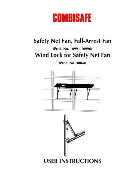
<strong>Safety</strong> <strong>Net</strong> <strong>Fan</strong>, <strong>Fall</strong>-<strong>Arrest</strong> <strong>Fan</strong><br />
(Prod. No. 10991-10996)<br />
Wind Lock for <strong>Safety</strong> <strong>Net</strong> <strong>Fan</strong><br />
(Prod. No.10864)<br />
USER INSTRUCTIONS<br />
10864_000
<strong>Safety</strong> <strong>Net</strong> <strong>Fan</strong>, <strong>Fall</strong>-<strong>Arrest</strong> <strong>Fan</strong> (Prod. No. 10991-10996) Wind Lock for <strong>Safety</strong> <strong>Net</strong><br />
Contents<br />
This manual contains information on <strong>Fall</strong>-<strong>Arrest</strong> <strong>Fan</strong> and Wind Lock.<br />
The Wind Lock complements the <strong>Fall</strong>-<strong>Arrest</strong> <strong>Fan</strong> and is used in order to stabilize<br />
the fan during windy conditions.<br />
SAFETY NET FAN, FALL-ARREST FAN<br />
GENERAL INFO ..........................................................................................6<br />
TECHNICAL DATA .....................................................................................7<br />
Dimensions and weights ........................................................................7<br />
<strong>Fall</strong>-<strong>Arrest</strong> <strong>Fan</strong>, parts ..............................................................................9<br />
Accessories ..........................................................................................12<br />
DESIGN AND FUNCTION ........................................................................24<br />
Overlap ...............................................................................................24<br />
RIGGING ..................................................................................................27<br />
Delivery ..............................................................................................27<br />
Rigging, tools and equipment ..............................................................27<br />
Assembly of Frame and Tube ...............................................................28<br />
Fitting Tubes to the <strong>Safety</strong> <strong>Fan</strong> <strong>Net</strong> .......................................................31<br />
Attaching the <strong>Net</strong> to the Frames and Tubes ..........................................33<br />
Positioning limits according to EN1263-2 ............................................37<br />
INSTALLATION ........................................................................................38<br />
Lifting ..................................................................................................38<br />
Anchorage loads ..................................................................................39<br />
Wind, material and snow loads ...........................................................42<br />
RESCUE FROM THE NET ..........................................................................58<br />
SAFETY INSTRUCTIONS ...........................................................................59<br />
Maintenance .......................................................................................59<br />
Inspection ............................................................................................59<br />
Storage ................................................................................................61<br />
Discarding ...........................................................................................61<br />
Declaration of conformity ....................................................................62<br />
3
Contents <strong>Safety</strong> <strong>Net</strong> <strong>Fan</strong>, <strong>Fall</strong>-<strong>Arrest</strong> <strong>Fan</strong> (Prod. No. 10991-10996) Wind Lock for<br />
WIND LOCK FOR SAFETY NET FAN<br />
GENERAL INFO ........................................................................................64<br />
TECHNICAL DATA ....................................................................................65<br />
Wind lock 10864 .................................................................................65<br />
Dimensions and weights ......................................................................66<br />
DESIGN AND FUNCTION ........................................................................71<br />
Wind loads ..........................................................................................71<br />
FITTING ....................................................................................................72<br />
Delivery ...............................................................................................72<br />
Fitting positions ....................................................................................72<br />
Fitting, tools and equipment .................................................................72<br />
Fitting the wind lock to the <strong>Safety</strong> <strong>Net</strong> <strong>Fan</strong> ...........................................73<br />
SAFETY INSTRUCTIONS ...........................................................................81<br />
Maintenance ........................................................................................81<br />
Inspection ............................................................................................81<br />
Disposal ...............................................................................................81<br />
© <strong>Combisafe</strong> International AB - UI 10991-10996, 10864-EN-1239<br />
Subject to changes.<br />
4
<strong>Safety</strong> <strong>Net</strong> <strong>Fan</strong>, <strong>Fall</strong>-<strong>Arrest</strong> <strong>Fan</strong><br />
Contents<br />
<strong>Safety</strong> <strong>Net</strong> <strong>Fan</strong>, <strong>Fall</strong>-<strong>Arrest</strong> <strong>Fan</strong><br />
(Prod.No. 10991-10996)<br />
5
General info<br />
<strong>Safety</strong> <strong>Net</strong> <strong>Fan</strong>, <strong>Fall</strong>-<strong>Arrest</strong> <strong>Fan</strong><br />
General info<br />
The <strong>Safety</strong> <strong>Net</strong> <strong>Fan</strong> is available in one category: <strong>Fall</strong>-<strong>Arrest</strong>. This type of fan is<br />
approved both for man catching and material catching.<br />
The <strong>Fall</strong>-<strong>Arrest</strong> <strong>Fan</strong> conforms to the requirements set out in “EN 1263-1 <strong>Safety</strong> nets<br />
-Part 1: <strong>Safety</strong> requirements, test methods” (See the declaration of conformity) and<br />
must be installed in accordance with “EN 1263-2 <strong>Safety</strong> nets -Part 2: <strong>Safety</strong><br />
requirements for the positioning limits”, see image 40.<br />
The following example can be used for knowing what kind of protection that is<br />
required. A material catching fan is generally used on high-rise buildings to<br />
protect the workforce and pedestrians on the ground, or the facade of the building<br />
while work is being carried out overhead. The <strong>Fall</strong>-<strong>Arrest</strong> <strong>Fan</strong> is generally used<br />
when work on formwork or steel/prefab erection is carried out close to the edge<br />
and where there is a risk of falling. The <strong>Fall</strong>-<strong>Arrest</strong> <strong>Fan</strong> combines both<br />
applications.<br />
All <strong>Safety</strong> <strong>Net</strong> <strong>Fan</strong>s prod.no 10991-10996 extend 3,3 metres out from the facade<br />
and can be installed using the range of accessories available.<br />
The <strong>Safety</strong> <strong>Net</strong> <strong>Fan</strong> is designed to be folded up against the facade to allow for easy<br />
crane access below, or as a safety precaution in high winds or heavy snowfall.<br />
The design is such that the impact from a fall is partly absorbed by the mesh and<br />
partly by the frame. The <strong>Fall</strong>-<strong>Arrest</strong> <strong>Fan</strong> is designed to catch a person falling from<br />
a height of up to 6 metres, however, the recommendation is to install the <strong>Safety</strong><br />
<strong>Net</strong> <strong>Fan</strong> as close to the working level as possible in order to minimise the risk of<br />
injury in the event of a fall.<br />
The <strong>Fall</strong>-<strong>Arrest</strong> <strong>Fan</strong> has a mesh size of 60 x 60 mm. All <strong>Combisafe</strong> <strong>Safety</strong> <strong>Net</strong> <strong>Fan</strong>s<br />
are equipped with a fine mesh (20 x 20 mm) overlay net as standard to catch small<br />
objects.<br />
In some cases the <strong>Safety</strong> <strong>Net</strong> <strong>Fan</strong>s can be supplemented with scaffold/debris sheets<br />
if denser coverage is required. Wind loads, which are often a problem, must be<br />
taken into consideration.<br />
The <strong>Fall</strong>-<strong>Arrest</strong> <strong>Fan</strong>s are manufactured of steel and aluminium to create the<br />
optimal combination of strength and weight.<br />
Assembly, rigging and repairs should always be carried out by competent<br />
personnel. It is therefore strongly recommended that all involved with the<br />
selection and installation of <strong>Safety</strong> <strong>Net</strong> <strong>Fan</strong>s complete a <strong>Combisafe</strong> product<br />
training course.<br />
6
<strong>Safety</strong> <strong>Net</strong> <strong>Fan</strong>, <strong>Fall</strong>-<strong>Arrest</strong> <strong>Fan</strong><br />
Technical data<br />
Dimensions and weights<br />
Technical data<br />
10991-10996_001<br />
Image 1. Dimensions<br />
Prod. No. A B C Weight<br />
10991 4,2 m 2,5 m 2 ± 0.5 m 68 kg<br />
10992 4,2 m 3,0 m 2 ± 0.5 m 72 kg<br />
10993 4,2 m 3,5 m 2 ± 0.5 m 76 kg<br />
10994 6,0m 2,5 m 4 ± 0.5 m 76 kg<br />
10995 6,0 m 3,0 m 4 ± 0.5 m 80 kg<br />
10996 6,0 m 3,5 m 4 ± 0.5 m 84 kg<br />
7
Technical data<br />
<strong>Safety</strong> <strong>Net</strong> <strong>Fan</strong>, <strong>Fall</strong>-<strong>Arrest</strong> <strong>Fan</strong><br />
10991-10996_002<br />
Image 2. Dimensions<br />
8
<strong>Safety</strong> <strong>Net</strong> <strong>Fan</strong>, <strong>Fall</strong>-<strong>Arrest</strong> <strong>Fan</strong><br />
Technical data<br />
<strong>Fall</strong>-<strong>Arrest</strong> <strong>Fan</strong>, parts<br />
11 10<br />
1<br />
2<br />
8<br />
9<br />
12<br />
4<br />
7<br />
3 6<br />
10991-10996_003 B<br />
4<br />
5<br />
Image 3. Parts<br />
Pos. Quantity Art. no. Description Weight<br />
Standard parts for all <strong>Safety</strong> <strong>Net</strong> <strong>Fan</strong>s<br />
1 1 * <strong>Safety</strong> <strong>Net</strong> <strong>Fan</strong>, <strong>Net</strong> *<br />
2 2 10432 Square-Round Coupler 1.60 kg<br />
3 2 * <strong>Safety</strong> <strong>Net</strong> <strong>Fan</strong> Frame *<br />
4 4 100025 Lock Nut M12 0.01 kg<br />
5 2 100200 Bolt M12x90 0.10 kg<br />
6 2 10766 Diagonal Tube 4.2 m 7.2 kg<br />
7 2 100338 Bolt M6x16 0.02 kg<br />
8 2 100061 Lock Nut M6 0.01 kg<br />
9 2 200361 Double Coupler 1.40 kg<br />
10 2 * Horizontal Tube *<br />
11 4 100029 Spring Hook 0.03 kg<br />
12 2 100153 Bolt M12x80 0.10 kg<br />
* Parts that can vary- See table on the next page<br />
9
Technical data<br />
<strong>Safety</strong> <strong>Net</strong> <strong>Fan</strong>, <strong>Fall</strong>-<strong>Arrest</strong> <strong>Fan</strong><br />
Pos. Quantity Art. no. Description Weight<br />
10991/10992/10993 <strong>Safety</strong> <strong>Net</strong> <strong>Fan</strong> <strong>Fall</strong>-<strong>Arrest</strong> 4.2 m<br />
1 1 10793 <strong>Safety</strong> <strong>Net</strong> <strong>Fan</strong> <strong>Net</strong> 5.2x3.3 m* 8,7 kg<br />
3 2<br />
10763<br />
10762<br />
10973<br />
Frame<br />
2.5m<br />
3.0m<br />
3.5m<br />
11.7 kg<br />
13.8 kg<br />
15.9 kg<br />
10 2 10769 Aluminium Tube 4.2 m (with holes) 7.1 kg<br />
10994/10995/10996 <strong>Safety</strong> <strong>Net</strong> <strong>Fan</strong> <strong>Fall</strong>-<strong>Arrest</strong> 6 m<br />
1 1 10796 <strong>Safety</strong> <strong>Net</strong> <strong>Fan</strong> <strong>Net</strong> 7.0x3.3 m* 11.2 kg<br />
3 2<br />
10763<br />
10762<br />
10973<br />
Frame<br />
2.5m<br />
3.0<br />
3.5m<br />
11.7 kg<br />
13.8 kg<br />
15.9 kg<br />
10 2 10771 Aluminium Tube 6 m (with holes) 10.2 kg<br />
*Supplemented with 20 x 20 mm fine mesh overlay net.<br />
Storage and transport design of Frame and Tube<br />
10991-10996_004<br />
Image 4. Assembly level at delivery<br />
The entire metal Frame is delivered as one unit with Art.No. 10773/10775/10987<br />
(2.5/3.0/3.5m Frame).<br />
10
<strong>Safety</strong> <strong>Net</strong> <strong>Fan</strong>, <strong>Fall</strong>-<strong>Arrest</strong> <strong>Fan</strong><br />
Technical data<br />
Storage and transport assembly level of <strong>Net</strong> unit<br />
10991-10996_005<br />
Image 5. Assembly level of <strong>Net</strong> unit<br />
The <strong>Net</strong> is delivered as an assembly including complete <strong>Net</strong> with aluminium<br />
Tubes inserted. Art.No. 10790/10791 (4.2/6.0m <strong>Fan</strong>).<br />
11
Technical data<br />
<strong>Safety</strong> <strong>Net</strong> <strong>Fan</strong>, <strong>Fall</strong>-<strong>Arrest</strong> <strong>Fan</strong><br />
Accessories<br />
10044 Slab Attachment<br />
10991-10996_006<br />
Image 6. Slab Attachment<br />
Pos. Quantity Art. no. Designation Weight<br />
1 1 10044 Slab Attachment 5,1 kg<br />
2 1 100025 Lock Nut M12 0,01 kg<br />
3 1 100153 Bolt M12x80 0,09 kg<br />
The Slab Attachment is used to install the <strong>Safety</strong> <strong>Net</strong> <strong>Fan</strong> on to a flat surface. The<br />
most common use is when installing the <strong>Net</strong> on the edge of a slab, often together<br />
with a Knee Brace (Art. No. 10878). The Slab Attachment can be used separately<br />
if the <strong>Net</strong> is supported against the building facade, or together with the Extension<br />
(Art. No. 10882) which provides reaction support from the structure below.<br />
NOTE<br />
When using the Slab Attachment it is recommended to use Adjustable<br />
Couplers Art.No. 10933 shown in image 7 instead of Square-Round<br />
Couplers shown in image 3 due to greater flexibility regarding assembly<br />
positions.<br />
12
<strong>Safety</strong> <strong>Net</strong> <strong>Fan</strong>, <strong>Fall</strong>-<strong>Arrest</strong> <strong>Fan</strong><br />
Technical data<br />
10933 Adjustable Coupler<br />
Image 7. Adjustable Coupler<br />
The Adjustable Coupler is used in combination with the Slab Attachment. In the<br />
normal case the Adjustable Coupler is not fixed to the Slab Attachment but<br />
allowed to slide freely. This gives possibility to always get the <strong>Net</strong> in the correct<br />
height compared to the slab edge, independent of how the Slab Attachment is<br />
adjusted. The Adjustable Coupler is allowed to rest at the edge of the slab<br />
according to image 9 and this also effectively eliminates all openings between<br />
slab and <strong>Safety</strong> <strong>Net</strong> <strong>Fan</strong>. However if needed for special cases, it is possible to fix<br />
the position of the Adjustable Coupler on the Slab Attachment with a bolt and nut.<br />
10991-10996_008<br />
10991-10996_007<br />
Image 8. Normal assembly position of Adjustable Coupler on straight slab<br />
13
Technical data<br />
<strong>Safety</strong> <strong>Net</strong> <strong>Fan</strong>, <strong>Fall</strong>-<strong>Arrest</strong> <strong>Fan</strong><br />
10882 Extension<br />
10991-10996_009<br />
Image 9. Extension<br />
Pos. Quantity Art. no. Designation Weight<br />
1 1 10435 Extension 5.2 kg<br />
2 1 100025 Lock Nut M12 0.01 kg<br />
3 1 100153 Bolt M12x80 0.09 kg<br />
The Extension extends the lower support of the <strong>Safety</strong> <strong>Net</strong> <strong>Fan</strong> downwards and<br />
can be used together with most attachments. The support plate holes permit<br />
anchorage if necessary. The Extensions are frequently used to reach down to the<br />
floor below and support against the edge of the slab. When the <strong>Safety</strong> <strong>Net</strong> <strong>Fan</strong> is<br />
installed using the Facade Attachment, the Extension can be used to avoid the<br />
lower corner of the <strong>Safety</strong> <strong>Net</strong> <strong>Fan</strong> being pressed against the facade, the Frame of<br />
the <strong>Safety</strong> <strong>Net</strong> <strong>Fan</strong> then remains in the vertical plane. The Extension can also be<br />
used together with the Knee Brace in case of downstand slab, described in the<br />
Knee Brace section.<br />
The adjustment range of the Extension is 1m. In the following examples in image<br />
11 and 12 the possible usage between different slab distances/fixing points can be<br />
found for different lengths of the Frame and for adjustable/fixed attachments.<br />
14
<strong>Safety</strong> <strong>Net</strong> <strong>Fan</strong>, <strong>Fall</strong>-<strong>Arrest</strong> <strong>Fan</strong><br />
Technical data<br />
10991-10996_010<br />
Image 10. Adjustment range with adjustable upper attachment<br />
Distance [mm]<br />
2,5m body<br />
(10991,10994)<br />
3,0m body<br />
(10992,10995)<br />
MIN 2460 2960 3460<br />
MAX 3960 4460 4960<br />
3,5m body<br />
(10993,10996)<br />
15
Technical data<br />
<strong>Safety</strong> <strong>Net</strong> <strong>Fan</strong>, <strong>Fall</strong>-<strong>Arrest</strong> <strong>Fan</strong><br />
10991-10996_011<br />
Image 11. Adjustment range with fixed upper attachment<br />
Distance [mm]<br />
2,5m body<br />
(10991,10994)<br />
3,0m body<br />
(10992,10995)<br />
MIN 2475 2975 3475<br />
MAX 3475 3975 4475<br />
3,5m body<br />
(10993,10996)<br />
16
<strong>Safety</strong> <strong>Net</strong> <strong>Fan</strong>, <strong>Fall</strong>-<strong>Arrest</strong> <strong>Fan</strong><br />
Technical data<br />
10878 Knee Brace<br />
10991-10996_012<br />
Image 12. Knee Brace<br />
Pos. Quantity Art. no. Designation Weight<br />
1 1 10878 Knee Brace 8.9 kg<br />
The Knee Brace is used to support the <strong>Safety</strong> <strong>Net</strong> <strong>Fan</strong> below a slab. The Knee Brace<br />
is usually used together with the Slab Attachment when the <strong>Safety</strong> <strong>Net</strong> <strong>Fan</strong> is<br />
installed around an open slab edge. In case of downstand slabs it is possible to use<br />
the Knee Brace in combination with an Extension according to image 13.<br />
17
Technical data<br />
<strong>Safety</strong> <strong>Net</strong> <strong>Fan</strong>, <strong>Fall</strong>-<strong>Arrest</strong> <strong>Fan</strong><br />
10991-10996_013<br />
Image 13. Knee Brace in combination with Extension<br />
18
<strong>Safety</strong> <strong>Net</strong> <strong>Fan</strong>, <strong>Fall</strong>-<strong>Arrest</strong> <strong>Fan</strong><br />
Technical data<br />
10439 Facade Attachment<br />
Image 14. Facade Attachment<br />
Pos. Quantity Art. no. Designation Weight<br />
1 1 10439 Facade Attachment 4.2 kg<br />
2 2 100162 Bolt M12x120 0.1 kg<br />
The Facade Attachment is fitted to the facade using a fixing/anchor//form tie. The<br />
<strong>Safety</strong> <strong>Net</strong> <strong>Fan</strong> is installed directly on the facade using two Facade Attachments.<br />
The <strong>Safety</strong> <strong>Net</strong> <strong>Fan</strong> can be equipped with padding to protect the facade. The<br />
Extension can also be used to extend the lower support to an appropriate position.<br />
19
Technical data<br />
<strong>Safety</strong> <strong>Net</strong> <strong>Fan</strong>, <strong>Fall</strong>-<strong>Arrest</strong> <strong>Fan</strong><br />
10440 Scaffold Attachment<br />
Image 15. Scaffold Attachment<br />
Pos. Quantity Art. no. Designation Weight<br />
1 1 10440 Scaffold Attachment 4.0 kg<br />
2 2 100162 Bolt M12x120 0.1 kg<br />
The Scaffold Attachment is equipped with two couplers for connection on vertical<br />
scaffold Tubes. The <strong>Safety</strong> <strong>Net</strong> <strong>Fan</strong> is usually supported by vertical scaffold<br />
standards, but in some cases a vertical Tube is fitted to the <strong>Safety</strong> <strong>Net</strong> <strong>Fan</strong>. In all<br />
cases the scaffold to which the fan is attached, must be assessed by a competent<br />
person as capable of accepting the loads imposed by the fan.<br />
20
50<br />
210<br />
<strong>Safety</strong> <strong>Net</strong> <strong>Fan</strong>, <strong>Fall</strong>-<strong>Arrest</strong> <strong>Fan</strong><br />
Technical data<br />
10964 Loose Slab Attachment<br />
405<br />
255<br />
1<br />
19<br />
45<br />
18<br />
2<br />
10991-10996_016 B<br />
Image 16. Loose Slab Attachment<br />
Pos. Quantity Art. no. Description Weight<br />
1 1 10964 Loose Slab Attachment 3.0 kg<br />
2 2 100159 Bolt M12x110 0.1 kg<br />
The Loose Slab Attachment is placed around a slab edge and is particularly useful<br />
if space is limited on top of the slab edge. It is even possible to use the Loose Slab<br />
Attachment through a brick wall or similar. Due to its sleek design only 10mm of<br />
vertical clearance is necessary. It is important that the Loose Slab Attachment get<br />
support from the vertical part of the slab, according to image 17.<br />
10991-10996_017<br />
Image 17. Assembly of Loose Slab Attachment<br />
21
Technical data<br />
<strong>Safety</strong> <strong>Net</strong> <strong>Fan</strong>, <strong>Fall</strong>-<strong>Arrest</strong> <strong>Fan</strong><br />
10965/10966 Offset Beam 750/900mm<br />
Image 18. Offset Beam<br />
10997-10999_019 B<br />
Pos. Quantity Art. no. Description Weight<br />
1 1 10965<br />
10966<br />
Offset Beam 750mm<br />
Offset Beam 900mm<br />
12.4 kg<br />
14.6 kg<br />
The Offset Beam is used for cases when the <strong>Safety</strong> <strong>Net</strong> <strong>Fan</strong> needs to be moved<br />
outwards from the slab edge. The Offset Beams are available in two different<br />
lengths, 750 and 900mm. It can be combined with several attachments and ways<br />
of assembling the fan, some examples follow in image 19. Always use two<br />
anchors to fixate the Offset Beam to the structure. Make sure that the anchor has<br />
enough distance to the slab edge.<br />
!<br />
2x<br />
10991-10996_019 B<br />
Image 19. Examples of assembly-Offset Beam<br />
22
<strong>Safety</strong> <strong>Net</strong> <strong>Fan</strong>, <strong>Fall</strong>-<strong>Arrest</strong> <strong>Fan</strong><br />
Technical data<br />
10047 Lifting Sling<br />
3105-3116_062<br />
Image 20. Lifting Sling<br />
The Lifting Sling is used to lift an assembled <strong>Safety</strong> <strong>Net</strong> <strong>Fan</strong> in to position.<br />
23
Design and function<br />
<strong>Safety</strong> <strong>Net</strong> <strong>Fan</strong>, <strong>Fall</strong>-<strong>Arrest</strong> <strong>Fan</strong><br />
Design and function<br />
The <strong>Safety</strong> <strong>Net</strong> <strong>Fan</strong> is assembled on the ground and lifted into position using a<br />
crane. Assembly is performed using different accessories to adapt the <strong>Safety</strong> <strong>Net</strong><br />
<strong>Fan</strong> to the building.<br />
The use of accessories is described under “Installation”.<br />
The lift method is described under “Lifting”.<br />
Once the <strong>Safety</strong> <strong>Net</strong> <strong>Fan</strong>s have been lifted into position, they can be connected<br />
together. The most common is the overlap method.<br />
When the <strong>Safety</strong> <strong>Net</strong> <strong>Fan</strong>s have been installed they can be folded up to allow the<br />
crane to access to the area below. The <strong>Safety</strong> <strong>Net</strong> <strong>Fan</strong>s can also be folded up for<br />
protection against high winds or heavy snow.<br />
There are also solutions for <strong>Safety</strong> <strong>Net</strong> <strong>Fan</strong>s to fit around corners.<br />
Overlap<br />
To ensure that there is no gap between the <strong>Safety</strong> <strong>Net</strong> <strong>Fan</strong>s, the fans must either<br />
be laced together or overlapped. Different procedures are used for Protection<br />
<strong>Safety</strong> <strong>Net</strong> <strong>Fan</strong>s and <strong>Fall</strong>-<strong>Arrest</strong> <strong>Safety</strong> <strong>Net</strong> <strong>Fan</strong>s.<br />
The most common method is alternate upper and lower fans, and to first position<br />
two lower fans followed by fitting an upper fan between them which overlaps<br />
both of the lower fans. This method permits easy folding up and in doing so makes<br />
the area below accessible for a crane. Careful planning is needed to ensure that<br />
the upper <strong>Safety</strong> <strong>Net</strong> <strong>Fan</strong>s are positioned where material will be loaded.<br />
The overlap is created in different ways depending on whether the <strong>Safety</strong> <strong>Net</strong> <strong>Fan</strong>s<br />
are installed using Slab Attachments or Facade/Scaffold Attachments. When the<br />
Slab Attachment is used the height difference for the overlap is created by<br />
adjusting the Square-Round Coupler to different levels. When the Facade<br />
Attachment or Scaffold Attachment is used the height difference is created using<br />
the different support levels within the bracket.<br />
3105-3116_016<br />
Image 21. Common overlap<br />
An alternative overlap method is to create an upper and a lower side on the <strong>Safety</strong><br />
<strong>Net</strong> <strong>Fan</strong>. This is done by setting both couplers at different heights when using the<br />
Slab Attachment. When using the Facade and Scaffold Bracket, an upper and a<br />
lower position for each safety <strong>Net</strong> is used. This method is quicker when rigging,<br />
but it limits flexibility to fold individual fans up for effective crane access.<br />
24
<strong>Safety</strong> <strong>Net</strong> <strong>Fan</strong>, <strong>Fall</strong>-<strong>Arrest</strong> <strong>Fan</strong><br />
Design and function<br />
3105-3116_017<br />
Image 22. Alternative overlap<br />
Effective length<br />
The effective length of the fan depends on the extent of the overlap.<br />
- For a 6 metre fan with an overlap of 1 metre the effective length is 5 metres<br />
other than for the first fan.<br />
- For a 4 metre fan with an overlap of 1 metre the effective length is 3 metres<br />
other than for the first fan.<br />
6 m<br />
5 m<br />
5 m<br />
5 m<br />
5 m<br />
3105-3116_018<br />
Image 23. Effective length<br />
Length of the overlap<br />
The required length of the overlap differs between Protection and <strong>Fall</strong>-<strong>Arrest</strong><br />
<strong>Safety</strong> <strong>Net</strong> <strong>Fan</strong>s.<br />
The overlap for a Protection <strong>Safety</strong> <strong>Net</strong> <strong>Fan</strong> only needs to prevent material from<br />
falling between the fans, and the extent of overlap may depend on the<br />
requirements appropriate for the site in question.<br />
3105-3116_019<br />
Image 24. Protection <strong>Safety</strong> <strong>Net</strong> <strong>Fan</strong> overlap<br />
The overlap for a <strong>Fall</strong>-<strong>Arrest</strong> <strong>Safety</strong> <strong>Net</strong> <strong>Fan</strong> must be at least 0.75 metres. Note that<br />
<strong>Safety</strong> <strong>Net</strong> <strong>Fan</strong>s "waist in" and are frequently smaller in the middle. The overlap<br />
here must be 0.75 metres. If a 1 metre overlap is made at the outer edges generally<br />
the minimum overlap of 0.75 metres is maintained.<br />
25
Design and function<br />
<strong>Safety</strong> <strong>Net</strong> <strong>Fan</strong>, <strong>Fall</strong>-<strong>Arrest</strong> <strong>Fan</strong><br />
1 m<br />
3105-3116_020<br />
> 0,75 m<br />
Image 25. <strong>Fall</strong>-<strong>Arrest</strong> <strong>Safety</strong> <strong>Net</strong> <strong>Fan</strong> overlap<br />
The <strong>Safety</strong> <strong>Net</strong> <strong>Fan</strong>s can also be joined by lacing them together. This is done using<br />
a Coupling Rope to EN1263-1. The rope is used to lace every other mesh in the<br />
<strong>Net</strong>s together, after which the ends are secured. Ensure that there are no openings<br />
larger than 100 mm (as required in EN1263-2). Only Protection <strong>Safety</strong> <strong>Net</strong> <strong>Fan</strong>s<br />
can be laced.<br />
3105-3116_021<br />
Image 26. Joining <strong>Net</strong>s by lacing<br />
26
<strong>Safety</strong> <strong>Net</strong> <strong>Fan</strong>, <strong>Fall</strong>-<strong>Arrest</strong> <strong>Fan</strong><br />
Rigging<br />
Rigging<br />
Delivery<br />
The <strong>Safety</strong> <strong>Net</strong> <strong>Fan</strong> is delivered in pieces and must be assembled before use. The<br />
<strong>Safety</strong> <strong>Net</strong> <strong>Fan</strong> may be partly assembled before delivery.<br />
Rigging, tools and equipment<br />
The following tools are required to assemble the <strong>Safety</strong> <strong>Net</strong> <strong>Fan</strong>:<br />
• Spanners, or preferably ratchet handle and sockets.<br />
• Gloves.<br />
• Pen to mark Tubes.<br />
• Measuring tape.<br />
• Knife.<br />
• Assembly Aid, Art.No. 10671, (weight 2.5 kg).<br />
Place two Assembly Aids at the intended c/c spacing from the Frames. Position the<br />
Frames within the Assembly Aids as shown.<br />
Position the Frames at the correct spacing to simplify fan assembly.<br />
If the <strong>Safety</strong> <strong>Net</strong> <strong>Fan</strong> Frames are delivered assembled, place two Assembly Aids at<br />
the intended c/c spacing from the Frames. Position the Frames within the<br />
Assembly Aids as shown.<br />
10991-10996_027<br />
Image 27. Positioning the Frames on the Assembly Aid<br />
27
Rigging<br />
<strong>Safety</strong> <strong>Net</strong> <strong>Fan</strong>, <strong>Fall</strong>-<strong>Arrest</strong> <strong>Fan</strong><br />
Assembly of Frame and Tube<br />
If the <strong>Safety</strong> <strong>Net</strong> <strong>Fan</strong> is not delivered partly assembled, follow assembly sequence<br />
below.<br />
1. Assemble the Frame and Tube using M12 x 90 bolts and lock nuts. Do not<br />
tighten completely. Screw on the nuts so that they permit the Tube to move<br />
without clamping.The parts can be placed on the Assembly Aid for easier<br />
assembly.<br />
Image 28. Assembly of Frame and diagonal Tube<br />
10991-10996_028<br />
2. Assemble the Double Couplers on the round Tube. Tighten the couplers to<br />
secure it. These couplers may need to be adjusted later.<br />
Assemble the Square-Round Coupler on the square body. Tighten the<br />
coupler.<br />
NOTE<br />
Ensure that the couplers are assembled in the correct direction (see image<br />
29).<br />
NOTE<br />
The position of the Double Coupler determines the angle of the fan.<br />
Approximately 100 mm from the end of the Tube to the middle of the<br />
coupler is usually about right (see image 29). The <strong>Safety</strong> <strong>Net</strong> <strong>Fan</strong>s include a<br />
measurement decal which facilitates positioning.<br />
NOTE<br />
When the <strong>Safety</strong> <strong>Net</strong> <strong>Fan</strong> is assembled with the Slab Attachment and Knee<br />
Brace, the position of the coupler is determined by the overlap. See the<br />
section “Overlap” Place the couplers at the required distance from the end<br />
of the Frame. Position for the upper fan: approximately 130 mm. Position<br />
for the lower fan: approximately 200 mm.<br />
28
<strong>Safety</strong> <strong>Net</strong> <strong>Fan</strong>, <strong>Fall</strong>-<strong>Arrest</strong> <strong>Fan</strong><br />
Rigging<br />
10991-10996_029<br />
Image 29. Positioning of couplers<br />
3. Make sure the M6 screw and nut are mounted in the end of the round tube<br />
(See Item 7 and 8 under “<strong>Fall</strong>-<strong>Arrest</strong> <strong>Fan</strong>, parts”). This secures the coupler<br />
from sliding off the Tube when lifting the <strong>Safety</strong> <strong>Net</strong> <strong>Fan</strong> in case of forgetting<br />
tightening the coupler.<br />
10991-10996_030<br />
Image 30. The securing screw/nut<br />
29
Rigging<br />
<strong>Safety</strong> <strong>Net</strong> <strong>Fan</strong>, <strong>Fall</strong>-<strong>Arrest</strong> <strong>Fan</strong><br />
4. Make sure that the Frames are positioned at the correct spacing to simplify<br />
fan assembly. If preferred it is possible to put a Scaffold Tube horizontally<br />
under the Assembly Aids to get them levelled according to image 31.<br />
NOTE<br />
The spacing of the Frames depends on the size of fan, type of fan, and the<br />
planned location on the specific building. See “Technical data”.<br />
10991-10996_031<br />
Image 31. Place the Frames with correct c-c spacing<br />
30
<strong>Safety</strong> <strong>Net</strong> <strong>Fan</strong>, <strong>Fall</strong>-<strong>Arrest</strong> <strong>Fan</strong><br />
Rigging<br />
Fitting Tubes to the <strong>Safety</strong> <strong>Fan</strong> <strong>Net</strong><br />
Before the Tubes are threaded into the <strong>Net</strong>, it is helpful to mark the planned<br />
position of the couplers on the Tubes, i.e. the distance between the Frames,<br />
should be marked out. The distance between the Frames can be found in image 1.<br />
1. Insert Tubes through the two hemmed edges in the <strong>Net</strong>. This is easier if the<br />
20mm mesh <strong>Net</strong> is positioned at the bottom.<br />
Image 32. Inserting the outer Tubes into the <strong>Safety</strong> <strong>Fan</strong> <strong>Net</strong><br />
2. Secure the corner of the <strong>Net</strong> through the hole in the end on the Tube with<br />
the metal snaphooks. Ensure that the border rope is enclosed inside the snap<br />
hooks.<br />
10991-10996_033 B<br />
10991-10996_032 B<br />
Image 33. Secure the <strong>Net</strong> with snap hooks<br />
31
Rigging<br />
<strong>Safety</strong> <strong>Net</strong> <strong>Fan</strong>, <strong>Fall</strong>-<strong>Arrest</strong> <strong>Fan</strong><br />
3. Make sure that the net is secured to all four tube edges according to the<br />
circles in image 34.<br />
Image 34. Secure the ends of both Tubes<br />
32
<strong>Safety</strong> <strong>Net</strong> <strong>Fan</strong>, <strong>Fall</strong>-<strong>Arrest</strong> <strong>Fan</strong><br />
Rigging<br />
Attaching the <strong>Net</strong> to the Frames and Tubes<br />
Image 35. Secure <strong>Net</strong> to Frames and raking Tubes<br />
NOTE<br />
It is important that the <strong>Net</strong> is positioned correctly. The finer 20x20mm<br />
mesh <strong>Net</strong> must always be on top. There are blue and yellow marking tags<br />
on the net edges, showing the position of the couplers. The blue tags should<br />
be placed on the Frame side and the yellow at the round Tube.<br />
1. Place the <strong>Net</strong> with the aluminium Tubes on top of the Frames.<br />
2. Fit the inner Tube in the couplers on the Frame and ensure that the Frames<br />
pass through the <strong>Net</strong> outside the Tube.<br />
The edge of the <strong>Net</strong> has colour markings, the blue side must be against the<br />
Frame-and the Square-Round Coupler, and the yellow side must be out<br />
towards the round Tube. Insert the square frame through the cutout in the<br />
net. Place the horizontal Tube in the coupler and ensure that no more than<br />
one mesh cord <strong>Net</strong> yarn gets caught in the coupler.<br />
33
Rigging<br />
<strong>Safety</strong> <strong>Net</strong> <strong>Fan</strong>, <strong>Fall</strong>-<strong>Arrest</strong> <strong>Fan</strong><br />
<br />
Image 36. Tube mounted in Frame coupler<br />
NOTE<br />
If the <strong>Safety</strong> <strong>Net</strong> <strong>Fan</strong> is not used together with the Slab Attachment 10044,<br />
make sure the M12 bolt and locking nut (See Item 4 and 12 under “<strong>Fall</strong>-<br />
<strong>Arrest</strong> <strong>Fan</strong>, parts”) are mounted through the Frame. This secures the<br />
Square-Round Coupler from sliding off the Frame in case it has not been<br />
properly tightened.<br />
10991-10996_037 B<br />
10991-10996_036 B<br />
Image 37. The securing bolt/nut<br />
34
<strong>Safety</strong> <strong>Net</strong> <strong>Fan</strong>, <strong>Fall</strong>-<strong>Arrest</strong> <strong>Fan</strong><br />
Rigging<br />
3. Make sure that the <strong>Net</strong> goes around the Frame. This is important when the<br />
Slab Attachment is used so that it can be threaded through the <strong>Net</strong> and into<br />
the Frame. Tighten the couplers.<br />
4. Place the outer aluminium Tube in the couplers on the raking Tubes. Make<br />
sure that no mesh cords are caught in the coupler. If it is difficult to close the<br />
coupler due to the <strong>Net</strong> being in the way, it is allowed to cut one mesh but<br />
no more. Adjust lower couplers until the net is taut. Remember to tighten the<br />
coupler.<br />
10991-10996_038 B<br />
Image 38. Assemble the outer Tube on the raking Tube<br />
5. Tie the Pull Rope, Art. No. 10861 between the inner and middle horizontal<br />
Tubes in the centre of the <strong>Safety</strong> <strong>Net</strong> <strong>Fan</strong>. This rope will be used to fold up<br />
the <strong>Safety</strong> <strong>Net</strong> <strong>Fan</strong>.<br />
NOTE<br />
If Wind Locks are used, Pull Ropes are provided in that kit. See further<br />
down in this user instruction for details about <strong>Combisafe</strong> Wind Lock.<br />
35
Rigging<br />
<strong>Safety</strong> <strong>Net</strong> <strong>Fan</strong>, <strong>Fall</strong>-<strong>Arrest</strong> <strong>Fan</strong><br />
6. The <strong>Safety</strong> <strong>Net</strong> <strong>Fan</strong> is now assembled and ready for use. After fitting<br />
attachments the <strong>Safety</strong> <strong>Net</strong> <strong>Fan</strong> can be lifted into place. See section<br />
"Installation".<br />
10991-10996_039 B<br />
Image 39. Assembled <strong>Safety</strong> <strong>Net</strong> <strong>Fan</strong><br />
36
<strong>Safety</strong> <strong>Net</strong> <strong>Fan</strong>, <strong>Fall</strong>-<strong>Arrest</strong> <strong>Fan</strong><br />
Rigging<br />
Positioning limits according to EN1263-2<br />
Positioning limits are set out in EN1263-2 and only apply to the <strong>Fall</strong>-<strong>Arrest</strong> <strong>Safety</strong><br />
<strong>Net</strong> <strong>Fan</strong>.<br />
According to “EN1263-2 <strong>Safety</strong> nets: Part 2: <strong>Safety</strong> requirements for the<br />
positioning limits”, a <strong>Fall</strong>-<strong>Arrest</strong> <strong>Fan</strong> designed to catch persons must be positioned<br />
in accordance with the following:<br />
• For a working surface sloping less than 20° the maximum fall height is 6<br />
metres.<br />
• For a working surface sloping more than 20° the maximum fall height is 3<br />
metres.<br />
• The minimum free height below the <strong>Safety</strong> <strong>Net</strong> <strong>Fan</strong> (f) must be at least the<br />
height of the <strong>Safety</strong> <strong>Net</strong> <strong>Fan</strong>. Nothing must obstruct the area below the net,<br />
within the length of the frames.<br />
Installation<br />
<strong>Safety</strong> <strong>Net</strong> <strong>Fan</strong>, <strong>Fall</strong>-<strong>Arrest</strong> <strong>Fan</strong><br />
Installation<br />
Lifting<br />
The <strong>Safety</strong> <strong>Net</strong> <strong>Fan</strong> can be lifted in a number of different ways, however the best<br />
and most common solution is to lift using two slings on the outer Tube, just<br />
outside the Double Couplers.<br />
Make sure that all the couplers are tightened before lifting. Attach a two legged<br />
lifting device that cannot slide.<br />
Be aware of any wind when lifting the <strong>Safety</strong> <strong>Net</strong> <strong>Fan</strong> (the <strong>Safety</strong> <strong>Net</strong> <strong>Fan</strong> catches<br />
a lot of wind). Exercise care when lifting the <strong>Safety</strong> <strong>Net</strong> <strong>Fan</strong> off the ground. There<br />
is a risk of the fan opening and swinging sideways.<br />
10991-10996_041<br />
Image 41. Lifting<br />
38
<strong>Safety</strong> <strong>Net</strong> <strong>Fan</strong>, <strong>Fall</strong>-<strong>Arrest</strong> <strong>Fan</strong><br />
Installation<br />
Anchorage loads<br />
Attachments must always be anchored to the building, i.e. it is not enough to hang<br />
the <strong>Safety</strong> <strong>Net</strong> <strong>Fan</strong> around a slab or on an attachment without fastening it.<br />
These loads apply to the man catching <strong>Safety</strong> <strong>Net</strong> <strong>Fan</strong>.<br />
• The maximum pull-out load on the anchor when the <strong>Safety</strong> <strong>Net</strong> <strong>Fan</strong> is secured<br />
to a facade, independent of attachment, is 16 kN.<br />
• The maximum shear load on the anchor when the <strong>Safety</strong> <strong>Net</strong> <strong>Fan</strong> is secured<br />
on a slab, independent of attachment, is 10 kN.<br />
• These loads are dynamic impact loads.<br />
• Loads can usually be lowered if fan is used only for material catching, contact<br />
<strong>Combisafe</strong> Engineering Service for advice in each individual case.<br />
10<br />
16<br />
10<br />
10<br />
10<br />
Image 42. Reaction forces, general, for wall/slab mounting<br />
39
Installation<br />
<strong>Safety</strong> <strong>Net</strong> <strong>Fan</strong>, <strong>Fall</strong>-<strong>Arrest</strong> <strong>Fan</strong><br />
In addition to the general load cases in image 42, there are further more<br />
attachments that do not comply to the general description. These are showed in<br />
image 43-45.<br />
Image 43. Moment transferred to beam using Steel Jaw Clamp<br />
Image 44. Moment transferred to upstand using Multi Clamp<br />
40
<strong>Safety</strong> <strong>Net</strong> <strong>Fan</strong>, <strong>Fall</strong>-<strong>Arrest</strong> <strong>Fan</strong><br />
Installation<br />
The pull-out load of the inner fastener on Offset Beam Art.No. 10965 and 10966<br />
depending on attachment method is showed in image 45.<br />
8kN (10965)<br />
12kN (10966)<br />
12kN (10965)<br />
16kN (10966)<br />
6kN (10965)<br />
10kN (10966)<br />
10kN 10kN 10kN<br />
Image 45. Reaction forces, Offset Beams<br />
41
Installation<br />
<strong>Safety</strong> <strong>Net</strong> <strong>Fan</strong>, <strong>Fall</strong>-<strong>Arrest</strong> <strong>Fan</strong><br />
Wind, material and snow loads<br />
Wind loads<br />
The <strong>Safety</strong> <strong>Net</strong> <strong>Fan</strong> is a large product and therefore create large wind drag which<br />
is very much depending on the wind direction and the net configuration, for<br />
example if a scaffold sheet is added. Note that the pressure caused by the wind is<br />
exponentially increased with increasing wind speeds.<br />
Please start to pay attention to the behaviour of the fan at high wind speeds<br />
exceeding 15m/s and be prepared to either fold the fan in or tie it down with a<br />
rope to the building (see image 46) if the wind loads become a problem. To<br />
prevent the wind from folding the fan a Wind Lock (Art.No.10864) can be used.<br />
However, for very high wind speeds above actions apply also if Wind Locks are<br />
used. That is done to prevent damage to the fan and the building.<br />
Contact <strong>Combisafe</strong> Engineering Service if any uncertainties.<br />
10991-10996_043<br />
Image 46. <strong>Safety</strong> <strong>Net</strong> <strong>Fan</strong> tied to building with a rope<br />
42
<strong>Safety</strong> <strong>Net</strong> <strong>Fan</strong>, <strong>Fall</strong>-<strong>Arrest</strong> <strong>Fan</strong><br />
Installation<br />
Material and snow loads<br />
The <strong>Safety</strong> <strong>Net</strong> <strong>Fan</strong> is not designed for high loads other than those within<br />
EN1263-1. Keep the fans clear of materials, debris and snow.<br />
Assembling the Slab Attachment and Knee Brace<br />
1. Assemble the Knee Brace on the Frame by opening its two couplers and<br />
place it somewhere along the Frame. Do not tighten the couplers yet.<br />
10991-10996_044<br />
Image 47. Assemble the Knee Brace<br />
2. Assemble the Slab Attachment on the Frames using an M12x80 bolt and nut.<br />
Adjust the Knee Brace and/or Slab Attachment according to the thickness of<br />
the slab.<br />
10991-10996_045<br />
Image 48. Assemble the Slab Attachment<br />
43
Installation<br />
<strong>Safety</strong> <strong>Net</strong> <strong>Fan</strong>, <strong>Fall</strong>-<strong>Arrest</strong> <strong>Fan</strong><br />
3. The <strong>Safety</strong> <strong>Net</strong> <strong>Fan</strong>s are now ready to be lifted into position. See the section<br />
“Overlap” and “Lifting”.<br />
Image 49. <strong>Safety</strong> <strong>Net</strong> <strong>Fan</strong> ready for installation on the slab<br />
4. Lift the <strong>Safety</strong> <strong>Net</strong> <strong>Fan</strong> into position and anchor it to the slab, see the section<br />
“Anchorage loads”.<br />
10991-10996_047<br />
10991-10996_046<br />
Image 50. <strong>Safety</strong> <strong>Net</strong> <strong>Fan</strong> lifted into position<br />
44
<strong>Safety</strong> <strong>Net</strong> <strong>Fan</strong>, <strong>Fall</strong>-<strong>Arrest</strong> <strong>Fan</strong><br />
Installation<br />
Installing within the Facade Attachment<br />
1. Facade Attachments can all be fitted at the same level. The overlap is created<br />
using the two levels within the Facade Attachment. This also means that the<br />
Square-Round Coupler on the Frame can be placed at the same level on all<br />
the fans. Check that the anchorage or form tie and the structure is capable of<br />
accepting loads stated in “Anchorage loads”.<br />
Image 51. Facade Attachment installed through a wall<br />
2. The spacing between the Facade Attachments can be adjusted to suit the site<br />
conditions, however, the attachments must be placed at a maximum of 0.5<br />
metres from the Frames. The attachments can be positioned on either sides<br />
of the Frame.<br />
10991-10996_049<br />
10991-10996_048<br />
Image 52. Positioning of the Facade Attachment<br />
45
Installation<br />
<strong>Safety</strong> <strong>Net</strong> <strong>Fan</strong>, <strong>Fall</strong>-<strong>Arrest</strong> <strong>Fan</strong><br />
3. Use the level positions within the Facade Attachments to create the overlap.<br />
See the section “Overlap”.<br />
Pos 2<br />
Pos 1<br />
Image 53. Levels within the Facade Attachment<br />
Pos. Description<br />
1 Lower fans<br />
2 Upper fans<br />
4. Lift the <strong>Safety</strong> <strong>Net</strong> <strong>Fan</strong> into position on to the Facade Attachments. Secure the<br />
<strong>Safety</strong> <strong>Net</strong> <strong>Fan</strong> with M12 x 120 bolts. See the section “Lifting”.<br />
10991-10996_051<br />
10991-10996_050<br />
Image 54. The <strong>Safety</strong> <strong>Net</strong> <strong>Fan</strong> installed within the Facade Attachment<br />
46
<strong>Safety</strong> <strong>Net</strong> <strong>Fan</strong>, <strong>Fall</strong>-<strong>Arrest</strong> <strong>Fan</strong><br />
Installation<br />
Installing within the Scaffold Attachment<br />
1. Fit the Scaffold Attachments on to the scaffold standards at the same level.<br />
The overlap is created using the two levels within the Scaffold Attachments.<br />
This also means that the Square-Round Coupler on the Frame can be placed<br />
at the same level on all the fans. Check that the scaffold is capable of<br />
accepting the loads stated in the section “Anchorage loads”.<br />
Image 55. Scaffold Attachment installed on Tube<br />
2. The spacing between the Scaffold Attachments can be adjusted to suit the<br />
scaffold in question, however, the attachments must be placed at a<br />
maximum of 0.5 metres from the Frames in the <strong>Safety</strong> <strong>Net</strong> <strong>Fan</strong>s. The<br />
attachments can be positioned on either sides of the frame. A common<br />
solution is to use a 4,2 metre <strong>Safety</strong> <strong>Net</strong> <strong>Fan</strong> for each 3 metre section of<br />
scaffold, which gives an overlap that meets the required 1 metre.<br />
Image 56. Positioning the Scaffold Attachment<br />
47
Installation<br />
<strong>Safety</strong> <strong>Net</strong> <strong>Fan</strong>, <strong>Fall</strong>-<strong>Arrest</strong> <strong>Fan</strong><br />
3. Use the level positions within the Scaffold Attachment to create the overlap:<br />
See the section “Overlap”.<br />
Image 57. Levels within the Scaffold Attachment<br />
Pos. Description<br />
1 Lower fans<br />
2 Upper fans<br />
4. Lift the <strong>Safety</strong> <strong>Net</strong> <strong>Fan</strong> into position on to the Scaffold Attachments. Secure<br />
the <strong>Safety</strong> <strong>Net</strong> <strong>Fan</strong> with M12 x 120 bolts. If lower part of the Frame is not<br />
automatically supported by one of the horizontal members in the scaffold,<br />
an extra horizontal Tube is fitted to the <strong>Safety</strong> <strong>Net</strong> <strong>Fan</strong> using two Square-<br />
Round Couplers. See the section “Lifting”.<br />
Image 58. <strong>Safety</strong> <strong>Net</strong> <strong>Fan</strong> installed on a scaffold<br />
48
<strong>Safety</strong> <strong>Net</strong> <strong>Fan</strong>, <strong>Fall</strong>-<strong>Arrest</strong> <strong>Fan</strong><br />
Installation<br />
Installing within the Loose Slab Attachment<br />
1. Loose Slab Attachments can all be fitted at the same level. The overlap is<br />
created using the two levels within the Loose Slab Attachment. This also<br />
means that the Square-Round Coupler on the Frame can be placed at the<br />
same level on all the fans. Check that the anchorage and the structure is<br />
capable of accepting loads stated in “Anchorage loads”.<br />
10991-10996_017<br />
Image 59. Loose Slab Attachment installed through brick wall<br />
2. The spacing between the Loose Slab Attachments can be adjusted to suit the<br />
site conditions, however, the attachments must be placed at a maximum of<br />
0.5 metres from the Frames. The attachments can be positioned on either<br />
sides of the frame.<br />
Installation<br />
<strong>Safety</strong> <strong>Net</strong> <strong>Fan</strong>, <strong>Fall</strong>-<strong>Arrest</strong> <strong>Fan</strong><br />
3. Use the level positions within the Loose Slab Attachments to create the<br />
overlap. See the section “Overlap”.<br />
Image 61. Levels within the Loose Slab Attachments<br />
Pos. Description<br />
1 Lower fans<br />
2 Upper fans<br />
4. Lift the <strong>Safety</strong> <strong>Net</strong> <strong>Fan</strong> into position on to the Loose Slab Attachments. Secure<br />
the <strong>Safety</strong> <strong>Net</strong> <strong>Fan</strong> with M12 x 120 bolts. See the section “Lifting”.<br />
10991-10996_059b<br />
10991-10996_058<br />
Image 62. The <strong>Safety</strong> <strong>Net</strong> <strong>Fan</strong> installed within the Loose Slab Attachment<br />
50
<strong>Safety</strong> <strong>Net</strong> <strong>Fan</strong>, <strong>Fall</strong>-<strong>Arrest</strong> <strong>Fan</strong><br />
Installation<br />
Installing using the Multi-Clamp<br />
1. Fit two elbows on the Multi-Clamp as shown and assemble the Multi-Clamp<br />
over the edge of the wall/upstand. Check that the structure is capable of<br />
accepting the loads stated under “Anchorage loads”.<br />
Image 63. Multi-Clamp<br />
2. If possible, use a fastener to secure the Multi-Clamp according to image 64.<br />
10991-10996_057<br />
Image 64. Attach a fastener in concrete upstand to secure Multi-Clamp<br />
51
Installation<br />
<strong>Safety</strong> <strong>Net</strong> <strong>Fan</strong>, <strong>Fall</strong>-<strong>Arrest</strong> <strong>Fan</strong><br />
3. The Multi-Clamps must be placed at a maximum of 0.5 metres from the<br />
Frames in the <strong>Safety</strong> <strong>Net</strong> <strong>Fan</strong>s. The Multi-Clamp can be positioned on either<br />
side of the frames.<br />
Image 65. Positioning the Multi-Clamps<br />
4. Create an overlap by placing the <strong>Safety</strong> <strong>Net</strong> <strong>Fan</strong>s on top of each other whitin<br />
the elbows.<br />
10991-10996_059<br />
Image 66. Overlaps within Multi-Clamp with elbows<br />
52
<strong>Safety</strong> <strong>Net</strong> <strong>Fan</strong>, <strong>Fall</strong>-<strong>Arrest</strong> <strong>Fan</strong><br />
Installation<br />
5. Lift the <strong>Safety</strong> <strong>Net</strong> <strong>Fan</strong> into position on to the Multi-Clamps. Secure the <strong>Safety</strong><br />
<strong>Net</strong> <strong>Fan</strong> using another elbow as shown in image 67.<br />
10991-10996_060<br />
Image 67. <strong>Safety</strong> <strong>Net</strong> <strong>Fan</strong> installed with Multi-Clamps<br />
53
Installation<br />
<strong>Safety</strong> <strong>Net</strong> <strong>Fan</strong>, <strong>Fall</strong>-<strong>Arrest</strong> <strong>Fan</strong><br />
Installing using with Steel Jaw Clamp<br />
1. Install two Steel Jaw Clamps on the beam. Check that the beam is capable of<br />
accepting the loads stated under “Anchorage loads”.<br />
Image 68. Steel Jaw Clamp on a beam<br />
2. The Steel Jaw Clamps must be positioned a maximum of 0.5 metres from the<br />
Frames in the <strong>Safety</strong> <strong>Net</strong> <strong>Fan</strong>. The Steel Jaw Clamps can be positioned on<br />
either side of the Frames.<br />
Image 69. Positioning the Steel Jaw Clamps<br />
54
<strong>Safety</strong> <strong>Net</strong> <strong>Fan</strong>, <strong>Fall</strong>-<strong>Arrest</strong> <strong>Fan</strong><br />
Installation<br />
3. Create an overlap by placing the <strong>Safety</strong> <strong>Net</strong> <strong>Fan</strong>s on top of each other within<br />
the Steel Jaw Clamps.<br />
Image 70. Overlap within the Steel Jaw Clamp with elbows<br />
4. Lift the <strong>Safety</strong> <strong>Net</strong> <strong>Fan</strong> into position on the Steel Jaw Clamps. Secure the<br />
<strong>Safety</strong> <strong>Net</strong> <strong>Fan</strong> using the elbow as showed in image 71.<br />
10991-10996_064<br />
Image 71. <strong>Safety</strong> <strong>Net</strong> <strong>Fan</strong> installed with Steel Jaw Clamps<br />
55
Installation<br />
<strong>Safety</strong> <strong>Net</strong> <strong>Fan</strong>, <strong>Fall</strong>-<strong>Arrest</strong> <strong>Fan</strong><br />
Using the Extension<br />
1. Assemble the Extension using M12 x 80 bolt and nut at the bottom of the<br />
Frame. Adjust to length. See image 10 and 11.<br />
Image 72. The Extension assembled in the Frame<br />
2. The <strong>Safety</strong> <strong>Net</strong> <strong>Fan</strong> is now ready to be lifted into position.<br />
10991-10996_066<br />
10991-10996_065<br />
Image 73. <strong>Safety</strong> <strong>Net</strong> <strong>Fan</strong> with Extensions<br />
56
<strong>Safety</strong> <strong>Net</strong> <strong>Fan</strong>, <strong>Fall</strong>-<strong>Arrest</strong> <strong>Fan</strong><br />
Installation<br />
3. If there is a risk that the Extension can slide off of the supporting surface it<br />
can be fixed in position using an anchor. It can be done through the whole<br />
part or just through the support part.<br />
Image 74. Variants of Extension anchored to slab<br />
4. If the Extension is supported on a steel beam which prevents it from sliding,<br />
further fixings are not required.<br />
10991-10996_068<br />
10991-10996_067<br />
Image 75. Extension supported on steel beam<br />
57
Rescue from the net<br />
<strong>Safety</strong> <strong>Net</strong> <strong>Fan</strong>, <strong>Fall</strong>-<strong>Arrest</strong> <strong>Fan</strong><br />
Rescue from the net<br />
A rescue plan should be drawn up before starting to use the <strong>Safety</strong> <strong>Net</strong> <strong>Fan</strong> as a<br />
<strong>Fall</strong>-<strong>Arrest</strong> <strong>Fan</strong>.<br />
In most cases involving a fall into a <strong>Safety</strong> <strong>Net</strong> <strong>Fan</strong>, the fall height is low and the<br />
fallers can climb/roll out of the net themselves.<br />
In the event of a fall where the person cannot climb out of the net by themselves<br />
a visual assessment must be made by a competent person to decide the choice of<br />
rescue method. The following rescue methods can be used:<br />
• A competent rescuer can descend to the injured person by abseiling<br />
equipment and: -Assist the faller out of the safety net. -Lift the faller out of the<br />
safety net using rescue equipment.<br />
• Connect to the faller and abseil down to the ground by cutting a hole in the<br />
safety net if necessary.<br />
• If the equipment is available, a cherry-picker or similar access equipment can<br />
be used so that for example, the fire brigade can come up under the safety net<br />
with a stretcher secured to the cage, fasten the person to the stretcher and then<br />
cut a hole in the safety net.<br />
58
<strong>Safety</strong> <strong>Net</strong> <strong>Fan</strong>, <strong>Fall</strong>-<strong>Arrest</strong> <strong>Fan</strong><br />
<strong>Safety</strong> instructions<br />
<strong>Safety</strong> instructions<br />
The <strong>Safety</strong> <strong>Net</strong> <strong>Fan</strong>s must be installed by competent personnel, training is strongly<br />
recommended.<br />
A <strong>Safety</strong> <strong>Net</strong> <strong>Fan</strong> that has arrested the fall of a person or heavy object (causing<br />
permanent deformation of the <strong>Net</strong>) should be withdrawn from service and the <strong>Net</strong><br />
destroyed.<br />
The <strong>Safety</strong> <strong>Net</strong> <strong>Fan</strong> must be inspected before each occasion of use and on a<br />
regular basis when installed on site (not less often that every seven days).<br />
Always use suitable personal safety equipment when assembling and installing<br />
the <strong>Safety</strong> <strong>Net</strong> <strong>Fan</strong>.<br />
Check that the couplers have been tightened properly and sit firmly before lifting<br />
and installing the <strong>Safety</strong> <strong>Net</strong> <strong>Fan</strong>.<br />
Maintenance<br />
To ensure their continued fitness for use, handle <strong>Safety</strong> <strong>Net</strong> <strong>Fan</strong>s with care.<br />
Damaged <strong>Safety</strong> <strong>Net</strong> <strong>Fan</strong>s must be fully reconditioned before use.<br />
Reconditioning must be carried out by competent personnel.<br />
Never adjust or straighten aluminium components. A bent aluminium part must<br />
be replaced, never re-used.<br />
The <strong>Net</strong> within the <strong>Safety</strong> <strong>Net</strong> <strong>Fan</strong> must be examined annually. See the section<br />
“Inspection”.<br />
Inspection<br />
Fully inspect the <strong>Safety</strong> <strong>Net</strong> <strong>Fan</strong> before putting it into service, checking for damage<br />
and <strong>Net</strong> deformation.<br />
Frame<br />
Aluminium components must not be bent. Never straighten bent aluminium<br />
components.<br />
Check steel and aluminium parts for:<br />
• Cracks in welds<br />
• Deformation<br />
• Rust<br />
• Damage<br />
• Wear<br />
• Visible <strong>Combisafe</strong> labelling and ID number<br />
• No sharp edges<br />
59
<strong>Safety</strong> instructions<br />
<strong>Safety</strong> <strong>Net</strong> <strong>Fan</strong>, <strong>Fall</strong>-<strong>Arrest</strong> <strong>Fan</strong><br />
<strong>Safety</strong> net<br />
Check the safety <strong>Net</strong> for:<br />
• No damage to mesh cords<br />
• No damage to border ropes<br />
• Visible <strong>Combisafe</strong> labelling and ID number<br />
• Existing Test Cords<br />
• Evidence of approval to the EN standard<br />
Tested and approved safety <strong>Net</strong>s must have an addition label confirming the status<br />
of the <strong>Net</strong>. If in doubt, consult <strong>Combisafe</strong>!<br />
Inspection of the assembled <strong>Safety</strong> <strong>Net</strong> <strong>Fan</strong><br />
• Are the couplers tightened correctly so that they cannot slide?<br />
• When a Slab Attachment is not used, is the stop screw fitted above the Square-<br />
Round-Coupler so that it cannot slide off the Frame?<br />
• Is the bolt between the Frame and the Tube fitted correctly?<br />
• Are the Lift Slings fitted correctly, so that they can be attached to the crane?<br />
• Have the <strong>Net</strong>s been inspected and do they conform to EN1263-1?<br />
• Are the anchor points strong enough?<br />
• Is the overlap at least 0.75 metres (<strong>Fall</strong>-<strong>Arrest</strong> <strong>Safety</strong> <strong>Net</strong> <strong>Fan</strong>)?<br />
• Should the <strong>Safety</strong> <strong>Net</strong> <strong>Fan</strong> have been tied up taken down due to wind loads?<br />
• Is there debris in the <strong>Safety</strong> <strong>Net</strong> <strong>Fan</strong>?<br />
• Have the <strong>Safety</strong> <strong>Net</strong> <strong>Fan</strong>s been correctly laced?<br />
• Do the <strong>Safety</strong> <strong>Net</strong> <strong>Fan</strong>s have adequate support, does the facade need to be<br />
protected?<br />
Annual inspection<br />
It is recommended that the <strong>Safety</strong> <strong>Net</strong> <strong>Fan</strong> be examined annually unless otherwise<br />
stated in national regulations.<br />
NOTE<br />
The <strong>Safety</strong> <strong>Net</strong> Test Cord must be tested annually. The Test Cord can be sent<br />
to <strong>Combisafe</strong> or another accredited testing institute.<br />
Labels on the <strong>Safety</strong> <strong>Net</strong> <strong>Fan</strong> indicate when the next Test Cord must be sent for<br />
testing.<br />
60
<strong>Safety</strong> <strong>Net</strong> <strong>Fan</strong>, <strong>Fall</strong>-<strong>Arrest</strong> <strong>Fan</strong><br />
<strong>Safety</strong> instructions<br />
Circumstances in which the product must be withdrawn from service<br />
Do not use products that do not pass the checks set out above.<br />
<strong>Safety</strong> <strong>Net</strong> <strong>Fan</strong>s that do not pass the Test Cord test must be taken out of service. If<br />
however, the last Test Cord passes the test, the <strong>Safety</strong> <strong>Net</strong> <strong>Fan</strong> can be used for one<br />
more year and then be taken out of service.<br />
When a Test Cord passes a test a label is issued confirming this and indicating the<br />
next date for testing. The label must be attached to the <strong>Safety</strong> <strong>Net</strong> <strong>Fan</strong>.<br />
Storage<br />
<strong>Safety</strong> <strong>Net</strong> <strong>Fan</strong>s must be stored in a dry and well-ventilated place, protected from<br />
the weather and all forms of corrosive substances.<br />
Discarding<br />
The Frames and attachments for <strong>Fall</strong>-<strong>Arrest</strong> <strong>Safety</strong> <strong>Net</strong> <strong>Fan</strong>s that no longer meet<br />
the inspection criteria are to be recycled as steel and aluminium.<br />
A safety <strong>Net</strong> that no longer meets the inspection criteria is to be scrapped as<br />
polypropylene and its border rope as nylon.<br />
61
<strong>Safety</strong> instructions<br />
<strong>Safety</strong> <strong>Net</strong> <strong>Fan</strong>, <strong>Fall</strong>-<strong>Arrest</strong> <strong>Fan</strong><br />
Declaration of conformity<br />
For <strong>Fall</strong>-<strong>Arrest</strong> and Protection <strong>Safety</strong> <strong>Net</strong> <strong>Fan</strong>s with accessories.<br />
Image 76. Declaration of conformity<br />
62
Wind Lock for <strong>Safety</strong> <strong>Net</strong> <strong>Fan</strong><br />
(Prod.No. 10864)<br />
10864_000
General info<br />
Wind Lock for <strong>Safety</strong> <strong>Net</strong> <strong>Fan</strong><br />
General info<br />
The Wind Lock is available in a single design and fits all <strong>Safety</strong> <strong>Net</strong> <strong>Fan</strong>s.<br />
Compared with securing the <strong>Safety</strong> <strong>Net</strong> <strong>Fan</strong> with ropes, the Wind Lock offers a<br />
secure, easily maneuvered solution in terms of both locking the <strong>Safety</strong> <strong>Net</strong> <strong>Fan</strong><br />
against wind loads and being able to easily undo the lock when you need to fold<br />
the <strong>Net</strong> up.<br />
Therefore, with the Wind Lock fitted, the <strong>Safety</strong> <strong>Net</strong> <strong>Fan</strong> can still be folded up<br />
against the facade in order to provide access for cranes beneath, or as a safety<br />
measure against very high wind loads.<br />
Please note that once the Wind Lock has been fitted, the lower section of the<br />
<strong>Safety</strong> <strong>Net</strong> <strong>Fan</strong> needs to be secured to prevent it being rotated by wind loads it is<br />
exposed to. This is described in greater detail in the section entitled “Fitting”.<br />
Assembly, fitting and repairs must always be performed by personnel with the<br />
relevant competence. We therefore recommend that individuals in companies<br />
that use the <strong>Safety</strong> <strong>Net</strong> <strong>Fan</strong> should undergo the relevant training.<br />
64
Wind Lock for <strong>Safety</strong> <strong>Net</strong> <strong>Fan</strong><br />
Technical data<br />
Wind lock 10864<br />
Technical data<br />
4<br />
3<br />
2<br />
1<br />
10864_001<br />
Image 1. Content, SNF Wind Lock Mk II, 10864<br />
Pos. Quantity Prod. No. Description<br />
1 1 10863 Eye Coupler<br />
2 2 10857 Wind Lock Mk II<br />
3 2 10859* Maneuvering Rope-Wind Lock<br />
4 1 10861* Maneuvering Rope-<strong>Safety</strong> <strong>Net</strong><br />
<strong>Fan</strong><br />
*The Maneuvering Ropes come delivered in a kit with Art.No. 10974.<br />
65
127<br />
Technical data<br />
Wind Lock for <strong>Safety</strong> <strong>Net</strong> <strong>Fan</strong><br />
Dimensions and weights<br />
Wind Lock, 10857<br />
545<br />
458<br />
Ø 8<br />
118<br />
Image 2. Dimensions, Wind Lock<br />
10864_002<br />
Prod. No. Description Weight<br />
10857 Wind Lock Mk II 2.80 kg<br />
66
Wind Lock for <strong>Safety</strong> <strong>Net</strong> <strong>Fan</strong><br />
Technical data<br />
1<br />
3<br />
4<br />
2<br />
5<br />
10864_003<br />
Image 3. Parts, wind Lock<br />
Pos. Quantity Art. no. Description Weight<br />
1 1 10854 Lock Arm 1.60 kg<br />
2 1 10856 Lock Attachment 1.10 kg<br />
3 1 100175 Hexagon Head Screw M12x30 0.04 kg<br />
4 1 100025 Hexagon Nut with torque part M12 0.02 kg<br />
5 1 100029 Spring Hook ø6x60 0.04 kg<br />
67
134<br />
Technical data<br />
Wind Lock for <strong>Safety</strong> <strong>Net</strong> <strong>Fan</strong><br />
Eye Coupler, 10863<br />
[mm]<br />
Ø 30<br />
84<br />
94<br />
Image 4. Dimensions, Eye Coupler<br />
10864_004<br />
Prod. No. Description Weight<br />
10863 Eye Coupler 0.80 kg<br />
68
Wind Lock for <strong>Safety</strong> <strong>Net</strong> <strong>Fan</strong><br />
Technical data<br />
Maneuvering Rope-Wind Lock, 10859<br />
[mm]<br />
10864_005<br />
5300<br />
Image 5. Dimensions, Maneuvering Rope- Wind Lock<br />
Prod. No. Description Weight<br />
10859 Maneuvering Rope-Wind Lock 0.30 kg<br />
2 1<br />
10864_000<br />
Image 6. Parts, Maneuvering Rope-Wind Lock<br />
Pos. Quantity Art. no. Description Weight<br />
1 1 10858 Rope ø8-5300 0.25 kg<br />
2 1 100029 Spring Hook ø6x60 0.05 kg<br />
69
Technical data<br />
Wind Lock for <strong>Safety</strong> <strong>Net</strong> <strong>Fan</strong><br />
Maneuvering Rope-<strong>Safety</strong> <strong>Net</strong> <strong>Fan</strong>, 10861<br />
[mm]<br />
10864_007<br />
5000<br />
Image 7. Dimensions, Maneuvering Rope-<strong>Safety</strong> <strong>Net</strong> <strong>Fan</strong><br />
Prod. No. Description Weight<br />
10861 Maneuvering Rope-<strong>Safety</strong> <strong>Net</strong> <strong>Fan</strong> 0.50 kg<br />
2 1<br />
10864_008<br />
Image 8. Parts, Maneuvering Rope-<strong>Safety</strong> <strong>Net</strong> <strong>Fan</strong><br />
Pos. Quantity Art. no. Description Weight<br />
1 1 10860 Rope ø12-5000 0.40 kg<br />
2 1 100018 Spring Hook ø8x80 0.10 kg<br />
70
Wind Lock for <strong>Safety</strong> <strong>Net</strong> <strong>Fan</strong><br />
Design and function<br />
Design and function<br />
It is easiest to fit the Wind Lock when the <strong>Safety</strong> <strong>Net</strong> <strong>Fan</strong> is still on the ground,<br />
even though design with coupler attachment also allows for mounting Wind<br />
Locks on raised fans.<br />
NOTE<br />
Two Wind Locks should be fitted to each <strong>Safety</strong> <strong>Net</strong> <strong>Fan</strong>.<br />
The Wind Lock is maneuvered by means of a line that is secured to each Wind<br />
Lock, lead through an Eye Coupler and connected to a single Pull rope for folding/<br />
unfolding the fan. The line is secured at the ends using Spring Hooks.<br />
The Wind Lock is designed so that when the <strong>Safety</strong> <strong>Net</strong> <strong>Fan</strong> is folded the Wind<br />
Lock is activated automatically next time the fan is unfolded. This means there is<br />
no risk of forgetting to activate the Wind Lock when folding or unfolding the <strong>Safety</strong><br />
<strong>Net</strong> <strong>Fan</strong>.<br />
When force is applied to the Pull Rope, initially the Wind Locks will disengage<br />
and when they have reached their boundaries of movement the entire fan will start<br />
to fold.<br />
The Wind Lock uses a coupler to attach it to the square body of the fan. This<br />
provides great adjustability by sliding the Wind Lock along the longitudinal<br />
direction of the Tube, as well as always keeping the Wind Lock straight. It also<br />
makes it easy to, if necessary, complete an already erected fan with Wind Locks.<br />
Wind loads<br />
If the <strong>Safety</strong> <strong>Net</strong> <strong>Fan</strong> is covered with, for instance, a scaffold sheet, the fan<br />
becomes even more sensitive to wind loads.<br />
In strong winds, the <strong>Safety</strong> <strong>Net</strong> <strong>Fan</strong> must be folded up to avoid damage to the<br />
<strong>Safety</strong> <strong>Net</strong> <strong>Fan</strong> and the building.<br />
For further information about wind loads, see user instruction for the <strong>Safety</strong> <strong>Net</strong><br />
<strong>Fan</strong>.<br />
71
Fitting<br />
Wind Lock for <strong>Safety</strong> <strong>Net</strong> <strong>Fan</strong><br />
Fitting<br />
Delivery<br />
The Wind Lock is supplied ready-assembled, with the exception of the<br />
Maneuvering Ropes and Eye Coupler, which must be connected to the Wind Lock<br />
and the <strong>Safety</strong> <strong>Net</strong> <strong>Fan</strong>.<br />
Fitting positions<br />
The Wind Lock must be fitted to both the right and left side of the <strong>Safety</strong> <strong>Net</strong> <strong>Fan</strong>.<br />
Fitting, tools and equipment<br />
To fit the Wind Lock, the following tools are required:<br />
• Adjustable spanners, or ratchet spanner and sockets. Jaw width 18 mm.<br />
• Measuring tape or carpenter’s rule.<br />
• Gloves.<br />
72
(~ 500 )<br />
Wind Lock for <strong>Safety</strong> <strong>Net</strong> <strong>Fan</strong><br />
Fitting<br />
Fitting the wind lock to the <strong>Safety</strong> <strong>Net</strong> <strong>Fan</strong><br />
1. Open the coupler on the Wind Lock by untightening the nut if necessary.<br />
Place the Wind Lock (2) on the square body Tube (1) of the <strong>Safety</strong> <strong>Net</strong> <strong>Fan</strong><br />
according to image 9. Do this on both sides of the fan.<br />
2. The <strong>Safety</strong> <strong>Net</strong> <strong>Fan</strong> has a label on the side of the square body Tube (1), also<br />
shown in image 9 (approximately 500mm from the top of the flat bar<br />
connection to the diagonal Tube (3)). Slide the Wind Lock so that the entire<br />
coupler is positioned over the top edge of the label.<br />
NOTE<br />
If fitting the Wind Lock on an older fan not equipped with such marking<br />
label, adjust the play between Wind Lock Arm (2) and diagonal Tube (3) to<br />
be between 5-15 mm for optimum function of the Wind Lock. The Wind<br />
Lock must be able to pivot freely the whole range of movement.<br />
1<br />
2<br />
3<br />
10864 009<br />
Image 9. Fitting the Wind Lock to the body<br />
Pos. Description<br />
1 Body<br />
2 Wind lock<br />
3 Diagonal Tube<br />
73
Fitting<br />
Wind Lock for <strong>Safety</strong> <strong>Net</strong> <strong>Fan</strong><br />
3. If assembled on an already erected fan, check that the Wind Lock can move<br />
freely between end positions according to image 10.<br />
10864_010<br />
Image 10. Activated and inactivated position<br />
74
Wind Lock for <strong>Safety</strong> <strong>Net</strong> <strong>Fan</strong><br />
Fitting<br />
4. Mount the Eye Coupler, art. No. 10863, on the outer horizontal Tube of the<br />
<strong>Safety</strong> <strong>Net</strong> <strong>Fan</strong> (Art.No. 10991-10996, 11000-11002) and on the middle<br />
horizontal tube for Maxi <strong>Safety</strong> <strong>Net</strong> <strong>Fan</strong>s (Art.No. 10997-10999), see image<br />
11. Make sure it is mounted in the middle of the fan with the rings pointing<br />
upwards. If, during assembly of the eye coupler, it is preferred to block the<br />
wind locks in disengaged position-this is shown in image 15.<br />
10864_011 B<br />
Image 11. Position of Eye Coupler<br />
Image 12. Mounted Eye Coupler<br />
(Shown on a standard sized <strong>Safety</strong> <strong>Net</strong> <strong>Fan</strong>)<br />
75
Fitting<br />
Wind Lock for <strong>Safety</strong> <strong>Net</strong> <strong>Fan</strong><br />
5. Attach the Maneuvering Rope 10859 to each Wind Lock according to image<br />
13. Use the inner holes.<br />
Image 13. Attached Maneuvering Rope on Wind Locks<br />
10864_013<br />
76
Wind Lock for <strong>Safety</strong> <strong>Net</strong> <strong>Fan</strong><br />
Fitting<br />
6. Pull the ropes from both Wind Locks through the rings in the Eye Coupler.<br />
7. Use the Spring Hook on Pull Rope art. No.10861 to connect both<br />
Maneuvering Ropes art. No. 10859.<br />
10864_014<br />
Image 14. Fitting the Maneuvering Rope<br />
(Shown on a standard sized <strong>Safety</strong> <strong>Net</strong> <strong>Fan</strong>)<br />
77
Fitting<br />
Wind Lock for <strong>Safety</strong> <strong>Net</strong> <strong>Fan</strong><br />
8. If the fan is already raised, attach the Pull Rope art. No. 10861 to the building<br />
or fan itself to make sure it is possible to reach from the slab edge when the<br />
fan is lifted into place.<br />
If the fan is on the ground, attach the Pull Rope to the fan, close to a place<br />
that will be reachable from slab edge. Usually the horizontal aluminium<br />
Tube closest to the slab can be used. To make it easier to pull the fan with<br />
said rope, a knot can be made in the end of the rope to provide better grip.<br />
If the fan is not yet lifted into place, while hanging in the crane close to the<br />
ground, check that the Wind Locks can move freely according to point 3.<br />
NOTE<br />
If Wind Locks are fitted to a non-erected fan, in some cases it might be<br />
preferable to block the Wind Lock in a disengaged position during lifting<br />
the <strong>Safety</strong> <strong>Net</strong> <strong>Fan</strong> into position. Position the attached Spring Hook in the<br />
hole according to image 15. This is also possible to do for any other reasons<br />
the Wind Locks are wished to be disengaged. It is still possible to fold and<br />
unfold the <strong>Safety</strong> <strong>Net</strong> <strong>Fan</strong> with the Wind Locks in the blocked position.<br />
10864_015<br />
Image 15. Disengaging Wind Lock with Spring Hook<br />
78
Wind Lock for <strong>Safety</strong> <strong>Net</strong> <strong>Fan</strong><br />
Fitting<br />
9. Once the <strong>Safety</strong> <strong>Net</strong> <strong>Fan</strong> has been installed on the building, the lower section<br />
of the <strong>Safety</strong> <strong>Net</strong> <strong>Fan</strong> needs to be secured to prevent it being rotated by wind<br />
loads it is exposed to. This can be done in several ways. Here are some<br />
examples:<br />
A<br />
B<br />
C<br />
Secure the brace to the roof with, for example, Expanders.<br />
Connect a Tube to the <strong>Safety</strong> <strong>Net</strong> <strong>Fan</strong> using a Round-Square Coupler and<br />
secure the other end of the tube to the building.<br />
If an Extender is used, it can be anchored to its supporting surface.<br />
A<br />
B<br />
Image 16. Slab fitting option, anchor in A or B<br />
10864 016<br />
79
Fitting<br />
Wind Lock for <strong>Safety</strong> <strong>Net</strong> <strong>Fan</strong><br />
B<br />
C<br />
Image 17. Steel girder fitting option, anchor in B or C<br />
10864_017<br />
Even when fitting to scaffolding, for example, the lower section of the <strong>Safety</strong> <strong>Net</strong><br />
<strong>Fan</strong> can be secured by connecting it to the scaffolding Tube.<br />
NOTE<br />
Just one of the securing options A, B or C is sufficient.<br />
80
Wind Lock for <strong>Safety</strong> <strong>Net</strong> <strong>Fan</strong><br />
<strong>Safety</strong> instructions<br />
<strong>Safety</strong> instructions<br />
See user instructions for <strong>Safety</strong> <strong>Net</strong> <strong>Fan</strong> (UI 10991-10996/10997-10999/11000-<br />
11002).<br />
Maintenance<br />
See user instructions for <strong>Safety</strong> <strong>Net</strong> <strong>Fan</strong> (UI 10991-10996/10997-10999/11000-<br />
11002).<br />
Inspection<br />
See user instructions for <strong>Safety</strong> <strong>Net</strong> <strong>Fan</strong> (UI 10991-10996/10997-10999/11000-<br />
11002).<br />
Checking fitted Wind Lock<br />
• Are the bolts tightened properly?<br />
• Can the Wind Lock move freely between its end positions?<br />
• No damage to the control line or its Spring Hooks.<br />
• Check that the Wind Lock can be maneuvered using the line in the fitted<br />
system.<br />
• Check that the <strong>Net</strong> fan is secured in place and prevented from twisting up. (See<br />
“Fitting the Wind Lock to the <strong>Safety</strong> <strong>Net</strong> <strong>Fan</strong>” point 9, image 16 and 17.)<br />
Disposal<br />
Wind Locks that no longer pass inspection can be recycled as steel. Control line<br />
that no longer passes inspection should be scrapped as nylon.<br />
81
®<br />
COMBISAFE<br />
<strong>Combisafe</strong> International AB<br />
www.combisafe.com