Combisafe Loading System
Combisafe Loading System
Combisafe Loading System

Create successful ePaper yourself
Turn your PDF publications into a flip-book with our unique Google optimized e-Paper software.
®<br />
COMBISAFE<br />
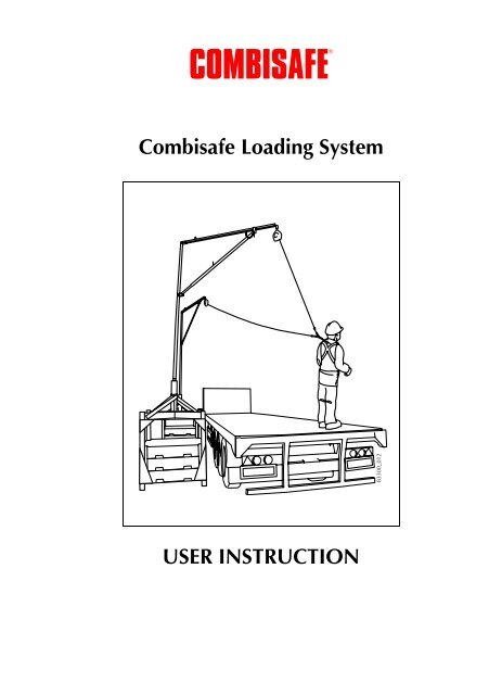
<strong>Combisafe</strong> <strong>Loading</strong> <strong>System</strong><br />
83300_012<br />
USER INSTRUCTION
Contents<br />
<strong>Combisafe</strong> <strong>Loading</strong> <strong>System</strong><br />
Contents<br />
GENERAL .................................................................................................... 3<br />
SAFETY INSTRUCTIONS ............................................................................. 4<br />
General information............................................................................... 4<br />
Always check products and equipment before use................................. 4<br />
Do not combine products ...................................................................... 4<br />
Always use personal fall arrest equipment.............................................. 5<br />
Inspection after a fall.............................................................................. 5<br />
Remember ............................................................................................. 5<br />
TECHNICAL DATA...................................................................................... 6<br />
Main parts.............................................................................................. 6<br />
ASSEMBLY .................................................................................................. 7<br />
Rigging .................................................................................................. 7<br />
Final Assembly..................................................................................... 12<br />
Safety check before initial use.............................................................. 12<br />
Check .................................................................................................. 13<br />
PFPE Guide.......................................................................................... 14<br />
20 ft long trailer (6,09 m) ............................................................... 14<br />
40 ft long trailer (12,18 m) ............................................................. 16<br />
Safety checks PFPE......................................................................... 17<br />
© <strong>Combisafe</strong> international AB - UI 83300-EN-0815<br />
Reservation for technical changes<br />
2
<strong>Combisafe</strong> <strong>Loading</strong> <strong>System</strong><br />
General<br />
General<br />
The <strong>Combisafe</strong> <strong>Loading</strong> <strong>System</strong> has been designed to allow the loading and<br />
unloading of equipment from the top of a flatbed delivery truck/trailer in a safe<br />
manner.<br />
The system stands approximately 6 metres in height to the anchor point position<br />
allowing the operative to work up to 5 metres in height from ground level with a<br />
working radius of up to 3.5 metres. Incorporated into the <strong>Combisafe</strong> <strong>Loading</strong><br />
<strong>System</strong> is a retractable fall arrest block which is anchored directly to the system's<br />
anchorage point and connected to the full body safety harness worn by the<br />
operative.<br />
Tested to prove compliance with EN 795 Class B standards, the <strong>Combisafe</strong><br />
<strong>Loading</strong> <strong>System</strong> can be used on a site or in a loading yard and can be moved to<br />
alternative locations as the needs arise. The <strong>Combisafe</strong> <strong>Loading</strong> <strong>System</strong><br />
incorporates an Alsipercha unit, which can be separated and folded up for ease of<br />
transport between locations.<br />
3
Safety instructions<br />
<strong>Combisafe</strong> <strong>Loading</strong> <strong>System</strong><br />
Safety instructions<br />
General information<br />
The <strong>Combisafe</strong> safe loading system is only intended for the purpose stated in this<br />
user instruction in preventing an operative from a fall incident when loading/<br />
unloading flatbed delivery vehicles.<br />
• Under no circumstances should the product be used as a makeshift crane or<br />
lifting/lowering device.<br />
• Under no circumstances should substitute items other than those provided<br />
with the system be used either in replacement or through preference as this<br />
may affect the performance of the product.<br />
• Care should be taken in the transportation of the product between uses and<br />
locations. If any damage occurs the item should be replaced.<br />
• The site location of the equipment should have in place a rescue plan, in the<br />
event of a fall arrest incident.<br />
• It is strongly recommended that a recovery line is attached to the retractable<br />
fall arrest block to enable the operative to pull the inertia reel down to their<br />
level to enable simple connection.<br />
Always check products and equipment before use<br />
Check all component parts of the <strong>Combisafe</strong> <strong>Loading</strong> <strong>System</strong> before installation.<br />
Never use damaged or rusty materials as this can affect safety.<br />
Do not combine products<br />
It is not recommended to install, combine or interconnect using products other<br />
than those supplied by COMBISAFE. <strong>Combisafe</strong> product responsibility is only<br />
valid with correctly rigged COMBISAFE products.<br />
4
<strong>Combisafe</strong> <strong>Loading</strong> <strong>System</strong><br />
Safety instructions<br />
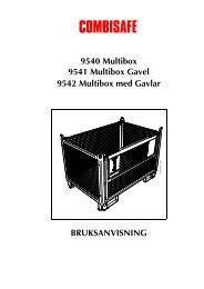
Always use personal fall arrest equipment<br />
Personal fall arrest equipment must always be worn during assembly and<br />
dismantling when a risk of falling exists. This also applies to work from e.g. a<br />
MEWP (mobile elevating working platform).<br />
1974_600<br />
Figure 1. Personal fall arrest equipment<br />
Inspection after a fall<br />
If a <strong>Combisafe</strong> <strong>Loading</strong> <strong>System</strong> has been used in anger e.g. a person falling. Then<br />
it should be removed from service and be inspected by a competent person.<br />
Contact <strong>Combisafe</strong> in the event of uncertainty.<br />
Remember<br />
• Plan the fall prevention at an early stage, this will benefit everyone.<br />
• Only use inspected safety products.<br />
• Restrict access below and around installation and working area to prevent<br />
injury to others from any fall hazard.<br />
• Use tools designed for the type of work to be carried out.<br />
• Check all clips are fixed correctly and straps are tightened securely.<br />
• Keep the installation area in order.<br />
• A safe workplace is an agreeable workplace.<br />
• Many fall accidents occur from a low height.<br />
5
Technical data<br />
<strong>Combisafe</strong> <strong>Loading</strong> <strong>System</strong><br />
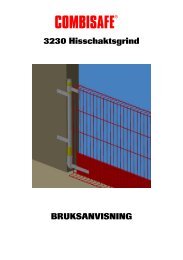
Main parts<br />
Technical data<br />
2500<br />
6<br />
5<br />
6120<br />
4<br />
3<br />
2<br />
1400<br />
1<br />
83300_001<br />
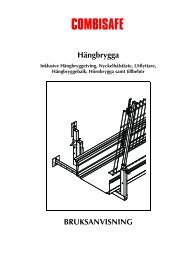
Figure 2. Main parts<br />
Item Description Weight<br />
1 Ballast (total) 3000 kg<br />
2 Base unit (Bottom Section) 221 kg<br />
3 Top section 276.3 kg<br />
4 Column Unit 25 kg<br />
5 Alsipercha Frame 82 kg<br />
6 Retractable fall arrest block 5.7 kg<br />
6
<strong>Combisafe</strong> <strong>Loading</strong> <strong>System</strong><br />
Assembly<br />
Assembly<br />
Rigging<br />
The following information and diagrams is a step by step guide to rigging one<br />
<strong>Combisafe</strong> loading system unit successfully. Before attempting the rigging of a<br />
<strong>Combisafe</strong> loading system unit, please make sure you have the following tools:<br />
• Hammer<br />
• Spirit Level<br />
• 36 mm spanners<br />
1. Adjust the feet to make the base unit level on the ground. The maximum<br />
inclination that the base unit can be placed upon is shown below.<br />
7°<br />
Figure 3. Maximum inclination<br />
2. Using a forklift truck Place the three 1000 kg concrete ballasts onto the base<br />
unit one after the other.<br />
83300_003<br />
83300_002<br />
Figure 4. Place the ballast<br />
7
Assembly<br />
<strong>Combisafe</strong> <strong>Loading</strong> <strong>System</strong><br />
3. Place the column unit through the column collar and into the centre of the<br />
top sections angle supports. This must be carried out using a safe means of<br />
access i.e. MEWP or fork lift basket.<br />
5<br />
4<br />
1<br />
2<br />
3<br />
83300_004<br />
1. Braces<br />
2. Centre of angle supports<br />
3. Column collar<br />
4. Column unit<br />
5. Conical tube<br />
6. Angle bracings<br />
Figure 5. Placing column<br />
6<br />
8
!83300_005<br />
<strong>Combisafe</strong> <strong>Loading</strong> <strong>System</strong><br />
Assembly<br />
4. The Alsipercha frame can now be lowered by a forklift truck or crane and<br />
slotted into the cone that is cast into the column unit until it is fully engaged<br />
in position. This must be carried out using a safe means of access i.e. MEWP<br />
or fork lift basket.<br />
NOTE<br />
After docking the frame to the column unit: Ensure the tie rope is fitted to<br />
the lengthener.<br />
Figure 6. Lower Alsipercha frame<br />
9
Assembly<br />
<strong>Combisafe</strong> <strong>Loading</strong> <strong>System</strong><br />
5. Using a forklift truck, place the forks underneath the top plate and lift top<br />
section (with the Alipercha frame included) over the top of the base unit and<br />
slowly lower the legs of the top plate into the legs of the base unit, using the<br />
leg guide to help them engage.<br />
NOTE<br />
The unit must be secured in one direction to prevent rotation. We Recommend<br />
that a rope is tied to the to the fall arrest block karabiner to enable<br />
the operative to retrieve the reel and allow simple connection to the operatives<br />
0.3 m extra webbing.<br />
3<br />
2<br />
1<br />
83300_006<br />
1. Bottom section<br />
2. Led guides<br />
3. Top section<br />
Figure 7. Lifting top selection on base unit<br />
10
<strong>Combisafe</strong> <strong>Loading</strong> <strong>System</strong><br />
Assembly<br />
6. Once in position the 26 mm holes in the top and bottom section should be<br />
aligned. Use M24x130 mm bolts and nuts to secure the two sections<br />
together.<br />
NOTE<br />
Risk of finger injury!<br />
83300_007<br />
Figure 8. Holes aligned<br />
NOTE<br />
• We recommend using Zinc coated full nuts throughout the system, and<br />
each one must be tighten up securely.<br />
• Always use PPE during assembly and disassembly of the <strong>Combisafe</strong> safe<br />
load system.<br />
11
Assembly<br />
<strong>Combisafe</strong> <strong>Loading</strong> <strong>System</strong><br />
Final Assembly<br />
83300_008<br />
Figure 9. Final assembly<br />
Safety check before initial use<br />
• Ensure unit is free to rotate.<br />
• Ensure the unit is perpendicular.<br />
• Final "brake" check of fall arrest block.<br />
12
<strong>Combisafe</strong> <strong>Loading</strong> <strong>System</strong><br />
Assembly<br />
Check<br />
Checking should be performed by a competent person. Checking includes:<br />
• Checks for weld damage of deformation.<br />
• Wear on retractable fall arrest block.<br />
• Nuts and bolts are secured properly.<br />
• Frame should be fully engaged in the in the cone inside the column unit.<br />
• Where the base is positioned directly onto the ground, as against on a concrete<br />
hard standing, sole plates of suitable size and strength to safely transmit and<br />
sustain a load of up to 2.0 tonnes should be placed under the adjustable feet<br />
of the base.<br />
13
Assembly<br />
<strong>Combisafe</strong> <strong>Loading</strong> <strong>System</strong><br />
PFPE Guide<br />
20 ft long trailer (6,09 m)<br />
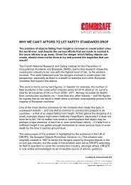
For unloading a 20 ft flatbed truck, only one <strong>Combisafe</strong> loading system is<br />
required. It needs to be positioned centrally to trailer at a minimum of 100 mm<br />
from the edge of the base to the edge of the trailer. As shown below:<br />
3000<br />
3000<br />
4<br />
3<br />
2400<br />
2<br />
100<br />
[mm]<br />
1<br />
83300_009<br />
1. <strong>Combisafe</strong> loading system unit<br />
2. Alsipercha frame<br />
3. 6,3 inertia reel<br />
4. Operative<br />
Figure 10. 20 ft trailer<br />
14
<strong>Combisafe</strong> <strong>Loading</strong> <strong>System</strong><br />
Assembly<br />
Any operative unloading a 20 ft flatbed trailer should be wearing:<br />
• appropriate footwear<br />
• reflective vest and helmet with chin strap<br />
• fully body harness<br />
• extra webbing 0,3 m for extended back anchorage.<br />
Once an operative is wearing the correct PFPE they can then attach the extra<br />
0,3 m webbing to the harness by looping it through itself, and then attach the<br />
other end of the extra 0,3 m webbing to the retractable fall arrest block, using a<br />
Karabiner fixing.<br />
NOTE<br />
• The retractable fall arrest block should consist of a 6,3 m inertia reel.<br />
• The operative must be connected to the system before accessing the<br />
flatbed.<br />
15
Assembly<br />
<strong>Combisafe</strong> <strong>Loading</strong> <strong>System</strong><br />
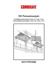
40 ft long trailer (12,18 m)<br />
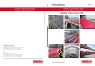
As can be seen from the image below, when loading/unloading a 40 ft trailer, two<br />
<strong>Combisafe</strong> loading systems are required to work in together.<br />
• The edge of each base remains at 100 mm from the edge of the trailer.<br />
• The operative should be connected to both the Alsipercha frames. This helps<br />
to control the movement of the operative on the 12 m long flatbed in the event<br />
of a fall.<br />
• If access to the extreme outside corners of the flatbed is required it is<br />
recommended that the trailer is moved to accommodate safe access within the<br />
3,5 m working radius of the frame.<br />
3100<br />
6000 3100<br />
4<br />
3<br />
2400<br />
2<br />
100<br />
[mm]<br />
4600<br />
1<br />
83300_010<br />
1. <strong>Combisafe</strong> loading system unit<br />
2. Alsipercha frame<br />
3. 10 m inertia reel<br />
4. Operative<br />
Figure 11. 40 ft trailer<br />
16
<strong>Combisafe</strong> <strong>Loading</strong> <strong>System</strong><br />
Assembly<br />
Any operative unloading a 40 ft flatbed trailer should be wearing:<br />
• Appropriate footwear<br />
• Reflective Vest and helmet with chin strap<br />
• Fully Body Harness<br />
• Extra Webbing 0.3m for extended back anchorage<br />
Once an operative is wearing then the correct PFPE they can then attach the extra<br />
0.3m webbing to the harness by looping it through itself, and then attach the other<br />
end of the extra 0.3m webbing to both retractable fall arrest blocks from each<br />
system, using a Karabiner fixing.<br />
NOTE<br />
• The retractable fall arrest block should consist of a 10 m inertia reel to<br />
allow the operative to move freely to the far extents of the trailer.<br />
• The operative must be connected to both systems before accessing the<br />
flatbed.<br />
Safety checks PFPE<br />
Safety Checks for PFPE include:<br />
• Wear on retractable fall arrest block.<br />
• Check that the reel engages when pulled.<br />
• Karabiners are full tightened before using the system.<br />
• All straps on body harness are tightened securely.<br />
17
Assembly<br />
<strong>Combisafe</strong> <strong>Loading</strong> <strong>System</strong><br />
18
<strong>Combisafe</strong> <strong>Loading</strong> <strong>System</strong><br />
Assembly<br />
19
®<br />
COMBISAFE<br />
<strong>Combisafe</strong> International AB<br />
www.combisafe.com