DC/DC CONVERTER
DC/DC CONVERTER
DC/DC CONVERTER

Create successful ePaper yourself
Turn your PDF publications into a flip-book with our unique Google optimized e-Paper software.
<strong>DC</strong>/<strong>DC</strong> <strong>CONVERTER</strong><br />
Thermal Management<br />
Application<br />
notes<br />
Thermal Management<br />
1- Introduction<br />
This application note discusses thermal management<br />
of GAIA Converter <strong>DC</strong>/<strong>DC</strong> modules.<br />
As with any power electronic circuitry, <strong>DC</strong>/<strong>DC</strong><br />
converter do not transform all input power to<br />
output power; a portion of input power is<br />
dissipated as heat. The amount of heat<br />
dissipated is dependent on the output load<br />
and converter efficiency. The control and<br />
evacuation this heat is called thermal management.<br />
Reasons for thermal management include :<br />
• Maintain <strong>DC</strong>/<strong>DC</strong> converter case<br />
temperature below maximum admissible<br />
temperature<br />
• Improve reliabilty (MTBF)<br />
• Maximize efficiency<br />
• Utilize maximum available output power<br />
Prudent thermal management will result in long<br />
term reliable operation and allow maximum<br />
power utilization in a minimum amount of<br />
space.Power<br />
1-1 Power Dissipation in the <strong>DC</strong>/<strong>DC</strong><br />
pation & Efficiency<br />
To calculate how much power is dissipated in<br />
the converter, input voltage, output power<br />
together with <strong>DC</strong>/<strong>DC</strong> converter efficiency must<br />
be known.<br />
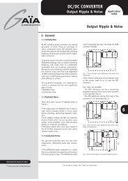
GAIA Converter gives for any converter the<br />
efficiency profiles depending on input and<br />
output load as follow (ex : MGDS-10-J-F).<br />
Efficiency (%)<br />
86<br />
83<br />
80<br />
77<br />
74<br />
71<br />
68<br />
Figure 9 : Typical efficiency versus load<br />
at various input<br />
input 28V<br />
input 16V<br />
input 40V<br />
2.5 5 7.5 10<br />
Output Power (W) (MGDS-10-J-F module)<br />
Example : the power dissipated in this MGDS-<br />
10-J-F module at 28Vdc input voltage and used<br />
at full load power 10W is : (From the MGDM-10<br />
datasheet–page 4 precedent curve : the<br />
efficiency of this module at full load 10W and<br />
28 Vdc input voltage is 86%).<br />
The power dissipation is a function of the power<br />
used and <strong>DC</strong>/<strong>DC</strong> converter efficiency :<br />
Pdiss = (Pused/Efficiency - Pused)<br />
In this example we find : Pdiss=1,6 W<br />
This power dissipated is transformed into heat.<br />
1-2 Heat Transfer<br />
The primary goal in the thermal design is to<br />
predict and control the converter’s heat so that<br />
it does not exceed the maximum rating of<br />
temperature admissible by the <strong>DC</strong>/<strong>DC</strong><br />
converter.<br />
Heat energy is transferred from regions of high<br />
temperature to regions of low temperature via<br />
three basic mechanisms :<br />
• radiation : electromagnetic transfer of<br />
heat between masses at different<br />
temperatures<br />
• conduction : transfer of heat through a<br />
solid medium (heatsink for example)<br />
• convection : transfer of heat through the<br />
medium of fluid (typically air from ventilation).<br />
All three of these heat transfer mechanisms<br />
are active to some degree in every application.<br />
All three of these mechanism should be<br />
given consideration when developping thermal<br />
management.<br />
6<br />
REDEFINING THE SOURCE OF POWER<br />
© Gaia Converter FC03-029.08/04 Revision B<br />
For locations, phone, fax, E-Mail see back cover
Thermal Management<br />
Application<br />
notes<br />
2-Radiation Transfer<br />
Thermal radiation is the transfer of heat by electromagnetic<br />
radiation (primarily in the infra-red wavelengths). Radiation<br />
is the only means of heat transfer between bodies<br />
separated by a complete space vacuum.<br />
Many factors contribute to thermal radiation efficiency,<br />
such as temperature differentials, surface area, and surface<br />
emissivity.<br />
Black anodized aluminum is a good thermal medium to<br />
take advantage of radiated heat.<br />
A heatsink with a large area for a given volume will take<br />
maximum advantage of radiation.<br />
But radiation is a minor contributor to the overall thermal<br />
link in most power converter applications and counts in<br />
majority of cases for less than 5% of total heat transfer.<br />
It is best to use the effects of radiation as a «safety<br />
margin» in the thermal design, since its contributions to<br />
heat transfer will normally be small, is difficult to quantify,<br />
and requires a relatively larger heatsink area to be efficient.<br />
3-Conduction Transfer<br />
3-1 General<br />
Heat is transferred through a solid medium by conduction<br />
and it is the most fundamental of all thermal mechanisms.<br />
Thermal conduction can be understood as analog as<br />
conduction of electrical current in a wire. As the electrical<br />
current in a wire is a function of the different electrical<br />
resistances and the voltage drop, the thermal transfer is<br />
a function of the different thermal resistances and<br />
temperature drop from one point to another.<br />
This helpfull modelisation can be depicted as follow :<br />
Tbaseplate<br />
Pdiss<br />
Rth<br />
Rth<br />
Tbaseplate<br />
Tambient<br />
Tambient<br />
resistance values are given thereafter including <strong>DC</strong>/<strong>DC</strong><br />
converter values from GAIA Converter, heatsink thermal<br />
resistance values from manufacturers like Thermalloy,<br />
Fisher Elektronik, ThermaFlo, Radian etc .....<br />
Type of Product<br />
GAIA Converter MGDS-10 <strong>DC</strong>/<strong>DC</strong> converter series<br />
GAIA Converter MGDS-20 <strong>DC</strong>/<strong>DC</strong> converter series<br />
Voltage interruption :<br />
Thermalloy heatsink 0 V<strong>DC</strong> type 6512B<br />
Thermalloy heatsink type 6516B<br />
Fisher Elektronik heatsink type SK <strong>DC</strong> 5 1 59 SA<br />
Fischer Elektronik heatsink type SK <strong>DC</strong> 5 59 SA<br />
ThermaFlo heatsink type 423000B00000<br />
Radian heatsink HS1579EX<br />
Thermal<br />
Resistance<br />
12 °C/W<br />
7 °C/W<br />
9,1 °C/W<br />
4,4 °C/W<br />
3,9 °C/W<br />
4,1 °C/W<br />
4,67 °C/W<br />
4,5°C/W<br />
3-3 Thermal Resistance for Interface Membrane Path<br />
An interface thermal resistance path is present at the<br />
junction of each conductive media (e.g., between baseplate<br />
and heatsink). It is important for the media to maintain<br />
close intimate contact with each other to minimize thermal<br />
resistance. The thermal resistance of still air is very<br />
high ... more than 5000 times that of aluminum. An air<br />
gap of 10 mils across an area of (2" x 2") would yield a<br />
thermal resistance of 3.5 °C / W, significantly reducing<br />
the effectiveness of the mating heatsink . When attaching<br />
a heatsink to the converter, an attempt should be made<br />
to minimize the global thermal resistance by using thermal<br />
membrane in between the baseplate and the heatsink. the<br />
following guidelines should be observed :<br />
• Maintain flat and smooth surfaces.<br />
• Torque fasteners (if used) according to fastener size/<br />
type to optimize clamping pressure (i.e between 25<br />
and 100 psi).<br />
The thermal resitivity of a uniform conducting membrane<br />
can be defined as: Rth = L / K x A<br />
where :<br />
Rth = Thermal Resistance (°C / watt)<br />
L = Length or width (inch) or (mm)<br />
A = Cross Sectional Area (inch2) or (mm2)<br />
K = Material Thermal Conductivity (watt/inch°C or mm°C)<br />
K is an accessible value given by manufacturers; but<br />
manufacturers are given also the thermal impedance wich<br />
is the thermal resistance by surface unit which is more<br />
easy for calculation. Examples of thermal pad values are<br />
given thereafter from Bergquist manufacturer.<br />
6<br />
3-2 Thermal Resistance for Heatsink, <strong>DC</strong>/<strong>DC</strong> Converter<br />
Thermal resistance are accessible values (defined in °C/<br />
W) given by majority of <strong>DC</strong>/<strong>DC</strong> converter manufacturers or<br />
heatsink manufacturers. Some examples of thermal<br />
Type of Thermal Pad Interface<br />
Bergquist «Silpad 400» 0.009 width, 50psi<br />
Bergquist «Silpad 900S» 50 psi<br />
Voltage interruption :<br />
Bergquist «Hi-Flow<br />
0 V<strong>DC</strong><br />
625, 50 psi<br />
Thermal Impedance<br />
1,45 °C-inch2/W<br />
0,61 °C-inch2/W<br />
0,7 °C-inch2/W<br />
© Gaia Converter FC03-029.08/04 Revision B<br />
For locations, phone, fax, E-Mail see back cover<br />
2
Thermal Management<br />
Application<br />
notes<br />
4-Convection Transfer<br />
Heat transfer by Convection (Natural or Forced) involves<br />
the transfer of heat to a surrounding fluid by conduction,<br />
typically air. This mode of heat transfer is dependent on a<br />
number of variables and is somewhat complex to calculate.<br />
Surface area, temperature gradient, thermal conductivity<br />
of fluid (air), velocity of fluid (air), fluid (air) density and<br />
other variables affect convection.<br />
4-1 Natural Convection<br />
Natural convection is sometimes also referred as Free convection.<br />
Natural convection is easier to implement than<br />
forced convection, but at the expense of increased thermal<br />
resistance.<br />
Natural convection produces its own air velocity, due to<br />
the local heating of air at the heatsink surface. The air<br />
density is reduced when heated, causing it to rise, thus<br />
causing the air movement.<br />
Natural Convection is not as effective at higher altitudes<br />
due to air density reduction.<br />
«Free air» movement across a thermal dissipator is required<br />
to perform adequately.<br />
«confined air» would not conduct to natural convection.<br />
This would occur with a converter mounted (without thermal<br />
contact) within an enclosed box.<br />
To maximize the transfer of heat by natural convection<br />
the following rules apply :<br />
• Mount heat sinks so the maximum length of convection<br />
surfaces (fins) are in the vertical plane.<br />
• Place the heat sink above the converter, allowing air<br />
to rise above.<br />
• Provide sufficient enclosure ventilation for natural<br />
convection of the air.<br />
• Note that close heatsink fin spacing will reduce the<br />
effectiveness of the heatsink.<br />
Due to the complexity to calculate heat transfer for only<br />
free air convection, majority of <strong>DC</strong>/<strong>DC</strong> converter<br />
manufacturers or heatsink manufacturers are given their<br />
thermal resistance performances in free air convection<br />
condition (which will then include conduction and natural<br />
convection).<br />
If thermal resistance is given in confined air it will give a<br />
margin if the <strong>DC</strong>/<strong>DC</strong> converter is used in natural convection<br />
environment.<br />
From the previous table in section 3-2 we can complete<br />
our discussion by adding the convection condition :<br />
Type of Product<br />
GAIA Converter MGDS-10 <strong>DC</strong>/<strong>DC</strong> converter series<br />
12 °C/W<br />
GAIA Converter MGDS-20 <strong>DC</strong>/<strong>DC</strong> converter series<br />
Voltage interruption :<br />
7 °C/W<br />
Thermalloy heatsink 0 V<strong>DC</strong> type 6512B<br />
9,1 °C/W<br />
Thermalloy heatsink type 6516B<br />
4,4 °C/W<br />
Fisher Elektronik heatsink type SK <strong>DC</strong> 5 1 59 SA<br />
3,9 °C/W<br />
Fischer Elektronik heatsink type SK <strong>DC</strong> 5 59 SA<br />
4,1 °C/W<br />
ThermaFlo heatsink type 423000B00000<br />
4,67 °C/W<br />
Radian heatsink HS1579EX<br />
4,5°C/W<br />
© Gaia Converter FC03-029.08/04 Revision B<br />
Thermal<br />
Resistance<br />
Convection<br />
Condition<br />
Free convection<br />
Free convection<br />
Free convection<br />
Free convection<br />
Free convection<br />
Free convection<br />
Free convection<br />
Free convection<br />
4-2 Forced Convection<br />
For locations, phone, fax, E-Mail see back cover<br />
Forced convection implies the use of fans to increase the<br />
air movement across the heatsink area. Heatsink to air<br />
thermal resistivity can be improved by as much as a factor<br />
of 10 when compared to natural convection.<br />
This may be the way to go when operating at high ambient<br />
temperatures, operating at high power levels, or when<br />
space is at a premium. Of course fans are not without<br />
their problems. They are noisy, and in dirty environments<br />
they often require filters.<br />
They can also cause an unreliable power system if the<br />
filters are not changed frequently or the fan itself fails.<br />
Therefore proper care must be exercised when fans are<br />
used.<br />
Airflow specification is usually given as a function of air<br />
velocity in linear feet per minute LFM (or m/s). Fan<br />
specifications are usually given as a function of air volume<br />
in cubic feet per minute (CFM). Conversion from volume<br />
to velocity is as follows :<br />
Velocity (LFM) = Volume (CFM) / Area<br />
Area is the cross sectional area through which the air<br />
passes.<br />
An amount of airflow (400ft/min or 2 m/s) will have a<br />
significant impact to improve heat transfer thru convection.<br />
Airflow above 1000ft/min does not significantly<br />
improve heat transfer.<br />
To maximize the transfer of heat by forced convection the<br />
following rules apply :<br />
• Keep low power components upstream<br />
• Space heatsink fins closer together than in a Natural<br />
Convection design.<br />
• Channel the flow of the air through the spaces<br />
between the fins of the heat sink.<br />
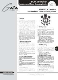
Due to the complexity to calculate heat transfer for only<br />
forced air cooling, it is best to use the thermal resistance<br />
data supplied by various heatsink vendors. Heatsink vendors<br />
will either plot thermal resistance vs air velocity or plot<br />
temperature rise vs power dissipation for various air<br />
velocities : the thermal resistance will then include<br />
conduction in forced convection cooling.<br />
An example is given thereafter :<br />
Thermal resistance as a function of air velicity<br />
Air Velocity in m/s<br />
6<br />
3
Thermal Management<br />
Application<br />
notes<br />
4 Global Thermal Model<br />
An equivalent global thermal circuit model for the converter<br />
is shown in Figure herafter. The relationship between<br />
Temperature Rise (DT), Thermal Resistivity (Rth) and Power<br />
Dissipation (Pdiss) may be stated as follows:<br />
Rth = DT / Pdiss<br />
The basic thermal model is analogous to Ohm’s Law as<br />
shown in Table 1. This basic model is used to determine<br />
the converter’s baseplate temperature rise (above ambient)<br />
as a function of converter power dissipation and the thermal<br />
resistance path from case to ambient.<br />
Thermal Model Electrical Equivalent :<br />
Temperature Rise (DT ) Voltage (V)<br />
Power Dissipation (Pdiss ) Current (I)<br />
Thermal Resistance (Rth) Electrical Resistance (R)<br />
The thermal resistance (Rth(b-a) ) is the sum of all thermal<br />
resistances in the thermal path from baseplate to<br />
ambient.<br />
When a heatsink is attached to the converter baseplate,<br />
two distinct thermal resistance paths must be added :<br />
Rth(b-a) = Rth(b-h) + Rth(h-a)<br />
Rth(b-a) = Thermal Resistance - Baseplate to Ambient (°C / W)<br />
Rth(b-h) = Thermal Resistance - Baseplate to Heatsink (°C / W)<br />
Rth(h-a) = Thermal Resistance - Heatsink to Ambient (°C / W)<br />
Any additional thermal resistance paths must be added to<br />
the total thermal resistance calculation. An application<br />
which conducts heat from the converter baseplate to a<br />
remote dissipating surface through a thermally conductive<br />
member would add two additional paths to the total :<br />
Rth(b-a) = Rth(b-m) + Rth(m-h) + Rth(h-a)<br />
Tbaseplate<br />
Rth(b-m) Rth(m-h) Rth(h-a)<br />
Tambient<br />
Rth(b-a) = Thermal Resistance - Baseplate to Ambient (°C / W)<br />
Rth(b-m) = Thermal Resistance - Baseplate to Member (°C / W)<br />
Pdiss<br />
Rth(m-h) = Thermal Resistance - Member to Heatsink (°C / W)<br />
Rth(h-a) = Thermal Resistance - Heatsink to Ambient (°C / W)<br />
4-1 Global Thermal Resistance<br />
The baseplate to ambient thermal resistance Rth(b-a) can<br />
vary greatly depending on the heat transfer method and<br />
configuration.<br />
As indicated in the MGDM-150 data sheet, Rth(b-a) can<br />
vary from 1.5 to 8°C/W.<br />
This number reflects a typical range of cooling configurations<br />
from Forced Air Convection to Natural (Free) Air Convection<br />
with and without heatsink.<br />
Adding a heat sink to the thermal path produces an added<br />
thermal resistance Rth(b-h) to the total path.<br />
Heat (due to power dissipation) is removed from the metal<br />
baseplate of the converter to its surrounding environment.<br />
There are 3 basic thermal mechanisms :<br />
to transfer heat:<br />
• Conduction<br />
• Convection (Natural & Forced)<br />
• Radiation<br />
In most applications heat is removed by a combination of<br />
all mechanisms. The Thermal Resistance in the above model<br />
is a measure of the ability of all combined thermal<br />
mechanisms to transfer heat away from the converter’s<br />
baseplate.<br />
A higher Thermal Conductivity will result in a lower thermal<br />
Resistance, hence a lower baseplate temperature rise.<br />
6<br />
© Gaia Converter FC03-029.08/04 Revision B<br />
For locations, phone, fax, E-Mail see back cover<br />
4
For more detailed specifications and applications information, contact :<br />
International Headquarters<br />
GAÏA Converter - France<br />
ZI de la Morandière<br />
33185 LE HAILLAN - FRANCE<br />
Tel. : + (33)-5-57-92-12-80<br />
Fax : + (33)-5-57-92-12-89<br />
Represented by :<br />
North American Headquarters<br />
GAÏA Converter Canada, Inc<br />
4038 Le Corbusier Blvd<br />
LAVAL, QUEBEC - CANADA H7L 5R2<br />
Tel. : (514)-333-3169<br />
Fax : (514)-333-4519<br />
Printed in France by GAIA Converter Gaia Converter FC03-029.08/04 Revision B. Graphisme : Philippe Clicq<br />
Information given in this datasheet is believed to be accurate and reliable. However, no responsibility is assumed for the consequence of its use nor for any infringement of patents or other rights of third parties which may result from its use.<br />
These products are sold only according to GAIA Converter general conditions of sale, unless otherwise confirmed by writing. Specifications subject to change without notice.