DC/DC CONVERTER Output Ripple & Noise
DC/DC CONVERTER Output Ripple & Noise
DC/DC CONVERTER Output Ripple & Noise

Create successful ePaper yourself
Turn your PDF publications into a flip-book with our unique Google optimized e-Paper software.
<strong>Output</strong> <strong>Ripple</strong> & <strong>Noise</strong><br />
Application<br />
notes<br />
The conducted mode noise is due to common mode currents<br />
being pumped through parasitic capacitances (Cpt),<br />
generally less than a picofarad<br />
These parasitic capacitances, which depend mainly on the<br />
dielectric constant substrate, are proportional to the area<br />
used and inversely proportional to the substrate thickness.<br />
The common mode noise can have a magnitude of several<br />
volts.<br />
The common mode noise can interfere with the differential<br />
mode noise. It will result that common mode noise appears<br />
as differential mode noise and can cause misleading<br />
differential mode noise measurements. So the common<br />
mode noise spectrum magnitude has to be reduced before<br />
making differential mode noise measurements. The best<br />
way to suppress the common mode output noise is to<br />
shunt the power path to case parasitic capacitances.<br />
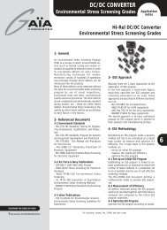
2- Measurements<br />
2-1 Measurement of Radiated <strong>Noise</strong><br />
Measurement of the radiated noise component, that<br />
requires specific and heavy equipments, is not described<br />
in this application note.<br />
2-2 Measurement of <strong>Output</strong> Conducted <strong>Noise</strong><br />
Fig 4 : Connection type to check output common mode<br />
2-2-2 Measurement of Differential Mode<br />
To measure differential mode noise, you must reduce the<br />
interferences of the other modes. There are two reliable<br />
ways to measure only differential mode:<br />
- The first way is to short out the input and the output<br />
from Gi to the return lead Go to ground with a high freqency<br />
capacitance (fig 5: CHF and CHF2)<br />
Conducted output noise voltage measurements are difficult<br />
to make even under the best conditions.<br />
Depending on the technic used, results may vary widely.<br />
An oscilloscope with a differential mode bandwidth of<br />
100 MHz or more is usually used to make noise<br />
measurements.<br />
It should be noted, that oscillocope have a finite ability to<br />
reject common mode signals, and these signals can be<br />
worsened by the use of long ground leads on the scope.<br />
Long ground leads adversely impact the common-mode<br />
rejection capability of oscilloscopes because the ground<br />
leads have an inductance not present on the signal lead.<br />
These differing impedances take common-mode noises and<br />
interfere with the differential mode signals that show up<br />
on the trace.<br />
The differential mode noise measurement must be carried<br />
out at the outputs of the converter to reduce the pick up<br />
of radiated noise.<br />
Leads lengths, including the ground must be as short as<br />
possible to reduce the pick up of radiated noise.<br />
2-2-1 Measurement of Common Mode :<br />
To measure the common-mode noise, put the scope probe<br />
on the ground lead connection of the probe while the<br />
ground lead is tied to either output return Go or positve<br />
output Vo (Fig 4). If the noise is common-mode, you will<br />
still see «noise» even though you are looking at the same<br />
point<br />
Fig 5 : Capabilities of HF capacitance connections for measuring output differential<br />
mode<br />
- The second way is to connect high frequency<br />
capacitances to short out the parasitic capacitances (fig<br />
6: CHF2 and CHF3) from Gi to case and from Go to case.<br />
Fig 6: Capabilities of HF capacitance connections for measuring output differential<br />
noise<br />
6<br />
© Gaia Converter FC97-013.08/04 Revision C<br />
For locations, phone, fax, E-Mail see back cover<br />
2