DC/DC CONVERTER Output Ripple & Noise
DC/DC CONVERTER Output Ripple & Noise
DC/DC CONVERTER Output Ripple & Noise

Create successful ePaper yourself
Turn your PDF publications into a flip-book with our unique Google optimized e-Paper software.
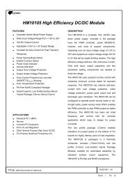
<strong>DC</strong>/<strong>DC</strong> <strong>CONVERTER</strong><br />
<strong>Output</strong> <strong>Ripple</strong> & <strong>Noise</strong><br />
Application<br />
notes<br />
<strong>Output</strong> <strong>Ripple</strong> & <strong>Noise</strong><br />
1- General<br />
1-1 Introduction<br />
<strong>DC</strong>/<strong>DC</strong> switching power converters are natural<br />
generators of noise. There are two types of<br />
noise: conducted noise and radiated noise<br />
which are present at the fundamental switching<br />
frequency of the power converter and its higher<br />
order harmonics.<br />
In general, power converters using Pulse Widht<br />
Modulated topology, have a constant switching<br />
frequency, wich create noise in a predictable<br />
bandwidth that can facilitate attenuation.<br />
Resonant or zero switching converters generate<br />
less intrinsic noise, but their load dependant<br />
variable switching frequencies tend to generate<br />
noise over a wide frequency excursions, making<br />
them difficult to control.<br />
For any kind of converters, it is important to<br />
control or measure the two most significant<br />
type of noise:<br />
• Radiated noise<br />
• Conducted noise<br />
1-2 Radiated <strong>Noise</strong><br />
There are 3 main sources of radiated noise as<br />
follows :<br />
• The major cause of radiated noise is due to<br />
high current change (di/dt) in circuit leads<br />
during switching, generating magnetic radiation.<br />
• Fast voltage changes (dv/dt) can generate<br />
electric-fields which do not usually cause<br />
system noise problems since they decrease<br />
quickly as a function of distance.<br />
• The other effects that occur, are a result of<br />
the 50-70 MHz component on the main switch<br />
common mode noise.<br />
1-3 Conducted <strong>Noise</strong><br />
The spectral conducted noise has two main<br />
components: differential mode and common<br />
mode.<br />
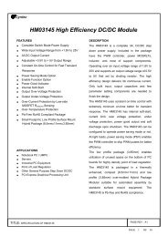
• The differential mode component is a mode<br />
that occurs between the output Vo and its return<br />
line Go as shown in fig 1. The differential mode<br />
noise is generally less than 150 mVpp for GAÏA<br />
converter modules<br />
Fig 1 : Power converter output differential noise model with<br />
isolated case<br />
• The common mode noise occurs between each<br />
of the output leads Vo or Go and the EMI<br />
reference.<br />
Two cases are possible:<br />
- The EMI reference can be a measuring<br />
equipment ground if the case of the converter<br />
is not grounded (fig 2).<br />
- The EMI reference can be the case of the<br />
converter if it is grounded (fig 3).<br />
Fig 2 : Power converter output differential and common noise<br />
model with isolated case.<br />
Fig 3 : Power converter output noise model with ground-case link<br />
6<br />
REDEFINING THE SOURCE OF POWER<br />
© Gaia Converter FC97-013.08/04 Revision C<br />
For locations, phone, fax, E-Mail see back cover
<strong>Output</strong> <strong>Ripple</strong> & <strong>Noise</strong><br />
Application<br />
notes<br />
The conducted mode noise is due to common mode currents<br />
being pumped through parasitic capacitances (Cpt),<br />
generally less than a picofarad<br />
These parasitic capacitances, which depend mainly on the<br />
dielectric constant substrate, are proportional to the area<br />
used and inversely proportional to the substrate thickness.<br />
The common mode noise can have a magnitude of several<br />
volts.<br />
The common mode noise can interfere with the differential<br />
mode noise. It will result that common mode noise appears<br />
as differential mode noise and can cause misleading<br />
differential mode noise measurements. So the common<br />
mode noise spectrum magnitude has to be reduced before<br />
making differential mode noise measurements. The best<br />
way to suppress the common mode output noise is to<br />
shunt the power path to case parasitic capacitances.<br />
2- Measurements<br />
2-1 Measurement of Radiated <strong>Noise</strong><br />
Measurement of the radiated noise component, that<br />
requires specific and heavy equipments, is not described<br />
in this application note.<br />
2-2 Measurement of <strong>Output</strong> Conducted <strong>Noise</strong><br />
Fig 4 : Connection type to check output common mode<br />
2-2-2 Measurement of Differential Mode<br />
To measure differential mode noise, you must reduce the<br />
interferences of the other modes. There are two reliable<br />
ways to measure only differential mode:<br />
- The first way is to short out the input and the output<br />
from Gi to the return lead Go to ground with a high freqency<br />
capacitance (fig 5: CHF and CHF2)<br />
Conducted output noise voltage measurements are difficult<br />
to make even under the best conditions.<br />
Depending on the technic used, results may vary widely.<br />
An oscilloscope with a differential mode bandwidth of<br />
100 MHz or more is usually used to make noise<br />
measurements.<br />
It should be noted, that oscillocope have a finite ability to<br />
reject common mode signals, and these signals can be<br />
worsened by the use of long ground leads on the scope.<br />
Long ground leads adversely impact the common-mode<br />
rejection capability of oscilloscopes because the ground<br />
leads have an inductance not present on the signal lead.<br />
These differing impedances take common-mode noises and<br />
interfere with the differential mode signals that show up<br />
on the trace.<br />
The differential mode noise measurement must be carried<br />
out at the outputs of the converter to reduce the pick up<br />
of radiated noise.<br />
Leads lengths, including the ground must be as short as<br />
possible to reduce the pick up of radiated noise.<br />
2-2-1 Measurement of Common Mode :<br />
To measure the common-mode noise, put the scope probe<br />
on the ground lead connection of the probe while the<br />
ground lead is tied to either output return Go or positve<br />
output Vo (Fig 4). If the noise is common-mode, you will<br />
still see «noise» even though you are looking at the same<br />
point<br />
Fig 5 : Capabilities of HF capacitance connections for measuring output differential<br />
mode<br />
- The second way is to connect high frequency<br />
capacitances to short out the parasitic capacitances (fig<br />
6: CHF2 and CHF3) from Gi to case and from Go to case.<br />
Fig 6: Capabilities of HF capacitance connections for measuring output differential<br />
noise<br />
6<br />
© Gaia Converter FC97-013.08/04 Revision C<br />
For locations, phone, fax, E-Mail see back cover<br />
2
<strong>Output</strong> <strong>Ripple</strong> & <strong>Noise</strong><br />
Application<br />
notes<br />
We recommend to use high frequency capacitances > 10nF<br />
and the connection leads should be as short as possible.<br />
To make the measurement you must carry out the scope<br />
probe on Vo and the probe ground on Go as described in<br />
fig.7.<br />
GAÏA Converter recommend capacitors with low Equivalent<br />
Series Resistor (ESR) and low Equivalent Series Inductance<br />
(ESL) over the frequency band being filtered to<br />
make the attenuation vs frequency predictable.<br />
We recommend to place a capacitance (fig 8:C1) from the<br />
input and the output ground of the converter. These connections<br />
will shunt the Common-Mode current before it<br />
comes in (for the input) and comes out (for the output).<br />
The higher the switching frequency, the closer the<br />
capacitance must be placed.<br />
3-2 Filtering of Conducted Differential Mode<br />
To reduce the output differential mode noise, capacitances<br />
and inductances are necessary. An LC filter (fig 8) is<br />
recommended. GAÏA Converter recommends the following<br />
schematic (fig 8) for its <strong>DC</strong>/<strong>DC</strong> converters.<br />
This recommended filter will reduce the output differential<br />
noise well below the most stringent requirements.<br />
Fig 7: Connection type to measure output differential mode<br />
GAÏA Converter modules integrate an efficient filter to<br />
reduce output noise. If the internal EMI filter dedicated<br />
to the output is not sufficient to bring the noise levels<br />
within your system requirements, external LC unit may be<br />
added on the output.<br />
3- Filtering<br />
Fig 8/ Diagram connection for common and differential mode<br />
3-1 Filtering of Conducted Common Mode<br />
To filter the conducted mode, capacitors are sufficient.<br />
C1<br />
L<br />
C2<br />
: Common mode noise capacitance 10nF<br />
: Equivalent inductance for differential mode 2.2µH<br />
type Murata LQH32CN2R2M23<br />
: Capacitance 33µF tantalum SMD 293D type<br />
6<br />
© Gaia Converter FC97-013.08/04 Revision C<br />
For locations, phone, fax, E-Mail see back cover<br />
3
For more detailed specifications and applications information, contact :<br />
International Headquarters<br />
GAÏA Converter - France<br />
ZI de la Morandière<br />
33185 LE HAILLAN - FRANCE<br />
Tel. : + (33)-5-57-92-12-80<br />
Fax : + (33)-5-57-92-12-89<br />
Represented by :<br />
North American Headquarters<br />
GAÏA Converter Canada, Inc<br />
4038 Le Corbusier Blvd<br />
LAVAL, QUEBEC - CANADA H7L 5R2<br />
Tel. : (514)-333-3169<br />
Fax : (514)-333-4519<br />
Information given in this datasheet is believed to be accurate and reliable. However, no responsibility is assumed for the consequence of its use nor for any infringement of patents or other rights of third parties which may result from its use.<br />
These products are sold only according to GAIA Converter general conditions of sale, unless otherwise confirmed by writing. Specifications subject to change without notice.<br />
Printed in France by GAIA Converter Gaia Converter FC97-013.08/04 Revision C. Graphisme : Philippe Clicq