HM03145 High Efficiency DC/DC Module
HM03145 High Efficiency DC/DC Module
HM03145 High Efficiency DC/DC Module

You also want an ePaper? Increase the reach of your titles
YUMPU automatically turns print PDFs into web optimized ePapers that Google loves.
APPLICATION INFORMATION<br />
At this point the output under-voltage and<br />
power good circuitry is enabled. There is<br />
100mV of hysterics built into the UVLO circuit<br />
and when PVCC falls to 4.1V (nom.) the<br />
output drivers are shut down and tri-stated.<br />
shown below:<br />
Inductor<br />
current<br />
Time<br />
I PEAK<br />
I OUT<br />
I LIMIT<br />
Current Limit<br />
Current limiting of the <strong>HM03145</strong> can be<br />
accomplished by sensing voltage for on-state<br />
resistance of low-side MOSFET. R DS(ON)<br />
sensing is more efficient and less expensive.<br />
R SEN resistor between the ISEN pin and Phase<br />
pin sets the over current threshold. This<br />
resistor R SEN is connected to a 10μA current<br />
source within the module which is turned on<br />
when the low side MOSFET turns on. When<br />
the voltage drop across the low side MOSFET<br />
equals the voltage across the R SEN resistor,<br />
positive current limit will activate. The high<br />
side MOSFET will not be turned on until the<br />
voltage drop across the low-side MOSFET<br />
falls below the voltage across the R SEN resistor.<br />
In an extreme over-current situation, the top<br />
MOSFET will never turn back on and<br />
eventually the part will latch off due to output<br />
under-voltage (see Output Under-voltage<br />
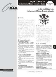
Protection).The current sensing circuit actually<br />
regulates the inductor valley current (see<br />
Figure 3). This means that if the current limit is<br />
set to 3A, the peak current through the<br />
inductor would be 3A plus the peak ripple<br />
current, and the average current through the<br />
inductor would be 3A plus 1/2 the<br />
peak-to-peak ripple current. The equations for<br />
setting the valley current and calculating the<br />
average current through the inductor are<br />
Figure 3. Valley Current Limiting<br />
The equation for the current limit threshold is as<br />
follows:<br />
= ×<br />
⎛<br />
−<br />
×⎜<br />
R ⎞<br />
⎟<br />
⎝ ⎠<br />
6 SEN<br />
ISEN<br />
10 10 A<br />
⎜R<br />
⎟<br />
DS(ON)<br />
The current limit looks at the “valley current”<br />
(I VALLEY ), which is average output current minus<br />
half the ripple current. The valley current is<br />
⎛I<br />
⎞<br />
= − ⎜ ⎟<br />
⎝ 2 ⎠<br />
RIPPLE<br />
IVALLEY<br />
IOUT<br />
A<br />
Where : I RIPPLE is I PEAK - I LIMIT .<br />
Therefore, the current limit resistor (R SEN ) can be<br />
calculated by output current and valley current as<br />
⎛ R<br />
DS(ON) ⎞<br />
RSEN = 1.4× IVALLEY ×⎜ Ohms<br />
-6 ⎟<br />
⎝10×<br />
10 ⎠<br />
Where :<br />
R SEN is resistance between Phase and ISEN pins.<br />
R DS(ON) is typically 26 m Ohm (Vgs=4.5V, I DS =5A).<br />
TITLE: SPECIFICATION OF <strong>HM03145</strong><br />
PAGE REV:A1<br />
PAGE 15 OF 30