Kit 67. DC SPEED CONTROLLER - Electronics123.net
Kit 67. DC SPEED CONTROLLER - Electronics123.net
Kit 67. DC SPEED CONTROLLER - Electronics123.net

You also want an ePaper? Increase the reach of your titles
YUMPU automatically turns print PDFs into web optimized ePapers that Google loves.
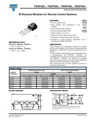
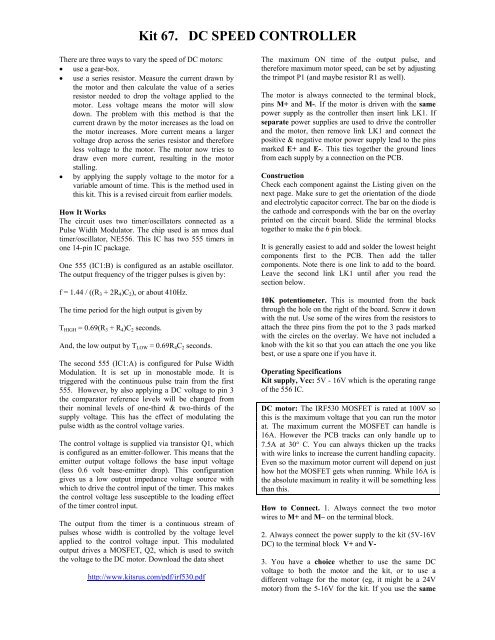
<strong>Kit</strong> <strong>67.</strong> <strong>DC</strong> <strong>SPEED</strong> <strong>CONTROLLER</strong><br />
There are three ways to vary the speed of <strong>DC</strong> motors:<br />
• use a gear-box.<br />
• use a series resistor. Measure the current drawn by<br />
the motor and then calculate the value of a series<br />
resistor needed to drop the voltage applied to the<br />
motor. Less voltage means the motor will slow<br />
down. The problem with this method is that the<br />
current drawn by the motor increases as the load on<br />
the motor increases. More current means a larger<br />
voltage drop across the series resistor and therefore<br />
less voltage to the motor. The motor now tries to<br />
draw even more current, resulting in the motor<br />
stalling.<br />
• by applying the supply voltage to the motor for a<br />
variable amount of time. This is the method used in<br />
this kit. This is a revised circuit from earlier models.<br />
How It Works<br />
The circuit uses two timer/oscillators connected as a<br />
Pulse Width Modulator. The chip used is an nmos dual<br />
timer/oscillator, NE556. This IC has two 555 timers in<br />
one 14-pin IC package.<br />
One 555 (IC1:B) is configured as an astable oscillator.<br />
The output frequency of the trigger pulses is given by:<br />
f = 1.44 / ((R 3 + 2R 4 )C 2 ), or about 410Hz.<br />
The time period for the high output is given by<br />
T HIGH = 0.69(R 3 + R 4 )C 2 seconds.<br />
And, the low output by T LOW = 0.69R 4 C 2 seconds.<br />
The second 555 (IC1:A) is configured for Pulse Width<br />
Modulation. It is set up in monostable mode. It is<br />
triggered with the continuous pulse train from the first<br />
555. However, by also applying a <strong>DC</strong> voltage to pin 3<br />
the comparator reference levels will be changed from<br />
their nominal levels of one-third & two-thirds of the<br />
supply voltage. This has the effect of modulating the<br />
pulse width as the control voltage varies.<br />
The control voltage is supplied via transistor Q1, which<br />
is configured as an emitter-follower. This means that the<br />
emitter output voltage follows the base input voltage<br />
(less 0.6 volt base-emitter drop). This configuration<br />
gives us a low output impedance voltage source with<br />
which to drive the control input of the timer. This makes<br />
the control voltage less susceptible to the loading effect<br />
of the timer control input.<br />
The output from the timer is a continuous stream of<br />
pulses whose width is controlled by the voltage level<br />
applied to the control voltage input. This modulated<br />
output drives a MOSFET, Q2, which is used to switch<br />
the voltage to the <strong>DC</strong> motor. Download the data sheet<br />
http://www.kitsrus.com/pdf/irf530.pdf<br />
The maximum ON time of the output pulse, and<br />
therefore maximum motor speed, can be set by adjusting<br />
the trimpot P1 (and maybe resistor R1 as well).<br />
The motor is always connected to the terminal block,<br />
pins M+ and M-. If the motor is driven with the same<br />
power supply as the controller then insert link LK1. If<br />
separate power supplies are used to drive the controller<br />
and the motor, then remove link LK1 and connect the<br />
positive & negative motor power supply lead to the pins<br />
marked E+ and E-. This ties together the ground lines<br />
from each supply by a connection on the PCB.<br />
Construction<br />
Check each component against the Listing given on the<br />
next page. Make sure to get the orientation of the diode<br />
and electrolytic capacitor correct. The bar on the diode is<br />
the cathode and corresponds with the bar on the overlay<br />
printed on the circuit board. Slide the terminal blocks<br />
together to make the 6 pin block.<br />
It is generally easiest to add and solder the lowest height<br />
components first to the PCB. Then add the taller<br />
components. Note there is one link to add to the board.<br />
Leave the second link LK1 until after you read the<br />
section below.<br />
10K potentiometer. This is mounted from the back<br />
through the hole on the right of the board. Screw it down<br />
with the nut. Use some of the wires from the resistors to<br />
attach the three pins from the pot to the 3 pads marked<br />
with the circles on the overlay. We have not included a<br />
knob with the kit so that you can attach the one you like<br />
best, or use a spare one if you have it.<br />
Operating Specifications<br />
<strong>Kit</strong> supply, Vcc: 5V - 16V which is the operating range<br />
of the 556 IC.<br />
<strong>DC</strong> motor: The IRF530 MOSFET is rated at 100V so<br />
this is the maximum voltage that you can run the motor<br />
at. The maximum current the MOSFET can handle is<br />
16A. However the PCB tracks can only handle up to<br />
7.5A at 30° C. You can always thicken up the tracks<br />
with wire links to increase the current handling capacity.<br />
Even so the maximum motor current will depend on just<br />
how hot the MOSFET gets when running. While 16A is<br />
the absolute maximum in reality it will be something less<br />
than this.<br />
How to Connect. 1. Always connect the two motor<br />
wires to M+ and M– on the terminal block.<br />
2. Always connect the power supply to the kit (5V-16V<br />
<strong>DC</strong>) to the terminal block V+ and V-<br />
3. You have a choice whether to use the same <strong>DC</strong><br />
voltage to both the motor and the kit, or to use a<br />
different voltage for the motor (eg, it might be a 24V<br />
motor) from the 5-16V for the kit. If you use the same
<strong>Kit</strong> <strong>67.</strong> <strong>DC</strong> <strong>SPEED</strong> <strong>CONTROLLER</strong><br />
voltage (5V – 16V) for both the kit and the motor then<br />
just add the link LK1 as marked on the PCB. Nothing<br />
goes into the E+ and E- positions on the terminal block.<br />
If running the motor from its own supply then do not<br />
insert the link LK1. Connect the motor external positive<br />
and negative supply to the terminal block E+ and E-.<br />
Note: We have found that a drop in the kit’s supply<br />
voltage causes the motor speed to drop. This normally<br />
happens when running the kit and motor from the same<br />
supply. In this case adjust trimpot P1 to get maximum<br />
speed. You may also need to vary resistor R1 as well.<br />
See the next page for how to adjust the trimpot for<br />
maximum speed.<br />
What To Do If It Does Not Work<br />
Check the orientation of the diode, the IC and the<br />
electrolytic capacitor. Did you make the 3 connections<br />
rom the potentiometer pins to the pads? Did you add the<br />
links as required, depending on whether or not you used<br />
the same power source for the motor as the controller?<br />
Check that all the resistors are in their correct positions.<br />
If you have a CRO or frequency meter check the output<br />
on pin 5 of the 556. Photos of this are on the next page<br />
COMPONENTS<br />
Resistors 5% 1/4W:<br />
10R brown black black R6 1<br />
470R yellow violet brown R2 1<br />
560R green blue brown R1 1<br />
10K brown black orange R5 1<br />
33K orange orange orange R3 1<br />
2K2 red red red R4 R7 2<br />
500R (501) Koa trimpot P1 1<br />
10K potentiometer, washer & nut 1<br />
1N4004 D1 2<br />
10uF/50V ecap C1 1<br />
100nF 104 monocap C2 to C7 6<br />
100uF/25V electrolytic C8 1<br />
Heatsink (HS110, HS313) 1<br />
Nmos LM/NE556 IC1 1<br />
IRF530 mosfet Q2 1<br />
BC547 Transistor Q1 1<br />
14 pin IC socket 1<br />
Nut & screw for heatsink<br />
1 set<br />
Two pole terminal block 3<br />
<strong>Kit</strong> 67V31 PCB 1<br />
Large Box P4210 & 4 screws 1
<strong>Kit</strong> <strong>67.</strong> <strong>DC</strong> <strong>SPEED</strong> <strong>CONTROLLER</strong><br />
Adjusting for Maximum Speed<br />
You do not need a CRO to adjust the trimpot for maximum<br />
speed but it helps if you can also see what is happening.<br />
Take the input from pin 5 of the LM/NE556. At the<br />
Slowest setting of the potentiometer this is what you<br />
should see.<br />
is turned on and this heating will also affect the trim<br />
position. The warming may be reduced by increasing R6<br />
to 100R but we have not experimented with this. So leave<br />
the kit turned on for a few minutes before trimming if you<br />
want to get the maximum trim position possible.<br />
If you turn the trimpot but get nowhere near the 99% pulse<br />
width position then short circuit R1 underneath the PCB<br />
and try again with the trimpot alone. There are variations<br />
between different brands of 556 and we have found some<br />
which required 650R – 800R but others which only needed<br />
400R to trim to maximum. Again we did not investigate<br />
this.<br />
(Sorry about the ripple!)<br />
See us at http://www.kitsrus.com<br />
(Documentation October 19, 2003. Changed from<br />
IRFZ44N to IRF530 MOSFET.)<br />
This is at about the mid-point of the Potentiometer as the<br />
pulse width and thus the motor speed is increased.<br />
At the Fastest position and using the trimpot P1 to trim for<br />
about 99% pulse width. If you over trim then the 556 will<br />
‘trip-over’ itself and the motor speed will drop. Here is<br />
what you see when you just over trim the trimpot from the<br />
above photo.<br />
If you have the motor attached then you will hear it drop in<br />
speed by about 10% - 20% when the 556 passes through<br />
this transition point.<br />
Note that you will have to retrim if the supply voltage<br />
changes. Note also that the 556 will heatup a little after it