Lexicon 480L | PDF - Freeverb3
Lexicon 480L | PDF - Freeverb3
Lexicon 480L | PDF - Freeverb3

Create successful ePaper yourself
Turn your PDF publications into a flip-book with our unique Google optimized e-Paper software.
Owner's Manual<br />
<strong>480L</strong><br />
Digital Effects System
<strong>Lexicon</strong> <strong>480L</strong> Owner's Manual<br />
Unpacking and Inspection<br />
After unpacking the <strong>480L</strong> and LARC, save all packing materials in case you ever need to ship the unit.<br />
Thoroughly inspect the <strong>480L</strong>, LARC, and packing materials for signs of damage in shipment. Report any<br />
damage to the carrier at once.<br />
Precautions<br />
The <strong>Lexicon</strong> <strong>480L</strong> is a rugged device with extensive electronic protection. However, reasonable precautions<br />
applicable to any piece of audio equipment should be observed.<br />
• Always use the correct AC line voltage. Refer to Chapter 1 of this manual for power requirements.<br />
• Do not install the <strong>480L</strong> in an unventilated rack, or directly above heat-producing equipment. Maximum<br />
ambient operating temperature is 35 o C (95 o F).<br />
• Never attach audio power amplifier outputs or other power sources directly to any of the <strong>480L</strong>'s connectors.<br />
• To prevent fire or shock hazard, do not expose the <strong>480L</strong> to rain or moisture.<br />
Notices<br />
In the interest of continued product development, <strong>Lexicon</strong> reserves the right to make improvements in this<br />
manual and the product it describes at any time and without notice or obligation.<br />
Copyright ©1993<br />
<strong>Lexicon</strong>, Inc.<br />
3 Oak Park<br />
Bedford, MA 01730 USA<br />
Tel: 781-280-0300<br />
Fax: 781-280-0490<br />
All Rights Reserved<br />
This publication is protected by copyright and all rights are reserved. No part of it may be reproduced or transmitted<br />
by any means or in any form, without prior consent in writing from <strong>Lexicon</strong>.<br />
Printed in the United States of America<br />
Warranty Notice<br />
The Nonvolatile Memory Cartridge supplied with this unit carries a 30-day limited warranty.<br />
<strong>Lexicon</strong> Part # 070-09360<br />
ii
Table of Contents<br />
Program Directory<br />
Introduction<br />
iv<br />
v<br />
1. Installing the <strong>480L</strong> 1-1<br />
About the Rear Panel 1-2<br />
About the Front Panel 1-3<br />
Behind the Front Panel 1-4<br />
About the LARC 1-5<br />
How to Mount the <strong>480L</strong> 1-6<br />
Power Requirements 1-6<br />
How to Interface the LARC 1-7<br />
Audio Connections 1-9<br />
How to Float the Analog Ground 1-9<br />
2. Basic Operation 2-1<br />
Glossary 2-2<br />
Operating Modes 2-3<br />
Checking Your System's Status 2-5<br />
Selecting a Configuration 2-5<br />
Using Two LARCs to Control<br />
a Single <strong>480L</strong> 2-7<br />
Controlling a 224XL from<br />
a <strong>480L</strong> and LARC 2-7<br />
Selecting Input Type 2-7<br />
How to Load Programs 2-8<br />
Level Calibration 2-9<br />
Setting Analog Output Levels 2-10<br />
Setting Analog Input Levels 2-11<br />
Levels in the Digital Domain 2-12<br />
Using Digital Signals 2-13<br />
How to Edit Parameters 2-14<br />
How to Use Registers 2-14<br />
Storing and Naming Programs 2-15<br />
Loading Registers 2-15<br />
Protecting Against Loss of<br />
Register Contents 2-15<br />
Moving Registers with the<br />
Register Transporter 2-16<br />
Clearing Register Contents 2-16<br />
MIDI SysEx Program Dumps 2-27<br />
3. Banks 1-4: the Reverb Programs 3-1<br />
About the Reverberation Algorithm 3-2<br />
About the Reverberation Parameters 3-4<br />
Bank 1 - Halls 3-8<br />
Bank 2 - Rooms 3-10<br />
Bank 3 - Wild Spaces 3-12<br />
Bank 4 - Plates 3-14<br />
4. Bank 5: the Effects Programs 4-1<br />
About the Effects Algorithm 4-2<br />
About the Effects Parameters 4-3<br />
Bank 5 - Effects 4-5<br />
5. Bank 6: the Twin Delays Programs 5-1<br />
About the Twin Delays Parameters 5-2<br />
Bank 6 - Twin Delays 5-4<br />
6. Bank 7: the Sampler Programs 6-1<br />
Introduction 6-2<br />
Bank 7 Samplers 6-3<br />
Bank 7 Samplers — SME Only 6-3<br />
How to Use the Samplers 6-4<br />
About the Sampling Parameters 6-9<br />
7. Bank 8: the Pitch and Doppler Programs 7-1<br />
About the Pitch Shift Parameters 7-2<br />
Bank 8 - Pitch Shift 7-4<br />
About the Doppler Parameters 7-5<br />
Bank 8 - Doppler 7-6<br />
8. Bank 9: the Mastering Programs 8-1<br />
About the Stereo Adjust Parameters 8-2<br />
PONS Adjust 8-5<br />
Digital Parametric EQ 8-7<br />
Panorama (Binaural) 8-10<br />
9. Bank 10: the Compressor Programs 9-1<br />
About the Compressor Parameters 9-2<br />
Bank 10 - Compressor/Expander 9-3<br />
10. Banks 11-12: the Random Halls and<br />
Spaces Programs 10-1<br />
About the Random Reverb Parameters 10-2<br />
Bank 11 - Random Hall 10-5<br />
Bank 12 - Random Rooms 10-7<br />
11. Banks 13-14: the Ambience Programs 11-1<br />
About the Ambience Parameters 11-2<br />
Bank 13 - Ambience 11-5<br />
Bank 14 - Post Ambience 11-7<br />
iii
<strong>Lexicon</strong> <strong>480L</strong> Owner's Manual<br />
12. Bank 15: the Prime Time III Programs 12-1<br />
About the Prime Time III Parameters 12-2<br />
Bank 12 - Prime Time III 12-4<br />
13. Bank 16: the Freq. Stuff Programs 13-1<br />
About the Frequency Dynamics<br />
Parameters 13-2<br />
Bank 16 - Frequency Dynamics 13-3<br />
About the Distression Parameters 13-4<br />
Bank 16 -Distression 13-6<br />
Appendix<br />
A. MIDI and the <strong>480L</strong><br />
B. Solving Problems<br />
C. Specifications<br />
D. Voltage Changeover<br />
and Optional Transformers<br />
E. Control Mode Reference<br />
14. Bank 17: the Test and Reference<br />
Programs 14-1<br />
About the Test & Reference Parameters 14-2<br />
Bank 17 - Test & Reference 14-3<br />
iv
Program Directory - Software Version 4.0<br />
Bank<br />
Program Name<br />
Bank 1 1.1 1.2 1.3 1.4 1.5 1.6 1.7 1.8 1.9 1.0<br />
480 Halls Large Large Medium Medium Small Small Large Small Jazz Auto<br />
Hall + Stage Hall + Stage Hall + Stage Church Church Hall Park<br />
Bank 2 2.1 2.2 2.3 2.4 2.5 2.6 2.7 2.8 2.9 2.0<br />
480 Rooms Music Large Medium Small Very Small Large Small Large Small Small<br />
Club Room Room Room Room Wood Rm Wood Rm Chamber Chamber & Bright<br />
Bank 3 3.1 3.2 3.3 3.4 3.5 3.6 3.7 3.8 3.9 3.0<br />
Wild Brick Buckram Big 10W-40 20W-50 Metallica Silica Inside Ricochet Varoom<br />
Spaces Wall Bottom Beads Out<br />
Bank 4 4.1 4.2 4.3 4.4 4.5<br />
Plates A Snare Small Thin Fat<br />
Plate Plate Plate Plate Plate<br />
Bank 5 5.1 5.2 5.3 5.4 5.5 5.6 5.7 5.8 5.9 5.0<br />
Effects Illusion Surfin' Vocal Doubler Back Rebound Git It Wet Sudden In the Tremolo<br />
Whispers Slap Stop Past L & R<br />
Bank 6 6.1 6.2 6.3 6.4 6.5 6.6 6.7 6.8 6.9 6.0<br />
Twin 4-Voice Double 4-Bounce Pitter X-Pan Delay Circles There Soft On<br />
Delays Double Delay Delay Patter Double Cave & Back Roller and On<br />
Bank 7 7.1 7.2 7.3 7.4 7.5 7.6 7.7 7.8 7.9 7.0<br />
Samplers* Stereo Mono Mono Dual Rate Mono Fwd Stereo Dual Rate Mono Fwd Stereo 10S Mono 20S<br />
3 Sec. 6 Sec. 3 Sec. Change & Rev 3S Drum Chg Drum Rev Drum Rate Chg Rate Chg<br />
Bank 8 8.1 8.2 8.3 8.4 8.5 8.6 8.7 8.8 8.9 8.0<br />
Pitch/ Pitch Pitch 1% Up Barber Half Stair XPres Indy Airport Airport<br />
Doppler Change Chorus 1% Down Pole Steps Case Subway Corner Land Tkof<br />
Bank 9 9.1 9.2 9.3 9.4 9.5 9.6 9.7 9.8 9.9 9.0<br />
Mastering The Stereo PONS M/S Invert Channel Stereo Stereo Mono Panorama<br />
In-Out Adjust Adjust Decode L-R Swap Param EQ 60Hz Ntch Param EQ<br />
Bank 10 10.1 10.2 10.3 10.4 10.5 10.6 10.7 10.8 10.9 10.0<br />
Compressor 2:1 6.24:1 18.28:1 Transfer Vox FM Nailed Noise 2-Slp- 2-Slp-<br />
Comp Comp Comp Easy Gate Mach A Mach B<br />
Bank 11 11.1 11.2 11.3 11.4 11.5 11.6 11.7 11.8 11.9 11.0<br />
Random Large Large R Medium R Medium R Small R Small R Large R Small R Jazz R Auto<br />
Hall R Hall + Stage Hall + Stage Hall + Stage Church Church Hall Park R<br />
Bank 12 12.1 12.2 12.3 12.4 12.5 12.6 12.7 12.8 12.9 12.0<br />
Random Music Large Medium Small Very Large Small Small Chorus Wet &<br />
Spaces Club R Room R Room R Room R Small R CHamber R Chamber R & Bright R Room Tacky<br />
Bank 13 13.1 13.2 13.3 13.4 13.5 13.6 13.7 13.8 13.9 13.0<br />
Ambience Very Large Large Medium Small Strong Heavy Ambient Announcer Closet Gated<br />
Ambience Ambience Ambience Ambience Ambience Ambience Hall Ambience<br />
Bank 14 14.1 14.2 14.3 14.4 14.5 14.6 14.7 14.8 14.9 14.0<br />
Post Car Living Bathroom Kitchen Kellars Small Warehouse Airhead Dial It Up Reverb<br />
Ambience Interior Room Ambience Cell Foley Tail<br />
Bank 15 15.1 15.2 15.3 15.4 15.5 15.6 15.7 15.8 15.9 15.0<br />
Prime Prime Slap Bounce Swirls Heavy Shake Wowza Wowza 2 Vocalz XFlange<br />
Time III Chorus Chorus Glide Detune It Up<br />
Bank 16 16.1 16.2 16.3 16.4 16.5 16.6 16.7 16.8 16.9 16.0<br />
Freq. Mix BG Drums AC Bass Carbon Saxophone Horn Softener Some<br />
Stuff Finish Vocals Guitars Thump Mic Blast Fuzz<br />
Bank 17 17.1 17.2 17.3 17.4 17.5 17.6 17.7 17.8 17.9 17.0<br />
Test & 100 Hz 500 Hz 500 Hz 1 kHz 1 kHz 10 kHz 30 Hz A-440 Pink Binaural<br />
Reference -12dB -17dB -12dB -17dB -12dB -12dB Slate Tuner Noise Simulator<br />
Program Directory - <strong>480L</strong> Classic Cart**<br />
Bank<br />
Program Name<br />
Bank 18 18.1 18.2 18.3 18.4 18.5 18.6 18.7 18.8 18.9 18.0<br />
Concert Concert Medium Small Gold Guitar Reggae Reflex Bright Dark Oliver's<br />
Hall Hall Hall Hall Hall Hall Hall Hall Hall Hall Hall<br />
Bank 19 19.1 19.2 19.3 19.4 19.5 19.6 19.7 19.8 19.9 19.0<br />
Rich Large Drum Vocal Vox Slap Guitar Short Horn Echo Silver<br />
Plate Plate Plate Plate Plate #2 Plate Plate Plate Plate Plate Plate<br />
Bank 20 20.1 20.2 20.3 20.4 20.5 20.6 20.7 20.8 20.9 20.0<br />
6-Voice Woo-Woo 6 Vc Korus 3-Voice 4-Voice Ekoz & Vocal Soft Hard Canyon Tuff<br />
Chorus Chorus Chorus Korus Chorus Echoes Echorus Korus Stuff<br />
Bank 21 21.1 21.2 21.3 21.4 21.5 21.6 21.7 21.8 21.9 21.0<br />
Multiband Closet Telephone Phartage Stadium Downstairs Bandsweep BassEchoes BandBounce Whispers On Stage<br />
Delays<br />
* Programs 7.9 and 7.0 require the Sampling Memory Expansion option. See your <strong>Lexicon</strong> dealer for details.<br />
* Programs in Banks 18-21 require the Classic Cart option. See your <strong>Lexicon</strong> dealer for details.<br />
v
Introduction<br />
Introduction<br />
You are about to begin using the most advanced digital<br />
effects system available—the <strong>Lexicon</strong> <strong>480L</strong>. The <strong>480L</strong><br />
is engineered for the all-digital production environment.<br />
Digital audio places strict requirements on every<br />
link in the signal chain, and the <strong>480L</strong> meets those<br />
requirements. With its unique 18 bit A/D and D/A<br />
converters, the <strong>480L</strong> produces a dynamic range of 98<br />
dB in the wet signal path. It is probably the only effects<br />
system available that doesn't raise the noise floor of a<br />
digital master. And the PCM 1610/1630 compatible<br />
digital I/O interface lets you add true stereo ambience<br />
and effects without leaving the digital domain.<br />
The <strong>480L</strong> doesn't just sound better—sheer computational<br />
power allows it to perform multiple audio tasks at<br />
the same time. And what tasks! In the current glut of<br />
throwaway digital devices with ever-cheaper versions<br />
of the same sounds, the <strong>480L</strong> offers remarkable new<br />
effects and reverb sounds.<br />
Its innovative reverb algorithms reflect a more accurate<br />
and natural model of the acoustic and psychoacoustic<br />
phenomena of reverb and ambience. Put the <strong>480L</strong> up<br />
against any other reverberator—you'll be amazed at<br />
the difference.<br />
Reverb is only part of the story. The <strong>480L</strong> produces<br />
astonishing effects you haven't even begun to dream<br />
about yet. And its sampling programs offer a variety of<br />
useful and unique features.<br />
The present software is powerful and comprehensive,<br />
a dramatic step forward in digital signal processing<br />
technology. Yet it hasn't explored the limit of the <strong>480L</strong>'s<br />
architecture, which is itself configured for future hardware<br />
expansion.<br />
If you are familiar with the venerable 224XL, you'll feel<br />
right at home with the LARC used to control the <strong>480L</strong>.<br />
However, there are enough differences in the way the<br />
two units operate that we strongly suggest that you<br />
read this manual as soon as possible. In it, you'll<br />
discover that the <strong>480L</strong>'s two high speed processors<br />
can operate in a variety of configurations. Samples can<br />
be processed with reverb or effects, all in the digital<br />
domain. Two <strong>480L</strong>s can be connected through their<br />
digital I/O ports for even wider creative horizons. The<br />
<strong>480L</strong> can even be connected to a 224XL and both units<br />
operated from a single LARC. And that's just the<br />
beginning of what you'll discover--when you read this<br />
manual!<br />
vii
1<br />
Installation and Audio Connections<br />
This chapter contains overviews of all of the<br />
<strong>480L</strong> controls, as well as information on<br />
mounting, installation and audio connection.
<strong>Lexicon</strong> <strong>480L</strong> Owner's Manual<br />
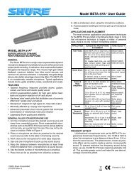
About the Rear Panel<br />
Main Inputs (L & R)<br />
The left and right Inputs<br />
accept 3-pin male XLR<br />
connectors. They are<br />
electronically balanced<br />
and (optionally) transformer<br />
isolated. Either pin<br />
2 or pin 3 can be used as<br />
high, but to maintain<br />
polarity when transferring<br />
data to the digital domain,<br />
pin 2 should be high. Pin 1<br />
and either pin 2 or pin 3 of<br />
each input must be<br />
grounded for unbalanced<br />
operation. Input impedance<br />
is 30 kilohms in<br />
parallel with 100 pF. Inputs<br />
accept input levels from +6<br />
to +24 dBm.<br />
Main Outputs (L & R)<br />
The left and right Main<br />
Outputs accept 3-pin<br />
female XLR connectors.<br />
They are electronically<br />
balanced and (optionally)<br />
transformer isolated. Either<br />
pin 2 or pin 3 can be used<br />
as high, but to maintain<br />
polarity when transferring<br />
data to the digital domain,<br />
pin 2 should be high. Pin 1<br />
and either pin 2 or pin 3 of<br />
each output must be<br />
grounded for unbalanced<br />
operation. Output impedance<br />
is 33 ohms, and<br />
levels up to +24 dBm are<br />
possible.<br />
Aux Ouputs (L & R)<br />
The left and right aux<br />
outputs are identical to the<br />
Main Outputs, except that<br />
they are used as secondary<br />
outputs when split or<br />
cascade modes are<br />
selected.<br />
Important. Reversing<br />
polarity on either input or<br />
output connectors can<br />
produce audible phase<br />
inversion effects. Improper<br />
phasing in the stereo path<br />
can create a weak or thin<br />
mix. Ensure that inputs<br />
and outputs are wired<br />
consistently.<br />
MIDI Connectors<br />
MIDI IN receives MIDI<br />
information from other<br />
MIDI-equipped devices.<br />
MIDI THRU retransmits<br />
MIDI information received<br />
at the MIDI In connector,<br />
without any change.<br />
MIDI OUT is used to<br />
transmit Automation data.<br />
<strong>Lexicon</strong> Digital<br />
Audio I/O Connector<br />
This DE9 connector<br />
provides PCM 1610-<br />
compatible digital I/O. It<br />
has 18-bit word length<br />
capability and can be<br />
slaved to a 48 kHz, 44.1<br />
kHz or 44.056 kHz<br />
external word clock.<br />
<strong>480L</strong> Rear Panel<br />
LARC 1 Connector<br />
This DE9 connector<br />
connects the mainframe to<br />
the <strong>Lexicon</strong> Alphanumeric<br />
Remote Control (LARC)<br />
via a flexible 50-ft cable<br />
(supplied)<br />
Automation Connector<br />
The Automation Connector<br />
is provided for future<br />
computer control and<br />
automation features.<br />
Important: Never connect<br />
a LARC to this connector.<br />
LARC 2 (Thru)<br />
Connector<br />
This DE9 connector allows<br />
connection of a second<br />
LARC. It also allows the<br />
<strong>480L</strong> to be connected to a<br />
224XL, with both units<br />
under control of a single<br />
LARC. A 10 ft cable is<br />
available from <strong>Lexicon</strong> for<br />
this application.<br />
Power Connector and<br />
Fuse Holder Cartridge<br />
The Power Connector is a<br />
standard 3-pin IEC power<br />
connector. The Fuse<br />
Holder Cartridge contains<br />
the AC mains fuse(s). The<br />
voltage changeover card is<br />
also contained in this<br />
compartment. Read<br />
Appendix D for voltage<br />
changeover information.<br />
1-2
Installation and Audio Connections<br />
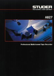
About the Front Panel<br />
Cartridge Slot<br />
The Cartride Slot accepts<br />
both ROM-based program<br />
cartridges, and Nonvolatile<br />
RAM cartridges for<br />
additional memory<br />
storage.<br />
The <strong>480L</strong> is shipped with<br />
one Nonvolatile Memory<br />
Cartridge, providing five<br />
banks of portable register<br />
storage. A write-protect<br />
switch prevents accidental<br />
erasure of contents.<br />
Front Panel Latch<br />
The front panel is hinged<br />
at the bottom; pull on the<br />
handle to open. Keep the<br />
front panel closed during<br />
normal operation to<br />
maintain dust filtration.<br />
Power Switch<br />
and Indicator<br />
The Power Switch turns<br />
the <strong>480L</strong> on and off; the<br />
indicator lights when the<br />
unit is on. A lithium battery<br />
retains the data memory<br />
when power is off or<br />
disconnected.<br />
<strong>480L</strong> Front Panel<br />
1-3
<strong>Lexicon</strong> <strong>480L</strong> Owner's Manual<br />
Behind the Front Panel<br />
Cooling Fan<br />
The cooling fan provides<br />
filtered forced air (the front<br />
panel vent is an air intake).<br />
The filter is removable and<br />
should be cleaned<br />
periodically with mild<br />
detergent and warm water.<br />
Card Retainer<br />
The card retainer ensures<br />
that the HSP and host<br />
processor cards remain<br />
firmly seated.<br />
Output Level Controls<br />
The output levels for the<br />
Main and Aux analog<br />
outputs may be adjusted<br />
independently over a<br />
range from +6 to +24 dBm<br />
(into 600 ohms) with these<br />
controls.<br />
Input Level Controls<br />
The input sensitivity for the<br />
left and right analog inputs<br />
may be adjusted independently<br />
to match inputs<br />
over a range of +8 to +28<br />
dBm with these controls.<br />
Nonvolatile<br />
Cartridge Cable<br />
This ribbon cable connects<br />
the cartridge slot to the<br />
host processor card via a<br />
locking connector on the<br />
host processor card.<br />
Caution: Use of excessive<br />
force when inserting<br />
cards into the <strong>480L</strong> can<br />
result in serious damage.<br />
Always make sure that<br />
the connectors are lined<br />
up properly before<br />
applying seating force.<br />
Diagnostic Indicators<br />
The four diagnostic<br />
indicators on the host<br />
processor card flash briefly<br />
upon powerup.<br />
Removable Modules<br />
The <strong>480L</strong> is completely<br />
modular. Every subassembly<br />
in the mainframe can<br />
be unplugged and<br />
removed for service or<br />
exchange. The standard<br />
complement for a <strong>480L</strong> is<br />
two HSP cards and a host<br />
processor card. The cards<br />
can be plugged into any<br />
slot in the mainframe, but<br />
for best noise performance,<br />
the HSP cards<br />
should be installed in the<br />
two top slots, and the host<br />
processor card directly<br />
beneath them. The empty<br />
bottom slot is provided for<br />
the optional SME card.<br />
Behind the Front Panel<br />
1-4
Installation and Audio Connections<br />
About the LARC<br />
Main Display<br />
Shows names and values<br />
for all selections.<br />
Headroom Indicator<br />
+12 dBm indicates analog<br />
or digital clipping. Proper<br />
input level is with +12 dB<br />
and ovld LEDs unlit.<br />
Numeric Keypad<br />
Press one of these keys to<br />
load a program selected<br />
with PROG or REG. Also<br />
used to select pages.<br />
Program-Select Key<br />
Press to enter Program<br />
mode. Press repeatedly to<br />
scroll through programs in<br />
a bank.<br />
Register-Select Key<br />
Press to enter Register<br />
mode. Press repeatedly to<br />
scroll through registers in a<br />
bank.<br />
Slider Display Line<br />
Shows abbreviated names<br />
of the parameters currently<br />
under the control of the<br />
sliders. Full name appears<br />
in the Main Display.<br />
Control Sliders<br />
Adjust parameter values.<br />
The LARC<br />
Slider Display Keys<br />
Show parameter name<br />
and value in main display.<br />
Press twice to engage<br />
vernier (fine) adjustment<br />
mode when available.<br />
Also used to trigger record<br />
and play events in Doppler<br />
and Sampler programs.<br />
Function Keys<br />
Bank scrolls through<br />
groups of programs or<br />
registers.<br />
VAR displays the running<br />
program or register name<br />
and the machine that the<br />
LARC is controlling.<br />
Pressing VAR again<br />
displays the current<br />
program and the page<br />
number of currently<br />
displayed parameters.<br />
STO stores edited<br />
parameter settings in<br />
registers (when REG is<br />
pressed at the same time.)<br />
CTRL toggles in and out of<br />
the control mode.<br />
MACH toggles between<br />
machines when Split or<br />
Cascade modes are<br />
selected, and also<br />
between the <strong>480L</strong> and<br />
224XL when a 224XL is<br />
connected to the <strong>480L</strong>.<br />
MUTE removes processed<br />
audio from outputs (only<br />
while it is pressed).<br />
2nd F is inactive.<br />
PAGE steps through<br />
pages of parameters.<br />
1-5
<strong>Lexicon</strong> <strong>480L</strong> Owner's Manual<br />
How to Mount the <strong>480L</strong><br />
The <strong>480L</strong> measures 19" wide x 5.25" high x 14.5" deep<br />
(483 x 133 x 368 mm). It can rest on any flat surface, or<br />
it can be mounted in a standard 19-in. (483 mm) relay<br />
rack. Do not install the <strong>480L</strong> directly above equipment<br />
which produces significant amounts of heat (such as<br />
power amplifiers); maximum ambient operating temperature<br />
is 40 o C (104 o F). Do not obstruct the ventilation<br />
exhaust ports on the right side panel, or the air intake<br />
on the front panel.<br />
If the <strong>480L</strong> is mounted in a rack or road case, we<br />
recommend that you provide support for the rear of the<br />
chassis during transport to prevent possible damage<br />
from severe mechanical shock.<br />
About the <strong>480L</strong>'s<br />
Power Requirements<br />
The <strong>480L</strong> is equipped with a three-pin IEC connector<br />
and detachable power cord, providing chassis grounding<br />
to the ac mains line. It can be operated at either 100/<br />
120 Vac or 220/240 Vac, depending on the fuses<br />
installed and the setting of the voltage changeover<br />
board.<br />
Note: Voltage changeover is<br />
described in Appendix D.<br />
The nominal operating voltage set at the <strong>Lexicon</strong><br />
factory is indicated by a small protruding pin on the<br />
power connector/fuse holder. Check this voltage setting<br />
before applying power to the unit! Power consumption<br />
is 70W typical, 180W maximum.<br />
Voltage selector set for 120 V.<br />
1-6
Installation and Audio Connections<br />
How to Interface the LARC<br />
The LARC 1 connector interfaces the mainframe to the<br />
<strong>Lexicon</strong> Alphanumeric Remote Control (LARC) via a<br />
flexible 50-ft cable (supplied). If your system is<br />
equipped with a single LARC, this is the connector you<br />
should use.<br />
The LARC 2 connector has two functions. It allows<br />
connection of a second LARC to the mainframe for<br />
applications where use of two LARCs is required. It can<br />
also be used to connect the <strong>480L</strong> to a 224XL with both<br />
units under the control of a single LARC. A 10' cable is<br />
available from <strong>Lexicon</strong> for this connection. (<strong>Lexicon</strong><br />
Part No. 680-04734) The pin assignments for the<br />
LARC connectors are shown to the right.<br />
Important: Never connect a LARC to the<br />
automation connector. Doing so may blow<br />
the internal automation connector fuse.<br />
Wiring diagram for the LARC mainframe connectors.<br />
Connections for <strong>480L</strong> with one LARC.<br />
1-7
<strong>Lexicon</strong> <strong>480L</strong> Owner's Manual<br />
Connections for <strong>480L</strong> with two LARCs.<br />
1-8
Installation and Audio Connections<br />
Analog Audio Connections<br />
See page 1-2 for details about audio interfacing<br />
(pinouts, impedance, etc.)<br />
The <strong>480L</strong> is designed to take advantage of the flexibility<br />
of a mixing console. The figure below shows a typical<br />
configuration. For maximum utility, use independent<br />
sends that can be assigned as either prefader or<br />
postfader. You can use the console's effects returns if<br />
they are pannable or assignable, but for greater creative<br />
control, you may wish to connect the <strong>480L</strong> outputs<br />
to regular input channels.<br />
We recommend experimentation to arrive at the best<br />
configuration for your own system. Actual connections<br />
should always be checked carefully for proper impedance,<br />
polarity, and levels.<br />
When using mono signal sources, either connect the<br />
left and right inputs in parallel, or use the mono split<br />
configuration (described in Chapter 2).<br />
Typical Audio Connections.<br />
Floating the Analog Ground<br />
In some applications it may be desirable to float the<br />
<strong>480L</strong>'s analog circuitry from the chassis ground. This<br />
can be accomplished by simply removing the blue<br />
jumper block located on the top side of the main circuit<br />
board near the two main input connectors. Store the<br />
jumper block on one of the posts in case you ever need<br />
to reinstall it.<br />
When the jumper block is removed, the analog signal<br />
grounds are floated from the chassis at DC, but are tied<br />
to the chassis for protection through a 1000 pF bypass<br />
capacitor and a 180 V metal oxide varistor.<br />
1-9
<strong>Lexicon</strong> <strong>480L</strong> Owner's Manual<br />
The <strong>480L</strong> and Digital Audio I/O<br />
In addition to its analog inputs and outputs, the <strong>480L</strong> is<br />
equipped with a PCM digital I/O connector. One application<br />
for digital I/O is processing material from a PCM<br />
1610 or compatible unit. The WET/DRY MIX control in<br />
the reverb and effects programs makes it possible for<br />
the <strong>480L</strong> to add signal processing to a stereo mix;<br />
without ever leaving the digital domain.<br />
Another application for digital I/O is to cascade two or<br />
more <strong>480L</strong>s together to create complex effects, again,<br />
without leaving the digital domain. In this application<br />
the first <strong>480L</strong> in the chain supplies word clock for the<br />
other units. Set the first unit for internal 48 kHz mode,<br />
and the second and subsequent units for external 48<br />
kHz mode.<br />
Drive levels and data format are compatible with the<br />
PCM 1610. Sync, preemphasis and flag bits are derived<br />
from the input bit stream. The <strong>480L</strong> may also be<br />
interfaced with the Sony 3324 digital multitrack recorder.<br />
The 3324 uses a balanced 1610 format, but this<br />
is easily accomodated by grounding the low side of<br />
each signal line at the <strong>480L</strong> interface connector.<br />
Input and Output Configuration<br />
The digital audio outputs can be used at the same time<br />
as the analog outputs, and they are always available at<br />
the Digital Audio I/O connector on the rear panel. The<br />
digital audio outputs receive the same material as the<br />
Main Outputs. The Aux Outputs are not available at the<br />
Digital I/O connector.<br />
The digital audio inputs cannot be used at the same<br />
time as the analog inputs. When the digital inputs are<br />
in use, the analog inputs are disabled.<br />
Important! Do not power up with external word<br />
clock present at the <strong>480L</strong>'s digital I/O port. Doing<br />
so may prevent the unit from finishing its<br />
power up sequence.<br />
If you encounter problems with distortion or loss of<br />
signal, the PLL circuitry may have become misaligned<br />
in shipment. See Appendix B, Solving Problems for<br />
details.<br />
Note: A digital audio I/O interface box which can<br />
greatly simplify interfacing the <strong>480L</strong> is available as<br />
an option. Contact your <strong>Lexicon</strong> Representative<br />
for details.<br />
Conversion to AES/EBU<br />
The <strong>480L</strong>'s 1610/1630 compatible signal can be translated<br />
to AES/EBU to allow interfacing with devices<br />
using this digital I/O format. To accomplish this, an<br />
external format converter such as <strong>Lexicon</strong>'s LFI-10 is<br />
required. The following figure details digital interconnection<br />
using a format converter.<br />
1-10
Installation and Audio Connections<br />
9 PIN MALE D-SUB CABLE CONNECTOR<br />
(REAR VIEW)<br />
CHASSIS MOUNT<br />
BNC JACKS<br />
EXTERNAL WORD CLOCK<br />
INPUT<br />
RIGHT CHANNEL<br />
INPUT<br />
LEFT CHANNEL<br />
INPUT<br />
5<br />
4<br />
3<br />
2<br />
1<br />
CHASSIS GND<br />
9<br />
8<br />
7<br />
6<br />
RIGHT CHANNEL<br />
OUTPUT<br />
LEFT CHANNEL<br />
OUTPUT<br />
WORD CLOCK<br />
OUTPUT<br />
TWISTED PAIR (6)<br />
OVERALL FOIL SHIELD<br />
USE BELDEN #S 9682, 9506, OR EQUIVALENT SHIELDED,<br />
LOW CAPACITANCE CABLE WITH 6 TWISTED PAIRS.<br />
Suggested interface for Digital I/O Connector.<br />
1-11
<strong>Lexicon</strong> <strong>480L</strong> Owner's Manual<br />
Typical 1610/1630 Connection<br />
Converting Digital Signals to AES/EBU Format.<br />
1-12
2<br />
Basic Operation<br />
This chapter describes the operations<br />
necessary to properly calibrate the<br />
<strong>480L</strong> in your facility.<br />
These include:<br />
Learning the operating modes<br />
Selecting machine configuration<br />
Switching machines from the LARC<br />
Selecting analog or digital inputs<br />
Loading programs<br />
Calibrating levels
<strong>Lexicon</strong> <strong>480L</strong> Owner's Manual<br />
Glossary<br />
• Mainframe Mainframe refers to a functional <strong>480L</strong><br />
operating with one or more machines.<br />
• Machine Each <strong>480L</strong> HSP board is addressed in the<br />
mainframe as an independent machine, or signal processing<br />
engine. In addition, the <strong>480L</strong> can recognize the<br />
<strong>Lexicon</strong> 224XL and address it as another machine.<br />
• Algorithm The <strong>480L</strong> contains several algorithms.<br />
An algorithm is a set of instructions that tells the <strong>480L</strong>'s<br />
microprocessors how to process the input signal. One<br />
algorithm produces effects, another reverberation, another<br />
sampling, etc. Each Machine in the <strong>480L</strong> can<br />
process an algorithm independently from the other<br />
machine.<br />
• Parameter Each algorithm has a set of parameters<br />
(controls) that uniquely characterize it. The settings of<br />
the parameters can be changed to create radically<br />
different sounds from a single algorithm.<br />
• Program A group of specific parameter settings<br />
permanently stored as separate programs in the <strong>480L</strong>.<br />
• Preset A group of specific parameter settings you<br />
create by editing presets and storing the new set of<br />
values.<br />
• Register Nonvolatile RAM memory locations in the<br />
mainframe, or in a removable nonvolatile memory<br />
cartridge, for storing presets.<br />
• Bank A bank is a collection of as many as ten<br />
programs or registers. Program banks contain a collection<br />
of similar programs derived from one or more<br />
algorithm. For example, the Halls bank contains reverberation<br />
programs that simulate large spaces, while<br />
the Mastering bank contains programs for level adjustment<br />
and digital equalization.<br />
• Pages The LARC can display and provide slider<br />
control for six parameters at a time. Because most<br />
algorithms have more than six parameters, they are<br />
grouped in blocks of six called pages. The PAGE<br />
button provides access to each group of parameters.<br />
• Control Mode The control mode contains several<br />
pages of utility parameters and functions which are not<br />
directly related to a single algorithm, such as sampling<br />
rate, register transporter, program name function, etc.<br />
The control mode is entered and exited by pressing the<br />
CTRL button on the LARC.<br />
• Configuration The <strong>480L</strong> machines can be configured<br />
to operate independently, or they can be combined<br />
to function as a single machine. The configuration<br />
is changed from the control mode. The <strong>480L</strong> is<br />
shipped in the single configuration.<br />
• dBFS A digital signal at full amplitude, or registering<br />
to the most significant bit.<br />
2-2
Basic Operation<br />
Operating Modes<br />
The <strong>480L</strong> is always in one of the following four operating<br />
modes:<br />
Machine Operation Mode<br />
Program Preview Mode<br />
Register Preview Mode<br />
Control Mode<br />
The <strong>480L</strong> always powers up in Machine Operation<br />
Mode.<br />
Each mode, and the paths for entering and exiting it are<br />
described below.<br />
Machine Operation Mode<br />
Press the PROG or the REG button, then press VAR.<br />
This mode allows you to:<br />
• View the machine currently being addressed by the<br />
LARC.<br />
• Display the program or preset currently running in<br />
the machine.<br />
• View and/or alter parameters.<br />
Program Preview Mode<br />
Press the PROG button.<br />
Press the BANK button to view program banks.<br />
Press the PROG button to view programs in the bank.<br />
This mode allows you to:<br />
• Select presets.<br />
Register Preview Mode<br />
Press the REG button.<br />
Press the BANK button to view register banks.<br />
Press the REG button to view programs in the bank.<br />
This mode allows you to:<br />
• Select, store, and recall programs from registers.<br />
• Address a cartridge in the mainframe cartridge slot.<br />
Control Mode<br />
Press the CTRL button. To exit, press CTRL, then<br />
press PROG, then press REG.<br />
This mode allows you to:<br />
• View system status.<br />
• Set machine and input configuration.<br />
• Alter input and set digital operation.<br />
• Address the register transporter.<br />
• Name programs.<br />
• Create Dynamic MIDI patches.<br />
• Transmit MIDI Program Change messages.<br />
• Enable MIDI SysEx Automation<br />
* Transmit MIDI Bulk Dumps<br />
2-3
<strong>Lexicon</strong> <strong>480L</strong> Owner's Manual<br />
Machine Operation Mode<br />
On power up, the <strong>480L</strong> restores the configuration, routing, and programs loaded before<br />
power was shut off. The LARC will display the last machine selected.<br />
Machine Under LARC Control<br />
Program Currently Running<br />
VAR<br />
MACHINE A<br />
LARGE HALL<br />
VAR<br />
LARGE HALL<br />
PAGE 1<br />
Program Currently Running<br />
Page of Parameters Under Control<br />
Program Preview Mode<br />
Register Preview Mode<br />
PROG<br />
REG<br />
BANK<br />
BANK<br />
MA B1 P1 MA B1 P1 LARC Display<br />
MA B1 R1 MA B1 R1 LARC Display<br />
Preview Program<br />
Banks<br />
Preview Programs<br />
Program 1<br />
Program 2<br />
Preview Register<br />
Banks<br />
Preview Registers<br />
Register 1<br />
Register 2<br />
1<br />
Halls<br />
Large Hall<br />
Large + Stage<br />
1<br />
REG Bank 1<br />
REG 1<br />
REG 2<br />
2<br />
3<br />
4<br />
5<br />
6<br />
7<br />
8<br />
9<br />
10<br />
Rooms<br />
Wild Spaces<br />
Plates<br />
Effects<br />
Twin Delays<br />
Sampling<br />
Pitch/Doppler<br />
Mastering<br />
Compression<br />
Press Numeric buttons 1-0 to<br />
load Program. Press button<br />
equal to flashing display to<br />
load Program currently<br />
displayed. Press the VAR<br />
button, or move a slider, or<br />
press a button under a slider<br />
to return to MACHINE RUN<br />
MODE<br />
2<br />
3<br />
4<br />
5<br />
6<br />
7<br />
8<br />
9<br />
10<br />
REG Bank 2<br />
REG Bank 3<br />
REG Bank 4<br />
REG Bank 5<br />
CART Bank 1<br />
CART Bank 2<br />
CART Bank 3<br />
CART Bank 4<br />
CART Bank 5<br />
Press Numeric buttons 1-0 to<br />
load Register. Press button<br />
equal to flashing display to<br />
load Register currently<br />
displayed. Press the VAR<br />
button, or move a slider, or<br />
press a button under a slider<br />
to return to MACHINE RUN<br />
MODE<br />
To Bank 21<br />
Control Mode<br />
Press CTRL to enter or exit CONTROL MODE<br />
VAR<br />
Indicates You are in Control Mode<br />
CONTROL MODE<br />
PAGE 1<br />
Page of Control Mode Parameters<br />
Page # Page Desc. Slider 1 Slider 2 Slider 3 Slider 4 Slider 5 Slider 6<br />
1<br />
Configuration<br />
Status<br />
Configuration<br />
Sampling Rate<br />
Clock<br />
Input<br />
2<br />
Copy Tools<br />
Copy<br />
From Source<br />
To Destination<br />
Power On<br />
Default<br />
REG Protect<br />
3<br />
Name Preset<br />
Select Char.<br />
Change Char.<br />
4<br />
5<br />
6<br />
MIDI Patching<br />
MIDI<br />
Configuration<br />
SysEx<br />
Functions<br />
Select Patch<br />
SysEx Auto<br />
SysEx Function<br />
Srce. Controller Parameter Dest.<br />
SysEc Channel<br />
Source to<br />
Transmit<br />
Pgm Change #<br />
SysEx<br />
Destination<br />
Reg Table<br />
Scale<br />
Pgm Change<br />
Mode<br />
Param. Value<br />
MIDI Channel<br />
2-4
Basic Operation<br />
Checking Your System's Status<br />
Press CTRL to enter Control Mode. Press PAGE, then<br />
press 1. Move slider one on page one of the control<br />
program for a quick display of the following information:<br />
• Configuration<br />
• Sampling rate selected<br />
• Clock source (internal or external)<br />
• Input source (analog or digital)<br />
• External Word Clock present/not present<br />
• Register protection status<br />
• Cartridge Status (formatted or unformatted,<br />
present or not present)<br />
<strong>480L</strong> Power-Up State<br />
Normally if power is lost, or turned off, and then<br />
restored, the <strong>480L</strong> will return to its last previous state.<br />
You can also configure the <strong>480L</strong> to automatically load<br />
pre-selected programs upon power up. To do this, go<br />
to Control Mode, Page two, slider 5. This slider, labeled<br />
DEF for default, is set at the factory to “off”. Advancing<br />
the slider will scroll through all of the <strong>480L</strong> programs<br />
and select one as the new default state. The upper<br />
display will indicate the machine you are addressing,<br />
followed by the Bank number, Program number and<br />
Program name. In order to select a default load for the<br />
second machine, press the MACH button and advance<br />
the slider to the desired program.<br />
Control configuration is always remembered regardless<br />
of power-up default setting.<br />
The Cascade Configuration<br />
The Cascade configuration feeds the output of one<br />
program (Machine A) directly into the input of the<br />
second program (Machine B). This allows you to process<br />
a stereo signal with two entirely different effects-<br />
-without ever leaving the digital domain. The Main<br />
outputs are connected to Machine B, and contain the<br />
processed signal from both Machine A and Machine B.<br />
The Aux outputs contain only the signal from Machine<br />
A.<br />
In the Cascade configuration, the MIX control found in<br />
most programs becomes very important, because it is<br />
the only method you have of controlling the mix between<br />
the two programs.<br />
Inputs<br />
L R<br />
Machine<br />
A<br />
Machine<br />
B<br />
L R<br />
Main Outputs<br />
L R<br />
Aux Outputs<br />
Selecting a Configuration<br />
System configuration, input type and system clocking<br />
are selected in Control Mode. To enter or exit Control<br />
Mode, press CTRL.<br />
Note: Pressing VAR will display the operating mode of<br />
the mainframe.<br />
Configurations are selected with Slider 2 on page 1 of<br />
the control mode. There are four internal configurations<br />
available:<br />
• Cascade<br />
• Stereo Split<br />
• Mono Split<br />
• Single<br />
Because the Configuration slider redefines the internal<br />
architecture of the <strong>480L</strong>, the display takes a bit longer<br />
to update after you move the slider than other parameters.<br />
Let's take a closer look at the four configurations.<br />
The Stereo Split Configuration<br />
The Stereo Split configuration also uses the <strong>480L</strong> as<br />
two independent signal processors. It differs from the<br />
Mono Split in that both inputs are sent to both programs;<br />
in other words, Machine A and Machine B<br />
receive the same stereo input signal. The Main outputs<br />
are used for Machine A, and the Aux outputs are used<br />
for Machine B.<br />
L<br />
Machine<br />
A<br />
L R<br />
Main Outputs<br />
Inputs<br />
R<br />
Machine<br />
B<br />
L R<br />
Aux Outputs<br />
2-5
<strong>Lexicon</strong> <strong>480L</strong> Owner's Manual<br />
The Mono Split Configuration<br />
The Mono Split configuration uses the <strong>480L</strong> as two<br />
independent signal processors. Each program has an<br />
independent mono input and an independent stereo<br />
output. The Left input always goes to the first program<br />
(Machine A), and the Right input always goes to the<br />
second program (Machine B). The Main Outputs produce<br />
stereo output from Machine A, and the Aux<br />
Outputs produce stereo output from Machine B.<br />
L<br />
Machine<br />
A<br />
Inputs<br />
R<br />
Machine<br />
B<br />
The Single Configuration<br />
A few programs (like Stereo Sampler) require all of the<br />
<strong>480L</strong>'s processing power, and cannot be run at the<br />
same time as other programs. The Single configuration<br />
is provided for these programs. In the Single configuration,<br />
the outputs of the program are available at both<br />
the Main and Aux Outputs.<br />
L<br />
Inputs<br />
R<br />
Machine<br />
A<br />
L R<br />
Main Outputs<br />
L R<br />
Aux Outputs<br />
L R<br />
Main Outputs<br />
L R<br />
Aux Outputs<br />
Selecting a Machine<br />
Once a configuration has been selected, press CTRL<br />
to exit Control Mode. Now, pressing MACH switches<br />
LARC control from one machine to the other.<br />
Press MACH<br />
HSP-1<br />
HSP-2<br />
MACHINE A<br />
MACHINE B<br />
Press MACH<br />
HSP-1<br />
HSP-2<br />
MACHINE A<br />
MACHINE B<br />
2-6
Basic Operation<br />
Using Two LARCs<br />
to Control a Single <strong>480L</strong><br />
If you frequently use your <strong>480L</strong> in the Split or<br />
Cascade modes, you may wish to consider purchasing<br />
a second LARC. Having two LARCs allows<br />
you to control two programs simultaneously, without<br />
switching back and forth with MACH. Two LARCs<br />
are also useful if the <strong>480L</strong> is to be shared between<br />
two different rooms.<br />
In addition to controlling two programs at once, the<br />
second LARC can be used to display two pages of<br />
parameters for a single program.<br />
The second LARC should be connected to the LARC 2<br />
(Thru) connector on the rear panel of the <strong>480L</strong>. Refer<br />
to Chapter 1 for details.<br />
Controlling a 224XL<br />
from a <strong>480L</strong> and LARC<br />
In facilities equipped with both a <strong>480L</strong> and a 224XL, it<br />
may be useful to control both systems from a single<br />
LARC. To do this, connect the LARC 2 (Thru) connector<br />
to the 224XL LARC connector, as shown in<br />
Chapter 1. Use the MACH key on the LARC to switch<br />
the LARC between the 224XL and the <strong>480L</strong>. If you are<br />
running two programs on the <strong>480L</strong> at the same time,<br />
there will be three choices to step through each time<br />
you press MACH.<br />
Selecting Input Type<br />
Slider 6 on Page 1 of Control Mode allows selection of<br />
either analog or digital input. Both analog and digital<br />
outputs are always active.<br />
Before selecting digital input, be sure that proper<br />
connections have been made to the <strong>480L</strong> Digital I/O.<br />
(See Chapter 1.)<br />
Use the Clock slider on Page 1 of Control Mode to<br />
select EXTERNAL CLOCK. Set digital clock and sampling<br />
rate to match your application according to the<br />
table below.<br />
Analog<br />
Digital<br />
Clock Internal Clock External<br />
Sampling Rate 44.1 or Sampling Rate to match Digital<br />
48kHz<br />
Input Rate<br />
Input Analog Input Digital<br />
To determine whether the <strong>480L</strong> is correctly receiving<br />
external word clock, move the Status slider (Slider 1,<br />
Page 1 of Control Mode) to display external word clock<br />
status.<br />
IMPORTANT<br />
DO NOT POWER UP THE <strong>480L</strong> WITH EXTERNAL<br />
WORD CLOCK PRESENT AT THE <strong>480L</strong>'S DIGI-<br />
TAL I/O PORT. DOING SO MAY PREVENT THE<br />
UNIT FROM COMPLETING ITS NORMAL POWER<br />
UP ROUTINE.<br />
Connecting a <strong>480L</strong> and a 224XL together simply allows<br />
you to control the 224XL as you always have--none of<br />
the <strong>480L</strong>'s new capabilities are added to it. For example,<br />
the 224XL cannot access the register mover or<br />
other <strong>480L</strong> control mode functions. Also, the 224XL<br />
cannot be accessed by the LARC while the <strong>480L</strong> is in<br />
the control mode. If you press MACH while in the<br />
control mode, the 224XL will not appear in the display.<br />
As soon as you exit the control mode, the 224XL can be<br />
selected.<br />
1<br />
2<br />
3<br />
4<br />
SHIELD<br />
1<br />
2<br />
3<br />
4<br />
5<br />
NC<br />
NC<br />
5<br />
6<br />
6<br />
7<br />
7<br />
8<br />
8<br />
9<br />
NC<br />
NC<br />
9<br />
224XL Mainframe Interconnect Cable Wiring<br />
2-7
<strong>Lexicon</strong> <strong>480L</strong> Owner's Manual<br />
How to Load Programs<br />
In order to complete system setup, you will have to load<br />
programs into the <strong>480L</strong> machines.<br />
Remember that programs are variations of algorithms<br />
with parameters that have been set at the factory.<br />
Prorams are stored in Banks, with a collection of as<br />
many as 10 similar programs stored in each bank.<br />
Select a Bank<br />
In order to select a program, you must first select the<br />
bank in which the program is stored. There are two<br />
ways to select banks:<br />
1. Press PROG, then press BANK. This puts you in<br />
Program Preview Mode. The bank number flashes to<br />
indicate banks are being previewed, and the display<br />
shows the current bank name and number.<br />
Press BANK repeatedly. The LARC will scroll through<br />
the banks and display their names.<br />
2. Press PROG, then press BANK, then press one of<br />
the numeric keys (two for double digit bank numbers)<br />
to navigate directly to a specific bank.<br />
Load a Program<br />
<strong>480L</strong> programs are loaded by pressing the numeric<br />
button that matches the flashing LARC display.<br />
Press PROG, and then press a numeric button (1-0).<br />
The LARC will flash the message "SETUP LOADED."<br />
You will find that you can navigate between programs<br />
very quickly with this method. For example, enter the<br />
following keystrokes:<br />
PROG BANK 1 PROG 1 = Large Hall<br />
PROG BANK 9 PROG 7 = Stereo Parametric EQ<br />
PROG BANK 7 PROG 4 = Dual Rate Chg Sampler<br />
PROG BANK 8 PROG 8 = Indy Corner<br />
PROG BANK 3 PROG 1 = Brick Wall<br />
Once a program is loaded, the <strong>480L</strong> will switch from<br />
Program Preview Mode to Machine Operation Mode.<br />
The new program name will be displayed, and the first<br />
page of variable parameters will appear on the LARC.<br />
Detailed information on program parameters is found<br />
in later chapters of this manual.<br />
Select a Program<br />
Once a bank has been selected, you can view the<br />
programs in that bank without loading them. To do this,<br />
press PROG. The bank display on the LARC will stop<br />
flashing and the program display will begin flashing.<br />
The current program name and number will be displayed.<br />
Press PROG repeatedly. The LARC will scroll through<br />
the programs in the selected bank.<br />
2-8
Basic Operation<br />
Level Calibration<br />
Analog Input and Output levels should be set with care<br />
to obtain the best possible performance from the <strong>480L</strong>.<br />
The diagram below illustrates the signal flow through<br />
the mainframe. In addition, several programs are available<br />
in Bank 17 Test & Reference to help you optimize<br />
the performance of your system.<br />
Set Test Configuration<br />
Use the Single Machine configuration:<br />
1. Press CTRL, press PAGE, then press 1.<br />
2. Move Slider 2 to select SINGLE.<br />
3. Press CTRL or PROG to exit Control Mode and<br />
enter Machine Operation Mode.<br />
IMPORTANT<br />
MUTE CONTROL ROOM MONITORS<br />
BEFORE PROCEEDING.<br />
Left Channel<br />
A/D Converter<br />
LEFT<br />
Analog Input<br />
Gain Stage<br />
RIGHT<br />
44.1 kHz<br />
48 kHz<br />
Internal Sampling Frequncy<br />
Right Channel<br />
A/D Converter<br />
INT.<br />
WORD CLOCK<br />
SDIF DIGITAL AUDIO<br />
EXT.<br />
Word Clock Switch<br />
LEFT CH. DATA<br />
RIGHT CH. DATA<br />
SDIF DIGITAL<br />
AUDIO INTERFACE<br />
WORD CLOCK<br />
LEFT CH. DATA<br />
RIGHT CH. DATA<br />
LEFT CH. ANALOG<br />
LEFT CH. DIGITAL<br />
RIGHT CH. ANALOG<br />
SIGNAL<br />
PROCESSING<br />
Wet<br />
Bus<br />
Data<br />
Left MAIN<br />
D/A Converter<br />
Right MAIN<br />
D/A Converter<br />
Left AUX<br />
D/A Converter<br />
LEFT MAIN<br />
RIGHT MAIN<br />
LEFT AUX<br />
RIGHT CH. DIGITAL<br />
Input Selector Switch<br />
Right AUX<br />
D/A Converter<br />
RIGHT AUX<br />
Analog Output Gain Stage<br />
Signal Flow through the <strong>480L</strong> Mainframe<br />
2-9
<strong>Lexicon</strong> <strong>480L</strong> Owner's Manual<br />
Setting Analog Output Levels<br />
The <strong>480L</strong> has digital oscillator programs to aid in<br />
setting system output levels.<br />
Set nominal output level to design center of receiving<br />
equipment as follows:<br />
2. A digitally-generated 1kHz should appear at all<br />
outputs (both analog and digital).<br />
Set the analog output level controls for both Main and<br />
Aux Out to register nominal operating level on the<br />
device receiving this signal.<br />
1. Load program 17.5 1kHz -12dB as follows:<br />
Press PROG<br />
Press BANK<br />
Press 1, then press 7<br />
Press PROG<br />
Press 5<br />
If additional headroom is desired, load program 17-4<br />
(1kHz -17dB).<br />
# Bits Dynamic Range<br />
in dB<br />
LARC Meters<br />
0VU or Design Center<br />
(Nominal Operating Level)<br />
1<br />
dBFS<br />
+12 dB<br />
2<br />
3<br />
4<br />
-6 dB<br />
-12 dB<br />
-18 dB<br />
+6 dB<br />
0 dB<br />
-6 dB<br />
HEADROOM<br />
+8 dBv (1.95 volts)<br />
+4 dBv (1.95 volts)<br />
-10 dBv (0.245 volts)<br />
5<br />
-24 dB<br />
-12 dB<br />
6<br />
-30 dB<br />
-18 dB<br />
7<br />
8<br />
-36 dB<br />
-42 dB<br />
-24 dB<br />
-12 dB headroom for Pop recordings<br />
9<br />
-48 dB<br />
10<br />
11<br />
-54 dB<br />
-60 dB<br />
-18 dB headroom for live recordings - Classical, Jazz<br />
12<br />
-66 dB<br />
13<br />
-72 dB<br />
14<br />
-84 dB<br />
15<br />
-90 dB<br />
16<br />
-96 dB<br />
17<br />
-102 dB<br />
18<br />
-108 dB<br />
Dynamic Range and Headroom Calibration<br />
2-10
Basic Operation<br />
Setting Analog Input Levels<br />
Once output levels have been calibrated as directed in<br />
the previous section, you can proceed to the input<br />
levels.<br />
Before proceeding, make sure that the Oscillator<br />
program is loaded. Severe feedback can occur if<br />
any other program is running.<br />
1. Connect Main outputs L&R to the main inputs L&R<br />
as shown below.<br />
2. Press the button below the ILVL slider. The LARC<br />
will display input level over a 90dB range from dBFS.<br />
3. Adjust analog input gain controls until the LARC<br />
LED display level reads 0dB.<br />
4. Move the WAVE slider until 2 is displayed.<br />
5. Press the button below ILEV to display input level.<br />
6. Fine trim analog input gain controls until 78.0dB is<br />
displayed for both left and right channels.<br />
Analog signals are calibrated for Unity Gain.<br />
L<br />
Main Outputs<br />
Audio<br />
Signal<br />
Signal<br />
Processor<br />
Input<br />
Signal<br />
Processor<br />
Outputs<br />
Aux Outputs<br />
R<br />
Digital Outputs<br />
Input Level Display<br />
Signal Flow of Oscillator Program — Single Configuration<br />
2-11
<strong>Lexicon</strong> <strong>480L</strong> Owner's Manual<br />
Levels in the Digital Domain<br />
Analog signals, by nature, have an infinite range of<br />
level. During conversion to digital, levels are quantized<br />
to absolute values, and expressed as a number of bits.<br />
The <strong>480L</strong> provides 18-bit resolution in both the analog<br />
and digital paths. In the digital domain, it is important to<br />
provide adequate headroom so that peak amplitude<br />
does not exceed dBFS. The difference between the<br />
headroom provided and the dither noise, or least<br />
significant bit, is the usable dynamic range of the<br />
system.<br />
As you can see in the figure below, the <strong>480L</strong> provides<br />
signal-to-noise and dynamic range that exceed many<br />
popular digital recording media.<br />
# Bits Dynamic Range<br />
in dB<br />
LARC Meters<br />
Use of Dynamic Range<br />
in an 18 bit system<br />
Use of Dynamic Range<br />
in a 16 bit system<br />
1<br />
2<br />
3<br />
4<br />
5<br />
6<br />
7<br />
8<br />
9<br />
10<br />
11<br />
12<br />
13<br />
14<br />
15<br />
16<br />
dBFS<br />
-6 dB<br />
-12 dB<br />
-18 dB<br />
-24 dB<br />
-30 dB<br />
-36 dB<br />
-42 dB<br />
-48 dB<br />
-54 dB<br />
-60 dB<br />
-66 dB<br />
-72 dB<br />
-84 dB<br />
-90 dB<br />
-96 dB<br />
+12 dB<br />
+6 dB<br />
0 dB<br />
-6 dB<br />
-12 dB<br />
-18 dB<br />
-24 dB<br />
HEADROOM<br />
84 dB Dynamic Range<br />
18 dB Headroom<br />
102 dB Theoretical Dynamic Range<br />
17 -102 dB<br />
18 -108 dB<br />
18 Bit Dither Noise<br />
HEADROOM<br />
78 dB Dynamic Range<br />
12 dB Headroom<br />
90 dB Theoretical Dynamic Range<br />
16 Bit Dither Noise<br />
Dynamic Range of Digital Signal Path<br />
2-12
Basic Operation<br />
Using Digital Signals<br />
Several programs in the <strong>480L</strong> allow you to increase the<br />
level of the digital signal beyond dBFS. For example, if<br />
the Parametric EQ program is loaded, and a low shelf<br />
filter is boosted +6dB at 250Hz, the potential headroom<br />
to dBFS is reduced accordingly. (See the figure below.)<br />
If the audio material fed through this program contains<br />
a large amount of energy in the region of the shelf<br />
boost, an overload in the digital domain may occur.<br />
When this happens, the last segments of the LARC<br />
display will illuminate.<br />
Many programs, such as Parametric EQ, have a master<br />
level control which can offset the overall gain to<br />
prevent this situation. If you consistently encounter<br />
such situations, contact <strong>Lexicon</strong> Customer Service.<br />
dBFS<br />
+ =<br />
20 Hz 200 Hz 2 kHz 20 kHz <strong>480L</strong> Parametric EQ 20 Hz 200 Hz 2 kHz 20 kHz<br />
Low Shelf +6dB at 250 Hz<br />
2-13
<strong>Lexicon</strong> <strong>480L</strong> Owner's Manual<br />
How to Edit Parameters<br />
The sounds of the programs supplied with the <strong>480L</strong><br />
cover an astounding range of possibilities, but sooner<br />
or later you will want to alter the sounds of the programs<br />
to more perfectly fit your requirements. Each program<br />
in the <strong>480L</strong> contains a set of parameters that can be<br />
edited to create a sound uniquely your own.<br />
Just Move the LARC's Sliders<br />
After loading a program, you can edit its parameters by<br />
moving the LARC's sliders. Most parameters can be<br />
edited in real time to alter an effect. However, a few<br />
parameters (like SIZE) have such a radical effect on<br />
the <strong>480L</strong>'s algorithms that the effects signal is muted<br />
briefly when they are edited.<br />
To indicate the parameter that a slider controls, an<br />
abbreviated code appears in the display window above<br />
each active slider. You can display a more descriptive<br />
title and the current value for each parameter by<br />
pressing the keys directly below each slider. Moving a<br />
slider also displays this information.<br />
In many cases, pressing a display key twice will engage<br />
a vernier (fine) adjustment mode that allows very<br />
precise adjustment. The display blinks to indicate that<br />
the vernier mode is active.<br />
How to Use Registers<br />
The ability to edit parameters would be of little value if<br />
there were no way for the <strong>480L</strong> to store the edits. Not<br />
to worry--the <strong>480L</strong> has 100 registers available to store<br />
edited versions of the programs. Registers are organized<br />
into banks, selected, and loaded exactly like the<br />
programs. You can also edit parameters in a register,<br />
and store the results in the same register or another<br />
register.<br />
There are five banks of ten registers in internal memory.<br />
Another five banks of ten registers can be stored<br />
in a nonvolatile memory cartridge. One cartridge is<br />
supplied with the unit, and additional cartridges may be<br />
purchased.<br />
IMPORTANT<br />
Cartridges are equipped with a write protect<br />
switch. When the switch is ON, it prevents the<br />
<strong>480L</strong> from writing to the cartridge, regardless<br />
of the register protection selected in the <strong>480L</strong>.<br />
Cartridges may be shipped with the write protect<br />
switch in the ON position.<br />
Change Pages to Access More<br />
Parameters<br />
Because the programs in the <strong>480L</strong> have more than the<br />
six parameters which the LARC can display at one<br />
time, parameters are grouped in several pages. Each<br />
page contains up to six parameters. You can use either<br />
of two methods to move between pages:<br />
1. Press PAGE repeatedly to step through the pages<br />
sequentially.<br />
2. Press PAGE and then a numeric-select key to go<br />
directly to the page you want.<br />
IMPORTANT<br />
When a new program is loaded or another page<br />
is selected, each slider is deactivated (i.e., the<br />
display does not change) until the slider is<br />
moved through its preset value.<br />
When changes have been made on a page, and you<br />
move to a new page, the previous edits remain intact.<br />
However, when a new program is loaded, the edits you<br />
made disappear forever (unless you stored the edits in<br />
a register).<br />
Write Protect<br />
On Off<br />
exicon<br />
Write Protect<br />
Switch<br />
2-14
Basic Operation<br />
Storing and Naming Prorams<br />
After you have made the changes you want to a<br />
program's parameters, you can store the changed<br />
version in a register:<br />
When you store a register, the edited program still has<br />
the same name as the original program. To avoid<br />
confusion, you can assign names to registers. To<br />
rename a register:<br />
1. Press CTRL to enter the control mode.<br />
2. Press PAGE, then press 3 to go to page three.<br />
3. Press the key under the slider marked SEL to<br />
activate the select function. The current name of the<br />
program appears in the lower display.<br />
4. Move the SEL slider. Note that different characters<br />
within the name are selected by a pair of brackets<br />
< > as you move the slider. Select the first character in<br />
the program name.<br />
5. Use the CHG slider to change the character. Note<br />
that a blank space is available at the bottom of the<br />
slider's range, as are several symbols.<br />
6. Repeat steps 4 and 5 until all the characters in the<br />
new name have been entered successfully.<br />
To store your newly-named program in a register:<br />
1. Press REG once to exit Control mode, and enter<br />
the register mode.<br />
2. Press BANK repeatedly to locate the bank you<br />
wish to store the register in. Banks 1 through 5 are<br />
internal registers, and banks 6 through 10 are stored in<br />
the nonvolatile memory cartridge.<br />
Note: If you have difficulty using a cartridge, it<br />
may not have been formatted. Also, cartridges<br />
formatted with earlier versions of software<br />
may not work with later versions until they are<br />
reformatted. See Appendix B for instructions<br />
on how to format the cartridge.<br />
Loading Registers<br />
Registers are organized into banks, selected and<br />
loaded in exactly the same manner as programs.<br />
However, you press REG to switch from program to<br />
register mode, and press REG instead of PROG when<br />
selecting, storing, and loading registers.<br />
Protecting Against<br />
Loss of Register Contents<br />
Setting up a large number of registers to meet your<br />
personal requirements can represent a considerable<br />
investment of time and effort. To reduce the possibility<br />
of accidental loss of the contents of these registers, the<br />
<strong>480L</strong> has a memory protection feature. When memory<br />
protection is on, the <strong>480L</strong> does not allow anyone to<br />
erase the contents of a register by overwriting it.<br />
However, unused registers can be written to.<br />
The <strong>480L</strong> has four protection levels:<br />
• PROTECT INT AND CART<br />
• PROTECT CART<br />
• PROTECT INT<br />
• PROTECT OFF<br />
PROTECT INT protects just the internal registers, but<br />
allows registers stored in the cartridge to be overwritten.<br />
PROTECT CART protects the cartridge, but<br />
allows internal registers to be overwritten. PROTECT<br />
INT AND CART protects both internal and cartridge<br />
registers. To activate memory protection:<br />
1. Press CTRL to enter the control mode.<br />
2. Press PAGE, 2 to go to page 2.<br />
3. Move slider six to select one of the four protection<br />
modes.<br />
4. Press CTRL to exit the control mode.<br />
Once activated, memory protection remains in effect<br />
until it is turned off again.<br />
3. Press REG repeatedly to locate an "Unused"<br />
register, or a register you don't mind erasing.<br />
4. With the register number that you want to use<br />
flashing on the display, hold down STO and press<br />
REG. The LARC display flashes<br />
SETUP STORED<br />
This lets you know that the program was stored correctly.<br />
2-15
<strong>Lexicon</strong> <strong>480L</strong> Owner's Manual<br />
Protecting Your Registers<br />
Against Another Kind of Loss<br />
After creating a collection of registers, some users may<br />
not wish to let others access their "trademark" sounds.<br />
If this concerns you, copy any internal registers that<br />
you create to a nonvolatile memory cartridge at the end<br />
of each session (using the register transporter in the<br />
control mode). Then use the register clear function<br />
(also found in the control mode) to remove the registers<br />
from internal memory. Take the cartridge with you<br />
when you leave the facility.<br />
Use of the register transporter and register clear functions<br />
are described below.<br />
Moving Registers Around<br />
with the Register Transporter<br />
The register transporter has four functions:<br />
• Copy single registers from one location to<br />
another<br />
• Move single registers from one location to<br />
another<br />
• Copy all internal registers to a cartridge<br />
• Copy all cartridge registers to internal memory<br />
When registers are copied, the original register source<br />
remains intact. When registers are moved, the original<br />
register source is cleared.<br />
IMPORTANT<br />
The register protect function found on page<br />
two of the control mode must be set to OFF if<br />
any moves or copies are to overwrite existing<br />
registers.<br />
To copy entire register contents between internal and<br />
cartridge memory:<br />
1. Press CTRL to enter the control mode.<br />
2. Press PAGE, 2 to go to page 2.<br />
3. Use slider one to select CPY CART TO INTER-<br />
NAL or CPY INTERNAL TO CART.<br />
4. Hold down STO and press REG to complete the<br />
copy.<br />
To move or copy single registers:<br />
1. Press CTRL to enter the control mode.<br />
2. Press PAGE, 2 to go to page 2.<br />
3. Use slider one to select MOVE or COPY.<br />
4. Use slider two to select the source.<br />
5. Use slider three to select the destination.<br />
6. Hold down STO and press REG to complete the<br />
copy or move.<br />
Clearing Register Contents<br />
Page two of the control mode has a CLEAR control that<br />
allows complete removal of register contents. CLEAR<br />
has three functions:<br />
• Clear a single register<br />
• Clear all internal registers<br />
• Clear all cartridge registers<br />
To clear a single register:<br />
1. Press CTRL to enter the control mode.<br />
2. Press PAGE, 2 to go to page two.<br />
3. Use slider one to select CLR SETUP.<br />
4. Use slider two to select the register that you wish<br />
to clear.<br />
5. Hold down STO and press REG to clear the<br />
selected register.<br />
To clear all cartridge or internal registers:<br />
1. Press CTRL to enter the control mode.<br />
2. Press PAGE, 2 to go to page two.<br />
3. Use slider two to select CLR ALL INT or CLR ALL<br />
CART.<br />
4. Hold down STO and press REG to clear the<br />
selected registers.<br />
Note: When either CLR ALL INT or CLR ALL<br />
CART are selected, the BANK and REG sliders<br />
are inactive.<br />
Note: When either of these two modes are<br />
selected, the SRC and DST sliders are inactive.<br />
2-16
Basic Operation<br />
MIDI SysEx Program Dumps<br />
Programs and presets can also be transmitted and<br />
received as MIDI SysEx data. Parameters that enable<br />
MIDI SysEx dumps are found on Page 6 in Control<br />
mode.<br />
SysEx Bulk Dump<br />
Slider 1 (SFN) selects a SysEx Bulk Dump function.<br />
Slider 2 (SRC) is dependent on the SFN setting, but, in<br />
general, it selects the source of the dump function<br />
when required. The following SFN settings are available:<br />
SETUP<br />
BANK<br />
ACTIVE<br />
ALL INT<br />
ALL CART<br />
MIDI MAP<br />
CONTROLS<br />
Individual Program or Preset Dumps<br />
The SETUP function will bulk dump a single program or<br />
preset. When in this mode the SRCslider selects the<br />
particular setup to dump. Moving the slider scrolls<br />
through all of the available programs and registers<br />
containing presets. After selecting a particular program<br />
or preset, push and hold the STO button. While holding<br />
STO, press REG. This will enable a dump of the<br />
selected program or preset from either SFN or SRC<br />
mode. The format of the setup bulk dump message is<br />
described in Appendix A MIDI and the <strong>480L</strong>.<br />
Dumping Banks<br />
The BANK function will bulk dump a whole bank of<br />
programs or presets. The SRC slider selects from<br />
among the program banks and all ten register banks<br />
(five internal and five external cartridge banks).The<br />
bank selected is then dumped by pushing STO and<br />
REG as in individual setup dumps. A bank is dumped<br />
as a contiguous group of ten programs or registers.<br />
Each program or register within the bank, is dumped as<br />
a separate SysEx message, using the same format as<br />
that for individual dumps. When the dump is activated,<br />
the LARC displays "DUMPING BANK." When the<br />
dump is complete, the LARC displays "BANK<br />
DUMPED."<br />
Dump Active Algorithm(s)<br />
The ACTIVE function dumps one or both of the active<br />
algorithms and their current parameter values instead<br />
of a register or preset. When the machine is in SINGLE<br />
configuration, only Machine A can be dumped, otherwise<br />
Machine A, Machine B, or both A and B can be<br />
selected with the SRC slider. As with all dumps described<br />
earlier, the dump is activated by the combination<br />
STO/REG button push. The format of the dump<br />
message is described in Appendix A MIDI and the<br />
<strong>480L</strong>.<br />
If the SRC slider is set to “MACHINE A+B” each<br />
machine will be sent as an individual SysEx message,<br />
just as though you selected “MACHINE A” and did a<br />
dump, then repeated the process for “MACHINE B”.<br />
When the dump operation is activated, the LARC<br />
displays "DUMPING ACT A" for Machine A only. The<br />
LARC displays "DUMPING ACT B" for Machine B only,<br />
or "DUMPING A+B" when both machines are selected.<br />
When each Machine is dumped, the LARC displays<br />
"ACT A(or B) DUMPED"<br />
Dump All Internal Registers<br />
To dump all internal registers to MIDI set SFN to “ALL<br />
INT”. In this mode the SRC slider is not required.The<br />
“ALL INT” dumps register banks from 1-5 to MIDI. Each<br />
register is dumped as a single SysEx message described<br />
in Appendix A MIDI and the <strong>480L</strong>..The presets<br />
are dumped in order of appearance in the register<br />
banks. As other functions, the dump action is initiated<br />
by holding STO and pressing REG. Once the dump of<br />
all internal registers is started, the LARC displays<br />
"DUMPING INT." When the dump is completed, the<br />
LARC displays "INT DUMPED."<br />
Dump All Cartridge Registers<br />
The dump all cartridge function is very similar to the<br />
Dump All Internal Registers function with Banks 6-0<br />
dumped rather than Banks 1-5. The LARC displays<br />
"DUMPING CART." When the dump is completed the<br />
LARC displays "CART DUMPED."<br />
2-17
<strong>Lexicon</strong> <strong>480L</strong> Owner's Manual<br />
Dump MIDI Program Table Map<br />
The <strong>480L</strong> has a program map that translates MIDI<br />
program change numbers to <strong>480L</strong> program or register<br />
numbers. There is a map for each Machine, A and B.<br />
As in the ACTIVE function, the SRC slider selects from<br />
three possibilities: Machine A, Machine B or Machine<br />
A +B.The MIDI MAP bulk dump function dumps the<br />
selected map(s) to the MIDI port. Dump action is<br />
started holding STO and pressing REG. The format for<br />
the MIDI map is documented in Appendix A MIDI and<br />
the <strong>480L</strong>. The LARC displays "DUMPING MAP A,"<br />
"DUMPING MAP B," or "DUMPING MAPS," depending<br />
on selection. When the dump is complete, the<br />
LARC displays "MAP (A, B or A+B) DUMPED."<br />
Dump Controls<br />
The SRC slider is not needed for this function. After<br />
moving the slider to CONTROLS and pushing STO/<br />
REG, a copy of the current parameters available in<br />
Control Mode are dumped. The following is a list of the<br />
controls dumped:<br />
• Configuration<br />
• Sample Rate<br />
• Clock Source<br />
• Input Source<br />
• Audio Mute<br />
• Reg Protect<br />
• Sysex Channel Device ID<br />
• Sysex Automation Mode<br />
• Sysex Receive Mode<br />
When dumping is activated, the LARC displays<br />
"DUMPING CTRLS." When complete, the LARC displays<br />
"CTRLS DUMPED."<br />
SysEx Restore Bulk Dump<br />
Slider 3, on Page 6, labeled RCV, selects the destination<br />
of MIDI bulk dumps loaded back into the <strong>480L</strong>. The<br />
simplest destination is the default, “ORIGINAL SRC”.<br />
This function restores presets to wherever they originated.<br />
An internal register is written back over the<br />
current register at that location. See the message<br />
format documentation to discover the source for each<br />
register. Programs or presets can also be restored to<br />
the active Machines. If the configuration is SINGLE,<br />
then only Machine A can be restored. Otherwise, any<br />
program or register loaded to the <strong>480L</strong> can be sent to<br />
either Machine A or Machine B with “ACTIVE A” or<br />
“ACTIVE B” selected under RCV.<br />
The bank modes are more complicated. If any of the<br />
“INT BNK” or “CART BNK” selections are made, any<br />
preset will be sent to the first register in the selected<br />
bank. The <strong>480L</strong> will attempt to place subsequent presets<br />
sequentially into the next registers in the bank<br />
selected. This should only be used to restore dumped<br />
banks.<br />
Restore Individual Presets<br />
Loading a previously dumped preset will replace the<br />
preset at the location with the MIDI SysEx version<br />
when the RCV slider is set to “ORIGINAL SRC”. Other<br />
settings in the RCV slider cause other actions to occur:<br />
“ACTIVE A” or “ACTIVE B” sends the preset to the<br />
appropriate machine as a running program<br />
Selecting one of the banks, loads the preset into the<br />
first register of the bank, or into a subsequent register<br />
if it was dumped in sequence with a previously restored<br />
preset.<br />
Any attempt to restore a program to its original<br />
source will be ignored. The error message "PROG<br />
RCVD" will be displayed.<br />
When presets are successfully restored, the LARC will<br />
display an approrpiate message for each type:<br />
"ACT A LOADED" or "ACT B LOADED" indicates that<br />
an active algorithm was restored.<br />
If a preset was received as an Internal Register, "1<br />
REG LOADED" is displayed.<br />
If a preset is received as a Cartridge register, "C REG<br />
LOADED" is displayed.<br />
Restore Banks<br />
2-18
Basic Operation<br />
A dumped register bank will be restored to its original<br />
location if “ORIGINAL SRC” is selected. If the bank was<br />
a program bank, restoring to original source will not<br />
change anything in the <strong>480L</strong>.<br />
If the RCV slider is set to an active Machine, all of the<br />
programs or presets in the bank will load one at a time<br />
into the selected Machine until the last one, which will<br />
be left running when the process is complete.<br />
When completed, the LARC will display "ACT A<br />
LOADED," or ACT B LOADED," depending on the<br />
Machine selected.<br />
If a new bank is selected, it will be written to the new<br />
location. The LARC will display either "1 REG<br />
LOADED," or "C REG LOADED," depending on its<br />
destination.<br />
Restore Active Machines<br />
Any dump of an active Machine will restore as that<br />
active machine if the RCV slider is set to “ORIGINAL<br />
SRC.” If the RCV slider is set to “MACHINE A” or<br />
“MACHINE B,” the load will be to that machine, despite<br />
any destination stored in the message itself.<br />
When RCV is set to restore to a particular bank, then<br />
the bulk dump data will replace the first register in the<br />
bank unless the data for machine A and B are sent<br />
sequentially, in which case the data will replace register<br />
1 and 2 in the selected bank.<br />
The LARC displays either "1 REG LOADED," or "C<br />
REG LOADED," depending on its destination.<br />
Restore All Internal Registers<br />
If all of the dumped internal registers are restored with<br />
the RCV slider set to “ORIGINAL SRC,” each register<br />
will be overwritten. Any other setting of RCV is not<br />
recommended.<br />
Selection of destination is not an option when restoring<br />
MIDI program table map. The data is restored to the<br />
active Machine where it originated.<br />
Restore Controls<br />
Selection of destination is not an option when restoring<br />
MIDI Controls. The data is restored to the control<br />
parameters of the active Machine. See Dump Controls<br />
for a list of the controls dumped and restored.<br />
MIDI Request Data<br />
The request data function is a MIDI SysEx message<br />
that triggers an output of the requested bulk dump on<br />
the MIDI port. The format for the request function is<br />
defined in Appendix A MIDI and the <strong>480L</strong>.. The possible<br />
requests are as follows:<br />
• Request All Stored Presets(Internal and<br />
Cartridge Registers)<br />
• Request Individual Program<br />
• Request Individual Preset<br />
• Request Controls<br />
• Request Active Machine A<br />
• Request Active Machine B<br />
• Request MIDI Program Map for Machine A<br />
• Request MIDI Program Map for Machine B<br />
The data will be sent after the <strong>480L</strong> receives and<br />
decodes the message. If automation transmit mode is<br />
on, the data sent will also contain automation messages.<br />
Internally, the <strong>480L</strong> decodes the request message<br />
and uses the normal event passing mechanism to<br />
transmit the response. This activates the automation<br />
mode if enabled. To get just the data requested, turn off<br />
the automation transmit mode on the control page, or<br />
by transmitting a SysEx message before sending the<br />
request.<br />
The LARC will display "1 REG LOADED."<br />
Restore All Cartridge Registers<br />
Restoring all cart registers works identically to the<br />
restore all internal registers except that in “ORIGINAL<br />
SRC” mode the data is sent to banks 6-0 instead of to<br />
1-5. The LARC displays "C REG LOADED." All other<br />
operations are the same.<br />
Restore MIDI Program Table Map<br />
2-19
3<br />
Banks 1-4: the Reverb Programs<br />
In this chapter we'll discuss the original<br />
Reverberation and Plate programs<br />
created for the <strong>480L</strong>.<br />
Two different algorithms are used to create these<br />
programs. The primary difference between the two is<br />
the density of the reverberation. The algorithm with<br />
greater density is used primarily for Room and Plate<br />
programs. To discover which algorithm is used by a<br />
particular program, go to page three to see how many<br />
pre-echo voices are available — the dense algorithm<br />
has only two voices.<br />
Both algorithms have fixed, or "static" reverberation<br />
characteristics. A new algorithm, with random motion<br />
characteristics is described in Banks11 -12: Random<br />
Halls and Rooms. The Random Hall algorithm provides<br />
a smoother reverberant characteristic, and is<br />
better suited for material which requires large space<br />
emulation, or longer reverb time.
<strong>Lexicon</strong> <strong>480L</strong> Owner's Manual<br />
Before we jump into detailed descriptions of the<br />
programs and parameters, let's take a look at the<br />
philosophy behind the reverberation algorithm's radical<br />
new structure.<br />
About the<br />
Reverberation Algorithm<br />
The <strong>480L</strong> incorporates the results of a great deal of<br />
research into acoustics and reverberation. It produces<br />
four general classes of sounds: ambience, room simulations,<br />
plates, and gated sounds.<br />
In Search of Ambience<br />
Ambience is the use of reverberation or reflected<br />
sound energy to give recorded music a sense of being<br />
performed in a real acoustic location. Ideally, ambience<br />
gives warmth, spaciousness and depth to a<br />
performance without coloring the direct sound at all.<br />
Recent research into ambience has shown that this<br />
phenomenon depends most critically on the shape of<br />
the initial reverberation build-up and decay. Ambience<br />
is perceived and has benefit while the music is running<br />
(which is most of the time). But once the reverberation<br />
has decayed 15 dB it is no longer audible in the<br />
presence of the direct sound. So the time it takes for the<br />
sound to build up and decay 15 dB determines the<br />
perceived reverb time, regardless of what the decay<br />
time to -60 dB is. Some very good halls for recording<br />
have a rather uneven initial build-up and decay, giving<br />
a much longer effective reverb time than their -60 dB<br />
reverb time might suggest.<br />
It has become common practice to use predelay in an<br />
attempt to emulate the sound of these halls. Adding<br />
delay to the reverb sends definitely increases the<br />
effective audible reverb time and the apparent size of<br />
the hall, but the result sounds unnatural.<br />
If we make echograms of real halls, we find that there<br />
is usually a gradual buildup of energy between the<br />
arrival of the direct sound and the time at which the<br />
reverberation reaches maximum loudness. The sharp<br />
attack of added predelay in most reverberation devices<br />
sounds entirely different.<br />
In the <strong>480L</strong>, the SIZE, SPREAD and SHAPE controls<br />
allow adjustment of the buildup and decay of the initial<br />
part of the reverberation envelope. SHAPE controls<br />
the shape of the envelope, while SPREAD and SIZE<br />
set the time over which this shape is active.<br />
In the hall and room programs, SIZE acts as a master<br />
control for the apparent size of the space being created<br />
by the <strong>480L</strong>. Both SPREAD and RT MID varylinearly<br />
with the setting of SIZE. Thus maximum reverb time<br />
and spread require high settings of SIZE. To find an<br />
appropriate reverb sound, start with a preset with a<br />
similar sound to what you want to end up with. Simply<br />
varying SIZE is often sufficient to arrive at the exact<br />
sound you are seeking.<br />
Once a size has been selected, SPREAD and SHAPE<br />
are used to adjust the shape and duration of the initial<br />
reverb envelope, which together provide the major<br />
sonic impression of room size.<br />
When SHAPE is at minimum, the reverberation envelope<br />
builds up very quickly to a maximum amplitude,<br />
and then dies away quickly at a smooth rate. This<br />
envelope is characteristic of small reverberation chambers<br />
and reverberation plates. There are few (if any)<br />
size cues in this envelope, so it is ineffective in creating<br />
ambience. With this SHAPE setting, SPREAD has no<br />
effect. The density is set by the size control, and the<br />
rate of decay is set by RTMID. This reverberation<br />
envelope is typical of many of the popular digital<br />
reverberators of the last few years.<br />
As SHAPE is raised to 32 (about 1/8th of the way up)<br />
the initial sharp attack of the reverberation is reduced,<br />
and reverberation builds more slowly. The envelope<br />
then sustains briefly before it begins to die away at the<br />
rate set by RTMID. SPREAD has little or no effect on<br />
this shape.<br />
When SHAPE is at 64 (1/4 of the way up) buildup is<br />
even slower and the sustain is longer. Now SPREAD<br />
affects the length of both the buildup and the sustain.<br />
As a rough estimate, the sustain will be approximately<br />
the time value indicated by the SPREAD display (in<br />
milliseconds).<br />
As SHAPE is raised further, the buildup and sustain<br />
remain similar, but now a secondary sustain appears in<br />
the envelope, at a lower level than the first. This<br />
secondary plateau simulates a very diffused reflection<br />
off the back wall of a hall, and is effective in creating a<br />
sense of size and space. This reflection becomes<br />
stronger and stronger, reaching an optimal loudness at<br />
a SHAPE value of about 128 (1/2 way up).<br />
The highest SHAPE settings are typically used for<br />
effects. Near the top of the scale the back wall reflection<br />
3-2
Banks 1-4: the Reverb Programs<br />
becomes stronger than the earlier part of the envelope,<br />
resulting in a inverse sound.<br />
Note that none of these shape effects are audible<br />
unless RTMID is set short enough. Generally, RTMID<br />
should be set to a value of about 1.2 seconds for small<br />
rooms, and up to 2.4 seconds or so for halls. SIZE<br />
should also be set to a value appropriate to the desired<br />
hall size (note, however, that small sizes color the<br />
reverberation).15 meters makes a very small room,<br />
and 38 meters is useful for a large hall.<br />
Used with care SHAPE and SPREAD allow the <strong>480L</strong> to<br />
produce superior ambience—a sound which is spacious<br />
and has great depth—without the long RT60 of a<br />
church.<br />
Creating a Realistic Ambient Sound<br />
When you set out to create an ambient sound, the first<br />
and most important decision is how big a space you<br />
want. The best way to start is to listen to several presets<br />
and choose the one which sounds closest to what you<br />
have in mind. If necessary, use SIZE to make a slightly<br />
larger or smaller sound, as needed.<br />
Next use RTMID to fine-tune the amount of time the<br />
reverberation takes to die away at the end of musical<br />
phrases. Actual halls vary a great deal in their actual RT<br />
MID values. The setting of the BASS MULTIPLY is also<br />
critical in matching the sound of an existing hall. An<br />
ideal concert hall would have a BASS MULTIPLY<br />
setting of 1.2. It is rare when actual physical spaces<br />
exceed 1.5. Many (if not most) good recording environments<br />
have values of BASS MULTIPLY of 1.0 or less,<br />
and a value of 0.8 should be tried when attempting to<br />
match an existing hall.<br />
There are two additional controls to deal with. SHAPE<br />
and SPREAD adjust the effective reverb time when the<br />
music is running. Higher values of SHAPE and<br />
SPREAD produce a longer effective reverb time.<br />
Longer effective reverb times give greater spaciousness<br />
to the sound.<br />
The Early Reflection Myth<br />
The importance of early reflections in reverberation<br />
has become accepted as indisputable fact. We call it a<br />
myth. Much of the myth of early reflections is a result of<br />
attempts to emulate the sound of discrete reflections<br />
from the floor, stage area, and ceiling of a real hall. This<br />
sounds reasonable in theory, but it has been our<br />
experience that the resulting preechoes are much<br />
different from the early reflections present in real halls,<br />
and recorded music is often better off without them.<br />
The reason for the difference is not difficult to discover.<br />
Early reflections in artificial reverberation are usually<br />
discrete--simply a delayed version of the original<br />
sound. Transients such as clicks or drums are clearly<br />
heard as discrete reflections, resulting in a coarse,<br />
grainy sound. But the reflective surfaces of real halls<br />
are complicated in shape, and the reflections they<br />
produce are smoothed or diffused. Their time and<br />
frequency responses are altered, making them much<br />
more interesting. In a very good hall, discrete reflections<br />
are hard to identify as such.<br />
Another major disadvantage of discrete early reflections<br />
is that the same reflection pattern is applied to<br />
every instrument which is fed into the reverberation<br />
unit, and each instrument has its timbre altered in<br />
exactly the same way. In a real hall, every instrument<br />
has a different set of early reflections, and each instrument<br />
will have its timbre altered in a different way.<br />
Some engineers find any type of early reflection undesireable.<br />
In classical music, many recordings are now<br />
made with the orchestra in the middle of the hall, with<br />
the specific intention of avoiding early reflections. Too<br />
much early reflected energy makes the sound muddy,<br />
and does not add to richness or spaciousness. This is<br />
in part because reflections and reverberation also exist<br />
in the playback room.<br />
The <strong>480L</strong> reverberation algorithm still offers the option<br />
of adding early reflections (preechoes) but we have<br />
made them diffused clusters of preechoes. The density<br />
of the cluster is set by the DIFFUSION control. We<br />
recommend that these preechoes be used with caution,<br />
unless you are trying to match the sound of the<br />
reverberation to a particular location where such reflections<br />
are strong.<br />
When creating new reverberation sounds of your own,<br />
don't forget that an Effects program can be put in series<br />
with the reverberation (using the Cascade configuration<br />
described in Chapter 2). The result can be<br />
extremely interesting. Also, try using the Effects program<br />
to give high frequencies a different envelope from<br />
low frequencies.<br />
3-3
<strong>Lexicon</strong> <strong>480L</strong> Owner's Manual<br />
Page One<br />
RTM<br />
Mid Reverb Time<br />
SHP<br />
Shape<br />
SPR<br />
Spread<br />
SIZ<br />
Size<br />
HFC<br />
High Freq Cutoff<br />
PDL<br />
Predelay<br />
Page Two<br />
BAS<br />
Bass Multiply<br />
XOV<br />
Crossover<br />
RTC<br />
RT Hi Freq. Cutoff<br />
DIF<br />
Diffusion<br />
DCO<br />
Decay Optimization<br />
MIX<br />
Wet/Dry Mix<br />
Page Three<br />
[<br />
Echo Level 1 L>L<br />
PRE-<br />
Echo Level 2 R>R<br />
ECHO<br />
Echo Level 3 R>L<br />
-LEV<br />
Echo Level 4 L>R<br />
ELS-<br />
Echo Level 5 L>L<br />
]<br />
Echo Level 6 R>R<br />
Page Four<br />
[<br />
Echo Delay 1<br />
PRE-<br />
Echo Delay 2<br />
ECHO<br />
Echo Delay 3<br />
-DEL<br />
Echo Delay 4<br />
AY5<br />
Echo Delay 5<br />
]<br />
Echo Delay 6<br />
About the Reverberation Parameters<br />
Page One<br />
RTM (Mid-Frequency Reverb Time)<br />
RTM sets the reverb time for mid-frequency signals<br />
when the signal stops. Because low-frequency reverb<br />
time (BASS MULT) is a multiplier of RTM, RTM acts as<br />
a master control for the stopped reverb time. When<br />
DECAY OPT is set to Reverb mode, the actual value<br />
set for RTM varies with the setting of SIZE. SIZE should<br />
be adjusted before RTM. This interaction is deactivated<br />
when DECAY OPT is set to EFFECTS mode.<br />
SHAPE<br />
SHAPE and SPREAD work together to control the<br />
overall ambience of the reverberation created by the<br />
<strong>480L</strong>. SHAPE determines the contour of the reverberation<br />
envelope. With SHAPE all the way down,<br />
reverberation builds explosively, and decays quickly.<br />
Note: SPREAD only functions when<br />
SHAPE is set higher than eight.<br />
As SHAPE is advanced, reverberation builds up more<br />
slowly and sustains for the time set by SPREAD. With<br />
SHAPE in the middle, the buildup and sustain of the<br />
reverberation envelope emulates a large concert hall<br />
(assuming that SPREAD is at least halfway up, and<br />
that SIZE is suitably large—30 meters or larger.)<br />
SPREAD<br />
SPREAD works together with SHAPE to control the<br />
contour of the overall ambience of the sound created<br />
by the <strong>480L</strong>. SPREAD controls the duration of the initial<br />
contour of the reverberation envelope (SHAPE controls<br />
the envelope). Low SPREAD settings result in a<br />
rapid onset of reverberation at the beginning of the<br />
envelope, with little or no sustain. Higher settings<br />
spread out both the buildup and sustain.<br />
SPREAD and SHAPE control the rate at which reverberation<br />
builds up, and how the reverberation sustains<br />
as it begins to decay. When DECAY OPT is in Reverb<br />
mode, SPREAD is linked to SIZE, and the actual value<br />
for SPREAD depends on the selected SIZE.<br />
SIZE<br />
SIZE sets the rate of buildup of diffusion after the initial<br />
period (which is controlled by DIFFUSION). It also acts<br />
as a master control for RT MID and SPREAD. For this<br />
reason, the SIZE control can be used to vary a reverb<br />
sound from very large to very small. Generally, you<br />
should set the SIZE control to approximate the size of<br />
the acoustic space you are trying to create. The size in<br />
meters is roughly equal to the longest dimension of the<br />
space. Moving SIZE while a signal is present momentarily<br />
mutes the reverb signal.<br />
3-4
Banks 1-4: the Reverb Programs<br />
0 dB<br />
-30 dB<br />
Time<br />
The apparent size of the space created is actually a<br />
combination of the settings of the SIZE, SHAPE, and<br />
SPREAD controls. Small acoustic spaces are characterized<br />
by a rapid buildup of diffusion. However, both<br />
small and large spaces frequently have an uneven<br />
buildup of initial reverberation. This uneven buildup is<br />
what is controlled by the SPREAD and SHAPE controls.<br />
SHAPE Set All the Way Down.<br />
0 dB<br />
-30 dB<br />
Time<br />
SHAPE at 64 - 1/4 of the Way Up.<br />
0 dB<br />
-30 dB<br />
Time<br />
SHAPE at 128 - 1/2 of the Way Up.<br />
0 dB<br />
HF CUTOFF<br />
HF CUTOFF sets the frequency above which a 6 dB/<br />
octave low-pass filter attenuates the processed signal.<br />
It attenuates both preechoes and reverberant sound.<br />
High frequencies are often rolled off with this parameter,<br />
resulting in more natural sounding reverberation.<br />
PREDELAY<br />
PREDELAY sets the amount of time which elapses<br />
between input of signal and the onset of reverberation.<br />
Under natural conditions, the amount of predelay depends<br />
on the size and construction of the acoustic<br />
space and the relative position of the sound source and<br />
the listener(s). PREDELAY attempts to duplicate this<br />
phenomenon and is used to create a sense of distance<br />
and volume within an acoustic space. Relatively long<br />
PREDELAY settings place the reverberant field behind<br />
rather than on top of the input material. Extremely long<br />
PREDELAY settings produce unnatural sounds that<br />
often prove interesting.<br />
A sense of continuity between source and reverb is<br />
maintained up to around 40 ms of predelay, after which<br />
the sound begins to separate into distinct patterns;<br />
however, large values of PREDELAY can effectively<br />
give the impression of large size if early reflections are<br />
used to fill in the spaces between input and the delayed<br />
reverberation.<br />
Much of the effect of PREDELAY can be better<br />
achieved by using medium values of SHAPE, and<br />
setting the desired apparent predelay with SPREAD.<br />
Setting these parameters should be done by ear, since<br />
the values don't relate directly to ms.<br />
Note: Very high values of PREDELAY limit the<br />
amount of SPREAD available. The display does not<br />
reflect this, however.<br />
-30 dB<br />
Time<br />
SHAPE at 255 - All the Way Up.<br />
Short RT MID Setting.<br />
3-5
<strong>Lexicon</strong> <strong>480L</strong> Owner's Manual<br />
Page Two<br />
BASS MULTIPLY<br />
BASS MULTIPLY sets the reverb time for low-frequency<br />
signals, as a multiplier of the RT MID parameter.<br />
For example, if BASS MULTIPLY is set to 2X, and<br />
RT MID is set to two seconds, the low frequency reverb<br />
time will be four seconds. For a natural-sounding hall<br />
ambience, we recommend values of 1.5X or less.<br />
CROSSOVER<br />
CROSSOVER sets the frequency at which the transition<br />
from LF RT to RT MID takes place. CROSSOVER<br />
should be set at least two octaves higher than the low<br />
frequency you want to boost. For example, to boost a<br />
signal at 100 Hz, set the CROSSOVER to 400 Hz (This<br />
setting works well for classical music). CROSSOVER<br />
works best around 500 for boosting low frequencies,<br />
and around 1.5 kHz for cutting low frequencies.<br />
RT HF CUT<br />
RT HF CUT sets the frequency above which sounds<br />
decay at a progressively faster rate. It filters all the<br />
sound except the preechoes. When set relatively low,<br />
it gives a darker tone to the reverberation, simulating<br />
the effect of air absorption in a real hall. This also helps<br />
keep the ambience generated by the program from<br />
muddying the direct sound.<br />
DIFFUSION<br />
DIFFUSION controls the degree to which initial echo<br />
density increases over time. High settings of DIFFU-<br />
SION result in high initial buildup of echo density, and<br />
low settings cause low initial buildup. After the initial<br />
period (in which echo buildup is controlled by DIFFU-<br />
SION) density continues to change at a rate determined<br />
by SIZE. To enhance percussion, use high<br />
settings of diffusion. For clearer and more natural<br />
vocals, mixes, and piano music, use low or moderate<br />
settings of diffusion. The plate presets and some of the<br />
room presets use an algorithm with higher inherent<br />
diffusion. If high diffusion is desired, start with one of<br />
these presets. They are easily identifiable because<br />
they have only two preechoes.<br />
DECAY OPT (Decay Optimization)<br />
DECAY OPT alters program characteristics in response<br />
to changes in input level, to make reverberation<br />
decay sound more natural. DECAY OPT should normally<br />
be set to REVERB 7.<br />
To make it easy to create "wild spaces" DECAY OPT<br />
has a second mode--EFFECTS. In the EFFECTS<br />
mode, the numbers 0 - 9 have the same effect as they<br />
do in the REVERB mode. However, in the EFFECTS<br />
mode the SPREAD control is not linked to the SIZE<br />
control, making it possible to use high values of<br />
SPREAD with low values of SIZE. These settings can<br />
result in some interesting, but unnatural sounds.<br />
Note: On certain types of program material (such as<br />
soft low-frequency tones from a synthesizer) side<br />
effects may be audible during level changes. If these<br />
are heard, set DECAY OPT to REVERB 0 or EF-<br />
FECTS 0.<br />
WET/DRY MIX<br />
WET/DRY MIX controls the ratio of direct vs. effect<br />
signal in the output from a program. When the <strong>480L</strong> is<br />
patched into a console, this control should almost<br />
always be set to 100% wet. When an instrument is<br />
plugged directly into a <strong>480L</strong>, or when the Cascade<br />
configuration is in use, a setting between 45 and 60%<br />
is a good starting point for experimentation with this<br />
parameter.<br />
WET/DRY MIX is a sine/cosine fade. Practically<br />
speaking, this means that MIX can be adjusted over its<br />
range with little or no change in output level. When you<br />
control mix at the console, adding effect to the dry<br />
signal increases overall level.<br />
3-6
Banks 1-4: the Reverb Programs<br />
Page Three<br />
PREECHO LEVEL<br />
Preechoes can best be understood by visualizing a<br />
stage where the early reflections are the sounds emanating<br />
from the rear and side stage walls directly after<br />
the sound from the stage. Usually the rear stage wall<br />
reflection is earlier and louder than those from the two<br />
side walls. The preechoes are actually clusters of<br />
echoes, with the density of the cluster set by DIFFU-<br />
SION.<br />
The preecho reflection parameters change the perceived<br />
locations of reflecting surfaces surrounding the<br />
source. PREECHO LEVEL adjusts the loudness of the<br />
reflection.<br />
Note: Some of the presets use an algorithm with<br />
six preechoes, and others only have two. If you<br />
need more than two when creating a sound, be<br />
sure to start with a preset that has six.<br />
Page Four<br />
PREECHO DELAY TIME<br />
For each of the PREECHO LEVEL parameters, there<br />
is a corresponding PREECHO DELAY TIME parameter.<br />
PREECHO DELAY TIME sets the delay time in ms<br />
for one of the preechoes. PREECHO DELAY TIME is<br />
not affected by PREDELAY, so preechoes can be<br />
placed to occur before the reverberation starts.<br />
3-7
<strong>Lexicon</strong> <strong>480L</strong> Owner's Manual<br />
Programs — Bank 1: Halls<br />
1 Large Hall<br />
RTM SHP SPR SIZ HFC PDL<br />
2.19 s 126 179 37 m 2.862 24 ms<br />
BAS XOV RTC DIF DCO MIX<br />
1.2 x 752 Hz 4.186 99 R 7 All Fx<br />
Preecho Levels<br />
Off Off Off Off Off Off<br />
Preecho Delays<br />
0 ms 0 ms 0 ms 0 ms 0 ms 0 ms<br />
2 Large+Stage<br />
RTM SHP SPR SIZ HFC PDL<br />
2.19 s 126 179 37 m 2.862 24 ms<br />
BAS XOV RTC DIF DCO MIX<br />
1.2 x 752 Hz 4.186 99 R 7 All Fx<br />
Preecho Levels<br />
-12 dB -10 dB -8 dB -8 dB -9 dB -9 dB<br />
Preecho Delays<br />
16 ms 22 ms 64 ms 56 ms 112 ms 102ms<br />
3 Medium Hall<br />
RTM SHP SPR SIZ HFC PDL<br />
1.74 s 126 128 25 m 4.395 24 ms<br />
BAS XOV RTC DIF DCO MIX<br />
1.2 x 752 Hz 3.982 99 R 7 All Fx<br />
Preecho Levels<br />
Off Off Off Off Off Off<br />
Preecho Delays<br />
0 ms 0 ms 0 ms 0 ms 0 ms 0 ms<br />
4 Medium+Stage<br />
RTM SHP SPR SIZ HFC PDL<br />
1.74 s 126 128 25 m 4.395 24 ms<br />
BAS XOV RTC DIF DCO MIX<br />
1.2 x 752 Hz 3.982 99 R 7 All Fx<br />
Preecho Levels<br />
-14 dB -12 dB -10 dB -10 dB -12 dB -12 dB<br />
Preecho Delays<br />
16 ms 22 ms 44 ms 38 ms 80 ms 76ms<br />
5 Small Hall<br />
RTM SHP SPR SIZ HFC PDL<br />
1.13 s 96 50 25 m 4.395 24 ms<br />
BAS XOV RTC DIF DCO MIX<br />
1.0 x 752 Hz 3.784 99 R 7 All Fx<br />
Preecho Levels<br />
Off Off Off Off Off Off<br />
Preecho Delays<br />
0 ms 0 ms 0 ms 0 ms 0 ms 0 ms<br />
6 Small+Stage<br />
RTM SHP SPR SIZ HFC PDL<br />
1.13 s 96 50 25 m 4.395 24 ms<br />
BAS XOV RTC DIF DCO MIX<br />
1.0 x 752 Hz 3.784 99 R 7 All Fx<br />
Preecho Levels<br />
-12 dB -12 dB -10 dB -10 dB -14 dB -14 dB<br />
Preecho Delays<br />
12 ms 18 ms 44 ms 36 ms 72 ms 52ms<br />
7 Large Church<br />
RTM SHP SPR SIZ HFC PDL<br />
4.04 s 85 247 38 m 2.523 30 ms<br />
BAS XOV RTC DIF DCO MIX<br />
1.5 x 1.02 Hz 2.691 80 R 7 All Fx<br />
Preecho Levels<br />
Off Off Off Off Off Off<br />
Preecho Delays<br />
0 ms 0 ms 0 ms 0 ms 0 ms 0 ms<br />
8 Small Church<br />
RTM SHP SPR SIZ HFC PDL<br />
2.42 s 65 106 31 m 3.402 0 ms<br />
BAS XOV RTC DIF DCO MIX<br />
1.0 x 752 Hz 3.591 70 R 7 All Fx<br />
Preecho Levels<br />
Off Off Off Off Off Off<br />
Preecho Delays<br />
0 ms 0 ms 0 ms 0 ms 0 ms 0 ms<br />
9 Jazz Hall<br />
RTM SHP SPR SIZ HFC PDL<br />
1.26 s 34 98 23 m 12.177 0 ms<br />
BAS XOV RTC DIF DCO MIX<br />
1.2 x 752 Hz 5.538 80 R 7 All Fx<br />
Preecho Levels<br />
Off Off Off Off Off Off<br />
Preecho Delays<br />
0 ms 0 ms 0 ms 0 ms 0 ms 0 ms<br />
0 Auto Park<br />
RTM SHP SPR SIZ HFC PDL<br />
5.29 s 149 247 38 m 7.818 24 ms<br />
BAS XOV RTC DIF DCO MIX<br />
1.0 x 752 Hz 5.538 99 R 0 All Fx<br />
Preecho Levels<br />
-6 dB -6 dB -9 dB -9 dB -12 dB -12 dB<br />
Preecho Delays<br />
22 ms 12 ms 44 ms 66 ms 164 ms 136ms<br />
3-8
Banks 1-4: the Reverb Programs<br />
Program Descriptions<br />
The programs in the Halls bank are reverberation<br />
programs designed to emulate real concert halls.<br />
While the Halls are useful for a wide variety of tasks,<br />
they are especially good with traditional and classical<br />
music. For popular music, they can be used to give<br />
multitrack recordings the sense of belonging to the<br />
same performance, by putting the whole mix in the<br />
context of a real-sounding acoustic space.<br />
1 Large Hall<br />
Large Hall provides the sense of space and ambience<br />
of a large concert hall to music which has already been<br />
mixed.<br />
Acoustically, the sound of this program resembles a<br />
large, relatively square concert hall. The musicians are<br />
not placed in a stage area at one end, but in the middle<br />
of the hall, away from nearby walls and other surfaces<br />
that produce reflections. The reverberant pickups are<br />
located between the sound source and the walls, and<br />
are directed away from the musicians, so they pick up<br />
little or no direct energy.<br />
The resulting reverberation has the space and ambience<br />
of a large hall, but does not color or muddy the<br />
direct sound of the recording. Because of the large<br />
SPREAD value used, the sound of the Large Hall is<br />
most effective when relatively small amounts of it are<br />
mixed with the direct signal. If the reverberation sounds<br />
obtrusive or tends to reduce clarity, you are using too<br />
much of it!<br />
BASS MULT, RT HF CUT, and HF CUTOFF have been<br />
set to values typical of good concert halls. SIZE is set<br />
at maximum to provide reverberation with medium<br />
density and low color. If higher density is required (for<br />
material such as closely-miked percussion) try reducing<br />
SIZE to about 25.<br />
2 Large + Stage<br />
Large + Stage is similar to Large Hall, except that the<br />
musicians are located at one end of the hall, and<br />
several preechoes simulate the effects of a procenium<br />
arch.<br />
3 Medium Hall<br />
Medium Hall is very similar to Large Hall, but smaller.<br />
4 Medium + Stage<br />
Medium + Stage is very similar to Large + Stage, but<br />
smaller.<br />
5 Small Hall<br />
Small Hall is a smaller version of Medium Hall.<br />
6 Small + Stage<br />
Small +Stage is a smaller version of Medium + Stage.<br />
7 Large Church<br />
Large Church is a big space with the musicians centrally<br />
located, and a comparatively long RT MID.<br />
8 Small Church<br />
Small Church is a smaller version of program 7.<br />
9 Jazz Hall<br />
Jazz Hall is a relatively small space with hard bright<br />
walls and a short RT MID. It emulates a hall full of<br />
people, without the noise they make. It has high diffusion,<br />
and sounds good with jazz or pop material.<br />
0 Auto Park<br />
Auto Park reproduces the sound of an underground<br />
parking garage.<br />
3-9
<strong>Lexicon</strong> <strong>480L</strong> Owner's Manual<br />
Programs — Bank 2: Rooms<br />
1 Music Club<br />
RTM SHP SPR SIZ HFC PDL<br />
1.03 s 40 55 25 m 7.181 0 ms<br />
BAS XOV RTC DIF DCO MIX<br />
1.0 x 752 Hz 3.784 78 R 7 All Fx<br />
PDE PDE<br />
Off Off<br />
PDL PDL<br />
0 ms 0 ms<br />
2 Large Room<br />
RTM SHP SPR SIZ HFC PDL<br />
0.70 s 52 82 19 m 6.593 0 ms<br />
BAS XOV RTC DIF DCO MIX<br />
1.0x 752 Hz 3.784 65 R 7 All Fx<br />
PDE PDE<br />
Off Off<br />
PDL PDL<br />
0 ms 0 ms<br />
3 Medium Room<br />
RTM SHP SPR SIZ HFC PDL<br />
0.50 s 22 10 19 m 7.181 0 ms<br />
BAS XOV RTC DIF DCO MIX<br />
1.0 x 752 Hz 3.784 65 R 7 All Fx<br />
PDE PDE<br />
Off Off<br />
PDL PDL<br />
0 ms 0 ms<br />
4 Small Room<br />
RTM SHP SPR SIZ HFC PDL<br />
0.31 s 16 0 10 m 7.181 0 ms<br />
BAS XOV RTC DIF DCO MIX<br />
1.0 x 752 Hz 3.784 60 R 6 All Fx<br />
Preecho Levels<br />
Off Off Off Off Off Off<br />
Preecho Delays<br />
0 ms 0 ms 0 ms 0 ms 0 ms 0 ms<br />
5 Very Small<br />
RTM SHP SPR SIZ HFC PDL<br />
0.13 s 8 0 4 m 7.181 0 ms<br />
BAS XOV RTC DIF DCO MIX<br />
1.0 x 752 Hz 3.784 55 R 0 All Fx<br />
Preecho Levels<br />
Off Off Off Off Off Off<br />
Preecho Delays<br />
0 ms 0 ms 0 ms 0 ms 0 ms 0 ms<br />
6 Lg Wood Rm<br />
RTM SHP SPR SIZ HFC PDL<br />
1.33 s 73 34 23 m 8.513 0 ms<br />
BAS XOV RTC DIF DCO MIX<br />
0.8 x 1.158 Hz 5.538 82 R 7 All Fx<br />
PDE PDE<br />
Off Off<br />
PDL PDL<br />
0 ms 0 ms<br />
7 Sm Wood Rm<br />
RTM SHP SPR SIZ HFC PDL<br />
0.71 s 45 19 13 m 8.513 0 ms<br />
BAS XOV RTC DIF DCO MIX<br />
0.8 x 1.158 Hz 5.538 82 R 7 All Fx<br />
PDE PDE<br />
Off Off<br />
PDL PDL<br />
0 ms 0 ms<br />
8 Lg Chamber<br />
RTM SHP SPR SIZ HFC PDL<br />
0.88 s 3 0 20 m 7.181 10 ms<br />
BAS XOV RTC DIF DCO MIX<br />
1.0 x 752 Hz 6.047 99 R 6 All Fx<br />
PDE PDE<br />
Off Off<br />
PDL PDL<br />
0 ms 0 ms<br />
9 Sm Chamber<br />
RTM SHP SPR SIZ HFC PDL<br />
0.36 s 16 0 10 m 7.181 0 ms<br />
BAS XOV RTC DIF DCO MIX<br />
1.0 x 752 Hz 3.784 70 R 6 All Fx<br />
Preecho Levels<br />
Off Off Off Off Off Off<br />
Preecho Delays<br />
0 ms 0 ms 0 ms 0 ms 0 ms 0 ms<br />
0 Small & Bright<br />
RTM SHP SPR SIZ HFC PDL<br />
0.65 s 40 39 9 m 10.591 6 ms<br />
BAS XOV RTC DIF DCO MIX<br />
0.8 x 621 Hz 7.493 81 R 7 All Fx<br />
Preecho Levels<br />
-14 dB -14 dB -14 dB -14 dB Off Off<br />
Preecho Delays<br />
14 ms 10 ms 28 ms 44 ms 0 ms 0 ms<br />
3-10
Banks 1-4: the Reverb Programs<br />
Program Descriptions<br />
The room programs are similar to the Hall programs,<br />
but the spaces they emulate are smaller and somewhat<br />
more colored. The rooms are useful for film and video<br />
production, as well as classical and popular music<br />
recording. If you want to closely match the ambient<br />
characteristics of a space, try using the programs<br />
found in the Ambience bank. The Ambience algorithm<br />
was designed for this application.<br />
1 Music Club<br />
Music Club is similar to Jazz Hall, but is smaller and<br />
less reverberant--especially at high frequencies.<br />
2 Large Room<br />
Large Room resembles a good-sized lecture room. It is<br />
smaller than Music Club, and more colored, with comb<br />
filtering and slap echoes.<br />
3 Medium Room<br />
Medium Room is a smaller version of Large Room.<br />
4 Small Room<br />
Small Room is much smaller and less reverberant than<br />
the Large and Medium Rooms. It resembles a typical<br />
American living room.<br />
5 Very Small Room<br />
Very Small Room has the intimate, close feel of a<br />
bedroom or den.<br />
6 Large Wood Room<br />
Large Wood Room is similar to Large Room, but has a<br />
lower BASS MULT, simulating a room with thin wooden<br />
paneling, or a cheaply made warehouse or auditorium.<br />
7 Small Wood Room<br />
Small Wood Room is a smaller version of program 6.<br />
8 Large Chamber<br />
Large Chamber has few size cues. It produces a sound<br />
similar to a good live chamber with nonparallel walls<br />
and hard surfaces. Large Chamber can be used wherever<br />
a plate would normally be used, but with a more<br />
subtle acoustic sound.<br />
9 Small Chamber<br />
Small Chamber is a smaller version of program 8.<br />
0 Small and Bright<br />
Small and Bright adds presence to a sound without<br />
adding a lot of obvious reverberation.<br />
3-11
<strong>Lexicon</strong> <strong>480L</strong> Owner's Manual<br />
Programs — Bank 3: Wild Spaces<br />
1 Brick Wall<br />
RTM SHP SPR SIZ HFC PDL<br />
0.24 s 0 254 26 m 10.591 0 ms<br />
BAS XOV RTC DIF DCO MIX<br />
1.5 x 1.886 Hz Full R. 88 E 7 All Fx<br />
Preecho Levels<br />
Off Off Off Off Off Off<br />
Preecho Delays<br />
0 ms 0 ms 0 ms 0 ms 0 ms 0 ms<br />
2 Buckram<br />
RTM SHP SPR SIZ HFC PDL<br />
0.24 s 94 61 24 m 6.882 0 ms<br />
BAS XOV RTC DIF DCO MIX<br />
1.5 x 1.886 Hz Full R. 98 E 7 All Fx<br />
PDE PDE<br />
-6 dB -6 dB<br />
PDL PDL<br />
64 ms 40 ms<br />
3 Big Bottom<br />
RTM SHP SPR SIZ HFC PDL<br />
0.89 s 66 210 31 m 11.084 0 ms<br />
BAS XOV RTC DIF DCO MIX<br />
4.0 x 243 Hz Full R. 88 E 7 All Fx<br />
Preecho Levels<br />
Off Off Off Off Off Off<br />
Preecho Delays<br />
0 ms 0 ms 0 ms 0 ms 0 ms 0 ms<br />
4 10W-40<br />
RTM SHP SPR SIZ HFC PDL<br />
0.78 s 10 88 19 m Full R. 4 ms<br />
BAS XOV RTC DIF DCO MIX<br />
4.0 x 885 Hz 1.886 99 E 7 All Fx<br />
Preecho Levels<br />
Full Up Full Up -5 dB -3 dB Off Off<br />
Preecho Delays<br />
0 ms 0 ms 26 ms 46 ms 0 ms 0 ms<br />
5 20W-50<br />
RTM SHP SPR SIZ HFC PDL<br />
1.01 s 152 94 23 m 11.084 4 ms<br />
BAS XOV RTC DIF DCO MIX<br />
4.0 x 621 Hz 621 99 E 7 All Fx<br />
Preecho Levels<br />
Full Up Full Up -5 dB -3 dB Off Off<br />
Preecho Delays<br />
0 ms 0 ms 50 ms 64 ms 0 ms 0 ms<br />
6 Metallica<br />
RTM SHP SPR SIZ HFC PDL<br />
0.97 s 57 187 28 m 14.986 14 ms<br />
BAS XOV RTC DIF DCO MIX<br />
1.5 x 1.020 Hz 7.493 90 E 7 All Fx<br />
Preecho Levels<br />
-7 dB -7 dB -18 dB -12 dB -18 dB -20 dB<br />
Preecho Delays<br />
70 ms 88 ms 136 ms 156 ms 284 ms 276<br />
7 Silica Beads<br />
RTM SHP SPR SIZ HFC PDL<br />
5.46 s 126 252 37m 9.278 24 ms<br />
BAS XOV RTC DIF DCO MIX<br />
0.2 x 4.395 Hz Full R. 80 E7 All Fx<br />
PDE PDE<br />
Off Off<br />
PDL PDL<br />
64 ms 40 ms<br />
8 Inside Out<br />
RTM SHP SPR SIZ HFC PDL<br />
1.36 s 243 112 20 m 10.591 22 ms<br />
BAS XOV RTC DIF DCO MIX<br />
1.2 x 752 Hz 4.611 99 E 7 All Fx<br />
PDE PDE<br />
-14 dB -14 dB<br />
PDL PDL<br />
20 ms 22 ms<br />
9 Ricochet<br />
RTM SHP SPR SIZ HFC PDL<br />
1.56 s 0 0 34m 14.986 18 ms<br />
BAS XOV RTC DIF DCO MIX<br />
0.6 x 1.735 Hz 10.127 90 E 7 All Fx<br />
PDE PDE<br />
-12 dB -10 dB Off Off Off Off<br />
PDL PDL<br />
378 ms 322 ms<br />
0 Varoom<br />
RTM SHP SPR SIZ HFC PDL<br />
0.78 s 255 216 28m 12.177 0 ms<br />
BAS XOV RTC DIF DCO MIX<br />
2.0 x 621 Hz 12.177 98 E7 All Fx<br />
PDE PDE<br />
Off Off Off Off Off Off<br />
PDL PDL<br />
14 ms 18 ms<br />
3-12
Banks 1-4: the Reverb Programs<br />
Program Descriptions<br />
The programs in the Wild Spaces bank can best be<br />
described as reverberation effects. They produce reverberation,<br />
but their sounds bear little resemblance to<br />
anything found in nature. These programs are specifically<br />
intended for use in popular music production, and<br />
have no known applications in traditional or classical<br />
music.<br />
1 Brick Wall<br />
Brick Wall, as in running into, rather than sounding<br />
similar to. This program can best be described as a<br />
subtle gated inverse room, but it's really much more.<br />
Unlike most gated reverb effects, this one's usefulness<br />
extends well beyond drum sounds. Try it on a wide<br />
variety of material.<br />
2 Buckram<br />
Buckram is a variation of Brick Wall. The difference is<br />
that Buckram doesn't sound as dense as the Brick Wall,<br />
and has a longer reverb tail.<br />
3 Big Bottom<br />
Big Bottom has a relatively short RT MID and a much<br />
longer bass reverb time. This produces a big boom<br />
from low-frequency material, while leaving the high end<br />
more or less untouched. This is useful for adding a big<br />
bass and tom drum sound to an existing mix, or to a<br />
drum machine with premixed stereo outputs.<br />
5 20W-50<br />
A more aggressive oil drum.<br />
6 Metallica<br />
Metallica produces dense, metallic reverberation<br />
with lots of hard echoes. Designed for heavy metal.<br />
7 Silica Beads<br />
Put a small monitor upside down on top of a snare<br />
drum, pour a few thousand beads on top of the<br />
drum, and hit the monitor with a couple hundred<br />
watts. The result? Not nearly as interesting as the<br />
Silica Beads program.<br />
8 Inside Out<br />
Inside Out produces a big echo with a big difference—<br />
it's turned inside out. Listen closely to percussive<br />
material.<br />
9 Ricochet<br />
Ricochet emulates a fairly large space with a dangerous<br />
slapback echo.<br />
0Varoom<br />
Varoom is a room with no resemblance to any<br />
known acoustic space; the sound accelerates as it<br />
goes by.<br />
4 10W-40<br />
10W-40 emulates the sound of an oil drum. If your<br />
facility lacks an oil drum wired for sound, you will be<br />
pleased to discover that <strong>Lexicon</strong> has supplied one—<br />
before you even knew you needed it.<br />
3-13
<strong>Lexicon</strong> <strong>480L</strong> Owner's Manual<br />
Programs — Bank 4: Plates<br />
1 A Plate<br />
RTM SHP SPR SIZ HFC PDL<br />
2.00 s 0 0 20 m 8.513 0 ms<br />
BAS XOV RTC DIF DCO MIX<br />
0.6 x 752 Hz Full R. 97 R 0 All Fx<br />
PDE PDE<br />
-8 dB -9 dB<br />
PDL PDL<br />
14 ms 18 ms<br />
2 Snare Plate<br />
RTM SHP SPR SIZ HFC PDL<br />
1.84 s 1 0 16 m Full R. 60 ms<br />
BAS XOV RTC DIF DCO MIX<br />
0.6 x 120 Hz Full R. 95 R 0 All Fx<br />
PDE PDE<br />
-9 dB -12 dB<br />
PDL PDL<br />
110 ms 152ms<br />
3 Small Plate<br />
RTM SHP SPR SIZ HFC PDL<br />
1.65 s 0 6 18 m 15.886 2 ms<br />
BAS XOV RTC DIF DCO MIX<br />
1.0 x 885 Hz 10.127 99 R 0 All Fx<br />
PDE PDE<br />
-2 dB -4 dB<br />
PDL PDL<br />
10 ms 6 ms<br />
4 Thin Plate<br />
RTM SHP SPR SIZ HFC PDL<br />
1.59 s 0 0 15 m Full R. 0 ms<br />
BAS XOV RTC DIF DCO MIX<br />
0.6 x 752 Hz 15.886 85 R 0 All Fx<br />
PDE PDE<br />
-6 dB -6 dB<br />
PDL PDL<br />
14 ms 18 ms<br />
Program Descriptions<br />
The Plate programs mimic the sounds of metal plates,<br />
with high initial diffusion and a relatively bright, colored<br />
sound. For this reason, they are good choices for<br />
percussion. They are designed to be heard as part of<br />
the music, mellowing and thickening the initial sound<br />
itself. The Plate sound is what most people associate<br />
with the word reverb, and it is useful for all popular<br />
music. Programs for additional plates are found in the<br />
Classic Cart software option.<br />
1 A Plate<br />
A Plate is a basic plate program with a very clear sound;<br />
you'll find it useful for everything from vocals to percussion.<br />
2 Snare Plate<br />
Snare Plate has its HFC and RT HFC parameters set<br />
to full range, resulting in a rapid buildup in high-frequency<br />
information. As its name implies, it has been<br />
tuned for optimal results with snare drum.<br />
3 Small Plate<br />
Another plate variation. As its name implies, this program<br />
produces the sound of a smaller plate.<br />
4 Thin Plate<br />
Another variation on the plate theme.<br />
5 Fat Plate<br />
Fat Plate produces the sound of a very large, highlycolored<br />
plate.<br />
5 Fat Plate<br />
RTM SHP SPR SIZ HFC PDL<br />
1.98 s 97 130 34 m 9.278 2 ms<br />
BAS XOV RTC DIF DCO MIX<br />
1.0 x 1.586 Hz 21.181 75 R 0 All Fx<br />
PDE PDE<br />
-6 dB -9 dB<br />
PDL PDL<br />
30 ms 30 ms<br />
3-14
4<br />
Bank 5: the Effects Programs<br />
This chapter describes the Effects programs<br />
and their parameters. The Effects<br />
programs are located in Bank 5.
<strong>Lexicon</strong> <strong>480L</strong> Owner's Manual<br />
Page One<br />
SPN<br />
Spin<br />
SLP<br />
Slope<br />
LNG<br />
Length<br />
WAN<br />
Wander<br />
NUM<br />
Number<br />
PDL<br />
Predelay<br />
Page Two<br />
MON<br />
Input Blend<br />
FBL<br />
Feedback Level<br />
FBD<br />
Feedback Delay<br />
DIF<br />
Diffusion<br />
IND<br />
Input Delay<br />
MIX<br />
Wet/Dry Mix<br />
Page Three<br />
HPL<br />
High Pass L<br />
HPR<br />
High Pass R<br />
SGN<br />
Signs<br />
About the Effects Program<br />
The effects in the <strong>480L</strong> are based on randomly varying<br />
time delays. Within this general class a great variety of<br />
sounds are possible. Of greatest interest are the natural<br />
acoustical effects, such as the effect of a forest on<br />
sound, a drum cage, or reflections from audiences,<br />
walls, and rooms. Most of these natural effects are<br />
quite complex, and are difficult or impossible to obtain<br />
using a delay line with fixed taps. The effects of slightly<br />
moving sources, or several musicians, cannot be ach–<br />
ieved with fixed time delays and only one input. Simple<br />
clusters of delays (which produce an interesting sound<br />
when first heard) become annoying when the timbre<br />
they create applies in exactly the same way to every<br />
sound run through the box.<br />
In the <strong>480L</strong>, the delay pattern and the resulting timbre<br />
is never constant long enough to become boring.<br />
Making the taps randomly vary in time solves many of<br />
these problems, and allows the creation of more interesting<br />
sounds.<br />
Perhaps the oldest time-varing effect is simple chorusing,<br />
where a single input is delayed with a number of<br />
taps, and the time delay of each tap randomly varies in<br />
time. Such a program makes a chorus out of a single<br />
voice. In the <strong>480L</strong>, chorusing uses up to 40 voices, 20<br />
on each input channel.<br />
For many effects 40 voices is not enough--we might<br />
want much more than that to simulate the irregular<br />
surfaces of a drum cage, many trees in a forest, or<br />
many cars in a parking lot. To accomodate this, we<br />
have added a diffusion control, so that each of the 40<br />
voices may be expanded into a dense cluster of<br />
reflections.<br />
Some reflective surfaces, such as people or music<br />
stands, reflect high frequencies primarily. To allow<br />
emulation of these, we have added a high-pass filter<br />
with 12dB/octave slopes.<br />
Natural effects are not the only ones possible. The<br />
time-varing taps may be adjusted so they lie on top of<br />
each other, creating phasing and flanging which is<br />
quite interesting and unique. This phasing can be<br />
delayed with the PREDELAY, and then made into<br />
echoes with FEEDBACK, creating ghostly sounds<br />
which bounce and repeat.<br />
In addition, by using the INPUT DELAY control, the<br />
effect can be made to precede the sound which<br />
created it; thus a high frequency brilliant edge can be<br />
added to a cymbal crash before the crash is struck, and<br />
the amount of the edge, and its tone quality, will be<br />
different every strike.<br />
All these sounds are made available through a few<br />
simple controls.<br />
The unique way in which the 40-voice effects algorithm<br />
processes these voices provides a chorus that does not<br />
change pitch.This is extremely useful on material such<br />
as grand piano, where detuning from standard chorusing<br />
yields unacceptable results.<br />
Delay times can be combined in phase, or out-ofphase,<br />
to change the timbre of the overall effect.<br />
4-2
Bank 5: the Effects Programs<br />
About the Effects Parameters<br />
Page One<br />
SPIN<br />
SPIN sets the rate of WANDER. SPIN is a log control<br />
with a period of 8. In English, this means that if you<br />
increase SPIN by eight units, the amount of audible<br />
spin increases by a factor of two. There is always some<br />
spin--even with SPIN at 0.<br />
0 dB<br />
-30 dB<br />
Delay<br />
There is a trade-off between NUMBER and SPIN;<br />
lower NUMBERs increase spin speed.<br />
Note: After changing SPIN or LENGTH, the voices<br />
take a while to stabilize. Faster SPIN settings stabilize<br />
faster.<br />
SLOPE<br />
SLOPE controls the amplitude of the delays over time.<br />
Figure 4.2 shows the decay characteristic with SLOPE<br />
all the way down. The variation in level is linear on a log<br />
scale as shown. Overall level is adjusted to keep the<br />
loudness constant. Figure 4.3 shows the decay characteristic<br />
with SLOPE midway up. Figure 4.4 shows the<br />
decay characteristic with SLOPE all the way up.<br />
LENGTH<br />
The delay of each voice is equal to the LENGTH setting<br />
divided by the number of voices set with NUMBER.<br />
Figure 4.2. SLOPE All the Way Down.<br />
0 dB<br />
-30 dB<br />
Delay<br />
Figure 4.3. SLOPE Midway Up.<br />
0 dB<br />
WANDER<br />
With WANDER set to 0, the voices are absolutely fixed<br />
to their constant ratio apart. An impulse put in without<br />
wander will sound like a single delay line with feedback.<br />
As you add wander, delays go backwards and forwards<br />
randomly in respect to each other.<br />
-30 dB<br />
Delay<br />
Figure 4.4. SLOPE All the Way Up.<br />
4-3
<strong>Lexicon</strong> <strong>480L</strong> Owner's Manual<br />
WANDER<br />
WANDER sets the amount of wander in each direction<br />
that the delay will move.<br />
NUMBER<br />
NUMBER sets the number of voices used.<br />
PREDELAY<br />
PREDELAY sets the delay before the effect begins.<br />
Page Two<br />
INPUT BLEND (labeled "MON")<br />
INPUT BLEND allows manipulation of the input configuration,<br />
from normal stereo through mono, to reverse<br />
stereo. The Effects algorithm operates in true stereo.<br />
When INPUT BLEND is set to stereo, the left output is<br />
derived only from the left input, and the right output is<br />
derived only from the right input. So if you are trying to<br />
create an effect with sound movement from one output<br />
to the other, INPUT BLEND should be set to mono.<br />
FEEDBACK LEVEL<br />
FEEDBACK LEVEL controls the level of signals recirculated<br />
back to the input. Increasing the amount of<br />
feedback can create interesting resonant effects.<br />
FEEDBACK DELAY<br />
FEEDBACK delay sets the delay that occurs between<br />
signal input and the onset of feedback. Try setting<br />
FEEDBACK DELAY to the same value as LENGTH for<br />
interesting effects.<br />
DIFFUSION<br />
DIFFUSION spreads out the input signal over time,<br />
turning sharp transients such as clicks into swishing<br />
sounds.<br />
INPUT DELAY<br />
INPUT DELAY adds delay only to the dry signal path—<br />
it has no effect on the wet signal path. This effectively<br />
allows you to "live in the past," since by delaying the<br />
input you can add an effect that happens before the dry<br />
signal is heard. This only works if you use WET/DRY<br />
MIX to mix the effect with the dry signal. Using the<br />
console to mix will negate the effectiveness of the<br />
INPUT DELAY.<br />
WET/DRY MIX<br />
WET/DRY MIX controls the ratio of direct vs. effect<br />
signal in the output from a program. When the <strong>480L</strong> is<br />
patched into a console, this control should almost<br />
always be set to 100% wet. When an instrument is<br />
plugged directly into a <strong>480L</strong>, or when the Cascade<br />
configuration is in use, a setting between 45 and 60%<br />
is a good starting point for experimentation with this<br />
parameter.<br />
WET/DRY MIX is a sine/cosine fade. Practically<br />
speaking, this means that MIX can be adjusted over its<br />
range with little or no change in output level. When you<br />
control mix at the console, adding effect to the dry<br />
signal increases overall level.<br />
Use of INPUT DELAY can produce effects that actually<br />
happen before the dry signal. When producing these<br />
effects, you must use WET/DRY MIX--controlling the<br />
mix at the console will negate the effect of the input<br />
delay. (See INPUT DELAY for more details).<br />
Page Three<br />
HIGH PASS (Left and Right)<br />
High PASS adjusts a 12 dB/octave filter on each input<br />
channel to attenuate low frequencies.<br />
SIGNS<br />
When the Signs parameter is set to 1, a significant<br />
increase in output gain can occur.<br />
4-4
Bank 5: the Effects Programs<br />
Programs — Bank 5: Effects<br />
1 Illusion<br />
SPN SLP LNG WAN NUM PDL<br />
30 154 0 ms 42 us 40 20 ms<br />
MON FBL FBD DIF IND MIX<br />
Stereo Off 0 ms 64 52 ms All Fx<br />
HPL HPR SGN<br />
0 Hz 0 Hz 0<br />
2 Surfin<br />
SPN SLP LNG WAN NUM PDL<br />
44 247 0 ms 882 us 40 20 ms<br />
MON FBL FBD DIF IND MIX<br />
Stereo Off 0 ms 64 0 ms All Fx<br />
HPL HPR SGN<br />
120 Hz 120 Hz 0<br />
3 Voc. Whisper<br />
SPN SLP LNG WAN NUM PDL<br />
48 106 38 ms 23 ms 28 8 ms<br />
MON FBL FBD DIF IND MIX<br />
Stereo -16 dB 412 ms 44 244 ms 76%<br />
HPL HPR SGN<br />
0 0 0<br />
4 Doubler<br />
SPN SLP LNG WAN NUM PDL<br />
44 170 16 ms 26 ms 16 48 ms<br />
MON FBL FBD DIF IND MIX<br />
Stereo -18 dB 10 ms 82 0 ms All Fx<br />
HPL HPR SGN<br />
0 0 0<br />
5 Back Slap<br />
SPN SLP LNG WAN NUM PDL<br />
43 219 86 ms 10 ms 40 38 ms<br />
MON FBL FBD DIF IND MIX<br />
Stereo Off 0 ms 52 0 ms All Fx<br />
HPL HPR SGN<br />
0 0 0<br />
6 Rebound<br />
SPN SLP LNG WAN NUM PDL<br />
48 254 444 ms 35 ms 40 254 ms<br />
MON FBL FBD DIF IND MIX<br />
Stereo -9 dB 0 ms 0 122 ms 64%<br />
HPL HPR SGN<br />
0 0 0<br />
7 Git It Wet<br />
SPN SLP LNG WAN NUM PDL<br />
17 187 80 ms 35 ms 8 80 ms<br />
MON FBL FBD DIF IND MIX<br />
Stereo -12 dB 44 ms 59 0 ms All Fx<br />
HPL HPR SGN<br />
0 Hz 0 Hz 1<br />
8 Sudden Stop<br />
SPN SLP LNG WAN NUM PDL<br />
48 130 216 37 ms 40 52 ms<br />
MON FBL FBD DIF IND MIX<br />
Stereo -18 dB 48 ms 99 0 ms All Fx<br />
HPL HPR SGN<br />
0 0 0<br />
9 In the Past<br />
SPN SLP LNG WAN NUM PDL<br />
45 247 500 ms 13 ms 40 0 ms<br />
MON FBL FBD DIF IND MIX<br />
Stereo Off 0 ms 87 504 ms 52%<br />
HPL HPR SGN<br />
0 0 0<br />
0 Tremolo L & R<br />
SPN SLP LNG WAN NUM PDL<br />
30 135 0 ms 0 us 4 0 ms<br />
MON FBL FBD DIF IND MIX<br />
Mono B Off 0 ms 0 0 ms All Fx<br />
HPL HPR SGN<br />
0 0 0<br />
4-5
<strong>Lexicon</strong> <strong>480L</strong> Owner's Manual<br />
Program Descriptions<br />
The effects produced by these programs can be very<br />
difficult to describe. They range from subtle to outrageous,<br />
depending largely on the type of source<br />
material used, and how much of the effect is added to<br />
the mix. These effects are powerful and complex, and<br />
we encourage you to spend a great deal of time<br />
listening to them.<br />
1 Illusion<br />
Illusion (when added to the mix in relatively small<br />
amounts) is a subtle effect that can enhance a sound<br />
without a listener even knowing it is there. One often<br />
doesn't notice that it is in use until it is taken away.<br />
Illusion is also useful for stereo synthesis.<br />
Illusion is effective on complete mixes and on single<br />
tracks.<br />
When greater amounts of Illusion are added to the mix,<br />
the effect becomes more obvious, and some interesting<br />
phasing and panning are audible. The phasing is<br />
strong enough that spatial panning results, with some<br />
of the sound swirling around and even behind the<br />
listener.<br />
2 Surfin'<br />
Surfin' produces flanging when fed with percussive<br />
material. Try it on everything from guitars to vocals and<br />
percussion.<br />
3 Vocal Whispers<br />
Vocal Whispers is a delay-based effect designed to<br />
enhance vocals.<br />
4 Doubler<br />
Doubler is a doubler with a difference—the diffusion<br />
used on the delay lines thickens percussive sounds<br />
considerably. This is a good choice for fattening up<br />
uninteresting sounds.<br />
5 Back Slap<br />
A strong fast slapback effect.<br />
6 Rebound<br />
Throw something at this one and it comes rippling right<br />
back at you. Try it on vocals with short, explosive<br />
syllables.<br />
7 Git It Wet<br />
It's Saturday afternoon in the guitar section of a large<br />
music store. — Just add the metal guitar.<br />
8 Sudden Stop<br />
Sudden Stop produces a sound like a grainy inverse<br />
gated room. It's rather interesting on snare, high toms<br />
and cymbals. However, it is not intended for use on low<br />
frequency material. Avoid low toms, kick drums, and<br />
bass guitar.<br />
9 In the Past<br />
In the Past is unique in that the dry signal is set to 504<br />
ms so that it appears after the build-up of the effects<br />
signal. It should be used with program content being<br />
mixed through the <strong>480L</strong>; in other words, keep the<br />
source fader down and send audio to the <strong>480L</strong> prefade.<br />
In the Past uses 40 well-diffused voices. The<br />
length of the delay is set to 500 ms with a build-up slope<br />
of 247.<br />
0 Tremolo L and R<br />
Tremolo L and R uses four undiffused voices with the<br />
delay line and WANDER set to 0. SPIN controls the rate<br />
at which the mono blended signal tremelos between<br />
the left and right outputs. Tremolo depends for its effect<br />
on having the delay lines slightly out of sync. If you load<br />
the program and the effect seems to lack depth, load<br />
it again.<br />
4-6
5<br />
Bank 6: the Twin Delays Programs<br />
This chapter describes the Twin Delays<br />
programs located in Bank 6.
<strong>Lexicon</strong> <strong>480L</strong> Owner's Manual<br />
Page One<br />
DRY<br />
L Ch Dry Level<br />
DRY<br />
R Ch Dry Level<br />
ROL<br />
L DLY1 Rolloff<br />
ROL<br />
R DLY1 Rolloff<br />
PAN<br />
L Channel Pan<br />
PAN<br />
R Channel Pan<br />
Page Two<br />
DL1<br />
L DLY1 Value<br />
LV1<br />
L DLY1 Level<br />
FB1<br />
L DLY1 Feedback<br />
DL2<br />
R DLY2 Value<br />
LV2<br />
R DLY 2 Level<br />
FB2<br />
R DLY2 Feedback<br />
Page Three<br />
DL3<br />
L DLY3 Value<br />
LV3<br />
L DLY3 Level<br />
FB3<br />
L DLY3 Feedback<br />
DL4<br />
R DLY4 Value<br />
LV4<br />
R DLY4 Level<br />
FB4<br />
R DLY4 Feedback<br />
Page Four<br />
FIN<br />
L Fine Delay<br />
FIN<br />
R Fine Delay<br />
MST<br />
Delay Multiplier<br />
The Twin Delays Program<br />
The Twin Delays program located in Bank 6 is a four<br />
voice delay line with independently-adjustable level,<br />
feedback, and delay time for each voice. Feedback can<br />
be positive or negative. Feedback for Delays 3 and 4 is<br />
cross-panned.<br />
Independent low pass filters, adjustable between<br />
120Hz and full bandwidth, are provided for the first and<br />
second delay voices (Delay 1 Left Channel and Delay<br />
2 Right Channel)and their respective feedback paths.<br />
These voices also have independent panning controls.<br />
About the Twin Delays Parameters<br />
Page One<br />
DRY (L and R Channel Dry Level)<br />
L DRY sets the dry signal level from the left input to the<br />
left output. It is not affected by L or R PAN. R DRY sets<br />
the dry signal level from the right input to the right<br />
output. It is not affected by L or R PAN.<br />
ROL (Rolloff)<br />
Rolloff is a low pass filter that can be adjusted independently<br />
for LDLY1 and RDLY2 voices. Values for Rolloff<br />
are adjustable between 120Hz and full range.<br />
Page Two<br />
DL1 (LDLY1 Val)<br />
Sets the delay time for the first (left channel) delay<br />
voice.<br />
LV1 (LDLY1 Lvl)<br />
Adjusts the level (amplitude) of DL1.<br />
FB1 (LDL1 Fbk)<br />
Adjusts the amount of feedback (positive or negative)<br />
around DL1.<br />
DL2 (RDLY2 Val)<br />
Sets the delay time for the second (right channel) delay<br />
voice.<br />
LV2 (RDLY2 Lvl)<br />
Adjusts the level (amplitude) of level for DL2.<br />
FB2 (RDL2 Fbk)<br />
Adjusts the amount of feedback (positive or negative)<br />
around DL2.<br />
L PAN (Left Channel Pan)<br />
L PAN sets the panning of the DL1 and FB1 signal to<br />
the left and right outputs.<br />
R PAN (Right Channel Pan)<br />
R PAN sets the panning of the DL2 and FB2 signal to<br />
the left and right outputs.<br />
5-2
Bank 6: the Twin Delays Programs<br />
Page Three<br />
DL3<br />
Sets the delay time for the third (left channel) delay<br />
voice.<br />
LV3<br />
Adjusts the level (amplitude) of DL3.<br />
FB3<br />
Adjusts the level of a cross-panned (L-R) feedback<br />
line. Feedback can be positive or negative.<br />
DL4<br />
Sets the delay time for the fourth (right channel) delay<br />
voice.<br />
LV4<br />
Adjusts the level (amplitude) of DL4.<br />
FB4<br />
Adjusts the level of a cross-panned (R-L) feedback<br />
line. Feedback can be positive or negative.<br />
Page Four<br />
FIN L<br />
Sets the delay value of the left channel fine delay in<br />
samples.<br />
FIN R<br />
Sets the delay value of the right channel fine delay in<br />
samples.<br />
MASTER<br />
MASTER is a delay multiplier for all delay voices. It<br />
multiplies all delay values (DL1-4).<br />
Program Descriptions<br />
1 4-Voice Double<br />
Delay voices are doubled in stereo. When added to dry<br />
signal, it's crisp, wide, and uncluttered.<br />
2 Double Delay<br />
Two voices produce a double effect. The other two<br />
provide a longer delay synced with the double. Cross<br />
panned feedback ices the cake.<br />
3 4-Bounce Delay<br />
Between left and right channels, Very clean.<br />
4 Pitter Patter<br />
Delays are widely spaced with reiterative and cross<br />
panned feedback.<br />
5 X-Pan Double<br />
Two voices are cross panned through delays. Great for<br />
stereo background vocals.<br />
6 Delay Cave<br />
Need we say more?<br />
7 Circles<br />
Long delays with cross panned feedback that creates<br />
a "circular" effect.<br />
8 There & Back<br />
Delay starts on one channel, slaps to the other, and<br />
returns.<br />
9 Soft Roller<br />
Stereo echo with high frequency cut.<br />
0 On and On<br />
Long echoes that pan across center.<br />
5-3
<strong>Lexicon</strong> <strong>480L</strong> Owner's Manual<br />
Programs — Bank 6: Twin Delays<br />
1 4-Vce Double<br />
DRY DRY ROL ROL PAN PAN<br />
Off Of Full Full Left Right<br />
DLY1 LV1 FB1 DLY2 LV2 FB2<br />
32.03ms 0dB 0% 21.04ms 0dB 0%<br />
DLY3 LV3 FB3 DLY4 LV4 FB4<br />
60.01ms -6dB 0% 42.09ms 0dB 0%<br />
FIN FIN MST<br />
0 0 1.00<br />
2 Double Delay<br />
DRY DRY ROL ROL PAN PAN<br />
Off Off Full Full Left Right<br />
DLY1 LV1 FB1 DLY2 LV2 FB2<br />
26.04ms 0dB +25% 32.03ms 0dB +25%<br />
DLY3 LV3 FB3 DLY4 LV4 FB4<br />
300.0ms -4dB +30% 600ms -4dB +30%<br />
FIN FIN MST<br />
0 0 1.00<br />
3 4-Bounce Dly<br />
DRY DRY ROL ROL PAN PAN<br />
Off Off Full Full Left Right<br />
DLY1 LV1 FB1 DLY2 LV2 FB2<br />
100ms 0dB 0% 200ms 0dB 0%<br />
DLY3 LV3 FB3 DLY4 LV4 FB4<br />
300.0ms -2dB -30% 400.0ms -2dB +30%<br />
FIN FIN MST<br />
0 0 1.00<br />
4 Pitter Patter<br />
DRY DRY ROL ROL PAN PAN<br />
Off Off 1158Hz 7181Hz Left Right<br />
DLY1 LV1 FB1 DLY2 LV2 FB2<br />
112.07ms -6dB 0% 198.04ms -6dB 0%<br />
DLY3 LV3 FB3 DLY4 LV4 FB4<br />
300.00ms -15dB +73% 954.0ms -15dB -75%<br />
FIN FIN MST<br />
0 0 1.00<br />
5 X-Pan Double<br />
DRY DRY ROL ROL PAN PAN<br />
Off Off Full Full Right Left<br />
DLY1 LV1 FB1 DLY2 LV2 FB2<br />
30.03ms 0dB 0% 60.01ms 0dB 0%<br />
DLY3 LV3 FB3 DLY4 LV4 FB4<br />
0ms Off 0% 0ms Off 0%<br />
FIN FIN MST<br />
0 0 1.00<br />
6 Delay Cave<br />
DRY DRY ROL ROL PAN PAN<br />
Off Off 8158Hz 8158Hz 42 58<br />
DLY1 LV1 FB1 DLY2 LV2 FB2<br />
21.04ms 0dB 0% 42.84ms 0dB 0%<br />
DLY3 LV3 FB3 DLY4 LV4 FB4<br />
100.0ms 0dB +37% 80.03ms 0dB +37%<br />
FIN FIN MST<br />
0 0 1.00<br />
7 Circles<br />
DRY DRY ROL ROL PAN PAN<br />
Off Off Full Full Left Right<br />
DLY1 LV1 FB1 DLY2 LV2 FB2<br />
0ms Off 0% 0ms Off 0%<br />
DLY3 LV3 FB3 DLY4 LV4 FB4<br />
300.10ms 0dB +40% 150ms 0ms +40%<br />
FIN FIN MST<br />
0 0 .50<br />
8 There & Back<br />
DRY DRY ROL ROL PAN PAN<br />
Off Off 9691Hz 9691Hz Left Right<br />
DLY1 LV1 FB1 DLY2 LV2 FB2<br />
102.0ms -6dB 0% 198.0ms -6dB 0%<br />
DLY3 LV3 FB3 DLY4 LV4 FB4<br />
300.1ms -15dB +73% 1000ms -15dB -75%<br />
FIN FIN MST<br />
0 0 1.00<br />
9 Soft Roller<br />
DRY DRY ROL ROL PAN PAN<br />
Off Off 6882Hz 6882Hz Left Right<br />
DLY1 LV1 FB1 DLY2 LV2 FB2<br />
300.1ms 0dB +26% 300.1ms 0dB +26%<br />
DLY3 LV3 FB3 DLY4 LV4 FB4<br />
310.8ms -4dB -16% 310.8ms -4dB -16%<br />
FIN FIN MST<br />
0 0 1.00<br />
0 On and On<br />
DRY DRY ROL ROL PAN PAN<br />
Off Off 5.788Hz 5.788Hz Left Right<br />
DLY1 LV1 FB1 DLY2 LV2 FB2<br />
600.8ms 0dB +24% 600.8ms 0dB +24%<br />
DLY3 LV3 FB3 DLY4 LV4 FB4<br />
1200ms -6dB +33% 1200ms -6dB -33%<br />
FIN FIN MST<br />
0 0 1.00<br />
5-4
6<br />
Bank 7: the Sampler Programs<br />
The Sampler programs located in Bank 7<br />
include a variety of useful features for<br />
recording and production work. The programs<br />
allow slip syncing, copying, and time<br />
shifting of segments. Accurate triggering<br />
(response time is under 300 microseconds)<br />
allows replacement of drum or cymbal<br />
sounds (with full decay times) when tracking<br />
or overdubbing. Capture mode and<br />
editing features allow precise manipulation<br />
of sampled data. The samplers can also be<br />
triggered and controlled via MIDI.<br />
The variety of samplers available in the<br />
<strong>480L</strong> can be a bit overwhelming to the<br />
uninitiated. To get started, we recommend<br />
loading each sampler, and experimenting<br />
with the controls. If you are uncertain about<br />
the effect of a parameter, look up its description<br />
at the end of this chapter.
<strong>Lexicon</strong> <strong>480L</strong> Owner's Manual<br />
Introduction<br />
The <strong>480L</strong> has a number of sampling programs, each<br />
with different features and capabilities. The optional<br />
Sampling Memory Expander (SME) board can be<br />
inserted into the fourth card slot in the <strong>480L</strong>, providing<br />
10.9 seconds of true phase-locked stereo sampling<br />
time, or 21.8 seconds of mono sampling time at a<br />
48kHz sampling rate.<br />
As with all <strong>480L</strong> programs, any sampling program can<br />
be loaded into either machine. This leaves the other<br />
machine free to process signals independently, or in<br />
conjunction with the sampling program, as in the following<br />
illustrations.<br />
Programs 1-8 in Bank 7 do not require the SME option.<br />
They are:<br />
Program<br />
Sampling Time<br />
# Name @ 48kHz<br />
1 Stereo 3S 2.7 Sec.<br />
2 Mono 6S 5.4 Sec.<br />
3 Mono 3S 2.7 Sec.<br />
4 Dual Rate Change 2 x 1.4 Sec.<br />
5 Mono Fwd & Rev 1.4 Sec.<br />
6 Stereo 3Sec Drum 2.7 Sec.<br />
7 Dual Rate Change Drum 2 x 1.4 Sec.<br />
8 Mono Fwd/Rev Drum 1.4 Sec.<br />
Programs 9 and 0 in Bank 7 require the SME card.<br />
Dual Mono<br />
L<br />
R<br />
9 Stereo Rate Change 10S 10.9 Sec.<br />
0 Mono Rate Change 20S 21.8 Sec.<br />
Mach A<br />
Sampler<br />
Mach B<br />
Reverb<br />
Note: All samplers record slightly longer times when<br />
the <strong>480L</strong> sampling rate is set to 44.1 kHz.<br />
Cascade<br />
L<br />
L R L R<br />
R<br />
Mach A<br />
Doppler<br />
Mach B<br />
Sampler<br />
After capturing Doppler in Sampler, program can be changed<br />
and used independently of Sampler with recorded effect.<br />
L<br />
R<br />
Mach A<br />
Dual Rate<br />
Change Drum<br />
Mach B<br />
Dual Rate<br />
Change Drum<br />
L R L R<br />
MIDI Trigger<br />
4-Voice Drum Replace with MIDI playback trigger. Note<br />
value changes playback rate and pitch.<br />
6-2
Bank 7: the Sampler Programs<br />
Bank 7 Samplers<br />
There are three types of non-SME samplers. They all<br />
record in multiples of 1.36 seconds at 48 kHz (1.48<br />
seconds at 44.1 kHz). The presets provide level-triggered<br />
capturing from the left input only, referenced to<br />
-24 dB on the LARC level indicators. MARK is set to<br />
save five ms of pre-trigger audio for a fast fade-up,<br />
except for the Drum percussion samplers, where it is<br />
set to 0, or “MARK THE HEAD.”<br />
Stereo 3S - Bank 7, Program 1<br />
This progam records and overdubs 2.7 seconds of<br />
phase-locked stereo at 48 kHz. It features overdubbing<br />
of the entire sample. The first capture may use any<br />
record mode. The overdub always uses the IMMEDI-<br />
ATE mode. This program must be run in the <strong>480L</strong>'s<br />
SINGLE configuration.<br />
Mono 6S - Bank 7, Program 2<br />
This program records and overdubs 5.4 seconds at 48<br />
kHz, from the left input only. It features overdubbing of<br />
the entire sample. The first capture may use any record<br />
mode. The overdub always uses the IMMEDIATE<br />
mode. This program must be run in the <strong>480L</strong>'s SINGLE<br />
configuration.<br />
Mono 3S - Bank 7, Program 3<br />
This is similar to program 2, except that it is small<br />
enough to run in any of the <strong>480L</strong>'s configurations (not<br />
just SINGLE).<br />
Dual Rate Change - Bank 7, Program 4<br />
This program features two independent rate-changing<br />
samplers. You may vary the pitch while playing, but<br />
avoid trying to cross the pitch up/pitch down boundary.<br />
There are two independent editing pages to design the<br />
samples, and play pages that permit you to trigger both<br />
samples simultaneously. Level retriggering is always<br />
active, after a short fixed holdoff.<br />
Mono Forward/Reverse - Bank 7, Program 5<br />
This program can play a sample reversed, either alone,<br />
or with forward play. It records and triggers from the left<br />
input only, but pans the two playback voices between<br />
left and right. The playback timing relationship may be<br />
shifted so that either voice precedes the other, or they<br />
may play simulaneously. Level retriggering is not available<br />
in this program.<br />
Drum Samplers<br />
Programs 6, 7, and 8 in Bank 7 are identical to the<br />
samplers described above, except that MARK and<br />
FADE TYPE have been set for percussion instead of<br />
FAST FADE UP. This ensures that the initial attack of<br />
a percussive sample is not dulled in a fade up.<br />
Bank 7 Samplers – SME Only<br />
Stereo Rate Change/Overdub - Bank 7, Program 9<br />
The Stereo SME sampler records and overdubs 10.9<br />
seconds of phase-locked stereo audio at 48 kHz from<br />
the left and right inputs, and plays back through the<br />
corresponding output channels. It provides level-triggered<br />
capturing from the left input only, referenced to<br />
the LARC level indicators. MARK is set to save two ms<br />
of pre-trigger audio for a fast fade-up.<br />
Playback can be varied continuously from -100% (X1<br />
reverse) through 0 (stopped) to +199% (just under X2<br />
forward). The rate can be varied continuously during<br />
playback. Due to computational limits, some reverse<br />
rates introduce audible clicks during playback. -100%<br />
and the rates near it are free of noise; all positive rates<br />
are free of noise.<br />
In the SME samplers the FORWARD TIME parameter<br />
slider is replaced by TAIL TRIM. The user marks the<br />
HEAD and TAIL points of the sample; the <strong>480L</strong> calculates<br />
the play time. These two edit points are interchanged<br />
for reverse playback. The <strong>480L</strong> will play back<br />
the edit accurately regardless of rate variations unless<br />
the rate crosses the forward/reverse boundary at 0%.<br />
Mono Rate Change/Overdub - Bank 7, Program 0<br />
The Mono SME sampler records and overdubs 21.8<br />
seconds of audio at 48 kHz from the left input, and<br />
plays it back through both left and right outputs.<br />
Capturing is set identically to the stereo programs.<br />
Playback can be varied continuously from -200% (X2<br />
reverse) through 0 (stopped) to +199% (just under X2<br />
forward). The rate can be varied continuously during<br />
playback. All rates are free of any clicks.<br />
6-3
<strong>Lexicon</strong> <strong>480L</strong> Owner's Manual<br />
How to Use the Samplers<br />
These general instructions apply to all samplers.<br />
(Variations for SME samplers are in parentheses):<br />
Recording<br />
1. Single channel mono samplers record only from<br />
the left channel. Dual and Stereo Samplers record<br />
from both channels.<br />
2. Adjust audio input levels (as shown on the LARC<br />
Headroom display) for +6 dB on peaks.<br />
3. Press REC to begin recording and notice the line<br />
of "******" on the LARC under the label "RECORDING".<br />
The <strong>480L</strong> is now recording audio to memory. All sampling<br />
presets will CAPTURE and preserve the sound<br />
when the left channel audio exceeds -24dB on the<br />
LARC. You may also, at any time, trigger capturing<br />
manually with the CAP key. When triggered, the label<br />
switches to "CAPTURING" and the "******" indicate the<br />
remaining recording time. When the last "*" is gone,<br />
press CHK to audition the sample. If you don't like the<br />
sample, record again as many times as necessary.<br />
Editing<br />
4. When you have a satisfactory sample, use PAGE<br />
to go to the editing page.<br />
5. Use HEAD TRIM to remove excess material from<br />
the beginning of the sample. Removing all silence from<br />
the beginning of a sound is absolutely necessary for<br />
accurate triggering with the audio play trigger. Always<br />
trim only a little bit at a time, and use CUE (EDIT)<br />
frequently to audition the results.<br />
6. Use FORWARD TIME (TAIL TRIM) to remove<br />
excess material from the end of the sample.<br />
7. Use FADE TYPE to select a hard cut for percussive<br />
material, or the normal 5 ms fast fade up.<br />
Playing<br />
8. When you have trimmed your sample, go to the<br />
play page to select multiple play and triggering options.<br />
The sampler's PLAY key is preset just like the CUE key;<br />
press PLAY to manually trigger one play of the edited<br />
sample. Press PLAY before the sample finishes to<br />
manually retrigger the sample.<br />
9. Use the RP, repeat, slider for more than one play<br />
per trigger. The value is not used until the next time you<br />
trigger PLAY, either manually, by MIDI, or with audio<br />
level, so you may program it in advance. If you start a<br />
large number of repeats and need to stop playback,<br />
just press CUE.<br />
10. Use the TLV, trigger, slider to set the trigger mode.<br />
The samplers are preset with the slider all the way up<br />
to respond to a manual trigger from the PLAY key or a<br />
MIDI patch. Pulling the slider down to CONTINU-<br />
OUSLY enables continuous repeats of the sample.<br />
Adjusting TLV in dB selects a LARC level for audio<br />
triggering from the left input.<br />
11. You must press PLAY to arm the level trigger or<br />
to start CONTINUOUS playing. If you wish to disarm<br />
level triggering or stop continuous play, press CUE.<br />
12. When the input signal level to the <strong>480L</strong> reaches<br />
the level you set with PLAY TRIGGER, the sample is<br />
played back. For most of the samplers, playback starts<br />
80 us after audio is detected. The sample is fully fadedin<br />
5 ms later. The Forward/Reverse Sampler starts 115<br />
microseconds after audio is detected. The level trigger<br />
rearms automatically when each play is complete.<br />
13. To prevent the sampler from accidentally retriggering<br />
off incoming audio before the entire sample has<br />
been played, all samplers with a RETRIG HOLD slider<br />
have been preset to NO RETRIGGER.<br />
14. To enable retriggering, set the RETRIGGER<br />
HOLD somewhere above NO RETRIGGER. Select a<br />
time that is short enough to allow retriggering as often<br />
as you desire it, yet long enough to prevent retriggering<br />
before you want it. Setting too short a RETRIGGER<br />
HOLD can result in multiple retriggers from a single<br />
sound.<br />
6-4
Bank 7: the Sampler Programs<br />
Optimizing Level Triggered Playback<br />
These tips will enable you to obtain tight level triggering<br />
for percussion replacement and other critical applications.<br />
14. Make sure there is no "dead air" at the head of your<br />
sample. The non-percussion samplers are preset to<br />
MARK and preserve a few milliseconds of pre-trigger<br />
audio for the FAST FADE UP. You may either MARK<br />
THE HEAD (0 milliseonds) or trim this later.<br />
15. Marking the HEAD while using the preset -24dB<br />
level-triggered recording should provide a tight enough<br />
HEAD trim for most users. You may tighten the recording<br />
further by setting MODE to a higher dB level.<br />
16. Besure to set FADE TYPE to PERCUSSION for<br />
sounds with tight, clean attacks. If the cue is still too<br />
loose, then trim HEAD until just before you hear loss of<br />
the attack.<br />
17. Adjust TLV, playback trigger level, for the greatest<br />
sensitivity that doesn't give false triggers.<br />
Note: If you are using level retriggering to interrupt<br />
and restart sample playback, a combination of too<br />
sensitive a trigger level and insufficient retrigger<br />
holdoff time can lead to a stuttering, which some<br />
hear as a great effect. If it's not for you, remember<br />
these general guidelines.<br />
• Use a short duration retrigger signal with a sharp<br />
attack.<br />
• Raise the level threshold - if this can be done<br />
without delaying the initial trigger.<br />
• Make the HOLDOFF time as long as possible<br />
The Bank 7 Dual Rate Change sampler has a fixed<br />
retrigger HOLDOFF of about 100 milliseconds. The<br />
forward/reverse sampler cannot perform level retriggering,<br />
it can only be retriggered manually or via MIDI.<br />
Using Rate Change Samplers<br />
1. Both SME samplers and the Bank 7 sampler, Dual<br />
Rate Change, permit you to adjust the playback RATE.<br />
Starting with Version 3.00 software, the display now<br />
shows percent of normal speed and, over a certain<br />
range, musical interval from unison. The pitch interval<br />
display corresponds to that of the pitch changer, Bank<br />
8, programs 1 through 6, and shows the range over<br />
which you may correct the sampler's pitch. You can<br />
cascade these programs for simple time compression.<br />
2. The non-SME Dual Rate Change sampler allows<br />
you to record, edit and playback two independent<br />
samples. Use the VX, RECORD VOICE slider to select<br />
a voice for the Page 1 Record controls. Record and<br />
check a sample as above.<br />
3. There are two independent editing pages, and<br />
independent play controls for each voice. Voice 1<br />
comes out the left side, Voice 2 out the right.<br />
Using the non-SME FORWARD/REVERSE<br />
Samplers<br />
1. The sampler is preset to play only the forward<br />
voice. To activate the reverse voice, adjust REV TIME<br />
(slider 5) to some large number, and adjust TAIL TRIM<br />
to tighten the beginning of the backwards play.<br />
2. To turn off either voice, move its TIME slider to<br />
0.000 SEC.<br />
3. To adjust the relative start times of two active<br />
voices, use the "" slider, PLAY ORDER. For a<br />
different kind of inverse effect, try sliding the forward<br />
voice so that it starts just as the reverse is finishing.<br />
4. Adjust the relative gains and panning of each<br />
voice on Page 3.<br />
6-5
<strong>Lexicon</strong> <strong>480L</strong> Owner's Manual<br />
Time Variant Recording<br />
The original (and still available) IMMEDIATE record<br />
mode allows control over the start time only. Recording<br />
starts when the REC button is pressed, and continues<br />
until all audio memory is used. We now use the term<br />
capturing to describe a sampler that records until a<br />
triggering event stops it. Time Variant Recording provides<br />
controls that determine exactly what audio is<br />
captured (the MARK slider) and how it is captured (the<br />
MOD slider, REC key, and CAP key).<br />
The recording side of the sampler has three states:<br />
READY, RECORDING, and CAPTURING. In the<br />
READY state, all recording is complete, and the <strong>480L</strong><br />
is ready for playback or to record again. Tap REC to<br />
begin recording.<br />
To determine which of the three states the sampler is<br />
currently in, tap CHK or CUE. If the sampler is READY,<br />
the LARC displays the name of the key and plays the<br />
sample. If the sampler is recording, but not yet triggered,<br />
the LARC displays:<br />
RECORDING<br />
************<br />
The asterisks indicate that the sampler is armed and<br />
ready to record. If the sampler has been triggered<br />
manually (by pressing CAP), by level, or IMMEDIATE,<br />
the LARC displays CAPTURING and the asterisks<br />
disappear one by one until completion. Pressing CHK<br />
or CUE will not disturb recording.<br />
MARK may be adjusted from the HEAD of the sample<br />
to the TAIL. If MARK is 0, everything after the trigger is<br />
saved. If MARK is TAIL, everything before the trigger is<br />
saved.<br />
The most obvious application for the Capture mode is<br />
level triggered capture, with MARK time set for zero or<br />
just above zero. The response is extremely fast, so the<br />
capture will really nail a percussive sound. Set FADE<br />
TYPE to PERCUSSION, and set the Trigger Level as<br />
low as possible.<br />
Some useful applications are described below:<br />
1. To obtain the original, simple form of recording.<br />
MOD = IMMEDIATE<br />
2. Percussion capturing. Triggers on first audio,<br />
trimmed exactly. Everything after the trigger is saved.<br />
MOD = Appropriate dB level<br />
MARK = HEAD<br />
3. Stop when finished. Triggered by user when<br />
sound is ended. Everything prior to the trigger is saved.<br />
MOD = USE CAP KEY<br />
MARK = TAIL<br />
4. Reaction time manual capturing. User taps REC<br />
to arm the <strong>480L</strong>, waits for sound to start, and then taps<br />
CAP. Sound for the period of time set with MARK prior<br />
to tapping CAP is saved.<br />
MOD = USE CAP KEY<br />
MARK = An appropriate period of time<br />
5. Level triggered capturing. Same as reaction time<br />
manual capturing, but level triggered instead. Useful<br />
for sounds that build more slowly than percussion.<br />
MOD = An appropriate level<br />
MARK = An appropriate time<br />
Sampling Percussion<br />
When sampling percussion, set FADE TYPE to PER-<br />
CUSSION. The sample will start with a hard cut instead<br />
of the normal FAST FADE. If the sample plays completely,<br />
the end is always faded down. From Version<br />
3.00 on, the SME and the overdubbing non-SME<br />
samplers have been modified so that a PERCUSSION<br />
mode retrigger will cut rather than fade out the running<br />
sample. This improves synchronization in fast percussion<br />
replacement applications. (It may also result in a<br />
click in non-percussive samples, so be careful in<br />
choosing which type of fade you want.)<br />
Scrubbing<br />
A feature of the SME samplers is their ability to continuously<br />
vary the speed of playback within the limits<br />
described in the earlier program descriptions. There<br />
are four speed regions defined by these end points:<br />
-200%, -100%, 0%, +100% and +199%. You can vary<br />
the RATE at will within these regions, but crossing the<br />
boundaries may cause glitches whose audibility depends<br />
on the source material.<br />
6-6
Bank 7: the Sampler Programs<br />
Edits will always be accurate over the entire range of<br />
the sampler unless you change direction (cross the 0<br />
boundary) after triggering. There is, therefore, no limitation<br />
on auditioning a tight edit at low speed and<br />
playing it back fast – just avoid changing direction while<br />
playing. Changing direction will cause minor inaccuracies<br />
in the play time.<br />
From Version 3.00 on, the SME samplers have a third<br />
FADE TYPE called SCRUB MODE, for those applications<br />
where play time is less important than the fun you<br />
can have moving the RATE slider around. In SCRUB<br />
MODE there is no fade out, ever. The sample starts at<br />
the HEAD time, then plays continuously through<br />
memory and around again.<br />
To disable SCRUB MODE, adjust FADE TYPE to<br />
PERCUSSION or FAST FADE UP and press CUE.<br />
Using MIDI to Control a Sampler<br />
Dynamic MIDI ® is very helpful when used with the<br />
sampling programs. MIDI controllers can be patched to<br />
control sampler parameters such as HEAD TRIM,<br />
FWD TIME, and FADE TYPE. MIDI Note On events<br />
can be patched to control sampler events, such as<br />
RECORD, CHECK, PLAY, etc.<br />
A single note can be patched to trigger an event, or a<br />
range of notes can control a single event. The following<br />
procedure assumes you have made MIDI connections<br />
and set the <strong>480L</strong>'s MIDI channels (as described in<br />
MIDI and the <strong>480L</strong>).<br />
Note: Because of different processing times for<br />
events and parameters in the <strong>480L</strong>, you should be<br />
careful patching parameters to note event data (LST<br />
NOTE, LAST VEL) when the note event is triggering<br />
a <strong>480L</strong> sampling event like PLAY. The parameter will<br />
usually not be updated until after play starts, so the<br />
parameter updates will be missed unless the same<br />
event is repeated.<br />
In the rate-changing samplers, a special event (MIDI<br />
PLAY) has been created that directly updates the rate<br />
parameter before play starts. This allows triggering<br />
samples from a MIDI keyboard at rates that correspond<br />
to the MIDI semitone pitch intervals. On the same<br />
LARC page are two parameters that control the MIDI<br />
PLAY interaction with RATE, Reference MIDI Note,<br />
and Pitch MIrror. They are fully described in the next<br />
section.<br />
Typically, two patches are needed to control a sampler,<br />
assuming that you will handle recording and preliminary<br />
editing manually. You will need to patch MIDI source<br />
"NOTE EVENT" (over some range of note values) to a<br />
<strong>480L</strong> sampler "event" (usually a PLAY key) so that<br />
playing a synthesizer key will trigger the edited sample.<br />
Having done this, there are several interesting parameters<br />
you can vary, including FORWARD TIME (TAIL<br />
TRIM in the SME), REPEATS, and RATE. These may<br />
be patched to MIDI sources such as PITCH WL, MOD<br />
WL and other controllers.<br />
To patch a MIDI controller to a sampler parameter:<br />
1. Press CTRL to enter Control Mode. Go to page 4.<br />
2. Use SEL to select the patch to create (there are 10<br />
possible patches).<br />
3. Use SRC to select the MIDI controller for the<br />
patch.<br />
4. Use DST to select the parameter you will control.<br />
5. Use SCL to set the scaling of the MIDI controller to<br />
the sampler parameter.<br />
6. Use PRM to set the base setting for the parameter,<br />
and audition the effect of the controller.<br />
7. After setting up your patches, be sure to save the<br />
new settings in a register.<br />
To patch a MIDI note event to trigger a sampler event:<br />
1. Press CTRL to enter Control Mode. Go to page 4.<br />
2. Use SEL to select the patch to create (only the first<br />
four patches can be used for events).<br />
3. Push the SOURCE slider all the way up to NOTE<br />
EVENT.<br />
4. Use DST to select the event you wish to control.<br />
5. If you want to use a single key to trigger an event,<br />
set LOW NOTE and HIGH NOTE to the same<br />
value.<br />
6. If you want a range of keys to trigger an event, use<br />
LOW NOTE to set the low end of the range, and<br />
HIGH NOTE to set the high end of the range.<br />
7. After setting up your patches, be sure to store the<br />
new settings in a register.<br />
When using MIDI to control the sampler, be careful not<br />
to send the <strong>480L</strong> a program change command. This will<br />
load a new program or register, resulting in the loss of<br />
the sample in memory. To prevent this from happening,<br />
the PGM CHANGE parameter in the control mode can<br />
be set to IGNORE. This causes the <strong>480L</strong> to ignore MIDI<br />
program changes.<br />
6-7
<strong>Lexicon</strong> <strong>480L</strong> Owner's Manual<br />
Stereo 3S/Mono 6S, and Stereo Drum<br />
Page One<br />
REC<br />
Record<br />
MARK<br />
Mark Capture<br />
MODE<br />
Capture Mode<br />
CAP<br />
Manual Trigger<br />
CHK<br />
Check Sample<br />
Page Two<br />
DUB<br />
Overdub<br />
REC<br />
Record<br />
FAD<br />
Fade Type<br />
MODE<br />
Capture Mode<br />
CAP<br />
Manual Trigger 2<br />
CHK<br />
Check Sample<br />
Page Three<br />
HED<br />
Head Trim<br />
TIM<br />
Forward Time<br />
FAD<br />
Fade Type<br />
CUE<br />
Cue Sample<br />
Page Four<br />
PLAY<br />
Play<br />
RP<br />
Repeat<br />
TLV<br />
Trigger<br />
HOLD<br />
Retrigger Hold<br />
CUE<br />
Cue Sample<br />
Dual Rate Change<br />
Page One<br />
VX<br />
Sample Voice Select<br />
Page Two<br />
HEAD<br />
Head Trim<br />
Page Three<br />
HEAD<br />
Head Trim 2<br />
Page Four<br />
PLAY<br />
Play Sample1<br />
Page Five<br />
MID<br />
MIDI Play Samp1<br />
REC<br />
Record<br />
TIM<br />
Sample1 Fwd Time<br />
TRM<br />
Sample2 Fwd Time<br />
RP<br />
Repeat Sample1<br />
REF<br />
MIDI Note Sample1<br />
MARK<br />
Mark Capture<br />
TLV<br />
Trigger Sample1<br />
RAT<br />
Samp1 Plybk Rate<br />
MODE<br />
Capture Mode<br />
FAD<br />
Sample1 Fade Type<br />
FAD<br />
Sample2 Fade Type<br />
PLAY<br />
Play Sample2<br />
MID<br />
MIDI Play Samp2<br />
CAP<br />
Manual Trigger<br />
RAT<br />
Sample1 Plybk Rate<br />
RAT<br />
Sample2 Plybk Rate<br />
RP<br />
Repeat Samp2<br />
REF<br />
MIDI Note Samp2<br />
CHK<br />
Check Sample<br />
CUE<br />
Cue Sample1<br />
CUE<br />
Cue Sample2<br />
TLV<br />
Trigger Sample2<br />
RAT<br />
Samp2 Plybk Rate<br />
Foward and Reverse<br />
Page One<br />
REC<br />
Record<br />
MARK<br />
Mark Capture<br />
MODE<br />
Capture Mode<br />
CAP<br />
Manual Trigger<br />
CHK<br />
Check Sample<br />
Page Two<br />
HEAD<br />
Head Trim<br />
TIM<br />
Sample1 Fwd Time<br />
< ><br />
Play Order<br />
TAIL<br />
Tail Trim<br />
TIM<br />
Reverse Time<br />
CUE<br />
Cue Sample<br />
Page Three<br />
LVL<br />
Fwd Plybk Level<br />
PAN<br />
Fwd Samp Panning<br />
LVL<br />
Rev Plybk Level<br />
PAN<br />
Rev Samp Panning<br />
FAD<br />
Fade Type<br />
CUE<br />
Cue Sample<br />
Page Four<br />
PLAY<br />
Play Sample<br />
RP<br />
Repeat<br />
TLV<br />
Trigger Level<br />
CUE<br />
Cue Sample<br />
6-8
Bank 7: the Sampler Programs<br />
Stereo Rate Change 10 - Mono Rate Change 20<br />
Page One<br />
DUB<br />
Overdub<br />
REC<br />
Record<br />
MARK<br />
Mark Capture<br />
MODE<br />
Capture Mode<br />
CAP<br />
Manual Trigger<br />
CHK<br />
Check Sample<br />
Page Two<br />
HED<br />
Head Trim<br />
TAL<br />
Tail Trim<br />
EDIT<br />
Edit<br />
FAD<br />
Fade Type<br />
RAT<br />
Rate<br />
CUE<br />
Cue Sample<br />
Page Three<br />
PLAY<br />
Play Sample<br />
RP<br />
Repeat<br />
TLV<br />
Trigger<br />
RAT<br />
Rate<br />
HOLD<br />
Retrigger Hold<br />
CUE<br />
Cue Sample<br />
Page Four<br />
MID<br />
MIDI Play<br />
LVL<br />
Ref MIDI Velocity<br />
REF<br />
Ref MIDI Note<br />
MIR<br />
Pitch Mirror<br />
RAT<br />
Rate<br />
CUE<br />
Cue Sample<br />
About the Sampling<br />
Controls and Parameters<br />
All the parameters available in the sampling programs<br />
are listed below, in alphabetical order. No single program<br />
has all parameters. Refer to the program descriptions<br />
for parameter availability.<br />
CAP Key<br />
CAP interacts with the MARK and CAPTURE MODE<br />
parameters. When CAP MODE is set all the way up,<br />
CAP triggers the capture event described by MARK. In<br />
the SME samplers, CAP may also be used to switch<br />
monitoring from playback to source.<br />
Capture MODE<br />
Capture MODE selects the capture mode and trigger<br />
level. When the slider is at the bottom of its range,<br />
MODE is set to IMMEDIATE, which means that capturing<br />
is triggered as soon as recording starts. Moving the<br />
slider up selects the audio level for level triggering.<br />
When incoming audio exceeds this preset level, capturing<br />
begins.<br />
With Capture MODE all the way up at USE CAP KEY.<br />
Only the CAP key triggers capturing.<br />
CHK Key<br />
CHK is used to audition the entire sample immediately<br />
after it is recorded. The effects of the editing controls<br />
(HEAD TRIM, TAIL TRIM, etc.) are not heard when<br />
CHK is pressed.<br />
CUE Key<br />
CUE is used to audition edits as they are made.<br />
DUB Key<br />
DUB is essentially a CHK play key that also switches on<br />
recording when it starts, permitting overdub (soundon-sound)<br />
recording.<br />
EDIT Key<br />
Making minute adjustments of HEAD TRIM and FOR-<br />
WARD TIME to get a sample sounding just right can be<br />
tedious. This is especially true with the longer samples<br />
possible with the SME. EDIT speeds up the process by<br />
allowing you to listen to just the relevant portions of a<br />
sample when editing.<br />
EDIT functions as a CUE key, with one important<br />
difference—it only plays two seconds of audio. If HEAD<br />
TRIM was the last control used, EDIT plays the first two<br />
seconds of the sample. If TAIL TRIM was last, EDIT<br />
plays the last two seconds of the sample.<br />
FADE TYPE<br />
FADE TYPE selects between Fast Fade Up and Percussion.<br />
Use Fast Fade Up for most sampled material<br />
except percussion. Use Percussion for drum sounds<br />
and percussion.<br />
The SME samplers have a third mode, SCRUB, to<br />
eliminate the fade down that occurs at the end of every<br />
play. In SCRUB mode audio begins at the selected<br />
point, then plays the entire sample memory continuously,<br />
This allows rocking the audio back and forth with<br />
the RATE slider without any fade down.<br />
FORWARD TIME<br />
FORWARD TIME selects how much of the recorded<br />
sample to play back (in forward play).<br />
6-9
<strong>Lexicon</strong> <strong>480L</strong> Owner's Manual<br />
HEAD TRIM<br />
Once a sample has been recorded, head trim is used<br />
to remove unwanted information at the beginning of the<br />
sample, selecting a new start point for playback.<br />
A fine mode is provided for precise trim. Press the<br />
button under the Head Trim slider until the display<br />
flashes. To exit, press the button again and hold it until<br />
the display stops flashing.<br />
LEVL FWD (Mono Forward/Reverse)<br />
LEVL FWD sets the playback level for forward play.<br />
LEVL REV (Mono Forward/Reverse)<br />
LEVL REV sets the playback level for reverse play.<br />
MARK<br />
MARK adjusts the amount of pre-trigger audio that is<br />
finally recorded. If MARK = 0, MARK THE HEAD, then<br />
no pre-trigger audio is saved. If MARK is set to MARK<br />
THE TAIL, the trigger event is a STOP recording<br />
command, and only pre-trigger audio is saved. MARK<br />
can be adjusted for a few milliseconds in order to fine<br />
tune an attack, or up to 0.5 second (1 second in SME)<br />
for other uses.<br />
If MARK is set to TAIL, or a large value, the LARC<br />
"******" display will fill up from left to right when REC is<br />
pressed. When all twelve "*"s are lit, all old audio will be<br />
erased by the new recording, Remember this when<br />
using MARK THE TAIL – if you trigger early, old audio<br />
will remain in memory. (This could be useful; you can<br />
always trim it out.)<br />
MIDI Play Key<br />
From the LARC, MIDI Play functions exactly like Play<br />
(below) and plays the sample at the previous rate.<br />
When patched to MIDI NOTE EVENT, before playing<br />
the sample it first sets a new rate based on the note<br />
value, Reference MIDI Note parameter, and Pitch<br />
Mirror (SME only). The rate intervals occur on semitone<br />
pitch intervals.<br />
MIR<br />
Pitch Mirror modifies the behavior of MIDI Play by<br />
decreasing the rate for increasing note vaues. This is<br />
particularly useful when playing mono SME samples in<br />
reverse. (It can also be used for stereo samples, but<br />
some reverse rates may produce audible clicks.)<br />
PAN FWD (Mono Forward/Reverse)<br />
PAN FWD sets the pan location between the two<br />
outputs for forward playback.<br />
PAN REV (Mono Forward/Reverse)<br />
PAN REV sets the pan location between the two<br />
outputs for reverse playback.<br />
PLAY Key<br />
PLAY is the manual playback trigger. When pressed,<br />
it arms level triggering if active, or immediately triggers<br />
playing the sample for the selected REPEAT count.<br />
PLAY ORDER (Mono Forward/Reverse)<br />
PLAY ORDER determines whether the forward or<br />
reverse sample is played first. With the slider all the<br />
way down, the sample is played in reverse first, and<br />
forward second. With the slider centered, the sample is<br />
played in forward and reverse at the same time. With<br />
the slider all the way up, the sample is played forward<br />
first, and in reverse second. A wide range of settings<br />
between these three basic points is available.<br />
RATE<br />
RATE changes playback speed, resulting in a<br />
changed audio pitch. A setting of 100% gives an<br />
unchanged pitch on playback. RATE can be varied at<br />
any time, either manually, or by MIDI, within the limitations<br />
mentioned in the Bank/Program descriptions.<br />
REC Key<br />
The <strong>480L</strong> begins recording the instant REC is pressed.<br />
REC may be pressed at any time to restart a recording.<br />
Forward/Reverse Sampler, and Mono Samplers record<br />
via the left input.<br />
REF<br />
Reference MIDI Note selects the MIDI note value that<br />
produces X1 forward playback. It is used to transpose<br />
the control region of a MIDI keyboard. When MIR is off,<br />
notes higher than REF produce faster rates, lower<br />
notes produce slower rates, and notes more than an<br />
octave down produce reverse play rates.<br />
REPEAT<br />
REPEAT sets the number of times a sample is played.<br />
After selecting the number of play repeats, you must<br />
enter the selection by pressing PLAY.<br />
RETRIGGER HOLD<br />
When using audio triggering, RETRIGGER HOLD sets<br />
the period of time the sampler will wait before retriggering.<br />
When set to NO RETRIGGERING (all the way<br />
down) the sample may be level retriggered only when<br />
play is completed.<br />
6-10
Bank 7: the Sampler Programs<br />
REVERSE TIME (Mono Forward/Reverse)<br />
REVERSE TIME sets how much of the sample to play<br />
back (in reverse play).<br />
TAIL TRIM<br />
Once a sample has been recorded, TAIL TRIM is used<br />
to remove unwanted information at the end of the<br />
sample, and select the start point for reverse playback.<br />
A fine mode is provided for precise trim. Press the<br />
button under the Head Trim slider until the display<br />
flashes. To exit, press the button again and hold it until<br />
the display stops flashing.<br />
TLV, Play TRIGGER<br />
Play Trigger selects the method for triggering playback.<br />
With the control all the way down, playback is<br />
continuous. In the middle range are playback trigger<br />
levels corresponding to the Headroom display on the<br />
LARC. With the slider all the way up, triggering is<br />
manual only, via the PLAY key.<br />
After selecting a play trigger method or level, enter the<br />
selection by pressing PLAY.<br />
VX, Record VOICE MODE<br />
In the Dual Rate Change Sampler, RECORD VOICE<br />
selects which of the two voices to record.<br />
6-11
7<br />
Bank 8: the Pitch Change and<br />
Doppler Programs<br />
The Pitch Change program is a true stereo<br />
pitch shifter which displays pitch change in<br />
musical intervals. It can also operate as two<br />
independent mono programs in each channel.<br />
In addition, a delay line with independent<br />
feedback paths is available to create<br />
useful effects. Pitch parameters can be<br />
quickly linked to MIDI Note values; a mirror<br />
feature is also provided.<br />
The Doppler program realistically separates<br />
the sound of a large object passing at high<br />
speed past a stationary listener. It is designed<br />
primarily for use in film and video<br />
post-production environments.
Bank 8: the Pitch Change and Doppler Programs<br />
Page One<br />
MOD<br />
Stero/Mono<br />
SNC<br />
Play Sync<br />
PCH<br />
Pitch L<br />
FIN<br />
Fine Pitch L<br />
PCH<br />
Pitch R<br />
FIN<br />
Fine Pitch R<br />
Page Two<br />
PDL<br />
L Predelay<br />
PDR<br />
R Predelay<br />
FBL<br />
L Feedback<br />
FBR<br />
R Feedback<br />
MIX<br />
Wet/Dry Mix<br />
Page Three<br />
MIDI<br />
MIDI Pitch L<br />
REF<br />
MIDI Ref Note<br />
MIR<br />
Pitch Mirror<br />
GLL<br />
Glide L<br />
SPL<br />
Splice Time<br />
Page Four<br />
MIDI<br />
MIDI Pitch R<br />
REF<br />
MIDI Ref Note<br />
MIR<br />
Pitch Mirror<br />
GLR<br />
Glide R<br />
Figure 7.1. Pitch Change Parameters.<br />
The Pitch Change Programs<br />
The Pitch Change program located in Bank 8 is a<br />
stereo or two-channel mono pitch shifter with several<br />
useful effects, including predelay, feedback, and glide.<br />
These are independently adjustable for each channel.<br />
About the Pitch Change Parameters<br />
Page One<br />
MOD (Stereo/Mono Mode)<br />
MOD selects stereo or mono mode. Move the slider all<br />
the way up to select mono, and down to select stereo.<br />
In stereo the two channels are linked, pitch shifting by<br />
the same amount and splicing at the same time.<br />
SNC (Play Sync)<br />
Normally the channels are in sync, but if PCH, FIN, or<br />
GL are moved frequently they can get out of sync. They<br />
can be resynchronized by pressing SNC. A small click<br />
may be heard when the button is pressed.<br />
PCH (Pitch Interval Stereo/Left)<br />
PCH adjusts the pitch interval of both channels in<br />
stereo mode, and the left channel in mono mode. The<br />
exact tuning can be altered by the fine pitch control, and<br />
the exact pitch shift in intervals and cents is displayed.<br />
The fine control must be set to the exact middle of its<br />
range if perfect pitch intervals are to be obtained.<br />
PCH (Pitch Interval R)<br />
This control performs the same functions as the other<br />
PCH control, except that it is only active in Mono mode,<br />
in which it adjusts the right channel.<br />
FIN (Fine Pitch R)<br />
This control performs the same functions as the other<br />
FIN control, except that it is only active in Mono mode,<br />
in which it adjusts the right channel.<br />
Page Two<br />
PDL (Predelay L)<br />
PDL adjusts the length of a delay line in series with the<br />
left input. The range is zero to over 800 ms, with a fine<br />
scale available when the button is pushed. Pre-delay<br />
also affects the delay of any feedback which is applied.<br />
In stereo mode the two predelays must be set to the<br />
same value, or the signals will not be in phase.<br />
PDR (Predelay R)<br />
PDR is the same as the PDL, except that it acts upon<br />
the right channel.<br />
FBL and FBR (Feedback Left and Right)<br />
FBL and FBR control the amount of feedback from the<br />
output of the pitch shift to the input of the predelay line.<br />
The control is at zero feedback when centered, and is<br />
adjustable from 0 to +99%. Some very useful effects<br />
can be obtained by combining pitch shift, delay, and<br />
feedback.<br />
7-2
Bank 8: the Pitch Change and Doppler Programs<br />
Page Three<br />
MIDI (MIDI Pitch Event Left)<br />
MIDI Pitch Event provides a fast link between a MIDI<br />
Note Event and interval pitch shifting. By establishing<br />
a patch with NOTE EVENT as source and PITCH<br />
EVENT as destination, the amount of pitch shift can<br />
track incoming notes in semitone intervals. Pressing<br />
the KEY will tell you the curent pitch shift.<br />
REF (Reference MIDI Note Left)<br />
REF sets the MIDI Note Value for no pitch change,<br />
NULL + 0C, when under MIDI control.<br />
MIR (Pitch Mirror Left)<br />
MIR selects the direction of MIDI pitch control. When<br />
MIR is ON, pitch is shifted down for increasing note<br />
values.<br />
GLL (Glide Stereo/Left)<br />
GLL affects both channels in stereo mode, and the left<br />
channel in mono mode. It changes the pitch continuously<br />
over a range of + one octave. This allows a<br />
glissando to be performed, either manually with the<br />
LARC, or via MIDI. The full resolution of the pitch shift<br />
is not available on this control, although vernier (fine<br />
tuning) is available by pressing the button under the<br />
slider twice.<br />
SPL (Splice Length)<br />
SPL sets the amount of time the splice takes to complete.<br />
It is only active at moderate values of pitch shift.<br />
Very short splices produce less of a metallic or combing<br />
sound in the pitch shift, but can sometimes be<br />
audible as a click or a glitch. Longer splices are<br />
sometimes less obvious, but can affect the timbre of<br />
the sound. High values of pitch shift require short<br />
splices, so SPL is deactivated if the pitch shift selected<br />
is quite high. The default value of 16 gives good results<br />
in most applications.<br />
Program Descriptions<br />
1 Pitch Change<br />
This program has pitch values set to 0 and is set for<br />
stereo shift.<br />
2 Pitch Chorus<br />
Pitch Chorus is a dual mono program, which means<br />
that both the left and right channels can be set for<br />
different amounts of pitch shift. The left channel is<br />
preset for -3 cents. The right channel is preset for +6<br />
cents. This produces a medium rolling chorus effect<br />
with a lush characteristic.<br />
3 1% Up 1% Down<br />
This is another dual mono program. The pitches are set<br />
1% up and 1% down, creating a heavily processed<br />
sound. 39.27 ms and 32.69 ms of delay are used on the<br />
pitches, reinforcing the overall effect. This program is<br />
ideal for guitar and vocals.<br />
4 Barber Pole<br />
This is a true stereo program. Both sides are set for 3<br />
cents of downward pitch shift. No additional delay is<br />
used, but -41% feedback is assigned to the left and<br />
+41% is assigned to the right. This helps give the<br />
smooth, slow downward resonance characteristic of<br />
this program. Use the left/stereo Pitch slider for additional<br />
amounts of stereo pitch shifting.<br />
5 Half Steps<br />
This stereo program uses 600 ms of delay and 44%<br />
feedback on both left and right channels, routed back<br />
to a Minor 2nd downward pitch shift. This program is<br />
strictly for effects use — try changing the delay settings<br />
for even more outrageous effects.<br />
6 Stair Case<br />
This is a dual mono variation of Half Steps with shorter<br />
delays and larger intervals.<br />
Page Four<br />
The following controls work on the right channel when<br />
the pitch shifter is in mono mode.<br />
MIDI (MIDI Pitch Event Right)<br />
REF (Reference MIDI Note Right)<br />
MIR (Pitch Mirror Right)<br />
GLR (Glide Right)<br />
7-3
Bank 8: the Pitch Change and Doppler Programs<br />
Programs — Bank 8: Pitch Shift<br />
1Pitch Change<br />
MOD SNC PCH FIN PCH FIN<br />
Stereo +null +null +null +null<br />
PDL PDR FBL FBR MIX<br />
0ms 0ms 0% 0% All Fx<br />
MIDI REF MIR GLL SPL<br />
+null 48c2 +Off +null 16<br />
MIDI REF MIR GLR<br />
+null 72c4 +Off +null<br />
2 Pitch Chorus<br />
MOD SNC PCH FIN PCH FIN<br />
Mono -3c -3c +6c +6c<br />
PDL PDR FBL FBR MIX<br />
6.48 ms 9.81 ms +23% +13% All Fx<br />
MIDI REF MIR GLL SPL<br />
-3c 48c2 +Off +Off -3c 16<br />
MIDI REF MIR GLR<br />
+6c 72c4 +Off +Off +6c<br />
3 1% Up 1% Dwn<br />
MOD SNC PCH FIN PCH FIN<br />
Mono +10c +10c -10c -10c<br />
PDL PDR FBL FBR MIX<br />
39.27 ms 32.69 ms +10% +10% All Fx<br />
MIDI REF MIR GLL SPL<br />
+10c 48c2 +Off +10c 16<br />
MIDI REF MIR GLR<br />
-10c 72c4 +Off -10c<br />
4 Barber Pole<br />
MOD SNC PCH FIN PCH FIN<br />
Stereo -3c -3c -3c -3c<br />
PDL PDR FBL FBR MIX<br />
0.0 ms 0.0 ms -41% +41% All Fx<br />
MIDI REF MIR GLL SPL<br />
-3c 48c2 +Off -3c 16<br />
MIDI REF MIR GLR<br />
-3c 72c4 +Off -3c<br />
5 Half Steps<br />
MOD SNC PCH FIN PCH FIN<br />
Stereo -m2nd0c -m2nd0c -m2nd0c -m2nd0c<br />
PDL PDR FBL FBR MIX<br />
600.03ms600.03ms +44% +44% All Fx<br />
MIDI REF MIR GLL SPL<br />
-m2nd0c 48c2 +Off -m2nd0c 16<br />
MIDI REF MIR GLR<br />
-m2nd0c 72 +Off -m2nd0c<br />
6 Stair Case<br />
MOD SNC PCH FIN PCH FIN<br />
Mono<br />
+m3rd+47c+m3rd+47c+M3rd+2c +M3rd+2c<br />
PDL PDR FBL FBR MIX<br />
29.03 30.95 +55% -60% 20%Fx<br />
MIDI REF MIR GLL SPL<br />
+m3rd+2c 48c2 +Off +m3rd+47c 16<br />
MIDI REF MIR GLR<br />
+M3rd+2c 72c4 +Off +M3rd+2c<br />
7-4
Bank 8: the Pitch Change and Doppler Programs<br />
Page One<br />
PLAY<br />
Play Trigger<br />
TYP<br />
Play Type<br />
FG<br />
Amp Q/Pch Q<br />
SPD<br />
Speed<br />
TIM<br />
Time<br />
DST<br />
Distance<br />
Page Two<br />
PLAY<br />
Play Doppler<br />
TRIG<br />
Trigger Doppler<br />
The Doppler Program<br />
Everyone is familiar with the Doppler effect heard when<br />
a train or truck goes zooming by. The Doppler program<br />
recreates this effect with startling realism by reproducing<br />
the panning, amplitude and pitch variations<br />
heard as a sound source moves past the listener.<br />
These programs were designed specifically for film<br />
and video applications. An audio trigger allows the<br />
Doppler to be cued into a mix. The Cascade mode<br />
allows audio to be captured and looped in a sampling<br />
program in Machine A, and a Doppler program to be<br />
loaded into Machine B that will trigger the effect. Try<br />
very short times (one second or less) and small distances<br />
(0.3 meters) to produce an illusion of a sound<br />
zooming by your head.<br />
Note that using a combination of high settings for all<br />
parameters can result in noise and aliasing becoming<br />
audible.<br />
About the Doppler Parameters<br />
Page One<br />
PLAY (Play Trigger)<br />
When triggering the doppler effect manually, press<br />
PLAY to trigger. The sound must have started at some<br />
time before PLAY is pressed. This is called memory<br />
preload and is equal to the amount of time it takes the<br />
sound to travel from the starting point of the object to<br />
the listener. The amount of time required depends on<br />
the settings of SPEED and TIME. At maximum speed<br />
and time the sound must be started up to 1.3 seconds<br />
before PLAY is pressed. At minimum SPEEDs and<br />
TIMEs, the time needed to preload the machine's<br />
memory is quite short.<br />
If an audio trigger has been set up on page two,<br />
pressing PLAY does not start the effect immediately;<br />
it arms the effect, and then waits for the appropriate<br />
level to start the effect. The memory preload time is<br />
built in, so the effect starts shortly after the trigger.<br />
TYPE (Play Type)<br />
TYPE affects the rate of change of the level of the<br />
sound. It has two modes--NORMAL and ZOOM. In<br />
NORMAL, the level is inversely proportional to the<br />
distance from the object to the listener. The object<br />
moves in a straight line from one side to the other. In<br />
ZOOM, the level is inversely proportional to the distance<br />
squared. The sound moves in a parobola, moving<br />
rapidly toward the listener and then away.<br />
FG (Fudge Factor)<br />
FG is AMP Q/Pitch Q * 64. The amplitude Q (i.e., the<br />
sharpness of the amplitude increase as the object goes<br />
by) is set only by DISTANCE Q. When FG is set to 64,<br />
the pitch change follows the amplitude change in a<br />
theoretically accurate manner. Sometimes it sounds<br />
better to have the pitch vary more gradually. This can<br />
be achieved by raising FG. For example, when FG is<br />
set to 128, the pitch acts as if the object is twice as far<br />
away, while the amplitude remains at the distance set<br />
with DISTANCE Q.<br />
SPEED<br />
SPEED sets the total pitch shift that will occur. When<br />
SPEED is set to 0, there will be no pitch shift. The pitch<br />
shift set with SPEED is quite accurate.<br />
TIME<br />
TIME sets the time between when the device is triggered<br />
and when the sound is midway between the two<br />
loudspeakers.The total time of the effect is twice the<br />
value set with TIME. TIME has great impact on perceived<br />
speed. Short times and small distances make<br />
the object appear to be moving quite fast.<br />
DISTANCE Q<br />
DISTANCE Q sets the sharpness of the effect in both<br />
amplitude and frequency. The control displays the<br />
distance of closest approach, and the displayed distance<br />
depends on the TIME selected. For an accurate<br />
emulation of a real event, time should be set first.<br />
7-5
Bank 8: the Pitch Change and Doppler Programs<br />
Page Two<br />
PLAY (Play Trigger)<br />
Identical to PLAY on page one.<br />
TRIGGER (Trigger Mode)<br />
TRIGGER sets the level of the audio trigger. At the<br />
maximum setting, the effect is triggered manually with<br />
PLAY or MIDI. When a level has been selected, PLAY<br />
arms the effect. It then waits for a signal at the selected<br />
level to run. It must be rearmed before running again;<br />
the continuous setting has no meaning. When audio<br />
level exceeds the trigger level, the <strong>480L</strong> waits for the<br />
memory preload and then starts the effect.<br />
Programs — Bank 8: Doppler<br />
7 Xpres Subway<br />
PLAY TYP FG SPD TIME DST<br />
Zoom 89 122 6.2 35.9<br />
PLAY<br />
TRIG<br />
8 Indy Corner<br />
PLAY TYP FG SPD TIME DST<br />
Zoom 226 339 1.2 5.3<br />
PLAY<br />
TRIG<br />
9 Airport Land<br />
PLAY TYP FG SPD TIME DST<br />
Norm 153 70 12.0 119.2<br />
PLAY<br />
TRIG<br />
0 Airport Tkof<br />
PLAY TYP FG SPD TIME DST<br />
Norm 213 184 6.8 268.1<br />
PLAY<br />
TRIG<br />
Program Descriptions<br />
7 Xpres Subway<br />
Imagine standing at the back of the station platform as<br />
the express rushes by.<br />
8 Indy Corner<br />
With Speed set at over 300 k.p.h., this is a very high<br />
speed turn! High amplitude and pitch change near<br />
center create a pronounced "whoosh". If distance is<br />
increased, things get tamer — as though you had a<br />
seat on the straightaway.<br />
9 Airport Land<br />
A long and gradual Doppler shift with a mild amplitude<br />
change.<br />
0 Airport Tkof<br />
Takeoff is shorter, with a gradual pitch change, and a<br />
more aggressive amplitude change.<br />
7-6
8<br />
Bank 9: the Mastering Programs<br />
This chapter describes the Mastering<br />
programs located in Bank 9. These include<br />
The In/Out, Stereo Adjust,<br />
PONS Adjust, Stereo and Mono<br />
Parametric EQ, and Panorama.
<strong>Lexicon</strong> <strong>480L</strong> Owner's Manual<br />
The In/Out Program<br />
The In/Out program is a bypass program that feeds<br />
input signal unaltered through processors to outputs.<br />
This program has no adjustable parameters.<br />
Page One<br />
LVL<br />
Stereo Level<br />
FIN<br />
Fine Level<br />
BAL<br />
Balance<br />
ROT<br />
Rotate<br />
BAS<br />
Bass EQ<br />
TRB<br />
Treble EQ<br />
Page Two<br />
XOV<br />
Bas Crossover<br />
HFC<br />
Stereo Treb X-over<br />
HFC<br />
Ind Treb X-over<br />
SPC<br />
Spatial EQ<br />
TBL<br />
Treble L<br />
TBR<br />
Treble R<br />
Page Three<br />
DLY<br />
Delay<br />
EMP<br />
De-emphasis<br />
INV<br />
Flip & Swap<br />
SHL<br />
Shelf<br />
SHUF<br />
Shuffler<br />
Page Four<br />
AUTO<br />
Auto DC Cut<br />
DCL<br />
DC L Offset<br />
DCR<br />
DC R Offset<br />
The Stereo Adjust Program<br />
The Stereo Adjust program permits slight but important<br />
adjustments to level and equalization when preparing<br />
a compact disc master. It also allows digital fades to<br />
true zero at the end of a track. It supplies a stereo digital<br />
fader, as well as shelving equalization. The frequencies<br />
of the shelving filters can be adjusted. In addition,<br />
a SPATIAL EQ control allows adjustment in the digital<br />
domain of this important property of recorded sound.<br />
SPATIAL EQ (used in conjunction with BAS) increases<br />
the stereo width at low frequencies, enhancing the<br />
richness, spaciousness, and depth of the recording.<br />
About the Stereo Adjust Parameters<br />
Page One<br />
LVL (Level)<br />
LVL is a stereo level control, with both channels equally<br />
attenuated or boosted. From -12 to +12 the slider<br />
moves in .25 dB increments. Below -12 it moves in .50<br />
dB increments. Below -60 dB the calibration comes in<br />
larger steps, finally dropping to zero output at -72 dB.<br />
FIN (Fine Level)<br />
FIN is identical to the LVL, but has a range of + 3.5 dB<br />
the setting of LVL. This allows fine adjustment of level<br />
while the mix is proceeding, without fear of over or<br />
undershooting the desired setting. If in a mix you want<br />
to make a level increase at some point of 4.5 dB, and<br />
then drop back to zero, you can set the FIN to the<br />
bottom of its range beforehand. Then readjust LVL so<br />
that the attenuation is once again zero. Now the FIN<br />
control will have a range of 0 to 7 dB of boost.<br />
BAL (Balance)<br />
BAL implements a sine/cosine balance adjustment.<br />
Balance is smoothly adjusted over a wide range, with<br />
excellent resolution in the critical area around zero.<br />
The display indicates the actual channel gains as the<br />
control is varied<br />
ROT (Rotate)<br />
ROT is similar to BAL, but it treats stereo information<br />
somewhat differently. Any signal panned to the center<br />
(mono) will be treated by ROT exactly as it would be<br />
treated by BAL. However, if a signal is panned full right<br />
and the control is moved toward the left, instead of<br />
simply being attenuated (as BAL would do it) the right<br />
channel is inverted in phase and added to the left<br />
channel. A stereo image appears to rotate when this<br />
control is used. Ambient information is preserved, and<br />
both channels appear to retain equal loudness.<br />
8-2
Bank 9: the Mastering Programs<br />
If stereo material is recorded with a coincident pair of<br />
figure-of-eight microphones, moving the ROT slider is<br />
exactly equivalent to rotating the microphone pair.<br />
Other microphone arrays and multimicrophone setups<br />
do not rotate perfectly, but using this control is frequently<br />
preferable to simply adjusting balance. The<br />
display shows the actual channel gains for a continually<br />
panned source.<br />
BAS (Bass EQ)<br />
BAS is a 6 dB/octave shelving EQ control with a range<br />
of +6 dB boost and full cut. It moves in .50 dB steps<br />
from +6 to -6 dB. The crossover point is adjusted with<br />
XOV (on page 2). BAS acts on both stereo channels<br />
equally.<br />
TREB (Treble EQ)<br />
TRB is a 6 dB/octave shelving EQ controls with a range<br />
of +6 dB boost and full cut. It moves in .50 dB steps from<br />
+6 to -6 dB. The crossover point is adjusted with<br />
STREB HFC (on page 2). TREB acts on both stereo<br />
channels equally.<br />
Page Two<br />
XOV (Bass Crossover)<br />
XOV sets the crossover point for BAS (on page 1)and<br />
SPC (on page 2). When BAS is set to full cut, the level<br />
is -3 dB at the frequency set with XOV.<br />
HFC (Stereo Treble Crossover)<br />
HFC sets the crossover point for TREB (on page 1).<br />
When TREB is set to full cut, the level is -3 dB at the<br />
frequency set with HFC.<br />
HFC (Independent Treble Crossover)<br />
HFC sets the crossover point for TREB LEFT and<br />
TREB RIGHT (on page 2). When TREB is set to full<br />
cut, the level is -3 dB at the frequency set with HFC.<br />
SPC (Spatial EQ)<br />
SPC sets the amount of a crossfeed between channels.<br />
The signal first goes through a 6 dB/octave lowpass<br />
filter whose frequency is set with XOV.<br />
When SPC is set positive (above 0) the crossfeed has<br />
a negative sign. When SPC is set negative (below 0),<br />
the crossfeed has a positive sign. When the control is<br />
set to either maximum or minimum, the gain in the<br />
crossfeed cicuit is unity.<br />
The result of this control is to change the separation of<br />
low frequency stereo signals. When the control is<br />
raised low frequencies in the sum (mono) channel are<br />
reduced, and low frequencies in the difference (stereo)<br />
channel are raised. With the control at maximum, low<br />
frequency mono signals are completely removed. This<br />
represents an extreme setting which should seldom be<br />
needed in practice.<br />
With material which has stereo bass information, or<br />
which contains some reverberation, the effect of raising<br />
SPC is to increase the sense of spaciousness and<br />
depth of the sound. It is particularly useful on material<br />
recorded with panpots, or coincident and semi-coincident<br />
microphone technique.<br />
When most of the bass in a recording is in the sum<br />
(mono) channel, raising SPC may reduce the bass<br />
level. This effect can be compensated for by raising the<br />
overall bass level with BAS. Since both controls use the<br />
same XOV seting, this compensation will be quite<br />
accurate as long as SPC is set to less than 3 dB boost.<br />
TBL and TBR (Independent L and R Treble)<br />
These controls allow independent adjustment of right<br />
and left treble. They may be used together with the<br />
stereo adjustments to create a 12 dB/octave cut or<br />
boost. Note that the 3 dB frequencies can be different.<br />
Page Three<br />
DLY (11 usec Correction On/Off)<br />
When this control is on, the left channel is delayed<br />
relative to the right by 11 usec. This allows a PCM-F1<br />
tape to be corrected for compact disc.<br />
EMP (De-emphasis On/Off)<br />
When EMP is On, the incoming signal is digitally deemphasized.<br />
This should not be used unless the material<br />
has been emphasized in the record process— such<br />
as a PCM-F1 tape. Note that the automatic sensing bit<br />
is not turned off at the same time<br />
When digital de-emphasis is applied, the CD mastering<br />
lab must be informed that the tape is not emphasized,<br />
and the CD emphasis bit should be manually set to Off.<br />
Mastering labs are happy to do this, but they must be<br />
informed!<br />
8-3
<strong>Lexicon</strong> <strong>480L</strong> Owner's Manual<br />
Shuffler<br />
Shuffler is designed to be used with Binaural recordings,<br />
or with any recording technique involving only<br />
omnidirectional microphones placed at close distances<br />
(such as true Binaural or directional microphones<br />
spaced to equal ear-to-ear distance and aimed<br />
forward). It adds a significant amount of L-R low frequency<br />
information. If widely spaced omnidirectional<br />
microphones, or accent microphones, are mixed with<br />
the Binaural pair, Shuffler should be used before the<br />
microphone signals are mixed to avoid a severe boost<br />
in L-R information.<br />
Shelf<br />
Adjusts the +3dB frequency of the Shuffler shelf.<br />
Flip & Swap (Right Channel Phase Invert)<br />
Enables either a change of audio channels, or a polarity<br />
inversion in one or both channels. This change is<br />
made in the digital domain. The available settings are:<br />
Channel Position<br />
Polarity<br />
+L +R NORM NORM<br />
+L-R NORM INV<br />
+R +L INV NORM<br />
+R -L INV INV<br />
AUTO (Automatic DC Cut)<br />
Enables routines for correcting DC offset from material<br />
recorded through analog-to-digital converters that are<br />
not properly trimmed for DC.<br />
RESET<br />
RESET disables all DC adjustment.<br />
HOLD<br />
HOLD freezes automatic nulling and enables DCL<br />
and DCR for manual individual channel adjustment.<br />
AUTO NULL<br />
AUTO NULL automatically reduces +4 bits of DC error<br />
to >48dB down for each channel. It maintains a slight<br />
positive offset near zero to avoid toggling theMSB D/A<br />
converters downstream. DC errors greater than -24dB<br />
will not be nulled.<br />
DCL (DC Offset Left) and DCR (DC Offset Right)<br />
Replaces any previously obtained value with the slider<br />
value. The display indicates the percent of the correction<br />
relative to the -24dB maximum.<br />
8-4
Bank 9: the Mastering Programs<br />
Page One<br />
LVL<br />
Level<br />
FIN<br />
Fine Level<br />
BAL<br />
LDB Balance R<br />
ROT<br />
Rotate<br />
TBL<br />
Treble Left<br />
TBR<br />
Treble R<br />
Page Two<br />
XOV<br />
Bass Xover<br />
HFC<br />
Treble Xover<br />
SPC<br />
Spatial EQ<br />
BAS<br />
Bass Left<br />
BAS<br />
Bass Right<br />
FLP<br />
Flip & Swap<br />
Page Three<br />
DIT<br />
Dither<br />
PONS<br />
Noise Shaping<br />
SHL<br />
Shelf<br />
SHUF<br />
Shuffler<br />
The PONS Adjust Program<br />
PONS Adjust is similar to the Stereo Adjust Program —<br />
A two-channel digital mixer with precision level adjustment,<br />
low and high frequency shelving EQ, and precision<br />
stereo balance controls. Additional parameters<br />
include precision binaural rotation, spatial EQ (L-R<br />
shelving boost or cut), and Blumlein shuffler.<br />
PONS Adjust incorporates psychoacoustically optimized<br />
noise shaping that can increase the signal-tonoise<br />
performance of a 16-bit digital recording medium.<br />
This performance increase is attained by processing<br />
a digital recording made at 18-bit (or higher)<br />
bitwidth, through PONS, then transferring digitally to a<br />
16-bit medium, and converting back to analog through<br />
an 18-bit converter.<br />
About the PONS Parameters<br />
Page One<br />
LVL (Level)<br />
LVL is a stereo level control, with both channels equally<br />
attenuated or boosted. From -12 to +12 the slider<br />
moves in .25 dB increments. Below -12 it moves in .50<br />
dB increments. Below -60 dB the calibration comes in<br />
larger steps, finally dropping to zero output at -72 dB.<br />
FIN (Fine Level)<br />
FIN is identical to the LVL, but has a range of + 3.5 dB<br />
the setting of LVL. This allows fine adjustment of level<br />
while the mix is proceeding, without fear of over or<br />
undershooting the desired setting. If in a mix you want<br />
to make a level increase at some point of 4.5 dB, and<br />
then drop back to zero, you can set the FIN to the<br />
bottom of its range beforehand. Then readjust LVL so<br />
that the attenuation is once again zero. Now the FIN<br />
control will have a range of 0 to 7 dB of boost.<br />
BAL (Balance)<br />
BAL implements a sine/cosine balance adjustment.<br />
Balance is smoothly adjusted over a wide range, with<br />
excellent resolution in the critical area around zero.<br />
The display indicates the actual channel gains as the<br />
control is varied<br />
ROT (Rotate)<br />
ROT is similar to BAL, but it treats stereo information<br />
somewhat differently. Any signal panned to the center<br />
(mono) will be treated by ROT exactly as it would be<br />
treated by BAL. However, if a signal is panned full right<br />
and the control is moved toward the left, instead of<br />
simply being attenuated (as BAL would do it) the right<br />
channel is inverted in phase and added to the left<br />
channel. A stereo image appears to rotate when this<br />
control is used. Ambient information is preserved, and<br />
both channels appear to retain equal loudness.<br />
If stereo material is recorded with a coincident pair of<br />
figure-of-eight microphones, moving the ROT slider is<br />
exactly equivalent to rotating the microphone pair.<br />
Other microphone arrays and multimicrophone setups<br />
do not rotate perfectly, but using this control is frequently<br />
preferable to simply adjusting balance. The<br />
display shows the actual channel gains for a continually<br />
panned source.<br />
TBL<br />
TBL is a 6dB/octave high shelving EQ that operates on<br />
the left channel. It moves in .5dB increments from +6 to<br />
-6dB, and in 1dB increments below -6dB to Full Cut.<br />
TBR<br />
TBR is identical, but operates on the right channel.<br />
8-5
<strong>Lexicon</strong> <strong>480L</strong> Owner's Manual<br />
Page Two<br />
XOV (Bass Crossover)<br />
XOV sets the crossover point for BAS and SPC . When<br />
BAS is set to full cut, the level is -3 dB at the frequency<br />
set with XOV.<br />
HFC (Stereo Treble Crossover)<br />
HFC sets the crossover point for TBL and TBR. When<br />
TBL or TBR is set to full cut, the level is -3 dB at the<br />
frequency set with HFC.<br />
SPC (Spatial EQ)<br />
SPC sets the amount of a crossfeed between channels.<br />
The signal first goes through a 6 dB/octave lowpass<br />
filter whose frequency is set with XOV.<br />
When SPC is set positive (above 0) the crossfeed has<br />
a negative sign. When SPC is set negative (below 0),<br />
the crossfeed has a positive sign. When the control is<br />
set to either maximum or minimum, the gain in the<br />
crossfeed cicuit is unity.<br />
The result of this control is to change the separation of<br />
low frequency stereo signals. When the control is<br />
raised low frequencies in the sum (mono) channel are<br />
reduced, and low frequencies in the difference (stereo)<br />
channel are raised. With the control at maximum, low<br />
frequency mono signals are completely removed. This<br />
represents an extreme setting which should seldom be<br />
needed in practice.<br />
With material which has stereo bass information, or<br />
which contains some reverberation, the effect of raising<br />
SPC is to increase the sense of spaciousness and<br />
depth of the sound. It is particularly useful on material<br />
recorded with panpots, or coincident and semi-coincident<br />
microphone technique.<br />
When most of the bass in a recording is in the sum<br />
(mono) channel, raising SPC may reduce the bass<br />
level. This effect can be compensated for by raising the<br />
overall bass level with BAS. Since both controls use the<br />
same XOV seting, this compensation will be quite<br />
accurate as long as SPC is set to less than 3 dB boost.<br />
BAS (Bass Left and Right)<br />
The BAS controls are 6dB per octave low shelving EQs<br />
which operate on the left and right channels. Each<br />
moves in .5dB increments from +6 to -6dB, and in 1dB<br />
increments below -6dB to full cut.<br />
Flip & Swap (Right Channel Phase Invert)<br />
Enables either a change of audio channels, or a polarity<br />
inversion in one or both channels. This change is<br />
made in the digital domain. The available settings are:<br />
Channel Position<br />
Polarity<br />
+L +R NORM NORM<br />
+L-R NORM INV<br />
+R +L INV NORM<br />
+R -L INV INV<br />
Page Three<br />
DIT (Dither)<br />
Enables or disables dither noise set with the PONS<br />
control as follows:<br />
0 = Dither OFF<br />
1 = Dither ON<br />
PONS<br />
Dither is a low-level pseudo-random signal which is<br />
added to digital audio to reduce quantization noise, in<br />
effect, by replacing it with a "nicer-sounding" noise. It is<br />
possible to filter the quantization noise in such a way<br />
that almost all of the noise within the frequency range<br />
where human hearing is most acute is shifted to higher<br />
frequencies. This is called psychoacoustically optimized<br />
noise shaping (PONS) because it takes advantage<br />
of the vraiations in the ear's sensitivity to noise<br />
within the 20 Hz - 30 kHz range. This control has been<br />
optimized. Do not adjust.<br />
Shelf<br />
Adjusts the +3dB frequency of the Shuffler shelf.<br />
Shuffler<br />
Shuffler is designed to be used with Binaural recordings,<br />
or with any recording technique involving only<br />
omnidirectional microphones placed at close distances<br />
(such as true Binaural). It adds a significant<br />
amount of L-R low frequency information. If widely<br />
spaced omnidirectional microphones, or accent microphones,<br />
are mixed with the Binaural pair, Shuffler<br />
should be used before the microphone signals are<br />
mixed to avoid a severe boost in L-R information.<br />
8-6
Bank 9: the Mastering Programs<br />
Page One<br />
LEV<br />
Stereo Level<br />
FIN<br />
Fine Level<br />
BAL<br />
LDB Balance R<br />
LNK<br />
Stereo Link<br />
FIN<br />
Fine Frequency L<br />
FIN<br />
Fine Frequency R<br />
Page Two<br />
FR1L<br />
Filter 1 Left<br />
Q<br />
LEV<br />
FIlter Level<br />
FR1R<br />
FIlter 1 Right<br />
Q<br />
LEV<br />
FIlter Level<br />
Page Three<br />
FR2L<br />
Filter 2 Left<br />
Q<br />
LEV<br />
FIlter Level<br />
FR2R<br />
FIlter 2 Right<br />
Q<br />
LEV<br />
Filter Level<br />
The Parametric EQ Programs<br />
Two Parametric EQ programs are located in Bank 9.<br />
The Stereo Parametric EQ program provides a two<br />
band stereo, or dual mono, parametric equalizer. The<br />
Mono Parametric EQ program provides a 4-Band monaural<br />
parametric equalizer. Both programs provide<br />
frequency adjustment on each band between 30 Hz<br />
and 17 kHz, boost/cut +12 dB, and Q adjustable<br />
between Shelf and 7. In addition, the low frequency<br />
filters provide a Notch (Q=32) with a boost/cut of 36 dB.<br />
Coarse and fine level control, panning (stereo only)<br />
and fine frequency adjustment are also provided. Both<br />
programs operate entirely in the digital domain.<br />
About the Stereo Parametric EQ Parameters<br />
Page One<br />
LVL (Stereo Level)<br />
LVL is a stereo level control, with both channels equally<br />
attenuated or boosted. From -12 to +12 the slider<br />
moves in .25 dB increments. Below -12 it moves in<br />
.50dB increments. Below -60 dB calibration is in larger<br />
steps, finally dropping to zero output at -72 dB.<br />
FIN (Fine Level)<br />
FIN is identical to LVL, but has a range of + 3.5 dB in<br />
reference to the LVL setting. This allows fine adjustment<br />
of the level while the mix is proceeding without<br />
fear of over or undershooting the desired setting.<br />
Note: LVL and FIN provide proper scaling for the filters.<br />
For example, if you set a 12 dB boost at some frequency,<br />
it is possible to exceed the dynamic range of<br />
the <strong>480L</strong> if a high level signal comes in at the center<br />
frequency you have chosen to boost. You can reduce<br />
the drive to the filter with the level controls to prevent<br />
overload.<br />
BAL (Balance)<br />
BAL implements a sine/cosine balance adjustment.<br />
Balance is smoothly adjusted over a wide range, with<br />
excellent resolution in the critical area around zero.<br />
The display indicates the actual channel gain as the<br />
control is varied.<br />
LNK (Stereo Link)<br />
LNK synchronizes the left and right channel settings of<br />
the level, Q, and frequency sliders. When LNK is on,<br />
only the left channel sliders on Page Two and Page<br />
Three are active. When LNK is turned off, independent<br />
control of left and right channel settings is established.<br />
This is particularly useful in mastering applications.<br />
FIN<br />
FIN FREQ L and FINE FREQ R provide fine frequency<br />
adjustment of the Page Two filters by adding a small<br />
amount to their respective frequency settings. (They<br />
set the frequency only for the Page Two filters.) These<br />
settings are particularly useful for fine tuning of notch<br />
filters.<br />
8-7
<strong>Lexicon</strong> <strong>480L</strong> Owner's Manual<br />
Page Two<br />
FR-1 L and FR-1R<br />
These controls allow frequency settings to be adjusted<br />
independently on either the left or the right channel.<br />
Frequency settings fall between 30 Hz and 17 kHz.<br />
Q<br />
Q adjusts the amount of bandwidth affected by the level<br />
control. The Q is determined by dividing the center<br />
frequency by the bandwidth to be affected (in Hz.). For<br />
example, if a frequency of 1000 Hz is selected, and the<br />
bandwidth to be boosted or cut is 500 Hz, the Q = 2. The<br />
Page Two filters provide a Q adjustment from shelf to<br />
Notch ( Q =16 or Q =32). The Shelf (SL) on Page Two<br />
filters is a low frequency shelf. This means that with a<br />
frequency of 500 Hz, a level of +12 dB, and Shelf (SL)<br />
selected, frequencies below approximately 300 Hz will<br />
be boosted by 12 dB, and 500 Hz will be boosted<br />
approximately +9 dB. The Notch feature is found only<br />
on the Page Two filters and is optimized for low<br />
frequencies.<br />
LEV<br />
LEV provides level boost or cut at the defined frequency<br />
and Q settings. LVL is adjustable between -12<br />
to +12 dB when the Q setting falls between shelf and Q<br />
= 7. When a Notch Q is selected (Q=16 or Q=32), LVL<br />
is adjustable between -36 and +36 dB. This only<br />
applies to the Page Two filters.<br />
Page Three<br />
FR-1 L and FR-1R<br />
These controls allow frequency settings to be independently<br />
adjusted on either the left or the right channel.<br />
Frequency settings fall between 30 Hz and 17 kHz.<br />
Q<br />
Q adjusts the amount of bandwidth affected by the level<br />
control. The Q is determined by dividing the center<br />
frequency in Hz by the bandwidth to be affected in Hz.<br />
For example, if a frequency of 1000 Hz is selected, and<br />
the bandwidth to be boosted or cut is 500 Hz, the Q =<br />
2. The Page Three filters provide a Q adjustment from<br />
shelf to Q = 7. The filters on Page Three have a high<br />
frequency shelf that boosts all frequencies above the<br />
set frequency. This is identified by “SH” in the Q<br />
display.<br />
LEV<br />
LEV provides level boost or cut at the defined frequency<br />
and Q settings. LVL is adjustable between -12<br />
to +12 db.<br />
8-8
Bank 9: the Mastering Programs<br />
Page One<br />
LVL<br />
Level<br />
FIN<br />
Fine Level<br />
FIN<br />
Fine Freq. 1<br />
FIN<br />
Fine Freq. 2<br />
Page Two<br />
FR-LF<br />
Low Frequency<br />
Q<br />
LEV<br />
Level<br />
FR-LM<br />
Low-Mid Freq.<br />
Q<br />
LEV<br />
Level<br />
Page Three<br />
FR-HM<br />
High-Mid Freq.<br />
Q<br />
LEV<br />
Level<br />
FR-HF<br />
High Freq.<br />
Q<br />
LEV<br />
Level<br />
About the Mono Parametric EQ Parameters<br />
Page One<br />
LVL (Level)<br />
LVL is a mono level control, From -12 to +12 the slider<br />
moves in .25 dB increments. Below -12 it moves in<br />
.50dB increments. Below -60 dB calibration is in larger<br />
steps, finally dropping to zero output at -72 dB.<br />
FIN (Fine Level)<br />
FIN is identical to LVL, but has a range of + 3.5 dB in<br />
reference to the LVL setting. This allows fine adjustment<br />
of the level while the mix is proceeding without<br />
fear of over or undershooting the desired setting.<br />
Note: LVL and FIN provide proper scaling for the filters.<br />
For example, if you set a 12 dB boost at some frequency,<br />
it is possible to exceed the dynamic range of<br />
the 480 if a high level signal comes in at the center<br />
frequency you have chosen to boost. You can reduce<br />
the drive to the filter with the level controls to prevent<br />
overload.<br />
FIN<br />
FIN FREQ 1 and 2 provide fine frequency adjustment<br />
of the Page Two filters by adding a small amount to<br />
their respective frequency settings. (They set the frequency<br />
only for the Page Two filters.) These settings<br />
are particularly useful for fine tuning of notch filters.<br />
Page Two<br />
FR-1 LF<br />
This control sets the frequency to be adjusted for the<br />
Low Frequency band. Frequency settings fall between<br />
30 Hz and 17 kHz.<br />
Q<br />
Q adjusts the amount of bandwidth affected by the level<br />
control. The Q is determined by dividing the center<br />
frequency by the bandwidth to be affected (in Hz.). For<br />
example, if a frequency of 1000 Hz is selected, and the<br />
bandwidth to be boosted or cut is 500 Hz, the Q = 2. The<br />
Page Two filters provide a Q adjustment from shelf to<br />
Notch (Q=16 or Q=32) The Shelf (SL) on Page Two<br />
filters is a low frequency shelf. This means that with a<br />
frequency of 500 Hz, a level of +12 dB and Shelf (SL)<br />
selected, frequencies below approximately 300 Hz will<br />
be boosted by 12 dB and 500 Hz will be boosted<br />
approximately +9 dB. The Notch feature is found only<br />
on the Page Two filters and is optimized for low<br />
frequencies.<br />
LEV<br />
LEV provides level boost or cut at the defined frequency<br />
and Q settings. LVL is adjustable between -12<br />
to +12 db when the Q setting falls between shelf and Q<br />
= 7. When a Notch Q is selected (Q=16 or Q=32), LVL<br />
is adjustable between -36 and +36 dB. This only<br />
applies to the Page Two filters.<br />
FR-LM<br />
This control sets the frequency to be adjusted for the<br />
Low-Mid Frequency band. Frequency settings fall between<br />
30 Hz and 17 kHz.<br />
Page Three<br />
FR-HM<br />
This control sets the frequency to be adjusted for the<br />
High-Mid Frequency band. Frequency settings fall<br />
between 30 Hz and 17 kHz.<br />
Q<br />
The Page Three filters provide a Q adjustment from<br />
shelf to Q = 7. The filters on Page Three have a high<br />
frequency shelf that boosts all frequencies above the<br />
set frequency. This is identified by “SH” in the Q<br />
display.<br />
LEV<br />
LEV provides level boost or cut at the defined frequency<br />
and Q settings. LVL is adjustable between -12<br />
to +12 db.<br />
FR-HI<br />
This control sets the frequency to be adjusted for the<br />
High Frequency band. Frequency settings fall between<br />
30 Hz and 17 kHz.<br />
8-9
<strong>Lexicon</strong> <strong>480L</strong> Owner's Manual<br />
Page One<br />
CH1<br />
Left Channel In<br />
CH2<br />
Right Channel In<br />
EFF<br />
Effect<br />
ANG<br />
Speaker Angle<br />
LFB<br />
L-R Boost<br />
MIX<br />
Dry Input<br />
The Panorama (Binauaral) Program<br />
Panorama is a crosstalk elimination program. It increases<br />
the apparent width of stereo sounds by eliminating<br />
the crosstalk around the ears of the listener. One<br />
of the major uses of this program in the <strong>480L</strong> is to<br />
spread the sound of a reverb or effect outside the<br />
bounds of the loudspeakers. This is easily done with a<br />
mixing board by putting the <strong>480L</strong> in cascade mode with<br />
Ambience or a reverb program in machine A, and<br />
Panorama in machine B. The mix control in machine A<br />
should be ALL EFFECTS. In machine B the Effect<br />
control and the Low frequency width are used to<br />
increase the width of the reverb, and the Dry Input Mix<br />
control or an external mixer can be used to add the<br />
unexpanded original sound back into the expanded<br />
reverb.<br />
In making expanded recordings the listener is assumed<br />
to be exactly between the two loudspeakers,<br />
and the speakers should be at the angle set in the<br />
program. For this reason, this expansion is best done<br />
at the time of playback, using a home processor.<br />
However, there may be good reasons for doing some<br />
expansion in a recording. Low frequencies are spread<br />
by the program through the whole listening room —<br />
they do not require precise adjustment. Even under<br />
non-ideal playback conditions, some improvement<br />
may be noted. Recordings made with ORTF, or closely<br />
spaced omni microphone techniques, will probably<br />
greatly benefit from some LF L-R boost, which can be<br />
adjusted independently from the crosstalk cancellation<br />
controlled by the EFFECT control.<br />
This program may also be of use to professionals using<br />
Binaural recordings to study acoustic or noise environments.<br />
Binaural recordings played with Panorama<br />
through a carefully set up loudspeaker system give<br />
nearly ideal reproduction of the original recorded<br />
sound field, at least in the front hemisphere.<br />
Setting up the program for this application is best done<br />
with a noise source at the input. Use CH1 to turn off the<br />
left input level, and move your head to find a position<br />
which gives a sharp null in the left ear. Now raise CH1<br />
and lower CH2. The null should now be in the right ear.<br />
If it is not, adjust ANG and the listening position until a<br />
sharp null occurs for each ear.<br />
About the parameters<br />
CH1, CH2 (Left In, Right In)<br />
These controls are simple linear attenuators on the left<br />
and right inputs. They can be used to set up the<br />
program, or they can be used as input balance controls.<br />
They can also be used to trim the balance into the<br />
L-R boost control.<br />
EFF (Effect)<br />
EFF sets the amount of crosstalk cancellation in the<br />
mid frequencies, and acts as a width control. If EFF is<br />
set to 0, and L-R boost is also set to 0, the program has<br />
no effect on the sound.<br />
ANG (Speaker Angle)<br />
ANG sets the speaker angle expected in the listening<br />
environment. This is the total angle between the speakers.<br />
Lower settings of the speaker angle control (40° or<br />
so) are more effective when the actual speaker positions<br />
to be used by the listener are unknown. This is<br />
because most listeners tend to use smaller speaker<br />
angles, and because the effective listening area is<br />
greater when ANG is low.<br />
LFB (LF-LR BOOST)<br />
LFB is a L-R bass boost with a maximum boost of 20dB.<br />
It is similar to the Spatial Eq control in Stereo Adjust, but<br />
works differently. It is a pure boost in the difference<br />
channel only. It does not affect the mono channel. If<br />
Panorama is being used to process a binaural recording<br />
for loudspeaker reproduction, LFB should be at<br />
least half-way up. This control is independent of EFF,<br />
so the low frequency width can be increased without<br />
changing the mid-frequency width.<br />
8-10
Bank 9: the Mastering Programs<br />
LFB may also be useful in film mixing in a matrixed<br />
surround system. It will tend to send low frequencies<br />
into the surround. For this application, be sure to set<br />
EFF to 0.<br />
MIX (Dry Input MIX)<br />
Dry Input Mix is not like the other mix controls in the<br />
480. It mixes the stereo input to the <strong>480L</strong> into the output<br />
of Panorama, regardless of the configuration selected<br />
for the <strong>480L</strong>. In Single mode this is equivalent to the<br />
usual MIX. In Split modes the results will be not useful.<br />
In Cascade, however, when Panorama is in machine<br />
B, this control allows you put a reverb or effect in<br />
machine A, spread the reverb only, and then mix the<br />
dry input with the spread out reverb.<br />
1 The In/Out<br />
2 Stereo Adjust<br />
NO LARC DATA<br />
LVL FIN BAL ROT BAS TRB<br />
0 0 Center Center Flat Flat<br />
XOV HFC HFC SPC TBL TBR<br />
493Hz 5.538kHz 5.538kHz Flat Flat Flat<br />
DLY EMP INV SHL SHUF<br />
0 0 +L/+R 0 0<br />
AUTO DCL DCR<br />
- 0 0<br />
3 PONS Adjust<br />
LVL FIN BAL ROT TBL TBR<br />
0 0 Center Center Flat Flat<br />
XOV HFC SPC BAS BAS FLP<br />
367Hz 2040Hz Flat Flat Flat +L/+R<br />
DIT PONS SHL SHUF<br />
30 - 0 0<br />
4 MS Decode<br />
LVL FIN BAL ROT BAS TRB<br />
0 0 Center 2:9 - 72.1 Flat Flat<br />
XOV HFC HFC SPC TBL TBR<br />
493Hz 5.538kHz 5.538kHz Flat Flat Flat<br />
DLY EMP INV SHL SHUF<br />
0 0 +L/+R 0 0<br />
AUTO DCL DCR<br />
- 0 0<br />
5 Invert L-R<br />
LVL FIN BAL ROT BAS TRB<br />
0 0 Center Center Flat Flat<br />
XOV HFC HFC SPC TBL TBR<br />
493Hz 5.538kHz 5.538kHz Flat Flat Flat<br />
DLY EMP INV SHL SHUF<br />
0 0 +L/-R 0 0<br />
AUTO DCL DCR<br />
- 0 0<br />
6 Channel Swap<br />
LVL FIN BAL ROT BAS TRB<br />
0 0 Center Center Flat Flat<br />
XOV HFC HFC SPC TBL TBR<br />
493Hz 5.538kHz 5.538kHz Flat Flat Flat<br />
DLY EMP INV SHL SHUF<br />
0 0 +L/+R 0 0<br />
AUTO DCL DCR<br />
- 0 0<br />
7 Stereo Parametric EQ<br />
LVL FIN BAL LNK FIN FIN<br />
0 0 Center On 1.0 1.0<br />
FR-1L Q LEV FR-1R Q LEV<br />
1.0 1.5 0 Use Left Use Left Use Left<br />
FR-2L Q LEV FR-2R Q LEV<br />
1.0 1.5 0 Use Left Use Left Use Left<br />
8 60Hz Notch<br />
LVL FIN BAL LNK FIN FIN<br />
0 0 Center On 60 60<br />
FR-1L Q LEV FR-1R Q LEV<br />
60 32 -36 Use Left Use Left Use Left<br />
FR-2L Q LEV FR-2R Q LEV<br />
1.0 1.5 0 Use Left Use Left Use Left<br />
9 Mono Parametric EQ<br />
LVL FIN FIN FIN<br />
0 0 Center On 60 60<br />
FR-1L Q LEV FR-1R Q LEV<br />
1.0 1.5 0 1.0 1.5 0<br />
FR-2L Q LEV FR-2R Q LEV<br />
1.0 1.5 0 1.0 1.5 0<br />
0 Panorama<br />
CH1 CH2 EFF ANG LFB MIX<br />
254 254 254 56 deg 0 All Fx<br />
8-11
<strong>Lexicon</strong> <strong>480L</strong> Owner's Manual<br />
Program Descriptions<br />
1 The In/Out<br />
A bypass program that feeds an input signal unaltered<br />
through the processors. This program has no adjustable<br />
parameters.<br />
2 Stereo Adjust<br />
A digital mixing program designed for mastering applications.<br />
The program loads with parameters nulled.<br />
3 PONS Adjust<br />
A variation of Stereo Adjust which incorporates<br />
psychoacousticaly-optimized noise shaping (PONS)<br />
dither.<br />
4 MS Decode<br />
A variation of Stereo Adjust that is preset to decode MS<br />
recordings. The mid signal is fed to the left input, and<br />
side is fed to the right. The Flip & Swap parameter can<br />
reverse the channels if a digital source is used. The<br />
BAL control provicdes the mix ratio of M and S signals.<br />
5 Invert L-R<br />
A variation of Stereo Adjust that has the Flip & Swap<br />
parameter presetwith a digital phase inversion.<br />
6 Channel Swap<br />
A variation of Stereo Adjust that has the Flip & Swap<br />
parameter preset to swap left and right channel input<br />
signals.<br />
7 Stereo Parametric EQ<br />
2-Band stereo parametric EQ and mixer with parameters<br />
nulled.<br />
8 60Hz Notch<br />
A variation of Stereo Parametric EQ preset with a 60 Hz<br />
cut.<br />
9 Mono Parametric EQ<br />
4-Band mono parametric EQ and mixer with parameters<br />
nulled.<br />
0 Panorama<br />
Integral crosstalk cancellation program adds width to<br />
stereo image. Use in cascade configurations with reverb<br />
or ambience in Machine A, and Panorama in<br />
Machine B.<br />
8-12
9<br />
Bank 10: the Compressor Programs<br />
This chapter describes the Compressor<br />
programs located in Bank 10.
Bank 10: the Compressor Programs<br />
Page One<br />
DLY<br />
Front Delay<br />
SLP<br />
Slope<br />
GAIN<br />
Maximum Gain<br />
THR<br />
Threshold Down<br />
ATC<br />
Attack Time Const<br />
RTC<br />
Release Time Const<br />
Page Two<br />
EXS<br />
Expander Slope<br />
EXG<br />
Expander Gain<br />
EXT<br />
Expander Thresh<br />
The Compressor/Expander Program<br />
Compressor is a stereo compressor program, with a<br />
user interface similar to several mastering compressors.<br />
The important thing to keep in mind as you use<br />
this program is: It always has unity gain at high levels.<br />
The compression is achieved by adding gain as the<br />
input level decreases.<br />
If you are accustomed to standard compressors, the<br />
following may be helpful:<br />
Many compressors currently available allow you to set<br />
the threshold — the level above which the output level<br />
will be decreased. The threshold in the <strong>480L</strong>'s compressor<br />
defines the level below which the output level<br />
is increased. Signal level that is above this threshold<br />
setting remains at unity gain. This allows you to leave<br />
peak values intact while increasing the overall program<br />
loudness.<br />
O<br />
u<br />
t<br />
p<br />
u<br />
t<br />
G<br />
a<br />
i<br />
n<br />
dBFS<br />
-10 dB<br />
-20 dB<br />
-30 dB<br />
-40 dB<br />
-50 dB<br />
-60 dB<br />
Slope = 2:00 to 1<br />
-50 dB -40 dB -30 dB -20 dB -10 dB dBFS<br />
Input Gain<br />
Threshold = -10 dB<br />
Compressor with a 2:00=1 ratio, with threshold set at<br />
-10dB.<br />
About the parameters<br />
Page One<br />
DEL (Delay)<br />
DEL is a stereo delay line which allows the digital<br />
detectors time to adapt to the incoming signal. With<br />
Attack Time set to 30ms, input delays of 30ms or so are<br />
desirable. Much longer attack times are possible, and<br />
the delay can be set up to approximately 200ms. Delay<br />
is not a problem in a mastering situation, or when time<br />
alignment can be corrected. If delay through the compressor<br />
is not tolerable, shorter attack times can be<br />
used, but there will be some noise and distortion on<br />
transients.<br />
SLP (Slope or Compression Ratio)<br />
SLP varies from 1:1 (no compression), up to 99.99:1<br />
(high compression). With high compression, the output<br />
level is constant as the input level decreases. At 2:1<br />
compression the output level drops 3dB for every 6dB<br />
drop in input level.<br />
GAIN (Max Gain)<br />
GAIN sets the maximum gain the compressor will<br />
have. Typically this would be set between 6 and 12dB.<br />
More than 15dB will bring up noise on a low level signal,<br />
and noise pumping may be obvious. The maximum<br />
allowed is 24dB.<br />
THR (Threshold Dn)<br />
THR sets the level above which the compressor always<br />
has unity gain. Note that the level detected by the<br />
compressor circuitry is the average level; the <strong>480L</strong><br />
input lights read the peak level. Therefore, if the peak<br />
to average ratio of the music is 10dB, THR must be set<br />
to -10dB or greater, or the average output level can<br />
exceed 10dB — and the peak output will overload. This<br />
means that THR must be set carefully. As THR is<br />
lowered, the compressor maintains unity gain until the<br />
input level drops lower. If you are listening to the output,<br />
the gain will appear to decrease as this control is<br />
raised. Typically, you want to set THR to get the<br />
maximum gain possible without overload.<br />
9-2
Bank 10: the Compressor Programs<br />
ATC (Attack Time Constant)<br />
ATC adjusts the speed with which the compressor<br />
responds to an increase in input level. The nominal<br />
value is about 30ms. The times on the slider move in<br />
factors of 2, from 7ms to about 1 second. Both 7ms and<br />
15ms will cause some distortion and are not recommended<br />
unless delay through the program cannot be<br />
tolerated. High values of ATC can be used with large<br />
delays in a program-leveling application. The filter<br />
used for ATC is a non-linear filter. The number of dB/<br />
second depends on the rate at which the input is<br />
changing. Fast changes will make a quicker attack,<br />
causing the gain to decrease quickly.<br />
RTC (Release Time Constant)<br />
RTC adjusts the release time constant. This filter<br />
maintains a constant number of dBs per second, regardless<br />
of the size of the change. Thus, the rate of<br />
increase in gain is constant. The value displayed for the<br />
release time is something of an approximation, since<br />
the ordinary meaning of “time constant” does not apply<br />
to this type of control.<br />
Page Two<br />
EXS (Expand Slope)<br />
EXS adjusts the slope of the expansion. It behaves<br />
similarly to the compression ratio, but it is important to<br />
keep in mind that the expander and the compressor in<br />
this program are not in series. They both respond to the<br />
same input level, but in different ways. For example, if<br />
some material is compressed with a 2:1 ratio, recorded,<br />
and then played back through the expander<br />
with a 2:1 expansion ratio, the original dynamics will be<br />
restored. The same will occur if two compressor programs<br />
are run in cascade. However, if the compressor<br />
and expander are both set to operate in the same<br />
program at the same time with identical THR points and<br />
slopes, the result will not‘ have the original dynamics.<br />
Consider a drop in input level of 6dB. For a 2:1<br />
compression in level the output gain should increase<br />
3dB, giving a net drop in output level of 3dB. However,<br />
for a 2:1 expansion, the output gain should drop 6dB,<br />
giving a net output of -12dB. If both the compressor and<br />
expander are operated at the same time, the net result<br />
will be an output gain decrease of 3dB, representing a<br />
net expansion of the signal.<br />
EXT (Expander Threshold)<br />
EXT sets the level below which expansion starts. When<br />
the expansion is intended to apply to the whole program,<br />
or perhaps just to the peaks of the program, EXT<br />
should be set to about 10 or 12dB, similar to the setting<br />
of the THR control of the compressor. If the expander<br />
is to be used as a noise gate, EXT should be set much<br />
higher, to just below the level of the noise.<br />
EXM (Expand Maximum Attenuation)<br />
EXM sets the maximum attenuation reached by the<br />
expander. It is similar in operation to the GAIN control<br />
of the expander.<br />
Programs — BANK 10:<br />
Compressor/Expander<br />
1 2.00=1 COMP<br />
DLY SLP GAIN THR ATC RTC<br />
27.45ms 2.00=1 9dB 21dB 15ms 91ms<br />
EXS EXG EXT<br />
2.00=1 10dB -48dB<br />
2 6.24=1<br />
DLY SLP GAIN THR ATC RTC<br />
12.56ms 6.24=1 12dB 16dB 7ms 91ms<br />
EXS EXG EXT<br />
1.88=1 7dB -40dB<br />
3 18.28=1 COMP<br />
DLY SLP GAIN THR ATC RTC<br />
20.38ms 18.28=1 10dB 20dB 15ms 91ms<br />
EXS EXG EXT<br />
2.00=1 10dB -48dB<br />
4 Transfer<br />
DLY SLP GAIN THR ATC RTC<br />
40.26ms 1.33=1 10dB 10dB 30ms 73ms<br />
EXS EXG EXT<br />
1.00=1 0dB 0dB<br />
5 Vox Easy<br />
DLY SLP GAIN THR ATC RTC<br />
12.56ms 5.00=1 8dB 15dB 7ms 73ms<br />
EXS EXG EXT<br />
1.88=1 7dB -40dB<br />
9-3
Bank 10: the Compressor Programs<br />
6 FM<br />
DLY SLP GAIN THR ATC RTC<br />
15.64ms 14.22=1 7dB 15dB 15ms 58ms<br />
EXS EXG EXT<br />
1.88=1 7dB -40dB<br />
7 Nailed<br />
DLY SLP GAIN THR ATC RTC<br />
39.27ms 21.33=1 6dB 0dB 7ms 286ms<br />
EXS EXG EXT<br />
2.00=1 10dB -40dB<br />
8 Noise Gate<br />
DLY SLP GAIN THR ATC RTC<br />
20.38ms 1.00=1 0dB 0dB 7ms 37ms<br />
EXS EXG EXT<br />
2.98=1 24dB -30dB<br />
9 2-Slp-Mach A<br />
DLY SLP GAIN THR ATC RTC<br />
9.40ms 1.77=1 10dB -18dB 7ms 181ms<br />
EXS EXG EXT<br />
1.50=1 10dB 50dB<br />
0 2-Slp-Mach B<br />
DLY SLP GAIN THR ATC RTC<br />
0ms 2.41=1 4dB -12dB 7ms 91ms<br />
EXS EXG EXT<br />
1.00=1 10dB 46dB<br />
Program Descriptions<br />
1 2.00=1 Compressor<br />
A two-to-one compressor/expander with time constants<br />
optimized for both processes.<br />
2 6.24=1 Compressor<br />
A more aggressive compressor/expander that provides<br />
more overall loudness than 2.00=1 Compressor.<br />
3 18.00=1 Compressor<br />
An even more aggressive compressor/expander — the<br />
dynamic range becomes noticeably restricted.<br />
4 Transfer<br />
Very linear compressor designed for mastering applications.<br />
5 Vox Easy<br />
A compressor/expander that is a good starting point<br />
for a vocal track — use it on a mixer's patch point.<br />
Peaks remain intact and the loudness of the vocalist(s)<br />
in the mix is increased.<br />
6 FM<br />
Gain below threshold ramps rapidly and hits a brick<br />
wall — feed program material in and compare it with<br />
your favorite station.<br />
7 Nailed<br />
Provides a compressor/expander that affords little dynamic<br />
range on output — true to its name!<br />
8 Noise Gate<br />
Compressor is inactive, and the expander time constants<br />
have been optimized for gating.<br />
9 2-Slp-Mach A<br />
0 2-Slp-Mach B<br />
These programs are designed to be used with the <strong>480L</strong><br />
in Cascade configuration. Load the programs as their<br />
names describe them:<br />
in Machine A, load 2-Slp-Mach A<br />
In Machine B, load 2-Slp-Mach B<br />
These programs provide a compressor that has a<br />
nonlinear gain slope. Machine A provides a slow rise in<br />
gain from -18dB up to -12dB. Machine B provides a<br />
more aggressive gain slope from -12dB forward. Really<br />
sounds great on dynamic pop program material.<br />
9-4
10<br />
Banks 11-12: the Random Halls<br />
and Spaces Program<br />
This chapter describes the Random Hall<br />
programs located in Bank 11, and the Random<br />
Spaces programs located in Bank 12.
Banks 11-12: the Random Halls and Spaces Program<br />
Page One<br />
RTM<br />
Reverb Time<br />
SHP<br />
Shape<br />
SPR<br />
Spread<br />
SIZ<br />
Size<br />
HFC<br />
High Freq Cutoff<br />
PDL<br />
Predelay<br />
Page Two<br />
BAS<br />
Bass Multiply<br />
XOV<br />
Crossover<br />
RTC<br />
High Freq Cutoff<br />
DIF<br />
Diffusion<br />
MOD<br />
Mode<br />
MIX<br />
Wet/Dry Mix<br />
Page Three<br />
PRE<br />
L>L<br />
ECHO<br />
R>R<br />
LEV<br />
R>L<br />
ELS<br />
L>R<br />
SPN<br />
SPin<br />
WAN<br />
Wander<br />
Page Four<br />
PRE<br />
Delay 1<br />
ECHO<br />
Delay 2<br />
DEL<br />
Delay 3<br />
AYS<br />
Delay 4<br />
SHL<br />
Shelf<br />
LEV<br />
Reverb Level<br />
The Random Halls and Spaces Program<br />
RHALL is similar to the standard Hall program in the<br />
<strong>480L</strong>, with the addition of random delay elements.<br />
These elements have several effects. First, there is a<br />
reduction of long-lived modes in the reverberant decay,<br />
which makes the decay less metallic and reduces<br />
the apparent reverb time. The apparent reverb time of<br />
RHALL is much closer to the value indicated by the<br />
display than the standard Hall. For this reason, decay<br />
optimization is not needed in this program. However,<br />
the controller has been left in place to enable switching<br />
between the REVERB and EFFECTS modes of operation.<br />
The random elements also improve the steadystate<br />
timbre of the program.<br />
The amount of coloration has been substantially reduced<br />
from that in the standard Reverb programs —<br />
especially at small settings of the spread control. In<br />
addition, the steepness of the filter in the TREBLE<br />
DECAY control has been increased. — Don’t be surprised<br />
if you need to set this control higher in this<br />
program than in the standard Reverb programs.<br />
The Random Hall and Ambience programs are particularly<br />
useful in sound reinforcement where it can improve<br />
the existing acoustics of a hall by adding lateral<br />
reflections (and possibly also delayed dry signal) from<br />
speakers hidden around the listening space. The fact<br />
that many of the reflections are time-varying is important<br />
to increasing gain before feedback in such a<br />
situation. Ambience incorporates both a PRE-DELAY<br />
and an INPUT DELAY that can be set to further<br />
enhance this application.<br />
About the parameters<br />
Page One<br />
RTM (Mid-Frequency Reverb Time)<br />
RTM sets the reverb time for mid-frequency signals<br />
when the signal stops. Because low-frequency reverb<br />
time (BASS MULT) is a multiplier of RTM, RTM acts as<br />
a master control for the stopped reverb time. When<br />
DECAY OPT is set to Reverb mode, the actual value<br />
set for RTM varies with the setting of SIZE. SIZE should<br />
be adjusted before RTM. This interaction is deactivated<br />
when DECAY OPT is set to EFFECTS mode.<br />
When RTM is moved to full scale, infinite reverb is<br />
switched on, and is displayed on the LARC. Program<br />
material fed to the inputs of the machine running RHall<br />
prior to enabling infinite mode will reverberate infinitely!<br />
Moving the RTM slider until the LARC displays Reverb<br />
time disables infinite mode. The RTM slider will fade<br />
the infinite loop if no other input signal is present.<br />
SHAPE<br />
SHAPE and SPREAD work together to control the<br />
overall ambience of the reverberation created by the<br />
<strong>480L</strong>. SHAPE determines the contour of the reverberation<br />
envelope. With SHAPE all the way down, reverberation<br />
builds explosively, and decays quickly.<br />
As SHAPE is advanced, reverberation builds up more<br />
slowly and sustains for the time set by SPREAD. With<br />
SHAPE in the middle, the buildup and sustain of the<br />
reverberation envelope emulates a large concert hall<br />
(assuming that SPREAD is at least halfway up, and<br />
that SIZE is suitably large—30 meters or larger.)<br />
10-2
Banks 11-12: the Random Halls and Spaces Program<br />
SPREAD<br />
SPREAD works together with SHAPE to control the<br />
contour of the overall ambience of the sound created<br />
by the <strong>480L</strong>. SPREAD controls the duration of the initial<br />
contour of the reverberation envelope (SHAPE controls<br />
the envelope). Low SPREAD settings result in a<br />
rapid onset of reverberation at the beginning of the<br />
envelope, with little or no sustain. Higher settings<br />
spread out both the buildup and sustain.<br />
SPREAD and SHAPE control the rate at which reverberation<br />
builds up, and how the reverberation sustains<br />
as it begins to decay. When DECAY OPT is in Reverb<br />
mode, SPREAD is linked to SIZE, and the actual value<br />
for SPREAD depends on the selected SIZE. Parameters<br />
are unlinked in Effect mode.<br />
SIZE<br />
SIZE sets the rate of buildup of diffusion after the initial<br />
period (which is controlled by DIFFUSION). It also acts<br />
as a master control for RT MID and SPREAD. For this<br />
reason, the SIZE control can be used to vary a reverb<br />
sound from very large to very small. Generally, you<br />
should set the SIZE control to approximate the size of<br />
the acoustic space you are trying to create. The size in<br />
meters is roughly equal to the longest dimension of the<br />
space. Moving SIZE while a signal is present momentarily<br />
mutes the reverb signal.<br />
The apparent size of the space created is actually a<br />
combination of the settings of the SIZE, SHAPE, and<br />
SPREAD controls. Small acoustic spaces are characterized<br />
by a rapid buildup of diffusion. However, both<br />
small and large spaces frequently have an uneven<br />
buildup of initial reverberation. This uneven buildup is<br />
what is controlled by the SPREAD and SHAPE controls.<br />
HF CUTOFF<br />
HF CUTOFF sets the frequency above which a 6 dB/<br />
octave low-pass filter attenuates the processed signal.<br />
It attenuates both preechoes and reverberant sound.<br />
High frequencies are often rolled off with this parameter,<br />
resulting in more natural sounding reverberation.<br />
PREDELAY<br />
PREDELAY adjusts an additional time delay between<br />
the input of signal and the onset of reverberation. The<br />
control is not intended to mimic the time delays in<br />
natural spaces. In real rooms the build-up of reverberation<br />
is gradual, and the initial time gap is usually<br />
relatively short. Natural spaces are best emulated by<br />
setting SHAPE at a middle value and adjusting<br />
SPREAD for the desired effective pre-delay.<br />
Additional delay added with the PREDELAY control<br />
can increase the initial time gap slightly, emulating a<br />
situation where reverberant pick-up microphones are<br />
located much further from the source than the main<br />
microphones. If less than about 30ms of pre-delay is<br />
added, this additional delay can add clarity with some<br />
music, but it can also sound unnatural. Large predelays<br />
can be useful for slap-echo effects.<br />
Note: Very high values of PREDELAY limit the amount<br />
of SPREAD available. The display, however, does not<br />
reflect this.<br />
Page Two<br />
BASS MULTIPLY<br />
BASS MULTIPLY sets the reverb time for low-frequency<br />
signals, as a multiplier of the RT MID parameter.<br />
For example, if BASS MULTIPLY is set to 2X, and<br />
RT MID is set to two seconds, the low frequency reverb<br />
time will be four seconds. For a natural-sounding hall<br />
ambience, we recommend values of 1.5X or less.<br />
CROSSOVER<br />
CROSSOVER sets the frequency at which the transition<br />
from LF RT to RT MID takes place. CROSSOVER<br />
should be set at least two octaves higher than the low<br />
frequency you want to boost. For example, to boost a<br />
signal at 100 Hz, set the CROSSOVER to 400 Hz (This<br />
setting works well for classical music). CROSSOVER<br />
works best around 400 for boosting low frequencies,<br />
and around 1.5 kHz for cutting low frequencies.<br />
RT HF CUT<br />
RT HF CUT sets the frequency above which sounds<br />
decay at a progressively faster rate. It filters all the<br />
sound except the preechoes. When set relatively low,<br />
it gives a darker tone to the reverberation, simulating<br />
the effect of air absorption in a real hall. This also helps<br />
keep the ambience generated by the program from<br />
muddying the direct sound.<br />
DIFFUSION<br />
DIFFUSION controls the degree to which initial echo<br />
density increases over time. High settings of DIFFU-<br />
SION result in high initial buildup of echo density, and<br />
low settings cause low initial buildup. After the initial<br />
period (in which echo buildup is controlled by DIFFU-<br />
SION) density continues to change at a rate determined<br />
by SIZE. To enhance percussion, use high<br />
settings of diffusion. For clearer and more natural<br />
vocals, mixes, and piano music, use low or moderate<br />
settings of diffusion.<br />
10-3
Banks 11-12: the Random Halls and Spaces Program<br />
MODE<br />
Selects between linked and unlinked modes of operation<br />
for RT MID, SHP, SPR, and SIZ parameters. The<br />
Reverb mode maintains optimum relational values<br />
between these controllers as settings are changed.<br />
Effects mode permits independent parameter control.<br />
WET/DRY MIX<br />
WET/DRY MIX controls the ratio of direct vs. effect<br />
signal in the output from a program. When the <strong>480L</strong> is<br />
patched into a console, this control should almost<br />
always be set to 100% wet. When an instrument is<br />
plugged directly into a <strong>480L</strong>, or when the Cascade<br />
configuration is in use, a setting between 45 and 60%<br />
is a good starting point for experimentation with this<br />
parameter.<br />
WET/DRY MIX is a sine/cosine fade. Practically<br />
speaking, this means that MIX can be adjusted over its<br />
range with little or no change in output level. When you<br />
control mix at the console, adding effect to the dry<br />
signal increases overall level.<br />
Page Three<br />
PREECHO LEVEL<br />
Preechoes can best be understood by visualizing a<br />
stage where the early reflections are the sounds emanating<br />
from the rear and side stage walls directly after<br />
the sound from the stage. Usually the rear stage wall<br />
reflection is earlier and louder than those from the two<br />
side walls. The preechoes are actually clusters of<br />
echoes, with the density of the cluster set by DIFFU-<br />
SION.<br />
The preecho reflection parameters change the perceived<br />
locations of reflecting surfaces surrounding the<br />
source. PREECHO LEVEL adjusts the loudness of the<br />
reflection.<br />
SPN (Spin)<br />
SPN is identical to the spin control in the EFFECTS<br />
program. It affects the movement of many of the delay<br />
taps in the program. The object of SPN and WAN is to<br />
continuously alter the timbre of the reverberant sound.<br />
This makes the result more natural. It is not intended to<br />
make the position of instruments unstable. SPN should<br />
typically be 37 or higher. High values may make the<br />
pitch of piano or guitar unstable.<br />
WAN (Wander)<br />
WAN is identical to the wander control in the EFFECTS<br />
program. It sets the distance in time that the early<br />
reflections will move. For best results WAN should be<br />
about 10ms at larger sizes.<br />
Page Four<br />
PREECHO DELAY TIME<br />
For each of the PREECHO LEVEL parameters, there<br />
is a corresponding PREECHO DELAY TIME parameter.<br />
PREECHO DELAY TIME sets the delay time in ms<br />
for one of the preechoes. PREECHO DELAY TIME is<br />
not affected by PREDELAY, so preechoes can be<br />
placed to occur before the reverberation starts.<br />
REVERB LEVEL<br />
Digitally controls the output gain from the processor.<br />
This is useful for setting different versions of overall<br />
program balance. This parameter may also be controlled<br />
via MIDI, which allows the amount of reverb to<br />
be easily controlled remotely without affecting the wet/<br />
dry mix.<br />
SHELF<br />
A level control that adds pre-high frequency cutoff<br />
energy to the reverb output, allowing a double "knee"<br />
in the low pass filter.<br />
Controls are similar to those available in the standard<br />
Reverb programs. However, there are only 4 preechoes.<br />
The remaining two sliders on Page 3 control<br />
SPIN and WANDER, as in the EFFECTS or AMBI-<br />
ENCE program .<br />
10-4
Banks 11-12: the Random Halls and Spaces Program<br />
Programs — Bank 11: Random Hall<br />
1 Large RHall<br />
RTM SHP SPR SIZ HFC PDL<br />
2.09s 120 158 38M 3402Hz 0ms<br />
BAS XOV HFC DIF MOD MIX<br />
x1.2 493Hz 3591Hz 65 REV All Fx<br />
LVL1 LVL2 LVL3 LVL4 SPN WAN<br />
Off Off Off Off 43 10ms<br />
DLY1 DLY2 DLY3 DLY4 SHL RLV<br />
0 0 0 0 0 160<br />
2 Lg RHall & Stg<br />
RTM SHP SPR SIZ HFC PDL<br />
2.61s 120 158 38M 3402Hz 0ms<br />
BAS XOV HFC DIF MOD MIX<br />
x1.2 493Hz 3591Hz 65 REV All Fx<br />
LVL1 LVL2 LVL3 LVL4 SPN WAN<br />
-8dB -8dB -7dB -7dB 43 10ms<br />
DLY1 DLY2 DLY3 DLY4 SHL RLV<br />
14ms 20ms 40ms 48ms 0 160<br />
3 Medium RHall<br />
RTM SHP SPR SIZ HFC PDL<br />
2.06s 120 127 30M 3402Hz 0ms<br />
BAS XOV HFC DIF MOD MIX<br />
x1.2 493Hz 3591Hz 68 REV All Fx<br />
LVL1 LVL2 LVL3 LVL4 SPN WAN<br />
Off Off Off Off 43 10ms<br />
DLY1 DLY2 DLY3 DLY4 SHL RLV<br />
0 0 0 0 0 160<br />
4 Med RHall & Stage<br />
RTM SHP SPR SIZ HFC PDL<br />
2.06s 120 127 30M 3402Hz 0ms<br />
BAS XOV HFC DIF MOD MIX<br />
x1.2 493Hz 3591Hz 65 REV All Fx<br />
LVL1 LVL2 LVL3 LVL4 SPN WAN<br />
-8dB -8dB -7dB -7dB 43 10ms<br />
DLY1 DLY2 DLY3 DLY4 SHL RLV<br />
14ms 20ms 40ms 48ms 0 160<br />
5 Small RHall<br />
RTM SHP SPR SIZ HFC PDL<br />
1.12s 92 51 25M 4611Hz 0ms<br />
BAS XOV HFC DIF MOD MIX<br />
x1.0 493Hz 3591Hz 65 REV All Fx<br />
LVL1 LVL2 LVL3 LVL4 SPN WAN<br />
Off Off Off Off 43 10ms<br />
DLY1 DLY2 DLY3 DLY4 SHL RLV<br />
0 0 0 0 0 160<br />
6 Sm RHall & Stage<br />
RTM SHP SPR SIZ HFC PDL<br />
1.12s 92 51 25M 4611Hz 0<br />
BAS XOV HFC DIF MOD MIX<br />
x1.0 493Hz 3591Hz 65 REV All Fx<br />
LVL1 LVL2 LVL3 LVL4 SPN WAN<br />
-9dB -9dB -8dB -8dB 43 6762µs<br />
DLY1 DLY2 DLY3 DLY4 SHL RLV<br />
8ms 12ms 44ms 36ms 0 160<br />
7 Large RChurch<br />
RTM SHP SPR SIZ HFC PDL<br />
4.07s 82 228 39M 2523Hz 36ms<br />
BAS XOV HFC DIF MOD MIX<br />
x1.5 885Hz 2862Hz 70 REV All Fx<br />
LVL1 LVL2 LVL3 LVL4 SPN WAN<br />
Off Off Off Off 43 10ms<br />
DLY1 DLY2 DLY3 DLY4 SHL RLV<br />
0 0 0 0 0 160<br />
8 Small RChurch<br />
RTM SHP SPR SIZ HFC PDL<br />
2.42s 72 107 31M 3784Hz 16ms<br />
BAS XOV HFC DIF MOD MIX<br />
x1.0 493Hz 3591Hz 65 REV All Fx<br />
LVL1 LVL2 LVL3 LVL4 SPN WAN<br />
Off Off Off Off 43 6762µs<br />
DLY1 DLY2 DLY3 DLY4 SHL RLV<br />
0 0 0 0 0 160<br />
9 Jazz RHall<br />
RTM SHP SPR SIZ HFC PDL<br />
1.32s 34 103 24M 12788Hz 0<br />
BAS XOV HFC DIF MOD MIX<br />
x1.2 752Hz 5538Hz 98 REV All Fx<br />
LVL1 LVL2 LVL3 LVL4 SPN WAN<br />
Off Off Off Off 38 6762µs<br />
DLY1 DLY2 DLY3 DLY4 SHL RLV<br />
0 0 0 0 0 160<br />
0 Auto Park R<br />
RTM SHP SPR SIZ HFC PDL<br />
5.33s 149 248 39M 7181Hz 24ms<br />
BAS XOV HFC DIF MOD MIX<br />
x1.0 752Hz 5538Hz 98 REV All Fx<br />
LVL1 LVL2 LVL3 LVL4 SPN WAN<br />
-8dB -8dB -12dB -12dB 34 9114µs<br />
DLY1 DLY2 DLY3 DLY4 SHL RLV<br />
22ms 16ms 40ms 48ms 0 160<br />
10-5
Banks 11-12: the Random Halls and Spaces Program<br />
The Random Halls Program<br />
Like the programs in Bank 1 (<strong>480L</strong> Hall), the Random<br />
Hall programs in Bank 11 are designed to emulate real<br />
concert halls. The random elements in these programs<br />
provide smoother decay, particularly where values of<br />
Size and Reverb Time are high.<br />
1 Large RHall<br />
Large RHall provides the sense of space and ambience<br />
of a large concert hall to music which has<br />
already been mixed.<br />
Acoustically, the sound of this program resembles a<br />
large, relatively square concert hall. The musicians are<br />
not placed in a stage area at one end, but in the middle<br />
of the hall, away from nearby walls and other surfaces<br />
that produce reflections. The reverberant pickups are<br />
located between the sound source and the walls, and<br />
are directed away from the musicians, so they pick up<br />
little or no direct energy.<br />
The resulting reverberation has the space and ambience<br />
of a large hall, but does not color or muddy the<br />
direct sound of the recording. Because of the large<br />
SPREAD value used, the sound of the Large Hall is<br />
most effective when relatively small amounts of it are<br />
mixed with the direct signal. If the reverberation sounds<br />
obtrusive or tends to reduce clarity, you are using too<br />
much of it!<br />
BASS MULT, RT HF CUT, and HF CUTOFF have been<br />
set to values typical of good concert halls. SIZE is set<br />
at maximum to provide reverberation with medium<br />
density and low color. If higher density is required (for<br />
material such as closely-miked percussion) try reducing<br />
SIZE to about 25.<br />
2 Lg RHall + Stage<br />
Lg RHall + Stage is similar to Large RHall, except that<br />
the musicians are located at one end of the hall, and<br />
several preechoes simulate the effects of a procenium<br />
arch.<br />
3 Medium RHall<br />
Medium RHall is very similar to Large RHall, but<br />
smaller.<br />
4 Med RHall + Stage<br />
Med RHall + Stage is very similar to Lg RHall + Stage,<br />
but smaller.<br />
5 Small RHall<br />
Small RHall is a smaller version of Medium RHall.<br />
6 Sm RHall+ Stage<br />
Sm RHall +Stage is a smaller version of Med RHall +<br />
Stage.<br />
7 Large RChurch<br />
Large RChurch is a big space with the musicians<br />
centrally located, and a comparatively long RT MID.<br />
8 Small RChurch<br />
Small RChurch is a smaller version of program 7.<br />
9 Jazz RHall<br />
Jazz RHall is a relatively small space with hard bright<br />
walls and a short RT MID. It emulates a hall full of<br />
people, without the noise they make. It has high diffusion,<br />
and sounds good with jazz or pop material.<br />
0 Auto Park R<br />
Auto Park R reproduces the sound of an underground<br />
parking garage.<br />
10-6
Banks 11-12: the Random Halls and Spaces Program<br />
Programs — Bank 12: Random Spaces<br />
1 Music Club R<br />
RTM SHR SPD SIZ HFC PDL<br />
1.06s 40 57 26M 7181Hz 0<br />
BAS XOV HFC DIF MOD MIX<br />
x1.0 752Hz 3591Hz 78 REV All Fx<br />
LVL1 LVL2 LVL3 LVL4 SPN WAN<br />
Off Off Off Off 43 6762µs<br />
DLY1 DLY2 DLY3 DLY4 SHL RLV<br />
0 0 0 0 0 160<br />
2 Large Room R<br />
RTM SHP SPR SIZ HFC PDL<br />
0.71s 52 83 20M 6593Hz 0<br />
BAS XOV HFC DIF MOD MIX<br />
x1.2 493Hz 3591Hz 65 REV All Fx<br />
LVL1 LVL2 LVL3 LVL4 SPN WAN<br />
Off Off Off Off 43 10ms<br />
DLY1 DLY2 DLY3 DLY4 SHL RLV<br />
0 0 0 0 - 160<br />
3 Medium Room R<br />
RTM SHP SPR SIZ HFC PDL<br />
0.50s 22 10 20M 7493Hz 0<br />
BAS XOV HFC DIF MOD MIX<br />
x1.2 493Hz 3591Hz 65 REV All Fx<br />
LVL1 LVL2 LVL3 LVL4 SPN WAN<br />
Off Off Off Off 43 5586µs<br />
DLY1 DLY2 DLY3 DLY4 SHL RLV<br />
0 0 0 0 0 160<br />
4 Small Room R<br />
RTM SHP SPR SIZ HFC PDL<br />
0.32s 16 0 11M 7493Hz 0<br />
BAS XOV HFC DIF MOD MIX<br />
x1.0 493Hz 3591Hz 65 REV All Fx<br />
LVL1 LVL2 LVL3 LVL4 SPN WAN<br />
Off Off Off Off 43 3402µs<br />
DLY1 DLY2 DLY3 DLY4 SHL RLV<br />
0 0 0 0 0 160<br />
5 Very Small R<br />
RTM SHP SPR SIZ HFC PDL<br />
0.15s 8 0 5M 7493Hz 0<br />
BAS XOV HFC DIF MOD MIX<br />
x1.0 493Hz 3591Hz 65 REV All Fx<br />
LVL1 LVL2 LVL3 LVL4 SPN WAN<br />
Off Off Off Off 43 3066µs<br />
DLY1 DLY2 DLY3 DLY4 SHL RLV<br />
0 0 0 0 0 160<br />
6 Large Chamber R<br />
RTM SHP SPR SIZ HFC PDL<br />
0.90s 3 0 21M 7181Hz 0<br />
BAS XOV HFC DIF MOD MIX<br />
x1.0 1158Hz 5538Hz 99 REV All Fx<br />
LVL1 LVL2 LVL3 LVL4 SPN WAN<br />
Off Off Off Off 43 3066µs<br />
DLY1 DLY2 DLY3 DLY4 SHL RLV<br />
0 0 0 0 0 160<br />
7 Small Chamber R<br />
RTM SHP SPR SIZ HFC PDL<br />
0.37s 16 0 11M 7181Hz 0<br />
BAS XOV HFC DIF MOD MIX<br />
x1.0 1158Hz 3591Hz 70 REV All Fx<br />
LVL1 LVL2 LVL3 LVL4 SPN WAN<br />
Off Off Off Off 43 3066µs<br />
DLY1 DLY2 DLY3 DLY4 SHL RLV<br />
0 0 0 0 0 160<br />
8 Small & Bright R<br />
RTM SHP SPR SIZ HFC PDL<br />
0.68s 40 41 10M 10127Hz 0<br />
BAS XOV HFC DIF MOD MIX<br />
x0.8 1158Hz 7493Hz 70 REV0 All Fx<br />
LVL1 LVL2 LVL3 LVL4 SPN WAN<br />
Off Off Off Off 43 3066µs<br />
DLY1 DLY2 DLY3 DLY4 SHL RLV<br />
0 0 0 0 0 160<br />
9 Chorus Room<br />
RTM SHP SPR SIZ HFC PDL<br />
0.12s 255 12 2M Full 16<br />
BAS XOV HFC DIF MOD MIX<br />
x1.5 2.198Hz 21.18Hz 5 REV All Fx<br />
LVL1 LVL2 LVL3 LVL4 SPN WAN<br />
-4dB -4dB Off Off 48 1302µs<br />
DLY1 DLY2 DLY3 DLY4 SHL RLV<br />
22ms 12ms 0 0 0 160<br />
0 Wet & Tacky<br />
RTM SHP SPR SIZ HFC PDL<br />
1.39s 23 36 24M 7493Hz 0<br />
BAS XOV HFC DIF MOD MIX<br />
x0.8 1158Hz 4395Hz 70 REV All Fx<br />
LVL1 LVL2 LVL3 LVL4 SPN WAN<br />
-14dB -14dB -14dB -14dB 48 9618µs<br />
DLY1 DLY2 DLY3 DLY4 SHL RLV<br />
14ms 18ms 28ms 34ms 0 160<br />
10-7
Banks 11-12: the Random Halls and Spaces Program<br />
Program Descriptions<br />
The Random Spaces presets are similar to the Room<br />
presets located in Bank 2. Most of the presets simulate<br />
the same room sizes as those in the standard Rooms.<br />
The random delay elements, however, make the rooms<br />
seem more “live”. These elements are very useful when<br />
you are attemping to simulate atmospheres that are<br />
busy, or that have movement. In two presets, CHORUS<br />
ROOM and WET & TACKY, these elements have been<br />
optimized to provide a chorusing effect with spatial<br />
qualities.<br />
1 Music Club R<br />
Music ClubR is similar to Jazz Hall, but is smaller and<br />
less reverberant--especially at high frequencies.<br />
2 Large Room R<br />
Large Room R resembles a good-sized lecture room. It<br />
is smaller than Music Club R, and more colored, with<br />
comb filtering and slap echoes.<br />
3 Medium Room R<br />
Medium Room R is a smaller version of Large Room R.<br />
4 Small Room R<br />
Small Room R is much smaller and less reverberant<br />
than the Large and Medium Rooms. It resembles a<br />
typical American living room.<br />
5 Very Small<br />
Very Small has the intimate, close feel of a bedroom or<br />
den.<br />
6 Large Chamber R<br />
Large Chamber R has few size cues. It produces a<br />
sound similar to a good live chamber with nonparallel<br />
walls and hard surfaces. Large Chamber R can be<br />
used wherever a plate would normally be used, but with<br />
a more subtle acoustic sound.<br />
7 Small Chamber R<br />
Small Chamber R is a smaller version of program 6.<br />
8 Small & Bright R<br />
Small & Bright R adds presence to a sound without<br />
adding a lot of obvious reverberation.<br />
9 Chorus Room 2<br />
A small room with random delay elements that create<br />
a subtle chorus effect. This is useful for horms, strings,<br />
and vocals.<br />
0 Wet & Tacky<br />
A larger room with longer reverb time and chorus-like<br />
random delay elements. The random delay elements<br />
add a shimmer to the reverberant decay.<br />
10-8
11<br />
Banks 13-14: the Ambience Programs<br />
This chapter describes the Ambience programs<br />
located in Bank 13 and the Post-Ambience<br />
programs located in Bank 14.
Banks 13-14: the Ambience Programs<br />
Page One<br />
RT<br />
Reverb Time<br />
RTL<br />
Reverb Level<br />
SIZ<br />
Size<br />
ROL<br />
Rolloff<br />
DIF<br />
Diffusion<br />
MIX<br />
Wet/Dry Mix<br />
Page Two<br />
SPN<br />
SPin<br />
WAN<br />
Wander<br />
PDL<br />
Predelay<br />
IND<br />
Dry Delay<br />
MIX<br />
Wet/Dry Mix<br />
The Ambience Program<br />
The <strong>Lexicon</strong> <strong>480L</strong> reverberation programs (HALLS<br />
and ROOMS Banks) are designed to add a cushion of<br />
reverberance to recorded music, while leaving the<br />
clarity of the direct sound unaffected. Ambience is<br />
different. It is intended to become a part of the direct<br />
sound — to give it both better blend and a definite<br />
position in space. The difference between the two<br />
approaches to reverb is very dramatic, and can best be<br />
heard by comparing this program with any Hall or<br />
Random Hall program. Review Using the Reverb Programs<br />
in the Owner’s Manual for more information on<br />
Reverb and Ambience.<br />
Ambience is very useful for adding a room sound to<br />
recorded music or speech. It is particularly easy to<br />
match a studio recording of dialog to a typical room<br />
environment. In music recording, using Ambience is an<br />
effective way of realistically adding distance to a closemiked<br />
signal. If an ensemble has been recorded with<br />
close-mikes and pan pots, Ambience can provide the<br />
missing blend and depth. The apparent position of the<br />
instruments is preserved in the reverb while the apparent<br />
distance is increased. Ambience is also useful in<br />
matching a closely miked accent microphone to the<br />
overall ambience of a recording. This allows a soloist to<br />
be increased in level without changing the apparent<br />
distance. Ambience can be used in a recording situation<br />
any time a close-miked sound is undesireable.<br />
About the parameters<br />
Page 1<br />
RT (Reverb Time)<br />
This control is not of great importance to the sound. The<br />
range of action is limited. Be careful — both long and<br />
short reverb times may sound unnatural. If a much<br />
longer or shorter reverb time than the preset provides<br />
is desired, SIZ should be changed first.<br />
RTL (Reverb Level)<br />
RTL controls the level of the reverberant part of the<br />
ambient decay. At 0, only the early reflections will be<br />
present in the sound, and there is an abrupt end to the<br />
sound when these early reflections are gone. Setting<br />
RTL to about 70 results in a natural blend of early and<br />
late reflections.<br />
SIZ (Size)<br />
SIZ allows you to vary the apparent size of the space<br />
over a wide range. SIZ is the most dramatic control, and<br />
must be selected to match the music or program<br />
material. It should be the first control that you adjust to<br />
tailor the desired space. SIZ also affects the reverb<br />
time, in a similar way to the standard reverb programs.<br />
ROL (Rolloff)<br />
ROL controls the -3dB point of a 6dB/octave filter on the<br />
output. It sets the effective bandwidth of both the early<br />
reflections and the reverberance.<br />
DIF (Diffusion)<br />
DIF controls the degree to which initial echo density<br />
increases over time. High settings of DIF result in high<br />
initial buildup of echo density; low settings cause low<br />
initial buildup. After the initial period (controlled by DIF),<br />
density continues to change at a rate determined by<br />
SIZ. To enhance percussion, use high settings of DIF.<br />
For clearer, more natural vocals, mixes, and music,<br />
use low or moderate settings.<br />
11-2
Banks 13-14: the Ambience Programs<br />
Page 2<br />
SPN (Spin)<br />
SPN is identical to the spin control in the EFFECTS<br />
algorithm. It affects the movement of several early<br />
reflections. The object of SPN (and WAN) is to continuously<br />
alter the timbre of the early reflection parts of the<br />
ambient sound. This makes the result more natural. It<br />
is not intended to make the position of instruments<br />
unstable.<br />
WAN (Wander)<br />
WAN is also identical to the wander control in the<br />
EFFECTS algorithm. It sets the distance in time that<br />
the early reflections will move.<br />
PDL (Predelay)<br />
PDL adds an additional delay to the reflections and to<br />
the reverberation. Normally PDL should be set to 0,<br />
since the delays in the program will have already been<br />
set correctly by the hall synthesis. This control may be<br />
useful in a sound reinforcement situation, or for ambience<br />
effects.<br />
IND (Dry Delay)<br />
IND controls the amount of delay in the dry signal mixed<br />
by the MIX control. Normally, this control should be set<br />
to 0. This control may be useful in a sound reinforcement<br />
situation, when both delayed dry sound and<br />
synthesized reflections are desired.<br />
MIX (Identical to Wet/Dry mix above)<br />
MIX is the same as other standard <strong>480L</strong> programs.<br />
Keep in mind that, in the Ambience program, MIX<br />
closely simulates microphone proximity effect. For<br />
convenience, this control has been placed on both<br />
Pages 1 and 2.<br />
Using the AMBIENCE Program to Match<br />
Recorded Ambience<br />
On Page One, set Reverb Level (Slider 2) to 0. You<br />
should now be listening to the ambient build of the<br />
space.<br />
Matching the High Frequency Contour<br />
This step involves closely approximatingthe High Frequency<br />
contour of the original sound source (the predominant<br />
instrument, vocalist, etc.)<br />
Move the HF CUT control to its highest value. This is<br />
likely not to be the correct value. Now, set HF CUT to<br />
its lowest value. This is also likely to be incorrect. To<br />
locate the correct value, adjust HF CUT between these<br />
two points while listening carefully. Make this adjustment<br />
BY EAR — no by reference to displayed values.<br />
Once you think you have determined the optimal point,<br />
move the slider above and below the value to confirm<br />
your selection.<br />
Matching Room Size<br />
Approximating the ambient build of the space requires<br />
adjustment of the SIZE control. Use the same technique<br />
as that described for establishing a value for HF<br />
CUT.<br />
Set the MIX value to 90%, or listen to the DRY signal<br />
from time to time to hear where you are.<br />
Note: The SIZE control does not update in real-time. To<br />
simplify the listening process, start at the highest<br />
setting of SIZE, and decrease the value by 5 meter<br />
increments, listening for:<br />
an extraneous delay when the value is too high, or<br />
a "cramping" of the program material when the value is<br />
too low.Use low frequency information to "zero in" on<br />
the correct value. Once you have found a value you<br />
think is correct, move SIZE two values above and<br />
below your selection to confirm your choice.<br />
Creating Depth<br />
The MIX control in the Ambience programs emulates<br />
the movement of a coincident pair of microphones from<br />
the sound source into the room.<br />
Until now, with MIX set to nearly 100% wet, you have<br />
been listening at the rear of the ambient space created<br />
by the SIZE control. Slowly moving MIX to 100% dry,<br />
simulates moving the microphone pair closer to the<br />
sound source.<br />
11-3
Banks 13-14: the Ambience Programs<br />
Listen only to the returns of the <strong>480L</strong>. If you have<br />
closely approximated the HF contour and size of the<br />
space, moving MIX should yield a smooth transition<br />
from the rear of the space to the original sound source<br />
(the predominant instrument, vocalist, etc.) If your<br />
approximations were close, doing this will immediately<br />
alert you as to which controls are set incorrectly.<br />
Adding Reverberation<br />
The reverberant contour of the Ambience algrithm is<br />
not a complex as that of the Reverb algorithms. Reverb<br />
Time is linked with the Size control to provide a close<br />
approximation of naturallly occurring reverb time for<br />
the space determined by SIZE. REVERB TIME can be<br />
tailored to taste. Raising the REVERB LEVEL will<br />
increase the level of these later reflections without<br />
altering the balance of the ambient build.<br />
Store your work so far to a register, so that it will<br />
not be lost when you try the following examples.<br />
One reason this program is so powerful is that, when<br />
using conventional analog mixing methods (sends<br />
from dry signal and <strong>480L</strong>100% wet MIX on returns or<br />
channels), the console send control emulates a depth<br />
control into the room you have created. If the <strong>480L</strong> is<br />
set up in a Stereo Input configuration, the dry signal can<br />
be effectively panned in TWO DIMENSIONS — left to<br />
right, and front to rear.<br />
Front to rear panning is equal send level X2.<br />
Rear L-R panning is unequal send level.<br />
Front L-R panning is the console pan control<br />
Now, try changing the configuration of the <strong>480L</strong> to<br />
Cascade. In MACH A, load the register you stored. In<br />
MACH B, load STEREO ADJUST from the Mastering<br />
program. Using the ROT control on Page 1 of STEREO<br />
ADJUST, you can pan a L+R signal, left to right, against<br />
an L-R signal to shift the image of the ambience. The<br />
SPATIAL EQ control on Page 2 of STEREO ADJUST<br />
can tailor the width of the space. Loading these in<br />
reverse order, you can pan a L+R signal left to right<br />
against and L-R signal to shift the image feeding the<br />
ambience.<br />
Add Predelay as necessary to increase the gap between<br />
the direct sound and early reflections. Note the<br />
Input Delay, as the effect occurs before the dry signal.<br />
Use these two controls to precisely position the source<br />
when using the <strong>480L</strong> in the digital domain.<br />
To try this, set up two sources (such as dialog and<br />
footsteps, or an instrument) on adjacent channels<br />
dual-mono. Each can be panned L-R via the pan<br />
control on the console. The two sends control depth<br />
into the ambience for L or R. (This works wonderfully<br />
with stereo sends!) The independent send level emulates<br />
the movement of a single directional microphone<br />
from the sound source into the room with the rear of the<br />
capsule facing a rear corner of the room.<br />
11-4
Banks 13-14: the Ambience Programs<br />
Programs — Bank 13: Ambience<br />
1 Very Lg Ambience<br />
RTM RTL SIZ ROL DIF MIX<br />
3.34s 71 40M 2862Hz 75 All Fx<br />
SPN WAN PDL IND MIX<br />
34 7098µs 0 0 All Fx<br />
2 Large Ambience<br />
RTM RTL SIZ ROL DIF MIX<br />
2.75s 71 33M 2862Hz 75 All Fx<br />
SPN WAN PDL IND MIX<br />
34 7098µs 0 0 All Fx<br />
3 Medium Ambience<br />
RTM RTL SIZ ROL DIF MIX<br />
1.77s 71 20M 2862Hz 75 All Fx<br />
SPN WAN PDL IND MIX<br />
34 7098µs 0 0 All Fx<br />
4 Small Ambience<br />
RTM RTL SIZ ROL DIF MIX<br />
1.10s 71 13M 2862Hz 75 All Fx<br />
SPN WAN PDL IND MIX<br />
34 7098µs 0 0 All Fx<br />
5 Strong Ambience<br />
RTM RTL SIZ ROL DIF MIX<br />
0.59s 34 27M 3591Hz 56 All Fx<br />
SPN WAN PDL IND MIX<br />
38 12ms 10.15ms 0 All Fx<br />
6 Heavy Ambience<br />
RTM RTL SIZ ROL DIF MIX<br />
1.68s 100 23M 3591Hz 99 All Fx<br />
SPN WAN PDL IND MIX<br />
34 7098µs 19.96ms 0 All Fx<br />
7 Ambient Hall<br />
RTM RTL SIZ ROL DIF MIX<br />
3.0s 106 36M 2198Hz 94 All Fx<br />
SPN WAN PDL IND MIX<br />
29 25ms 27.04ms 0 All Fx<br />
8 Announcer<br />
RTM RTL SIZ ROL DIF MIX<br />
0.69s 48 10M 2862Hz 88 All Fx<br />
SPN WAN PDL IND MIX<br />
16 1218µs 0 0 All Fx<br />
9 Closet<br />
RTM RTL SIZ ROL DIF MIX<br />
0.51s 106 7M 1586Hz 99 All Fx<br />
SPN WAN PDL IND MIX<br />
0 0 0 0 All Fx<br />
0 Gated Ambience<br />
RTM RTL SIZ ROL DIF MIX<br />
0.29s 29 20M 6315Hz 51 All Fx<br />
SPN WAN PDL IND MIX<br />
33 7098µs 0 0 All Fx<br />
11-5
Banks 13-14: the Ambience Programs<br />
Program Descriptions<br />
The prrograms listed above for the AMBIENCE program<br />
were designed to emulate the real spaces typically<br />
required for music, jingle, and post-production<br />
work.<br />
1 Very Large Ambience<br />
Resembles a very large ambient space (large shopping<br />
mall, parking garage, warehouse) that has far<br />
more "clutter" than a concert hall or performance<br />
environment. Lowering the RT LEVEL reduces the<br />
clutter while maintaining the sense of a very large<br />
ambient space.<br />
2 Large Ambience<br />
Similar to Very Large Ambience, but less spacious.<br />
Provides the ambience of a large symmetrical room.<br />
3 Medium Ambience<br />
Similar to Large Ambience, but smaller. Imagine a<br />
large courtroom, or a lecture room — then load the<br />
preset.<br />
4 Small Ambience<br />
Similar to Medium Ambience, but smaller — typical<br />
lobby, or small lounge.<br />
5 Strong Ambience<br />
The room size is larger than Medium Ambience, but the<br />
RT LEVEL has been reduced to provide a strong<br />
"wash" of ambience with a relatively short decay time.<br />
6 Heavy Ambience<br />
Resembles a large rectangular performance space<br />
with musicians or performers positioned in the middle<br />
of the space. Microphone proximity to the musicians or<br />
performers can be simulated by adjusting the MIX<br />
control. If the <strong>480L</strong> is used with a mixing console and<br />
interfaced with stereo sends and returns, the MIX<br />
control should be left at ALL FX and the level of the<br />
sends will determine proximity effect.<br />
7 Ambient Hall<br />
Fast, dense ambient attack. Reverberant characteristics<br />
of Large RHall.<br />
8 Announcer<br />
Adds a very useful ambient spaciousness to a dry<br />
announcer's dialog track.<br />
9 Closet<br />
Just as you would imagine — it even feels cramped!<br />
0 Gated Ambience<br />
Very strong ambience with fast decay — just add your<br />
favorite snare drum!<br />
11-6
Banks 13-14: the Ambience Programs<br />
The Post Ambience Program<br />
The Post Ambience Program bank (14) contains a<br />
group of programs that are optimized to meet the<br />
requirements of post production. Several algorithms<br />
are used in this bank. Each program description refers<br />
to the algorithm used to create it.<br />
Programs - Bank 14: Post Ambience<br />
1 Car Interior<br />
RTM SHP SPR SIZ HFC PDL<br />
0.01ms 26 0 1 12177Hz 0ms<br />
BAS XOV RTC DIF MOD MIX<br />
0.6 4611Hz 8886Hz 0 Reverb All Fx<br />
Preecho Levels SPN WAN<br />
Off Off Off Off 20 651µs<br />
Preecho Delays SHL LEV<br />
2ms 4ms 4ms 6ms 0 160<br />
2 Living Room<br />
RTM SHP SPR SIZ HFC PDL<br />
.24ms 24 245 10 4832Hz 6ms<br />
BAS XOV RTC DIF DCO MIX<br />
1.0 752k 5060Hz 38 Effects 4 All Fx<br />
Preecho Levels<br />
-4dB -4dB -4dB -4dB -4dB -4dB<br />
Preecho Delays<br />
8ms 12ms 10ms 14ms 12ms 8ms<br />
3 Bathroom<br />
RTM SHP SPR SIZ HFC PDL<br />
0.32s 18 231 7M Full 0ms<br />
BAS XOV RTC DIF DCO MIX<br />
0.4 120Hz 14986Hz 36 Effects 9 All Fx<br />
Preecho Levels<br />
Full Full -7dB -7dB -8dB -8dB<br />
Preecho Delays<br />
8ms 4ms 14ms 12ms 6ms 6ms<br />
4 Kitchen Ambience<br />
RT RTL SIZ ROL DIF MIX<br />
0.47s 78 3.5M 6.315Hz 36 All Fx<br />
SPN WAN PDL IND MIX<br />
18 42 4.65ms 29.45 All Fx<br />
6 Small Foley<br />
RT RTL SIZ ROL DIF MIX<br />
0.18s 87 1.5M 6.315k 17 Al Fx<br />
SPN WAN PDL "IND MIX<br />
10 672 4.65 19.65 All Fx<br />
7 Warehouse<br />
RT RTL SIZ ROL DIF MIX<br />
3.12s 44 40M 3.591k 40 All Fx<br />
SPN WAN PDL IND MIX<br />
48 3738µs 41.26ms 0ms All Fx<br />
8 Airhead<br />
RTM SHP SPR SIZ HFC PDL<br />
0.01s 0 0 2M 9.278k 0ms<br />
BAS XOV RTC DIF MOD MIX<br />
1.5 493 6.315k 29 Reverb All Fx<br />
Preecho Levels SPN WAN<br />
Off Off Off Off 37 0µs<br />
Preecho Delays SHL LEV<br />
0ms 0ms 0ms 0ms 0 160<br />
9 Dial It Up<br />
DST EXM XOV HFC XOM DGN<br />
255 63 654Hz 4.395Hx All Fx 224<br />
TSC TBR TBM EXP SUS DHP<br />
219 20dB 22dB 14 14dB 461Hz<br />
DLY LSL LFR LMG ATC RTC<br />
12.31ms 130 -8dB 10dB 1 8<br />
GAT<br />
99<br />
0 Reverb Tail<br />
RTM SHP SPR SIZ HFC PDL<br />
32.24s 101 246 39M 4.611k 0ms<br />
BAS XOV RTC DIF MOD MIX<br />
1.2 243 6.315 51 Effects All Fx<br />
Preecho Levels SPN WAN<br />
Off Off Off Off 44 19ms<br />
Preecho Delays SHL LEV<br />
0ms 0ms 0ms 0ms 128 160<br />
5 Kellars Cell<br />
RTM SHP SPR SIZ HFC PDL<br />
0.20s 37 12 2M 11084Hz 14ms<br />
BAS XOV RTC DIF MOD MIX<br />
1.5 367 8.886 0 Reverb All Fx<br />
Preecho Levels SPN WAN<br />
-3dB -3dB Off Off 10 126µs<br />
Preecho Delays SHL LEV<br />
16ms 8ms 0ms 0ms 70 160<br />
11-7
Banks 13-14: the Ambience Programs<br />
Program Descriptions<br />
1 Car Interior (Random Hall)<br />
It's a 4-door. Raise the value of Shape to make it a<br />
station wagon. Raise pre-echo levels to close the<br />
windows!<br />
2 Living Room (Random Hall)<br />
The average suburban type.<br />
3 Bathroom (480 Hall)<br />
Larger than average.<br />
4 Kitchen Ambience (Ambience)<br />
Can you find your disposal sound effect?<br />
5 Kellars Cell (Random Hall)<br />
No, it's not the padded cell. Small, deep, and the<br />
surfaces are hard.<br />
6 Small Foley (Ambience)<br />
This program uses the Ambience algorithm for foley<br />
applications. Moving Size from its 1.5M setting, will<br />
cause the ambience bloom to "open up." Varying MIX<br />
from 100% wet, will present the 19ms dry delay into the<br />
audio path.<br />
7 Warehouse (Ambience)<br />
It's big — real big!<br />
8 Airhead (Random Hall)<br />
Take a pair of headphones, remove the elements and<br />
replace the m with diffuser panels spaced 10" from your<br />
ears. Now, hold a diffuser panel above your head. This<br />
program eliminates the need for you to look as though<br />
you are communicating with aliens. Use aggressively!<br />
9 Dial It Up (Distression)<br />
Telephone emulation — uses Frequency Distression.<br />
0 Reverb Tail (Random Hall)<br />
Not infinite. — A very warm, very long reverberant<br />
wash that makes a great fade. Unlike infinite, the inputs<br />
are always active.<br />
11-8
12<br />
Bank 15: the Prime Time III Programs<br />
This chapter describes the PrimeTime III<br />
programs located in Bank 15.
Bank 15: the Prime Time III Programs<br />
Page One<br />
SPD<br />
Speed L<br />
SPD<br />
Speed R<br />
MAX<br />
Max Pitch Shift L<br />
MAX<br />
Max Pitch Shift R<br />
WIN<br />
Window L<br />
WIN<br />
Window R<br />
Page Two<br />
PDL<br />
Predelay<br />
PDL<br />
Predelay<br />
IND<br />
Dry Delay L<br />
IND<br />
Dry Delay R<br />
TRB<br />
Treble Cut<br />
MIX<br />
Wet/Dry Mix<br />
Page Three<br />
FBK<br />
Feedback Level L<br />
FBK<br />
Feedback Level R<br />
CFB<br />
Cross Feedback L<br />
CFB<br />
Cross Feedback R<br />
PAN<br />
Pan L<br />
PAN<br />
Pan R<br />
The Prime Time III Program<br />
The Prime Time algorithm provides left and right control<br />
mechanisms for predelay, high frequency rolloff<br />
(6db/octave), max pitch shift, speed, time event length,<br />
feedback, x-feedback, input delay, and delay pan. The<br />
input signal goes into a stereo delay line which has<br />
three modulation controls: MAX L&R, SPEED L&R,<br />
and WINDOW L & R. The glide is performed inside the<br />
delay lines, thus it is possible to have large amounts of<br />
delay but retain control of the overall modulation effect.<br />
These three glide parameters interact with each other.<br />
Speed is the rate of climb (acceleration slope) to<br />
maximum pitch shift; MAX is maximum amount of pitch<br />
shift; WIN is the time event length. WIN defines the<br />
amount of time over which the entire glide event takes<br />
place. The actual time that it takes a cycle of modulation<br />
to complete is determined by speed and the MAX<br />
pitch shift. The delay will always speed up to MAX and<br />
then back down again, which takes a certain amount of<br />
time. This time can be lengthened by setting WIN large.<br />
This allows long flanges with low pitch shifts to be<br />
achieved. Window is specified in samples, a unit of<br />
time. Feedback paths are routed outputs to inputs and<br />
x-feedbacks are routed outputs to opposite inputs. An<br />
input delay is provided to match the pre-delay for “over<br />
the top” type flanges while mixing “internally” in the box.<br />
The treble filter is functionally placed at the output of the<br />
algorithm.<br />
About the Parameters<br />
Page 1<br />
SPD (Speed )<br />
SPD controls the acceleration rate to reach maximum<br />
pitch shift. There are two controls for SPD, one for the<br />
left and one for the right.<br />
MAX (Maximum Pitch Shift)<br />
MAX sets the maximum amount of equivalent pitch<br />
shift. Each step is equivalent to 6 cents of pitch shift.<br />
The total maximum pitch shift can be set for 180 cents<br />
— almost a full tone. There are two independent<br />
controls for left and right.<br />
WIN (Window)<br />
Left and Right WIN controls define the minimum<br />
amount of time over which the entire glide event takes.<br />
WIN is specified in samples, a unit of time.<br />
12-2
Bank 15: the Prime Time III Programs<br />
Page 2<br />
PDL and PDR (Left and Right Predelays)<br />
PDL and PDR are predelay lines which are independently<br />
set for left and right. The entire modulation effect<br />
takes place within these two delay lines. All feedbacks<br />
wrap back to these delay lines.<br />
INDL and INDR (Left and Right Input Delays)<br />
INDL and INDR are dry path delay lines. Any amount<br />
of dry mix passes through these two delay lines.<br />
TREB (Treble Cut)<br />
TRB controls a low-pass filter which rolls off the processed<br />
audio. It is functionally placed at the output of<br />
the algorithm.<br />
MIX<br />
MIX controls the amount of dry audio (unprocessed)<br />
relative to processed audio. Most programs have the<br />
mix value set to 100% wet (All FX).<br />
Page 3<br />
FBK (Left and Right Feedback)<br />
FBL and FBR are feedback paths which route back to<br />
their respective inputs.<br />
CFB (Left and RIght Cross Feedback)<br />
XFBL and XFBR are independent cross-feedbacks<br />
which route the outputs of each delay line to the<br />
opposite input.<br />
PAN<br />
Left and Right PAN controls position the processed<br />
audio of each delay line between the left and right<br />
outputs.<br />
Programs — Bank 12: Prime Time III<br />
1 Prime Chorus<br />
SPD SPD MAX MAX WIN WIN<br />
2 19 3 3 59smp 31smp<br />
PDL PDL IND IND TRB MIX<br />
19.30ms 18.55ms 22.79 ms 22.79 ms 13.4kHz All Fx<br />
FBK FBK CFB CFB PAN PAN<br />
2 -2 -11 -10 Left Right<br />
2 Slap Chorus<br />
SPD SPD MAX MAX WIN WIN<br />
121 158 2 3 31smp 125smp<br />
PDL PDL IND IND TRB MIX<br />
93.79ms 80.35ms 22.79ms 22.79ms 6.5kHz All Fx<br />
FBK FBK CFB CFB PAN PAN<br />
24 24 -27 -27 Left Right<br />
3 Bounce Glide<br />
SPD SPD MAX MAX WIN WIN<br />
67 28 2 2 59smp 62smp<br />
PDL PDL IND IND TRB MIX<br />
325.0ms 661.29ms 22.79ms 22.79ms 6.0kHz All Fx<br />
FBK FBK CFB CFB PAN PAN<br />
+6 +6 +70 +35 Right Left<br />
4 Swirls<br />
SPD SPD MAX MAX WIN WIN<br />
3 5 2 3 51smp 43smp<br />
PDL PDL IND IND TRB MIX<br />
0.0ms 0.0ms 8.30ms 5.62ms 5.62kHz All Fx<br />
FBK FBK CFB CFB PAN PAN<br />
-39 -39 24 -24 Left Right<br />
5 Heavy Chorus<br />
SPD SPD MAX MAX WIN WIN<br />
110 85 4 5 78smp 74smp<br />
PDL PDL IND IND TRB MIX<br />
13.34ms 8.89ms 5.62ms 5.62ms 6.5kHz All Fx<br />
FBK FBK CFB CFB PAN PAN<br />
-38 15 -15 38 Left Right<br />
12-3
Bank 15: the Prime Time III Programs<br />
6 Shake It Up<br />
SPD SPD MAX MAX WIN WIN<br />
204 192 5 7 23smp 31smp<br />
PDL PDL IND IND TRB MIX<br />
98.24ms 107.2ms 5.62ms 5.62ms 5.53kHz All Fx<br />
FBK FBK CFB CFB PAN PAN<br />
0 0 20 20 Right Left<br />
7 Wowza<br />
SPD SPD MAX MAX WIN WIN<br />
182 260 4 5 78smp 39smp<br />
PDL PDL IND IND TRB MIX<br />
0.0ms 0.00 18.30ms 5.62ms 5.5kHz All Fx<br />
FBK FBK CFB CFB PAN PAN<br />
-36 40 40 -29 Left Right<br />
8 Wowza 2<br />
SPD SPD MAX MAX WIN WIN<br />
115 115 4 5 59smp 122smp<br />
PDL PDL IND IND TRB MIX<br />
10.6ms 9.44ms 5.62ms 5.62ms 7.8kHz All Fx<br />
FBK FBK CFB CFB PAN PAN<br />
-38 21 38 -21 70 30<br />
9 Vocalz<br />
SPD SPD MAX MAX WIN WIN<br />
39 49 3 4 771smp 850smp<br />
PDL PDL IND IND TRB MIX<br />
4.44ms 4.44ms 48.57ms 48.57ms 4.18kHz 80 Fx<br />
FBK FBK CFB CFB PAN PAN<br />
-21 21 25 -25 Left Right<br />
0 X Flange<br />
SPD SPD MAX MAX WIN WIN<br />
50 25 1 1 200smp 500smp<br />
PDL PDL IND IND TRB MIX<br />
0.0ms 0.0ms 24.21ms 24.21ms 19.4kHz All Fx<br />
FBK FBK CFB CFB PAN PAN<br />
-30 -30 -45 -45 Right Left<br />
Program Descriptions<br />
1 Prime Chorus<br />
This is a basic preset which independently wobbles the<br />
left and right audio sources. Each channel runs asynchronously<br />
(different speeds and windows). However,<br />
there is a small amount of cross feedback which runs<br />
the output of each channel back into the opposite input.<br />
2 Slap Chorus<br />
Similar to Prime Chorus except a longer predelay is<br />
utilized. Great for chunky electric guitar rhythm pads.<br />
Reduce feedbacks and cross feedbacks for less decay.<br />
3 Bounce Glide<br />
This preset bounces back and forth. The outputs are<br />
panned reversed, so don’t drive yourself crazy if you<br />
feed in a discrete stereo source. The delay returns are<br />
slowly modulated. Pushing MAX to a greater value will<br />
result in a heavy, heavy unearthly effect.<br />
4 Swirls<br />
This preset is a fast moving modulating effect. Each<br />
predelay is set to 0ms and all feedbacks and cross<br />
feedbacks are used with one of each phase inverted.<br />
Any use of this effect which winds up passing through<br />
a surround decoder will swirl all around you.<br />
5 Heavy Detune<br />
Use with caution. Strong effect for an aggressive “Idol”<br />
type lead vocal.<br />
6 Shake It Up<br />
Strong slap-fast vibrato effect. For more intensity,<br />
increse the values of FBL and FBR to 50. If you slow<br />
it down with the speed controls you may want to lessen<br />
MAX shift as well. The outputs are panned reversed.<br />
7 Wowza<br />
Kinda like a fast Leslie on acid....<br />
8 Wowza 2<br />
Four hours later.....<br />
9 Vocalz<br />
This preset is somewhat filtered down, but the dry<br />
delay set to 48ms with the mix control set to 80% helps<br />
create a doubling effect. Definitely for smooth sound<br />
sources.<br />
0 X Flange<br />
Use this pre-fader. This an “over the top” flange effect<br />
which chases its own tail. Mix the returns to mono for<br />
an even stronger effect. In stereo it drives a surround<br />
decoder crazy.<br />
12-4
13<br />
Bank 16: the Freq. Stuff Programs<br />
This chapter describes the Frequency<br />
Dynamics and Distression programs<br />
located in Bank 16.
<strong>Lexicon</strong> <strong>480L</strong> Owner's Manual<br />
Page One<br />
TSL<br />
Treble Slope<br />
TBR<br />
Treble Rotate<br />
TBM<br />
Treble Max Gain<br />
XOV<br />
Xover Frequency<br />
HFC<br />
High Freq Cut<br />
XOM<br />
Xover Mix<br />
Page Two<br />
LSL<br />
Lo Freq Comp Ratio<br />
LFR<br />
Lo Freq Rotation Pt<br />
LMG<br />
Lo Freq Max Gain<br />
ATC<br />
Attack Time Const<br />
RTC<br />
Release Time Const<br />
DLY<br />
Front Delay<br />
Page Three<br />
GATE<br />
Noise Gate<br />
The Frequency Dynamics Program<br />
This frequency compression algorithm is a stereo two<br />
channel effect which is very similar to the Distression<br />
Program except there is no distortion module. There<br />
are various presets which create a distinct effect as an<br />
enhancement to the original source.<br />
The Frequency Dynamics program utilizes an adjustable<br />
cross-over feeding independent bass and treble<br />
compressors. There is an adjustable gate which can<br />
conceptualized as being at the output of the processor.<br />
ALL PRESETS SHOULD BE UTILIZED<br />
“PRE-FADER” FROM THE CONSOLE SOURCE.<br />
About the Parameters<br />
Page 1<br />
TSL (Treble Slope)<br />
TSL defines the ratio of the high-frequency compressor.<br />
A LARC value of 128 equals a 2:1 compression<br />
ratio.<br />
TBR (Treble Rotate - threshold)<br />
TBR determines the point at which treble compression<br />
starts to occur.<br />
TBM (Treble Maximum Gain)<br />
TBM controls the amount of gain introduced below the<br />
Rotate value. ie: If Rotate is set to -14, and gain is set<br />
at 10, when signals go below -14dB (average) then the<br />
signal will be boosted by 10dB.<br />
XOV (Crossover Frequency)<br />
XOV is a6dB/octave low frequency, 12dB/octave high<br />
frequency sliding filter which determines what frequencies<br />
are low frequency and high frequency.<br />
HFC (High Frequency Cut)<br />
HFC controls the roll-off characteristics of the treble<br />
compressed content of the signal.<br />
XOM (Crossover Mix - sine/cosine)<br />
XOM controls the mix of low frequency and high<br />
frequency signals. It is the final mix control in the<br />
program.<br />
Page 2<br />
LSL (Low Frequency Compression Ratio)<br />
LSL defines the ratio of the low-frequency compressor.<br />
A LARC value of 128 equals a 2:1 compression ratio.<br />
LFR (Low Frequency Rotation Point)<br />
LFR determines the point at which low-frequency compression<br />
starts to occur.<br />
LMG (Low Frequency Maximum Gain)<br />
LMG controls the amount of low-frequency gain introduced<br />
below the Rotate value. ie: If Rotate is set to -<br />
24, and gain is set at 6, when signals go below -24dB<br />
(average) then the signal will be boosted by as much as<br />
6dB.<br />
ATC (Attack Time Constant)<br />
Sets the attack time.<br />
RTC (Release Time Constant)<br />
Sets the relase time.<br />
DLY (Front Delay)<br />
DLY determines the amount audio delay before the<br />
compressor modules. This effectively allows the <strong>480L</strong><br />
to perform a “look ahead” function to the compressors.<br />
Page 3<br />
GATE (Noise Gate)<br />
GATE sets a value at which the noise gate starts to<br />
occur. Units are described in dB below 0. These<br />
values should, typically, be set very high.<br />
13-2
Bank 16: the Freq. Stuff Programs<br />
Programs — Bank 16: Frequency Dynamics<br />
1 Mix Finish<br />
TSL TBR TBM XOV HFC XOM<br />
144 -20 27dB 7.4K FULL 60%<br />
LSL LFR LMG ATC RTC DLY<br />
140 -21 6dB 1 5 8.23<br />
GATE<br />
94<br />
2 Big Vocals<br />
TSL TBR TBM XOV HFC XOM<br />
141 -20 12 654Hz full 54%<br />
LSL LFR LMG ATC RTC DLY<br />
180 -26 5 1 5 5.15ms<br />
GATE<br />
99<br />
3 Drums<br />
TSL TBR TBM XOV HFC XOM<br />
255 20 17 5.5K 12.7K 43%<br />
LSL LFR LMG ATC RTC DLY<br />
123 30 8 1 5 6.07<br />
GATE<br />
87<br />
4 AC Guitars<br />
TSL TBR TBM XOV HFC XOM<br />
96 20 27 3.0k full 60%<br />
LSL LFR LMG ATC RTC DLY<br />
128 -21 6 2 5 8.23ms<br />
GATE<br />
94<br />
Program Descriptions<br />
1 Mix Finish<br />
This preset adds a nice compressed top end (>7.4k) to<br />
any mix. The low end component is also “pressed” up<br />
as well. If too much, lower XOV (crossover) slightly and<br />
TBM (max gain).<br />
2 BG Vocals<br />
BG Vocals will enhance a background vocal premix<br />
before compression. You may need to adjust both<br />
TBR(Treble Rotate) and LFR(Low Frequency Rotate).<br />
3 Drums<br />
Quick attack and quick release. Great for a drum<br />
premix. Strong compression on the top end.<br />
4 AC Guitars<br />
Soft Compression above 3.0kHz. 2:1 ratio below<br />
3.0kHz. Try it on a piano track as well.<br />
5 Bass Thump<br />
Pumped up hard below 60Hz. Predelay is set to 23ms<br />
so as to “look ahead” and catch any low frequency<br />
transients. Need more hump, increase XOV one or two<br />
“ticks” but you may need to reduce LSL(low frequency<br />
slope).<br />
5 Bass Thump<br />
TSL TBR TBM XOV HFC XOM<br />
166 -15 5dB 90 6.04k 30%<br />
LSL LFR LMG ATC RTC DLY<br />
248 -25 14dB 3 7 23.2<br />
GATE<br />
90<br />
13-3
<strong>Lexicon</strong> <strong>480L</strong> Owner's Manual<br />
Page One<br />
DST<br />
Distortion Mix<br />
EXM<br />
Expansion Mix<br />
XOV<br />
Xover Frequency<br />
HFC<br />
High Freq Cut<br />
XOM<br />
Xover Mix<br />
DGN<br />
Distortion Gain<br />
Page Two<br />
TSL<br />
Treble Slope<br />
TBR<br />
Treble Rotate<br />
TBM<br />
Treble Max Gain<br />
EXP<br />
Expansion Slope<br />
SUS<br />
Sustain<br />
DHP<br />
Distortion Hi Pass<br />
Page Three<br />
DLY<br />
Front Delay<br />
LSL<br />
Lo Freq Comp Ratio<br />
LFR<br />
Lo Freq Rotation Pt<br />
LMG<br />
Lo Freq Max Gain<br />
ATC<br />
Attack Time Const<br />
RTC<br />
Release Time Const<br />
Page Four<br />
GATE<br />
Noise Gate<br />
The Distression Program<br />
The Frequency Distression algorithm is extremely versatile<br />
at creating frequency compressed or distorted<br />
effects.<br />
Distression is a Mono in (left channel), Dual Mono<br />
output program. The right channel input is ignored and<br />
not processed. These programs can be run in any <strong>480L</strong><br />
configuration.<br />
ALL PRESETS SHOULD BE UTILIZED<br />
“PRE-FADER” FROM THE CONSOLE SOURCE.<br />
This program can be thought of as a low pass/high pass<br />
crossover feeding independent compressor modules.<br />
The high pass compressor feeds a dedicated distortion<br />
module capable of driving various parametric controls.<br />
The Frequency Distression programs represent a wide<br />
variety of different frequency-compressed and distorted<br />
effects from the very subtle to the awesome<br />
sublime. Many presets are simply labeled with an<br />
instrument name. This suggests the type of instrument<br />
which should be fed into the effect input.<br />
About the Parameters<br />
Page 1<br />
DST (Distortion Mix - sine/cosine)<br />
DST controls the amount of signal following treble<br />
compression either passing through the distortion<br />
module or bypassing around it.<br />
EXM (Expansion Mix - linear)<br />
EXM controls the amount of signal following treble<br />
compression either passing through all of the distortion<br />
parameters (including the distortion expansion) or bypassing<br />
it. A LARC value of 0 means absolutley no<br />
amount of distorted signal is being passed to XOM.<br />
XOV (Crossover Frequency)<br />
XOV is a6dB/octave low frequency, 12dB/octave high<br />
frequency sliding filter which determines what frequencies<br />
are low frequency and high frequency.<br />
HFC (High Frequency Cut)<br />
HFC controls the roll-off characteristics of the distorted<br />
content of the signal.<br />
XOM (Crossover Mix - sine/cosine)<br />
XOM controls the mix of low frequency and high<br />
frequency signals. It is the final mix control in the<br />
program.<br />
DGN (Distortion Gain)<br />
DGN controls the amount of distortion gain up to 6dB.<br />
13-4
Bank 16: the Freq. Stuff Programs<br />
Page 2<br />
TSL (Treble Slope)<br />
TSL defines the ratio of the high-frequency compressor.<br />
A LARC value of 128 equals a 2:1 compression<br />
ratio.<br />
TBR (Treble rotate - threshold)<br />
TBR control determines the point at which compression<br />
starts to occur.<br />
TBM (Treble Maximum Gain)<br />
TBM controls the amount of gain introduced below the<br />
Rotate value. ie: If Rotate is set to -14, and gain is set<br />
at 10, when signals go below -14dB (average) then the<br />
signal will be boosted by 10dB.<br />
EXP (Expansion Slope)<br />
EXP determines the amount of expansion after the<br />
distortion DSP.<br />
SUS (Sustain)<br />
SUS works in conjunction with the expander to provide<br />
additional sustain throughout dynamic transitions.<br />
DHP (High Pass on Distortion)<br />
DHP controls a 6dB/octave filter which is conceptually<br />
placed after the distortion module but before the Expander.<br />
Page 3<br />
DLY (Front Delay)<br />
DLY determines the amount audio delay before the<br />
compressor modules. This effectively allows the <strong>480L</strong><br />
to perform a “look ahead” function to the compressors.<br />
LSL (Low frequency Compression Ratio)<br />
LSL defines the ratio of the low-frequency compressor.<br />
A LARC value of 128 equals a 2:1 compression ratio.<br />
LFR (Low Frequency Rotation Point)<br />
LFR d determines the point at which low-frequency<br />
compression starts to occur.<br />
LMG (Low Frequency Maximum Gain)<br />
LMG controls the amount of low-frequency gain introduced<br />
below the Rotate value. ie: If Rotate is set to -<br />
24, and gain is set at 6, when signals go below -24dB<br />
(average) then the signal will be boosted by as much as<br />
6dB.<br />
ATC (Attack Time Constant)<br />
ATC sets the attack time.<br />
RTC (Release Time Constant)<br />
Sets the release time.<br />
Page 4<br />
GATE (Noise Gate)<br />
GATE sets a value at which the noise gate starts to<br />
occur. Units are described in dB below 0. These values<br />
should, typically, be set very high.<br />
13-5
<strong>Lexicon</strong> <strong>480L</strong> Owner's Manual<br />
Programs — Bank 16: Distression<br />
6 Carbon Mic<br />
DST EXM XOV HFC XOM DGN<br />
208 63 181Hz 5.5k allfx 106<br />
TSL TBR TBM EXP SUS DHP<br />
84 -17 17dB 3 94 304Hz<br />
DLY LSL LFR LMG ATC RTC<br />
5.82m 122 -19 9dB 2 4<br />
GATE<br />
99<br />
7 Saxophone<br />
DST EXM XOV HFC XOM DGN<br />
225 45 430Hz 5.5k 52% 255<br />
TSL TBR TBM EXP SUS DHP<br />
255 14 20 7 68 4.6k<br />
DLY LSL LFR LMG ATC RTC<br />
7.32k 196 -19 10 3 7<br />
GATE<br />
99<br />
8 Horn Blast<br />
DST EXM XOV HFC XOM DGN<br />
255 63 60Hz 6.3k 50% 57<br />
TSL TBR TBM EXP SUS DHP<br />
226 15 9db 94 21 90<br />
DLY LSL LFR LMG ATC RTC<br />
10.3m 206 -23 9dB 2 4<br />
GATE<br />
99<br />
9 Softener<br />
DST EXM XOV HFC XOM DGN<br />
65 63 151 5.5k 64% 0<br />
TSL TBR TBM EXP SUS DHP<br />
190 21 22 115 0 212Hz<br />
DLY LSL LFR LMG ATC RTC<br />
14.9m 82 -13 0 2 8<br />
GATE<br />
77<br />
Program Descriptions<br />
6 Carbon Mic<br />
The sound from 1938. This preset sends a soft amount<br />
of treble gain into the distressor. The treble component<br />
starts at 181Hz. Crossover(XOM) mix is set to all<br />
treble. EXM is also set to max at 63. DHP (Distression<br />
High Pass) rolls off the bottom end. If you reduce XOM,<br />
more of the low frequency component will be audible.<br />
Use this to obtain an old, scratchy sort of sound.<br />
7 Saxophone<br />
This preset is designed as an alternative to reaching for<br />
the EQ knobs.There is a reasonable amount of lowfrequency<br />
compressed energy. Take the result and<br />
send into a Plate program in the Cascade mode machine<br />
B. (Mix the Plate program to something other<br />
than 100%)<br />
8 Horn Blast<br />
This agressive preset is designed to enhance your<br />
horn section. If you want to tone it down, reduce<br />
HFC(High Frequency Cut for distression component)<br />
and/or reduce TSL (treble slope).<br />
9 Softener<br />
Very soft edge on anything. Try it on a vox track. Subtle<br />
effect.<br />
0 Some Fuzz<br />
If you need More Fuzz increase DGN(Distression<br />
Gain), lower XOV and increase XOM.<br />
0 Some Fuzz<br />
DST EXM XOV HFC XOM DGN<br />
255 63 752Hz 6.3 64% 66<br />
TSL TBR TBM EXP SUS DHP<br />
226 15 21 0 0 30Hz<br />
DLY LSL LFR LMG ATC RTC<br />
5.82 206 -23 9 2 4<br />
GATE<br />
99<br />
13-6
14<br />
Bank 17: the Test & Reference Programs<br />
This chapter describes the Test & Reference<br />
programs located in Bank 17. These are:<br />
The Oscillator Programs (1-8)<br />
Pink Noise (9)<br />
Binaural Simulator (0)
Bank 17: the Test & Reference Programs<br />
Page One<br />
LVL<br />
Level<br />
DEC<br />
Decade<br />
FRQ<br />
Frequency<br />
WAV<br />
Wave Form<br />
ACC<br />
Accuracy<br />
ILEV<br />
Input Level<br />
The Oscillator Program<br />
Unlike standard <strong>480L</strong> programs, the Oscillator<br />
reconfigures the mainframe so that signal no longer<br />
passes from inputs to outputs. This allows the mainframe<br />
outputs to be fed to the mainframe inputs to<br />
calibrate analog signal levels. Likewise, an external<br />
signal generator (from, for instance, a console) can be<br />
used to calibrate the mainframe for a studio's design<br />
center.<br />
About the Parameters<br />
LVL (Output Level)<br />
LVL controls the oscillator output for both digital and<br />
analog signal paths.<br />
DEC (Decade)<br />
DEC multiplies/divides the selected frequency in x10,<br />
x100, or x1000 increments. The preset value is 2.<br />
Decade Example: Frequency = 20 Hz<br />
0 = ÷ .2<br />
1 = ÷ 2<br />
2 = Norm 20<br />
3 = x 10 200<br />
4 = x 100 2000<br />
5 = x 1000 20000<br />
FRQ (Frequency)<br />
Sets the frequency of the oscillator, and displays the<br />
actual oscillator frequency in Hz. and .01Hz. increments.<br />
WAV (Wave Form)<br />
WAV changes the oscillaotr waveform as follows:<br />
0 = Sine Wave<br />
1 = Triangle Wave<br />
2 = Square Wave<br />
ACC (Accuracy)<br />
ACC adjusts the accuracy of the oscillator as follows:<br />
0 = .5%<br />
1 = .01%<br />
ILEV<br />
ILEV displays input level in 0.01dB increments over a<br />
90dB range from dBfs. (dBfs = 90.00dB)<br />
Meter detection is always averaged. A plus sign (+) will<br />
appear next to the L or R channel display to indicate<br />
long averaged mode. Moving the slider changes averaging<br />
time from approximately 1 second to weeks!<br />
As you can see, when the oscillator is set for high<br />
resolution, .01 Hz increments can be selected with a<br />
combination of frequency and decade. For example: If<br />
the desired frequency is 1.02 Hz, move DEC to 3, set<br />
FRQ to 1020 Hz, then move DEC to 0.<br />
14-2
Bank 17: the Test & Reference Programs<br />
Programs — Bank 17: Oscillator<br />
Programs — Bank 17: Pink Noise<br />
1 100Hz-12dB<br />
LVL DEC FRQ WAV ACC ILEV<br />
-12dB 2 100.00 0 1 -<br />
2 500Hz-17dB<br />
LVL DEC FRQ WAV ACC ILEV<br />
-17dB 2 500.00 0 1 -<br />
3 500Hz-12dB<br />
LVL DEC FRQ WAV ACC ILEV<br />
-12dB 2 500.00 0 1 -<br />
4 1kHz-17dB<br />
LVL DEC FRQ WAV ACC ILEV<br />
-17dB 3 1000.0 0 1 -<br />
5 1kHz-12dB<br />
LVL DEC FRQ WAV ACC ILEV<br />
-12dB 3 1000.0 0 1 -<br />
6 10kHz -12dB<br />
LVL DEC FRQ WAV ACC ILEV<br />
-12dB 4 10000.0 0 1 -<br />
7 30Hz Slate<br />
LVL DEC FRQ WAV ACC ILEV<br />
-12dB 2 30.00 0 1 -<br />
8 A-440 Tuner<br />
LVL DEC FRQ WAV ACC ILEV<br />
-12dB 2 440.00 0 1 -<br />
Program Descriptions<br />
Programs 1-8 are sinewave high accuracy oscillators<br />
with frequency and level settings that match program<br />
names.<br />
9 Pink Noise<br />
LVL<br />
-12dB<br />
Program Description<br />
The Pink Noise program produces filtered noise with<br />
equal energy per octave. The only parameter<br />
provided is the level control, which attenuates from<br />
dBFS and displays attenuation in dB. The program<br />
loads with a value of -12dB from dBFS.<br />
About the Binaural Simulator Program<br />
The Binaural Simulator is designed to alter stereo<br />
recordings for binaural presentation using headphone<br />
monitoring. It includes the ability to add controlled<br />
amounts of early reflections and reverberation, as well<br />
as the ability to independently alter the binaural width<br />
and level of direct sound, reflections, and reverberation.<br />
Although it can be used in all machine configurations,<br />
this program is intended for use in a cascade configuration<br />
with it loaded into Machine B and a reverb or<br />
ambinence program loaded into Machine A.<br />
The synthesis is based on a simple model of the human<br />
head. Information normally fed to one channel is delayed,<br />
low pass filtered, and cross-fed to the opposite<br />
channel. By adjusting delay time and frequency of low<br />
pass filters, apparent binaural width is realistically<br />
varied.<br />
The Binaural Simulator has three independent synthesis<br />
circuits: one of direct sound, one for early reflections,<br />
and one for reverberation. Reverberation generated<br />
in Machine A is fed directly to the rteverberation<br />
simulator. Direct sound feeding <strong>480L</strong> inputs is fed to<br />
the direct sound simulator. The program includes six<br />
independent echo delays, each with variable time and<br />
level control parameters. Their outputs are fed to the<br />
early reflections simulator. A precision mixer provides<br />
level adjustment for each simulator.<br />
14-3
Bank 17: the Test & Reference Programs<br />
About the Parameters<br />
Page One<br />
DRY (Dry Level)<br />
Controls the level of the direct sound. The output of this<br />
parameter is fed to the direct sound simulator.<br />
WET (Reverb Level)<br />
Controls the level of the reverberation generated in<br />
Machine A. This slider interacts with the Cal parameter<br />
on Page 4. The output of this parameter is fed to the<br />
reverberation simulator.<br />
ERL (Early Reflections Level)<br />
Master level control for the levels found on Page 2. The<br />
output of this parameter is fed to the early reflections<br />
simulator.<br />
DWT (Dry Width)<br />
Sets the interaural time delay for the dry signal. It<br />
becomes active when raised above 0.<br />
WDT (Reverberation Width)<br />
Sets the interaural time delay for the reverberant signal.<br />
It becomes active when raised above 0.<br />
EWT (Early Reflection Width)<br />
Sets the interaural time delay for the early reflections.<br />
It becomes active when raised above 0.<br />
Page Two<br />
Pre-Echo Levels<br />
Pre-echoes can best be understood by visualizing a<br />
stage where the early reflections are the sound emanating<br />
from the rear and side stage walls immediately<br />
following the direct sound. An independent level control<br />
is provided for each delay. There a re a total of six<br />
pre-echoes, some which cross-pan. Each pre-echo<br />
delay is actually a cluster of early reflections with<br />
density controlled by DIF.<br />
Page Three<br />
Pre-Echo Delay Times<br />
For each of the pre-echo level parameters, there is a<br />
corresponding pre-echo delay time parameter.<br />
Page Four<br />
DIF (Diffusion)<br />
Controls the density of the pre-echoes.<br />
DWC (Dry Treble Width Control)<br />
Low pass frequency for the direct sound synthesizer.<br />
For maximum width this control should be set between<br />
500Hz and 1.5kHz.<br />
WET TWC (Reverberation Treble Width Control)<br />
Low pass frequency for the reverberation synthesizer.<br />
For maximum width this control should be set between<br />
500Hz and 1.5kHz.<br />
EARLY TWC (Early Reflection Treble<br />
Width Control)<br />
Low pass frequency for the early reflection synthesizer.<br />
For maximum width this control should be set<br />
between 500Hz and 1.5kHz.<br />
CAL (Reverberation Level Calibration)<br />
Controls the amount of gain applied to the output of the<br />
reverberator or ambience program in Machine A. Set to<br />
-7.5 when DRY TWC is off. Set to -4.5 when DRY TWC<br />
is 1Hz or higher.<br />
Page Five<br />
ROL<br />
Sets the overal low pass for the early reflections.<br />
0 Binaural Simulator<br />
DRY WET ERL DWT WDT CWT<br />
0 Off Off 30 30 30<br />
[ PRE- ECHO -LEV ELS ]<br />
-5dB -5dB -5dB -5dB -5dB -5dB<br />
[ PRE- ECHO -DEL AYS ]<br />
11.39ms 22.38ms 22.79ms 36.19ms 42.43ms 54.99ms<br />
DIF DOF DWC WWC EWC CAL<br />
80 0 1020kHz 1020kHz 1020kHz -4.50<br />
ROL<br />
Full<br />
Program Description<br />
The Binaural Simulator program has parameters set to<br />
provide width for all signals on loading, but only the dry<br />
level has been raised. Pre-echo levels and pre-echo<br />
delays are set to provide a field of early reflections, but<br />
the ERL parameter must be raised in order to turn them<br />
on. Likewise, the WET parameter must be raised in<br />
order to hear the reverb in Machine A.<br />
DOF (Diffusion Off)<br />
Enables/disables the diffusion set by DIF. This control<br />
allows you to quickly reference undiffused early reflections<br />
to any value of DIF.<br />
14-4
A<br />
MIDI and the <strong>480L</strong><br />
This section describes the use<br />
of MIDI with the <strong>480L</strong>.
<strong>Lexicon</strong> <strong>480L</strong> Owner's Manual<br />
Introduction<br />
Basic MIDI Setup<br />
Most uses of MIDI with the <strong>480L</strong> fall into one of four<br />
basic categories:<br />
• Automatic selection of a <strong>480L</strong> program or register<br />
when a program is selected on any other MIDI device<br />
• Real time control of <strong>480L</strong> parameters from a remote<br />
keyboard or controller, using the <strong>480L</strong>'s Dynamic<br />
MIDI ®<br />
• Real time triggering of LARC events from a remote<br />
keyboard or controller, using the <strong>480L</strong>'s Dynamic<br />
MIDI ®<br />
• Automatic program selection and parameter control<br />
from a MIDI digital sequence recorder<br />
We'll discuss each of these applications in this chapter,<br />
but first let's cover some typical MIDI installations.<br />
MIDI Connections<br />
1. Press CTRL to enter the control mode.<br />
2. Press PAGE, 5 to go to page 5.<br />
3. Use slider six to set the MIDI Channel. Many users<br />
assign instruments to lower channels, and then jump to<br />
the higher channels (14, 15, and 16) for MIDI-controlled<br />
effects like the <strong>480L</strong>.<br />
4. Use slider five to set the program change mode to<br />
FIXED.<br />
5. If you will be using the <strong>480L</strong> in Mono Split, Stereo<br />
Split, or Cascade modes, press MACH to switch to<br />
Machine B. Use slider six to set the MIDI Channel, and<br />
slider five to set the program change mode to FIXED for<br />
Machine B.<br />
6. In some applications you will want to set Machine<br />
A and Machine B to the same MIDI Channel. Generally,<br />
it is best to use separate channels.<br />
All MIDI connections described in this chapter use the<br />
MIDI IN, THRU, and OUT connectors located on the<br />
rear panel of the <strong>480L</strong>. As with any MIDI connection,<br />
use only standard MIDI cables and keep them as short<br />
as possible to avoid possible data errors. 15 meters is<br />
generally accepted as the longest length that should be<br />
used if absolute data integrity is important.<br />
MIDI Out<br />
MIDI In<br />
<strong>480L</strong> DIGITAL EFFECTS SYSTEM<br />
exicon<br />
Connecting a Keyboard and the <strong>480L</strong>.<br />
A-2
Appendix A: MIDI and the <strong>480L</strong><br />
MIDI Out<br />
MIDI In<br />
MIDI Out<br />
MIDI Controller/Synthesizer<br />
Sequencer<br />
MIDI In<br />
<strong>480L</strong> DIGITAL EFFECTS SYSTEM<br />
exicon<br />
Connecting a Keyboard, Sequencer, and the <strong>480L</strong>.<br />
Applications<br />
Using a MIDI Keyboard to Control the <strong>480L</strong><br />
You can select <strong>480L</strong> registers and control up to ten<br />
parameters and/or events simultaneously using the<br />
controllers and switches found on MIDI-equipped instruments.<br />
Nearly any MIDI-equipped keyboard or<br />
synthesizer can be used to remotely select registers<br />
on the <strong>480L</strong>.<br />
Remote Register Selection<br />
1. Connect the <strong>480L</strong> and the MIDI controller as shown<br />
in Figure 10.1 or 10.2.<br />
2. Enter the control mode and set slider 5 on page 5<br />
(PGM CHANGE MODE) to FIXED.<br />
3. Exit the control mode.<br />
Select some presets on the synthesizer. The <strong>480L</strong><br />
should select and load a different register each time<br />
you select a preset on the synthesizer. MIDI program<br />
changes from 0 to 49 will load the <strong>480L</strong> internal<br />
registers (0.0 to 4.9). MIDI program changes from 50 to<br />
99 will load <strong>480L</strong> cartridge registers (5.0 to 9.9)<br />
Note: Some synthesizers and controllers start numbering<br />
their presets at one instead of zero. Selecting<br />
preset 1 sends MIDI program change 0. A few<br />
synthesizers organize their presets into banks of eight,<br />
numbered from 1.1 to 1.8, 2.1 to 2.8, and so forth. If you<br />
experiment a bit, the relationship between the MIDI<br />
controllers preset numbers and the MIDI program<br />
changes it actually sends will become clear.<br />
Using Corresponding Registers<br />
You will quickly discover that a fixed relationship between<br />
MIDI program changes and the <strong>480L</strong> register<br />
numbers is not very convenient. Changing the presets<br />
in a synth, or the register contents in the <strong>480L</strong> is not<br />
easy, since you have to arrange everything so that<br />
MIDI program changes have the desired effect.<br />
To solve this problem, the <strong>480L</strong> has a corresponding<br />
register table which lets you assign any register or<br />
program to any MIDI program change number. Dealing<br />
with MIDI program changes becomes much easier,<br />
since you can completely rearrange the relationship of<br />
MIDI program change numbers to <strong>480L</strong> registers and<br />
programs in minutes.<br />
The corresponding register table also lets you make<br />
more economical use of registers, since several MIDI<br />
program change numbers can be assigned to a single<br />
<strong>480L</strong> register. Finally, it allows you to load any of the<br />
preset programs with MIDI program changes--something<br />
which is not possible in the fixed mode.<br />
A-3
<strong>Lexicon</strong> <strong>480L</strong> Owner's Manual<br />
The corresponding register table is found on page 5 of<br />
the control mode. To use it:<br />
1. Enter the control mode and go to page 5.<br />
2. Slider three (PGM) selects the MIDI program<br />
change number, and slider four (TBL) selects the <strong>480L</strong><br />
register or program.<br />
3. Use PGM to select the MIDI program change number<br />
you wish to assign to a register or program.<br />
4. Use TBL to select the register or program to assign<br />
to the MIDI program change number. Note that the first<br />
selection for TBL is IGNORE. This allows the <strong>480L</strong> to<br />
ignore specific incoming MIDI program change numbers.<br />
5. Repeat this process until all the MIDI program<br />
change numbers that you will be using have been<br />
assigned to registers or programs.<br />
Important! The <strong>480L</strong> actually has two<br />
corresponding register tables---one for<br />
machine A and one for machine B. Use<br />
MACH to toggle between them.<br />
Using Dynamic MIDI ®<br />
Some extremely interesting effects can be created<br />
when one or more parameters are controlled remotely<br />
in real time. Many of the controllers found on a MIDI<br />
keyboard or controller (pitch benders, mod wheels,<br />
breath controllers, sliders, and switches) can be used<br />
to control <strong>480L</strong> parameters remotely in real time via<br />
MIDI. MIDI events like last note played, last velocity,<br />
and aftertouch can also be used.<br />
To use Dynamic MIDI ® , you "patch" a parameter to a<br />
MIDI controller or event, using the patch parameters<br />
found on page 3 of the control mode. There are ten<br />
patches for each register, allowing you to control up to<br />
10 parameters remotely at the same time. Because<br />
each register has its own unique set of patches, each<br />
register can respond to MIDI in a different way.<br />
To get an idea of what patching can do for you try the<br />
following example:<br />
1. Connect the <strong>480L</strong> as shown and set the <strong>480L</strong> and<br />
the keyboard to the same MIDI channel.<br />
2. Load one of the sampler programs in Bank 6 or 7.<br />
3. Press CTRL to enter the control mode.<br />
4. Press PAGE, 4 to go to page 4 of the control mode.<br />
5. Use SEL to select the number of the patch you will<br />
create.<br />
6. Use SRC to select the MIDI controller or event<br />
which will be used to control the <strong>480L</strong>. For this example,<br />
set SRC to MOD WHEEL. Notice that as the<br />
slider is moved up past PATCH OFF, two additional<br />
controls become available (SCL and PRM). These<br />
controls are discussed below.<br />
7. Use DST to select the <strong>480L</strong> parameter which will be<br />
controlled via MIDI. For this example set DST to FWD<br />
TIME.<br />
8. Use SCL to set the scaling for the controller. SCL<br />
sets the range of effectiveness for the MIDI controller.<br />
Scaling can be set from -200 to +200%. When SCL is<br />
set to +100%, the full range of the MIDI controller will<br />
apply to the <strong>480L</strong> parameter. Setting a negative value<br />
of scaling will cause the <strong>480L</strong> to reduce the setting of<br />
a parameter as the controller increases.<br />
9. The parameter you chose in step 7 appears when<br />
you press PRM. Move the mod wheel, and the parameter<br />
value should change. Use the PRM slider to set the<br />
parameter value to the starting point you wish to use for<br />
MIDI control.<br />
Once you have created a patch, be sure to store it in a<br />
register. Otherwise it will be lost the next time you load<br />
a program or register.<br />
Important! Be extremely careful when creating<br />
patches while a MIDI keyboard is connected. If you<br />
accidentally send a MIDI program change before<br />
saving the patches in a register, they will be lost.<br />
To avoid this possibility, you may want to set PGM<br />
CHG on page 5 of the control mode to IGNORE.<br />
In the sampler and doppler programs only, moving<br />
SRC to the top of its range displays a NOTE EVENT<br />
option. When SRC is set to NOTE EVENT, MIDI Note<br />
On events can be patched to control sampler and<br />
doppler program events like RECORD, CHECK,<br />
PLAY, etc.<br />
A-4
Appendix A: MIDI and the <strong>480L</strong><br />
A single note can be patched to trigger an event, or a<br />
range of notes can control a single event. The following<br />
procedure assumes you have made MIDI connections<br />
and set the <strong>480L</strong>'s MIDI channels.<br />
To patch a MIDI note event to a sampler event:<br />
1. Press CTRL to enter the Control Mode. Go to page<br />
4.<br />
2. Use SEL to select the patch to create (only the first<br />
four patches can be used for events).<br />
3. Push the SRC slider all the way up to NOTE<br />
EVENT.<br />
4. Use DST to select the event you will control.<br />
5. If you want to use a single key to trigger an event,<br />
set LOW NOTE and HIGH NOTE to the same value.<br />
6. If you want a range of keys to trigger an event, use<br />
LOW NOTE to set the low end of the range, and HIGH<br />
NOTE to set the high end of the range.<br />
7. After setting up your patches, be sure to save the<br />
new settings in a register.<br />
Creating Custom Master Controls<br />
Control over a single parameter at a time is useful, but<br />
things really begin to get exciting as you experiment<br />
with controlling several parameters simultaneously<br />
from a single MIDI controller. In effect, you can create<br />
a custom master control for a unique set of parameters.<br />
Using this custom master in real time can produce<br />
stunning effects never heard before.<br />
The ability to choose different settings of SCALING for<br />
two or more parameters controlled by the same controller<br />
also raises some interesting possibilities. Don't<br />
forget that using negative SCALING for one parameter<br />
and positive SCALING for another will cause the first<br />
parameter to decrease while the other increases.<br />
A word of caution: not all parameters respond well to<br />
real-time control. Due to the current limitations of digital<br />
technology, it is simply impossible to alter certain<br />
parameters in real time without audible artifacts. This is<br />
the case whether you are controlling the parameter<br />
remotely via MIDI, or from the unit's front panel. We<br />
considered locking out these parameters, but after<br />
careful thought we included them, since what is not<br />
acceptable in one application may not be a problem in<br />
another.<br />
Some Notes On Controllers<br />
Many MIDI synths and keyboards have a very limited<br />
number of controllers. Sometimes the pitch and modulation<br />
wheels or levers are the only options available<br />
for remotely controlling the <strong>480L</strong>. However, you may<br />
not wish to produce modulation or pitch bending at the<br />
same time that you are controlling the <strong>480L</strong>. All is not<br />
lost. Most synths allow you to shut off the effect of these<br />
controllers. So, for example, moving the pitch bender<br />
doesn't actually bend pitch.<br />
This is where things get interesting. Usually, when the<br />
synth is set to ignore its controllers, controller data is<br />
still sent out the MIDI port. We have found this to be the<br />
case with a variety of different brands and models of<br />
synthesizers. Just set the synth to ignore its mod wheel<br />
and pitch bender, and then use them to control the<br />
<strong>480L</strong>. As long as you don't wish to control the <strong>480L</strong> and<br />
bend pitch or add modulation at the same time, these<br />
controllers can easily do double duty. Synthesizers<br />
which memorize ranges for the mod wheels and pitch<br />
benders for each preset program are the best choices<br />
for use with the <strong>480L</strong>.By using the corresponding<br />
register table, you could have some programs use the<br />
pitch bender to bend pitch, and not affect the <strong>480L</strong>, and<br />
other programs could control the <strong>480L</strong>, but not bend<br />
pitch.<br />
The Yamaha DX7 II D and DX5, the Oberheim Matrix<br />
6, and the Korg DW-8000 are just a few examples of<br />
synthesizers that can be used in this manner.<br />
If you plan to do serious work with MIDI, consider<br />
purchasing a keyboard (such as the Yamaha KX76 and<br />
KX88, or the Kurzweil MIDIBoard) which is specifically<br />
designed to function as a MIDI system controller.<br />
These keyboards have several programmable controllers,<br />
allowing you to control the <strong>480L</strong> without sacrificing<br />
control over other equipment in your MIDI system.<br />
A-5
<strong>Lexicon</strong> <strong>480L</strong> Owner's Manual<br />
Controlling a <strong>480L</strong> from a Sequencer<br />
Since you can control the <strong>480L</strong> in real time with MIDI<br />
controllers, it stands to reason that you could record<br />
your manipulation of those controllers with a MIDI<br />
sequencer, and then repeat the performance automatically.<br />
In fact, this works perfectly, and this capability<br />
gives the <strong>480L</strong> a fairly sophisticated level of automation.<br />
If your sequencer can sync to tape, you can even<br />
use it to provide automated effects for non-MIDI instruments.<br />
For example, you can control the <strong>480L</strong> from a<br />
keyboard, recording commands onto a sequencer, but<br />
the audio the <strong>480L</strong> processes might be percussion,<br />
guitar, vocals, or even the whole mix. If you perform live<br />
with sequencers, there is no reason why you can't<br />
sequence several effects processors along with everything<br />
else.<br />
When working with sequencers, it is always a good<br />
idea to put the <strong>480L</strong> on a different MIDI channel than<br />
other devices in the system. This avoids the possibility<br />
of the <strong>480L</strong> responding to commands that aren't really<br />
intended for it.<br />
Keep in mind that as of this writing, no sequencers offer<br />
"chase" mode for MIDI controllers. This may change in<br />
the future, but for now it means that if you attempt to<br />
punch in to the middle of a sequence, the <strong>480L</strong>'s<br />
parameters will be in an unknown condition. To avoid<br />
problems, always start the sequence at the very beginning<br />
when overdubbing or adding new parts. Also, it is<br />
a good idea to use the first measure of the sequence to<br />
reset all the controllers to 0.<br />
MIDI SysEx Data Dumps<br />
MIDI Bulk Dumps<br />
Bulk Data dumps are handled through the Control<br />
mode as a Copy function. Moving the FUN slider will<br />
scroll through the current set of Copy functions which<br />
include Bulk Data Dumps; Dump Reg, Dump Mach A,<br />
Dump Mach B, Dump All Internals, Dump All externals,<br />
Dump MIDI Map A, and Dump MIDI Map B.<br />
Selecting Dump Reg allows individual source registers<br />
to be selected. After identifying Dump Reg as the MIDI<br />
Dump type, simultaneously press STORE and REG to<br />
initiate the dump (exactly like Copying individual registers).<br />
MIDI Bulk Loads<br />
Bulk data loads happen automatically on receipt of a<br />
“send” command from the MIDI storage device if the<br />
<strong>480L</strong> is not be in the Copy Prohibit mode. All Bulk data<br />
loads can be selected to load to the internal or external<br />
registers (manually selected) or they can be automatically<br />
loaded in the original location (for eample, internal<br />
registers reload to internal).<br />
MIDI Automation<br />
MIDI Automation via SysEx is enabled on Page 5 in<br />
Control Mode. There are two states of AUTO: OFF, and<br />
TRANSMIT. If AUTO is set to TRANSMIT, all LARC<br />
movementswill have a corresponding data string output<br />
attached.<br />
A-6
Appendix A: MIDI and the <strong>480L</strong><br />
MIDI Implementation<br />
<strong>Lexicon</strong> <strong>480L</strong><br />
Function Transmitted Recognized Remarks<br />
Basic Default X O 1<br />
Channel Channel X O 1-16<br />
Mode Defaullt X Mode<br />
Messages X 3<br />
Altered<br />
X<br />
Note X O 0-127 Used as controller<br />
Number True Voice X O<br />
Velocity Note ON X O 1-127 Used as controller<br />
Note OFF X X<br />
After Keys X X<br />
Touch Channels X O Used as controller<br />
Pitch Bender X O Used as controller<br />
Control 0-95 X O Controller can be patched to<br />
Change 0-31 64-95 control effect parameters<br />
Program X O 0-127 table or fixed<br />
Change True # X X<br />
System Exclusive O O<br />
System :Song Pos X X<br />
:Song Sel X X<br />
Common :Tune X X<br />
System :Clock X X<br />
Real Time :Commands X X<br />
Aux :Local ON/OFF X X<br />
Messages :All Notes OFF X X<br />
:Active Sense X X<br />
:Reset X X<br />
Notes:<br />
Mode 1: OMNI ON, POLY Mode 2: OMNI ON, MONO O : Yes<br />
Mode 3: OMNI OFF, POLYMode 4: OMNI OFF, MONO X : No<br />
A-7
<strong>Lexicon</strong> <strong>480L</strong> Owner's Manual<br />
Sysex Message Formats<br />
480 Generic System Exclusive Message Format<br />
$F0 System Exclusive ID<br />
$06 <strong>Lexicon</strong> ID<br />
$01 480 ID<br />
0ccc nnnn<br />
Message Class and Sysex Device ID<br />
ccc = Message Class 0-7<br />
nnnn = Channel Device ID 0-15<br />
0sssssss<br />
Message Subclass<br />
sssssss = Subclass $0-$7F<br />
0xxxxxxx<br />
Data Characters<br />
xxxxxxx = Data $0-$7F<br />
$F7 End of System Exclusive<br />
Many messages have checksums associated with them. These checksums are calculated by simply adding all<br />
of the bytes of the checksummed data together and truncating to 7 bits. The message formats describe which<br />
data bytes are checksummed.<br />
Automation Format<br />
Automation data is used to transmit and receive sysex automation data<br />
Parameter Data Format<br />
$F0 480 System Exclusive Header<br />
$06<br />
$01<br />
$2n Parameter Data Message Class, Sysex Channel Device ID<br />
$0d Subclass = Control Class<br />
$2 Global Controls<br />
$3-$4 Program Controls Machine A and Machine B<br />
$5-$6 Patch Controls Machine A and Machine B<br />
$7-$8 Process Controls Machine A and Machine B<br />
$9-$A<br />
Table Controls Machine A and Machine B<br />
$B-$C<br />
Name Controls Machine A and Machine B<br />
0nnnnnnn<br />
Parameter Number Index within Control Class<br />
0-127<br />
$0v Nibblized Most Significant 4 bits (out of 20 bits)<br />
$0v 4 bits<br />
$0v 4 bits<br />
$0v 4 bits<br />
$0v Nibblized Least Significant 4 bits (out of 20 bits)<br />
$F7 End of System Exclusive<br />
A-8
Appendix A: MIDI and the <strong>480L</strong><br />
Event Data Format<br />
$F0 480 System Exclusive Header<br />
$06<br />
$01<br />
$3n Parameter Data Message Class, Sysex Channel Device ID<br />
$0d Subclass = Control Class<br />
$2 Global Controls<br />
$3-$4 Program Controls Machine A and Machine B<br />
$5-$6 Patch Controls Machine A and Machine B<br />
$7-$8 Process Controls Machine A and Machine B<br />
$9-$A Table Controls Machine A and Machine B<br />
$B-$C Name Controls Machine A and Machine B<br />
0nnnnnnn<br />
Event Number Index within Control Class<br />
0-127<br />
$0v Nibblized Most Significant 4 bits (out of 20 bits)<br />
$0v 4 bits<br />
$0v 4 bits<br />
$0v 4 bits<br />
$0v Nibblized Least Significant 4 bits (out of 20 bits)<br />
$F7 End of System Exclusive<br />
Stored Bulk Data Format<br />
$F0 480 System Exclusive Header<br />
$06<br />
$01<br />
$1n Parameter Data Message Class, Sysex Channel Device ID<br />
0sss 0000<br />
Subclass = Setup Class<br />
$30 Internal Register<br />
$50 Preset<br />
$70 External (Cartridge) Register<br />
$0n Nibblized Setup Index Most Significant Bits 4 bits (out of 12)<br />
$0n 4 bits (out of 12)<br />
$0n Nibblized Setup Index Least Significant Bits 4 bits (out of 12)<br />
$0c Nibblized Data Byte Count Most Significant Bits 4 bits (out of 16)<br />
$0c (Number of Nibblized Pairs + 4) 4 bits (out of 16)<br />
$0c 4 bits (out of 16)<br />
$0c Least Significant Bits 4 bits (out of 16)<br />
$0x Nibblized Data Byte Pairs Most Significant Bits 4 bits (out of 8)<br />
$0x Least Significant Bits 4 bits (out of 8)<br />
$0b Bulk Data Flags 4 bits (out of 32)<br />
$09 4 bits (out of 32)<br />
$06 4 bits (out of 32)<br />
$0d 4 bits (out of 32)<br />
$0b 4 bits (out of 32)<br />
$06 4 bits (out of 32)<br />
$09 4 bits (out of 32)<br />
$0d 4 bits (out of 32)<br />
0mmmmmmm<br />
Data Checksum calculated by adding each data character to<br />
previous sum starting with Nibblized Setup Index<br />
$F7 End of System Exclusive<br />
A-9
<strong>Lexicon</strong> <strong>480L</strong> Owner's Manual<br />
Active Bulk Data Format Active Machines A and B<br />
$F0 480 System Exclusive Header<br />
$06<br />
$01<br />
$0n Parameter Data Message Class, Sysex Channel Device ID<br />
0sss ssss<br />
Subclass = Active Class<br />
$33 Active Machine A<br />
$34 Active Machine B<br />
$0n Nibblized Setup Index Most Significant Bits 4 bits (out of 12)<br />
$0n 4 bits (out of 12)<br />
$0n Nibblized Setup Index Least Significant Bits 4 bits (out of 12)<br />
$0c Nibblized Data Byte Count Most Significant Bits 4 bits (out of 16)<br />
$0c (Number of Nibblized Pairs + 4) 4 bits (out of 16)<br />
$0c 4 bits (out of 16)<br />
$0c Least Significant Bits 4 bits (out of 16)<br />
$0x Nibblized Data Byte Pairs Most Significant Bits 4 bits (out of 8)<br />
$0x Least Significant Bits 4 bits (out of 8)<br />
$0b Bulk Data Flags 4 bits (out of 32)<br />
$09 4 bits (out of 32)<br />
$06 4 bits (out of 32)<br />
$0d 4 bits (out of 32)<br />
$0b 4 bits (out of 32)<br />
$06 4 bits (out of 32)<br />
$09 4 bits (out of 32)<br />
$0d 4 bits (out of 32)<br />
0mmmmmmm<br />
Data Checksum Calculated by adding each data character to<br />
previous sum starting with Nibblized Setup Index<br />
$F7 End of System Exclusive<br />
Active Bulk Data Format Active Global Controls<br />
$F0 480 System Exclusive Header<br />
$06<br />
$01<br />
$0n Parameter Data Message Class, Sysex Channel Device ID<br />
$50 Subclass = Active Global Controls Class<br />
$0c Nibblized Data Byte Count Most Significant Bits 4 bits (out of 16)<br />
$0c (Number of Nibblized Parameters) 4 bits (out of 16)<br />
$0c 4 bits (out of 16)<br />
$0c Least Significant Bits 4 bits (out of 16)<br />
$0x Nibblized Data Bytes Most Significant Bits 4 bits (out of 16)<br />
$0x 4 bits ( out of 16)<br />
$0x 4 bits (out of 16)<br />
$0x Least Significant Bits 4 bits (out of 16)<br />
0mmmmmmm<br />
Data Checksum Calculated by adding each data character to<br />
previous sum starting with Nibblized Data Byte Count<br />
$F7 End of System Exclusive<br />
A-10
Appendix A: MIDI and the <strong>480L</strong><br />
MIDI Program Table Map Format<br />
$F0 480 System Exclusive Header<br />
$06<br />
$01<br />
$7n Parameter Data Message Class, Sysex Channel Device ID<br />
$0p Subclass = Machine<br />
p = 0 =Machine A<br />
p = 1 = Machine B<br />
$0x Nibblized Data Bytes Most Significant Bits 4 bits (out of 12)<br />
$0x 4 bits ( out of 12)<br />
$0x Least Significant Bits 4 bits (out of 12)<br />
(128 total 12 bit words = 384 data byte characters)<br />
0mmmmmmm<br />
Data Checksum Calculated by adding each data character to<br />
previous sum starting with Nibblized Data Bytes<br />
$F7 End of System Exclusive<br />
Request Data Format<br />
$F0 480 System Exclusive Header<br />
$06<br />
$01<br />
$4n Parameter Data Message Class, Sysex Channel Device ID<br />
0sssssss<br />
Subclass<br />
0nnnnnnn<br />
Request Opcode<br />
$00 $03 All Registers (Internal and External)<br />
$00 $05 Preset Setup<br />
$00 $07 Register Setup<br />
$00 $09 Global Controls<br />
$03 $09 Machine A<br />
$04 $09 Machine B<br />
$03 $0A Midi Program Map Machine A<br />
$04 $0A Midi Program Map Machine B<br />
$0x Nibblized Index Most Significant Bits 4 bits (out of 16)<br />
$0x 4 bits ( out of 16)<br />
$0x 4 bits ( out of 16)<br />
$0x Least Significant Bits 4 bits (out of 16)<br />
$F7 End of System Exclusive<br />
A-11
<strong>Lexicon</strong> <strong>480L</strong> Owner's Manual<br />
Understanding Events and Parameters<br />
The system of events and parameters used by the 480 is directly accessible using the automation mode. These<br />
events and parameters have a direct relationship to the events and parameters available from the LARC. Every<br />
parameter and event seen on the LARC can be changed using automation.<br />
The order and relative offset of the parameters and events do not correspond with the parameters displayed on<br />
the LARC. To determine which parameter number is associated with which LARC parameter, experiment with<br />
different parameters and events, record the output with SysEx automation, and examine the results.<br />
As an example, the mono sampling preset has several parameters and events. The LARC displays the following:<br />
MONO 3S<br />
Page 1 - REC MARK MODE CAP CHK<br />
Page 2 DUB REC FAD MODE CAP CHK<br />
Page 3 HED TIM - - FAD CUE<br />
Page 4 PLAY RP TLV HOLD - CUE<br />
Parameters and Events are in separate lists from the automation viewpoint. The parameter list for “Mono 3S” is:<br />
voice Larc: NA Automation: Parameter: 0<br />
mark Larc: Page 1 Slider 3 Automation: Parameter: 1<br />
C_trig Larc: Page 1 Slider 4 Automation: Parameter: 2<br />
shift Larc: NA Automation: Parameter: 3<br />
ftime Larc: Page 3 Slider 2 Automation: Parameter: 4<br />
head Larc: Page 3 Slider 1 Automation: Parameter: 5<br />
rtime Larc: NA Automation: Parameter: 6<br />
tail Larc: NA Automation: Parameter: 7<br />
play Larc: Page 2 Slider 3 Automation: Parameter: 8<br />
repeat Larc: Page 4 Slider 2 Automation: Parameter: 9<br />
P_trig Larc: Page 4 Slider 3 Automation: Parameter: 10<br />
holdoff Larc: Page 4 Slider 4 Automation: Parameter: 12<br />
Some of the parameters are repeated on multiple pages. This list represents just one instance of each parameter.<br />
Events are very similar. As far as the automation is concerned the events are ordered based on an internal<br />
representation. The Larc representation is not predictable. The event list for Mono 3S is:<br />
rec Larc: Page 1 Button 2 Automation: Event: 1<br />
stop Larc: Page 1 Button 5 Automation: Event: 2<br />
rcue Larc: Page 1 Button 6 Automation: Event: 3<br />
overdub Larc: Page 2 Button 1 Automation: Event: 4<br />
repro Larc: Page 4 Button 1 Automation: Event: 5<br />
cue Larc: Page 3 Button 6 Automation: Event: 6<br />
Some of the events are repeated in several places. This list is represents just one instance of each parameter.<br />
In the case of “Mono 3S” all of the events available from the Larc are available from the Automation mode.<br />
A-12
Appendix A: MIDI and the <strong>480L</strong><br />
Understanding Preset and Register Indexes<br />
Presets and Registers share a range of indexes to represent locations within the 480 software. All indexes are in<br />
the range of 1-1023. The range 1-923 is reserved for presets. Currently presets 1-210 are available. Indexes<br />
between the range of 924 and 973 are internal registers and 974 through 1023. These numbers are used in all<br />
automation or bulk dump sysex messages when referring to a stored or preset 480 setup.<br />
The following equations define the locations in the array:<br />
Presets<br />
index = (bankNumber - 1) * 10 + (programNumber - 1)<br />
where “PGM0” represents programNumber = 10<br />
Internal Registers<br />
index =(registerBankNumber - 1) * 10 + (registerNumber - 1) + 924<br />
where “REG0” represents registerNumber = 10<br />
Cartridge Registers<br />
index = (cartridgeBankNumber - 1) * 10 + (registerNumber - 1) + 974<br />
where “REG0” represents registerNumber = 10<br />
A-13
B<br />
Solving Problems<br />
This section describes some common<br />
problems and their solutions.
<strong>Lexicon</strong> <strong>480L</strong> Owner's Manual<br />
Solving Problems<br />
When I try to use a cartridge, the <strong>480L</strong> tells me that the<br />
cartridge is not formatted.<br />
Before a cartridge is used for the first time, it must be<br />
formatted. While this is generally done at the <strong>Lexicon</strong><br />
factory or by your dealer, it is possible that you have<br />
obtained an unformatted cartridge.<br />
To format a cartridge:<br />
1. Press CTRL to enter the control mode.<br />
2. Press PAGE, 2 to go to page 2.<br />
3. Use the FUN slider to select the format function.<br />
4. Hold down STO and press REG to format the<br />
cartridge.<br />
Important! A cartridge cannot be formatted if the<br />
register protect function is activated, or if the<br />
cartridge's memory protect switch is ON.<br />
My <strong>480L</strong> was just upgraded to a new software version,<br />
and my cartridges no longer work.<br />
Some (but not all) software improvements may be<br />
incompatible with cartridges formatted with older software.<br />
To make a cartridge usable again, it must be<br />
reformatted as described above. This will erase the<br />
old contents of the cartridge.<br />
When connected to the effects loop on my console,<br />
turning up the console's effects send and returns just<br />
makes the dry signal louder--I don't hear any effects<br />
from the <strong>480L</strong>.<br />
Assuming that your system is wired correctly, the<br />
problem is probably that the Wet/Dry Mix control on the<br />
registers you are using has been set to 100% dry. Set<br />
it to 100% wet and try again.<br />
LARC displays "Mainframe Link Failed" message.<br />
When you first power up, all four indicators on the Host<br />
card should light up momentarily, and then go off. If<br />
they don't, contact <strong>Lexicon</strong> Customer Service. If ROMs<br />
have been changed recently, make sure all pins are<br />
inserted in their sockets correctly. Make sure that Host<br />
board is correctly seated in its socket. Make sure the<br />
LARC cable is correctly connected. Check line voltage.<br />
Inadequate line voltage will prevent the <strong>480L</strong> from<br />
powering up normally. Finally, check to see if a LARC<br />
port has been accidentally connected to the automation<br />
port. Connection of a LARC port to the automation<br />
port will blow an internal power supply fuse and shut<br />
down the <strong>480L</strong>.<br />
My <strong>480L</strong> loses register contents.<br />
The most likely cause is dead batteries on the Host<br />
card. Contact <strong>Lexicon</strong> Customer Service for information.<br />
Another possibility is a blown fuse. The LARC<br />
fuse is accessed by removing all of the cards. There are<br />
two fuses on the backplane. The lower fuse is the<br />
automation fuse and the upper fuse is the LARC fuse.<br />
The automation fuse is currently unused, and can be<br />
used as a spare LARC fuse. The power supply fuses<br />
are inside the unit and can only be accessed by<br />
removing the top cover. The +5V power supply fuse is<br />
on the left side of unit, and the +15V power supply<br />
fuses are near the rear.<br />
My <strong>480L</strong> cannot run more than one program at a time.<br />
Whenever I try to control Machine B, the message "Not<br />
enough HSPs" appears.<br />
There are four possibilities. Your machine is missing<br />
one HSP board (two are required to run two programs<br />
simultaneously); one of the two HSP boards is not<br />
seated correctly; or one of the two HSP boards is<br />
malfunctioning. Finally, you may be attempting to run a<br />
program (such as the stereo sampler) which can only<br />
run when the <strong>480L</strong> is in the SINGLE configuration.<br />
I tried to use Digital I/O, and it is extremely noisy and<br />
distorted. Sometimes it doesn't work at all.<br />
In the course of shipment the phase locked loop (PLL)<br />
may have become misaligned. With external word<br />
clock connected and selected, use a small insulated<br />
screwdriver to adjust the trimmer capacitor on the far<br />
right hand side of the Host Card until undistorted audio<br />
passes. Find the extremes where the PLL goes out of<br />
lock, and then set the pot for the center of this range.<br />
If this fails to correct the problem, but the status slider<br />
indicates that external word clock is present, you may<br />
have excessive noise in the digital interface. This<br />
problem should be referred to a qualified service technician<br />
for diagnosis and correction.<br />
B-2
Appendix B: Solving Problems<br />
LARC Diagnostic Programs<br />
To enter the LARC diagnostic test mode, after the <strong>480L</strong><br />
has powered up and resumed normal operation, press<br />
PAGE and, while holding it down, press PROG. To<br />
scroll through the menu, press PAGE; to load a displayed<br />
program, press PROG.<br />
The following table shows how the diagnostic program<br />
is organized, how it is loaded and how each of the<br />
programs function.<br />
To enter any diagnostic program, press PROG. To<br />
exit, press PROG again.<br />
EXIT<br />
SLIDER<br />
BUTTON<br />
DISPLAY<br />
TAPEOUT<br />
DROPOUT<br />
SERIAL<br />
VOLTAGE<br />
MAINFRAME<br />
Returns to normal operation<br />
Tests slider action through all positions;<br />
each slider should pass without<br />
interruption through 256 positions (0<br />
to 255)<br />
Tests button functionality; position of<br />
last button pushed and last button<br />
released is displayed<br />
Lights all LED's ; pressing PAGE<br />
steps through three displays<br />
Does not affect the <strong>480L</strong><br />
Does not affect the <strong>480L</strong><br />
Inactive<br />
Displays LARC power supply voltage<br />
- should be stable between 4.8 and<br />
5.2 (048-052). Low voltage could indi<br />
cate excessive cable power drop and<br />
need for remote power pack<br />
Returns to normal operation<br />
B-3
C<br />
Specifications<br />
This section contains the specifications for<br />
the <strong>480L</strong>.
<strong>Lexicon</strong> <strong>480L</strong> Owner's Manual<br />
Specifications<br />
The following specifications are subject to change<br />
without notice.<br />
Audio<br />
Audio Inputs (Two)<br />
Levels +6 to +28 dBm; electronically<br />
balanced<br />
+6 to +28 dBm; unbalanced<br />
IM Distortion Channel Separation<br />
75 dB @ 1 kHz or >70 dB, 20 Hz to 20 kHz<br />
Impedance<br />
Common Mode<br />
Rejection Ratio<br />
Connectors<br />
30 kilohms in parallel with 100 pF<br />
>40 dB, 20 Hz to 20 kHz<br />
Female XLR<br />
Encoding<br />
18 bit equivalent linear PCM<br />
Sampling Rate<br />
48.0 kHz/44.1 kHz – selectable<br />
Transformer<br />
Option<br />
User-installable;<br />
Jensen JE-11P-1<br />
Audio Outputs (Four)<br />
Levels +6 to +24 dBm transformerless<br />
balanced (600 ohms)<br />
+6 to +20 dBm unbalanced (600<br />
ohms)<br />
Minimum load impedance 150<br />
ohms<br />
Impedance<br />
Common Mode<br />
Rejection Ratio<br />
Connectors<br />
Transformer<br />
Option<br />
33 ohms<br />
>35 dB, 20 Hz to 20 kHz<br />
Male XLR<br />
User-installable;<br />
Jensen JE-123-SLPC<br />
Frequency Response*<br />
20 Hz to 20 kHz, +0.5 dB, -1 dB<br />
Dynamic Range*<br />
98 dB typical over temp. range, 22.4 kHz unweighted<br />
noise bandwidth<br />
Total HarmonicDistortion and Noise<br />
Appendix C: Specifications<br />
Interface<br />
Digital Audio Interface<br />
Interface PCM 1610-compatible digital I/O;<br />
18-bit word length capability;<br />
slaveable to 48 kHz, 44.1 kHz, or<br />
44.056 kHz external word clock<br />
Connector Type<br />
Female DE9<br />
LARC Connector<br />
Female DE9 (2) -- Dual LARC control<br />
Mainframe Controls and Indicators<br />
Power switch and indicator light; Left and Right input<br />
level controls, four output level controls; four LEDs for<br />
internal DC power supplies<br />
Automation Port<br />
Female DE9 -- for future expansion<br />
MIDI Interface<br />
In, Thru, Out (Standard 5-pin female DIN)<br />
Miscellaneous<br />
Nonvolatile Memory Cartridge<br />
CMOS static RAM with built-in lithium battery provides<br />
storage for registers; write-protect switch prevents<br />
accidental erasure of contents<br />
Serviceability<br />
Each major assembly is modular and can be replaced<br />
in the field; hinged front panel allows access to plug-in<br />
boards, fan filter, and LARC fuse<br />
Diagnostic Programs<br />
Control and display with LARC<br />
Muting<br />
Audio outputs are muted during power failure,<br />
or power supply failure<br />
RFI Shielding<br />
AC power connector, audio connectors, and LARC<br />
cables are RFI-shielded; unit complies with FCC Class<br />
Acomputer equipment requirements<br />
Power Requirements<br />
Mainframe<br />
Nominal 100, 120, 220, 240 Vac (+5,-10%)<br />
Switch-selectable; 50-60 Hz,<br />
180 W maximum, 70 W typical<br />
Protection<br />
All secondaries fused; voltage<br />
transient suppression;<br />
overvoltage and short circuit<br />
protection on logic supply<br />
Environment<br />
Operating Range 0 to 40 o C (32 to 104 o F)<br />
Max. Storage -30 to 70 o C (-22 to 158 o F)<br />
Humidity<br />
Cooling<br />
95% maximum<br />
without condensation<br />
Filtered forced air with ultra-quiet<br />
fan; filter removable for cleaning<br />
Mains Fuse<br />
Connector<br />
100/120 Vac: 3AG 3 A SLO-BLO<br />
220/240 Vac: 5x20 mm 1.6 A<br />
SLO-BLO; dual-fused<br />
Standard 3-pin IEC power<br />
connector with rear-panel<br />
accessible mains fuse and<br />
voltage selector<br />
Dimensions<br />
Mainframe<br />
Standard 19" rack mount<br />
19"w x 5.25"h x 14.5"d<br />
(483 x 133 x 368 mm)<br />
LARC5.9"w x 9.5"h x 3.2"d<br />
(150 x 242 x 82 mm)<br />
LARC<br />
10 to 24 Vdc or 10 to18 Vac,<br />
6.25 W;<br />
Normally powered by <strong>480L</strong> mainframe; miniature jack<br />
accepts optional remote power supply (for operation at<br />
distances greater than 100 feet from mainframe)<br />
Weight<br />
Mainframe<br />
LARC<br />
24 lbs (10.89 kg)<br />
1.9 lbs (0.9 kg)<br />
C-3
D<br />
Voltage Changeover<br />
and Optional Transformers<br />
This section describes voltage changeover<br />
and installation of optional transformers.
<strong>Lexicon</strong> <strong>480L</strong> Owner's Manual<br />
Voltage Changeover<br />
Voltage changeover is a fast and easy process:<br />
1. Remove the power cable from the <strong>480L</strong>.<br />
2. Insert a small flat-bladed screwdriver or an IC<br />
puller into the slot next to the fuseholder cartridge,<br />
which is located just to the right of the power connector.<br />
Pry the cartridge out so that it drops out of the chassis.<br />
Set the fuseholder cartridge aside.<br />
3. The voltage changeover board is mounted vertically<br />
in a small compartment which is normally covered<br />
by the fuseholder cartridge (which you removed in<br />
step 2). Remove the board with a pair of needle-nosed<br />
pliers or tweezers.<br />
4. The four sides of the board are marked with the four<br />
voltages at which the <strong>480L</strong> can be operated (100, 120,<br />
200, 240). Slide the voltage changeover pin around<br />
until it fits in the notch opposite the side marked with the<br />
operating voltage you require.<br />
5. With the pin facing out, replace the board in the<br />
chassis. Press it until it snaps into place or fits firmly in<br />
its socket.<br />
6. The fuseholder cartridge is supplied with two sets<br />
of fuses—a single 3 A, 3AG Slo-blo fuse for 100/120 V,<br />
and two 1.5 A 20-mm Slo-blo fuses for 220/240 V. To<br />
change the fuses over to 220/240 V, remove the small<br />
Phillips-head screw on the cartridge, and turn over the<br />
board. Reinstall the screw. The European 20-mm<br />
fuses should now be visible.<br />
Reverse the process to change from 220/240 V to 100/<br />
120 V operation.<br />
7. Reinstall the fuseholder cartridge. Check the pin<br />
indicator to verify that you selected the correct voltage.<br />
If none of the holes in the fuseholder line up with the pin<br />
on the voltage changeover board, you installed the<br />
board upside down. Reinstall it correctly and try the<br />
fuseholder again.<br />
Installing the<br />
Optional Transformers<br />
Some applications require that the <strong>480L</strong> operate under<br />
adverse electrical conditions. In these situations, it<br />
may be beneficial to transformer-couple the <strong>480L</strong>'s<br />
audio inputs and outputs. The <strong>480L</strong> allows easy installation<br />
of audio transformers inside the unit. Please note<br />
that transformers are not available from <strong>Lexicon</strong>. They<br />
can be purchased directly from their manufacturer or a<br />
pro audio dealer.<br />
If you choose to install transformers, follow these<br />
instructions carefully.<br />
For the <strong>480L</strong> inputs, we recommend Jensen JE-11P-1<br />
transformers.<br />
1. On the main circuit board (component side) of the<br />
<strong>480L</strong>, cut the etch between E4 and E7, E5 and E8, E10<br />
and E13, E11 and E14.<br />
2. Install a 510 pF 2.5% polypropylene capacitor at<br />
C143.<br />
3. Install a 510 pF 2.5% polypropylene capacitor at<br />
C183.<br />
4. Install a 15 kilohm, 1% resistor at R152.<br />
5. Install a 15 kilohm, 1% resistor at R187.<br />
6. Connect a Jensen JE-11P-1 transformer as follows<br />
for the left channel:<br />
<strong>480L</strong><br />
E3<br />
E4<br />
E5<br />
E6<br />
E7<br />
E8<br />
Transformer<br />
White<br />
Brown<br />
Red<br />
Black<br />
Orange<br />
Yellow<br />
7. Connect a Jensen JE-11P-1 transformer as follows<br />
for the right channel:<br />
8. This completes the voltage changeover.<br />
<strong>480L</strong><br />
E9<br />
E10<br />
E11<br />
E12<br />
E13<br />
E14<br />
Transformer<br />
White<br />
Brown<br />
Red<br />
Black<br />
Orange<br />
Yellow<br />
D-2
Appendix D: Voltage Changeover and Installation of Optional Transformers<br />
8. After wiring, mount the transformers to the side of<br />
the chassis, using the brackets supplied with the transformers.<br />
For the <strong>480L</strong> outputs, we recommend Jensen JE-123-<br />
SLPC transformers.<br />
1. Remove R45, 46, 78, 79, 80, 82, 88, 89, 90, 91, 92,<br />
128, 129, 130,131, and 132.<br />
2. Install 33 ohm, 1/4 Watt, 1% resistors at R47, 81,<br />
83, 93, 94, 133, 134, 135.<br />
3. Move jumpers W5, W6, W7, W8, W9, W10, W11,<br />
and W12 from position 2-3 to position 1-2.<br />
4. Solder the four transformers into place. Note that<br />
the transformers can be installed in either direction with<br />
no change in performance.<br />
D-3
E<br />
Control Mode Reference<br />
This section contains descriptions of each<br />
parameter in the Control Mode.
<strong>Lexicon</strong> <strong>480L</strong> Owner's Manual<br />
Control Mode - Reference Section<br />
The following list contains a brief description of every<br />
parameter in the control mode, listed in order by page<br />
number.<br />
Page One<br />
STA (Status)<br />
Moving the STA slider displays the current status of a<br />
variety of different controls on the <strong>480L</strong>. This control<br />
doesn't permit you to change any settings—it simply<br />
allows you to quickly check out the status of several<br />
<strong>480L</strong> controls.<br />
CFG (Configuration)<br />
The <strong>480L</strong> can run any two of its programs simultaneously.<br />
The two programs can be used independently,<br />
or they can be connected together internally in any of<br />
several configurations. The CFG control is used to<br />
choose one of these configurations.<br />
SMP (Sampling Rate)<br />
SMP selects between 44.1 kHz and 48 kHz sampling<br />
rate. Use the higher 48 kHz sampling rate for maximum<br />
audio performance. However, when using digital I/O,<br />
the 44.1 kHz rate may be required to match an external<br />
device.<br />
CLK (Clock Source)<br />
The <strong>480L</strong> can generate its own word clock, or it can be<br />
slaved to 48 kHz, 44.1 kHz, and 44.056 kHz external<br />
word clocks (through the digital I/O connector). For<br />
most applications using the <strong>480L</strong>'s analog inputs, CLK<br />
should be set to INTERNAL. For most digital I/O<br />
applications, CLK should be set to EXTERNAL. If<br />
EXTERNAL is selected, but an external word clock is<br />
not present at the digital I/O connector, the <strong>480L</strong> will<br />
continue to use its internal word clock.<br />
To determine if the <strong>480L</strong> is correctly receiving an<br />
external word clock, move the STATUS slider (slider<br />
one, page one) to display External Word Clock Status.<br />
Important! Do not send external word clock<br />
to the <strong>480L</strong> until after it is powered up.<br />
INP (Input Source)<br />
INP chooses between analog audio input via the main<br />
inputs and digital audio input via the digital I/O port.<br />
Page Two<br />
Page 2 contains controls related to copying and moving<br />
registers. It is sometimes referred to as the register<br />
transporter page.<br />
FUN (Function Setup)<br />
The FUN slider has eight functions:<br />
• COPY SETUP<br />
• INT TO CART<br />
• CART TO INT<br />
• MOVE SETUP<br />
• CLR SETUP<br />
• CLR ALL INT<br />
• CLR ALL CART<br />
• FORMAT CART<br />
• DUMP<br />
COPY SETUP copies a program or register to a specified<br />
register location<br />
INT TO CART copies all the registers in internal<br />
memory to the cartridge<br />
CART TO INT copies all the registers in the cartridge to<br />
internal memory<br />
MOVE SETUP copies a register to a specified register<br />
location, and deletes the original.<br />
CLR SETUP deletes the specified register<br />
CLR ALL INT clears all internal registers<br />
CLR ALL CART clears all registers in the cartridge<br />
FORMAT CART formats the cartridge<br />
DUMP allows MIDI tranmission of Automation data.<br />
To perform any of these functions, hold down STO and<br />
press REG.<br />
SRC (Source)<br />
SRC selects the source register or program for clearing,<br />
moves or copies.<br />
DST (Destination)<br />
DST selects the destination register for copies or<br />
moves.<br />
E-2
Appendix E: Control Mode Reference<br />
PRO (Register Protect)<br />
PRO has four options:<br />
• OFF (no protection)<br />
• INTERNAL (internal registers are protected)<br />
• CARTRIDGE (cartridge registers are protected)<br />
• INT & CART (both internal and cartridge<br />
registers are protected)<br />
When registers are protected, they cannot be copied<br />
to, moved to, cleared, or otherwise erased. Blank<br />
registers can still be copied or moved to.<br />
DEF (Default)<br />
DEF selects the power-up default mode. Advancing<br />
the slider selects a program to load automatically when<br />
power is interrupted, then restored. Press MACH to<br />
select a default program for the other machine. (When<br />
shipped, DEF is set to "Off.")<br />
SCL/LOW (Scaling Factor/Low Note)<br />
When SRC is set to a MIDI controller, last note, or last<br />
velocity, this slider sets the scaling. Scaling determines<br />
the relationship between settings of the MIDI controller<br />
and the parameter which is under its control. Scaling<br />
ranges from -200% through +200%.<br />
In the sampler and doppler programs, when SRC is set<br />
to NOTE EVENT, this control sets the LOW NOTE.<br />
PRM/HIGH (Parameter/High Note)<br />
When SRC is set to a MIDI controller, last note, or last<br />
velocity, this slider allows control of the parameter<br />
selected with DST. This is particularly useful when<br />
trying to set the correct SCL value.<br />
In the sampler and doppler programs, when SRC is set<br />
to NOTE EVENT, this control sets the HIGH NOTE.<br />
Page Three<br />
This page is used to change the name of the current<br />
program.<br />
SEL (Character Select)<br />
SEL selects the character to change.<br />
CHG (Character Change)<br />
CHG changes the selected character. Symbols are at<br />
the bottom of the range, numerals in the middle, and<br />
characters at the top. To enter the name change, hold<br />
down STO and press REG.<br />
Page Four<br />
Page four contains controls which allow you to set up<br />
10 MIDI patches. Each register can have a unique<br />
set of 10 patches.<br />
SEL (Patch Select)<br />
SEL chooses which of the 10 patches will be edited.<br />
SRC (Source)<br />
SRC selects the MIDI controller or event that will be<br />
patched to the <strong>480L</strong> parameter or event.<br />
Page Five<br />
Page Five contains the corresponding register table<br />
and the MIDI channel selection control.<br />
AUTO<br />
Sets the two states of SysEx Automation: Off or On<br />
(Transmit). Do not leave this slider set to TRANSMIT<br />
when performing SysEx bulk dumps or loads.<br />
CHL (MIDI Channel)<br />
CHL sets the MIDI channel for program changes and<br />
patches.<br />
Note: Remember that the MIDI channel and corresponding<br />
register table are set separately for each<br />
machine when the <strong>480L</strong> is in Split or Cascade<br />
modes.<br />
PGM (MIDI Program Change Number)<br />
PGM has a range of 0 - 127, and sets the MIDI program<br />
change number for the corresponding register table.<br />
TBL (Corresponding Register Table)<br />
TBL chooses the <strong>480L</strong> program or register to link to the<br />
MIDI program change number selected with PGM.<br />
DST (Destination)<br />
DST chooses the <strong>480L</strong> parameter or event to be<br />
controlled by the MIDI controller or event selected with<br />
SRC.<br />
E-3
<strong>Lexicon</strong> <strong>480L</strong> Owner's Manual<br />
PGM (Program Change Mode)<br />
Pgm determines what the <strong>480L</strong> will do with incoming<br />
MIDI program changes. PGM has three options:<br />
• IGNORE (Ignore incoming program changes)<br />
• FIXED (incoming program changes 0 to 99 are<br />
mapped directly to register numbers; 100 to 127<br />
are mapped to the first 28 programs)<br />
• TABLE ( Uses the corresponding register table<br />
created with PGM and TBL)<br />
Page Six<br />
Page Six contains MIDI SysEx controls.<br />
SFN (SysEx Function)<br />
Determines the type of bulk data dump. There are<br />
seven choices:<br />
Setup<br />
Bank<br />
Active<br />
All Internal<br />
All Cartridge<br />
MIDI Map<br />
Control Page Info<br />
<strong>480L</strong> Power-Up State<br />
Normally if power is lost, or turned off, and then<br />
restored, the <strong>480L</strong> will return to its last previous state.<br />
You can also configure the <strong>480L</strong> to automatically load<br />
pre-selected programs upon power up. To do this, go<br />
to Control Mode, Page two, slider 5. This slider, labeled<br />
DEF for default, is set at the factory to “off”. Advancing<br />
the slider will scroll through all of the <strong>480L</strong> programs<br />
and select one as the new default state. The upper<br />
display will indicate the machine you are addressing,<br />
followed by the Bank number, Program number and<br />
Program name. In order to select a default load for the<br />
second machine, press the MACH button and advance<br />
the slider to the desired program.<br />
Control configuration is always remembered regardless<br />
of power-up default setting.<br />
SRC (Source)<br />
Selects the SysEx source for the dump. The available<br />
selections are determined by the setting of Slider 1<br />
(SFN).<br />
RCV (Receiver)<br />
Determines the destination of all SysEx loads.<br />
E-4