Heavy Duty Balanced Opposed Compressors - Ariel Corporation
Heavy Duty Balanced Opposed Compressors - Ariel Corporation Heavy Duty Balanced Opposed Compressors - Ariel Corporation
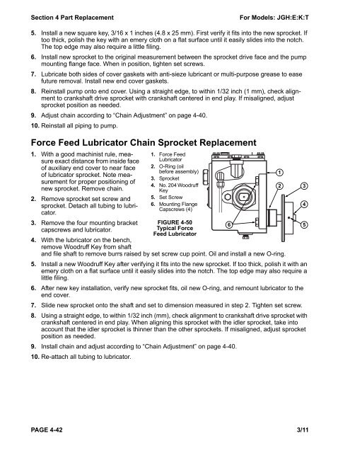
Section 4 Part Replacement For Models: JGH:E:K:T 5. Install a new square key, 3/16 x 1 inches (4.8 x 25 mm). First verify it fits into the new sprocket. If too thick, polish the key with an emery cloth on a flat surface until it easily slides into the notch. The top edge may also require a little filing. 6. Install new sprocket to the original measurement between the sprocket drive face and the pump mounting flange face. When in position, tighten set screws. 7. Lubricate both sides of cover gaskets with anti-sieze lubricant or multi-purpose grease to ease future removal. Install new end cover gaskets. 8. Reinstall pump onto end cover. Using a straight edge, to within 1/32 inch (1 mm), check alignment to crankshaft drive sprocket with crankshaft centered in end play. If misaligned, adjust sprocket position as needed. 9. Adjust chain according to “Chain Adjustment” on page 4-40. 10. Reinstall all piping to pump. Force Feed Lubricator Chain Sprocket Replacement 1. With a good machinist rule, measure exact distance from inside face of auxiliary end cover to near face of lubricator sprocket. Note measurement for proper positioning of new sprocket. Remove chain. 2. Remove sprocket set screw and sprocket. Detach all tubing to lubricator. 3. Remove the four mounting bracket capscrews and lubricator. 1. Force Feed Lubricator 2. O-Ring (oil before assembly) 3. Sprocket 4. No. 204 Woodruff Key 5. Set Screw 6. Mounting Flange Capscrews (4) FIGURE 4-50 Typical Force Feed Lubricator 4. With the lubricator on the bench, remove Woodruff Key from shaft and file shaft to remove burrs raised by set screw cup point. Oil and install a new O-ring. 5. Install a new Woodruff Key after verifying it fits into the new sprocket. If too thick, polish it with an emery cloth on a flat surface until it easily slides into the notch. The top edge may also require a little filing. 6. After new key installation, verify new sprocket fits, oil new O-ring, and remount lubricator to the end cover. 7. Slide new sprocket onto the shaft and set to dimension measured in step 2. Tighten set screw. 8. Using a straight edge, to within 1/32 inch (mm), check alignment to crankshaft drive sprocket with crankshaft centered in end play. When aligning this sprocket with the idler sprocket, take into account that the idler sprocket is thinner than the other sprockets. If misaligned, adjust sprocket position as needed. 9. Install chain and adjust according to “Chain Adjustment” on page 4-40. 10. Re-attach all tubing to lubricator. PAGE 4-42 3/11 6 1 2 3 4 5
For Models: JGH:E:K:T Section 4 Part Replacement Ethylene Glycol Contamination Compressor ethylene glycol contamination can result from water-cooled compressor rod packing or oil cooler. Ethylene glycol anti-freeze coolant mixture leaking into the compressor crankcase oil can cause crankshaft seizure due to lack of adequate lubrication. Change crankcase oil as recommended in Section 3, and routinely sample it and have a qualified lab analyze it for suitability for continued use and ethylene glycol contamination. Even small quantities of ethylene glycol in the oil can be detrimental. For contamination less than 5%, drain oil, replace filters, and flush oil system with a 50-50 mixture of butoxyethanol (Dow Chemical Co. Dowanol EB or equal) and 10W oil using a motor driven pump. Flush only warm compressors. Flush bearings continuously for 1/2 hour while barring over compressor. Flush all surfaces that contact crankcase oil, which includes spraying all interior surfaces in the crankcase. Completely drain cleaning mixture, including all oil system components. Repeat flushing with a 60/40 mixture of 10W oil and kerosene or fuel oil. Completely drain system, install new filters, and fill crankcase with proper oil. Find and repair the coolant leak. If sampling indicates glycol contamination greater than 5% or compressor seizes due to contamination, tear down the unit, clean it with 100% butoxyethanol, flush it with kerosene or fuel oil, and repair it. Clean all surfaces that contact crankcase oil with butoxyethanol, including all passages and piping, and then flush with kerosene or fuel oil. Change oil and filters. Find and repair the coolant leak. CAUTION: Butoxyethanol presents health and safety hazards. Use proper eye and skin protection and adequate ventilation. Do not use near open flame or sparks. See manufacturer Material Safety Data Sheet for complete details. Use a chemical disposal service to properly dispose of ethylene glycol, butoxyethanol, contaminated oils, and solvents. Component Cleaning and Thread Lube for Non- Lube Compressor Cylinders Ariel cleans and protects complete non-lube cylinders to non-lube service requirements. Clean all internal parts shipped loose, contaminated internal surfaces, and repair parts prior to installation, to extend the life of rings and non-lube compressors. Clean cylinder bore thoroughly with denatured alcohol until a clean, alcohol-soaked, white paper towel removes no more debris. This includes all surfaces of the bore, counter bore, valve pockets, etc. Do not use Never-Seez on steel gaskets. Apply only a very light film of oil to cylinder seating surfaces to seal O-rings. CAUTION: Denatured alcohol presents health and safety hazards. It contains methyl alcohol and is poisonous if ingested. Avoid eye and skin contact. Keep alcohol away from heat, sparks, flame and all other ignition sources. Use adequate ventilation, neoprene or butyl gloves, mono-goggles or face-mask and impermeable apron. Handle and dispose of materials resulting from clean-up in a proper manner. See manufacturer's Material Safety Data Sheets for more details. Do not use any lubricants or anti-seize compounds on parts that may contact the gas stream. Use very small amounts of Never-Seez regular grade on nut and collar when assembling piston assembly. Thoroughly clean piston (especially the ring grooves) with denatured alcohol until a clean, alcohol-soaked towel removes no more debris. Disassemble packing case. Wipe all surfaces clean with denatured alcohol. Re-assemble. When the packing case is water cooled, re-assemble and test to “Water-Cooled Piston Rod Packing” on page 4-23. Handle cleaned parts with new or clean "rubber" or new white cotton gloves. 3/11 PAGE 4-43
- Page 48 and 49: Section 3 - Maintenance For Models:
- Page 50 and 51: Section 3 - Maintenance For Models:
- Page 52 and 53: Section 3 - Maintenance For Models:
- Page 54 and 55: Section 3 - Maintenance For Models:
- Page 56 and 57: Section 3 - Maintenance For Models:
- Page 58 and 59: Section 4 Part Replacement For Mode
- Page 60 and 61: Section 4 Part Replacement For Mode
- Page 62 and 63: Section 4 Part Replacement For Mode
- Page 64 and 65: Section 4 Part Replacement For Mode
- Page 66 and 67: Section 4 Part Replacement For Mode
- Page 68 and 69: Section 4 Part Replacement For Mode
- Page 70 and 71: Section 4 Part Replacement For Mode
- Page 72 and 73: Section 4 Part Replacement For Mode
- Page 74 and 75: Section 4 Part Replacement For Mode
- Page 76 and 77: Section 4 Part Replacement For Mode
- Page 78 and 79: Section 4 Part Replacement For Mode
- Page 80 and 81: Section 4 Part Replacement For Mode
- Page 82 and 83: Section 4 Part Replacement For Mode
- Page 84 and 85: Section 4 Part Replacement For Mode
- Page 86 and 87: Section 4 Part Replacement For Mode
- Page 88 and 89: Section 4 Part Replacement For Mode
- Page 90 and 91: Section 4 Part Replacement For Mode
- Page 92 and 93: Section 4 Part Replacement For Mode
- Page 94 and 95: Section 4 Part Replacement For Mode
- Page 96 and 97: Section 4 Part Replacement For Mode
- Page 100 and 101: Section 4 Part Replacement For Mode
- Page 102 and 103: Section 5 - Start Up For Models: JG
- Page 104 and 105: Section 5 - Start Up For Models: JG
- Page 106 and 107: Section 5 - Start Up For Models: JG
- Page 108 and 109: Section 5 - Start Up For Models: JG
- Page 110 and 111: Section 5 - Start Up For Models: JG
- Page 112 and 113: Section 6 - Troubleshooting For Mod
- Page 114 and 115: Section 6 - Troubleshooting For Mod
- Page 116 and 117: Appendix A Ariel Fasteners and Torq
- Page 118 and 119: Appendix A Ariel Fasteners and Torq
- Page 120 and 121: Appendix A Ariel Fasteners and Torq
- Page 122 and 123: Appendix B - Clearances For Models:
- Page 124 and 125: Appendix B - Clearances For Models:
- Page 126 and 127: Appendix B - Clearances For Models:
- Page 128 and 129: Appendix C - Frame Specifications F
- Page 130 and 131: Appendix C - Frame Specifications F
- Page 132: Appendix D Compressor Clearance, Oi
Section 4 Part Replacement For Models: JGH:E:K:T<br />
5. Install a new square key, 3/16 x 1 inches (4.8 x 25 mm). First verify it fits into the new sprocket. If<br />
too thick, polish the key with an emery cloth on a flat surface until it easily slides into the notch.<br />
The top edge may also require a little filing.<br />
6. Install new sprocket to the original measurement between the sprocket drive face and the pump<br />
mounting flange face. When in position, tighten set screws.<br />
7. Lubricate both sides of cover gaskets with anti-sieze lubricant or multi-purpose grease to ease<br />
future removal. Install new end cover gaskets.<br />
8. Reinstall pump onto end cover. Using a straight edge, to within 1/32 inch (1 mm), check alignment<br />
to crankshaft drive sprocket with crankshaft centered in end play. If misaligned, adjust<br />
sprocket position as needed.<br />
9. Adjust chain according to “Chain Adjustment” on page 4-40.<br />
10. Reinstall all piping to pump.<br />
Force Feed Lubricator Chain Sprocket Replacement<br />
1. With a good machinist rule, measure<br />
exact distance from inside face<br />
of auxiliary end cover to near face<br />
of lubricator sprocket. Note measurement<br />
for proper positioning of<br />
new sprocket. Remove chain.<br />
2. Remove sprocket set screw and<br />
sprocket. Detach all tubing to lubricator.<br />
3. Remove the four mounting bracket<br />
capscrews and lubricator.<br />
1. Force Feed<br />
Lubricator<br />
2. O-Ring (oil<br />
before assembly)<br />
3. Sprocket<br />
4. No. 204 Woodruff<br />
Key<br />
5. Set Screw<br />
6. Mounting Flange<br />
Capscrews (4)<br />
FIGURE 4-50<br />
Typical Force<br />
Feed Lubricator<br />
4. With the lubricator on the bench,<br />
remove Woodruff Key from shaft<br />
and file shaft to remove burrs raised by set screw cup point. Oil and install a new O-ring.<br />
5. Install a new Woodruff Key after verifying it fits into the new sprocket. If too thick, polish it with an<br />
emery cloth on a flat surface until it easily slides into the notch. The top edge may also require a<br />
little filing.<br />
6. After new key installation, verify new sprocket fits, oil new O-ring, and remount lubricator to the<br />
end cover.<br />
7. Slide new sprocket onto the shaft and set to dimension measured in step 2. Tighten set screw.<br />
8. Using a straight edge, to within 1/32 inch (mm), check alignment to crankshaft drive sprocket with<br />
crankshaft centered in end play. When aligning this sprocket with the idler sprocket, take into<br />
account that the idler sprocket is thinner than the other sprockets. If misaligned, adjust sprocket<br />
position as needed.<br />
9. Install chain and adjust according to “Chain Adjustment” on page 4-40.<br />
10. Re-attach all tubing to lubricator.<br />
PAGE 4-42 3/11<br />
6<br />
1<br />
2 3<br />
4<br />
5


