Heavy Duty Balanced Opposed Compressors - Ariel Corporation
Heavy Duty Balanced Opposed Compressors - Ariel Corporation Heavy Duty Balanced Opposed Compressors - Ariel Corporation
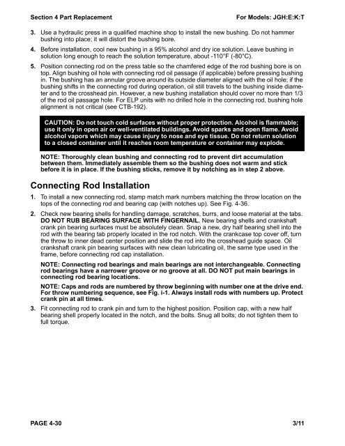
Section 4 Part Replacement For Models: JGH:E:K:T 3. Use a hydraulic press in a qualified machine shop to install the new bushing. Do not hammer bushing into place; it will distort the bushing bore. 4. Before installation, cool new bushing in a 95% alcohol and dry ice solution. Leave bushing in solution long enough to reach the solution temperature, about -110°F (-80°C). 5. Position connecting rod on the press table so the chamfered edge of the rod bushing bore is on top. Align bushing oil hole with connecting rod oil passage (if applicable) before pressing bushing in. The bushing has an annular groove around its outside diameter aligned with the oil hole; if the bushing shifts in the connecting rod during operation, oil still travels to the bushing inside diameter and to the crosshead pin. However, a new bushing installation should cover no more than 1/3 of the rod oil passage hole. For ELP units with no drilled hole in the connecting rod, bushing hole alignment is not critical (see CTB-192). CAUTION: Do not touch cold surfaces without proper protection. Alcohol is flammable; use it only in open air or well-ventilated buildings. Avoid sparks and open flame. Avoid alcohol vapors which may cause injury to nose and eye tissue. Do not return solution to a closed container until it reaches room temperature or container may explode. NOTE: Thoroughly clean bushing and connecting rod to prevent dirt accumulation between them. Immediately assemble them so the bushing does not warm and stick before it is in place. If the bushing sticks, remove it by notching as in step 2 above. Connecting Rod Installation 1. To install a new connecting rod, stamp match mark numbers matching the throw location on the tops of the connecting rod and bearing cap (with notches up). See Fig. 4-36. 2. Check new bearing shells for handling damage, scratches, burrs, and loose material at the tabs. DO NOT RUB BEARING SURFACE WITH FINGERNAIL. New bearing shells and crankshaft crank pin bearing surfaces must be absolutely clean. Snap a new, dry half bearing shell into the rod with the bearing tab properly located in the rod notch. With the crankcase top cover off, turn the throw to inner dead center position and slide the rod into the crosshead guide space. Oil crankshaft crank pin bearing surfaces with new clean lubricating oil, the same type used in the frame, before connecting rod cap installation. NOTE: Connecting rod bearings and main bearings are not interchangeable. Connecting rod bearings have a narrower groove or no groove at all. DO NOT put main bearings in connecting rod bearing locations. NOTE: Caps and rods are numbered by throw beginning with number one at the drive end. For throw numbering sequence, see Fig. i-1. Always install rods with numbers up. Protect crank pin at all times. 3. Fit connecting rod to crank pin and turn to the highest position. Position cap, with a new half bearing shell properly located in the notch, and the bolts. Snug all bolts; do not tighten them to full torque. PAGE 4-30 3/11
For Models: JGH:E:K:T Section 4 Part Replacement 4. Reconnect rod and crosshead with pin. Install end plates, thrubolt, and new lock nut. Tighten lock nut to the torque listed in Table A-3 in Appendix A. 5. Follow the torquing procedure in Appendix A to tighten connecting rod cap screws to the recommended torque in Table A-3. Then use the turn indicator tool (see Fig. 1- 1) to tighten the bolts to the recommended turn value. 6. Measure each connecting rod bearing to crankshaft jack clearance and connecting rod thrust (side) clearance (see “Connecting Rod Bearing Removal and Installation” on page 4-28). Record measurements on a copy of the form in Appendix D. If measurements are out of tolerance after installing new bearings, contact your packager or Ariel before proceeding 7. Reinstall spacer bars. All spacer bars are match-marked for proper location; reinstall them in their original location. Tighten all spacer bar bolts to the torque listed in Table A-3 in Appendix A. 8. Examine top cover and side cover gaskets. If there is doubt about their condition, replace them. Lubricate both sides of cover gaskets with anti-sieze lubricant or multi-purpose grease to ease future removal. Replace top cover and crosshead guide cover. Tighten all capscrews hand wrench tight. Crankshaft Crankshaft Removal Tighten connecting rod bolting to torque values in Table A- 3 in Appendix A. Then, start with first level vial facing up with bubble centered. Tighten thumb screw on to wrench socket and turn bolts with socket an additional 1/4 turn, until the second vial is horizontal with bubble centered. 1/4 Turn (90°) Correct rod orientation is with bearing notches on top joint. Note: Install joint match marks up. FIGURE 4-36 Connecting Rod - Typical 1. Remove coupling disk pack. Remove coupling hub. It may be necessary to heat the hub to remove it; wear insulated gloves. If the hub is not removed, the drive end cover cannot be removed and must lift out with the crankshaft. 2. Remove top cover, spacer bars, and drive end cover. TIP: If spacer bar bolts are difficult to loosen, use a 12-point hammer wrench. 3. Do not damage the sharp corners on each end of the crankcase top. They form a junction between the end covers, top cover, and base; keep them sharp and unmarred to prevent oil leaks. 4. Detach connecting rods and move them to their full outer position. 3/11 PAGE 4-31
- Page 36 and 37: Section 3 - Maintenance For Models:
- Page 38 and 39: Section 3 - Maintenance For Models:
- Page 40 and 41: Section 3 - Maintenance For Models:
- Page 42 and 43: Section 3 - Maintenance For Models:
- Page 44 and 45: Section 3 - Maintenance For Models:
- Page 46 and 47: Section 3 - Maintenance For Models:
- Page 48 and 49: Section 3 - Maintenance For Models:
- Page 50 and 51: Section 3 - Maintenance For Models:
- Page 52 and 53: Section 3 - Maintenance For Models:
- Page 54 and 55: Section 3 - Maintenance For Models:
- Page 56 and 57: Section 3 - Maintenance For Models:
- Page 58 and 59: Section 4 Part Replacement For Mode
- Page 60 and 61: Section 4 Part Replacement For Mode
- Page 62 and 63: Section 4 Part Replacement For Mode
- Page 64 and 65: Section 4 Part Replacement For Mode
- Page 66 and 67: Section 4 Part Replacement For Mode
- Page 68 and 69: Section 4 Part Replacement For Mode
- Page 70 and 71: Section 4 Part Replacement For Mode
- Page 72 and 73: Section 4 Part Replacement For Mode
- Page 74 and 75: Section 4 Part Replacement For Mode
- Page 76 and 77: Section 4 Part Replacement For Mode
- Page 78 and 79: Section 4 Part Replacement For Mode
- Page 80 and 81: Section 4 Part Replacement For Mode
- Page 82 and 83: Section 4 Part Replacement For Mode
- Page 84 and 85: Section 4 Part Replacement For Mode
- Page 88 and 89: Section 4 Part Replacement For Mode
- Page 90 and 91: Section 4 Part Replacement For Mode
- Page 92 and 93: Section 4 Part Replacement For Mode
- Page 94 and 95: Section 4 Part Replacement For Mode
- Page 96 and 97: Section 4 Part Replacement For Mode
- Page 98 and 99: Section 4 Part Replacement For Mode
- Page 100 and 101: Section 4 Part Replacement For Mode
- Page 102 and 103: Section 5 - Start Up For Models: JG
- Page 104 and 105: Section 5 - Start Up For Models: JG
- Page 106 and 107: Section 5 - Start Up For Models: JG
- Page 108 and 109: Section 5 - Start Up For Models: JG
- Page 110 and 111: Section 5 - Start Up For Models: JG
- Page 112 and 113: Section 6 - Troubleshooting For Mod
- Page 114 and 115: Section 6 - Troubleshooting For Mod
- Page 116 and 117: Appendix A Ariel Fasteners and Torq
- Page 118 and 119: Appendix A Ariel Fasteners and Torq
- Page 120 and 121: Appendix A Ariel Fasteners and Torq
- Page 122 and 123: Appendix B - Clearances For Models:
- Page 124 and 125: Appendix B - Clearances For Models:
- Page 126 and 127: Appendix B - Clearances For Models:
- Page 128 and 129: Appendix C - Frame Specifications F
- Page 130 and 131: Appendix C - Frame Specifications F
- Page 132: Appendix D Compressor Clearance, Oi
Section 4 Part Replacement For Models: JGH:E:K:T<br />
3. Use a hydraulic press in a qualified machine shop to install the new bushing. Do not hammer<br />
bushing into place; it will distort the bushing bore.<br />
4. Before installation, cool new bushing in a 95% alcohol and dry ice solution. Leave bushing in<br />
solution long enough to reach the solution temperature, about -110°F (-80°C).<br />
5. Position connecting rod on the press table so the chamfered edge of the rod bushing bore is on<br />
top. Align bushing oil hole with connecting rod oil passage (if applicable) before pressing bushing<br />
in. The bushing has an annular groove around its outside diameter aligned with the oil hole; if the<br />
bushing shifts in the connecting rod during operation, oil still travels to the bushing inside diameter<br />
and to the crosshead pin. However, a new bushing installation should cover no more than 1/3<br />
of the rod oil passage hole. For ELP units with no drilled hole in the connecting rod, bushing hole<br />
alignment is not critical (see CTB-192).<br />
CAUTION: Do not touch cold surfaces without proper protection. Alcohol is flammable;<br />
use it only in open air or well-ventilated buildings. Avoid sparks and open flame. Avoid<br />
alcohol vapors which may cause injury to nose and eye tissue. Do not return solution<br />
to a closed container until it reaches room temperature or container may explode.<br />
NOTE: Thoroughly clean bushing and connecting rod to prevent dirt accumulation<br />
between them. Immediately assemble them so the bushing does not warm and stick<br />
before it is in place. If the bushing sticks, remove it by notching as in step 2 above.<br />
Connecting Rod Installation<br />
1. To install a new connecting rod, stamp match mark numbers matching the throw location on the<br />
tops of the connecting rod and bearing cap (with notches up). See Fig. 4-36.<br />
2. Check new bearing shells for handling damage, scratches, burrs, and loose material at the tabs.<br />
DO NOT RUB BEARING SURFACE WITH FINGERNAIL. New bearing shells and crankshaft<br />
crank pin bearing surfaces must be absolutely clean. Snap a new, dry half bearing shell into the<br />
rod with the bearing tab properly located in the rod notch. With the crankcase top cover off, turn<br />
the throw to inner dead center position and slide the rod into the crosshead guide space. Oil<br />
crankshaft crank pin bearing surfaces with new clean lubricating oil, the same type used in the<br />
frame, before connecting rod cap installation.<br />
NOTE: Connecting rod bearings and main bearings are not interchangeable. Connecting<br />
rod bearings have a narrower groove or no groove at all. DO NOT put main bearings in<br />
connecting rod bearing locations.<br />
NOTE: Caps and rods are numbered by throw beginning with number one at the drive end.<br />
For throw numbering sequence, see Fig. i-1. Always install rods with numbers up. Protect<br />
crank pin at all times.<br />
3. Fit connecting rod to crank pin and turn to the highest position. Position cap, with a new half<br />
bearing shell properly located in the notch, and the bolts. Snug all bolts; do not tighten them to<br />
full torque.<br />
PAGE 4-30 3/11


