Heavy Duty Balanced Opposed Compressors - Ariel Corporation
Heavy Duty Balanced Opposed Compressors - Ariel Corporation Heavy Duty Balanced Opposed Compressors - Ariel Corporation
Section 4 Part Replacement For Models: JGH:E:K:T damage to the scraping edges. If packing case is “water”-cooled, see “Water-Cooled Piston Rod Packing” on page 4-23. 6. Lay out parts on a work bench for progressive installation, with each part in its correct position and the rod rings with their proper faces toward the pressure. Three long tie studs hold the pressure packing together. The stud holes are unequally spaced to prevent misalignment of the stack of parts. Note that all rod ring segments are carefully lettered; assemble them accordingly. This is most important for proper sealing. Center side-loaded WAT and AL rings prior to tightening tie stud nuts. Install tie nuts and tighten to the values in Table A-3 in Appendix A. Manually verify all rings move freely, radially, in their grooves. Side-loaded rings are snug, but should still move manually. Center these rings. 7. For new installations, carefully clean all accumulated dirt in the lines and compressor. Any foreign material lodges in the packing and becomes destructively abrasive. 8. Prior to packing case installation, inspect end cup gasket for nicks and damage that may cause leakage. If in doubt, replace the gasket. Verify the gasket surface in the packing counter bore on the crank end of the cylinder/head is clean and not scratched. 9. Reinstall complete packing case assembly with oil supply point on top. Use rod packing bolts to pull packing into place. 10. Reinstall packing diaphragm (if applicable) and wiper packing. 11. Reinstall piston and rod. See “Piston and Rod Installation” on page 4-14. 12. After tightening the crosshead nut, tighten rod packing bolts evenly to the recommended torque in Table A-3 in Appendix A. This procedure squares the pressure packing on its nose gasket. To align the packing, use feelers to maintain a uniform clearance all around between the case bore and the rod. Rod packing bolt tightening on high pressure cylinders requires a torque multiplier. NOTE: Repeat final torque for rod packing bolts until the bolts no longer turn. Re-check torque on these fasteners at the next service interval. 13. Retighten tie stud nuts. Reinstall tubing connections and instruments (if applicable). Take care not to cross-thread tubing nuts. Tubing nuts must be tight. NOTE: After pressure packing installation, see “Force Feed Lubricator” on page 3-15 to prime the force feed lube system and obtain recommended lubrication rates for new machine breakin. Repeat priming each time a compressor is started because oil lines may bleed during down time. Break-in lube rates are approximately twice the normal rates, or half the normal indicator pin cycle time. Long Two-Compartment Intermediate Packing Compressors supplied with long two-compartment distance pieces include an intermediate packing assembly that seals around the rod between the outboard and inboard distance pieces. This packing assembly includes a single AL ring set. For lubricated service, the force feed lube oils the top of the ring set at a very low rate because this ring set is not subject to cylinder pressures and temperatures. The end-to-end seal in the cup and the low lube rate of AL ring sets, ensures newly installed rings run virtually dry for the first few hours of operation. To avoid damage to the rings and rod, copiously oil the ring set during installation, before rod installation. Use only the same lubricant in the force feed lube system. If non-lube, see “Component Cleaning and Thread Lube for Non-Lube Compressor Cylinders” on page 4-43. PAGE 4-18 3/11
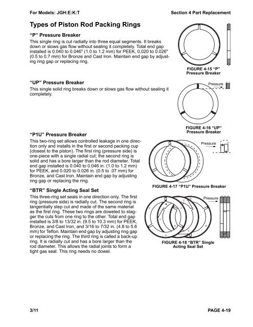
For Models: JGH:E:K:T Section 4 Part Replacement Types of Piston Rod Packing Rings “P” Pressure Breaker This single ring is cut radially into three equal segments. It breaks down or slows gas flow without sealing it completely. Total end gap installed is 0.040 to 0.046" (1.0 to 1.2 mm) for PEEK, 0.020 to 0.026" (0.5 to 0.7 mm) for Bronze and Cast Iron. Maintain end gap by adjusting ring gap or replacing ring. “UP” Pressure Breaker This single solid ring breaks down or slows gas flow without sealing it completely. “P1U” Pressure Breaker This two-ring set allows controlled leakage in one direction only and installs in the first or second packing cup (closest to the piston). The first ring (pressure side) is one-piece with a single radial cut; the second ring is solid and has a bore larger than the rod diameter. Total end gap installed is 0.040 to 0.046 in. (1.0 to 1.2 mm) for PEEK, and 0.020 to 0.026 in. (0.5 to .07 mm) for Bronze, and Cast Iron. Maintain end gap by adjusting ring gap or replacing the ring. “BTR” Single Acting Seal Set This three-ring set seals in one direction only. The first ring (pressure side) is radially cut. The second ring is tangentially step cut and made of the same material as the first ring. These two rings are doweled to stagger the cuts from one ring to the other. Total end gap installed is 3/8 to 13/32 in. (9.5 to 10.3 mm) for PEEK, Bronze, and Cast Iron, and 3/16 to 7/32 in. (4.8 to 5.6 mm) for Teflon. Maintain end gap by adjusting ring gap or replacing the ring. The third ring is called a back-up ring. It is radially cut and has a bore larger than the rod diameter. This allows the radial joints to form a tight gas seal. This ring needs no dowel. FIGURE 4-15 “P” Pressure Breaker Pressure FIGURE 4-16 “UP” Pressure Breaker Pressure FIGURE 4-17 “P1U” Pressure Breaker D D 3/11 PAGE 4-19 A D M A FIGURE 4-18 “BTR” Single Acting Seal Set M A Pressure M
- Page 24 and 25: Section 2 - Instrumentation For Mod
- Page 26 and 27: Section 2 - Instrumentation For Mod
- Page 28 and 29: Section 2 - Instrumentation For Mod
- Page 30 and 31: Section 2 - Instrumentation For Mod
- Page 32 and 33: Section 3 - Maintenance For Models:
- Page 34 and 35: Section 3 - Maintenance For Models:
- Page 36 and 37: Section 3 - Maintenance For Models:
- Page 38 and 39: Section 3 - Maintenance For Models:
- Page 40 and 41: Section 3 - Maintenance For Models:
- Page 42 and 43: Section 3 - Maintenance For Models:
- Page 44 and 45: Section 3 - Maintenance For Models:
- Page 46 and 47: Section 3 - Maintenance For Models:
- Page 48 and 49: Section 3 - Maintenance For Models:
- Page 50 and 51: Section 3 - Maintenance For Models:
- Page 52 and 53: Section 3 - Maintenance For Models:
- Page 54 and 55: Section 3 - Maintenance For Models:
- Page 56 and 57: Section 3 - Maintenance For Models:
- Page 58 and 59: Section 4 Part Replacement For Mode
- Page 60 and 61: Section 4 Part Replacement For Mode
- Page 62 and 63: Section 4 Part Replacement For Mode
- Page 64 and 65: Section 4 Part Replacement For Mode
- Page 66 and 67: Section 4 Part Replacement For Mode
- Page 68 and 69: Section 4 Part Replacement For Mode
- Page 70 and 71: Section 4 Part Replacement For Mode
- Page 72 and 73: Section 4 Part Replacement For Mode
- Page 76 and 77: Section 4 Part Replacement For Mode
- Page 78 and 79: Section 4 Part Replacement For Mode
- Page 80 and 81: Section 4 Part Replacement For Mode
- Page 82 and 83: Section 4 Part Replacement For Mode
- Page 84 and 85: Section 4 Part Replacement For Mode
- Page 86 and 87: Section 4 Part Replacement For Mode
- Page 88 and 89: Section 4 Part Replacement For Mode
- Page 90 and 91: Section 4 Part Replacement For Mode
- Page 92 and 93: Section 4 Part Replacement For Mode
- Page 94 and 95: Section 4 Part Replacement For Mode
- Page 96 and 97: Section 4 Part Replacement For Mode
- Page 98 and 99: Section 4 Part Replacement For Mode
- Page 100 and 101: Section 4 Part Replacement For Mode
- Page 102 and 103: Section 5 - Start Up For Models: JG
- Page 104 and 105: Section 5 - Start Up For Models: JG
- Page 106 and 107: Section 5 - Start Up For Models: JG
- Page 108 and 109: Section 5 - Start Up For Models: JG
- Page 110 and 111: Section 5 - Start Up For Models: JG
- Page 112 and 113: Section 6 - Troubleshooting For Mod
- Page 114 and 115: Section 6 - Troubleshooting For Mod
- Page 116 and 117: Appendix A Ariel Fasteners and Torq
- Page 118 and 119: Appendix A Ariel Fasteners and Torq
- Page 120 and 121: Appendix A Ariel Fasteners and Torq
- Page 122 and 123: Appendix B - Clearances For Models:
For Models: JGH:E:K:T Section 4 Part Replacement<br />
Types of Piston Rod Packing Rings<br />
“P” Pressure Breaker<br />
This single ring is cut radially into three equal segments. It breaks<br />
down or slows gas flow without sealing it completely. Total end gap<br />
installed is 0.040 to 0.046" (1.0 to 1.2 mm) for PEEK, 0.020 to 0.026"<br />
(0.5 to 0.7 mm) for Bronze and Cast Iron. Maintain end gap by adjusting<br />
ring gap or replacing ring.<br />
“UP” Pressure Breaker<br />
This single solid ring breaks down or slows gas flow without sealing it<br />
completely.<br />
“P1U” Pressure Breaker<br />
This two-ring set allows controlled leakage in one direction<br />
only and installs in the first or second packing cup<br />
(closest to the piston). The first ring (pressure side) is<br />
one-piece with a single radial cut; the second ring is<br />
solid and has a bore larger than the rod diameter. Total<br />
end gap installed is 0.040 to 0.046 in. (1.0 to 1.2 mm)<br />
for PEEK, and 0.020 to 0.026 in. (0.5 to .07 mm) for<br />
Bronze, and Cast Iron. Maintain end gap by adjusting<br />
ring gap or replacing the ring.<br />
“BTR” Single Acting Seal Set<br />
This three-ring set seals in one direction only. The first<br />
ring (pressure side) is radially cut. The second ring is<br />
tangentially step cut and made of the same material<br />
as the first ring. These two rings are doweled to stagger<br />
the cuts from one ring to the other. Total end gap<br />
installed is 3/8 to 13/32 in. (9.5 to 10.3 mm) for PEEK,<br />
Bronze, and Cast Iron, and 3/16 to 7/32 in. (4.8 to 5.6<br />
mm) for Teflon. Maintain end gap by adjusting ring gap<br />
or replacing the ring. The third ring is called a back-up<br />
ring. It is radially cut and has a bore larger than the<br />
rod diameter. This allows the radial joints to form a<br />
tight gas seal. This ring needs no dowel.<br />
FIGURE 4-15 “P”<br />
Pressure Breaker<br />
Pressure<br />
FIGURE 4-16 “UP”<br />
Pressure Breaker<br />
Pressure<br />
FIGURE 4-17 “P1U” Pressure Breaker<br />
D D<br />
3/11 PAGE 4-19<br />
A<br />
D<br />
M<br />
A<br />
FIGURE 4-18 “BTR” Single<br />
Acting Seal Set<br />
M<br />
A<br />
Pressure<br />
M


