

Heavy Duty Balanced Opposed Compressors - Ariel Corporation
Heavy Duty Balanced Opposed Compressors - Ariel Corporation
Heavy Duty Balanced Opposed Compressors - Ariel Corporation

You also want an ePaper? Increase the reach of your titles
YUMPU automatically turns print PDFs into web optimized ePapers that Google loves.
For Models: JGH:E:K:T Section 4 Part Replacement<br />
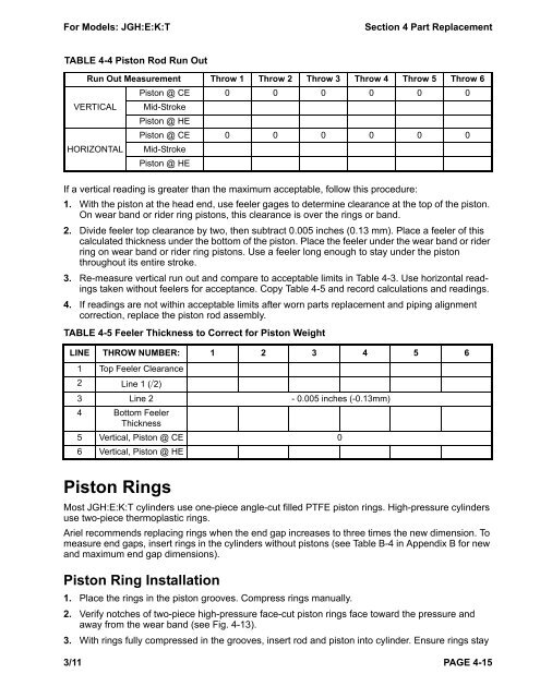
TABLE 4-4 Piston Rod Run Out<br />
Run Out Measurement Throw 1 Throw 2 Throw 3 Throw 4 Throw 5 Throw 6<br />
VERTICAL<br />
HORIZONTAL<br />
If a vertical reading is greater than the maximum acceptable, follow this procedure:<br />
1. With the piston at the head end, use feeler gages to determine clearance at the top of the piston.<br />
On wear band or rider ring pistons, this clearance is over the rings or band.<br />
2. Divide feeler top clearance by two, then subtract 0.005 inches (0.13 mm). Place a feeler of this<br />
calculated thickness under the bottom of the piston. Place the feeler under the wear band or rider<br />
ring on wear band or rider ring pistons. Use a feeler long enough to stay under the piston<br />
throughout its entire stroke.<br />
3. Re-measure vertical run out and compare to acceptable limits in Table 4-3. Use horizontal readings<br />
taken without feelers for acceptance. Copy Table 4-5 and record calculations and readings.<br />
4. If readings are not within acceptable limits after worn parts replacement and piping alignment<br />
correction, replace the piston rod assembly.<br />
Piston Rings<br />
Piston @ CE<br />
Mid-Stroke<br />
Piston @ HE<br />
0 0 0 0 0 0<br />
Piston @ CE<br />
Mid-Stroke<br />
Piston @ HE<br />
0 0 0 0 0 0<br />
TABLE 4-5 Feeler Thickness to Correct for Piston Weight<br />
LINE THROW NUMBER: 1 2 3 4 5 6<br />
1 Top Feeler Clearance<br />
2 Line 1 (/2)<br />
3 Line 2 - 0.005 inches (-0.13mm)<br />
4 Bottom Feeler<br />
Thickness<br />
5 Vertical, Piston @ CE 0<br />
6 Vertical, Piston @ HE<br />
Most JGH:E:K:T cylinders use one-piece angle-cut filled PTFE piston rings. High-pressure cylinders<br />
use two-piece thermoplastic rings.<br />
<strong>Ariel</strong> recommends replacing rings when the end gap increases to three times the new dimension. To<br />
measure end gaps, insert rings in the cylinders without pistons (see Table B-4 in Appendix B for new<br />
and maximum end gap dimensions).<br />
Piston Ring Installation<br />
1. Place the rings in the piston grooves. Compress rings manually.<br />
2. Verify notches of two-piece high-pressure face-cut piston rings face toward the pressure and<br />
away from the wear band (see Fig. 4-13).<br />
3. With rings fully compressed in the grooves, insert rod and piston into cylinder. Ensure rings stay<br />
3/11 PAGE 4-15


