Heavy Duty Balanced Opposed Compressors - Ariel Corporation
Heavy Duty Balanced Opposed Compressors - Ariel Corporation Heavy Duty Balanced Opposed Compressors - Ariel Corporation
Section 4 Part Replacement For Models: JGH:E:K:T 5. Remove piston nut using piston nut spanner. NOTE: A small amount of gas pressure may build up within the piston during operation. It vents when the piston nut is loosened. 6. After piston nut removal, slip the piston and collar off the end of the piston rod. Manual Piston and Rod Reassembly 1. Clean all piston and rod assembly parts thoroughly. Verify piston is internally clean and dry. NOTE: Reclean and re-lubricate threads and seating surfaces when reassembling used parts. 2. Inspect parts for nicks, burrs or scratches. Dress surfaces with a fine grit stone as needed. 3. Inspect piston rod threads and collar shoulder. Clean and de-burr threads. Fit collar and nut into piston to verify the outside diameter fits and rotates freely. Install collar and nut onto piston rod to verify the inside diameter fits and rotates freely. Thread piston nut manually until the rod threads protrude to verify free thread engagement. Remove nut and collar. 4. Check piston rings and wear band to determine wear. Ariel recommends replacing rings when the end gap increases to three times the new dimension. To measure end gaps, insert rings in the cylinders without pistons. Wear band projection beyond the outer piston diameter is important. To check wear band projection, measure piston to cylinder bore clearance at the bottom of the bore; there is no need to remove the piston from the cylinder. Replace wear band before it wears enough to allow the piston to touch the cylinder bore. See technical manual appendices for all clearances and tolerances. 5. Verify the clamping fixture saddle where the clamping ring seats, the clamping ring, and the piston rod are clean, dry, and free of any oil. Even a small amount of oil can cause the piston rod to turn in the fixture during torquing, and a small amount of debris clamped under high force can damage a piston rod. 6. Clamp the piston and rod assembly in an appropriate clamping fixture using the appropriate clamping ring for the rod size. Clamp it as close to the collar as possible without fixture interference with the piston. Older, larger rods not drilled and threaded for a hydraulic torque tool are best reassembled by a qualified service center. 7. Apply a thin coat of Never-Seez Regular Grade (anti-seize and lubricating compound) to piston rod shoulder, rod collar locating bands, and collar face in contact with piston, then slide collar onto rod. 8. Apply a thin coat of Never-Seez Regular Grade to piston rod threads at the piston end. Slide piston onto rod and collar. For two-piece pistons, install a new O-ring between the piston halves and align the halves using the dowel in one half and the locating hole in the other. NOTE: Ariel machines one end of single-piece pistons 0.002 inches (0.05 mm) undersize across a 3/4 inch (20 mm) wide band for manufacturing purposes. If the piston is symmetrical and can be installed in either direction, assemble with the undersize band toward the head end. For asymmetrical pistons, assemble with the side of fewer piston ring grooves toward the head end. 9. Apply a thin coat of Never-Seez Regular Grade to piston nut threads and piston mating face. Install nut and hand tighten. PAGE 4-10 3/11
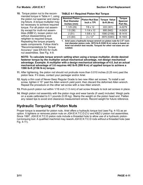
For Models: JGH:E:K:T Section 4 Part Replacement 10. Torque piston nut to the recommended torque in Table 4-1, using the piston nut spanner and clamping fixture. A torque multiplier may be necessary to achieve required torque. For all piston rod assembly except for multi-nut assemblies (KBB:V), loosen piston nut without disassembling and retighten to required torque. Repeating the torque properly seats components. Follow Ariel’s “Recommendations for Torque Accuracy” (see ER-63) for multinut assemblies. See Fig. 4-9. NOTE: To calculate torque wrench setting when using a torque multiplier, divide desired fastener torque by the multiplier actual mechanical advantage, not design mechanical advantage. Example: A multiplier with a design mechanical advantage of 4.0, but an actual mechanical advantage of 3.6 requires 442 lb-ft (599 N⋅m) of applied torque to achieve a 1590 lb-ft (2156 N⋅m) torque. 11. After tightening, the piston rod should not protrude more than 0.010 inches (0.25 mm) past the piston face. If it does, contact your packager and/or Ariel. 12. Apply a thin coat of Never-Seez Regular Grade to two new Allen set screws. To install a set screw, tighten it 15° past the Allen wrench yield point, then discard the deformed Allen wrench. Repeat the procedure on the other set screw with a new Allen wrench. 13. Prick-punch piston nut within 1/16 inch (1.5 mm) of set screw threads to lock set screws in place. 14. Weigh piston rod assembly with the piston rings and wear bands (if used) included. Weigh parts on a scale calibrated to 0.1 pounds (0.05 kg). Stamp the weight on the piston head end. Flatten any raised lips to avoid end clearance measurement errors. Record weight for future reference. Hydraulic Torquing of Piston Nuts TABLE 4-1 Required Piston Nut Torque Nominal Piston Rod Diameter Inches (mm) Piston Nut Size Inch x TPI Torque Value lb-ft (N-m) Torque Spanner Part No. 1.125 (29) 7/8 x 12 222 (301) A-0279 1.5 (38) 1-1/4 x 12 695 (942) A-0424 2 (51) 1-5/8 x 12 1590 (2156) B-1410 2.5 (64) 2 x 12 1 3970 (5383) B-1503 1. Ariel uses a hydraulic torque wrench on piston nuts for 2.5" nominal diameter piston rods. 3970 lb-ft (5383 N⋅m) value is based on Ariel rod stretch test results. Torques for other rod sizes are calculated. Proper torque is essential for piston nuts. Ariel offers a hydraulic torque tool (see Fig. 4-10) as an option. It tightens or removes piston nuts on JGH:E:K:T:C:D:Z:U and KBZ:U piston rod assemblies. Since 1997, JGH:E:K:T:C:D piston rods include a threaded hole to allow use of a hydraulic pistonnut-torquing tool. A qualified machinist may rework JGH:E:K:T:C:D rods without a threaded hole (see Fig. 4-11). 3/11 PAGE 4-11
- Page 16 and 17: Section 1 - Tools For Models: JGH:E
- Page 18 and 19: Section 2 - Instrumentation For Mod
- Page 20 and 21: Section 2 - Instrumentation For Mod
- Page 22 and 23: Section 2 - Instrumentation For Mod
- Page 24 and 25: Section 2 - Instrumentation For Mod
- Page 26 and 27: Section 2 - Instrumentation For Mod
- Page 28 and 29: Section 2 - Instrumentation For Mod
- Page 30 and 31: Section 2 - Instrumentation For Mod
- Page 32 and 33: Section 3 - Maintenance For Models:
- Page 34 and 35: Section 3 - Maintenance For Models:
- Page 36 and 37: Section 3 - Maintenance For Models:
- Page 38 and 39: Section 3 - Maintenance For Models:
- Page 40 and 41: Section 3 - Maintenance For Models:
- Page 42 and 43: Section 3 - Maintenance For Models:
- Page 44 and 45: Section 3 - Maintenance For Models:
- Page 46 and 47: Section 3 - Maintenance For Models:
- Page 48 and 49: Section 3 - Maintenance For Models:
- Page 50 and 51: Section 3 - Maintenance For Models:
- Page 52 and 53: Section 3 - Maintenance For Models:
- Page 54 and 55: Section 3 - Maintenance For Models:
- Page 56 and 57: Section 3 - Maintenance For Models:
- Page 58 and 59: Section 4 Part Replacement For Mode
- Page 60 and 61: Section 4 Part Replacement For Mode
- Page 62 and 63: Section 4 Part Replacement For Mode
- Page 64 and 65: Section 4 Part Replacement For Mode
- Page 68 and 69: Section 4 Part Replacement For Mode
- Page 70 and 71: Section 4 Part Replacement For Mode
- Page 72 and 73: Section 4 Part Replacement For Mode
- Page 74 and 75: Section 4 Part Replacement For Mode
- Page 76 and 77: Section 4 Part Replacement For Mode
- Page 78 and 79: Section 4 Part Replacement For Mode
- Page 80 and 81: Section 4 Part Replacement For Mode
- Page 82 and 83: Section 4 Part Replacement For Mode
- Page 84 and 85: Section 4 Part Replacement For Mode
- Page 86 and 87: Section 4 Part Replacement For Mode
- Page 88 and 89: Section 4 Part Replacement For Mode
- Page 90 and 91: Section 4 Part Replacement For Mode
- Page 92 and 93: Section 4 Part Replacement For Mode
- Page 94 and 95: Section 4 Part Replacement For Mode
- Page 96 and 97: Section 4 Part Replacement For Mode
- Page 98 and 99: Section 4 Part Replacement For Mode
- Page 100 and 101: Section 4 Part Replacement For Mode
- Page 102 and 103: Section 5 - Start Up For Models: JG
- Page 104 and 105: Section 5 - Start Up For Models: JG
- Page 106 and 107: Section 5 - Start Up For Models: JG
- Page 108 and 109: Section 5 - Start Up For Models: JG
- Page 110 and 111: Section 5 - Start Up For Models: JG
- Page 112 and 113: Section 6 - Troubleshooting For Mod
- Page 114 and 115: Section 6 - Troubleshooting For Mod
For Models: JGH:E:K:T Section 4 Part Replacement<br />
10. Torque piston nut to the recommended<br />
torque in Table 4-1, using<br />
the piston nut spanner and clamping<br />
fixture. A torque multiplier may<br />
be necessary to achieve required<br />
torque. For all piston rod assembly<br />
except for multi-nut assemblies<br />
(KBB:V), loosen piston nut<br />
without disassembling and<br />
retighten to required torque.<br />
Repeating the torque properly<br />
seats components. Follow <strong>Ariel</strong>’s<br />
“Recommendations for Torque<br />
Accuracy” (see ER-63) for multinut<br />
assemblies. See Fig. 4-9.<br />
NOTE: To calculate torque wrench setting when using a torque multiplier, divide desired<br />
fastener torque by the multiplier actual mechanical advantage, not design mechanical<br />
advantage. Example: A multiplier with a design mechanical advantage of 4.0, but an actual<br />
mechanical advantage of 3.6 requires 442 lb-ft (599 N⋅m) of applied torque to achieve a<br />
1590 lb-ft (2156 N⋅m) torque.<br />
11. After tightening, the piston rod should not protrude more than 0.010 inches (0.25 mm) past the<br />
piston face. If it does, contact your packager and/or <strong>Ariel</strong>.<br />
12. Apply a thin coat of Never-Seez Regular Grade to two new Allen set screws. To install a set<br />
screw, tighten it 15° past the Allen wrench yield point, then discard the deformed Allen wrench.<br />
Repeat the procedure on the other set screw with a new Allen wrench.<br />
13. Prick-punch piston nut within 1/16 inch (1.5 mm) of set screw threads to lock set screws in place.<br />
14. Weigh piston rod assembly with the piston rings and wear bands (if used) included. Weigh parts<br />
on a scale calibrated to 0.1 pounds (0.05 kg). Stamp the weight on the piston head end. Flatten<br />
any raised lips to avoid end clearance measurement errors. Record weight for future reference.<br />
Hydraulic Torquing of Piston Nuts<br />
TABLE 4-1 Required Piston Nut Torque<br />
Nominal Piston<br />
Rod Diameter<br />
Inches (mm)<br />
Piston Nut Size<br />
Inch x TPI<br />
Torque Value<br />
lb-ft (N-m)<br />
Torque<br />
Spanner<br />
Part No.<br />
1.125 (29) 7/8 x 12 222 (301) A-0279<br />
1.5 (38) 1-1/4 x 12 695 (942) A-0424<br />
2 (51) 1-5/8 x 12 1590 (2156) B-1410<br />
2.5 (64) 2 x 12 1 3970 (5383) B-1503<br />
1. <strong>Ariel</strong> uses a hydraulic torque wrench on piston nuts for 2.5" nominal<br />
diameter piston rods. 3970 lb-ft (5383 N⋅m) value is based on<br />
<strong>Ariel</strong> rod stretch test results. Torques for other rod sizes are calculated.<br />
Proper torque is essential for piston nuts. <strong>Ariel</strong> offers a hydraulic torque tool (see Fig. 4-10) as an<br />
option. It tightens or removes piston nuts on JGH:E:K:T:C:D:Z:U and KBZ:U piston rod assemblies.<br />
Since 1997, JGH:E:K:T:C:D piston rods include a threaded hole to allow use of a hydraulic pistonnut-torquing<br />
tool. A qualified machinist may rework JGH:E:K:T:C:D rods without a threaded hole (see<br />
Fig. 4-11).<br />
3/11 PAGE 4-11


