Heavy Duty Balanced Opposed Compressors - Ariel Corporation
Heavy Duty Balanced Opposed Compressors - Ariel Corporation Heavy Duty Balanced Opposed Compressors - Ariel Corporation
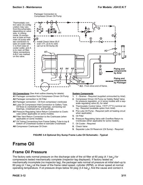
Section 3 - Maintenance For Models: JGH:E:K:T Thermostatic control valve (3) configuration may vary from this schematic, depending on valve size. In mixing mode, B connection is lube oil from main oil pump with tee connection to lube oil cooler inlet, C is from lube oil cooler outlet, and A is to main oil filter. Valve connections A-B-C are marked on the valve. Frame Oil 1 2 Frame Oil Pressure Packager Connection to Compressor Driven Oil Pump 8 Install Check Valve (8) if over 3 Ft. (0.9 m) vertical run to Oil Sump (9) 9 A7 A1 A3 A4 A8 Oil Connections (See Ariel outline drawing for details) A1 Packager connection from Compressor Driven Oil Pump A2 Packager connection to Oil Filter A3 Packager connection - Oil from compressor crankcase A4 Lube Oil Compressor-Inlet-Connection to Gallery Tube. Oil flows to crankshaft main bearings, connecting rod bearings, crosshead pins, and bushings A5 Pressure Regulating Valve Return Connection to Crankcase (when applicable on some models) A6 Filter Vent Return Connection to the Crankcase (when applicable on some models) A7 Oil Tubing Connections from Frame Gallery Tube to top & bottom of Crosshead Guides to lubricate Crossheads A8 Compressor Crankcase Oil Drain A5 A6 4 8 FIGURE 3-4 Optional Dry Sump Frame Lube Oil Schematic - Typical The factory sets normal pressure on the discharge side of the oil filter at 60 psig (4.1 bar g ) for compressors tested mechanically complete (inspector tag displayed). If factory tested as mechanically incomplete (no inspector tag), the packager sets normal oil pressure at initial start-up to 60 psig (4.1 bar g ) at the lower of the frame rated speed, cylinder (RPM), or driver speed at normal operating temperature. If oil pressure drops below 50 psig (3.4 bar g ), find the cause and correct it. PAGE 3-12 3/11 7 B A C 3 6 A2 A3 - From drive end of frame. 8 F 5 Piping and components by Ariel Piping and components by Packager System Components 1. Y - Strainer - Required (supplied unmounted by Ariel) 2. Compressor Driven Oil Pump (w/ Safety Relief Valve for pressure regulation, or in some models with a separate regulating valve (6), for relief 3. Thermostatic Control Valve, 170°F (77°C) nominal rating - Required (available option from Ariel) 4. Pre-Lube Oil Pump - Required (with oil heating circuit when applicable) 5. Oil Filter 6. Pressure Regulating Valve with Overflow Return to Crankcase (when applicable for some models) 7. Oil Cooler - Required 8. Check Valve 9. Separate Lube Oil Reservoir (Oil Sump) - Required
For Models: JGH:E:K:T Section 3 - Maintenance The compressor requires a 45 psig (3.1 barg ) low oil pressure shutdown for protection. Do not operate the compressor for prolonged periods at less than 50 psig (3.4 barg ) oil pressure. For proper operation of the thermostatic control valve, the maximum differential pressure between the hot oil supply line and the cooled oil return line is 10 psid (0.7 bard ). Frame Oil Temperature To drive off water vapor, the minimum lube oil operating temperature is 150°F (66°C). Maximum allowable oil temperature into the compressor frame is 190°F (88°C). Ariel offers a thermostatic control valve set at 170°F (77°C). Maintain oil temperature as close to this temperature as possible. Higher temperatures increase the oxidation rate of oil. Every 18°F (10°C) over 150°F (66°C) doubles the oxidation rate of oil. Frame Oil Maintenance Change compressor frame lubricating oil as indicated in the regular maintenance intervals or with a filter change or when oil analysis indicates the need. Some compressors may require more frequent oil changes if operating in an extremely dirty environment without sampling and analysis or if the oil supplier recommends it. Frame Oil Sampling Typically, packagers install an oil sampling point between the oil pump and filter at an easily accessible location. Collect and analyze oil samples to verify suitability for continued service. Consistent oil analysis can identify when to change oil on the basis of need rather than a scheduled interval. Depending on service, oil analysis can significantly extend oil change intervals. Oil analysis should include: • Viscosity testing at 100°F (40°C) and 212°F (100°C). Determines whether cylinder oils or process gas diluted the oil. • Particle counting to the latest version of ISO 4406. • Spectroscopy to determine wear metals, contaminants, and additives. • FTIR (Fourier Transform Infrared Spectroscopy) to check for oxidation, water or coolant contamination, and additive depletion. This is more important if a force feed system uses separate lube oil. Dry Sump Compressors subject to transient motion, roll, and yaw on board a ship or floating platform may require a dry crankcase with a separate oil reservoir. With a dry sump, Ariel provides drains at each end of the compressor frame and an oil pump chain oiler. The packager provides a lube oil reservoir sized and located to provide oil suction to the oil pump regardless of tilt. There should be a 30 mesh (595 microns) oil sump strainer in the pump suction line at the lube oil reservoir outlet. Remove strainer basket and wash it in an appropriate solvent whenever lubricating oil is changed. Oil System Cleanliness Clean compressor frame oil piping system and components of all foreign matter such as sand, rust, mill scale, metal chips, weld spatter, grease, and paint. Ariel recommends using a commercial pipe cleaning service to clean the oil piping system. If not practical, use proper cleaning procedures with proper cleaners, acids, and/or mechanical cleaning to meet cleanliness requirements. Dispose of cleaning by-products properly; a disposal service is recommended. Ariel also recommends flushing all oil-piping systems with an electric or pneumatic driven pump and filtered clean production oil. Ariel thoroughly cleans all compressor frame cavities prior to assembly and test runs compressors with a filtered closed loop lube system. 3/11 PAGE 3-13
- Page 1: Maintenance and Repair Manual For J
- Page 4 and 5: For Models: JGE:H:K:T Oil Strainer.
- Page 6 and 7: For Models: JGE:H:K:T SECTION 5 - S
- Page 8 and 9: For Models: JGH:E:K:T FIGURE 4-23
- Page 10 and 11: For Models: JGH:E:K:T General Safet
- Page 12 and 13: For Models: JGH:E:K:T Ariel Contact
- Page 14 and 15: Section 1 - Tools For Models: JGH:E
- Page 16 and 17: Section 1 - Tools For Models: JGH:E
- Page 18 and 19: Section 2 - Instrumentation For Mod
- Page 20 and 21: Section 2 - Instrumentation For Mod
- Page 22 and 23: Section 2 - Instrumentation For Mod
- Page 24 and 25: Section 2 - Instrumentation For Mod
- Page 26 and 27: Section 2 - Instrumentation For Mod
- Page 28 and 29: Section 2 - Instrumentation For Mod
- Page 30 and 31: Section 2 - Instrumentation For Mod
- Page 32 and 33: Section 3 - Maintenance For Models:
- Page 34 and 35: Section 3 - Maintenance For Models:
- Page 36 and 37: Section 3 - Maintenance For Models:
- Page 38 and 39: Section 3 - Maintenance For Models:
- Page 40 and 41: Section 3 - Maintenance For Models:
- Page 44 and 45: Section 3 - Maintenance For Models:
- Page 46 and 47: Section 3 - Maintenance For Models:
- Page 48 and 49: Section 3 - Maintenance For Models:
- Page 50 and 51: Section 3 - Maintenance For Models:
- Page 52 and 53: Section 3 - Maintenance For Models:
- Page 54 and 55: Section 3 - Maintenance For Models:
- Page 56 and 57: Section 3 - Maintenance For Models:
- Page 58 and 59: Section 4 Part Replacement For Mode
- Page 60 and 61: Section 4 Part Replacement For Mode
- Page 62 and 63: Section 4 Part Replacement For Mode
- Page 64 and 65: Section 4 Part Replacement For Mode
- Page 66 and 67: Section 4 Part Replacement For Mode
- Page 68 and 69: Section 4 Part Replacement For Mode
- Page 70 and 71: Section 4 Part Replacement For Mode
- Page 72 and 73: Section 4 Part Replacement For Mode
- Page 74 and 75: Section 4 Part Replacement For Mode
- Page 76 and 77: Section 4 Part Replacement For Mode
- Page 78 and 79: Section 4 Part Replacement For Mode
- Page 80 and 81: Section 4 Part Replacement For Mode
- Page 82 and 83: Section 4 Part Replacement For Mode
- Page 84 and 85: Section 4 Part Replacement For Mode
- Page 86 and 87: Section 4 Part Replacement For Mode
- Page 88 and 89: Section 4 Part Replacement For Mode
- Page 90 and 91: Section 4 Part Replacement For Mode
Section 3 - Maintenance For Models: JGH:E:K:T<br />
Thermostatic control<br />
valve (3) configuration<br />
may vary<br />
from this schematic,<br />
depending on valve<br />
size. In mixing<br />
mode, B connection<br />
is lube oil from<br />
main oil pump with<br />
tee connection to<br />
lube oil cooler inlet,<br />
C is from lube oil<br />
cooler outlet, and A<br />
is to main oil filter.<br />
Valve connections<br />
A-B-C are marked<br />
on the valve.<br />
Frame Oil<br />
1 2<br />
Frame Oil Pressure<br />
Packager Connection to<br />
Compressor Driven Oil Pump<br />
8<br />
Install Check Valve (8) if<br />
over 3 Ft. (0.9 m) vertical<br />
run to Oil Sump (9)<br />
9<br />
A7<br />
A1<br />
A3 A4 A8<br />
Oil Connections (See <strong>Ariel</strong> outline drawing for details)<br />
A1 Packager connection from Compressor Driven Oil Pump<br />
A2 Packager connection to Oil Filter<br />
A3 Packager connection - Oil from compressor crankcase<br />
A4 Lube Oil Compressor-Inlet-Connection to Gallery Tube.<br />
Oil flows to crankshaft main bearings, connecting rod<br />
bearings, crosshead pins, and bushings<br />
A5 Pressure Regulating Valve Return Connection to Crankcase<br />
(when applicable on some models)<br />
A6 Filter Vent Return Connection to the Crankcase (when<br />
applicable on some models)<br />
A7 Oil Tubing Connections from Frame Gallery Tube to top &<br />
bottom of Crosshead Guides to lubricate Crossheads<br />
A8 Compressor Crankcase Oil Drain<br />
A5 A6<br />
4 8<br />
FIGURE 3-4 Optional Dry Sump Frame Lube Oil Schematic - Typical<br />
The factory sets normal pressure on the discharge side of the oil filter at 60 psig (4.1 bar g ) for<br />
compressors tested mechanically complete (inspector tag displayed). If factory tested as<br />
mechanically incomplete (no inspector tag), the packager sets normal oil pressure at initial start-up to<br />
60 psig (4.1 bar g ) at the lower of the frame rated speed, cylinder (RPM), or driver speed at normal<br />
operating temperature. If oil pressure drops below 50 psig (3.4 bar g ), find the cause and correct it.<br />
PAGE 3-12 3/11<br />
7<br />
B<br />
A<br />
C<br />
3<br />
6<br />
A2<br />
A3 - From drive end of frame.<br />
8<br />
F<br />
5<br />
Piping and<br />
components<br />
by <strong>Ariel</strong><br />
Piping and<br />
components<br />
by Packager<br />
System Components<br />
1. Y - Strainer - Required (supplied unmounted by <strong>Ariel</strong>)<br />
2. Compressor Driven Oil Pump (w/ Safety Relief Valve<br />
for pressure regulation, or in some models with a separate<br />
regulating valve (6), for relief<br />
3. Thermostatic Control Valve, 170°F (77°C) nominal rating<br />
- Required (available option from <strong>Ariel</strong>)<br />
4. Pre-Lube Oil Pump - Required (with oil heating circuit<br />
when applicable)<br />
5. Oil Filter<br />
6. Pressure Regulating Valve with Overflow Return to<br />
Crankcase (when applicable for some models)<br />
7. Oil Cooler - Required<br />
8. Check Valve<br />
9. Separate Lube Oil Reservoir (Oil Sump) - Required


