Access Virus User Manual - SoundProgramming.Net
Access Virus User Manual - SoundProgramming.Net
Access Virus User Manual - SoundProgramming.Net

Create successful ePaper yourself
Turn your PDF publications into a flip-book with our unique Google optimized e-Paper software.
©2000 <strong>Access</strong> Music GmbH, Germany.<br />
<strong>Virus</strong> is a trademark of<br />
<strong>Access</strong> Music GmbH. All other<br />
trademarks contained herein are<br />
the property of their respective<br />
owners. All features and specifications<br />
subject to change without<br />
notice.<br />
Written by Christoph Kemper, Uwe<br />
G. Hönig, Wiland Samolak and<br />
Marc Schlaile.<br />
Translation by Thomas Green.<br />
Graphic Design and DTP by<br />
Babylonwaves Media.<br />
http://www.access-music.de<br />
info@access-music.de
CONTENT<br />
INTRODUCTION - 15<br />
The <strong>Virus</strong> ..................................................16<br />
The Amplifier Envelope ....................... 20<br />
The First Filter .........................................23<br />
Filter Modulation ...................................25<br />
The Saturation Stage ............................27<br />
The Second Filter................................... 28<br />
Filter Routing ..........................................32<br />
The First Oscillator................................ 34<br />
The Second Oscillator ...........................37<br />
The MIXER Section................................ 39<br />
The LFOs ................................................... 41<br />
LFO 2 .........................................................46<br />
Velocity .................................................... 48<br />
Unison Mode..........................................49<br />
The Chorus/Flanger Effect.................. 50<br />
The Delay Effect...................................... 51<br />
More to Come .........................................52<br />
CONCEPT AND OPERATION - 53<br />
Operating Modes .................................. 54<br />
The Multi-Single Mode.........................55<br />
Edit Buffers ..............................................57<br />
HANDLING - 59<br />
Parameter Selection and<br />
Data Entry...............................................60<br />
Knob Modes ........................................... 63<br />
Display of values ................................... 64<br />
ALL ABOUT THE MEMORY - 67<br />
Store ......................................................... 68<br />
Compare..................................................69<br />
MASTER CLOCK & MIDI-CLOCK - 71<br />
Master Clock and Midi-Clock ..............72<br />
THE MODULATION MATRIX AND<br />
DEFINABLE KNOB - 75<br />
Creating Modulation Configurations<br />
via Assign ................................................ 76<br />
The Definable Knobs.............................78<br />
THE EFFECTS SECTION - 81<br />
The Effect Section ................................. 82
AUDIO INPUTS - 83<br />
Audio Inputs........................................... 84<br />
OSC Volume / Input.............................. 85<br />
Input Level Indicator ............................86<br />
INTERNAL AUDIO ROUTING - 87<br />
Aux Buses................................................ 88<br />
The Audio Outputs ...............................89<br />
ADDITIONAL FUNCTIONS - 91<br />
Panic Function ....................................... 92<br />
Audition function.................................. 92<br />
Reset Function ....................................... 92<br />
THE PARAMETERS - 93<br />
Sound Parameters with a Dedicated<br />
Control Element ....................................94<br />
LFO 1 – Panel ........................................... 95<br />
LFO 1 – EDIT Menu................................. 97<br />
LFO 2 - Panel ......................................... 100<br />
LFO 2 Edit-Menu ................................... 101<br />
LFO 3 ........................................................102<br />
OSCILLATOR 1- Front Panel................ 104<br />
Oscillator 2 – front Panel....................105<br />
OSCILLATOR – EDIT-Menu................ 106<br />
Menu parameters for Oscillator-2...107<br />
Menu-Parameter for Oscillator-3... 109<br />
Menu-Parameters of the<br />
Suboscillator ...........................................111<br />
Mixer-Parameters within then<br />
Oscillator-edit-Menu ...........................112<br />
Mixer ........................................................ 113<br />
Filters – Panel.........................................114<br />
Filter-Edit-Menu....................................118<br />
Amplifier ................................................ 122<br />
Main Edit Menu (Common)............... 123<br />
Assign......................................................129<br />
Velocity................................................... 133<br />
WITHIN THE CTRL-MENU - 135<br />
COMMON ..............................................136<br />
ARPEGGIATOR....................................... 137<br />
DEFINABLE 1 / DEFINABLE 2 .............. 140<br />
MULTI MODE parameters.................. 142<br />
PARAMETER OF THE FX-MENU- 149<br />
The internal Effects .............................150<br />
Input........................................................150<br />
Follower (Envelope-Follower) ........... 154<br />
Ringmodulator ..................................... 155<br />
Vocoder ..................................................156<br />
Distortion............................................... 157
Analog Boost .........................................158<br />
Phaser .....................................................159<br />
Chorus..................................................... 161<br />
Delay/Reverb.........................................162<br />
THE VOCODER OF THE VIRUS - 201<br />
Vocoder ................................................. 202<br />
The parameters of the vocoder.......204<br />
Notes about the vocoder ...................210<br />
GLOBAL-, MIDI- AND SYSTEM<br />
PARAMETERS - 173<br />
Global Parameters ............................... 174<br />
System ................................................... 180<br />
RANDOM PATCH GENERATOR - 183<br />
Random Patches...................................184<br />
CATEGORIES - 187<br />
Sound Categories.................................188<br />
THE KEYBOARD VERSIONS OF<br />
THE VIRUS - 189<br />
The <strong>Virus</strong> kb and the <strong>Virus</strong> Indigo... 190<br />
Local off and “Three in One” ............ 190<br />
Keyboard & Company.........................192<br />
The Keyboard-Modes..........................195<br />
THE VIRUS AND SEQUENCERS - 213<br />
Parameter Control via MIDI .............. 214<br />
Organizational Information.............. 214<br />
Handling MIDI Parameter Control ..216<br />
Notes on Adaptive Parameter<br />
Smoothing ............................................. 217<br />
Problems Related to Parameter<br />
Control.................................................... 221<br />
DUMP: The Sound in the Song .........222<br />
TIPS, TRICKS AND OTHER WORDS<br />
OF WISDOM - 227<br />
MULTI SINGLE Mode .......................... 228<br />
Value Buttons ...................................... 229<br />
All abouts Inputs................................. 229<br />
About the Delay/Reverb..................... 231<br />
The <strong>Virus</strong> as an Effect Device............232<br />
Envelope Follower ...............................233<br />
Oscillators ............................................. 234<br />
Filters.......................................................237<br />
SATURATION for Added Dirt ............ 239
LFOs ........................................................240<br />
Volume Control ................................... 242<br />
ASSIGN and the DEFINABLE Knobs. 243<br />
ARPEGGIATOR ...................................... 244<br />
MIDI ........................................................ 245<br />
PRIORITY ................................................ 247<br />
Installing an operating system<br />
update.................................................... 247<br />
Loading the Operating System from<br />
One <strong>Virus</strong> to Another .........................249<br />
Software Updates ............................... 250<br />
APPENDIX - 251<br />
System Exclusive Data........................252<br />
Parameters Describtion..................... 258<br />
Multi Dump Table................................273<br />
Classes ................................................... 276<br />
Mod Matrix Sources ..........................280<br />
Mod Matrix Destinations...................281<br />
Definable Knobs Destinations ........ 282<br />
MIDI Implementation Chart.............284<br />
FCC Information (U.S.A).....................286<br />
FCC Information (CANADA)..............288<br />
Other Standards (Rest of World).....289<br />
Declaration of Conformity................290<br />
Garantie Bestimmung ....................... 292<br />
Warranty ............................................... 293
ACCESS VIRUS OS4 7<br />
Important Safety Remarks<br />
Please read and heed the following<br />
safety guidelines!<br />
A few fundamental rules on handling<br />
electrical devices follow.<br />
Please read all notes carefully<br />
before you power the device up.<br />
Set-up<br />
Operate and store the device in<br />
enclosed rooms only.<br />
Never expose the device to a<br />
damp environment.<br />
Never operate or store the device<br />
in extremely dusty or dirty environments.<br />
Assure that air can circulate<br />
freely on all sides of the device,<br />
especially when you mount it to a<br />
rack.<br />
Don’t set the device in the immediate<br />
vicinity of heat sources such<br />
as radiators.<br />
Don’t expose the device to direct<br />
sunlight.<br />
Don’t expose the device to<br />
strong vibrations and mechanical<br />
shocks.<br />
Connections<br />
Be sure to use exclusively the<br />
included mains power supply<br />
adapter.<br />
Plug the device only into mains<br />
sockets that are properly grounded<br />
in compliance with statutory regulations.<br />
Never modify the included<br />
power cord. If its plug does not fit<br />
the sockets you have available,<br />
take it to a qualified electrician.<br />
Always pull the power plug out<br />
of the mains socket when you<br />
won’t be using the device for prolonged<br />
periods.<br />
Never touch the mains plug with<br />
wet hands.
8 CHAPTER 2<br />
Safety Remarks<br />
Always pull the actual plug,<br />
never the cord, when you’re<br />
unplugging the device.<br />
Operation<br />
Don’t set beverages or any other<br />
receptacle containing liquids on<br />
the device.<br />
Make sure the device is placed<br />
on a solid base. Set it on a stable<br />
tabletop or mount it to a rack.<br />
Make sure that no foreign<br />
objects fall into or somehow end<br />
up inside the device’s housing. In<br />
the event that this should occur,<br />
switch the device off and pull the<br />
power plug. Then get in touch with<br />
an authorized dealer.<br />
Used on its own and in conjunction<br />
with amps, loudspeakers or<br />
headphones, this device is able to<br />
generate levels that can lead to<br />
irreversible hearing damage. For<br />
this reason, always operate it at a<br />
reasonable volume level.<br />
Memory battery change<br />
The <strong>Virus</strong> stores its sound programs<br />
in a battery-buffered RAM.<br />
This battery (general type designation:<br />
CR2032) should be replaced<br />
every three to four years. The housing<br />
has to be opened to change the<br />
battery, so take the device to a<br />
qualified service technician. Do<br />
your part in protecting our environment<br />
and take it to a shop that<br />
disposes of batteries properly.<br />
Before you have the battery<br />
changed, save the entire memory<br />
content of the RAM by loading it to<br />
a sequencer via "Total Dump". Be<br />
advised that RAM content is lost<br />
when the battery is swapped (see<br />
“Midi Dump TX” on page 174).<br />
Care<br />
Do not open the device, it is not<br />
equipped with any user-serviceable<br />
parts. Repair and maintenance<br />
may only be carried out by<br />
qualified specialists.<br />
Use only a dry, soft cloth or brush<br />
to clean the device.
ACCESS VIRUS OS4 9<br />
Do not use alcohol, solvents or<br />
similar chemicals. These can damage<br />
the surface of the housing.<br />
Fitness for Purpose<br />
This device is designed exclusively<br />
to generate low-frequency audio<br />
signals for sound engineeringrelated<br />
purposes. Any other use is<br />
not permitted and automatically<br />
invalidates the warranty extended<br />
by <strong>Access</strong> Music Electronics GmbH.
10 CHAPTER 2<br />
Safety Remarks
ACCESS VIRUS OS4 11<br />
Prologue<br />
Dear <strong>Virus</strong> Owner,<br />
Congratulations on your choice,<br />
the new <strong>Virus</strong>. You have purchased<br />
a cutting-edge synthesizer that<br />
comes fully loaded with several<br />
revolutionary features. Here are<br />
just a few of the highlights:<br />
The <strong>Virus</strong> delivers the sound characteristics<br />
and tone of traditional<br />
analog synthesizers - for instance<br />
the Prophet 5 or Memorymoog to<br />
name just two popular examples<br />
of the species - in a previously<br />
unparalleled level of quality and<br />
handling ease. We’re not kidding,<br />
the <strong>Virus</strong> actual delivers the<br />
authentic response of an analog<br />
synth via a digital signal processor<br />
chip, although the sound shaping<br />
and voicing options out-perform<br />
those of it historical predecessors<br />
by a considerable margin.<br />
The <strong>Virus</strong> comes with 512 slots for<br />
storing SINGLE sounds. These are<br />
organized in four banks. The first<br />
two banks (A and B) are located in<br />
the RAM, so you can overwrite<br />
them with new sounds. The other<br />
two banks are ”hard-wired”, i.e.<br />
they’re programmed into the<br />
FLASH ROM.<br />
The <strong>Virus</strong> offers a maximum of 24<br />
voices. In Multi Mode, these are<br />
allocated dynamically to sixteen<br />
simultaneously available sounds.<br />
You have no less than three audio<br />
oscillators plus one suboscillator, a<br />
noise generator, a ring modulator,<br />
two Multi Mode filters, two envelopes,<br />
a stereo VCA, three LFOs and<br />
a saturation stage (SATURATOR) for<br />
cascade filtering, tube and distortion<br />
effects.<br />
The <strong>Virus</strong> offers a veritable arsenal<br />
of effects. You have seven powerful<br />
sound-sculpting functions, including<br />
chorus, phaser and distortion,<br />
at your disposal, with each effect<br />
available separately for every<br />
sound. Thus, in 16-way MULTI<br />
mode, the <strong>Virus</strong> offers 80 effects,<br />
no less!. You also get a global<br />
reverb/delay unit that lets you create<br />
high-quality reverb effects and<br />
rhythmic delay taps. Delay time<br />
can be synced up to MIDI clock.
12 CHAPTER 3<br />
Prologue<br />
With the benefit of two external<br />
audio inputs, the <strong>Virus</strong> may also<br />
serve as an FX device and signal<br />
processor that you can use creatively<br />
to come up with all kinds of<br />
effects. External signals can be<br />
processed with filter, gate and lo-fi<br />
effects, routed to the <strong>Virus</strong> effects<br />
section and serve as a modulation<br />
source for frequency and ring modulation.<br />
Beyond that, you can use internal<br />
or external signals as sources for<br />
the <strong>Virus</strong>’ on-board vocoder serve.<br />
The vocoder works with up to 32<br />
filter bands and offers diverse<br />
manipulation and modulation<br />
options.<br />
The three main oscillators produce<br />
66 waveshapes, three of which are<br />
dynamically mixable so that spectral<br />
effects are possible within the<br />
confines of a single oscillator. In<br />
conventional synthesizers, this<br />
type of effect requires several oscillators.<br />
Synchronization, frequency<br />
modulation and ring modulation<br />
between the audio oscillators<br />
delivers additional complex spectral<br />
effects that you can use for all<br />
kinds of sound shaping purposes.<br />
The filters can be switched in<br />
series or in parallel within the<br />
voices via several options. When<br />
you switch the filters in series, the<br />
saturation stage is embedded<br />
between the filters. Consequently,<br />
an overdriven filter resonance can<br />
be re-filtered within the same<br />
voice! A maximum of six filter<br />
poles (36 dB slope!) enables radical<br />
tonal manipulations.<br />
The LFOs feature 68 continuous<br />
variable waveshapes each, including<br />
a triangle with variable symmetry<br />
and infinitely variable<br />
aperiodic oscillations for random<br />
variation of the controlled parameters.<br />
The LFOs are capable of polyphonic<br />
as well as monophonic<br />
oscillation. In other words, if several<br />
voices are active, the LFOs can<br />
run independently or in sync. A<br />
number of keyboard trigger<br />
options enable you start LFO waveshapes<br />
with variable phase lengths<br />
at the beginning of a note and/or<br />
to cycle once only, like an envelope.<br />
Next to the numerous ”hardwired”<br />
or fixed modulation configurations,<br />
you can assign three<br />
modulation sources to up to six<br />
different modulation destinations
ACCESS VIRUS OS4 13<br />
via the Modulation Matrix. For<br />
your modulation sources, you have<br />
LFOs, velocity, the pitch bender,<br />
aftertouch, the modulation wheel,<br />
numerous MIDI controllers and<br />
other sources to chose from. For<br />
your modulation destinations, you<br />
can select any sound parameter of<br />
the <strong>Virus</strong> that is conducive to being<br />
remote controlled.<br />
Up to 16 arpeggiators are available<br />
in MULTI mode. These give you<br />
countless options for creating<br />
arpeggios, which can also be<br />
synced up to MIDI clock.<br />
Sounds and effects are patched<br />
out via six audio outputs which of<br />
course can also be used to route<br />
three stereo signals out.<br />
In additional to its killer sounds<br />
and tone, the <strong>Virus</strong> was designed<br />
to deliver ultimate handling and<br />
control comfort. It is equipped<br />
with dedicated knobs and buttons<br />
for the crucial synthesizer functions,<br />
further parameters are<br />
accessible via data entry procedures.<br />
We distinguished between<br />
these two levels of expertise to<br />
enable you to create complex<br />
sounds while keeping the user<br />
interface as clear and uncluttered<br />
as possible.<br />
In all modesty, we are especially<br />
proud of a feature we developed<br />
called Adaptive Parameter<br />
Smoothing. For the first time in<br />
the history of synthesizers<br />
equipped with memories, you can<br />
manipulate a knob or control feature<br />
without an audible step or<br />
increment. In other words, the<br />
sound does not change abruptly<br />
but SEAMLESSLY. No more zipper<br />
noises! The <strong>Virus</strong> responds just as<br />
smoothly as analog synthesizers<br />
did prior to the introduction of digital<br />
sound storage<br />
And users of contemporary software<br />
sequencers will appreciate<br />
the fact that the <strong>Virus</strong> sends all<br />
sound shaping commands immediately<br />
in the form of MIDI Controller<br />
or Poly Pressure data (and of<br />
course accepts all of the corresponding<br />
Controller and SysEx<br />
messages). This feature lets you<br />
dynamically control the <strong>Virus</strong> and<br />
all its functions via computer.
14 CHAPTER 3<br />
Prologue<br />
Although far from complete, the<br />
features listed above give you<br />
some indication that you now own<br />
an exceptionally versatile, highquality<br />
musical instrument that<br />
will give you plenty of joy for years<br />
to come. We certainly hope you<br />
can fully exploit the enormous<br />
potential of this fine instrument.<br />
Have fun and enjoy!<br />
Your <strong>Virus</strong> Development Team<br />
By the way: a rack mounting kit is<br />
optionally available for the <strong>Virus</strong> b.<br />
Feel free to get in touch with your<br />
local authorized dealer for more<br />
info.<br />
Many thanks to:<br />
Ben Crosland, Thomas Green, Axel<br />
Hartmann, Uwe G. Hönig, Jörg<br />
Hüttner, Oliver Käser, Andrea<br />
Mason, Thorsten Matuschowski,<br />
Paul Nagle, Kai Niggemann, Rob<br />
Papen, Wieland Samolak, Howard<br />
Scarr, Hans-Jörg Scheffler, Jenny<br />
Simon, Matt Skags, Joeri Vankeirsbilck,<br />
Jay Vaughan, Jens Wegerhoff<br />
and Daniel Wewer.
Introduction
16 CHAPTER 4<br />
Introduction<br />
THE VIRUS<br />
This section provides deliberate,<br />
step-by-step guidelines on operating<br />
and handling the <strong>Virus</strong> for<br />
those of you who are new to the<br />
world of synthesizers and MIDI.<br />
The following covers basics such as<br />
how to connect the <strong>Virus</strong> to an AC<br />
power supply, your MIDI system<br />
and your audio system. Then we<br />
will guide you through a series of<br />
experiments designed to demonstrate<br />
the different functional<br />
groups, their control features and<br />
the tasks they execute.<br />
After you have finished reading<br />
this section, you will be able to<br />
handle virtually all of the sound<br />
generating and sound shaping<br />
functions of the <strong>Virus</strong>. All of these<br />
are described in context, along<br />
with their control features. Even<br />
the majority of less significant<br />
functions, accessible via menus,<br />
are discussed here. You will find a<br />
detailed, comprehensive description<br />
of all functions of your new<br />
synthesizer in the section following<br />
this introduction.<br />
Please keep in mind that within<br />
confines of this introduction, we<br />
are unable to impart all of the<br />
knowledge and skills in acoustics,<br />
sound synthesis and MIDI control<br />
you might desire or need to<br />
acquire. If you are keen to learn<br />
more about these subjects, you<br />
should consider becoming a regular<br />
reader of one or several of the<br />
leading trade publications in your<br />
country. Your local musical instruments<br />
dealer or more experienced<br />
musicians will be able to recommend<br />
the best magazines to you.<br />
And of course there is a wide range<br />
of books available on these subjects.<br />
If you decide to read this section,<br />
we recommend you read it in its<br />
entirety from the start - rather<br />
than begin with a subsection that<br />
is of particular interest to you. A<br />
fitting metaphor for the basics discussed<br />
in this section might be a<br />
house where each bit of information<br />
in a subsection is a brick that<br />
builds on a preceding brick and<br />
interlocks with those next to it.<br />
You want your knowledge base to<br />
be a sound structure so you won’t<br />
run into problems when you find<br />
one of the “bricks” is missing.
ACCESS VIRUS OS4 17<br />
The <strong>Virus</strong><br />
Cable Connections<br />
Before you connect the <strong>Virus</strong> to an<br />
AC outlet and the rest of your<br />
equipment, ensure that all of the<br />
devices are switched OFF. If your<br />
<strong>Virus</strong> does not have a build-in keyboard,<br />
then connect the MIDI OUT<br />
of the desired MIDI send device<br />
(keyboard, computer, hardware<br />
sequencer, etc.) with the MIDI IN<br />
of the <strong>Virus</strong>.<br />
Connect the audio outputs of the<br />
<strong>Virus</strong> with the signal inputs of your<br />
audio system. In order to receive a<br />
signal, as a minimum you must<br />
connect the output OUT 1 R/<br />
MONO. However, we recommend<br />
you also connect the output OUT 1<br />
L so you are able to enjoy the stereo<br />
sounds of the <strong>Virus</strong>.<br />
Once you have established the<br />
desired cable connections, make<br />
sure the main volume controls of<br />
all the connected devices (<strong>Virus</strong>:<br />
MASTER VOLUME, located at the<br />
upper left hand of the control<br />
panel) are dialed to the lowest possible<br />
setting. Switch the devices on<br />
in the following sequence: the<br />
MIDI send device (computer, master<br />
keyboard, etc.) first, then the<br />
sound generators (<strong>Virus</strong> and the<br />
other signal sources), followed by<br />
the mixing console and finally the<br />
amplifier.<br />
Now while you are sending notes<br />
on MIDI Channel 1 of the <strong>Virus</strong>,<br />
turn the master volumes of the<br />
connected devices up in the same<br />
order that you switched the<br />
devices on. Be sure to keep on eye<br />
on the signal level indicators of<br />
your mixing console.<br />
Listening to the Factory<br />
Sounds<br />
The program memory of the <strong>Virus</strong><br />
was loaded with sound programs<br />
(SINGLE PROGRAMs) and sound<br />
combinations (MULTI PROGRAMs)<br />
before it left the factory. To hear<br />
the SINGLE PROGRAMs (and gain<br />
an initial impression of the possibilities<br />
your new instrument has to<br />
offer in terms of sounds), first<br />
make sure your MIDI source is<br />
sending on MIDI Channel 1.<br />
Press the SINGLE button. A number,<br />
a letter, number and name<br />
appear in the display. These indi-
18 CHAPTER 4<br />
Introduction<br />
cate the the MIDI Channel, the current<br />
Program Bank (A to D) as well<br />
as the number and name of the<br />
current sound program. Now if you<br />
play notes you should be able to<br />
hear this sound and a ≤ note (the<br />
round dot at the end of the note<br />
staff is solid black) should appear<br />
in the display every time you press<br />
a key and release a key. If you do<br />
not hear a sound but you see a half<br />
note (blank note head) check to<br />
see if you are sending on the<br />
wrong MIDI Channel.<br />
Press the VALUE button to call up<br />
the 128 single programs of Bank A<br />
in sequence. (The VALUE pot is<br />
inactive in this operating mode.) In<br />
order to hear the sound programs<br />
in banks B, C and D, simply use the<br />
PARAMETER/BANK buttons to step<br />
from one program bank to<br />
another.<br />
You’ll find that some sound programs<br />
are labeled with the abbreviations<br />
”INP” or ”VOC”. These use<br />
the external audio input as a signal<br />
source for the filter section (INP) or<br />
vocoder (VOC). This means that<br />
you won’t hear anything until you<br />
route an audio signal into the<br />
external audio inputs.<br />
Listening to the Multi Programs<br />
The <strong>Virus</strong> not only has the capability<br />
of playing SINGLE PROGAMs,<br />
but also combinations consisting<br />
of more than one sound simultaneously<br />
(MIDI Multi Mode). To call<br />
up the MULTI PROGRAMs, press<br />
the MULTI button and select these<br />
combination programs via the<br />
VALUE button. The <strong>Virus</strong> features<br />
“only” 128 MULTI PROGRAMs, so<br />
you don’t have to switch back and<br />
forth between banks they way you<br />
just did while activating single programs.<br />
The majority of available MULTI<br />
PROGRAMs contain sound combinations<br />
that are controlled via a<br />
single MIDI channel. In these<br />
MULTI PROGRAMs, the sounds<br />
involved are allocated side-by-side<br />
(split) or on top of one another
ACCESS VIRUS OS4 19<br />
The <strong>Virus</strong><br />
(layered) on the keyboard. In other<br />
MULTI PROGRAMs, the sounds are<br />
divided up over several MIDI channels<br />
to make it easier to work with<br />
a sequencer. If you activate a<br />
MULTI PROGRAM and hear a single<br />
sound only, then you can control<br />
this MULTI PROGRAM via several<br />
channels.<br />
as possible to give you a basis from<br />
which you can begin creating or<br />
shaping your own sound.<br />
Your First Sound Program<br />
If you have never created or<br />
changed a sound on a synthesizer,<br />
we now have the pleasure of introducing<br />
you to this fascinating process.<br />
Select the single program “A127 -<br />
START -”. Press any key on the connected<br />
keyboard. You should hear<br />
a sound that, for lack of better<br />
description, is a bit harsh or biting,<br />
but above all completely static. It<br />
should start immediately after you<br />
press a key and sustain indefinitely<br />
for as long as you hold the key<br />
down. As soon as you release the<br />
key, the sound should end<br />
abruptly. This sound is not<br />
designed to be especially pleasant;<br />
it is intended to be as neutral
20 CHAPTER 4<br />
Introduction<br />
THE AMPLIFIER ENVE-<br />
LOPE<br />
Long-term exposure to this sound<br />
will definitely grate on your nerves,<br />
so let’s get started with changing<br />
it into a signal you might enjoy<br />
hearing, beginning with the volume<br />
characteristics. Locate the<br />
section labeled AMPLIFIER at the<br />
bottom right of the control feature<br />
panel of the <strong>Virus</strong>. Here you can<br />
see five pots labeled ATTACK,<br />
DECAY, SUSTAIN, TIME and RELEASE,<br />
respectively.<br />
These controls will help you to dial<br />
in volume characteristics called an<br />
amplifier envelope and put an end<br />
to the nerve-racking drone that<br />
may remind you of one of those<br />
cheesy organs that you hear in ‘60s<br />
B-movie sound tracks.<br />
Rotate the ATTACK pot while you<br />
repeatedly engage a key to hear<br />
the note. The further you turn the<br />
pot up, the longer it takes for the<br />
sound to achieve maximum volume<br />
after the start of the note. So<br />
you can say ATTACK controls the<br />
initial volume swell of the sound.<br />
Presumably the ATTACK pot was<br />
set to a random position before<br />
you made any adjustments. Nevertheless<br />
the volume automatically<br />
increased to the maximum level<br />
before you started rotating the<br />
pot. The reason for this is that an<br />
ATTACK value of 0 is saved in the<br />
sound program - START - and this<br />
value remains valid until you<br />
determine a new value by adjusting<br />
the position of the pot, even if<br />
you turn it ever so slightly.<br />
Take a look at the display of the<br />
<strong>Virus</strong> to gain an impression of the<br />
difference between these two values.<br />
It shows two numeric values<br />
when you dial a pot: at the left you<br />
can see the value stored in the<br />
sound program and at the right,
ACCESS VIRUS OS4 21<br />
The Amplifier Envelope<br />
the numeric equivalent to the<br />
value determined by the current<br />
position of the pot.<br />
Always keep in mind that for a<br />
programmable synthesizer the<br />
position of the control feature or<br />
pot does not necessarily indicate<br />
the actual value of the given function.<br />
The reason for this is that<br />
when you first activate a sound<br />
program, it will reflect the programmed<br />
value. You have to adjust<br />
the control feature before the programmed<br />
value is superseded by<br />
the value you determine manually.<br />
Now fiddle with the DECAY pot<br />
while you repeatedly press a key to<br />
activate a note. Hold the key down<br />
for good while. You will notice that<br />
the volume, once it reaches maximum<br />
level at the end of the<br />
ATTACK phase, drops until it<br />
reaches a minimum level. The<br />
DECAY pot determines the speed,<br />
or in synthesizer jargon, the rate at<br />
which the volume decreases.<br />
However, the DECAY level does not<br />
always drop to the minimum level;<br />
you can determine a random value<br />
between the maximum and minimum<br />
levels at which the volume<br />
remains constant. This level in turn<br />
is controlled via the SUSTAIN pot.<br />
Whenever the SUSTAIN level is set<br />
to maximum, the volume cannot<br />
drop during the DECAY phase; in<br />
other words, in this situation the<br />
DECAY pot is ineffective.<br />
The individual functions of a<br />
synthesizer are designed to interact;<br />
many functions are dependent<br />
on other functions. In a number of<br />
cases this means that some functions<br />
are subordinate to others, i.e.<br />
the effectiveness of a control feature<br />
is altered, modified or even<br />
negated completely by other<br />
related functions.<br />
The final pot, RELEASE, determines<br />
the speed or rate at which the volume<br />
decreases when you release<br />
the key: At low values the sound<br />
ends relatively abruptly, at high<br />
values, the sound fades out more<br />
gradually and softly. The length of<br />
the RELEASE phase also depends on<br />
which level the amplifier curve is<br />
at when you release the key: The
22 CHAPTER 4<br />
Introduction<br />
lower the level, the shorter the<br />
RELEASE phase. If you dialed in a<br />
brief DECAY or SUSTAIN-TIME phase<br />
and it ended while you held the<br />
key down then of course there will<br />
not be an audible RELEASE phase.<br />
The next phase of the amplifier<br />
envelope is determined by the SUS-<br />
TAIN-TIME pot: If the pot is set to<br />
the center position (12 o’clock) indicated<br />
by the mathematical infinity<br />
symbol, then the SUSTAIN level<br />
remains constant through to the<br />
end of the note.<br />
If you turn it counter-clockwise to<br />
the left (towards FALL), then the<br />
level drops off at an increasing rate<br />
towards the minimum level much<br />
in the manner you just experienced<br />
with the DECAY pot; If you<br />
turn the pot clockwise to the right<br />
(towards RISE), the level rises at an<br />
increasing rate to maximum and<br />
remains there until you release the<br />
key.<br />
(turns it up or down). At the beginning<br />
of the note, ATTACK controls<br />
the rise or rate of increase to the<br />
maximum level. Once the maximum<br />
level is achieved, DECAY<br />
determines the fall or rate of<br />
decrease to the SUSTAIN value,<br />
which is infinitely variable<br />
between the minimum and maximum<br />
levels. The amplifier envelope<br />
may remain at this value until<br />
the end of the note, fall towards<br />
the minimum level as determined<br />
by the variable TIME value, or even<br />
rise again towards the maximum<br />
level. After the end of the note,<br />
RELEASE controls the fall or rate of<br />
decrease to the minimum level.<br />
Consequently, the control pots<br />
labeled ATTACK, DECAY, TIME and<br />
RELEASE control a speed or rate,<br />
where as SUSTAIN actually controls<br />
a level.<br />
The amplifier envelope can be<br />
described as a variable curve<br />
which, depending on the type and<br />
duration of attack, hold and<br />
release data, automatically influences<br />
an imaginary volume pot
ACCESS VIRUS OS4 23<br />
The First Filter<br />
THE FIRST FILTER<br />
Now we will take a look at a component<br />
of a synthesizer that is<br />
generally regarded as the most<br />
important functional unit as it<br />
enables drastic sound shaping<br />
measures: the filter - or in the case<br />
of the <strong>Virus</strong>, the two filters.<br />
But first we will concentrate on<br />
just one of the two filters.<br />
Locate the CUTOFF pot (not to be<br />
confused with CUTOFF 2!) in the<br />
section labeled FILTERS, directly<br />
above the section labeled AMPLI-<br />
FIER. Rotate the pot to the left and<br />
right and note how the sound<br />
becomes muddier and clearer in<br />
response to the direction in which<br />
you turn the pot. (To ensure this<br />
effect and the following aural<br />
experiments are most pronounced,<br />
adjust the amplifier envelope so<br />
that the <strong>Virus</strong> generates a constant<br />
level while you hold a key down).<br />
This is how a low pass filter works:<br />
it suppresses, or in technical jargon,<br />
attenuates the higher frequencies<br />
in a signal and allows the<br />
lower frequencies through. Think<br />
of the CUTOFF pot as a bouncer<br />
and the <strong>Virus</strong> as your pub. You can<br />
tell it which frequencies to let in<br />
and which frequencies to keep out.<br />
The frequencies above the socalled<br />
cutoff or filter frequency are<br />
suppressed, those below it remain<br />
unaffected.Now locate the FILT 1<br />
MODE switch, which is also located<br />
in the FILTERS section. It enables<br />
you to select a filter operating<br />
mode from the four available<br />
options:<br />
LP the low pass filter we have<br />
just discussed.
24 CHAPTER 4<br />
Introduction<br />
HP the high pass filter which<br />
works in the opposite manner of<br />
the low pass filter: It suppresses<br />
the lower frequencies in a signal<br />
and lets the higher frequencies<br />
pass.<br />
BP the band pass filter which<br />
suppresses both ends of the tonal<br />
spectrum and allows only a narrowly<br />
defined bandwidth of the<br />
original sound to pass.<br />
BS The band stop filter, band<br />
reject filter or notch filter which<br />
works in the opposite manner of<br />
the bandpass filter. It allows all of<br />
the frequencies of a signal except<br />
for a narrow frequency band<br />
around the cutoff to pass. The<br />
term “notch” is fairly descriptive;<br />
you might say this filter chops a<br />
notch out of the sound spectrum.<br />
Now activate the different operating<br />
modes and rotate the CUTOFF<br />
pot to get a feel for the way each<br />
filtering option works.<br />
Along with the CUTOFF pot, the<br />
RESONANCE pot is the most important<br />
control feature of a filter. The<br />
filter resonance increases the volume<br />
of the frequencies located<br />
near the cutoff frequencies and<br />
suppresses the more remote frequencies.<br />
This sound shaping feature<br />
has a striking effect -<br />
especially when used in conjunction<br />
with the low pass filter: it produces<br />
a nasal or honking type of<br />
tone which increases as you turn<br />
the resonance up. Experiment by<br />
varying the RESONANCE setting in<br />
the different operating modes in<br />
conjunction with different CUTOFF<br />
settings. You will find the effect<br />
that the RESONANCE pot achieves<br />
is markedly different for the band<br />
stop filter in comparison to the<br />
effect it has on the other filter<br />
types: as the resonance increases,<br />
the bandwidth of the notch<br />
decreases; in other words more<br />
frequencies on both sides of the<br />
filter frequency are allowed to<br />
pass.
ACCESS VIRUS OS4 25<br />
Filter Modulation<br />
FILTER MODULATION<br />
Of course we don’t want to require<br />
you to execute every sound modification<br />
manually by twiddling pots.<br />
All kinds of sound modifications in<br />
the <strong>Virus</strong> can be executed automatically<br />
much in the way of your<br />
previous experiments with the volume<br />
controls: The amplifier envelope<br />
can be described as a variable<br />
curve which, depending on the<br />
type and duration of attack, hold<br />
and release data, automatically<br />
influences (turns it up or down) an<br />
imaginary volume pot.<br />
Similar procedures are applicable<br />
to the filter frequencies. The FIL-<br />
TERS section features its own envelope,<br />
the structure of which is<br />
identical to the amplifier envelope,<br />
located directly above the amplifier<br />
envelope on the control feature<br />
panel. Much like the amplifier<br />
envelope, the filter envelope automatically<br />
“rotates” the CUTOFF<br />
pot.<br />
However there is one significant<br />
difference between the two envelopes.<br />
With the amplifier envelope,<br />
you are always dealing with an initial<br />
volume level of 0 because of<br />
course you want absolute silence<br />
prior to the beginning of a note.<br />
After the RELEASE phase, it is again<br />
highly desirable that your box is<br />
silent. With the filter envelope, the<br />
situation is somewhat different: It<br />
always starts at the CUTOFF value<br />
that you determined manually.<br />
And it is definitely not always<br />
desirable that the filter frequency<br />
is brought to the maximum level.<br />
Consequently, you need a tool that<br />
limits the effective range of the filter.<br />
This is why we equipped the<br />
<strong>Virus</strong> with a control labeled ENV<br />
AMOUNT (short for Envelope<br />
Amount). When the pot is turned<br />
counter-clockwise to the far left,<br />
the filter has no effect on the cutoff<br />
frequency; the further you turn<br />
the pot to the right, the greater<br />
the effect the filter envelope has<br />
on the filter frequency. The maximum<br />
level of the envelope may lie<br />
outside the audible range when<br />
the filter has already been partially<br />
opened via the CUTOFF pot or was<br />
manipulated via other control<br />
options. In extreme cases where<br />
the filter is already completely
26 CHAPTER 4<br />
Introduction<br />
open, the filter frequency cannot<br />
be increased regardless of how<br />
high you set the ENV AMOUNT.<br />
Go ahead and spend some experimenting<br />
with different ENV<br />
AMOUNT, CUTOFF and RESO-<br />
NANCE settings for the diverse filter<br />
operating modes. Also try<br />
varying the settings for the amplifier<br />
envelope. You will find that<br />
with just these few parameters<br />
you are able to come up with a vast<br />
amount of sound settings. If you<br />
are among the many musicians<br />
who are associative listeners, you<br />
might say many of the settings<br />
produce sounds reminiscent of<br />
stringed-instruments; some sound<br />
picked, plucked or snapped, others<br />
sound bowed.<br />
For your next experiment set the<br />
amplifier envelope so that you<br />
hear a constant level when you<br />
press and hold a note. Now deactivate<br />
the filter envelope by setting<br />
the ENV AMOUNT to 0. Set Filter-<br />
1Filter-1 to low pass mode and<br />
decrease the filter frequency until<br />
you just barely hear a muddy signal<br />
when you play notes in the<br />
mid-range.<br />
Now play a few higher and lower<br />
notes. You will find that the lower<br />
notes have a greater overtone content,<br />
whereas the higher notes<br />
sound muddier and their volume<br />
decreases until the notes are completely<br />
inaudible. You might<br />
already suspect what this is all<br />
about: As the notes are transposed<br />
ever lower, more portions of the<br />
signal fall below the cutoff frequency,<br />
whereas with the notes<br />
that are transposed ever higher,<br />
more portions of the signal rise<br />
above the cutoff frequency and<br />
subsequently are suppressed until<br />
the root note and the last audible<br />
portion of the signal is silenced.<br />
To avoid this effect - or if desirable,<br />
to amplify it - you have the option<br />
of influencing the cutoff frequency<br />
via the pitch of the note, i.e. the<br />
note number. The degree of influence<br />
is determined by the KEY FOL-<br />
LOW pot.<br />
Please note that KEY FOLLOW is a<br />
so-called bipolar parameter: Its<br />
control range is not limited to the<br />
positive end of the spectrum (0 to<br />
a maximum of 127). Bipolar controls<br />
effect negative values as well,<br />
in this case from the negative
ACCESS VIRUS OS4 27<br />
The Saturation Stage<br />
maximum of -64 through 0 an on<br />
to the positive maximum of +63.<br />
Consequently, if this pot is set to<br />
the center position (12 o’clock or 0)<br />
the pitch of the notes corresponding<br />
to the keys on your keyboard<br />
has no effect on the cutoff frequency.<br />
If on the other hand you<br />
turn the KEY FOLLOW pot clockwise<br />
towards the positive control<br />
range, you will find that the filter<br />
opens up increasingly as the pitch<br />
increases with higher notes. At<br />
lower notes, the filter closes down<br />
again. If you turn the pot counterclockwise<br />
towards the negative<br />
control range, the KEY FOLLOW<br />
effect is reversed. With the <strong>Virus</strong>,<br />
you will encounter this feature -<br />
intensity control via a bipolar<br />
parameter - again in conjunction<br />
with other modulation sources<br />
and targets.<br />
Now experiment as much as you<br />
like with different KEY FOLLOW<br />
settings and tune the settings via<br />
the CUTOFF pot. And remember to<br />
bring all of the other parameters<br />
you have encountered thus far into<br />
play.<br />
THE SATURATION<br />
STAGE<br />
In the signal chain of the <strong>Virus</strong>, Filter-1<br />
is followed by a saturation<br />
stage. It enables you to add overtones<br />
to the filtered signal via distortion.<br />
Locate and press the<br />
button labeled EDIT in the FILTERS<br />
section.<br />
01111111111111111112<br />
1 SATURATION<br />
Curve Off≤<br />
61111111111111111154<br />
The display will read ”SATURATION<br />
CURVE OFF”, which means exactly<br />
what it says. With the VALUE buttons<br />
or the VALUE pot, you can<br />
now select from a number of saturation/distortion<br />
curves. Next to<br />
the distortion curves, the SATURA-<br />
TION stage offers further DSP<br />
effects such as the shaper, rectifier<br />
and filter. These are explained in<br />
detail in the section on the SATU-<br />
RATION stage.<br />
At this point we would like to mention<br />
the OSC VOL pot in the MIXER<br />
section. The portion of the control<br />
range from the far left to the cen-
28 CHAPTER 4<br />
Introduction<br />
ter position (12 o’clock) determines<br />
the volume of the filter section’s<br />
input signal. The portion of the<br />
control range located to the right<br />
of the center position (12 o’clock)<br />
does not achieve any increase in<br />
volume; it simply intensifies the<br />
degree of saturation or distortion.<br />
This effect is only achieved when<br />
you have activated a saturation<br />
curve. The intensity of the remaining<br />
available DSP effects is also<br />
controlled via the OSC VOL knob.<br />
Feel free to experiment with the<br />
diverse saturation curves and be<br />
sure to vary the OSC VOL settings.<br />
Note how the different CUTOFF<br />
and RESONANCE settings influence<br />
the saturation curve.<br />
THE SECOND FILTER<br />
You probably noticed that by a<br />
adding a bit of saturation to the<br />
signal you can come up with a<br />
pretty heavy, aggressive sound -<br />
especially with a low filter frequency<br />
level and high resonance.<br />
You’re probably thinking these<br />
types of sounds could do with<br />
some more filtering. We had the<br />
same idea, which is one of the reasons<br />
why we equipped the <strong>Virus</strong><br />
with another filter per voice.
ACCESS VIRUS OS4 29<br />
The Second Filter<br />
The technical design of this second<br />
filter is identical to the first, so we<br />
won’t discuss it in as much detail<br />
as we did the first filter. However,<br />
there are few differences in how<br />
you handle the second filter:<br />
Only two control features of the<br />
<strong>Virus</strong> are allocated exclusively to<br />
Filter-2: CUTOFF 2 and FILT 2 MODE.<br />
The RESONANCE, ENV AMOUNT<br />
and KEY FOLLOW pots can be allocated<br />
to either of the two filters or<br />
both simultaneously. Use the two<br />
SELECT buttons located at the far<br />
right of the FILTERS section to<br />
select the desired operating mode.<br />
For instance, if you press the FILT 2<br />
SELECT button, then the values you<br />
set via the RESONANCE, ENV<br />
AMOUNT and KEY FOLLOW pots<br />
apply exclusively to Filter-2. The<br />
corresponding parameters of Filter-1<br />
remain unaffected. On the<br />
other hand, if you press both<br />
SELECT buttons at the same time,<br />
the values that you dial in apply by<br />
the same measure to Filters 1 and<br />
2.<br />
In the sound program we are using<br />
for our experiments, the LEDs of<br />
both buttons are illuminated, so<br />
that all adjustments to the given<br />
parameters affect both filters.<br />
However, you have yet to actually<br />
hear the effect of Filter-2 on the<br />
signal because it is mixed out of<br />
the audible signal path of the<br />
<strong>Virus</strong>.<br />
Before we get started with our<br />
next experiment, deactivate SATU-<br />
RATION, set the ENV AMOUNT of<br />
the filter envelope to zero and set<br />
CUTOFF 2 to the center position (12<br />
o’clock) so that Filter-2 always has<br />
the same cutoff frequency as Filter-1<br />
(we’ll explain CUTOFF 2 a bit<br />
later). Set CUTOFF to a medium or<br />
middle value and turn the RESO-<br />
NANCE pot counter-clockwise to<br />
the far left to achieve a relatively<br />
muddy sound. Now locate the FIL-<br />
TER BALANCE pot at the upper<br />
right hand of the control panel and<br />
rotate it from the left to the right.<br />
You will note the sound becomes<br />
muddier as you turn the pot<br />
towards the center position (12<br />
o’clock) and that the sound is<br />
somewhat brighter at the far right<br />
of the control range then at the far<br />
left.
30 CHAPTER 4<br />
Introduction<br />
The reason for this effect is that<br />
when you turn the FILTER BALANCE<br />
pot to the far left, only Filter-1 is<br />
audible. When you rotate the pot<br />
to the right, Filter-2 is blended in so<br />
that it follows Filter-1 in the signal<br />
chain. When you turn the FILTER<br />
BALANCE pot clockwise, Filter-1 is<br />
blended out of the signal chain<br />
until at the far right position only<br />
Filter-2 is active and audible.<br />
Each filter in the <strong>Virus</strong> normally<br />
features 2 poles. However in the<br />
FILTER ROUTING operating mode<br />
SER 6, Filter-1 operates with 4<br />
poles, so the signal patched<br />
through Filter-1 (FILTER BALANCE to<br />
the far left) is trimmed more drastically<br />
than when it is routed<br />
through Filter-2 (FILTER BALANCE to<br />
the far right). When you set the FIL-<br />
TER BALANCE pot to the center<br />
position (12 o’clock) - as we mentioned<br />
before - the two filters are<br />
routed in series, which means they<br />
respond as if they were a single filter<br />
with 6 poles and consequently<br />
a great deal of slope. This is why<br />
the input signal is trimmed substantially<br />
when you set the pot to<br />
this position.<br />
Experiment with the diverse FILTER<br />
BALANCE positions to get a feel for<br />
the different degrees of slope.<br />
Rotate the CUTOFF pot or activate<br />
the filter envelope (for both filters!)<br />
to hear the filters in action.<br />
The CUTOFF 2 pot is a special feature:<br />
It controls the cutoff frequency<br />
of the second filter, but is<br />
subordinate to the CUTOFF pot<br />
located above it. In other words, at<br />
the center position (12 o’clock) the<br />
manually selected frequency of Filter-2<br />
is identical to that of Filter-1.<br />
When you rotate the pot to the left<br />
the cutoff frequency level of Filter-<br />
2 is increased relatively to Filter-1,<br />
when you turn to pot to the right<br />
the cutoff frequency level is<br />
decreased relatively. Now when<br />
you adjust the CUTOFF pot, you<br />
adjust the cutoff frequency of both<br />
filters by the same measure! This<br />
feature lets you determine a difference<br />
in values in the filter frequencies<br />
(called an offset) via the<br />
CUTOFF2 pot which remains constant<br />
whenever you adjust the<br />
CUTOFF pot.
ACCESS VIRUS OS4 31<br />
The Second Filter<br />
Yet another experiment in which<br />
you can come up new filtering<br />
characteristics that are typical of<br />
the <strong>Virus</strong>:<br />
Set the FILTER BALANCE pot to the<br />
center position (12 o’clock) and<br />
CUTOFF 2 to the maximum level.<br />
The FILTER ROUTING operating<br />
mode must remain SER 6. Set CUT-<br />
OFF and RESONANCE to a middle<br />
value and select a clearly audible<br />
SATURATION curve.<br />
Now you can filter this complex<br />
signal produced by a combination<br />
of the saturation stage and the<br />
Filter-1 yet again. Rotate the CUT-<br />
OFF 2 pot slowly towards the center<br />
position (12 o’clock). You can<br />
hear how Filter-2 gradually modifies<br />
the distorted signal. You can<br />
set a RESONANCE value for Filter-2<br />
if you press the FILT 2 SELECT button<br />
and rotate the RESONANCE pot<br />
to the desired position. Set the<br />
CUTOFF 2 pot to a position to the<br />
right of the center position. This<br />
configuration can be described as a<br />
complex non-linear filter set up<br />
where the cutoff frequency is controlled<br />
via the CUTOFF pot. You can<br />
dial in a wide range of sound-shaping<br />
option via CUTOFF 2. Also try<br />
modifying the resonances of both<br />
filters as well as the SATURATION<br />
curve to come up with different filtering<br />
characteristics.<br />
Now experiment with the diverse<br />
filter modes and listen closely to<br />
the effect of the parameters RESO-<br />
NANCE, ENV AMOUNT and KEY<br />
FOLLOW in conjunction with the<br />
SELECT button. Please also keep in<br />
mind that the chances of choking a<br />
sound off are substantially greater<br />
when you are using both filters:<br />
For instance, if the first filter is<br />
used as a low pass with a low cutoff<br />
frequency and the second as a<br />
high pass with a high cutoff frequency,<br />
the <strong>Virus</strong> will not generate<br />
an audible signal when you set the<br />
FILTER BALANCE pot to the center<br />
position (12 o’clock).<br />
Regardless of which FILTER<br />
ROUTING option you chose, the<br />
SATURATION stage is always post-<br />
Filter-1, i.e. after Filter in the signal<br />
chain.
32 CHAPTER 4<br />
Introduction<br />
FILTER ROUTING<br />
The final parameter we’ll discuss<br />
for the time being is FILTER ROUT-<br />
ING. This feature offers several filter<br />
routing options which allow<br />
you to operate the filters in series,<br />
i.e. patch one after the other in the<br />
signal chain, or in parallel, which<br />
means side by side in the signal<br />
chain:<br />
SPLIT The filters are switched in<br />
parallel and feature two poles each<br />
(12dB/Okt.). Additionally, they<br />
receive independent input signals<br />
(more on this later). Each of the<br />
two oscillators routes its signal<br />
into one of the two filters whose<br />
signals can be spread in the panorama<br />
via a parameter called UNI-<br />
SON Pan Spread.<br />
SER-4 The filters are switched in<br />
series; with two poles each (12dB/<br />
Okt.), both filters have the same<br />
slope for a total of four filter poles<br />
(24dB/Okt.).<br />
SER-6 The filters are switched in<br />
series; Filter-1 has four poles (24dB/<br />
Okt.), Filter-2 has two poles (12dB/<br />
Okt.) so the overall slope is equivalent<br />
to six poles (36dB/Okt.).<br />
PAR-4 The filters are switched in<br />
parallel and feature two poles each<br />
(12dB/Okt.).
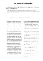
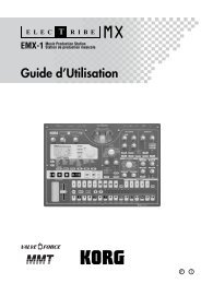
Here is the filter routings capabilities of<br />
the <strong>Virus</strong>.<br />
ACCESS VIRUS OS4 33<br />
Filter Routing
34 CHAPTER 4<br />
Introduction<br />
THE FIRST OSCILLATOR<br />
To this point, we have turned our<br />
attention exclusively to soundshaping<br />
functions and have always<br />
started with the same basic material:<br />
a so-called sawtooth wave.<br />
This waveshape is especially wellsuited<br />
as a neutral starting point<br />
as it contains all of the so-called<br />
natural scale of overtones, which<br />
give the filter plenty of quality<br />
material to work with.<br />
The filters, with the exception of a<br />
notch filter or band stop (BS), trim<br />
the far reaches of the tonal spectrum,<br />
so for instance a signal<br />
sounds muddier after it has been<br />
routed through a low pass filter.<br />
You can well imagine that this type<br />
of sound modification is substantial<br />
but insufficient for shaping<br />
more subtle differences in tone.<br />
For instance the tone of a trumpet<br />
differs significantly from that of a<br />
saxophone even though no one<br />
would seriously claim that either<br />
of the instruments has a muddier<br />
tone than the other.<br />
What you need is a sound-shaping<br />
option for the portion of a signal<br />
that a filter allows to pass. And of<br />
course you also need a tool for<br />
determining the pitch of a signal.<br />
In synthesizers, both of these tasks<br />
are executed by oscillators. They<br />
oscillate at a variable pitch that<br />
can be modulated and they also<br />
generate different waveshapes<br />
which give the filters a wider variety<br />
of material to work with.<br />
The <strong>Virus</strong> is equipped with two<br />
main oscillators and a so-called<br />
suboscillator. We will first take a<br />
look at Oscillator 1, which is the<br />
oscillator you have already heard<br />
in action during your experiments<br />
thus far.<br />
Dial in the same basic sound that<br />
you started with at the very beginning.<br />
Now modify the amplifier<br />
envelope so you are working with<br />
a less grating sound, but hold back<br />
on any other filter or saturation<br />
modifications so you can hear the<br />
purest oscillator signal possible.<br />
Locate the section labeled “1”, it is<br />
bordered off in a separate area at<br />
the far left of the section labeled<br />
OSCILLATORS. No check out the two
ACCESS VIRUS OS4 35<br />
The First Oscillator<br />
pots labeled SHAPE and WAVE SEL/<br />
PW. These enable you determine<br />
the waveshape and consequently<br />
the tonal spectrum of Oscillator 1.<br />
In the sound program, SHAPE is<br />
preset to the center position (12<br />
o’clock), which is equivalent to a<br />
value of 64. On the pot, this position<br />
is identified via a graphic<br />
depiction of a sawtooth wave. You<br />
can definitely see why this waveshape<br />
bears the name “sawtooth.”<br />
Press and hold a key and slowly<br />
turn the pot clockwise. You should<br />
be able to hear how the tone<br />
becomes increasingly more hollow-sounding.<br />
You might say this<br />
effect thins the sound out, but in<br />
any case, the entire tonal spectrum<br />
is affected by an equal measure,<br />
which is an audio result filters are<br />
unable to achieve.<br />
The waveshape that is audible<br />
when you turn the SHAPE pot to<br />
the far right is a so-called pulse<br />
wave. The graphical representation<br />
of this waveshape on the control<br />
panel gives you a good idea of its<br />
appearance. It is unique because<br />
the duration of the negative pulse<br />
is equal to the duration of the positive<br />
pulse: It has a so-called pulse<br />
width of 50%. The tone of a pulse<br />
wave is different to that of a sawtooth<br />
wave because it does not<br />
contain all overtones in the natural<br />
overtone scale, only the odd-numbered<br />
tones, i.e. the first (the root<br />
note that determines the pitch),<br />
third, fifth, and so forth. By turning<br />
the SHAPE pot from the sawtooth<br />
control range towards the pulse<br />
control range, you are actually dialing<br />
every other overtone out of the<br />
mix, which explains why the sound<br />
becomes thinner.
36 CHAPTER 4<br />
Introduction<br />
You can continue modifying the<br />
sound by reducing the symmetrical<br />
width of the pulse wave. In the<br />
<strong>Virus</strong>, you can execute this soundshaping<br />
measure via the WAVE<br />
SEL/PW (PW = pulse width) pot,<br />
PROVIDED THE SHAPE POT IS SET TO<br />
A POSITION IN THE RIGHT HALF OF<br />
ITS CONTROL RANGE (LATER THAN<br />
12 O’CLOCK). Rotate the WAVE SEL/<br />
PW pot slowly from the left to the<br />
right and leave the SHAPE pot at<br />
the far right position. You can hear<br />
how the treble content of the<br />
sound increases while the sound<br />
becomes ever thinner. At the far<br />
right position, the signal is no<br />
longer audible because the pulse<br />
width is equivalent to 0% and consequently<br />
the wave no longer<br />
oscillates.<br />
Starting at the center position (12<br />
o’clock) indicated by the sawtooth,<br />
turn the SHAPE pot counter-clockwise<br />
towards the left. You can hear<br />
how the overtones are increasingly<br />
mixed out of the signal until you<br />
can only hear the root note. This<br />
sound is produced by a so-called<br />
sine wave, one of 64 other waveshapes<br />
that you have at your disposal<br />
for sound generation<br />
purposes. These waveshapes can<br />
also be activated via WAVE SEL/PW<br />
(WAVE SEL: Wave Select), PRO-<br />
VIDED THE SHAPE POT IS SET TO A<br />
POSITION IN THE LEFT HALF OF ITS<br />
CONTROL RANGE (EARLIER THAN 12<br />
O’CLOCK). Regardless of the current<br />
SHAPE setting, you can also<br />
select a wave in the EDIT menu<br />
under OSCILLATOR 1 WAVE.<br />
Go ahead and check out the different<br />
waveshapes. The second of the<br />
64 waves is a triangle wave, the<br />
remainder of the waveshapes are<br />
each a unique tonal blend. After<br />
you have familiarized yourself with<br />
this raw material, experiment with<br />
the parameters of the FILTERS and<br />
AMPLIFIER sections you have dealt<br />
with thus far (don’t forget about<br />
SATURATION and the corresponding<br />
function of the OSC VOL pot),<br />
to get a feel for how the diverse<br />
waveshapes respond to filtering,<br />
saturation and amplifier modifications.
ACCESS VIRUS OS4 37<br />
The Second Oscillator<br />
THE SECOND OSCILLA-<br />
TOR<br />
As we mentioned previously, in<br />
addition to the other sound<br />
sources, the <strong>Virus</strong> is equipped with<br />
a second oscillator. Judging from<br />
the amount of control features on<br />
this oscillator’s section of the control<br />
panel, you have probably<br />
already gathered that it has more<br />
sound-shaping options than Oscillator<br />
1.<br />
Dial in the basic sound program<br />
that you had at the very beginning;<br />
change the amplifier envelope to<br />
suit your taste. In the sound program,<br />
the OSC BAL (Oscillator Balance)<br />
pot in the MIXER section is<br />
preset to the far left. In order to<br />
hear Oscillator 2 in action, rotate<br />
the OSC BAL (Oscillator Balance)<br />
pot in the MIXER section to the<br />
right. Towards the center position<br />
(12 o’clock) you will hear how the<br />
tone is modified and as you rotate<br />
the pot further to the right, how<br />
the intensity of this modification is<br />
reduced. This effect is known as<br />
the comb filtering effect. It occurs<br />
when two signals with the same<br />
frequency but different phase<br />
lengths are mixed. Press the same<br />
key on your keyboard several times<br />
with the OSC BAL set to the center<br />
position (12 o’clock). You should<br />
notice that each note has a slightly<br />
different tone. The oscillators are<br />
the source of this effect. The oscillators<br />
of the <strong>Virus</strong> oscillate freely,<br />
consequently every time you play a<br />
note, the phase constellation<br />
between the two oscillators is different.<br />
For now, leave the OSC BAL<br />
POT at the center position (12<br />
o’clock).<br />
You are already familiar with Oscillator<br />
1’s SHAPE and WAVE SEL/PW<br />
pots. These functions are identical<br />
for Oscillator 2, so we won’t go into<br />
detail on them again.
38 CHAPTER 4<br />
Introduction<br />
Locate the pot labeled DETUNE<br />
and slowly rotate it to the right<br />
from the far left position (which is<br />
preset in the sound program). You<br />
can hear the tone start to waver<br />
and as you turn the pot further to<br />
the right, how this vibrato effect<br />
increases until Oscillator 2 sounds<br />
distinctly out of tune with Oscillator<br />
1. This wavering or vibrato-type<br />
effect has a popular traditional in<br />
synthesizers. It is used to achieve<br />
chorus effects, create sounds reminiscent<br />
of stringed instruments/<br />
string sections or simply beef up<br />
the sound.<br />
The SEMITONE pot enables you to<br />
transpose Oscillator 2 by plus/<br />
minus four octaves in semitone<br />
steps while Oscillator 1 maintains<br />
the pitch. This feature is especially<br />
interesting when used in conjunction<br />
with two other oscillator functions:<br />
synchronization and<br />
frequency modulation.<br />
Locate and activate the SYNC button<br />
in the OSCILLATOR 2 section<br />
(the LED must illuminate). The synchronization<br />
function forces Oscillator<br />
2 to restart its wave cycle at<br />
the same time as Oscillator 1 waveshape<br />
starts its cycle. The initial<br />
effect of this measure is that the<br />
wavering tone that resulted from<br />
detuning and mixing the oscillator<br />
signals disappears.<br />
The SYNC effect really becomes<br />
interesting when you transpose<br />
Oscillator 2 upwards in comparison<br />
to Oscillator 1 via the SEMITONE<br />
pot. What happens is that the<br />
wave cycle of Oscillator 2 is interrupted<br />
as soon as Oscillator 1 starts<br />
its cycle. The pitch of the second<br />
oscillator no longer has the<br />
expected effect, instead it generates<br />
special tones, in some cases<br />
for lack of a better description<br />
“screaming” type effects.<br />
The other effect that benefits from<br />
manipulating the interval between<br />
the oscillators is frequency modulation<br />
(FM). It generates new tonal<br />
spectra in which the signal of the<br />
first oscillator controls the frequency<br />
of the second oscillator<br />
similar to the manner in which filters<br />
can be controlled via envelopes.<br />
And here too you have a pot<br />
which allows you to control the<br />
intensity of: FM AMOUNT. Basically,<br />
this effect is similar to a<br />
vibrato, although here you’re dealing<br />
with an extremely fast vibrato
ACCESS VIRUS OS4 39<br />
The MIXER Section<br />
featuring a frequency within the<br />
range of human hearing. This signal<br />
is not actually audible as a<br />
vibrato effect. Instead, you’ll hear a<br />
sound modulation, in some cases,<br />
a very drastic one at that. Choose<br />
the pure sine waveshape for Oscillator<br />
2. In conjunction with the<br />
sine wave, the frequency modulation<br />
generates very clear, in some<br />
cases bell-like, spectra.<br />
In the <strong>Virus</strong> you have the option of<br />
combining the two functions<br />
called oscillator synchronization<br />
(SYNC) and frequency modulation<br />
(FM AMOUNT, to generate new<br />
harmonic spectra. Switch SYNC on<br />
and experiment with the FM<br />
AMOUNT. Also try out different<br />
SEMITONE settings and the diverse<br />
waveshapes of Oscillator.<br />
The <strong>Virus</strong> is equipped with a third<br />
master oscillator that lets you create<br />
further oscillations and spectra.<br />
You can access the parameters<br />
of this oscillator, which are<br />
described in a later chapter, via the<br />
OSCILLATOR EDIT menu.<br />
THE MIXER SECTION<br />
You have already come across two<br />
parameters of the MIXER section:<br />
OSC BAL determines the mix ratio<br />
between Oscillators 1 and 2; in the<br />
left half of its control range, OSC<br />
VOL determines the master volume<br />
of the oscillator mix. In the<br />
right half of the control range from<br />
the center position to the far right,<br />
OSC VOL increases the saturation<br />
intensity when a SATURATION<br />
curve has been activated.<br />
Now we’ll take a closer look at the<br />
final control element, the SUB OSC<br />
pot: It controls the volume of the<br />
fourth oscillator, the so-called<br />
SubOscillator, which always operates<br />
an octave below Oscillator 1.<br />
The SubOscillator is mixed to the<br />
Oscillator 1 and 2 master mix signal<br />
as determined by the OSC BAL pot.<br />
The master volume of the composite<br />
mix is controlled by the OSC VOL<br />
pot. The only other parameter<br />
available for the SubOscillator is<br />
accessible via the OSCILLATOR EDIT<br />
menu where you have the option
40 CHAPTER 4<br />
Introduction<br />
of selecting a triangle or pulse<br />
waveshape (SUB OSCILLATOR WAVE<br />
SQUARE/TRIANGLE).<br />
Another voice-internal signal<br />
source of the <strong>Virus</strong> has no visible<br />
control features on the control<br />
panel: the Noise Generator. The<br />
dedicated sound parameters are<br />
its volume and coloration (NOISE<br />
Volume and Color in the OSCILLA-<br />
TOR EDIT menu). On the middle<br />
position of NOISE Color the Noise<br />
Generator produces white noise.<br />
Please keep in mind that the level<br />
of the Noise Generator is not subject<br />
to the master volume controlled<br />
by the OSC VOL pot. In other<br />
words, it is audible even when OSC<br />
VOL is set to zero.<br />
The VIRUS’ ring modulator is a new<br />
sound source. The output of the<br />
two oscillators is multiplied to create<br />
interesting sounds with rich<br />
enharmonic overtones. These overtones<br />
are highly dependent on the<br />
frequency coherence of both oscillators<br />
and it’s waveforms. The frequency<br />
coherence can be changed,<br />
for instance use the OSC2 SEMI-<br />
TONE parameter. To blend in the<br />
ring modulator use EDIT: RING-<br />
MODULATOR VOLUME (in OSCILLA-<br />
TOR EDIT Menu). If the<br />
RINGMODULATOR VOLUME is zero,<br />
the ring modulator is switched off.<br />
OSC VOL does not affect the ring<br />
modulator level (or indeed the<br />
noise volume). Therefore the original<br />
oscillator signal can be leveled<br />
independently of the ring modulator.<br />
Be sure to check out what the<br />
ring modulator does when you<br />
select a sine wave for Oscillator 1<br />
and 2.
ACCESS VIRUS OS4 41<br />
The LFOs<br />
Now we can go on and solve the<br />
mysteries of the signal flow as<br />
determined by the FILTER ROUTING<br />
operating mode SPLIT: Here Oscillator<br />
1 and the SubOscillator are<br />
routed to Filter-1, whereas Oscillator<br />
2 and the Noise Generator are<br />
routed to Filter-2. Although the<br />
sound sources are split into two<br />
signal paths, you can still control<br />
the volume levels of the different<br />
elements as well as OSC VOL in the<br />
usual manner.<br />
THE LFOS<br />
When you first started this series<br />
of experiments with sounds, we<br />
promised that many of the functions<br />
the <strong>Virus</strong> can be “programmed”<br />
so that they are<br />
executed automatically. You have<br />
already learned how to control the<br />
volume and cutoff frequencies of<br />
both filters as well as the pitch and<br />
intensity of the frequency modulation<br />
of Oscillator 2 via “preprogrammed”<br />
envelopes. These<br />
options are great, but you have<br />
already encountered a number of<br />
functions where it would be a<br />
helpful if you could also program<br />
them to be executed automatically.<br />
And of course envelopes are<br />
great modulation sources, but you<br />
have to play a note every time you<br />
want to initiate an envelope. During<br />
your experiments you probably<br />
came across a function or two you<br />
would like to be able to control<br />
periodically - independently of<br />
notes. Some features that come to<br />
mind are traditional techniques<br />
such as vibrato (periodic pitch control)<br />
and tremolo (periodic volume
42 CHAPTER 4<br />
Introduction<br />
control). Another option you might<br />
like to have at your disposal is random<br />
parameter control.<br />
In the <strong>Virus</strong>, both of these tasks are<br />
executed by a so-called LFO (low<br />
frequency oscillator) that oscillates<br />
at frequencies below the audible<br />
range. An LFO is similar to the<br />
oscillators you have encountered<br />
thus far, but it oscillates significantly<br />
slower so that its output<br />
signal is too low for human hearing.<br />
So what good are they if you<br />
can’t hear them? LFOs are used in<br />
much the same manner as envelopes,<br />
with the major difference<br />
that the are repeated indefinitely.<br />
LFO 1<br />
Start with the usual basic sound<br />
configuration or chose a modified<br />
sound to suit your taste. Locate the<br />
RATE pot in the LFO 1 section of the<br />
control panel. The RATE pot is<br />
equipped with an LED that indicates<br />
the speed of the LFO as well<br />
as its waveshape. Turn the RATE<br />
pot and check out how the flash of<br />
the LED indicates the change of<br />
pace as you rotate the pot.<br />
Currently you are unable to hear<br />
the effect of the LFO as its modulation<br />
intensity is set to 0 in the<br />
sound program. In order to change<br />
this setting, you must access the<br />
AMOUNT button which works in<br />
conjunction with five vertically<br />
arrayed LEDs labeled OSC 1, OSC 2,<br />
PW 1+2, RESO 1+2 and ASSIGN:<br />
Press the AMOUNT button repeatedly<br />
and observe how the LEDs<br />
flash in succession (the LEDs OSC 1<br />
and OSC 2 flash separately as well<br />
as in unison). The corresponding<br />
modulation targets appear in the<br />
display, along with the modulation<br />
intensity values as determined by<br />
the VALUE pot and VALUE buttons.<br />
(You can also scroll through the
ACCESS VIRUS OS4 43<br />
The LFOs<br />
modulation targets via the<br />
PARAMETER button after you have<br />
pressed the AMOUNT button<br />
once.) Once you have dialed in a<br />
value other than 0 for a modulation<br />
target, the corresponding LED<br />
illuminates continually. This feature<br />
tells you at a glance that a<br />
modulation is underway even<br />
when the display indicates some<br />
other type of operation.<br />
Here are the definitions for<br />
the modulation targets:<br />
OSC-1 refers to the frequency of<br />
oscillator 1<br />
OSC-2 refers to the frequency of<br />
oscillator 2<br />
PW 1+2 means that the pulse<br />
widths of both oscillators are controlled<br />
in unison<br />
RESO 1+2 refers to the resonances<br />
of both filters. Please keep in mind<br />
that although each set of these<br />
parameters is assigned a common<br />
modulation intensity, you can still<br />
dial in different sound-shaping settings<br />
manually. In other words, the<br />
audible result of a joint modulation<br />
varies according to the values<br />
you have determined for the other<br />
parameters.<br />
ASSIGN Here you can freely select<br />
any modulation destination.<br />
Modulate the five parameters separately<br />
and in combinations with<br />
different intensities. Try to anticipate<br />
the sound you will come up<br />
with when you modulate the first<br />
oscillator, the second oscillator or<br />
both oscillators at once and see if<br />
the results match your expectations.<br />
If you can fairly reliably predict<br />
the outcome of your soundshaping<br />
efforts, you should have a<br />
handle on the information discussed<br />
thus far and can use your<br />
knowledge to create specific<br />
sounds you have in mind.<br />
During the course of your experiments,<br />
it is entirely possible that<br />
you have generated modulations<br />
that have no effect whatsoever on
44 CHAPTER 4<br />
Introduction<br />
the sound, for instance if you modulate<br />
the frequency of Oscillator 2<br />
although it is dialed out of the<br />
oscillator mix. When you run into<br />
this type of problem, check out the<br />
signal routing, if any configurations<br />
conflict with each other and<br />
memorize the situation, problem<br />
and solution. If you make a habit<br />
out of this, you won’t panic when<br />
you run into similar situations;<br />
instead you’ll keep your cool, analyze<br />
the unexpected sound and fix<br />
the mix.<br />
You are currently using a triangle<br />
as the LFO waveshape. You<br />
shouldn’t have any problem associating<br />
the periodic up and down<br />
fluctuation of the target parameter<br />
with this waveshape. Now activate<br />
the other available<br />
waveshapes for LFO 1 and try to<br />
picture the respective waveshape<br />
and associate it with the results of<br />
the modulation.<br />
The third waveshape is a descending<br />
sawtooth wave. You can convert<br />
it into to an ascending<br />
sawtooth by simply dialing in the<br />
requisite negative modulation<br />
intensities (AMOUNT).<br />
In the WAVE setting, you have<br />
access to 64 LFO waveshapes.<br />
Select these in the display section<br />
using the VALUE buttons:<br />
S&H (Sample and Hold) is a structured<br />
random modulation. Here<br />
random modulation values are<br />
generated. The value is held until<br />
the next beat impulse, then it<br />
abruptly jumps to a new random<br />
value.<br />
S&G (Sample and Glide) is a continual<br />
random modulation. Here<br />
the random values glide seamlessly<br />
into one another, the rate of<br />
which is determined by random<br />
modulation of the RATE value.<br />
The following 62 waveshapes are<br />
identical to the oscillator section’s<br />
digital waves. These can be used to<br />
create interesting rhythmic effects.<br />
Continued your experiments with<br />
different LFO waveshapes. Note<br />
that after a while you no longer<br />
consciously hear minimal modulation<br />
intensities - depending on the<br />
waveshape and modulation target<br />
(e.g. S&G +1 on OSC 1 or 2). However<br />
they do pep up the sound of
ACCESS VIRUS OS4 45<br />
The LFOs<br />
lend it a certain vitality. The key to<br />
many great sounds are these types<br />
of minimal modulations.<br />
You may have gathered that the<br />
LFOs of the <strong>Virus</strong> are polyphonic:<br />
If several notes are played simultaneously,<br />
these are controlled by<br />
dedicated LFOs, each with a<br />
slightly varied rate. This effect livens<br />
up the sound of chords, especially<br />
when they are sustained. To<br />
enhance this effect, activate the<br />
LFO 1 KEY FOLLOW in the LFO-EDIT-<br />
Menu.<br />
This function enables you to control<br />
the rate of the LFOs via the<br />
pitch, or more accurately, via the<br />
MIDI note number, so that higher<br />
notes generate faster LFO rates. As<br />
result, when you press and hold<br />
several notes you will hear all kinds<br />
of substantially different periodic<br />
fluctuations.<br />
Finally, the LFOs can also be used<br />
as additional envelopes. The control<br />
feature for this effect is the<br />
ENV MODE button. When you<br />
press this button, two things<br />
occur: For one, the LFO no longer<br />
initiates its cycles periodically, but<br />
only once at and in sync with the<br />
start of a note, and for the other,<br />
the active range of the LFO is<br />
switched from bipolar (in both<br />
directions from the zero position)<br />
to unipolar (from zero in one direction<br />
only). Please note that this<br />
applies to the modulation target<br />
but not the modulation intensity.<br />
Here you can still determine a<br />
value in the entire bipolar range.<br />
This effect is especially prominent<br />
when used in conjunction with the<br />
sawtooth wave, which enables a<br />
fade-out type of effect (when you<br />
dial in a positive AMOUNT value)<br />
or a volume-swell type of effect<br />
(negative AMOUNT) for the available<br />
modulation targets. Using the<br />
LFO Curve parameter located in<br />
the LFO EDIT menu, you can have<br />
the ”ramp” rise or fall exponentially.<br />
If you choose a triangle for<br />
your waveshape, the device will<br />
generate an ascending phase<br />
(attack) and a descending phase<br />
(decay). LFO Curve also lets you<br />
determine the temporal relationship<br />
between attack and decay; in<br />
other words, their respective rates..<br />
Dial in the desired speed via the<br />
RATE pot.
46 CHAPTER 4<br />
Introduction<br />
You can also use S&H and S&G in<br />
ENV MODE to come up with some<br />
attractive results: S&H generates a<br />
single random value at the start of<br />
a note (in this case, the RATE pot<br />
has no effect); S&G works in the<br />
same manner although in this case<br />
the RATE value is crucial. It determines<br />
the amount of time it takes<br />
to glide from the previous to the<br />
new random value.<br />
LFO 2<br />
The design of the second LFO is<br />
essentially the same as the first, so<br />
we’ll spare you the repetition of<br />
details SHAPE 1 and 2 are available<br />
as a joint modulation target; the<br />
filter frequencies and the Panorama<br />
position can be manipulated<br />
individually. You may also<br />
freely select a parameter for your<br />
modulation destination.
ACCESS VIRUS OS4 47<br />
LFO 2<br />
Volume and Panorama Position<br />
You probably noticed that the<br />
many of the sound shaping<br />
options available in the <strong>Virus</strong> occasionally<br />
influence the volume level.<br />
For instance, an unfiltered sawtooth<br />
is naturally louder than a<br />
highly filtered sawtooth because<br />
whenever you blend a part of the<br />
frequency spectrum out of the<br />
mix, you are automatically reducing<br />
the overall volume of the signal.<br />
This is why the <strong>Virus</strong> is<br />
equipped with a programmable<br />
volume pot for each SINGLE PRO-<br />
GRAM. It enables you to balance<br />
out the volume levels of your<br />
sound programs.<br />
You have already dealt with the<br />
Panorama position as a modulation<br />
target of LFO 2. Here you can<br />
not only modulate it, but also<br />
determine settings manually. For<br />
this purpose, use the parameter<br />
PANORAMA which is also located<br />
in the OUTPUT section of the EDIT<br />
menu. Like many other parameters,<br />
Panorama is a starting point<br />
for modulations. For instance you<br />
can modulate the Panorama position<br />
via LFO 2 even if you have<br />
already set the Panorama to the<br />
far left position. In this case of<br />
course you will only hear the Panorama<br />
position shift to the right.<br />
Locate the parameter PATCH VOL-<br />
UME in the COMMON section of<br />
the EDIT menu.<br />
01111111111111111112<br />
1 COMMON<br />
PatchVolume 100≤<br />
61111111111111111154<br />
Its value is set to 100 so that you<br />
have a reserve or headroom of 27<br />
volume increments when you are<br />
dealing with highly filtered<br />
sounds.
48 CHAPTER 4<br />
Introduction<br />
VELOCITY<br />
Velocity is one of the preferred<br />
modulation sources of keyboard<br />
players: A light key attack generates<br />
a low velocity value for the<br />
given note, a heavy touch generates<br />
a high velocity value. In the<br />
<strong>Virus</strong> you have ten modulation targets<br />
available for Velocity. Locate<br />
the VELOCITY section in the EDIT<br />
menu.<br />
01111111111111111112<br />
1 VELOCITY<br />
Osc1Shape +0≤<br />
61111111111111111154<br />
RESONANCE 2<br />
VOLUME<br />
PANORAMA<br />
which you can manipulate independently<br />
of one another in the<br />
familiar bipolar control range.<br />
A light key attack generates a low<br />
velocity value for the given note, a<br />
heavy touch generates a high<br />
velocity value.<br />
There you will find the modulation<br />
intensities for:<br />
OSC 1 SHAPE<br />
OSC 2 SHAPE<br />
PULSE WIDTH<br />
FM AMOUNT<br />
FILT 1 ENV AMT<br />
FILT 2 ENV AMT<br />
RESONANCE 1
ACCESS VIRUS OS4 49<br />
Unison Mode<br />
UNISON MODE<br />
When we talked about the oscillators,<br />
we mentioned that by subtly<br />
detuning signals, you can beef up<br />
sounds and achieve string-like<br />
sounds. The <strong>Virus</strong> is equipped with<br />
features that allow you to take this<br />
type of tonal manipulation a step<br />
further. On of these is the so-called<br />
UNISON MODE. It enables you to<br />
initiate two or more voices for each<br />
note played, which in turn lets you<br />
detune many oscillators. UNISON<br />
MODE also offers the option of<br />
spreading the voices generated by<br />
one note in the stereo panorama<br />
and shifting the phases of their<br />
LFOs so that all types of periodic<br />
effects can be used to produce an<br />
even more exciting signal.<br />
it determines how ”fat” the sound<br />
will be. You can use the UNISON<br />
Detune parameter to determine to<br />
which extent the active voices are<br />
detuned. UNISON PanSpread distributes<br />
them uniformly across the<br />
stereo panorama, a process by<br />
which you can also determine the<br />
width of a sound’s stereo base.<br />
When you activate UNISON mode<br />
for a sound, it can still be played<br />
polyphonically. However, depending<br />
on the number of voices you’ve<br />
dialed in, its polyphony will of<br />
course be considerably reduced in<br />
UNISON mode. The most efficient<br />
and the standard setting is UNI-<br />
SON mode = Twin, where two<br />
voices are played for every note. In<br />
the ”OFF” position, one voice per<br />
note is played.<br />
Locate the parameter group UNI-<br />
SON in the EDIT menu.<br />
01111111111111111112<br />
1 UNISON<br />
Mode<br />
Twin≤<br />
61111111111111111154<br />
UNISON mode determines how<br />
many voices the <strong>Virus</strong> will use to<br />
render a played note. In a nutshell,
50 CHAPTER 4<br />
Introduction<br />
THE CHORUS/FLANGER<br />
EFFECT<br />
Another function that delivers<br />
great effects based on pitch fluctuation<br />
is the so-called chorus effect.<br />
Chorus actually consists of a brief<br />
delay (generally up to approx. 50<br />
ms) which is varied periodically. By<br />
modulating the delay, the delayed<br />
signal is slightly detuned to the<br />
input signal (the so-called Doppler<br />
effect). This inconsistency in pitch<br />
between the original and effects<br />
signal is the source of the chorus<br />
effect. Feedback in the delay line<br />
enhances this effect. The left signal<br />
side is automatically modulated<br />
in a different manner than<br />
the right, so a chorus effect is great<br />
for converting mono signals into<br />
stereo signals.<br />
If the delay is less than approx. 10<br />
milliseconds, than the effect is<br />
called flanging or a flanger effect<br />
rather than chorus. In this case<br />
feedback is even more significant<br />
because it generates resonances<br />
that can be modulated and is thus<br />
yet another source of radical sound<br />
effects. If you determine high feedback<br />
values, you can clearly hear<br />
how the two sides of the signal are<br />
modulated differently - in reverse<br />
phase - by the LFO.<br />
Locate the parameter group CHO-<br />
RUS in the EFFECTS menu.<br />
01111111111111111112<br />
1 CHORUS<br />
Dir/Eff<br />
OFF≤<br />
61111111111111111154<br />
CHORUS DIR/EFF determines the<br />
balance between the original signal<br />
and the processed signal. The<br />
parameters RATE and SHAPE control<br />
another LFO that was installed<br />
specifically for the chorus LFO.<br />
DELAY is used to set the delay time,<br />
DEPTH determines the modulation<br />
intensity, and FEEDBACK controls<br />
the feedback level. When you want<br />
to generate a flanger effect, the<br />
FEEDBACK parameter’s negative<br />
control range lets you dial in softer<br />
characteristics for the flanger.<br />
Please keep in mind that the Chorus<br />
section in the <strong>Virus</strong> is fully stereophonic:<br />
Stereo positions as well<br />
as panorama modulations and stereo<br />
spread values that you have<br />
dialed in elsewhere remain intact<br />
in the effects signal.
ACCESS VIRUS OS4 51<br />
The Delay Effect<br />
THE DELAY EFFECT<br />
A delay effect is traditionally used<br />
to generated an echo of the input<br />
signal. Locate the parameter group<br />
DELAY in the EDIT menu.<br />
01111111111111111112<br />
1 DELAY<br />
EffectSend 0≤<br />
61111111111111111154<br />
Here you fill find parameters that<br />
are virtually identical to the<br />
parameters of the CHORUS group.<br />
Do not allow yourself to be confused<br />
by the slightly different terminology:<br />
The delay time is set via<br />
the parameter entitled TIME<br />
(equivalent to DELAY in the CHO-<br />
RUS section); the other features<br />
are FEEDBACK with a dedicated<br />
LFO and the familiar parameters<br />
RATE, DEPTH and SHAPE.<br />
For the other, LENGTH enables you<br />
to create substantially longer delay<br />
times, for instance to achieve complete<br />
echoes (maximum of 693<br />
ms) that are fully audible. The LFO<br />
allows you to modulate the delay<br />
as you would the chorus to achieve<br />
similar detuning effects. A stereo<br />
effect is achieved via different<br />
modulations of the left and right<br />
sides of the signal.<br />
Only two functions in the Delay<br />
section are different to the Chorus<br />
section: For one, it features an<br />
EFFECT SEND instead of the balance<br />
parameter DIR/EFF. EFFECT<br />
SEND is especially significant in<br />
MULTI MODE, where several PARTs<br />
with different levels are patched<br />
through the same delay effect.
52 CHAPTER 4<br />
Introduction<br />
MORE TO COME<br />
We have come to the end of these<br />
detailed instructions for novices.<br />
We hope we were able to help you<br />
become a bit more familiar with<br />
your new synthesizer and gain<br />
some confidence in how to handle<br />
it. As we mentioned earlier, this is<br />
just an introduction and does not<br />
cover all the functions and features<br />
of the <strong>Virus</strong>, only the basic<br />
components and how they affect<br />
the sound of the <strong>Virus</strong>. You should<br />
now be able to come to terms with<br />
the in-depth look at the <strong>Virus</strong> in<br />
the following section.
Concept and Operation
54 CHAPTER 5<br />
Concept and Operation<br />
OPERATING MODES<br />
In the <strong>Virus</strong> you can select from<br />
two basic operating modes, SIN-<br />
GLE MODE and MULTI MODE.<br />
In SINGLE MODE, the <strong>Virus</strong> is able<br />
to generate a single sound program<br />
only. All 24 voices, all effects<br />
and most importantly, all control<br />
features (with the exception of the<br />
MULTI button) function in conjunction<br />
with this one sound program.<br />
You might say a SINGLE program is<br />
a combination of all functions and<br />
effects that determine the sound<br />
of the <strong>Virus</strong>. In other words: A SIN-<br />
GLE program is a ”sound” of the<br />
<strong>Virus</strong>, that can be stored and<br />
recalled.<br />
The <strong>Virus</strong> provides access to 512<br />
SINGLE sounds. Next to the 256<br />
RAM sounds (Bank A and Bank B),<br />
you have two banks available with<br />
a total of 256 factory sounds. These<br />
banks, C and D, are stored in the<br />
FLASH ROM and can not be overwritten<br />
via STORE.<br />
The MIDI receive channel in SIN-<br />
GLE MODE is the Global Channel.<br />
You can change the Global Channel<br />
in the CTRL menu.<br />
In MULTI MODE, the <strong>Virus</strong> can combine<br />
up to sixteen (SINGLE) sound<br />
programs, among which the maximum<br />
available number of 24<br />
voices are allocated dynamically.<br />
All simultaneously available<br />
sounds can be manipulated in realtime;<br />
for this purpose the control<br />
panel enables you to switch<br />
among the sixteen so-called<br />
PARTS.<br />
In MULTI MODE, the actual sound<br />
parameters are augmented with<br />
other functions that deal with how<br />
the involved SINGLE programs are<br />
structured or organized. These<br />
include the volume levels of the<br />
single programs, their MIDI channels,<br />
output assignments, etc.<br />
On the <strong>Virus</strong>, we differentiated<br />
fundamentally between SINGLE<br />
mode and MULTI mode. This distinction<br />
is reflected in the contents<br />
of the menus: If the LED on the<br />
SINGLE button lights up, the CTRL<br />
and EDIT menus let you access the<br />
sound parameters of the current
ACCESS VIRUS OS4 55<br />
The Multi-Single Mode<br />
SINGLE program. If the LED on the<br />
MULTI button lights up, the CTRL<br />
and EDIT menus will contain the<br />
appropriate ”administrative”<br />
parameters for the current MULTI<br />
program. For example, here you<br />
have the option of selecting the<br />
SINGLE program for each of the 16<br />
MULTI PARTs.<br />
THE MULTI-SINGLE<br />
MODE<br />
In MULTI mode, the EDIT and CTRL<br />
menus are responsible for administering<br />
the 16 PARTs. Consequently,<br />
you can’t access SINGLE<br />
program parameters directly here.<br />
Beyond that, you’re unable to<br />
change the SINGLE programs<br />
directly here, which would admittedly<br />
be a handy option when<br />
you’re working with a sequencer.<br />
This is why the <strong>Virus</strong> features<br />
MULTI SINGLE mode, which,<br />
strictly speaking, is more an alternative<br />
view of MULTI mode rather<br />
than a further mode in its own<br />
right.<br />
Activate MULTI SINGLE mode by<br />
pressing the MULTI and SINGLE<br />
buttons simultaneously. The name<br />
of the selected MULTI program will<br />
disappear and instead you’ll see<br />
the name of the SINGLE program<br />
for the selected PART. Now you can<br />
page or scroll through the 16 PARTs<br />
using the PART buttons and select<br />
a SINGLE program for every channel.<br />
You can process the currently<br />
selected PART or, more accurately,<br />
edit its sound, using the control
56 CHAPTER 5<br />
Concept and Operation<br />
features. The CTRL and EDIT menus<br />
let you access the usual SINGLE<br />
parameters. In this operating<br />
mode, you’ll find that the CTRL<br />
menu has been expanded to<br />
include some organizational<br />
parameters, for instance, the<br />
PART’s volume level, panorama and<br />
output assignments. You’ll always<br />
see the number of the selected<br />
PART on the upper left in the display.<br />
The PART buttons don’t actually<br />
change sounds, they simply set<br />
the user interface of the <strong>Virus</strong> to<br />
the desired PART. Irrespective of<br />
the given setting, all PARTs can be<br />
controlled simultaneously via<br />
MIDI. Consequently, MULTI SINGLE<br />
mode, which makes handling so<br />
much easier, is the ideal choice<br />
when you’re working with a connected<br />
sequencer.<br />
Please bear in mind that MULTI<br />
SINGLE mode is really just another<br />
view of the normal MULTI mode.<br />
MULTI SINGLE mode doesn’t offer a<br />
unique data type for storing<br />
sounds, it always works with the<br />
MULTI program currently selected<br />
in normal MULTI mode. All of the<br />
normal MULTI mode parameters<br />
(keyboard zones, etc.) remain<br />
intact and in force even though<br />
you can’t view or vary them in<br />
MULTI SINGLE mode. You can set<br />
the device to normal MULTI mode<br />
at any time by pressing the MULTI<br />
button. To return to the MULTI SIN-<br />
GLE mode view, simply press the<br />
MULTI and SINGLE buttons simultaneously.<br />
When you’re working with a<br />
sequencer, start with a MULTI program<br />
that features neutral settings<br />
for its ”administrative”<br />
parameters, for example, the<br />
MULTI program M0 Sequencer.<br />
Here the PART numbers are identical<br />
to the MIDI channels of the<br />
PARTs. Now when you work in<br />
MULTI SINGLE mode, the <strong>Virus</strong><br />
responds as if it were in SINGLE<br />
mode, except that you have 16<br />
sounds available simultaneously<br />
on 16 MIDI channels. Use the PART<br />
buttons to select these sounds.<br />
You only need to exit MULTI SIN-<br />
GLE mode when you want to store<br />
the MULTI program, for example,<br />
to save the current global delay/<br />
reverb setting. In MULTI mode,<br />
these settings are not stored along<br />
with SINGLE sounds.
ACCESS VIRUS OS4 57<br />
Edit Buffers<br />
In addition, you can activate<br />
another complete MULTI program<br />
in MULTI mode only.<br />
EDIT BUFFERS<br />
Whenever you play or edit a SIN-<br />
GLE program, its current data is<br />
stored in an edit buffer. This is an<br />
individual memory slot for SINGLE<br />
programs that has nothing to do<br />
with the memory slots in the<br />
sound banks. When you activate a<br />
new SINGLE, its data is copied to<br />
the edit buffer. There you can edit<br />
it as you see fit while the original<br />
remains unchanged in the bank.<br />
When you activate STORE (more on<br />
this in a bit), the content of the<br />
edit buffer is copied back to the<br />
original slot in the bank (or, if you<br />
so desire, to another memory slot).<br />
In MULTI mode, you have one<br />
MULTI edit buffer and 16 SINGLE<br />
edit buffers for the PARTs at your<br />
disposal. When you activate<br />
another a MULTI program, its data<br />
is copied from the MULTI bank to<br />
the MULTI edit buffer. The MULTI<br />
program in turn contains address<br />
information for the SINGLEs<br />
involved, in other words, the bank<br />
and program numbers. These<br />
addresses are also copied from the<br />
SINGLE banks into the 16 SINGLE<br />
edit buffers for the PARTs.
58 CHAPTER 5<br />
Concept and Operation<br />
When you store a MULTI program,<br />
only the addresses of the SINGLE<br />
programs’ original slots are saved,<br />
but not, however, the sound data<br />
in the 16 SINGLE edit buffers. These<br />
must be stored separately in the<br />
SINGLE program banks.<br />
This type of edit buffer is used in<br />
most synthesizers; its advantages<br />
are many:<br />
It lets you edit copies of sounds<br />
without sacrificing the original<br />
sounds.<br />
Edit buffers can be stored in a<br />
sequencer and sent from it to the<br />
<strong>Virus</strong> independently of the sounds<br />
stored in the device (see “DUMP:<br />
The Sound in the Song” on<br />
page 222).<br />
In MULTI-Mode (or MULTI-SIN-<br />
GLE-Mode) the same SINGLE-program<br />
can be recalled and edited on<br />
different parts. In this case all<br />
involved EDIT-buffers contain variations<br />
of the same original sound.
Handling
60 CHAPTER 6<br />
Handling<br />
PARAMETER SELEC-<br />
TION AND DATA ENTRY<br />
In the <strong>Virus</strong>, we distinguished<br />
between two types of parameters.<br />
On the one hand, it features<br />
parameters that are essential in<br />
generating or synthesizing sounds,<br />
on the other hand it has sound<br />
parameters and organizational<br />
parameters that are more of a<br />
peripheral nature. This distinction<br />
is apparent in handling and operation<br />
of the <strong>Virus</strong>: All essential<br />
sound parameters feature a dedicated<br />
knob or button so that you<br />
can access these directly - especially<br />
while you are playing!. In just<br />
a few cases (where appropriate or<br />
where it facilitates better handling),<br />
the control features have<br />
dual functions.<br />
Peripheral parameters, on the<br />
other hand, are compiled in<br />
menus. Among these menus are<br />
above all the EDIT, the CTRL (short<br />
for ”Control” and the EFFECTS<br />
menu as well as the four local EDIT<br />
menus in the individual function<br />
blocks. The EDIT menus contain<br />
parameters that you will require<br />
less frequently, but some of these<br />
are nonetheless indispensable for<br />
programming sounds. The local<br />
EDIT menus are there for a purpose<br />
– to help you distinguish clearly<br />
between the various parameters.<br />
Here you’ll find parameters that<br />
affect directly the given functional<br />
section, but are not equipped with<br />
dedicated control features.<br />
Irrespective of which operating<br />
mode you may have activated, the<br />
EDIT menu contains the sound<br />
parameters of the selected SINGLE<br />
program (in SINGLE mode and<br />
MULTI SINGLE mode) or organizational<br />
parameters for MULTI mode.<br />
In SINGLE mode and MULTI SINGLE<br />
mode, the CTRL menu contains further<br />
SINGLE parameters such as<br />
the arpeggiator, etc.<br />
In the CTRL menu, you’ll also find –<br />
irrespective of the given operating<br />
mode – a number of global parameters.<br />
These are called MIDI, SYS-
ACCESS VIRUS OS4 61<br />
Parameter Selection and Data Entry<br />
TEM and so forth and are not<br />
stored with a SINGLE or a MULTI<br />
program.<br />
Located next to some of these<br />
parameters, you’ll see the abbreviations<br />
”ENA” and ”DIS”. The option<br />
ENA means enable and DIS means<br />
disable.<br />
Call up a menu by simply pressing<br />
the corresponding button. Once<br />
you have opened the menu and it<br />
appears in the display, you can<br />
scroll through its parameters one<br />
after another using the PARAME-<br />
TER buttons and edit them using<br />
the VALUE buttons and knobs.<br />
you are holding down. This handy<br />
feature lets you swiftly go from<br />
one parameter type to another, for<br />
instance, from all chorus-related to<br />
all delay-related parameters. If you<br />
also hold the second parameter<br />
button down, the menus will automatically<br />
scroll in the selected<br />
direction. Once you’ve scrolled to<br />
the desired parameter group, simply<br />
select the desired parameter by<br />
pressing the button briefly. You can<br />
also step through the parameters<br />
by repeatedly pressing the same<br />
menu button.<br />
If you press the PARAMETER buttons<br />
briefly, you can scroll through<br />
the parameters contained in any<br />
given menu step by step in the<br />
desired direction. If you press and<br />
hold one of the parameter buttons<br />
for a bit longer, the display will<br />
automatically scroll through the<br />
list of parameters in the given<br />
menu. When you press and hold<br />
one PARAMETER button and then<br />
press the other PARAMETER button,<br />
the display will scroll through<br />
the menu in parameter groups in<br />
the direction of the button that
62 CHAPTER 6<br />
Handling<br />
The menus, particularly the<br />
EFFECTS menu, contain parameter<br />
groups that are related by virtue of<br />
their function, for instance, all<br />
parameters that are used to control<br />
the phaser. When you switch<br />
the phaser off (PHASER Dry/Eff =<br />
OFF), all Phaser parameters are of<br />
course irrelevant and will no longer<br />
appear in the menu. In other<br />
words, when the phaser is disabled,<br />
you can’t view its parameters.<br />
The reason for this is to make<br />
menus clearer and less cluttered.<br />
The VALUE +/- buttons let you<br />
change the value of a parameter in<br />
steps. When you hold one of these<br />
buttons down, the value changes<br />
automatically and the longer you<br />
hold the button, the faster the<br />
pace of the value change. You can<br />
increase this pace even further by<br />
pressing and holding one VALUE<br />
button and simultaneously pressing<br />
the other VALUE button. If you<br />
press and release both VALUE buttons<br />
simultaneously, the parameter<br />
is set to its default value<br />
(mostly zero). This pertains to unipolar<br />
parameters (value range of 0<br />
to 127) as well as bipolar parameters<br />
(value range of -64 to +63).<br />
You can also use the VALUE knob to<br />
change the value of the selected<br />
parameter. The VALUE knob<br />
responds to the KNOB MODE settings<br />
as described in the paragraph<br />
below.<br />
The triangular icon located next to<br />
the parameter value indicates in<br />
which direction you have to<br />
change a value if you would like to<br />
reset the parameter to the value<br />
that has been stored to date. The<br />
previously stored parameter value<br />
as well as the current value are displayed<br />
for parameters that feature<br />
a dedicated knob.
ACCESS VIRUS OS4 63<br />
Knob Modes<br />
KNOB MODES<br />
For all knobs with the exception of<br />
MASTER VOLUME, you can select<br />
from four operating modes in the<br />
CTRL menu. These are located<br />
under the menu item KNOB<br />
MODE:<br />
OFF The knobs are inactive.<br />
JUMP In Jump Mode, the<br />
parameter jumps directly and<br />
absolutely to the value determined<br />
by the current position of the knob.<br />
SNAP When you adjust a knob<br />
In Snap Mode, the original setting<br />
determines the value until the<br />
point where the movement of the<br />
knob passes beyond this position.<br />
In other words, the parameter does<br />
not jump to the value as in JUMP<br />
Mode. However, keep in mind that<br />
your adjustments have no effect<br />
on the parameter until the knob<br />
“snaps” on at the position equivalent<br />
to the original value. In SNAP<br />
mode, an ®-symbol appears to the<br />
right of the number. It indicates in<br />
which direction the VALUE knob<br />
must be turned to exceed the current<br />
parameter value.<br />
RELATIVE When you adjust a<br />
knob in RELATIVE Mode, the<br />
parameter is affected immediately<br />
but not absolutely. In other words,<br />
the value change from the original<br />
value to the value reflects precisely<br />
the amount you adjusted via a<br />
given control. Generally this operating<br />
mode allows you to adjust a<br />
parameter immediately, without<br />
radical jumps. However, the down<br />
side is that in an unfavorable configuration<br />
- the worst-case scenario<br />
being a maximum parameter<br />
value and a knob position at the<br />
minimum value - you do not have
64 CHAPTER 6<br />
Handling<br />
the full control range of the knob<br />
at your disposal. To counteract this<br />
situation, you have to turn the<br />
knob in the opposite direction to<br />
adjust the physical knob position<br />
so that it is equivalent to the<br />
actual parameter value. In RELA-<br />
TIVE Mode, the triangle to the<br />
right of the number indicates if the<br />
VALUE knob coincides with the<br />
parameter value (≤) or not (Ω).<br />
01111111111111111112<br />
1 SYSTEM<br />
KnobMode<br />
Jump≤<br />
61111111111111111154<br />
DISPLAY OF VALUES<br />
When a menu is active, different<br />
display options are available for<br />
parameters with a dedicated knob.<br />
These can be selected under the<br />
menu item KNOB DISPLAY in the<br />
CTRL menu:<br />
OFF Knob movements are not<br />
displayed; the current contents of<br />
the display remain intact when<br />
you turn a knob.<br />
ON The lower row of the display<br />
is being overwritten by the<br />
parameter's value.<br />
SHORT When you turn a knob,<br />
the current contents of the lower<br />
display line are briefly overwritten<br />
by data representing the change in<br />
parameter value; once the action is<br />
completed, the original contents<br />
reappear in the lower display line.<br />
LONG Same as SHORT, except<br />
that - you guessed it - the display<br />
shows the knob data for a longer<br />
period of time.
ACCESS VIRUS OS4 65<br />
Display of values<br />
ON The contents of the display<br />
are overwritten when you turn a<br />
knob; the original menu does not<br />
reappear in the display.<br />
01111111111111111112<br />
1 SYSTEM<br />
KnobDispl Short≤<br />
61111111111111111154
66 CHAPTER 6<br />
Handling
All about the memory
68 CHAPTER 7<br />
All about the memory<br />
STORE<br />
The mode structure of SINGLE,<br />
MULTI and MULTI SINGLE MODE is<br />
mirrored in the STORE functions: In<br />
SINGLE MODE, STORE saves the<br />
current SINGLE PROGRAM; in<br />
MULTI MODE, STORE saves the current<br />
MULTI PROGRAM; and in<br />
MULTI SINGLE MODE, the SINGLE<br />
PROGRAM of the current PART is<br />
stored.<br />
The STORE process is always the<br />
same regardless of the operating<br />
mode: Press STORE. You then gain<br />
access to the STORE menu. There<br />
you can use the PARAMETER buttons<br />
to move among the individual<br />
letters in the lower name entry<br />
line and the number of the destined<br />
memory location as well as<br />
the bank number in the upper line.<br />
Use the VALUE button to make<br />
entries. The term in the upper display<br />
line indicates the name of the<br />
memory location which you will<br />
overwrite when you store the program.<br />
Once all of the entries correspond<br />
to the data you have in mind, press<br />
STORE again to conclude the process<br />
and return to the previously<br />
active operating mode of the <strong>Virus</strong>.<br />
If for whatever reason you change<br />
your mind and want to cancel the<br />
operation, simply press SINGLE or<br />
MULTI to return to the previous<br />
operating mode without storing<br />
the program.<br />
To belabor the point, when you<br />
store a MULTI program, only the<br />
content of the MULTI edit buffer is<br />
saved, not however the sound programs<br />
in the PARTs. These must be<br />
stored individually in MULTI SINGLE<br />
mode.
ACCESS VIRUS OS4 69<br />
Compare<br />
If you want to store the SINGLE<br />
programs in the PARTs to their<br />
original slots in the SINGLE banks<br />
all at the same time, simply press<br />
STORE and 1 C126 - Init<br />
01111111111111111112<br />
1 C126 - Init<br />
[STORE] TO...<br />
61111111111111111154<br />
COMPARE<br />
sound and, at the same time, hear<br />
the sound that you will overwrite.<br />
The edited sound is not modified<br />
or overwritten during this process.<br />
Press STORE to do just that to the<br />
edited sound – store it. Press<br />
MULTI or SINGLE to quit the STORE<br />
process and/or exit Compare<br />
mode.<br />
01111111111111111112<br />
1 C126 -Init -<br />
compare<br />
61111111111111111154<br />
When you press STORE and then<br />
EDIT or CTRL, you will activate<br />
Compare mode. After you have<br />
programmed or edited a SINGLE<br />
sound, Compare mode lets you<br />
hear the unedited sound that was<br />
originally stored in this memory<br />
slot. Press EDIT or CTRL repeatedly<br />
to switch back and forth between<br />
the Compare sound and the edited<br />
sound so that you can - surprise,<br />
surprise – compare the two<br />
sounds. Use the PARAMETER/BANK<br />
buttons and the VALUE buttons to<br />
step through the bank and program<br />
numbers of the Compare<br />
sound. This lets you search for a<br />
new memory slot for the edited
70 CHAPTER 7<br />
All about the memory
Master Clock and Midi-Clock
72 CHAPTER 8<br />
Master Clock and Midi-Clock<br />
MASTER CLOCK AND<br />
MIDI-CLOCK<br />
The <strong>Virus</strong> is equipped with a global<br />
clock generator that lets you sync<br />
the LFOs, arpeggiators and delay<br />
up to a common song tempo and<br />
rhythm. The clock generator works<br />
either internally with a freely variable<br />
speed or it can, in turn, by<br />
synced up to the MIDI clock of an<br />
external sequencer. This synchronization<br />
occurs automatically when<br />
the device receives a MIDI clock<br />
signal via its MIDI In. You can vary<br />
the speed of the clock generator<br />
within a range of 63 to 190 BPM<br />
(beats per minute) via CLOCK<br />
TEMPO. When the device is synchronized<br />
via MIDI clock, the clock<br />
generator automatically accepts<br />
the speed dictated by the connected<br />
sequencer; the internal<br />
tempo setting is in this case meaningless<br />
and thus disabled. The individual<br />
sections of the <strong>Virus</strong> are<br />
synced up to the clock generator at<br />
rhythmic intervals such as 1/16, 1/4<br />
and so forth. These values may be<br />
assigned individually for every section.<br />
(ARPEGGIATOR CLOCK, CLOCK<br />
LFO 1, CLOCK LFO 2, CLOCK LFO 3,<br />
DELAY CLOCK, see the respective<br />
sections).<br />
In SINGLE MODE, CLOCK TEMPO<br />
pertains to the current SINGLE<br />
PROGRAM and is stored along with<br />
it. In MULTI MODE, the CLOCK<br />
TEMPO settings for the involved<br />
SINGLE PROGRAMs are ignored.<br />
Instead, all involved SINGLE PRO-<br />
GRAMs are controlled via the same<br />
clock generator. Its CLOCK TEMPO<br />
is saved in the MULTI PROGRAM (as<br />
are the settings for the global<br />
delay effect).
ACCESS VIRUS OS4 73<br />
Master Clock and Midi-Clock<br />
This feature lets you control the<br />
LFOs and arpeggiators of several<br />
MULTI PARTS in a common rhythmic<br />
context.<br />
A small will appear in the display<br />
when the <strong>Virus</strong> is receiving<br />
MIDI Clock data. If you’re sure you<br />
do NOT want the device to be synchronized<br />
automatically to MIDI<br />
clock, set MIDI CLOCK RX to Off (in<br />
the CTRL menu).) To avoid confusion,<br />
please keep in mind that MIDI<br />
Clock is not the same thing as MIDI<br />
Time Code. The latter doesn’t deal<br />
with tempo at all but with timerelated<br />
information structured in<br />
hours, minutes, seconds, etc. which<br />
is of no benefit to you in this context.
74 CHAPTER 8<br />
Master Clock and Midi-Clock
The Modulation Matrix and Definable Knob
76 CHAPTER 9<br />
The Modulation Matrix and Definable Knob<br />
CREATING MODULA-<br />
TION CONFIGURA-<br />
TIONS VIA ASSIGN<br />
As a rule, it is of course desirable to<br />
be able to create modulation routing<br />
configurations on a synthesizer.<br />
In other words, you want to<br />
enjoy the freedom to combine different<br />
modulation sources and<br />
destinations as you see fit. Sometimes<br />
you may come up with ideas<br />
for standard modulations that the<br />
”hard-wired” factory modulation<br />
routing options simply can’t satisfy.<br />
This is why we opted to equip<br />
the <strong>Virus</strong> with a versatile Modulation<br />
Matrix – you’re sure to find it a<br />
welcome addition. On the <strong>Virus</strong>,<br />
you can create modulation routing<br />
configurations freely as you see fit<br />
using ASSIGN options. They are<br />
located in the EDIT menu, where<br />
they appear under the name of –<br />
you guessed it – ASSIGN).<br />
The three ASSIGN options let you<br />
control up to six modulation destinations<br />
via up to three modulation<br />
sources. Simply go to ASSIGN,<br />
select one of the modulation<br />
sources (SOURCE) and one or several<br />
modulation destinations (DES-<br />
TINATION). Each of these<br />
configurations features a parameter<br />
that determines modulation<br />
intensity (AMOUNT). ASSIGN 1 can<br />
control one modulation destination,<br />
ASSIGN 2 can control two and<br />
ASSIGN 3 can control three modulation<br />
destinations, each with<br />
independent AMOUNTs.<br />
These ASSIGN options serve several<br />
purposes: for one, they let you<br />
assign an external MIDI controller,<br />
for example, the keyboard’s modulation<br />
wheel, to the desired parameter.<br />
You can also chose to use the<br />
sound generator’s internal modulators,<br />
such as LFOs and envelopes,<br />
as modulation sources. The control<br />
range of the source may be limited<br />
via the AMOUNT values or inverted<br />
so that the modulation occurs<br />
strictly within the desired value<br />
range for the target parameter. For<br />
your target parameters, you can<br />
chose from among virtually all<br />
sound parameters that feature an<br />
infinitely variable control range –<br />
ergo, you have more than 100<br />
modulation destinations at your<br />
disposal! Since the sources and<br />
destinations may be selected independently,<br />
you may even modulate
ACCESS VIRUS OS4 77<br />
Creating Modulation Configurations via Assign<br />
a single parameter by using up to<br />
three modulation sources simultaneously.<br />
For this purpose, the control<br />
signals of the modulation<br />
sources are added up or overlapped.<br />
Conversely, you can also<br />
modulate up to six parameters<br />
with just one controller, which<br />
gives you all kinds of sophisticated<br />
sound morphing options. For this<br />
purpose, select the same source<br />
for all three ASSIGN options so<br />
that it modulates all six possible<br />
destinations. This lets you radically<br />
reshape sounds and even<br />
transform or morph them into<br />
entirely different sounds.<br />
modulation source, i.e. the respective<br />
LFO, is a fixed default that you<br />
can’t change.<br />
01111111111111111112<br />
1 ASSIGN<br />
Source<br />
OFF≤<br />
61111111111111111154<br />
You’ll find a list of available<br />
sources and DESTINATIONS in the<br />
appendix. (see “Appendix” on<br />
page 251).<br />
In addition to the three ASSIGN<br />
options, the user interface features<br />
– as discussed earlier – a modulation<br />
destination for LFO 1 and 2<br />
called ASSIGN. Here the same principle<br />
applies: you can select a modulation<br />
destination and vary<br />
modulation intensity as you see fit.<br />
The only difference here is that the
78 CHAPTER 9<br />
The Modulation Matrix and Definable Knob<br />
THE DEFINABLE KNOBS<br />
The <strong>Virus</strong> is equipped with two<br />
knobs that, rather than being dedicated<br />
to predefined tasks, may be<br />
assigned to different parameters<br />
by you, the user. This option is<br />
quite handy, for it lets you control<br />
directly the many menu parameters<br />
that do not feature a dedicated<br />
knob.<br />
These DEFINABLE knobs operate in<br />
three different modes:<br />
GLOBAL The knob controls the<br />
parameter that you have set to<br />
Global in the DEFINABLE menu<br />
regardless of what the other settings<br />
and the selected SINGLE program<br />
may be.<br />
SINGLE The knob controls the<br />
parameter that you have set to<br />
Single in the DEFINABLE menu. The<br />
setting for this parameter is stored<br />
in the SINGLE program and called<br />
up whenever you select this program.<br />
If, however, you have not<br />
selected a parameter for this program<br />
(DEFINABLE Single = OFF),<br />
the setting for DEFINABLE Global is<br />
automatically enabled.<br />
MIDICONTRL Here the controller<br />
number entered in the DEFIN-<br />
ABLE MIDI menu is sent regardless<br />
of what the other settings and the<br />
selected SINGLE program may be.<br />
Comparable to a small MIDI fader<br />
box, this mode is used to control<br />
connected MIDI devices. Note that<br />
this information is not processed<br />
internally in the <strong>Virus</strong>.
ACCESS VIRUS OS4 79<br />
The Definable Knobs<br />
The setting for the actual DEFIN-<br />
ABLE mode is global. Under normal<br />
circumstances, you should set<br />
DEFINABLE mode to ”Single”<br />
because this is the most versatile<br />
mode. When you select a SINGLE<br />
sound whose DEFINABLE mode is<br />
set to ”Single”, this setting is of<br />
course enabled. If not, Global<br />
DEFINABLE mode is enabled.<br />
01111111111111111112<br />
1 DEFINABLE 1<br />
Mode Single≤<br />
61111111111111111154
80 CHAPTER 9<br />
The Modulation Matrix and Definable Knob
The Effects Section
82 CHAPTER 10<br />
The Effects Section<br />
THE EFFECT SECTION<br />
For every SINGLE program and<br />
every PART, you can access up to<br />
five different stereo effects individually.<br />
You’ll find these effects – ring<br />
modulator, distortion, analog<br />
boost, phaser and chorus – in the<br />
aptly named EFFECTS menu. In<br />
MULTI mode, you thus have a total<br />
of 80 simultaneously available<br />
effects.<br />
The vocoder and the delay/reverb<br />
section are each available just<br />
once, but you can address them<br />
individually via the PARTs’ Effect<br />
Send parameter. In the signal path,<br />
all effects are connected in series<br />
in accordance with their sequence<br />
in the Effects menu.<br />
Each SINGLE program contains its<br />
own settings for the delay/reverb<br />
section. In MULTI mode, the sound<br />
programs involved share the same<br />
delay/reverb section. For this reason,<br />
the parameter values are<br />
determined by the settings of the<br />
currently active MULTI program.<br />
See “Parameter of the effects<br />
menu” on page 149.
Audio Inputs
84 CHAPTER 11<br />
Audio Inputs<br />
AUDIO INPUTS<br />
You can also opt to use external<br />
audio signals in place of the onboard<br />
oscillators for the sound programs<br />
or MULTI PARTs. The <strong>Virus</strong> is<br />
equipped with two inputs for<br />
external signals. You can route<br />
these to its sound generating components<br />
(the filters, the saturation<br />
stage as well as the volume and<br />
panorama stage) or patch them<br />
directly to the effects section of<br />
the <strong>Virus</strong>. External audio signals<br />
may also be used as carrier or modulator<br />
signals for the vocoder. Any<br />
PART that you use to process an<br />
external audio signal in MULTI<br />
mode can, like every other PART, be<br />
routed freely to one or two of the<br />
six audio outputs.<br />
DYNAMIC To make external<br />
signals audible in this operating<br />
mode, the volume envelope must<br />
be triggered via a note. This<br />
option, for example, lets you create<br />
typical gater effects. INPUT<br />
Dynamic mode is also polyphonic.<br />
If you set the KEYFOLLOW value for<br />
the filters to 100%, the resonant<br />
frequencies of the filters and oscillators<br />
can be played in a tempered<br />
manner via the INPUT signal. This<br />
lets you play entire chords as well<br />
as arpeggiator lines using the filters.<br />
The noise generator is also<br />
active in INPUT mode.<br />
As a rule, when you’re processing<br />
external audio signals, you need to<br />
distinguish between the following<br />
two operating modes:
ACCESS VIRUS OS4 85<br />
OSC Volume / Input<br />
STATIC In Input Static mode,<br />
the external audio signals are<br />
audible via the output without<br />
having to trigger a note. Bear in<br />
mind that the oscillators as well as<br />
all functions that have to do with<br />
trigger and pitch are disabled<br />
(envelopes, LFO Env mode, keyfollow...)<br />
In INPUT Static mode. When<br />
you set the device to this mode,<br />
one voice of the <strong>Virus</strong> is activated<br />
automatically. If you select a stereo<br />
source (L+R) for INPUT Select, two<br />
voices are activated much like in<br />
UNISON mode: Twin. In this case,<br />
you can also use the UNISON Pan<br />
Spread parameter to determine<br />
the basic width of the panorama<br />
and UNISON LFO Phase to shift the<br />
LFO phase position between the<br />
voices.<br />
TOEFFECTS An alternative to<br />
INPUT Static mode, here the audio<br />
signal is routed directly to the<br />
effects section of the SINGLE program<br />
or PART. This mode doesn’t<br />
use the voices of the <strong>Virus</strong>, which<br />
means that its polyphonic performance<br />
remains fully intact and<br />
available. The filter section is<br />
unavailable in this mode.<br />
01111111111111111112<br />
1 INPUT<br />
Mode Dynamic≤<br />
61111111111111111154<br />
OSC VOLUME / INPUT<br />
When one of the two INPUT<br />
modes is activated, the OSC VOL<br />
knob rather than the oscillators<br />
controls the level of the INPUT signal<br />
in front of the Filter section and<br />
of course also the gain of the SATU-<br />
RATION stage. In INPUT Dynamic<br />
mode, the level increases quite<br />
rapidly when you play several<br />
voices polyphonically. The reason<br />
for this is that – in contrast to<br />
when you’re dealing with several<br />
oscillator signals – the voices are
86 CHAPTER 11<br />
Audio Inputs<br />
correlated because they are receiving<br />
an identical input signal. In the<br />
event that the <strong>Virus</strong> generates distortion<br />
when you’re dealing with<br />
this type of signal routing set-up,<br />
be sure to back off the input level a<br />
tad via the OSC VOL knob.<br />
INPUT LEVEL INDICA-<br />
TOR<br />
Alternatively, the RATE LEDs of LFO<br />
1 and 2 can also serve as level indicators<br />
for the left and right external<br />
audio inputs. The <strong>Virus</strong><br />
automatically switches to this<br />
level indicator mode when the<br />
selected SINGLE program accesses<br />
the external audio inputs. The LEDs<br />
will flash rapidly to indicate that<br />
the inputs are being overloaded.<br />
You should dial in the proper level<br />
on the device that is sending the<br />
analog signals. The reason for that<br />
you want to feed the highest possible<br />
clean signal level to the analog-to-digital<br />
converters of the<br />
<strong>Virus</strong> so that they will deliver the<br />
best possible performance.
Internal Audio Routing
88 CHAPTER 12<br />
Internal Audio Routing<br />
AUX BUSES<br />
The <strong>Virus</strong> is equipped with several<br />
analog outputs and inputs. We figured<br />
that you might want to connect<br />
an input with an output via a<br />
patch cord so that you can process<br />
a part routed to this output via<br />
another part that is addressed by<br />
this input, for example, to have on<br />
part filter the other part.<br />
You can do this if you like, but the<br />
good news is that you don’t have<br />
to mess with patch cords because<br />
the <strong>Virus</strong> gives you internal signal<br />
routing options in the form of stereo<br />
aux buses (bus is another term<br />
for circuit) that let you configure<br />
this type of set-up for two or several<br />
of these PARTs. The two aux<br />
buses appear as virtual outputs in<br />
the OUTPUT Select menu and as<br />
virtual inputs in the INPUT Select<br />
menu. In MULTI mode, the output<br />
signal of a PART (or several PARTs)<br />
may be routed via OUTPUT Select<br />
to one of the two aux buses. In<br />
order to make this signal audible,<br />
you must select the same aux bus<br />
for another PART (or several PARTs)<br />
via INPUT Select and set the given<br />
SINGLE program to Input mode<br />
(Static or Dynamic). You can then<br />
process the signal patched in to<br />
this PART via the aux bus exactly<br />
the same way you would process<br />
conventional analog signals routed<br />
in via the external input.<br />
There is, however, a simpler option<br />
than this relatively involved processed<br />
of connecting PARTs directly<br />
to one another: You can also use<br />
one of the aux buses as a ”second<br />
output” for the PART. We’ll look at<br />
this function a little later in the<br />
section ”SECOND OUTPUT”.
ACCESS VIRUS OS4 89<br />
The Audio Outputs<br />
THE AUDIO OUTPUTS<br />
In MULTI mode, you can choose a<br />
mono or stereo audio output in the<br />
OUTPUT Select menu independently<br />
for every PART. The signal<br />
can also be routed to the aux<br />
buses that were discussed earlier.<br />
In addition, you may also define a<br />
second mono or stereo output in<br />
the SECOND OUTPUT menu (under<br />
the CTRL menu). This second output<br />
is global, in other words, it<br />
applies to all PARTs. Using the SEC-<br />
OND OUTPUT Balance parameter,<br />
you can set the levels at which the<br />
output signals of the PARTs are<br />
routed to this second output individually.<br />
In conjunction with the conventional<br />
output of the given sound,<br />
you end up with a quadraphonic<br />
signal that is suitable for Surround<br />
applications. Using Panorama (left,<br />
right) and the SECOND OUTPUT<br />
Balance (front, back), you can create<br />
a genuine quadraphonic mix in<br />
the <strong>Virus</strong> and automate it via a<br />
sequencer.<br />
When you opt to use one of the<br />
aux buses as a second output, the<br />
aux bus can also serve as an FX<br />
loop. You can route the aux signal<br />
to a PART and have the PART process<br />
this signal (via filters, effects<br />
etc.) further.<br />
In contrast to the majority of other<br />
effects, the delay/reverb section is<br />
not available individually for each<br />
PART. Instead, it processes the signals<br />
of the PARTs collectively. You<br />
can, however, control the intensity<br />
of the effect individually for each<br />
PART using the respective Effect<br />
Send parameter. Consequently, the<br />
delay/reverb section has just one<br />
signal output, which cannot be distributed<br />
to the outputs of the individual<br />
PARTs.<br />
This is why, for example, the delay<br />
effect of a PART that is routed to<br />
the pair of outputs labeled OUT 2<br />
will still be audible on OUT 1. This<br />
can be desirable yet may also lead<br />
to confusion. To encourage the<br />
former and prevent the latter, set<br />
the Effect Send parameter of the<br />
PART to zero when you’re using<br />
individual outputs.
90 CHAPTER 12<br />
Internal Audio Routing<br />
In MULTI mode, the delay/reverb<br />
section feature its own OUTPUT<br />
Select that is independent of the<br />
PARTs.
Additional functions
92 CHAPTER 13<br />
Additional functions<br />
PANIC FUNCTION<br />
The <strong>Virus</strong> features a Panic function<br />
to remedy stuck notes caused by<br />
MIDI transmission parity errors<br />
and the like. When you press the<br />
two TRANSPOSE buttons simultaneously,<br />
then all voices of the <strong>Virus</strong><br />
that are still sounding will be<br />
released.<br />
A double-click on both buttons initiates<br />
a controller reset. The various<br />
voices that are still sounding<br />
will be cut off instantly and controllers<br />
such as the modulation<br />
wheel, channel volume and pitch<br />
bender are reset to the default settings.<br />
AUDITION FUNCTION<br />
On the <strong>Virus</strong> panel, you can trigger<br />
notes without using a keyboard.<br />
When you press the OSCILLATOR<br />
EDIT and SYNC buttons simultaneously,<br />
the <strong>Virus</strong> will play the<br />
note C3. If you hold the buttons<br />
down for longer than a second, the<br />
note will continue to sound after<br />
you release the buttons.<br />
RESET FUNCTION<br />
If you get the impression that the<br />
VIRUS is behaving unstable or<br />
indeed strange, we suggest you<br />
perform a system reset. Holding<br />
the keys LFO 1 SHAPE while switching<br />
the VIRUS on, performs a system<br />
reset. No data will be lost<br />
during this procedure, although<br />
some global system settings as<br />
”Global Channel” will be reset.
The Parameters
94 CHAPTER 14<br />
The Parameters<br />
The following section lists all<br />
parameters in the <strong>Virus</strong>, each with<br />
a brief definition or explanation.<br />
For the purpose of clarity, we<br />
ordered the parameters with a<br />
dedicated control element according<br />
to the module you will find it<br />
in.<br />
SOUND PARAMETERS<br />
WITH A DEDICATED<br />
CONTROL ELEMENT<br />
MASTER VOLUME Controls the<br />
overall volume of the <strong>Virus</strong>. This<br />
control determines the volume of<br />
the signal pair piped through Output<br />
1 before it is converted into an<br />
analog signal. This means that<br />
under normal circumstances, you<br />
should turn Master Volume all<br />
they way up because you of course<br />
want the <strong>Virus</strong> to deliver the most<br />
dynamic signal possible.<br />
DEFINABLE 1/2 These two knobs<br />
are freely definable. You can define<br />
the knobs via the CTRL menu<br />
(DEFINABLE 1/2 MODE). Settings<br />
can be saved globally as well as<br />
individually to SINGLE program<br />
slots.<br />
(see “The Definable Knobs” on<br />
page 78).
ACCESS VIRUS OS4 95<br />
LFO 1 – Panel<br />
TRANSPOSE Transposes the entire<br />
SINGLE program by octaves. If your<br />
<strong>Virus</strong> is equipped with a built-in<br />
keyboard, the selected SINGLE program<br />
is not transposed. Instead,<br />
the keyboard is transposed globally.<br />
(see “The <strong>Virus</strong> kb and the <strong>Virus</strong><br />
Indigo” on page 190).<br />
LFO 1 – PANEL<br />
RATE Determines the speed or rate<br />
of the LFO.<br />
In polyphonic sounds, the manually<br />
selected RATE value deviates<br />
slightly from voice to voice to liven<br />
up the sound of the LFOs, which<br />
also oscillate polyphonically. When<br />
the LFO is synced up to the master<br />
clock, the desired note value is<br />
selected via the RATE knob.<br />
SHAPE Determines the waveshape<br />
of the LFO. You can select from a<br />
sine, triangle, sawtooth or pulse<br />
wave. WAVE opens a local menu.<br />
Here you can select 64 further LFO<br />
waveshapes in the display using<br />
the VALUE knob or the VALUE buttons.<br />
You can chose from a stepped<br />
random modulation (S&H; short<br />
for Sample & Hold), a smooth random<br />
modulation (S&G; short for<br />
Sample & Glide) and 62 cyclic modulations<br />
that are based on the<br />
oscillator modes. The latter allow<br />
you to create interesting rhythmic<br />
LFO modulations.
96 CHAPTER 14<br />
The Parameters<br />
ENV MODE Activates an operating<br />
mode in which the LFO oscillates<br />
like an envelope: The LFO cycles<br />
once only following the start of<br />
the note; the response of the LFO<br />
shifts from bipolar to unipolar. If<br />
the LFO waveshape S&H (Sample<br />
& Hold) is active, then the LFO is<br />
assigned a new random value with<br />
each new note. This new value is<br />
valid for the entire duration of the<br />
note.<br />
AMOUNT This button does not<br />
actually control a parameter, it<br />
opens a local menu. This menu<br />
contains independent modulation<br />
intensities for controlling the following<br />
parameters via LFO 1:<br />
OSC 1 Pitch of Oscillator 1<br />
ASSIGN (Dest) A freely selectable<br />
sound parameter for LFO modulation<br />
ASSIGN (Amount) Modulation<br />
intensity for the freely selected<br />
sound parameter<br />
While you are dealing with one<br />
of the parameters discussed here,<br />
the corresponding LED will flash. If<br />
this parameter is assigned a value<br />
other than 0, it will illuminate continuously<br />
when you exit the menu.<br />
Located between OSC 1 and OSC 2,<br />
you’ll find OSC 1+2. It lets you determine<br />
the modulation intensity collectively<br />
for both oscillators. When<br />
you select it position, both OSC 1<br />
and OSC 2 LEDs will flash.<br />
OSC 2 Pitch of Oscillator 2<br />
PW 1+2 Both pulse widths jointly<br />
RESO 1+2 Both filter resonances
ACCESS VIRUS OS4 97<br />
LFO 1 – EDIT Menu<br />
LFO 1 – EDIT MENU<br />
LFO contour<br />
By LFO Contour you can now bend<br />
or ”morph” (almost) all the LFO<br />
waveforms. A brief survey of the<br />
LFO Contour options for the different<br />
LFO modes follows:<br />
01111111111111111112<br />
1 LFO 1<br />
Contour +0≤<br />
61111111111111111154<br />
Sine Contour morphs from sine to<br />
a triangle wave (Contour to the<br />
left) or to a square wave (Contour<br />
to the right).<br />
Triangle Contour morphs from a<br />
triangle to a declining (Contour to<br />
the left) or ascending sawtooth<br />
(Contour to the right).<br />
Sawtooth Contour morphs from a<br />
linear declining sawtooth or decay<br />
to any exponentially declining<br />
decay(Contour to the left) or to a<br />
square (Contour to the right).<br />
Square Contour modulates the<br />
pulse width of the square wave.<br />
Waves Contour ”zooms” into the<br />
wave, thereby shortening the<br />
wave’s loop length (Contour to the<br />
right).<br />
Clock<br />
When you set it to OFF, the LFO<br />
oscillates in the normal manner,<br />
independently of the global Master<br />
Clock (CLOCK TEMPO). When<br />
you enter a note value here, the<br />
LFO rate is synced up to the global<br />
master clock. The length of the<br />
waveshape’s cycle will then correspond<br />
to the note value that you<br />
have entered. You can also set the<br />
rate via CLOCK TEMPO (refer to the<br />
appropriate section) or synchronize<br />
it to external MIDI clock.<br />
When the LFO is synced up to the
98 CHAPTER 14<br />
The Parameters<br />
master clock, you can also select<br />
the desired note value via the LFO<br />
RATE knob.<br />
01111111111111111112<br />
1 LFO1<br />
Clock 1/24≤<br />
61111111111111111154<br />
Mode<br />
POLY In polyphonic mode, each<br />
of the voices involved is assigned a<br />
dedicated LFO. The LFOs oscillate in<br />
different phase positions for each<br />
voice. This livens up the LFO modulation.<br />
MONO In polyphonic mode, all<br />
voices are assigned the same LFO.<br />
This accentuates the LFO modulation,<br />
making it more pronounced.<br />
01111111111111111112<br />
1 LFO1<br />
Clock<br />
Poly≤<br />
61111111111111111154<br />
Trigger Phase<br />
Selects the position in the wave<br />
cycle - i.e. the phase position - at<br />
which the LFO starts oscillating in<br />
response to the start of a note. The<br />
control range of 1 to 127 is equivalent<br />
to phase positions of 0 to 360<br />
degrees; the value 0 switches the<br />
KEY TRIGGER function completely<br />
off so that the LFO oscillates freely<br />
and appears on random phase<br />
positions at the start of a note.<br />
01111111111111111112<br />
1 LFO1<br />
TrigPhase<br />
Off≤<br />
61111111111111111154<br />
Key Follow<br />
Controls the intensity of the KEY<br />
FOLLOW function - i.e. the rate at<br />
which the LFO follows the pitch of<br />
a played note. At a value of 0, KEY
ACCESS VIRUS OS4 99<br />
LFO 1 – EDIT Menu<br />
FOLLOW is deactivated. At a value<br />
of 127, the rate doubles with each<br />
octave.<br />
01111111111111111112<br />
1 LFO1<br />
Keyfollow<br />
Off≤<br />
61111111111111111154<br />
frequencies of the filters. The filters<br />
will fade out freely since their<br />
output signal is not affected by the<br />
FILT GAIN volume modulation.<br />
01111111111111111112<br />
1 LFO1 AMOUNT<br />
FilterGain +0≤<br />
61111111111111111154<br />
Filter Gain<br />
An additional modulation destination<br />
of LFO 1. Here the input level<br />
of the filter section is modulated<br />
(and thus the subsequent saturation<br />
level). The effect of a FILT GAIN<br />
modulation is a periodic change in<br />
the saturation level which is linked<br />
to a corresponding tremolo (periodic<br />
change in volume). If the signal<br />
is not saturated in any manner,<br />
then the only audible result is a<br />
tremolo effect. We purposely<br />
placed the modulation point in<br />
front of the filter section in the signal<br />
chain. This means that the distortion<br />
amount – i.e. the intensity<br />
of the effect – is also modulated<br />
when you activate SATURATION.<br />
Furthermore, you can use fast LFO<br />
oscillations to generate brief<br />
impulses (transients) in the oscillator<br />
signal that excite the resonant
100 CHAPTER 14<br />
The Parameters<br />
LFO 2 - PANEL<br />
FILTER -2 The frequency of the second<br />
filter<br />
RATE Same as LFO 1<br />
PAN Panorama position<br />
SHAPE Same as LFO 1<br />
ENV MODE Same as LFO 1<br />
Amount This button does not actually<br />
control a parameter, it opens a<br />
local menu. This menu contains<br />
independent modulation intensities<br />
for controlling the following<br />
parameters via LFO 2:<br />
01111111111111111112<br />
1 LFO 2<br />
Shape 1+2 +0≤<br />
61111111111111111154<br />
SHAPE 1+2 The SHAPE parameters<br />
of both oscillators jointly<br />
FILTER -1 The frequency of the first<br />
filter<br />
ASSIGN (Dest) A freely selectable<br />
sound parameter for LFO modulation<br />
ASSIGN (Amount) Modulation<br />
intensity for the freely selected<br />
sound parameter<br />
01111111111111111112<br />
1 LFO 2<br />
Dest<br />
Off≤<br />
61111111111111111154<br />
While you are dealing with one of<br />
the parameters discussed here, the<br />
corresponding LED will flash. If this<br />
parameter is assigned a value<br />
other than 0, the LED will illuminate<br />
continuously when you exit<br />
the menu.<br />
Between the two positions Filter-1<br />
and FILTER-2 you will find the position<br />
Filter-1+2, which lets you<br />
jointly control the modulation
ACCESS VIRUS OS4 101<br />
LFO 2 Edit-Menu<br />
intensities of both oscillators. In<br />
this position, the Filter-1 and Filter-2<br />
LEDs flash.<br />
LFO 2 EDIT-MENU<br />
The parameters CONTOUR, CLOCK,<br />
MODE, TRIG PHASE and KEYFOL-<br />
LOW correspond with LFO-1 (see<br />
above).<br />
AMOUNT FM Amount. An additional<br />
modulation destination of<br />
LFO-2. The intensity of the frequency<br />
modulation of Oscillator 2<br />
is modulated.
102 CHAPTER 14<br />
The Parameters<br />
LFO 3<br />
RATE Determines the speed of the<br />
LFO.<br />
01111111111111111112<br />
1 LFO3<br />
Rate +92≤<br />
61111111111111111154<br />
Oscillator2<br />
SYNCPHASE Determines the<br />
phase position of Oscillator 2 when<br />
it is synced up to Oscillator 1 via<br />
the SYNC function.<br />
01111111111111111112<br />
1 LFO3<br />
Dest<br />
Osc1+2≤<br />
61111111111111111154<br />
DESTINATION<br />
Determines the modulation destination<br />
of the LFO. You can select<br />
from:<br />
OSC 1 The pitch of Oscillator 1<br />
OSC AMOUNT Controls the modulation<br />
intensity of the LFO.<br />
01111111111111111112<br />
1 LFO3<br />
OscAmount +0≤<br />
61111111111111111154<br />
OSC 1+2 The pitch of both<br />
oscillators<br />
OSC 2 The pitch of Oscillator 2<br />
PW 1 The pulse width of<br />
Oscillator1<br />
PW 1+2 The pulse width of<br />
both oscillators<br />
PW 2 The pulse width of
ACCESS VIRUS OS4 103<br />
LFO 3<br />
FADE IN This parameter lets you<br />
automatically initiate a delayed<br />
fade-in the LFO3 modulation that<br />
you set up via OSC AMOUNT (see<br />
the section above). FADE IN controls<br />
the overall delay and fade-in<br />
time.<br />
01111111111111111112<br />
1 LFO3<br />
FadeIn<br />
0≤<br />
61111111111111111154<br />
SHAPE Determines the waveshape<br />
of the LFO. You can select from<br />
sine, triangle, sawtooth, pulse,<br />
S&H (abb. for: Sample & Hold) and<br />
S&G (abb. for: Sample & Glide)<br />
waves. Here you can also select the<br />
62 cyclical shapes that are based<br />
on the oscillator waveshapes.<br />
MODE Switches back and forth<br />
between two LFO operating<br />
modes:<br />
POLY In polyphonic mode, each<br />
of the voices involved is assigned a<br />
dedicated LFO.<br />
SINGLE In polyphonic mode, all<br />
voices are assigned the same LFO.<br />
KEYFOLLOW Same as LFO 1; see<br />
paragraph above.<br />
01111111111111111112<br />
1 LFO3<br />
Shape Triangle≤<br />
61111111111111111154<br />
CLOCK Same as LFO 1; see paragraph<br />
above.
104 CHAPTER 14<br />
The Parameters<br />
OSCILLATOR 1- FRONT<br />
PANEL<br />
SHAPE This control feature lets you<br />
determine the waveshape for the<br />
WAVE section (one of 64 variable<br />
spectral waveshapes). The waveshape<br />
is infinitely variable from<br />
sawtooth through to pulse waves.<br />
Wave or pulse width selection is<br />
executed via the SHAPE and WAVE<br />
SEL/PW control features (see<br />
appropriate section): If SHAPE has<br />
a value less than the value of the<br />
center position, then WAVE SEL/<br />
PW determines the waveshape; if<br />
the SHAPE value is higher than<br />
that of the center position, then<br />
WAVE SEL/PW determines the<br />
pulse width.<br />
• When SHAPE has a value lower<br />
than that of the center position,<br />
then WAVE SEL/PW lets you select<br />
from the 64 spectral waveshapes<br />
available in the ROM of the <strong>Virus</strong>.<br />
Waveshape 1 is a sine wave; No. 2 a<br />
triangle, the remainder of the<br />
waves feature different combinations<br />
of frequencies.<br />
• When the SHAPE value is higher<br />
than that of the center position,<br />
then WAVE SEL/PW determines the<br />
pulse width: At the far left position<br />
the pulse width is 50%, at the far<br />
right it is 0%, which means the<br />
wave no longer oscillates.<br />
WAVE SEL/PW has two functions,<br />
depending on the SHAPE (see<br />
appropriate section) value:
ACCESS VIRUS OS4 105<br />
Oscillator 2 – front Panel<br />
OSCILLATOR 2 – FRONT<br />
PANEL<br />
SHAPE Same as OSCILLATOR 1; see<br />
paragraph above.<br />
WAVE SEL/PW Same as OSCILLA-<br />
TOR 1; see paragraph above.<br />
SEMITONE Determines the interval<br />
between the second oscillator<br />
and the first oscillator: Control<br />
range +/-48 semitones, assigned in<br />
semitone steps.<br />
SYNC Synchronizes the second<br />
oscillator with the first: The SYNC<br />
function forces Oscillator 2 to<br />
interrupt its wave cycle and restart<br />
it at the same time as Oscillator 1<br />
starts its cycle. The effect of this<br />
measure is that pitch deviations<br />
and intervals are no longer audible<br />
as such; what you hear are tonal<br />
modifications: Repeated interruption<br />
of the Oscillator 2 wave cycle<br />
generates new tonal spectra with<br />
a great deal of overtone content.<br />
The tone of a given spectrum can<br />
be influenced via the SEMITONE<br />
knob, among other control features.<br />
DETUNE Detunes the second oscillator<br />
relatively to the first. With<br />
this parameter, you can dial in<br />
everything from slight deviations<br />
in pitch to major fluctuations<br />
between the two oscillators.
106 CHAPTER 14<br />
The Parameters<br />
FM AMOUNT Controls the frequency<br />
modulation intensity of<br />
the second oscillator by the first.<br />
Depending on the selected FM<br />
AMOUNT and the interval<br />
between the oscillators, the frequency<br />
modulation generates<br />
everything from slightly to radically<br />
enriched spectra. In the <strong>Virus</strong><br />
you have the option of combining<br />
the two functions called oscillator<br />
synchronization (SYNC) and frequency<br />
modulation (FM AMOUNT)<br />
to generate new harmonic spectra.<br />
The characteristics of the frequency<br />
modulation can be modified<br />
with the FM Mode parameter<br />
(in the OSCILLATOR EDIT menu).<br />
You may also select an external<br />
audio signal and have Oscillator 2<br />
modulate its frequency.<br />
OSCILLATOR – EDIT-<br />
MENU<br />
WAVE Selects among of 64 spectral<br />
waveshapes. This parameter is<br />
identical to WAVE SEL/PW (see<br />
appropriate section) when SHAPE<br />
(see appropriate section) is set to<br />
the left half of its control range.<br />
However, in contrast to WAVE SEL/<br />
PW, WAVE is always available<br />
regardless of the current SHAPE<br />
setting.<br />
01111111111111111112<br />
1 OSCILLATOR 1<br />
Wave<br />
Sin≤<br />
61111111111111111154<br />
SEMITONE Transposes Oscillator 1<br />
in semitone steps. Control range:<br />
+/-4 octaves.<br />
01111111111111111112<br />
1 OSCILLATOR 1<br />
Semitones +0≤<br />
61111111111111111154
ACCESS VIRUS OS4 107<br />
Menu parameters for Oscillator-2<br />
KEY FOLLOW Determines the<br />
intensity of the pitch control via<br />
the keyboard: At the value +32<br />
(standard setting) the oscillator is<br />
controlled normally, i.e. the octave<br />
you are playing is identical to the<br />
oscillator octave; at +63 every<br />
ascending octave you play transposes<br />
the oscillator upwards by<br />
two octaves (whole note scale); +15<br />
transposes the oscillator upwards<br />
by one octave for every two<br />
ascending octaves you play (quarter<br />
note scale); at 0 the keyboard<br />
control option is off. Negative values<br />
generate opposite control<br />
intensities.<br />
01111111111111111112<br />
1 OSCILLATOR 1<br />
Keyfollow +32≤<br />
61111111111111111154<br />
MENU PARAMETERS<br />
FOR OSCILLATOR-2<br />
WAVE and KEYFOLLOW: Same as<br />
OSCILLATOR 1; see paragraph<br />
above.<br />
FM MODE Oscillator 2’s frequency<br />
modulation can be executed in a<br />
variety of ways using a different<br />
signal or modulation sources. You<br />
can also select an external audio<br />
signal for frequency modulation.<br />
Set the intensity of the modulation<br />
via the FM AMOUNT knob. Choose<br />
the sine wave for Oscillator 2 in<br />
order to achieve the most transparent<br />
form of frequency modulation.<br />
Here’s a look at the FM<br />
sources that you have at your disposal:<br />
01111111111111111112<br />
1 OSCILLATOR 2<br />
FmMode PosTri≤<br />
61111111111111111154<br />
POSTRI One-way FM with a<br />
positive triangle generated by<br />
Osc1.
108 CHAPTER 14<br />
The Parameters<br />
TRI Linear FM with a bipolar triangle<br />
generated by Osc1.<br />
WAVE The selected Osc1 wave<br />
is the FM source. This lets you in<br />
some cases create typical DX7-FM<br />
sounds (here OSCILLATOR 1 SHAPE<br />
should be set to WAVE).<br />
NOISE The noise generator is<br />
the FM source (see also NOISE<br />
Color). Excellent for drum sounds.<br />
INPUT Here the mono or stereo<br />
signal from external analog inputs<br />
or from an internal aux bus may be<br />
routed to the frequency modulation.<br />
The input FM is in real stereo,<br />
even in connection with UNISON<br />
mode.<br />
FILT ENV -> FM It determines the<br />
intensity at which the filter envelope<br />
controls the frequency modulation<br />
(FM AMOUNT). This as well<br />
as the previous parameter are ”relics”<br />
from the predecessor model of<br />
the <strong>Virus</strong>. Modulations such as<br />
these may also be implemented<br />
via the Modulation Matrix (see the<br />
section ”ASSIGN” below).<br />
01111111111111111112<br />
1 OSCILLATOR 2<br />
FltEnv~Fm +0≤<br />
61111111111111111154<br />
01111111111111111112<br />
1 OSCILLATOR 2<br />
FltEnv~Ptch +0≤<br />
61111111111111111154<br />
FILT ENV -> PITCH This parameter<br />
determines the intensity at which<br />
the filter envelope controls the<br />
pitch of the second oscillator<br />
(PITCH OSC 2).
ACCESS VIRUS OS4 109<br />
Menu-Parameter for Oscillator-3<br />
MENU-PARAMETER<br />
FOR OSCILLATOR-3<br />
MODE The <strong>Virus</strong> offers a third master<br />
oscillator per voice that you can<br />
activate whenever you need it. It<br />
lets you come up with even more<br />
complex sounds by adding more<br />
oscillations and spectra to the signal.<br />
When Oscillator 3 is switched<br />
on, (i.e. OSCILLATOR 3 mode is not<br />
set to the OFF position), the<br />
polyphony of the <strong>Virus</strong> decreases<br />
by up to six voices, depending on<br />
how many voices use the third<br />
oscillator in MULTI mode.<br />
01111111111111111112<br />
1 OSCILLATOR 3<br />
Mode Off≤<br />
61111111111111111154<br />
The second position of OSCILLA-<br />
TOR 3 mode is called SLAVE. Here<br />
Oscillator 3 is active, but – just like<br />
when it is set to the OFF position –<br />
no further parameters are available<br />
and visible. In this operating<br />
mode, Oscillator 3 is the ”twin” of<br />
Oscillator 2. It adds further oscillations,<br />
thus making the sound fatter<br />
and more animated. Oscillator<br />
2 and 3 are handled collectively<br />
using Oscillator 2’s control features<br />
just as if the two were a single<br />
oscillator. All settings that you dial<br />
in for Oscillator 2 apply to Oscillator<br />
3, with one exception –<br />
DETUNE. This parameter runs<br />
counter to that of Oscillator 2.<br />
You can select the waveshapes<br />
individually for Oscillator 3 via the<br />
following OSCILLATOR 3 mode<br />
options: sawtooth, square (pulse<br />
width modulation), sine, triangle<br />
and all further spectral waveshapes.<br />
You have three further<br />
parameters available once you set<br />
Oscillator 3 to an individual waveshape.<br />
These are explained further<br />
below. All other parameters as well<br />
as the settings for the oscillator<br />
modulations (LFO pulse width<br />
modulation and so forth) are dictated<br />
by Oscillator 2. This doesn’t<br />
limit the functionality of the third<br />
oscillator by much (if at all), but it<br />
certainly facilitates intuitive handling.<br />
The FM, Sync and Ring Modulator<br />
functions are not available<br />
for the third oscillator.<br />
Like all other oscillators, the level<br />
of Oscillator 3 is controlled via<br />
OSCVOL.
110 CHAPTER 14<br />
The Parameters<br />
VOLUME The individual volume<br />
level of oscillator 3. Additionally<br />
the level is controlled by OSC VOL.<br />
(Not available if OSCILLATOR 3<br />
MODE = “OFF” or “SLAVE”.)<br />
01111111111111111112<br />
1 OSCILLATOR 3<br />
Volume 64≤<br />
61111111111111111154<br />
DETUNE Detunes the third oscillator<br />
relatively to the first. With this<br />
parameter, you can dial in everything<br />
from slight deviations in<br />
pitch to major fluctuations relatively<br />
to the other oscillators.<br />
01111111111111111112<br />
1 OSCILLATOR 3<br />
Detune +0≤<br />
61111111111111111154<br />
SEMITONE Transposes Oscillator 1<br />
in semitone steps. Control range:<br />
+/-4 octaves. (Not available if<br />
OSCILLATOR 3 MODE = “OFF” or<br />
“SLAVE”.)<br />
01111111111111111112<br />
1 OSCILLATOR 3<br />
Semitones +0≤<br />
61111111111111111154
ACCESS VIRUS OS4 111<br />
Menu-Parameters of the Suboscillator<br />
OSCILLATORS PHASE INIT This feature<br />
lets you select the oscillator<br />
phase position at the start of a<br />
note. At a value of 0, all oscillators<br />
oscillate freely much like in a traditional<br />
analog synthesizer. At values<br />
of 1 and higher, Oscillator 1 starts<br />
the note with a phase angle of 0,<br />
whereas the phase position of the<br />
second oscillator is shifted increasingly<br />
at ascending values. The<br />
Phase position of oscillator 3 is<br />
shifted to the opposite direction.<br />
With this parameter, the attack<br />
phase of every note is identical,<br />
which is a handy feature for programming<br />
drums and percussive<br />
sounds. In conjunction with Oscillator<br />
3 and PHASE INIT, you can create<br />
prominent overtones that are<br />
initiated at the beginning of a<br />
note.<br />
MENU-PARAMETERS<br />
OF THE SUBOSCILLA-<br />
TOR<br />
WAVE Switches the waveshape of<br />
the SubOscillator between<br />
SQUARE and TRIANGLE.<br />
01111111111111111112<br />
1 SUB OSCILLATOR<br />
Shape Square≤<br />
61111111111111111154<br />
01111111111111111112<br />
1 OSCILLATOR 3<br />
PhaseInit Off≤<br />
61111111111111111154
112 CHAPTER 14<br />
The Parameters<br />
MIXER-PARAMETERS<br />
WITHIN THEN OSCILLA-<br />
TOR-EDIT-MENU<br />
RINGMODULATOR VOLUME The<br />
ring modulator multiplies the output<br />
of both oscillator 1 and 2 to create<br />
interesting sounds with rich<br />
enharmonic overtones. These overtones<br />
are highly dependent on the<br />
frequency coherence of both oscillators<br />
and it’s waveforms. The frequency<br />
coherence can be changed,<br />
for instance use the OSC2 SEMI-<br />
TONE parameter. If the RINGMOD-<br />
ULATOR VOLUME is zero, the ring<br />
modulator is switched off. OSC VOL<br />
does NOT affect the ring modulator<br />
level. Therefore the original<br />
oscillator signal can be levelled<br />
independently of the ring modulator.<br />
You’ll find another ring modulator<br />
in the effects section of the <strong>Virus</strong>.<br />
It, however, processes entirely different<br />
input signals.<br />
01111111111111111112<br />
1 RINGMODULATOR<br />
Volume 0≤<br />
61111111111111111154<br />
MIDDLE Neutral (White noise,<br />
all the frequencies are evenly<br />
distributed.)<br />
NEGATIVE Lowpass (Pink noise,<br />
dull and more bass)<br />
POSITIVE Hipass (Bright and<br />
thin noise)<br />
When the noise generator is used<br />
by Oscillator 2 for frequency modulation<br />
(see FM mode), the NOISE<br />
COLOR setting also influences the<br />
sound of the frequency modulation.<br />
01111111111111111112<br />
1 NOISE<br />
Color<br />
0≤<br />
61111111111111111154
ACCESS VIRUS OS4 113<br />
Mixer<br />
MIXER<br />
OSC BAL Determines the balance<br />
between the Oscillators 1 and 2 volume<br />
level.<br />
SUB OSC Determines the volume<br />
level of the SubOscillator.<br />
OSC VOL This knob has two functions:<br />
In the left half of its control<br />
range up to the center position<br />
(MIDI value 64), OSC VOL determines<br />
the master volume of the<br />
three oscillators prior to the filter<br />
section input. The Noise Generator<br />
and the Ringmodulator are not<br />
affected by the master volume<br />
knob OSC VOL. Their level is controlled<br />
separately in the OSCILLA-<br />
TOR EDIT menu (see appropriate<br />
section).<br />
In the right half of the control<br />
range from the center position to<br />
the far right, OSC VOL increases the<br />
saturation intensity (Gain) for the<br />
input of the SATURATION stage<br />
(see appropriate section); however<br />
this adjustment is compensated<br />
post-SATURATION stage so that<br />
when you adjust the gain you are<br />
not actually increasing the volume,<br />
only manipulating the tonal spectrum<br />
in terms of saturation. The<br />
intensity of the remaining DSP<br />
effects available in the SATURA-<br />
TION Stage is controlled via the<br />
OSC VOL knob.
114 CHAPTER 14<br />
The Parameters<br />
FILTERS – PANEL<br />
CUTOFF Determines the cutoff frequency<br />
of Filter-1 and 2 (with<br />
exceptions; see CUTOFF 2).<br />
RESONANCE Controls the resonance<br />
(also called filter feedback or<br />
Q factor). Depending on the FILT<br />
SELECT setting, RESONANCE affects<br />
the first filter, the second filter or<br />
both filters.<br />
ENV AMOUNT Determines the<br />
modulation intensity of the cutoff<br />
frequency filter envelope. Depending<br />
on the FILT SELECT setting, ENV<br />
AMOUNT affects the first filter, the<br />
second filter or both filters. In contrast<br />
to virtually all other modulation<br />
intensity parameters in the<br />
<strong>Virus</strong>, ENV AMOUNT is a unipolar<br />
parameter. The polarity of the<br />
modulation can be changed individually<br />
for each filter via the ENV<br />
POLARITY function in the FILTER<br />
EDIT menu.<br />
KEY FOLLOW Determines the<br />
extent to which the filter frequency<br />
follows the pitch (Note<br />
Number) and the Pitch Bend.<br />
Depending on the FILT SELECT setting,<br />
KEY FOLLOW affects the first<br />
filter, the second filter or both filters.<br />
The function uses C 1 (MIDI<br />
Note Number 36) as a neutral<br />
starting point or base note:<br />
Regardless of the KEY FOLLOW<br />
value, the filter frequency is not<br />
influenced at this pitch. In the FIL-<br />
TER EDIT menu you have the<br />
option of freely defining the base<br />
note under KEYTRACK BASE.<br />
FILTER BALANCE Has different<br />
functions depending on the FILTER<br />
ROUTING setting (see appropriate<br />
section as well): In the parallel FIL-<br />
TER ROUTING operating modes<br />
PAR 4 and SPLIT, it controls the balance<br />
of volume levels between the<br />
two filters - or in actuality SATURA-<br />
TION and Filter-2.
ACCESS VIRUS OS4 115<br />
Filters – Panel<br />
Technically, in the serial FILTER<br />
ROUTING operating modes SER 4<br />
and SER 6, the left half and the<br />
right half of the control range<br />
address different parameters:<br />
When the knob is set to the far left<br />
position, you will hear Filter-1/Saturation<br />
exclusively, whereas Filter-<br />
2 is blended into the mix as you<br />
rotate the knob towards the center<br />
position. When the knob is set to<br />
the far right position, you will hear<br />
Filter-2 exclusively, whereas Filter-<br />
1/Saturation is blended into the<br />
mix as you rotate the knob<br />
towards the center position.<br />
Consequently, you must set FILTER<br />
BALANCE to the center position if<br />
you want both filters in series (in<br />
equal amounts) in the signal path.<br />
CUTOFF 2 (OFFSET) Controls the<br />
cutoff frequency of Filter-2. Normally,<br />
CUTOFF 2 does not operate<br />
absolutely, but relatively to CUT-<br />
OFF: The cutoff frequency of the<br />
second filter is subordinate to the<br />
CUTOFF value you determined for<br />
the first filter. However you can<br />
use the CUTOFF 2 knob to dial in a<br />
relative +/- deviation in frequencies,<br />
i.e. a higher or lower frequency<br />
(OFFSET). When you set<br />
CUTOFF 2 to the center position,<br />
both filters have the same CUTOFF<br />
frequency. In FILTER EDIT Menu,<br />
you can access CUTOFF LINK ON/<br />
OFF to sever the link between CUT-<br />
OFF and CUTOFF 2. In this case the<br />
two knobs CUTOFF and CUTOFF 2<br />
are independent cutoff controls for<br />
Filters 1 and 2, respectively.<br />
FILT 1 MODE & FILT 2 MODE Selects<br />
the operating mode of the indicated<br />
filter:<br />
LP The low pass filter suppresses<br />
frequencies higher than<br />
the CUTOFF frequency (see appropriate<br />
section) and allows the<br />
lower frequencies through.
116 CHAPTER 14<br />
The Parameters<br />
HP The high pass filter works<br />
in the opposite manner of the low<br />
pass filter: It suppresses the lower<br />
frequencies in a signal and lets the<br />
higher frequencies pass.<br />
BP The band pass filter suppresses<br />
both ends of the tonal<br />
spectrum and allows only a narrowly<br />
defined bandwidth of the<br />
original sound to pass.<br />
BS The band stop filter, band<br />
reject filter or notch filter works in<br />
the opposite manner of the bandpass<br />
filter. It allows all of the frequencies<br />
of a signal except for a<br />
narrow frequency band around the<br />
cutoff to pass. The term “notch” is<br />
fairly descriptive; you might say<br />
this filter chops a notch out of the<br />
sound spectrum.<br />
FILTER ROUTING This feature offers<br />
four filter routing options which<br />
allow you to operate the filters in<br />
series or in parallel:<br />
SER-6 The filters are switched<br />
in series; Filter-1 has four poles<br />
(24dB), Filter-2 has two poles (12dB)<br />
so the overall slope is equivalent to<br />
six poles (36dB).<br />
PAR-4 The filters are switched<br />
in parallel and feature two poles<br />
each (12dB).<br />
SPLIT The filters are switched in<br />
parallel and feature two poles each<br />
(12dB). Additionally, they receive<br />
independent input signal s (more<br />
on this later). The stereo position<br />
of the signals can also be manipulated<br />
via the parameter TWIN MODE<br />
PAN SPREAD (see appropriate section)<br />
in the EDIT menu.<br />
Regardless of which FILTER ROUT-<br />
ING option you chose, the SATURA-<br />
TION stage is always post-Filter-1.<br />
SER-4 The filters are switched<br />
in series; with two poles each<br />
(12dB), both filters have the same<br />
slope for a total of four filter poles<br />
(24dB).
ACCESS VIRUS OS4 117<br />
Filters – Panel<br />
FILT 1 SELECT & FILT 2 SELECT This<br />
control feature is used to allocate<br />
the three knobs RESONANCE, ENV<br />
AMOUNT and KEY FOLLOW to the<br />
first filter, second filter or both filters.<br />
The currently active assignments<br />
are indicated by the<br />
integrated LEDs. To control both filters<br />
simultaneously via the knobs,<br />
you must first press both buttons<br />
simultaneously. SELECT pertains to<br />
the corresponding knob located on<br />
the <strong>Virus</strong> only, but not to the sound<br />
parameters it controls. These<br />
parameters exist separately in<br />
both filters regardless of the<br />
SELECT setting. This is why for<br />
instance you should control the<br />
resonances of the respective filters<br />
via different MIDI Controllers. In<br />
actuality SELECT only determines if<br />
the knob in question sends its<br />
value to the first filter, second filter<br />
or both filters.<br />
DECAY Determines the amount of<br />
time it takes for the filter envelope<br />
to fade out. The higher the DECAY<br />
value, the longer it takes for the<br />
envelope to fall from its peak level<br />
to the SUSTAIN value.<br />
SUSTAIN Determines a variable<br />
level for the filter envelope at<br />
which it remains after the end of<br />
the DECAY phase (see appropriate<br />
section). The duration of the SUS-<br />
TAIN phase depends on the TIME<br />
value (see appropriate section).<br />
ATTACK Determines the amount of<br />
time it takes for the filter envelope<br />
to rise to its maximum level. The<br />
higher the ATTACK value, the<br />
longer it takes for the envelope to<br />
rise to maximum volume after the<br />
start of a note.
118 CHAPTER 14<br />
The Parameters<br />
TIME Sets the bipolar time parameter<br />
for the filter envelope. It<br />
determines the envelope’s<br />
response once it reaches the SUS-<br />
TAIN phase (see appropriate section):<br />
If the knob is set to the<br />
center position (12 o’clock) indicated<br />
by the mathematical infinity<br />
symbol, then the SUSTAIN level<br />
remains constant through to the<br />
end of the note; if you turn it<br />
counter-clockwise to the left<br />
(towards FALL), then the level<br />
drops off at an increasing rate<br />
towards the minimum level; If you<br />
turn the knob clockwise to the<br />
right (towards RISE), the level rises<br />
at an increasing rate to maximum.<br />
RELEASE Determines the speed or<br />
rate at which the volume of the filter<br />
envelope decreases after the<br />
end of a note. The higher the<br />
DECAY value, the longer it takes for<br />
the envelope to fall from its current<br />
level to the minimum level,<br />
when the key is released.<br />
FILTER-EDIT-MENU<br />
SATURATION CURVE The SATURA-<br />
TION stage in the filter section<br />
offers a selection of different saturation<br />
or distortion characteristics.<br />
You can use these to add overtones<br />
to a sound. Beyond that, you are<br />
free to radically bend sounds using<br />
further DSP effects. The intensity<br />
of the distortion or DSP effects can<br />
be varied considerably via the second<br />
half of the OSC VOL control<br />
range. For the distortion curves,<br />
this intensity range is equivalent<br />
to a gain boost of 12 decibels, in the<br />
case of the ”Digital” curve as much<br />
as 24 decibels. A special feature of<br />
the <strong>Virus</strong>’ SATURATION stage is<br />
that, despite the fact that its gain<br />
is boosted, the signal level is kept<br />
constant via OSC VOL so that only<br />
the tonal color or timbre of the<br />
sound is varied.<br />
The SATURATION stage is always<br />
downstream of (post) Filter-1 irrespective<br />
of the given filter routing.<br />
Consequently, in serial filter<br />
modes, the SATURATION stage is<br />
always located between the two<br />
filters. You can thus filter the oscil-
ACCESS VIRUS OS4 119<br />
Filter-Edit-Menu<br />
lator signal conventionally with<br />
the first filter, distort the signal,<br />
and process the distorted signal<br />
via the second filter as you see fit.<br />
The Effects section of the <strong>Virus</strong> features<br />
a further distortion module<br />
called DISTORTION. Its design is<br />
largely identical to that of the SAT-<br />
URATION, except for one major difference:<br />
whereas SATURATION<br />
affects each voice separately, DIS-<br />
TORTION processes all voices collectively<br />
in the effects section. This<br />
makes a huge difference in tone.<br />
Let’s take look at the SATURATION<br />
modes:<br />
OFF The signal is not processed.<br />
LIGHT, SOFT, MIDDLE, HARD<br />
Different analog distortion curves<br />
with different characteristics and<br />
intensities.<br />
DIGITAL Digital distortion with<br />
hard clipping.<br />
SHAPER Sine characteristic<br />
curve with several wave cycles.<br />
With the Shaper, you can drastically<br />
warp signals. In some cases,<br />
the results are similar to the spectra<br />
of linear frequency modulations.<br />
RECTIFIER Continuous rectification<br />
of the signal; this type of distortion<br />
is independent of the given<br />
level.<br />
BITREDUCER Continuous reduction<br />
of the digital signal’s bit<br />
depth; generates digital quantization<br />
noise.<br />
RATEREDUCER Continuous<br />
reduction of the digital sampling<br />
rate; generates digital aliasing.<br />
RATE+FLW The RateReducer<br />
with keyfollow; the sampling rate<br />
follows the played pitch.<br />
LOWPASS 1-pole low-pass filter<br />
for moderate processing of high<br />
frequencies.<br />
LOW+FLW The low-pass filter<br />
with keyfollow; the cutoff frequency<br />
follows the played pitch.<br />
HIGHPASS 1-pole high-pass filter<br />
for moderate processing of low<br />
frequencies.
120 CHAPTER 14<br />
The Parameters<br />
HIGH+FLW The high-pass filter<br />
with keyfollow; the cutoff frequency<br />
follows the played pitch.<br />
To reiterate the point, the amount<br />
of distortion, intensity of the DSP<br />
effects, and the cutoff frequencies<br />
of the 1- pole filter are controlled<br />
via the OSC VOL knob.<br />
01111111111111111112<br />
1 SATURATION<br />
Curve Off≤<br />
61111111111111111154<br />
Filter-1 ENV POLARITY Switches<br />
back and forth between positive<br />
(POS) and negative (NEG) ENV<br />
AMOUNTs for Filter-1 (see appropriate<br />
section).<br />
01111111111111111112<br />
1 Filter-1<br />
EnvPolarity Pos≤<br />
61111111111111111154<br />
FILTER-2 ENV POLARITY Switches<br />
back and forth between positive<br />
(POS) and negative (NEG) ENV<br />
AMOUNTs for Filter-2 (see appropriate<br />
section).<br />
FILTER-2 CUTOFF LINK Switches the<br />
knob and the parameter CUTOFF 2<br />
(see appropriate section) back and<br />
forth between two operating<br />
modes:<br />
ON In this mode, CUTOFF 2<br />
operates relatively to the CUTOFF<br />
knob value rather than absolutely<br />
(OFFSET): The cutoff frequency of<br />
the second filter is - like the first<br />
filter - determined by the CUTOFF<br />
value. However you can dial in an<br />
offset (relative ascending or<br />
descending deviation) of the frequency<br />
via the CUTOFF 2 knob. At<br />
the center position (12 o’clock) of<br />
CUTOFF 2, the frequencies of the<br />
two filters are identical.
ACCESS VIRUS OS4 121<br />
Filter-Edit-Menu<br />
OFF Now,the CUTOFF and CUT-<br />
OFF 2 knobs are no longer linked<br />
and CUTOFF 2 operates absolutely<br />
in a control range of 0 to 127. In this<br />
case the CUTOFF and CUTOFF 2<br />
knobs are two independent control<br />
features that determine the<br />
respective cutoff frequencies for<br />
Filter-1 and 2.<br />
CUTOFF LINK pertains exclusively<br />
to the CUTOFF 2 knob and the corresponding<br />
parameter. CUTOFF 2<br />
has no influence on the other<br />
parameters of the second filter.<br />
01111111111111111112<br />
1 FILTER-2<br />
CutoffLink<br />
On≤<br />
61111111111111111154<br />
KEYFOLLOW BASE This feature<br />
determines the base note for the<br />
filter KEYFOLLOW: When you press<br />
the key selected here, the filter frequency<br />
you determined manually<br />
has priority - i.e. it is not influenced<br />
in any manner - regardless of the<br />
KEY FOLLOW setting (see appropriate<br />
section) for the filters. As the<br />
interval between the KEYFOLLOW<br />
BASE value and the keys increases<br />
as you move up towards the higher<br />
end of the keyboard, the influence<br />
of KEY FOLLOW increases accordingly.<br />
KEYFOLLOW BASE affects<br />
both filters simultaneously.<br />
01111111111111111112<br />
1 FILTERS<br />
KeyflwBase<br />
C1≤<br />
61111111111111111154
122 CHAPTER 14<br />
The Parameters<br />
AMPLIFIER<br />
ATTACK Determines the amount of<br />
time it takes for the amplifier<br />
envelope to rise to its maximum<br />
level. The higher the ATTACK value,<br />
the longer it takes for the envelope<br />
to rise to maximum volume after<br />
the start of a note.<br />
DECAY Determines the amount of<br />
time it takes for the amplifier<br />
envelope to fade out. The higher<br />
the DECAY value, the longer it<br />
takes for the envelope to fall from<br />
its peak level to the SUSTAIN value.<br />
SUSTAIN Sets a variable level value<br />
for the amplifier envelope at which<br />
it remains after the end of the<br />
DECAY phase (see appropriate section).<br />
The duration of the SUSTAIN<br />
phase depends on the TIME value<br />
(see appropriate section).<br />
TIME Sets the bipolar time parameter<br />
for the amplifier envelope. It<br />
determines the envelope’s<br />
response once it reaches the SUS-<br />
TAIN level (see appropriate section):<br />
If the knob is set to the<br />
center position (12 o’clock) indicated<br />
by the mathematical infinity<br />
symbol, then the SUSTAIN level<br />
remains constant through to the<br />
end of the note; if you turn it<br />
counter-clockwise to the left<br />
(towards FALL), then the level<br />
drops off at an increasing rate<br />
towards the minimum level; If you<br />
turn the knob clockwise to the<br />
right (towards RISE), the level rises<br />
at an increasing rate to maximum.<br />
RELEASE Determines the speed or<br />
rate at which the volume of the<br />
amplifier envelope decreases after<br />
the end of a note. The higher the<br />
RELEASE value, the longer it takes<br />
for the envelope to fall from its<br />
current level to the minimum level,<br />
when the key is released.
ACCESS VIRUS OS4 123<br />
Main Edit Menu (Common)<br />
MAIN EDIT MENU<br />
(COMMON)<br />
PATCH VOLUME Storable master<br />
volume for the SINGLE program. Its<br />
nominal value is set to 100 so that<br />
you have a reserve of 27 volume<br />
increments when you are dealing<br />
with exceptionally low-level sound<br />
settings. In addition to using<br />
PATCH VOLUME, you can also control<br />
the level via MIDI using the<br />
controllers #7 (Channel Volume)<br />
and #11 (Expression). However,<br />
these are not stored with the SIN-<br />
GLE program.. In MULTI MODE, you<br />
can also access PART VOLUME (see<br />
appropriate section), which provides<br />
further volume reserves<br />
(headroom).<br />
01111111111111111112<br />
1 COMMON<br />
PatchVolume 100≤<br />
61111111111111111154<br />
PANORAMA Determines the Panorama<br />
position of the SINGLE program.<br />
Dieser Parameter kann auch<br />
über Midi mit dem Controller #10<br />
(Panorama) gesteuert werden.<br />
01111111111111111112<br />
1 COMMON<br />
Panorama +0≤<br />
61111111111111111154<br />
Second Output/Surround<br />
The SECOND OUTPUT function lets<br />
you select another mono or stereo<br />
out irrespective of what the other<br />
output assignments may be. The<br />
balance of levels between the normal<br />
output and this second output<br />
is infinitely variable.<br />
SELECT This parameter controls the<br />
balance of levels between the normal<br />
and the second audio output.<br />
This means that, depending on the<br />
given application, SECOND BAL-<br />
ANCE can serve as an effect send<br />
knob when an external device is<br />
patched in via the second output<br />
(or another PART of the <strong>Virus</strong> is<br />
patched in via the aux buses). It
124 CHAPTER 14<br />
The Parameters<br />
also serves as a back/front knob<br />
when you want to create a quadraphonic<br />
signal.<br />
01111111111111111112<br />
1 SECOND OUTPUT<br />
SELECT OFF≤<br />
61111111111111111154<br />
BALANCE With this parameter, you<br />
can mix the output signals of the<br />
PARTs individually to the second<br />
output that you chose by means of<br />
the SELECT option. When it is set to<br />
the OFF position, you will only hear<br />
only the conventional output;<br />
when it is set to 127, the signal is<br />
routed exclusively to the second<br />
output. The values in between<br />
these two extremes determine the<br />
weighted balance between the<br />
conventional and the second output.<br />
In conjunction with the conventional<br />
output of the given sound,<br />
you end up with a quadraphonic<br />
signal that is suitable for Surround<br />
applications. Using Panorama (left,<br />
right) and the SECOND OUTPUT<br />
Balance (front, back), you can create<br />
a genuine quadraphonic mix in<br />
the <strong>Virus</strong>.<br />
The second output can also serve<br />
as an FX loop. To this end, all you<br />
have to do is connect it to an external<br />
effects device. The Balance<br />
parameter then serves as an effect<br />
send knob that determines the<br />
balance between the direct or dry<br />
signal and the wet or effect signal.<br />
When you opt to use one of the<br />
aux buses as a second output, the<br />
aux bus can also serve as an FX<br />
loop. You can route the aux signal<br />
to a PART and have the PART process<br />
this signal further.<br />
If no output has been selected for<br />
SECOND OUTPUT Select (Off), the<br />
Balance parameter is disabled.<br />
01111111111111111112<br />
1 SECOND OUTPUT<br />
BALANCE OFF≤<br />
61111111111111111154
ACCESS VIRUS OS4 125<br />
Main Edit Menu (Common)<br />
Key Mode<br />
Determines how a sound responds<br />
to the notes being played. You can<br />
chose from:<br />
POLY The sound is played polyphonically.<br />
MONO 1 (Multi-Trigger): The<br />
sound is played monophonically.<br />
When you play in a smooth, even<br />
style (legato) the envelopes are<br />
restarted every time you play a<br />
note (Multi Trigger mode); Portamento<br />
is always active.<br />
MONO 2 (Multi-Trigger; Legato-<br />
Glide): The sound is played monophonically;<br />
when you play in a<br />
smooth, even style (legato) the<br />
envelopes are restarted every time<br />
you play a note (Multi Trigger<br />
mode); Portamento is only active<br />
when you play legato.<br />
MONO 3 (Single-Trigger): The<br />
sound is played monophonically;<br />
when you play in a smooth, even<br />
style (legato) the envelopes are<br />
restarted at the first note only and<br />
continue to run through their<br />
phases when you play other notes<br />
(Single Trigger mode); Portamento<br />
is always active.<br />
MONO 4 (Single-Trigger;<br />
Legato-Glide): The sound is played<br />
monophonically; when you play in<br />
a smooth, even style (legato) the<br />
envelopes are restarted at the first<br />
note only and continue to run<br />
through their phases when you<br />
play other notes (Single Trigger<br />
mode); Portamento is only active<br />
when you play legato.<br />
HOLD The sound can be played<br />
polyphonically. However, the<br />
played notes are held by a virtual<br />
hold pedal even after you release<br />
the keys. Not until you release all<br />
keys and press a new key are the<br />
notes that were held up to this<br />
point released.<br />
01111111111111111112<br />
1 COMMON<br />
KeyMode<br />
Poly≤<br />
61111111111111111154
126 CHAPTER 14<br />
The Parameters<br />
PORTAMENTO Determines the<br />
amount of time it takes for the<br />
pitch to glide from the current<br />
note to the next note played. POR-<br />
TAMENTO is a significant feature<br />
of KEY MODE (see paragraph<br />
above); the two are closely related.<br />
01111111111111111112<br />
1 COMMON<br />
portamento<br />
0≤<br />
61111111111111111154<br />
BEND DOWN Determines the<br />
interval of the bend when the<br />
Pitch Bender is moved downwards<br />
to the full extent of its range. Control<br />
range: -64 semitones to +63<br />
semitones.<br />
01111111111111111112<br />
1 COMMON<br />
BendDown -2≤<br />
61111111111111111154<br />
BEND UP Determines the interval<br />
of the bend when the Pitch Bender<br />
is moved upwards to the full<br />
extent of its range. Control range: -<br />
64 semitones to +63 semitones.<br />
01111111111111111112<br />
1 COMMON<br />
BendUp +2≤<br />
61111111111111111154<br />
BEND SCALE Determines the shape<br />
of the curve which in turn determines<br />
the effect of the Pitch Bend<br />
data. You can chose from:<br />
LIN Starting from the 0 value,<br />
(center position) the pitch bend is<br />
linear. In other words, when you<br />
bend the pitch up to exactly half<br />
the distance of the pitch bend’s full<br />
range, the interval you hear is<br />
equivalent to exactly half of the<br />
value you set for BEND UP (see<br />
paragraph above).<br />
EXP Starting from the 0 value<br />
(center position) the pitch bend is<br />
exponential - at first the bend is<br />
gradual and as you move further<br />
away from the center position, the
ACCESS VIRUS OS4 127<br />
Main Edit Menu (Common)<br />
pitch is bent ever more radically. In<br />
this mode you can achieve slight<br />
fluctuations in pitch, for instance a<br />
manual vibrato, provided you can<br />
maintain a soft touch, yet still have<br />
the option of generating greater<br />
intervals because of the exponential<br />
increase in range.<br />
01111111111111111112<br />
1 COMMON<br />
BendScale<br />
Exp≤<br />
61111111111111111154<br />
SMOOTH MODE This is an adaptive<br />
parameter smoothing mode<br />
(Adaptive Control Smoothing).<br />
You’ll find a detailed explanation<br />
of this parameter in “The <strong>Virus</strong><br />
and Sequencers” on page 213.<br />
You have the following options to<br />
chose from:<br />
OFF Adaptive Control Smoothing<br />
is disabled and parameter<br />
changes are carried out incrementally<br />
without smoothing.<br />
ON Adaptive Control Smoothing<br />
is enabled and parameter<br />
changes are smooth.<br />
AUTO Adaptive Control<br />
Smoothing analyzes the characteristics<br />
of the incoming in parameter<br />
changes and carries out these out<br />
either continuously (smoothed) or<br />
incrementally.<br />
NOTE Adaptive Control<br />
Smoothing is carried out continuously<br />
(smoothed), but jumps in<br />
steps when a new note is played.<br />
01111111111111111112<br />
1 COMMON<br />
SmoothMode<br />
On≤<br />
61111111111111111154<br />
Unison Mode<br />
determines how many voices the<br />
<strong>Virus</strong> will use to render a played<br />
note. In a nutshell, it determines<br />
how fat or big the sound will be.<br />
When you activate UNISON mode<br />
for a sound, it can still be played<br />
polyphonically. However, depending<br />
on the number of voices you’ve<br />
dialed in, its polyphony will of<br />
course be considerably reduced in<br />
UNISON mode. The most efficient<br />
and the standard setting is UNI-<br />
SON mode = Twin, where two
128 CHAPTER 14<br />
The Parameters<br />
voices are played for every note. In<br />
the OFF position, one voice per<br />
note is played.<br />
01111111111111111112<br />
1 UNISON<br />
Mode<br />
Twin≤<br />
61111111111111111154<br />
mode is active. This feature allows<br />
you to create a stereo sound with<br />
just a single voice.<br />
01111111111111111112<br />
1 UNISON<br />
PanSpread<br />
127≤<br />
61111111111111111154<br />
DETUNE Slightly detunes the<br />
voices involved in UNISON mode.<br />
01111111111111111112<br />
1 UNISON<br />
Detune<br />
48≤<br />
61111111111111111154<br />
PAN SPREAD Creates a stereo panorama<br />
spread of the voices<br />
involved in UNISON mode. Use it<br />
connection with UNISON DETUNE<br />
to create intense stereo effects.<br />
UNISON LFO PHASE Shifts the<br />
phases of the two TWIN MODE<br />
voices’ LFOs relatively. This effect<br />
livens up modulations. The value<br />
range of -64 to +63 is equivalent to<br />
-180 to +180 degrees. LFO PHASE<br />
pertains to all LFOs and does not<br />
impair the phase response of the<br />
LFOs within either of the two<br />
voices.<br />
Moreover, PAN SPREAD lets you<br />
spread the stereo panorama of the<br />
two oscillators or filter, provided<br />
that you select SPLIT as the FILTER<br />
ROUTING option (more on this in<br />
the section, ”FILTER ROUTING”).<br />
Then this option is enabled regardless<br />
of whether or not UNISON
ACCESS VIRUS OS4 129<br />
Assign<br />
PUNCH INTENSITY Here you can<br />
influence the attack of the amplifier<br />
envelope to enhance the<br />
sound with a more percussive,<br />
snappy kind of feel. You may have<br />
guessed that PUNCH INTENSITY<br />
determines the intensity of this<br />
effect. PUNCH is only effective<br />
when you have dialed in fairly<br />
short ATTACK rates for the amplifier<br />
envelope.<br />
01111111111111111112<br />
1 PUNCH<br />
Intensity<br />
64≤<br />
61111111111111111154<br />
ASSIGN<br />
The three ASSIGN options let you<br />
control up to six modulation destinations<br />
via up to three modulation<br />
sources. Simply go to ASSIGN,<br />
select one of the modulation<br />
sources (SOURCE) and one or several<br />
modulation destinations (DES-<br />
TINATION). Each of these<br />
configurations features a parameter<br />
that determines modulation<br />
intensity (AMOUNT). ASSIGN 1 can<br />
control one modulation destination,<br />
ASSIGN 2 can control two and<br />
ASSIGN 3 can control three modulation<br />
destinations, each with<br />
independent AMOUNTs.<br />
For your SOURCEs, you have two<br />
different types of modulation<br />
sources to chose from. The first<br />
type comprises external MIDI controllers<br />
such as the modulation<br />
wheel or breath controller. We call<br />
these ”performance controllers” to<br />
distinguish them from sound<br />
parameters such as CUTOFF and<br />
REVERB that may also be accessed<br />
directly via MIDI controllers.<br />
(Although strictly speaking, they’re<br />
on-board devices, the modulation<br />
wheels of the <strong>Virus</strong> kb and <strong>Virus</strong>
130 CHAPTER 14<br />
The Parameters<br />
indigo are also considered to be<br />
external MIDI controllers since<br />
they are not actually component<br />
parts of the sound generation system).<br />
The second type comprises the<br />
sound generation system’s internal<br />
modulators, for example, LFOs and<br />
envelopes. These also have fixed<br />
modulation assignments (LFO<br />
AMOUNT, ENV AMOUNT), but are<br />
freely available along with the<br />
Modulation Matrix.<br />
Let’s take a look at the internal<br />
modulation sources:<br />
AMPENV & FILTENV The corresponding<br />
envelope is the modulation<br />
source.<br />
LFO1, LFO2, LFO3 The corresponding<br />
LFO is the modulation<br />
source.<br />
VELOON The note on velocity is<br />
the modulation source.<br />
VELOOFF The note off velocity<br />
is the modulation source. According<br />
to the fact, that the note off<br />
velocity is only known when the<br />
key is released again, here, the<br />
VIRUS uses the note on velocity,<br />
when the key is held. Therefore<br />
both, note on- and off velocities,<br />
are active here.<br />
KEYFLW The note number<br />
respectively the pitch is used as<br />
the modulation source (Keyfollow)<br />
RANDOM A random number<br />
which remains for the whole duration<br />
of the note on, is used as<br />
the modulation source here.<br />
The control range of the source<br />
may be limited via the AMOUNT<br />
values or inverted so that the modulation<br />
occurs strictly within the<br />
desired value range for the target<br />
parameter. For your target parameters,<br />
you can chose from among<br />
virtually all sound parameters that<br />
feature an infinitely variable control<br />
range – ergo, you have more<br />
than 100 modulation destinations<br />
at your disposal.<br />
If you haven’t selected a source for<br />
one of the ASSIGN options<br />
(SOURCE = OFF), the subordinate<br />
parameters will not be displayed.
ACCESS VIRUS OS4 131<br />
Assign<br />
In addition to the three ASSIGN<br />
options, the user interface features<br />
– as discussed earlier – a freely<br />
definable modulation destination<br />
for LFO 1 and 2 called ASSIGN.<br />
You’ll find a list of available<br />
SOURCEs and DESTINATIONs in<br />
“Appendix” on page 251.<br />
ASSIGN 1 SOURCE Selects the modulation<br />
source for the first modulation<br />
assignment.<br />
01111111111111111112<br />
1 ASSIGN 1<br />
Source ChanPres≤<br />
61111111111111111154<br />
ASSIGN 1 DESTINATION Selects the<br />
modulation destination for the<br />
first modulation assignment.<br />
01111111111111111112<br />
1 ASSIGN 1<br />
Dest Panorama≤<br />
61111111111111111154<br />
Controls the intensity of the first<br />
modulation allocation.<br />
01111111111111111112<br />
1 ASSIGN 1<br />
Amount +10≤<br />
61111111111111111154<br />
ASSIGN 2 SOURCE Selects the<br />
modulation source for the second<br />
modulation assignment.<br />
ASSIGN 2 DESTINATION 1 Selects<br />
the first modulation destination<br />
for the second modulation assignment.<br />
ASSIGN 2 AMOUNT 1 Controls the<br />
intensity of the second modulation<br />
assignment for the first modulation<br />
destination.<br />
ASSIGN 2 DESTINATION 2 Selects<br />
the second modulation destination<br />
for the second modulation<br />
assignment.
132 CHAPTER 14<br />
The Parameters<br />
ASSIGN 2 AMOUNT 2 Controls the<br />
intensity of the second modulation<br />
assignment for the second modulation<br />
destination.<br />
ASSIGN 3 DESTINATION 3 Selects<br />
the third modulation destination<br />
for the third modulation assignment.<br />
ASSIGN 3 SOURCE Selects the<br />
modulation source for the third<br />
modulation assignment.<br />
ASSIGN 3 AMOUNT 3 Controls the<br />
intensity of the third modulation<br />
assignment for the third modulation<br />
destination.<br />
ASSIGN 3 DESTINATION 1 Selects<br />
the first modulation destination<br />
for the third modulation assignment.<br />
ASSIGN 3 AMOUNT 1 Controls the<br />
intensity of the third modulation<br />
assignment for the first modulation<br />
destination.<br />
ASSIGN 3 DESTINATION 2 Selects<br />
the second modulation destination<br />
for the third modulation<br />
assignment.<br />
ASSIGN 3 AMOUNT 2 Controls the<br />
intensity of the third modulation<br />
assignment for the second modulation<br />
destination.
ACCESS VIRUS OS4 133<br />
Velocity<br />
VELOCITY<br />
In addition to the following<br />
fixed destinations, any parameter<br />
can be controlled via velocity by<br />
way of the Modulation Matrix<br />
(ASSIGN).<br />
VELOCITY PULSE WIDTH Determines<br />
the intensity of the VELOC-<br />
ITY control for the pulse width (see<br />
appropriate section) of both oscillators.<br />
01111111111111111112<br />
1 VELOCITY<br />
PulseWidth +20≤<br />
61111111111111111154<br />
VELOCITY OSC 1 SHAPE Determines<br />
the intensity of the VELOC-<br />
ITY control for the first oscillator’s<br />
SHAPE parameter (see appropriate<br />
section).<br />
01111111111111111112<br />
1 VELOCITY<br />
Osc1Shape +4≤<br />
61111111111111111154<br />
VELOCITY OSC 2 SHAPE Determines<br />
the intensity of the VELOC-<br />
ITY control for the second<br />
oscillator’s SHAPE parameter (see<br />
appropriate section).<br />
01111111111111111112<br />
1 VELOCITY<br />
Osc2Shape -10≤<br />
61111111111111111154<br />
VELOCITY FM AMOUNT Determines<br />
the intensity of the VELOC-<br />
ITY control for the frequency<br />
modulation.<br />
01111111111111111112<br />
1 VELOCITY<br />
FmAmount +32≤<br />
61111111111111111154<br />
VELOCITY FILT 1 ENV AMT Determines<br />
the intensity of the VELOC-<br />
ITY control for the modulation of<br />
Filter-1’s cutoff frequency by the filter<br />
envelope.<br />
01111111111111111112<br />
1 VELOCITY<br />
Filt1EnvAmt +4≤<br />
61111111111111111154
134 CHAPTER 14<br />
The Parameters<br />
VELOCITY FILT 2 ENV AMT Determines<br />
the intensity of the VELOC-<br />
ITY control for the modulation of<br />
Filter-2’s cutoff frequency by the<br />
filter envelope.<br />
01111111111111111112<br />
1 VELOCITY<br />
Osc2Shape -20≤<br />
61111111111111111154<br />
VELOCITY RESONANCE 1 Determines<br />
the intensity of the VELOC-<br />
ITY control for the resonance of<br />
Filter-1.<br />
01111111111111111112<br />
1 VELOCITY<br />
Resonance1 +30≤<br />
61111111111111111154<br />
VELOCITY VOLUME Determines the<br />
intensity of the VELOCITY control<br />
for the volume.<br />
01111111111111111112<br />
1 VELOCITY<br />
Volume +20≤<br />
61111111111111111154<br />
VELOCITY PANORAMA Determines<br />
the intensity of the VELOCITY control<br />
for the Panorama position.<br />
01111111111111111112<br />
1 VELOCITY<br />
Panorama +30≤<br />
61111111111111111154<br />
VELOCITY RESONANCE 2 Determines<br />
the intensity of the VELOC-<br />
ITY control for the resonance of<br />
Filter-2.<br />
01111111111111111112<br />
1 VELOCITY<br />
Resonance2 +0≤<br />
61111111111111111154
Within the CTRL-Menu
136 CHAPTER 15<br />
Within the CTRL-Menu<br />
COMMON<br />
CLOCK TEMPO The <strong>Virus</strong> is<br />
equipped with a global clock generator<br />
that lets you sync LFOs,<br />
arpeggiators and delay effects up<br />
to a common song tempo and<br />
rhythm. The clock generator works<br />
either internally with a freely variable<br />
speed or it can in turn by<br />
synced up to the MIDI clock of an<br />
external sequencer. This synchronization<br />
occurs automatically when<br />
the device receives a MIDI clock<br />
signal via its MIDI In. You can vary<br />
the speed of the clock generator<br />
within a range of 63 to 190 BPM<br />
(beats per minute) via CLOCK<br />
TEMPO. When the device is synchronized<br />
via MIDI clock, the clock<br />
generator automatically accepts<br />
the speed dictated by the connected<br />
sequencer; the internal<br />
tempo is invalid. The individual<br />
sections of the <strong>Virus</strong> are synced up<br />
to the clock generator at rhythmic<br />
intervals such as 1/16, 1/4 and so<br />
forth. These values may be<br />
assigned individually for every section.<br />
(ARPEGGIATOR CLOCK, CLOCK<br />
LFO 1, CLOCK LFO 2, CLOCK LFO 3,<br />
DELAY CLOCK, see the respective<br />
sections).<br />
01111111111111111112<br />
1 CLOCK<br />
Tempo (bpm) 120≤<br />
61111111111111111154<br />
In SINGLE MODE, CLOCK TEMPO<br />
pertains to the current SINGLE<br />
PROGRAM and is stored along with<br />
it. In MULTI MODE, the CLOCK<br />
TEMPO settings for the involved<br />
SINGLE PROGRAMs are ignored.<br />
Instead, all involved SINGLE PRO-<br />
GRAMs are controlled via the same<br />
clock generator. Its CLOCK TEMPO<br />
is saved in the MULTI PROGRAM (as<br />
are the settings of the global delay<br />
effect). This feature lets you control<br />
the LFOs and arpeggiators of several<br />
MULTI PARTS in a common<br />
rhythmic context.<br />
A small “c”will appear in the display<br />
when the <strong>Virus</strong> is receiving<br />
MIDI Clock data.<br />
If you’re sure you do NOT want the<br />
device to be synchronized automatically<br />
to MIDI clock, set MIDI<br />
CLOCK RX to Off (in the CTRL<br />
menu).
ACCESS VIRUS OS4 137<br />
ARPEGGIATOR<br />
To avoid confusion, please keep in<br />
mind that MIDI Clock is not the<br />
same thing as MIDI Time Code. The<br />
latter doesn’t deal with tempo at<br />
all but with time-related information<br />
structured in hours, minutes,<br />
seconds, etc. which is of no benefit<br />
to you in this context.<br />
ARPEGGIATOR<br />
ARPEGGIATOR MODE Selects the<br />
Arpeggiator mode. You can chose<br />
from:<br />
OFF Self-explanatory. The<br />
Arpeggiator is inactive.<br />
UP Sustained notes are arpeggiated<br />
in an ascending manner.<br />
DOWN Sustained notes are<br />
arpeggiated in descending manner.<br />
UP & DOWN Sustained notes<br />
are arpeggiated alternately in an<br />
ascending and descending manner.<br />
AS PLAYED Sustained notes are<br />
arpeggiated in the sequence that<br />
they are played. It is possible to<br />
latch the Arpeggiator with the sustain<br />
pedal.<br />
RANDOM Arpeggiates notes in<br />
random sequence.<br />
CHORD PLAYS notes as chords
138 CHAPTER 15<br />
Within the CTRL-Menu<br />
rather than arpeggios.<br />
01111111111111111112<br />
1 ARPEGGIATOR<br />
Mode AsPlayed≤<br />
61111111111111111154<br />
ARPEGGIATOR CLOCK This parameter<br />
determines the basic tempo of<br />
the Arpeggiator in reference to the<br />
clock generator. The standard setting<br />
is 1/8 and normally doesn’t<br />
need to be changed. The actual<br />
tempo is determined by the global<br />
clock generator, the speed of<br />
which may be varied via CLOCK<br />
TEMPO (see the section on CLOCK<br />
TEMPO). Moreover, the clock generator<br />
can be synced up to the<br />
external MIDI Clock.<br />
A value of 1/4 halves the speed of<br />
the Arpeggiator; 1/16 doubles it.<br />
The other CLOCK positions yield<br />
fairly exotic time signatures in reference<br />
to the clock generator’s<br />
tempo.<br />
01111111111111111112<br />
1 Arpeggiator<br />
Clock 1/16≤<br />
61111111111111111154<br />
ARPEGGIATOR OCTAVES Controls<br />
the ascending transposition of<br />
arpeggios by octaves. Control<br />
range: 1 to 4 octaves.<br />
01111111111111111112<br />
1 ARPEGGIATOR<br />
Octaves 2≤<br />
61111111111111111154<br />
ARPEGGIATOR HOLD When this<br />
parameter is activate, the arpeggiator<br />
continues to play after you<br />
release the keys. Not until you<br />
release all keys and press a new<br />
key are the notes that were held<br />
up to this point released.<br />
01111111111111111112<br />
1 ARPEGGIATOR<br />
Hold Off≤<br />
61111111111111111154<br />
ARPEGGIATOR PATTERN This<br />
parameter selects one of the<br />
rhythmic patterns for the Arpeggiator.<br />
01111111111111111112<br />
1 ARPEGGIATOR<br />
Pattern 2≤<br />
61111111111111111154
ACCESS VIRUS OS4 139<br />
ARPEGGIATOR<br />
ARPEGGIATOR NOTE LENGTH This<br />
parameter changes the lengths of<br />
the rhythm patterns’ notes. The<br />
center position leaves the notes at<br />
their original length. Positive<br />
values lengthen the notes; negative<br />
values shorten them relatively<br />
to their original lengths.<br />
01111111111111111112<br />
1 ARPEGGIATOR<br />
NoteLength +10≤<br />
61111111111111111154<br />
At the highest value, 75%, the<br />
eighth note is divided by a factor of<br />
3:1. The odd sixteenth notes are<br />
lengthened to a dotted sixteenth<br />
note, the even sixteenth notes are<br />
shortened to the length of a 32nd<br />
note.<br />
01111111111111111112<br />
1 ARPEGGIATOR<br />
Swing 50.0%≤<br />
61111111111111111154<br />
ARPEGGIATOR SWING This parameter<br />
controls the "swing factor" of<br />
the rhythm patterns. Higher<br />
SWING values delay the evenmeter<br />
or straight sixteenths; that<br />
is, every second sixteenth note.<br />
This lends the rhythm a swing feel.<br />
When SWING is set to the lowest<br />
value (50%), the interval between<br />
the individual sixteenth beats is<br />
identical and the length of an<br />
eighth note is divided into two<br />
identical beats; in other words, the<br />
rhythm is "binary".<br />
within the list, you’ll find landmarks,<br />
such as 16A-16F, known from<br />
Emagic’s Logic Audio series.<br />
Every arpeggiator pattern contains<br />
note velocity information<br />
which enhance the rhythmical<br />
meaning of the pattern. The arpeggiator<br />
velocity completely substitutes<br />
the note velocity. In case, you<br />
are in need to assign the velocity to<br />
a certain parameter, simply use the<br />
Modulation Matrix.<br />
At 66%, the rhythm is "ternary",<br />
the length of a eighth note is<br />
divided by a factor of 2:1.
140 CHAPTER 15<br />
Within the CTRL-Menu<br />
DEFINABLE 1 / DEFINA-<br />
BLE 2<br />
The <strong>Virus</strong> is equipped with two<br />
knobs that, rather than being dedicated<br />
to predefined tasks, may be<br />
assigned to different parameters<br />
by you, the user. This option is<br />
quite handy, for it lets you control<br />
directly the many menu parameters<br />
that do not feature a dedicated<br />
knob.<br />
These DEFINABLE knobs operate in<br />
three different modes:<br />
DEFINABLE MODES<br />
GLOBAL The knob controls the<br />
parameter that you have set to<br />
Global in the DEFINABLE menu<br />
regardless of what the other settings<br />
and the selected SINGLE program<br />
may be.<br />
SINGLE The knob controls the<br />
parameter that you have set to<br />
Single in the DEFINABLE menu. The<br />
setting for this parameter is stored<br />
in the SINGLE program and called<br />
up whenever you select this program.<br />
If, however, you have not<br />
selected a parameter for this program<br />
(DEFINABLE Single = OFF),<br />
the setting for DEFINABLE Global is<br />
automatically enabled.<br />
MIDICONTRL Here the controller<br />
number entered in the DEFIN-<br />
ABLE MIDI menu is sent regardless<br />
of what the other settings and the<br />
selected SINGLE program may be.<br />
Comparable to a small MIDI fader<br />
box, this mode is used to control<br />
connected MIDI devices. Note that<br />
this information is not processed<br />
internally in the <strong>Virus</strong>.<br />
The setting for the actual DEFIN-<br />
ABLE mode is global. Under normal<br />
circumstances, you should set<br />
DEFINABLE mode to ”Single”<br />
because this is the most versatile<br />
mode. When you select a SINGLE<br />
sound whose DEFINABLE mode is<br />
set to ”Single”, this setting is of<br />
course enabled. If not, Global<br />
DEFINABLE mode is enabled.<br />
01111111111111111112<br />
1 DEFINABLES<br />
Mode Single≤<br />
61111111111111111154
ACCESS VIRUS OS4 141<br />
DEFINABLE 1 / DEFINABLE 2<br />
DEFINABLE 1 SINGLE This is where<br />
you enter the parameter assignment<br />
for the DEFINABLE 1 knob.<br />
The entry is an element of the current<br />
SINGLE PROGRAM and is<br />
stored along with it. The entry is<br />
only active when DEFINABLE 1<br />
MODE is set to SINGLE. When<br />
DEFINABLE 1 SINGLE is set to OFF,<br />
the Display page setting DEFIN-<br />
ABLE 1 GLOBAL is activated.<br />
01111111111111111112<br />
1 DEF 1 SINGLE<br />
DelayTime (ms)≤<br />
61111111111111111154<br />
DEFINABLE 1 GLOBAL This is where<br />
you enter the parameter assignment<br />
for the DEFINABLE 1 knob.<br />
The entry remains valid regardless<br />
of the currently selected SINGLE<br />
PROGRAM. The entry is only active<br />
when DEFINABLE 1 MODE is set to<br />
GLOBAL or SINGLE; although in the<br />
latter case DEFINABLE 1 SINGLE in<br />
the current SINGLE PROGRAM<br />
must be set to OFF before the<br />
entry is activated.<br />
01111111111111111112<br />
1 DEF 1 GLOBAL<br />
ClockTempo≤<br />
61111111111111111154<br />
DEFINABLE 1 MIDI This is where<br />
you enter the MIDI Controller<br />
assignment for the DEFINABLE 1<br />
knob. The Controller is routed via<br />
MIDI Out for the purpose of controlling<br />
a connected MIDI device.<br />
The entry is only active when<br />
DEFINABLE 1 MODE is set to MIDI.<br />
DEFINABLE 2 MODE Same as<br />
DEFINABLE 1; see paragraph above.<br />
DEFINABLE 2 SINGLE Same as<br />
DEFINABLE 1; see paragraph above.<br />
DEFINABLE 2 GLOBAL Same as<br />
DEFINABLE 1; see paragraph above.
142 CHAPTER 15<br />
Within the CTRL-Menu<br />
DEFINABLE 2 MIDI Same as DEFIN-<br />
ABLE 1; see paragraph above.<br />
The following parameters featured<br />
in the CTRL menu are<br />
described in greater detail below in<br />
the section Global Parameters /<br />
Midi Parameters / System Parameters.<br />
These operate globally and are<br />
accessible in the CTRL menu at any<br />
time irrespective of the given operating<br />
mode.<br />
MULTI MODE PARAME-<br />
TERS<br />
Please bear in mind the PARTand/or<br />
MULTI-related parameters<br />
described in the following are available<br />
in MULTI mode only.<br />
SELECT BANK Activates the bank<br />
for a SINGLE PROGRAM for the current<br />
PART.<br />
01111111111111111112<br />
1 B36 101BASS RP<br />
SelectBank B≤<br />
61111111111111111154<br />
SELECT NUMBER Activates a SIN-<br />
GLE PROGRAM for the current<br />
PART.<br />
01111111111111111112<br />
1 B36 101BASS RP<br />
SelctNumber 36≤<br />
61111111111111111154
ACCESS VIRUS OS4 143<br />
MULTI MODE parameters<br />
PART TRANSPOSE Transposes the<br />
PART in semitone steps.<br />
01111111111111111112<br />
1 B36 101BASS RP<br />
PartTransp +0≤<br />
61111111111111111154<br />
PART DETUNE Fine-tunes the PART.<br />
01111111111111111112<br />
1 B36 101BASS RP<br />
PartDetune +10≤<br />
61111111111111111154<br />
PART VOLUME Controls the volume<br />
level of the PART. In addition to<br />
PATCH VOLUME (in the EDIT menu,<br />
see appropriate section), MIDI Volume<br />
(Controller #7) and Expression<br />
(Controller #11), PART VOLUME is<br />
the fourth option for determining<br />
the volume level of a PART within a<br />
MULTI program. Please keep in<br />
mind that PART VOLUME is a bipolar<br />
parameter: In the negative half<br />
of the control range (-64 to 0) the<br />
signal level is controlled in the normal<br />
fashion - i.e. the sound fades<br />
out as negative numbers increase;<br />
from the center value upwards (0<br />
to +63), extremely low-level signals<br />
are amplified. When you set<br />
values greater than 0 for sounds<br />
that are already fairly loud, you<br />
may hear undesirable digital distortion.<br />
01111111111111111112<br />
1 B36 101BASS RP<br />
PartVolume +0≤<br />
61111111111111111154
144 CHAPTER 15<br />
Within the CTRL-Menu<br />
OUT 1 L<br />
OUT 1 L+R<br />
OUT 1 R<br />
OUT 2 L<br />
OUT 2 L+R<br />
OUT 2 R<br />
OUT 3 L<br />
OUT 3 L+R<br />
OUT 3 R<br />
AUX 1 L<br />
AUX 1 L+R<br />
AUX 1 R<br />
AUX 2 L<br />
AUX 2 L+R<br />
AUX 2 R<br />
The left jack of dual Output 1 (mono)<br />
Both jacks of dual Output 1 (stereo)<br />
The right jack of dual Output 1 (mono)<br />
The left jack of dual Output 2 (mono)<br />
Both jacks of dual Output 2 (stereo)<br />
The right jack of dual Output 2 (mono)<br />
The left jack of dual Output 3 (mono)<br />
Both jacks of dual Output 3 (stereo)<br />
The right jack of dual Output 3 (mono)<br />
The left channel of internal Aux 1 (mono)<br />
Both channels of internal Aux 1 (stereo)<br />
The right channel of internal Aux 1 (mono)<br />
The left channel of internal Aux 2 (mono)<br />
Both channels of internal Aux 2 (stereo)<br />
The right channel of internal Aux 2 (mono)<br />
01111111111111111112<br />
1 B36 101BASS RP<br />
OutSel Out1 L+R≤<br />
61111111111111111154<br />
If the selected output is monophonic,<br />
then the Panorama settings<br />
and modulations in the sound program<br />
are inactive.
ACCESS VIRUS OS4 145<br />
MULTI MODE parameters<br />
OUTPUT SELECT When you select<br />
an internal aux path as a signal<br />
output, you of course must route<br />
the signal of another PART to this<br />
aux path via INPUT SELECT before<br />
you can establish a signal connection<br />
between the two PARTS. Several<br />
PARTs can simultaneously<br />
access the external input or the<br />
internal aux paths via OUTPUT<br />
SELECT.<br />
In SINGLE MODE, OUTPUT SELECT<br />
does not appear in the menu; in<br />
this case Output 1 (stereo) is preset.<br />
PART ENABLE Switches the MIDI<br />
receive mode of a given PART ON<br />
and OFF, i.e. enables reception of<br />
MIDI data.<br />
01111111111111111112<br />
1 B36 101BASS RP<br />
Part Enable On≤<br />
61111111111111111154<br />
MIDI CHANNEL elects the MIDI<br />
channel of the PART. If two or more<br />
PARTs are selected for the same<br />
MIDI channel, these PARTs will be<br />
played simultaneously. This creates<br />
what are generally called layer<br />
sounds.<br />
01111111111111111112<br />
1 B36 101BASS RP<br />
MidiChannel 1≤<br />
61111111111111111154<br />
PRIORITY This parameter lets you<br />
control how the <strong>Virus</strong>”steals notes<br />
when its polyphonic performance<br />
is maxed out. In the first position,<br />
”LOW”, the voices of all PARTs have<br />
the same priority when one voice<br />
is switched off to accommodate a<br />
new voice. When you set the Priority<br />
of a PART to ”High”, the <strong>Virus</strong><br />
will not ”steal” any notes from the<br />
voices of this PART. Use this parameter<br />
sparingly. In other words, if<br />
you set all Parts to High, you’re<br />
defeating the purpose of this
146 CHAPTER 15<br />
Within the CTRL-Menu<br />
parameter. In this case, it wouldn’t<br />
have any effect since the priority of<br />
all voices is the same.<br />
01111111111111111112<br />
1 B36 101BASS RP<br />
Priority Low≤<br />
61111111111111111154<br />
LOW KEY Determines the lowest<br />
MIDI note that the PART responds<br />
to.<br />
01111111111111111112<br />
1 B36 101BASS RP<br />
LowKey C-2≤<br />
61111111111111111154<br />
KEYRANG In MULTI mode, you can<br />
limit the note range of individual<br />
PARTs. Use the LowKey and High-<br />
Key parameters to define the<br />
upper and lower limits of the note<br />
range to which the PART will<br />
respond. This lets you assign the<br />
sounds of several PARTs that are<br />
addressed by the same MIDI channel<br />
to different keyboard zones to<br />
create what are called split sounds.<br />
If, however, you adjust the two<br />
parameters so that the value of<br />
LowKey lies above that of HighKey,<br />
the note range between these two<br />
high and low limits is disabled and<br />
the PART will respond only to notes<br />
the lie above and below this zone.<br />
HIGH KEY Determines the highest<br />
MIDI note that the PART responds<br />
to.<br />
01111111111111111112<br />
1 B36 101BASS RP<br />
HighKey G8≤<br />
61111111111111111154<br />
MIDI VOLUME ENABLE Switches a<br />
given PART’s MIDI receive mode for<br />
MIDI Controller 7 (volume) ON and<br />
OFF.<br />
01111111111111111112<br />
1 B36 101BASS RP<br />
MidiVolume Off≤<br />
61111111111111111154
ACCESS VIRUS OS4 147<br />
MULTI MODE parameters<br />
HOLD PEDAL ENABLE Switches a<br />
given PART’s MIDI receive mode for<br />
the hold pedal (MIDI Controller<br />
#64) ON and OFF.<br />
01111111111111111112<br />
1 B36 101BASS RP<br />
HoldPedal Ena≤<br />
61111111111111111154<br />
PRG CHG ENABLE Switches a given<br />
PART’s MIDI receive mode for MIDI<br />
Program Change messages ON<br />
and OFF.<br />
01111111111111111112<br />
1 B36 101BASS RP<br />
ProgChange Ena≤<br />
61111111111111111154<br />
The following parameter groups<br />
of the MULTI-CTRL-Menu have<br />
already been described in the SIN-<br />
GLE-CTRL-Menu (they are indentical):<br />
CLOCK TEMPO, DEFINABLES-1,<br />
DEFINABLES-2, MIDI, SYSTEM
148 CHAPTER 15<br />
Within the CTRL-Menu
Parameter of the effects menu
150 CHAPTER 16<br />
Parameter of the effects menu<br />
THE INTERNAL EFFECTS<br />
The Effects menu contains the<br />
parameters of the effects section<br />
and audio inputs (INPUT). The following<br />
effects are available individually<br />
per PART – i.e. you have 16<br />
versions available, all in stereo:<br />
RINGMODULATOR<br />
DISTORTION<br />
ANALOG BOOST<br />
PHASER<br />
CHORUS<br />
The vocoder and the delay/reverb<br />
section are each available just<br />
once, but they can be addressed<br />
individually by the PARTs. In the<br />
signal path, all effects are connected<br />
in series in accordance with<br />
sequence in the Effects menu.<br />
INPUT<br />
INPUT DIRECT THRU (GLOBAL) The<br />
stereo signal patched to the external<br />
inputs can be routed to the<br />
dual-jack Output 1 without being<br />
processed in any manner. For<br />
instance you can blend the output<br />
signal of another sound generator<br />
with the output signal of the <strong>Virus</strong><br />
and send the mixed signal to Output<br />
1 without having to use an<br />
external mixing console. INPUT<br />
DIRECT THRU controls the level of<br />
this direct signal path.<br />
This is a global parameter, i.e. it is<br />
not stored along with the SINGLE<br />
PROGRAM.<br />
01111111111111111112<br />
1 INPUT GLOBAL<br />
DirectThru 0≤<br />
61111111111111111154<br />
INPUT BOOST (GLOBAL) With<br />
INPUT BOOST, you can increase the<br />
signal level of the two external<br />
inputs by up to 36 dB. The signal is<br />
boosted in the digital section of
ACCESS VIRUS OS4 151<br />
Input<br />
the <strong>Virus</strong>, so the noise level of the<br />
analog-digital converter increases<br />
automatically. Consequently you<br />
should dial in the cleanest, loudest<br />
possible signal at the external<br />
sound generator. The <strong>Virus</strong> features<br />
a signal level indicator that<br />
allows you to monitor the signal<br />
level visually: see LED MODE in the<br />
CTRL menu. (see “LED MODE” on<br />
page 181).) You should only turn up<br />
the INPUT BOOST when you are<br />
unable to dial in a sufficient signal<br />
level prior to the external inputs.<br />
At a value of 0, the signal level is<br />
not boosted at all.<br />
This is a global parameter, i.e. it<br />
affects all involved PARTs and<br />
INPUT DIRECT THRU (see paragraph<br />
below). It is not stored along<br />
with the SINGLE PROGRAM.<br />
01111111111111111112<br />
1 INPUT GLOBAL<br />
Boost<br />
0≤<br />
61111111111111111154<br />
Input Mode<br />
In the <strong>Virus</strong> you have the option of<br />
using the external analog inputs<br />
instead of the internal oscillators<br />
as signal sources that can be processed<br />
by the filters, envelopes and<br />
the internal effects. In addition to<br />
the external analog inputs, you<br />
also have two internal stereo aux<br />
paths or subgroups available as<br />
signal sources in MULTI MODE. The<br />
output signals of other PARTs can<br />
be routed via their respective OUT-<br />
PUT SELECTs (see appropriate section)<br />
to these aux paths.<br />
You can chose from:<br />
OFF The PART is not assigned<br />
an external input but works with<br />
its own sound sources (the oscillators<br />
and the Noise Generator) in<br />
the manner of a conventional analog<br />
synthesizer.<br />
DYNAMIC Instead of the internal<br />
sound sources, an external signal<br />
source is routed to the filter<br />
section. The envelopes remain<br />
functional so you have to play<br />
notes in order to hear the external<br />
signal source. For instance in this<br />
mode you can manipulate the volume<br />
to “chop up” the input signal<br />
much the way a gate does. If you<br />
turn FILTER KEY FOLLOW up, the<br />
input signal is filtered by a different<br />
filter frequency depending on
152 CHAPTER 16<br />
Parameter of the effects menu<br />
the key you press. The sound program<br />
can still be played polyphonically<br />
and you can allocate several<br />
different filter frequencies and<br />
independent envelopes simultaneously<br />
(!) to the input signal via<br />
the keyboard.<br />
STATIC Instead of the internal<br />
sound sources, an external signal<br />
source is routed to the filter section.<br />
In contrast to DYNAMIC<br />
mode, in STATIC mode one or two<br />
voices (depending on the INPUT<br />
SELECT setting, see appropriate<br />
section) of the <strong>Virus</strong> are activated<br />
automatically without you actually<br />
playing notes on this PART. The filters<br />
and the amplifier are switched<br />
permanently open, the envelopes<br />
are deactivated and incoming<br />
notes are ignored. Consequently<br />
you can use the filters and the<br />
amplifier as an effects section for<br />
the input signal.<br />
TO EFFECTS The audio signal is<br />
routed directly to the effects section<br />
of the SINGLE program or the<br />
PART. In this mode, the voices of<br />
the <strong>Virus</strong> are not used, which<br />
means that polyphony remains<br />
fully intact. The filter section is<br />
unavailable in this mode.<br />
01111111111111111112<br />
1 INPUT GLOBAL<br />
Mode Dynamic≤<br />
61111111111111111154<br />
Input Select<br />
Selects the external signal source<br />
for the INPUT MODEs.<br />
The signal source that you select<br />
here is used for both the vocoder<br />
and the ring modulator in the<br />
effects section.<br />
IN L<br />
The left channel of the external dual audio input.<br />
IN L+R Both channels of the external dual audio input (stereo).<br />
IN R<br />
The right channel of the external dual audio input.<br />
AUX 1 L The left channel of internal Aux 1.
ACCESS VIRUS OS4 153<br />
Input<br />
AUX 1 L+R<br />
Both channels of internal Aux 1 (stereo).<br />
AUX 1 R The right channel of internal Aux 1.<br />
AUX 2 L The left channel of internal Aux 2.<br />
AUX 2 L+R Both channels of internal Aux 2 (stereo).<br />
AUX 2 R The right channel of internal Aux 2.<br />
01111111111111111112<br />
1 INPUT<br />
Select<br />
In L+R≤<br />
61111111111111111154<br />
If the selected signal source is a<br />
stereo source - i.e. IN L+R, AUX 1<br />
L+R or AUX 2 L+R - then the sound<br />
program is automatically switched<br />
internally to UNISON-MODE =<br />
Twin, regardless of the UNISON<br />
MODE parameter setting so that<br />
the input signal is processed in stereo.<br />
In this case, the UNISON<br />
parameters PAN SPREAD and LFO<br />
PHASE (see appropriate section)<br />
are active.<br />
OUTPUT SELECT before you can<br />
establish a signal connection<br />
between the two PARTS. Several<br />
PARTs can simultaneously access<br />
the external input or the internal<br />
aux paths via INPUT SELECT.<br />
When you select an internal aux<br />
path as a signal source, you of<br />
course must route the signals of<br />
another PART to this aux path via
154 CHAPTER 16<br />
Parameter of the effects menu<br />
FOLLOWER (ENVELOPE-<br />
FOLLOWER)<br />
The envelope follower generates a<br />
modulation signal from an audio<br />
signal. This modulation signal can<br />
be used to control sound parameters.<br />
When the envelope follower is<br />
activated, it takes the place of the<br />
filter envelope. This means that<br />
you can modulate the filters using<br />
the ENV AMOUNT knob in the filter<br />
section. The envelope follower is<br />
also available as a modulation<br />
source in the ASSIGN section in the<br />
form of the option called ”FiltEnv”.<br />
MODE Activates the envelope follower.<br />
Set to the OFF position, the<br />
envelope follower is inactive and<br />
the filter envelope works in the<br />
usual manner.<br />
The remaining settings for FOL-<br />
LOWER mode let you activate the<br />
envelope follower and, at the same<br />
time, choose a signal source. Select<br />
signal sources the same way you<br />
would for INPUT SELECT (see<br />
above). Note that this selection<br />
option is completely independent<br />
of the given input.<br />
When you select a stereo signal<br />
and at the same time activate UNI-<br />
SON mode (Twin), the envelope<br />
follower operates in real stereo.<br />
Three filter envelope knobs are<br />
used to control the envelope follower<br />
when it is active:<br />
Envelope Follower Attack (Knob:<br />
FILTER ATTACK) It controls the<br />
attack rate of the envelope follower.<br />
With this parameter, you<br />
can determine how fast the envelope<br />
follower will respond to the<br />
rise in signal level. Higher values<br />
slow the envelope follower down<br />
and delay its response.<br />
Envelope Follower Release (Knob:<br />
FILTER DECAY) It controls the decay<br />
time of the envelope follower.<br />
With this parameter, you can<br />
determine how swiftly the envelope<br />
follower will respond to a<br />
decrease in signal level. Higher values<br />
let the Follower linger.
ACCESS VIRUS OS4 155<br />
Ringmodulator<br />
Envelope Follower Gain (Knob: FIL-<br />
TER SUSTAIN) It controls the input<br />
level of the envelope follower<br />
directly. The nominal value is the<br />
center position (64).<br />
01111111111111111112<br />
1 INPUT FOLLOWER<br />
Mode Off≤<br />
61111111111111111154<br />
RINGMODULATOR<br />
This allows you to ring-modulate<br />
the residual signal of the SINGLE or<br />
PART with an external audio signal.<br />
The effect multiplies the amplitudes<br />
of both signals, which provides<br />
the frequencies’ sums and<br />
differences. The more harmonics in<br />
the incoming signal, the more distinct<br />
the modulation. Especially<br />
drumloops modulated with a sine<br />
wave create interesting sounds.<br />
The incoming signal is determined<br />
with INPUT SELECT. Depending on<br />
the incoming signal, the ring modulator<br />
operates in mono or stereo.<br />
Dir/eff<br />
LEFT The ring modulator is<br />
inactive, only the direct signal is<br />
audible.<br />
CENTER Purely the ring modulator<br />
signal is audible.<br />
RIGHT The external audio signal<br />
is audible.
156 CHAPTER 16<br />
Parameter of the effects menu<br />
You’ll find a further ring modulator<br />
in the Oscillator section of the<br />
<strong>Virus</strong>. It operates individually for<br />
each voice using the signals of<br />
Oscillators 1 and 2.<br />
01111111111111111112<br />
1 INPUT RINGMOD<br />
Dir/Eff Off≤<br />
61111111111111111154<br />
VOCODER<br />
Vocoder Mode<br />
This is where you switch the<br />
Vocoder on and select the signal<br />
source for the Carrier Bank.<br />
For more information on the<br />
Vocoder, please see “The Vocoder<br />
of the VIRUS” on page 201
ACCESS VIRUS OS4 157<br />
Distortion<br />
DISTORTION<br />
Curve Here’s a rundown on the<br />
various DISTORTION modes:<br />
OFF The signal is not processed.<br />
LIGHT, SOFT, MIDDLE, HARD<br />
Different analog distortion curves<br />
with different characteristics and<br />
intensities.<br />
DIGITAL Digital distortion with<br />
hard clipping.<br />
SHAPER Sine characteristic<br />
curve with several wave cycles.<br />
With the Shaper, you can drastically<br />
warp signals. In some cases,<br />
the results are similar to the spectra<br />
of linear frequency modulations.<br />
RECTIFIER Continuous rectification<br />
of the signal; this type of distortion<br />
is independent of the given<br />
level.<br />
BITREDUCER Continuous reduction<br />
of the digital signal’s bit<br />
depth; generates digital quantization<br />
noise.<br />
RATEREDUCER Continuous<br />
reduction of the digital sampling<br />
rate; generates digital aliasing.<br />
LOWPASS -pole low-pass filter<br />
for moderate processing of high<br />
frequencies.<br />
HIGHPASS 1-pole high-pass filter<br />
for moderate processing of low<br />
frequencies.<br />
01111111111111111112<br />
1 DISTROTION<br />
Curve Light≤<br />
61111111111111111154<br />
Intensity For the distortion curves,<br />
this intensity range is equivalent<br />
to a gain boost of 12 decibels, in the<br />
case of the ”Digital” curve as much<br />
as 24 decibels. A special feature of<br />
the <strong>Virus</strong>’ SATURATION stage is<br />
that, despite the fact that its gain<br />
is boosted, the signal level is kept<br />
constant so that only the tonal<br />
color or timbre of the sound is varied.
158 CHAPTER 16<br />
Parameter of the effects menu<br />
The Effects section of the <strong>Virus</strong> features<br />
a further distortion module<br />
called SATURATION. Its design is<br />
identical to that of the DISTOR-<br />
TION module discussed here,<br />
except for one major difference:<br />
whereas SATURATION affects each<br />
voice separately, DISTORTION processes<br />
all voices collectively in the<br />
effects section. This makes a huge<br />
difference in tone.<br />
01111111111111111112<br />
1 DISTORTION<br />
Intensity<br />
0≤<br />
61111111111111111154<br />
ANALOG BOOST<br />
This effect produces the typical<br />
bass punch on analog synthesizers,<br />
and with the corresponding TUNE<br />
setting you can emphasis the<br />
punch in the mid frequencies or<br />
even lower the treble frequencies.<br />
In its mild form ANALOG BOOST is<br />
suitable for almost all sounds, collaborates<br />
well with the distortion<br />
section, and if necessary can be set<br />
to extreme values.<br />
INTENSITY Controls the amount of<br />
ANALOG BOOST.<br />
01111111111111111112<br />
1 ANALOG BOOST<br />
Intensity 17≤<br />
61111111111111111154<br />
TUNE Controls the frequency<br />
range of ANALOG BOOST.<br />
01111111111111111112<br />
1 ANALOG BOOST<br />
Tune<br />
32≤<br />
61111111111111111154
ACCESS VIRUS OS4 159<br />
Phaser<br />
PHASER<br />
DIR/EFF Controls the balance of<br />
volume levels between the direct<br />
signal and the Phaser signal: At a<br />
value of 0, only the direct signal is<br />
audible, at a value of 127, only the<br />
Phaser output signal is audible.<br />
The values between these two<br />
extremes determine the mix of the<br />
two signals.<br />
The pure phaser signal is generated<br />
by frequency-dependent<br />
phase shifting (PHASER Frequency)<br />
and pitch modulation of<br />
the phaser’s own LFOs (PHASER<br />
Rate and Depth). Not until the<br />
direct or dry signal (PHASER Dir/<br />
Eff) is mixed to the wet effects signal<br />
is the typical phaser effect generated.<br />
01111111111111111112<br />
1 PHASER<br />
Dir/Efx<br />
30≤<br />
61111111111111111154<br />
RATE Determines the speed of the<br />
Phaser LFO.<br />
01111111111111111112<br />
1 PHASER<br />
Rate<br />
36≤<br />
61111111111111111154<br />
DEPTH Controls the intensity of<br />
the Phaser frequency modulation<br />
by the LFO.<br />
01111111111111111112<br />
1 PHASER<br />
Depth<br />
112≤<br />
61111111111111111154<br />
FREQUENCY The characteristic corner<br />
frequency of the phaser’s allpass<br />
filter. The frequencies of the<br />
left and right sides are shifted<br />
every so slightly to create a real<br />
stereo effect.<br />
01111111111111111112<br />
1 PHASER<br />
Frequency<br />
48≤<br />
61111111111111111154
160 CHAPTER 16<br />
Parameter of the effects menu<br />
FEEDBACK Controls the amount of<br />
feedback in the Phaser. On the<br />
phaser, FEEDBACK lets you boost<br />
specific frequencies in the phaseshifted<br />
signal. The FEEDBACK<br />
parameter is bipolar; positive or<br />
negative feedback values let you<br />
dial in different phaser characteristics.<br />
01111111111111111112<br />
1 PHASER<br />
Feedback +0≤<br />
61111111111111111154<br />
SPREAD Use SPREAD to increase or<br />
decrease the distance between the<br />
notches and peaks in the frequency<br />
spectrum. In other words,<br />
here you can adjust bandwidth of<br />
the phaser effect.<br />
01111111111111111112<br />
1 PHASER<br />
Spread<br />
127≤<br />
61111111111111111154<br />
STAGES Use STAGES (1-6) to select<br />
the number of phaser stages or filter<br />
poles. This determines directly<br />
the number of filter notches and<br />
peaks in the phaser signal.<br />
01111111111111111112<br />
1 PHASER<br />
Stages<br />
4≤<br />
61111111111111111154
ACCESS VIRUS OS4 161<br />
Chorus<br />
CHORUS<br />
DIR/EFF Controls the balance of<br />
volume levels between the direct<br />
signal and the Chorus signal: At a<br />
value of 0, only the direct signal is<br />
audible, at a value of 127, only the<br />
Chorus output signal is audible.<br />
The values between these two<br />
extremes determine the mix of the<br />
two signals.<br />
The pure chorus signal is created<br />
by a delay (CHORUS delay) and a<br />
pitch modulation of the chorus’<br />
on-board LFOs (CHORUS Rate and<br />
Depth). Not until the direct or dry<br />
signal (CHORUS Dir/Eff) is mixed<br />
to the wet signal is the typical chorus<br />
effect generated.<br />
01111111111111111112<br />
1 CHORUS<br />
Dir/Efx<br />
20≤<br />
61111111111111111154<br />
RATE Determines the speed of the<br />
Chorus LFO.<br />
01111111111111111112<br />
1 CHORUS<br />
Rate<br />
69≤<br />
61111111111111111154<br />
DEPTH Controls the intensity of<br />
the delay modulation by the LFO.<br />
The LFO modulates the left and<br />
right sides of the Chorus signal<br />
antiphase, which generates a true<br />
stereo effect.<br />
01111111111111111112<br />
1 CHORUS<br />
Depth<br />
16≤<br />
61111111111111111154<br />
DELAY Controls the delay time of<br />
the Chorus.<br />
01111111111111111112<br />
1 CHORUS<br />
Delay<br />
127≤<br />
61111111111111111154
162 CHAPTER 16<br />
Parameter of the effects menu<br />
FEEDBACK Controls the amount of<br />
feedback in the Chorus.<br />
On the chorus, FEEDBACK lets you<br />
boost specific frequencies in the<br />
delayed signal to create a flanger<br />
effect. The FEEDBACK parameter is<br />
bipolar; positive or negative feedback<br />
values let you dial in different<br />
flanger characteristics.<br />
01111111111111111112<br />
1 CHORUS<br />
Feedback +0≤<br />
61111111111111111154<br />
SHAPE Determines the waveshape<br />
of the chorus LFO. You can select<br />
from among 6 waveshapes.<br />
01111111111111111112<br />
1 CHORUS<br />
Shape Triangle≤<br />
61111111111111111154<br />
DELAY/REVERB<br />
As its name would indicate, the<br />
DELAY/REVERB section generates<br />
two different effects:<br />
The DELAY effect does just that to<br />
the input signal – delay it to create<br />
echoes. Much like a chorus, you<br />
can modulate the delay time to<br />
create oscillations and phase shifting<br />
in the stereo panorama. Delay<br />
time can also be locked into sync<br />
with the global clock generator. As<br />
a result, the rhythm of the repetitions<br />
can be matched up to the<br />
given song tempo. Beyond that,<br />
the device offers diverse delay pattern<br />
algorithms where the left and<br />
right signals are delayed so that<br />
echoes are repeated in different<br />
beats. By varying FEEDBACK values,<br />
you can come up with interesting<br />
rhythmic patterns.<br />
The REVERB effect, on the other<br />
hand, simulates the reflections<br />
that occur in “natural” rooms. This<br />
particular effect features several<br />
parameters that let you come up<br />
with effects that go beyond simple<br />
room simulation. For example, you<br />
can use the DELAY unit described
ACCESS VIRUS OS4 163<br />
Delay/Reverb<br />
above to dial in the desired predelay<br />
for room simulations. The<br />
DELAY effect is located prior to the<br />
room simulation in the signal path.<br />
Delay time and feedback are infinitely<br />
variable and may be synced<br />
up to the global clock generator.<br />
This means that you can create<br />
REVERB effects that are a perfect<br />
match for the rhythmic context.<br />
In PARAMETER mode, you can<br />
select various DELAY and REVERB<br />
algorithms. Some of the REVERB<br />
algorithms work with parameters<br />
that the DELAY algorithms do not<br />
use and vice versa, so we’ll look at<br />
these special parameters in a separate<br />
section.<br />
In SINGLE MODE, all Delay or<br />
Reverb settings apply to the SIN-<br />
GLE PROGRAM in the conventional<br />
manner and are stored along with<br />
the program.<br />
However in MULTI MODE, all 16<br />
PARTs access the same Delay or<br />
Reverb effect. In this case, the only<br />
dedicated parameter you have<br />
available for each part is EFFECT<br />
SEND; all other parameters apply<br />
to the same Delay/Reverb unit and<br />
affect all PARTs.<br />
Consequently, if you set the <strong>Virus</strong><br />
to MULTI MODE or MULTI SINGLE<br />
MODE, all settings you dial in for<br />
the Delay or Reverb (including<br />
EFFECT SEND) affect the MULTI<br />
PROGRAM and are stored along<br />
with it. If the <strong>Virus</strong> is in MULTI<br />
MODE or MULTI SINGLE MODE and<br />
you activate a new SINGLE, the<br />
Delay/Reverb parameters of the<br />
SINGLE are ignored and the Delay/<br />
Reverb parameters of the current<br />
MULTI PROGRAM are activate.<br />
As a rule, in MULTI MODE all SIN-<br />
GLE settings pertaining to the<br />
Delay/Reverb are ignored, with<br />
the exception of EFFECT SEND.<br />
EFFECT SEND<br />
The level at which the given sound<br />
is patched to the DELAY or REVERB<br />
effect is adjusted here.<br />
EFFECT SEND is identical to a postfader<br />
effect bus on a mixing console.<br />
When you move the control<br />
toward the end of its control<br />
range, the dry signal is faded out<br />
and only the wet DELAY/REVERB<br />
signal is audible.
164 CHAPTER 16<br />
Parameter of the effects menu<br />
MODE<br />
Here’s where you select the algorithm<br />
for the DELAY/REVERB section.<br />
Let’s take a tour of the different<br />
algorithms:<br />
OFF Not surprisingly, this setting<br />
deactivates the DELAY/REVERB section.<br />
DELAY Mono echo. Same delay<br />
time on the left and right sides.<br />
REVERB Room simulation.<br />
REV+FEEDB1 This the <strong>Virus</strong>' trademark<br />
room simulation. Here you<br />
can use the FEEDBACK control to<br />
generate pre-delay feedback. The<br />
feedback effect generates rhythmic<br />
repetitions of the REVERB signal,<br />
which are repeated at the<br />
intervals determined by the<br />
assigned pre-delay time.<br />
REV+FEEDB2 Room simulation<br />
with feedback and REV+FEEDB1.<br />
Here the REVERB signal is audible<br />
immediately after you hear the dry<br />
signal rather than after a defined<br />
amount of pre-delay time has<br />
elapsed. The rhythmic repetitions<br />
are independently variable<br />
depending on the pre-delay time<br />
and feedback intensity (FEED-<br />
BACK).<br />
DELAY X:Y Ping-pong delay.<br />
Although the delay times on the<br />
left and right sides are different,<br />
they have a fixed relationship to<br />
one another. For example, 2:1<br />
means that the delay time of the<br />
left side of the delay signal is twice<br />
as long as that of the right side.<br />
The absolute delay time refers to<br />
the longer delay time of the two<br />
sides. It is determined via DELAY<br />
TIME or DELAY CLOCK. Feedback is<br />
also generated using the signal<br />
with the longer delay time of the<br />
two.<br />
PATTERN X+Y The PATTERN delay<br />
algorithms are also ping-pong<br />
delays, but here the delay times<br />
are locked into sync with the mas-
ACCESS VIRUS OS4 165<br />
Delay/Reverb<br />
ter clock. For this reason, you won’t<br />
find DELAY Time or DELAY Clock<br />
parameters here. Consequently,<br />
the absolute delay times are determined<br />
by the tempo of the global<br />
clock generator (CLOCK SPEED) or<br />
by the song tempo dictated by a<br />
connected sequencer that is sending<br />
a clock signal. The two numbers<br />
represent sixteenth note<br />
increments and indicate the delay<br />
for the left and right side on the<br />
basis of sixteenth notes. Used in<br />
conjunction with the FEEDBACK<br />
parameter, these “groove” algorithms<br />
create interesting rhythmic<br />
patterns and accents when you<br />
patch in appropriately rhythmic<br />
signals, for example arpeggios.<br />
The unique sonic character of the<br />
PATTERN delay algorithms is due to<br />
- among other things - odd time<br />
signatures (based on sixteenthnote<br />
values). Each delay algorithm<br />
puts at least one of these options<br />
at your disposal. Feedback is<br />
always generated via the left delay<br />
tap.<br />
01111111111111111112<br />
1 DELAY/REVERB<br />
MODE REVERB≤<br />
61111111111111111154<br />
The following parameters will only<br />
appear in the display when you’re<br />
working with DELAY algorithms.<br />
DELAY TIME<br />
This is the absolute delay time of<br />
the delay effect in milliseconds<br />
(ms). Use it to determine the interval<br />
between each repetition up to<br />
a maximum delay time of 693 ms.<br />
Delay time is infinitely variable.<br />
Changing the delay time bends the<br />
pitch of the delay signal. The<br />
DELAY TIME parameter will not<br />
appear in the display when delay<br />
time is determined by the DELAY<br />
CLOCK (see below). If the PATTERN<br />
delay is activated, neither the<br />
DELAY TIME nor the DELAY CLOCK
166 CHAPTER 16<br />
Parameter of the effects menu<br />
parameters are visible; in this case,<br />
the delay times are always synced<br />
up to the global clock generator.<br />
01111111111111111112<br />
1 DELAY<br />
Time (ms) 349.5≤<br />
61111111111111111154<br />
DELAY CLOCK<br />
When you set it to OFF, the absolute<br />
delay time is determined in<br />
milliseconds. If you select a note<br />
value, then the delay time is set to<br />
the value of this note. The absolute<br />
length of this note value depends<br />
on the value entered to CLOCK<br />
TEMPO in the global clock generator<br />
(refer to this section). In this<br />
case, the absolute delay time in<br />
milliseconds is ignored.<br />
01111111111111111112<br />
1 DELAY<br />
Clock<br />
Off≤<br />
61111111111111111154<br />
the delay time is automatically set<br />
to a value equivalent to half of the<br />
entered value.<br />
DELAY FEEDBACK<br />
Controls the amount of feedback<br />
of the Delay.<br />
01111111111111111112<br />
1 DELAY<br />
Feedback<br />
22≤<br />
61111111111111111154<br />
DELAY COLOR<br />
A filter is placed in the delay<br />
effect's output, that also effects<br />
the feedback path. It can be faded<br />
between a Lowpass (negative<br />
range) and a Hipass (positive<br />
range). The filter causes the delay<br />
repeats to become duller and<br />
duller, just like on a tape echo, or<br />
If the delay time determined by<br />
the clock generator exceeds the<br />
maximum value of 693 ms, then
ACCESS VIRUS OS4 167<br />
Delay/Reverb<br />
for a nice unnatural effect, to<br />
become thinner with increased<br />
harmonics (Hipass).<br />
01111111111111111112<br />
1 DELAY<br />
Color +10≤<br />
61111111111111111154<br />
Like the Chorus LFO, the Delay LFO<br />
modulates the left and right sides<br />
of the signal antiphase, which generates<br />
a true stereo effect. Wenn<br />
das Delay für rhythmische Effekte<br />
verwendet wird, dann sollte die<br />
Modulationstiefe möglichst gering<br />
eingestellt werden oder auf<br />
Null gestellt werden, da die LFO-<br />
Modulation das Timing des Delays<br />
beeinflusst<br />
01111111111111111112<br />
1 DELAY<br />
Depht<br />
15≤<br />
61111111111111111154<br />
DELAY RATE<br />
Determines the speed of the Delay<br />
LFO.<br />
01111111111111111112<br />
1 DELAY<br />
Rate<br />
5≤<br />
61111111111111111154<br />
DELAY DEPTH<br />
Controls the intensity of the delay<br />
modulation by the LFO.<br />
DELAY SHAPE<br />
Determines the waveshape of the<br />
Delay LFO. You can select from<br />
among 6.<br />
01111111111111111112<br />
1 DELAY<br />
Shape<br />
1≤<br />
61111111111111111154<br />
DELAY OUTPUT SELECT<br />
Here you can select the external or<br />
internal Delay output. The same<br />
destinations are available as for<br />
the PART signals. This feature lets
168 CHAPTER 16<br />
Parameter of the effects menu<br />
you route the Delay signal to the<br />
internal aux paths for further processing.<br />
01111111111111111112<br />
1 DELAY<br />
OutSel Out 1+2≤<br />
61111111111111111154<br />
The following parameters will only<br />
appear in the display when you’re<br />
working with DELAY algorithms.<br />
On the other hand, you can determine<br />
the decay time of the room<br />
simulation independently for the<br />
room size of your choice. You can<br />
select from among:<br />
01111111111111111112<br />
1 REVERB<br />
Type Ambience≤<br />
61111111111111111154<br />
REVERB TYPE<br />
This parameter lets you select from<br />
among four different room sizes to<br />
create the type of simulation that<br />
you want. Room size is decisive<br />
because it determines the density<br />
of room reflections, which in turn<br />
influences the character of the<br />
room simulation. In bigger rooms,<br />
sound travels across greater distances<br />
than in a small room, which<br />
means that the intervals between<br />
the reflections bouncing off the<br />
virtual walls are also greater. Simulating<br />
bigger rooms requires more<br />
delay memory, which leaves you<br />
with less memory available for predelay<br />
effects (PREDELAY, see<br />
below).<br />
REVERB DECAY TIME<br />
This parameter determines the<br />
decay time for the given room.<br />
In a real room, the sound bounces<br />
off several walls and covers a considerable<br />
distance before it<br />
reaches your ear. The longer the<br />
sound travels and the more often it<br />
is reflected, the softer it will<br />
become. You could say that this<br />
effect is comparable to a pool or<br />
billiards ball that travels a greater<br />
distance, bouncing of several cushioned<br />
edges along the way. This<br />
friction depletes energy and<br />
causes the pool ball to slow down.<br />
The sound’s loss of energy is controlled<br />
via DECAY TIME. When you
ACCESS VIRUS OS4 169<br />
Delay/Reverb<br />
dial in the minimum value, the<br />
decay time is extremely short so<br />
you’ll hear just the early reflections.<br />
At the peak value, no energy<br />
is lost so the decay time is infinite,<br />
which is of course physically<br />
impossible in the real world.<br />
Reverb Type<br />
Ambience<br />
SmallRoom<br />
LargeRoom<br />
Resonance<br />
Pre-delay<br />
with up to 500 ms of pre-delay<br />
with up to 400 ms of pre-delay<br />
with up to 300 ms of pre-delay<br />
with up to 150 ms of pre-delay<br />
01111111111111111112<br />
1 REVERB<br />
DecayTime<br />
16≤<br />
61111111111111111154<br />
REVERB DAMPING<br />
This parameter controls high-frequency<br />
attenuation of the room’s<br />
fading reflections.<br />
In a real room, walls don’t reflect<br />
high frequencies as well as they do<br />
lower frequencies, an effect that<br />
can be likened to natural low-pass<br />
filtering of the sound. The longer<br />
the sound travels, the more often<br />
it bounces off walls and the more<br />
intense this filtering effect. For this<br />
reason, the amount of high-end<br />
damping depends on the amount<br />
of time that the signal carries - the<br />
signal thrown back by the room<br />
becomes muddier as time goes by.<br />
This effect is stronger with walls<br />
that have soft surfaces (wood,<br />
wallpaper) than it is with walls<br />
that have hard surfaces (glass,<br />
tiles). Consequently, high-end<br />
damping has a significant influence<br />
the vibe and warmth of the<br />
room sound.<br />
01111111111111111112<br />
1 REVERB<br />
Damping<br />
12≤<br />
61111111111111111154
170 CHAPTER 16<br />
Parameter of the effects menu<br />
REVERB COLOR<br />
This parameters influences the<br />
room’s static frequency response.<br />
Natural reverb will always have<br />
some high-frequency attenuation<br />
since the sound bounces off at<br />
least one wall. REVERB COLOR is<br />
identical to DELAY COLOR; here<br />
you’re dealing with a variable filter<br />
that can act as a low-pass filter<br />
(negative control range) as well as<br />
a high-pass filter (positive control<br />
range). For a natural-sounding<br />
room simulation, you should<br />
always set REVERB COLOR to a<br />
slightly negative value to dampen<br />
the higher frequencies of the room<br />
signal. This will make the effect<br />
sound more authentic and the<br />
room sound warmer. You can, however,<br />
opt to create interesting artificial-sounding<br />
effects by cutting<br />
the lower frequencies radically. To<br />
this end, experiment by varying<br />
the high-pass filter within REVERB<br />
COLOR’s positive control range.<br />
REVERB COLOR is a static filter,<br />
which means it generates a different<br />
effect than that of REVERB<br />
DAMPING, where the amount of<br />
high-end damping is a factor of<br />
time.<br />
In the signal path. the filter is<br />
located at the output of the predelay.<br />
This means that the filter<br />
also influences pre-delay feedback<br />
(REVERB FEEDBACK, see below)<br />
when you use this parameter.<br />
01111111111111111112<br />
1 REVERB<br />
Color -10≤<br />
61111111111111111154<br />
REVERB PREDELAY<br />
This parameter controls the predelay<br />
time of the given room simulation.<br />
In a real room, sound travels quite<br />
a distance and is reflected at least<br />
once before it reaches your ear.<br />
This means that a certain amount<br />
of time elapses before you hear<br />
the earliest reflections of the room<br />
signal. The bigger the room, the<br />
longer it takes for the reflected signal<br />
to reach your ear. This effect is<br />
emulated in a room simulation be<br />
means of a parameter called predelay.<br />
Irrespective of the values set<br />
for the other REVERB parameters,
ACCESS VIRUS OS4 171<br />
Delay/Reverb<br />
the amount of pre-delay has a<br />
decisive impact on our perception<br />
of the size of a room.<br />
When you set a high pre-delay<br />
value - say some hundred milliseconds<br />
- you’re actually creating an<br />
“unnaturally” large room. The<br />
room simulation will sound<br />
washed out or much like a diffuse<br />
echo. Pre-delay has a formative<br />
effect on room simulation, particularly<br />
since - like with the pure<br />
DELAY algorithms - you can use it<br />
to match the reverb effect to the<br />
rhythmic context. And like the<br />
DELAY parameters, pre-delay is<br />
infinitely variable, it is suitable for<br />
generating feedback, and it can be<br />
synced up to the global clock generator.<br />
REVERB PREDELAY controls the<br />
absolute pre-delay time in milliseconds<br />
(ms). The peak value depends<br />
on the room size (REVERB TYPE, see<br />
above) that you have selected<br />
because the room simulation and<br />
pre-delay share the same memory.<br />
Pre-delay time is infinitely variable.<br />
Changing the delay time bends the<br />
pitch of the reverb signal. REVERB<br />
PREDELAY will not appear in the<br />
display when the pre-delay<br />
amount is determined via REVERB<br />
CLOCK (see below).<br />
01111111111111111112<br />
1 REVERB<br />
PreDelay 500.0≤<br />
61111111111111111154<br />
REVERB CLOCK<br />
When you set it to OFF, the absolute<br />
predelay time is determined in<br />
milliseconds. If you select a note<br />
value, then the predelay time is set<br />
to the value of this note. The absolute<br />
length of this note value<br />
depends on the value entered to<br />
CLOCK TEMPO in the global clock<br />
generator (refer to this section). In<br />
this case, the absolute predelay<br />
time in milliseconds is ignored.<br />
01111111111111111112<br />
1 REVERB<br />
Clock<br />
Off≤<br />
61111111111111111154
172 CHAPTER 16<br />
Parameter of the effects menu<br />
REVERB FEEDBACK<br />
Available exclusively for the<br />
Rev+Feedb1 and Rev+Feedb2 algorithms,<br />
this parameter controls the<br />
amount of pre-delay feedback.<br />
Here the room signal is repeated at<br />
intervals that are determined by<br />
the pre-delay time. Note that the<br />
signal level fades gradually.<br />
REVERB COLOR also has an influence<br />
on feedback. The intensity of<br />
the filtering effect generated by<br />
the low-pass or high-pass filter<br />
increases with every repetition.<br />
Feedback is subtle when the decay<br />
time of the room (REVERB DECAY<br />
TIME) is long. The effect will<br />
become more prominent when<br />
you set a short decay time and a<br />
long pre-delay time.<br />
REVERB OUTPUT SELECT<br />
Here you can select the external or<br />
internal output for the REVERB section.<br />
01111111111111111112<br />
1 REVERB<br />
OutSel<br />
Out1+2≤<br />
61111111111111111154<br />
01111111111111111112<br />
1 REVERB<br />
Feedback<br />
50≤<br />
61111111111111111154
Global-, MIDI- and System Parameters
174 CHAPTER 17<br />
Global-, MIDI- and System Parameters<br />
GLOBAL PARAMETERS<br />
The following parameters are global<br />
parameters and are accessible<br />
at any time in the CTRL menu<br />
regardless of the current operating<br />
mode. If you own a keyboard version<br />
of the <strong>Virus</strong>, the parameters<br />
for the keyboard and other manual<br />
control devices will appear at this<br />
point. These are explained in detail<br />
in the chapter “The keyboard versions<br />
of the <strong>Virus</strong>” on page 189<br />
Midi Dump TX<br />
This feature transfers the sound<br />
data of one <strong>Virus</strong> to another <strong>Virus</strong>,<br />
a computer or a hardware<br />
sequencer via MIDI. The dump is<br />
executed via so-called system<br />
exclusive data (SysEx). You can<br />
chose from the following dump<br />
options:<br />
TOTAL All data in the RAM of<br />
the <strong>Virus</strong>, in other words, the SIN-<br />
GLE Banks A and B, the MULTI programs,<br />
the EDIT buffers as well as<br />
the settings for the global parameters.<br />
GLOBAL Here you can transfer<br />
all global data (i.e. all parameters<br />
that are not stored with a Single or<br />
a Multi e.g. Global Channel).<br />
CONTROLLER DUMP This<br />
option lets you send a Single to the<br />
MIDI Out in the form of a controller<br />
dump. Here all parameters are<br />
sent in succession as individual<br />
parameter changes. The parameters<br />
are sent either as controllers,<br />
polypressure or SysEx messages,<br />
depending on the setting in CTRL:<br />
MIDI CONTROL LoPage / HiPage.<br />
This function sends the SINGLE<br />
program that you are currently<br />
processing (the contents of the<br />
Edit buffer).<br />
The Controller Dump is not an<br />
alternative to a normal Single<br />
Dump since it takes so much<br />
longer to transmit data. However,<br />
it does allow you to send a complete<br />
Single sound to a parameterbased<br />
editor (Logic Environment,<br />
Cubase Mixer) that is compatible<br />
with the <strong>Virus</strong> for the purpose of<br />
updating the editor.<br />
SINGLE BUFFER This option<br />
dumps the data of the SINGLE program<br />
that you are currently processing<br />
(the Edit buffer).
ACCESS VIRUS OS4 175<br />
Global Parameters<br />
SINGLE BANK A All 128 sound<br />
programs of Bank A are sent.<br />
SINGLE BANK B All 128 sound<br />
programs of Bank B are sent.<br />
MULTI BUFFER This option<br />
dumps the data of the MULTI program<br />
that you are currently processing<br />
(the MULTI’s Edit buffer).<br />
Please bear in mind that, with this<br />
option, merely the MULTI parameters<br />
and not the associated SINGLE<br />
sounds are transmitted.<br />
ARRANGEMENT The current<br />
MULTI and the SINGLE programs<br />
involved can be transmitted in one<br />
go with this option. To shorten the<br />
amount of time that this dump<br />
takes, only the sounds of those<br />
PARTs whose Part Enable option is<br />
set to On are sent.<br />
MULTI BANK All MULTI programs<br />
are transmitted with this<br />
option. Please bear in mind that,<br />
with this option, merely the MULTI<br />
parameters and not the associated<br />
SINGLE sounds are transmitted. If<br />
you want to save all data of the<br />
<strong>Virus</strong> to a sequencer, you can select<br />
the ”Total” dump option.<br />
Once you have selected the desired<br />
data type, the dump is initiated via<br />
STORE.<br />
01111111111111111112<br />
1 MIDI DUMP TX<br />
SingleBank A≤<br />
61111111111111111154<br />
Midi Dump RX<br />
If you want to send MIDI data to<br />
the <strong>Virus</strong>, you don’t have to log in<br />
first. The <strong>Virus</strong> automatically<br />
accepts incoming data via its MIDI<br />
In port. However, you can determine<br />
where the data of a complete<br />
incoming bank is stored. In contrast,<br />
single sound are always first<br />
dumped in the Edit buffer; you<br />
have to manually store them<br />
somewhere else, otherwise they<br />
are deleted by the next program<br />
change.<br />
DISABLE Incoming data via<br />
MIDI IN is ignored.<br />
ENABLE Bank data is re-loaded<br />
to the bank from which they were<br />
originally dumped, regardless of<br />
which bank is currently selected.
176 CHAPTER 17<br />
Global-, MIDI- and System Parameters<br />
FORCE TO BANK A Bank data is<br />
loaded to Bank A exclusively.<br />
FORCE TO BANK B Bank data is<br />
loaded to Bank B exclusively<br />
FORCE TO EDIT Loads the single<br />
programs of the bank to the<br />
Edit buffer one by one, whereby<br />
the each preceding single sound is<br />
deleted by the one following it.<br />
This function treats a bank dump<br />
as a succession of single sounds<br />
and comes in handy when you<br />
want to search an unfamiliar bank<br />
or load single sounds without having<br />
to load the entire bank.<br />
VERIFY Compares an incoming<br />
MIDI dump to the memory content<br />
of the <strong>Virus</strong>. It checks if a dump<br />
was recorded properly on the<br />
sequencer and if it can be played<br />
back correctly. Load data from the<br />
sequencer into the <strong>Virus</strong> while<br />
“Verify” is enabled. The <strong>Virus</strong>’ display<br />
will indicate if the device is<br />
actually receiving data and it will<br />
call your attention to any transmission<br />
errors that may occur. Data<br />
stored in the <strong>Virus</strong> remains unaffected<br />
by this operation.<br />
01111111111111111112<br />
1 MIDI DUMP RX<br />
ForceToBankA≤<br />
61111111111111111154<br />
Global Channel<br />
Selects the MIDI channels for SIN-<br />
GLE MODE and the program<br />
switching option for entire MULTI<br />
PROGRAMs in MULTI MODE. In<br />
MULTI SINGLE MODE, the MULTI<br />
MODE switching option is locked<br />
(permanently deactivated). The<br />
number in the upper left of the display<br />
shows the MIDI Global Channel<br />
in Single Mode and the current<br />
Partnumber if the <strong>Virus</strong> is in MULTI<br />
MODE or MULTI SINGLE MODE.<br />
01111111111111111112<br />
1 MIDI<br />
GlobalChan<br />
1≤<br />
61111111111111111154<br />
Midi Panel Destination<br />
INTERNAL All types of control<br />
operations are sent directly to the
ACCESS VIRUS OS4 177<br />
Global Parameters<br />
<strong>Virus</strong> sound generation components<br />
and not to the MIDI Out.<br />
INT+MIDI All types of control<br />
operations are sent directly to the<br />
<strong>Virus</strong> sound generation components<br />
and simultaneously to MIDI<br />
Out.<br />
MIDI All types of control operations<br />
are sent exclusively to MIDI-<br />
Out, the internal signal path is severed.<br />
This position is equivalent to<br />
the classic Local Off function for<br />
the user interface.<br />
01111111111111111112<br />
1 MIDI<br />
Panel Int+Midi≤<br />
61111111111111111154<br />
This function is a feasible option<br />
only when you want to address<br />
further sound generators via MIDI.<br />
01111111111111111112<br />
1 MIDI<br />
ArpeggSend Off≤<br />
61111111111111111154<br />
If you want to record notes generated<br />
by the Arpeggiator to a<br />
sequencer, please ensure that<br />
these are not sent directly back to<br />
the <strong>Virus</strong>. If you fail to do this, the<br />
Arpeggiator may no longer be able<br />
to play correctly under these conditions.<br />
To avoid this situation, route<br />
data via another MIDI channel or<br />
switch off the MIDI Thru function<br />
on your sequencer.<br />
Arpeggsend<br />
This parameter determines<br />
whether or not (ON or OFF, respectively)<br />
the arpeggiator sends the<br />
notes it generates to the MIDI Out.<br />
Clock RX<br />
This parameter activates or deactivates<br />
the receiving of MIDI-Clock<br />
globally. The <strong>Virus</strong> automatically<br />
detects the presence of MIDI-Clock<br />
(Auto). Therefore this parameter is<br />
not intended to switch MIDI-Clock
178 CHAPTER 17<br />
Global-, MIDI- and System Parameters<br />
on, but to switch it off if you<br />
should feel that this is necessary<br />
(Off).<br />
01111111111111111112<br />
1 MIDI<br />
ClockRx<br />
Auto≤<br />
61111111111111111154<br />
Midi Volume Enable<br />
Globally switches the reception of<br />
Volume data (Controller #7) on<br />
(ENA) or off (DIS).<br />
01111111111111111112<br />
1 MIDI<br />
MidiVolume Ena≤<br />
61111111111111111154<br />
Program Change Enable<br />
Globally swithes the reception of<br />
Program Change Data for SINGLE<br />
programs on and off.<br />
Multi Program Change Enable<br />
This function controls if the VIRUS<br />
receives program changes of<br />
multi-setups. If enabled, the VIRUS<br />
switches an entire multi-setup by a<br />
program change. The global MIDI<br />
channel has to be used to receive<br />
the program change. Please note<br />
that the multi program change will<br />
not work in the single-multi mode,<br />
because, in this mode, the display<br />
is unable to show the change.<br />
01111111111111111112<br />
1 MIDI<br />
MultiPrgChg Dis≤<br />
61111111111111111154<br />
Midi Device Id<br />
Here you can enter the identification<br />
number for system exclusive<br />
data transfer. To enable communication<br />
between two <strong>Virus</strong> units -<br />
01111111111111111112<br />
1 MIDI<br />
ProgChange Ena≤<br />
61111111111111111154
ACCESS VIRUS OS4 179<br />
Global Parameters<br />
i.e. to exchange system exclusive<br />
data - you must assign the same<br />
MIDI DEVICE ID to both units.<br />
01111111111111111112<br />
1 MIDI<br />
DeviceId<br />
Omni≤<br />
61111111111111111154<br />
Midi Control Low Page<br />
Here you can determine if you<br />
want the first 128 parameters<br />
(Page A) to be sent to MIDI-Out as<br />
system exclusive data (SysEx) or as<br />
MIDI Controllers (Contr). When you<br />
set it to ”SysEx”, controller data is<br />
disabled on the receive side; if you<br />
set it to ”Contr”, both controller<br />
and SysEx data are received.<br />
exclusive data (SysEx) or as MIDI<br />
PolyPressure data (PolyPrs). When<br />
you set it to ”SysEx”, polypressure<br />
data is disabled on the receive side;<br />
if you set it to ”Contr”, both polypressure<br />
and SysEx data are<br />
received.<br />
01111111111111111112<br />
1 MIDI CONTROL<br />
HiPage PolyPrs≤<br />
61111111111111111154<br />
01111111111111111112<br />
1 MIDI CONTROL<br />
LowPage Contr≤<br />
61111111111111111154<br />
Midi Control High Page<br />
Here you can determine if you<br />
want the second 128 (Page B)<br />
parameters to be sent as system
180 CHAPTER 17<br />
Global-, MIDI- and System Parameters<br />
SYSTEM<br />
Master Tune<br />
Determines the overall pitch of the<br />
<strong>Virus</strong>. 0 = A 440 Hz. You can detune<br />
the device a half-note up or down<br />
at the most.<br />
01111111111111111112<br />
1 SYSTEM<br />
Mastertune +0≤<br />
61111111111111111154<br />
Memory Protect<br />
Locks (ON) or unlocks (OFF) the<br />
memory in which the sounds of<br />
the <strong>Virus</strong> are stored. When you<br />
switch MEMORY PROTECT on, you<br />
can avoid inadvertent overwriting<br />
of programs when you accidentally<br />
press the STORE button.<br />
01111111111111111112<br />
1 SYSTEM<br />
MemProtect Off≤<br />
61111111111111111154<br />
LCD Contrast<br />
Lets you adjust the contrast of the<br />
LC display to different light conditions<br />
and viewing angles.<br />
01111111111111111112<br />
1 SYSTEM<br />
LCDContrast 64≤<br />
61111111111111111154<br />
Knob Mode<br />
Provides a selection of several<br />
knob operating modes which you<br />
can activate depending on personal<br />
preference or suitability to<br />
the tasks you currently dealing<br />
with:<br />
OFF The knobs are inactive.<br />
JUMP (≤) In Jump Mode, the<br />
parameter jumps directly and<br />
absolutely to the value determined<br />
by the current position of the knob.<br />
SNAP (®) When you adjust a<br />
knob In Snap Mode, the original<br />
setting determines the value until<br />
the point where the movement of<br />
the knob passes beyond this position.<br />
The parameter does not jump
ACCESS VIRUS OS4 181<br />
System<br />
to the value as in JUMP Mode.<br />
RELATIVE (≤)When you adjust a<br />
knob in RELATIVE Mode, the<br />
parameter is affected immediately<br />
but not absolutely. The value<br />
change from the original value to<br />
the new value reflects precisely the<br />
amount you adjusted via a given<br />
control.<br />
01111111111111111112<br />
1 SYSTEM<br />
KnobMode<br />
Jump≤<br />
61111111111111111154<br />
KNOB DISPLAY<br />
In an active menu, SYSTEM KNOB<br />
DISPLAY offers different display<br />
option for parameters that have<br />
knobs assigned to them:<br />
OFF Knob movements are not<br />
displayed; the current contents of<br />
the display remain intact when<br />
you turn a knob.<br />
SHORT When you turn a knob,<br />
the current contents of the lower<br />
display line are briefly overwritten<br />
by data representing the change in<br />
parameter value; once the action is<br />
completed, the original contents<br />
reappear in the lower display line.<br />
LONG Same as SHORT, except<br />
that - you guessed it - the display<br />
shows the knob data for a longer<br />
period of time.<br />
ON The contents of the display<br />
are overwritten when you turn a<br />
knob; the original menu does not<br />
reappear in the display.<br />
01111111111111111112<br />
1 SYSTEM<br />
KnobDispl Short≤<br />
61111111111111111154<br />
LED MODE<br />
Here you can chose between two<br />
operating modes for the RATE LEDs<br />
of LFO 1 and 2:<br />
LFO The LEDs indicate the oscillations<br />
of the LFOs.<br />
INPUT The LEDs serve as level<br />
indicators for the two external<br />
audio inputs (RATE 1 = Input L; RATE<br />
2 = Input R). The brightness of the<br />
LEDs indicates the current input<br />
level; signal saturation is indicated
182 CHAPTER 17<br />
Global-, MIDI- and System Parameters<br />
by rapidly flashing LEDs.<br />
To achieve maximum sound quality<br />
for the system, you should set<br />
the input signal to a level that is as<br />
close as possible to the saturation<br />
threshold. However you should<br />
avoid setting the level beyond the<br />
saturation threshold, otherwise<br />
you will hear undesirable distortion<br />
in the signal. You can also use<br />
the level indicators to see if an<br />
input signal is actually patched in.<br />
AUTO When you activate AUTO,<br />
the LFO Rate LEDs will automatically<br />
indicate the input level when<br />
you switch to a SINGLE or PART<br />
that accesses an external audio<br />
outputs.<br />
OUTPUT1<br />
OUTPUT2<br />
OUTPUT3<br />
AUX1<br />
AUX2 Much like when the setting<br />
«ExtIn» is enabled, you can<br />
have the two LFO Rate LED’s indicate<br />
the signal levels of five further<br />
signal buses. This lets you check<br />
visually if a signal is being routed<br />
via a given bus and spot overloaded<br />
circuits. When you activate<br />
this option, the LFO1 LED indicates<br />
the left channel and the LFO2 LED<br />
indicates the right channel of the<br />
selected signal bus. The LEDs will<br />
flash rapidly to indicated an overloaded<br />
bus.<br />
STEAL The ”Steal” setting indicates<br />
if a voice is cut off in the<br />
interest of providing the voices<br />
required to render a new note<br />
whenever the polyphony that<br />
<strong>Virus</strong> has been exhausted. If the<br />
device is forced to cut a note off, it<br />
will select the voice whose signal<br />
level has dropped furthest. Considering<br />
that a voice fades out over a<br />
range of 0 to -144 decibels, but –<br />
depending on the sonic context –<br />
the signal fades into the background<br />
at -32 to -48 decibels, this<br />
process of cutting off fading notes<br />
is largely inaudible. The brightness<br />
of the LFO Rate LED will fluctuate<br />
to indicate the volume envelope’s<br />
current level for the note that the<br />
<strong>Virus</strong> is cutting off.<br />
01111111111111111112<br />
1 SYSTEM<br />
LeadMode<br />
Auto≤<br />
61111111111111111154
Random Patch Generator
184 CHAPTER 18<br />
Random Patch Generator<br />
RANDOM PATCHES<br />
The RANDOM PATCH GENERATOR<br />
can be used to generate a new<br />
sound automatically or a modify<br />
an existing sound at random. The<br />
PAR DEPTH and AMOUNT parameters<br />
let you determine how radically<br />
the sound is changed.<br />
Depending on the values that you<br />
set here, the RANDOM PATCH<br />
GENERATOR will do anything from<br />
modifying sound parameters<br />
subtly to morphing one sound into<br />
an entirely different sound.<br />
The RANDOM PATCH GENERATOR<br />
is activated when you presses the<br />
button STORE while the display is<br />
showing one of the two RANDOM<br />
parameters. The results of the<br />
computation are stored in the Edit<br />
buffer and can be heard immediately.<br />
You can also press STORE<br />
several times in order to create<br />
successive sound changes. If you<br />
want store a sound permanently<br />
that the RANDOM PATCH GENERA-<br />
TOR has created, simply save it to a<br />
SINGLE memory slot in the usual<br />
manner. For this purpose, press the<br />
SINGLE button to activate PLAY<br />
mode (SINGLE mode or MULTI-SIN-<br />
GLE mode) so that the STORE button’s<br />
original function is restored.<br />
If you want to restart the process<br />
with the original sound settings,<br />
simply return to PLAY mode back<br />
and select the desired sound<br />
again.<br />
PAR DEPTH This parameter determines<br />
the number of sound<br />
parameters that are influenced by<br />
the RANDOM PATCH GENERATOR.<br />
If you enter a low value for PAR<br />
DEPTH, just a few parameters will<br />
be modified. Beyond that, the<br />
manner in which the few parameters<br />
are edited assures that the<br />
sound is manipulated “organically”.<br />
This simply means that it<br />
isn’t bent radically so that, for<br />
example, the given sound can still<br />
be played “tonally”.<br />
As you increase the values for PAR<br />
DEPTH, other parameters that<br />
have a greater impact on the timbre<br />
of the sound are changed. At
ACCESS VIRUS OS4 185<br />
Random Patches<br />
higher values, the RANDOM PATCH<br />
GENERATOR tends to generate<br />
noise-like sounds or special effects.<br />
01111111111111111112<br />
1 RANDOM [STORE]<br />
ParaDepth 0≤<br />
61111111111111111154<br />
STORE button. Higher values introduce<br />
fundamental changes to the<br />
sound.<br />
01111111111111111112<br />
1 RANDOM [STORE]<br />
Amount<br />
0≤<br />
61111111111111111154<br />
AMOUNT This parameter determines<br />
the intensity of the RAN-<br />
DOM PATCH GENERATOR’s effect<br />
on the sound parameters. At lower<br />
values, sound changes are fairly<br />
subtle, but you can intensify the<br />
effect by repeatedly pressing the<br />
Be aware that RANDOM PAR<br />
DEPTH and RANDOM AMOUNT are<br />
not actual sound parameters. They<br />
merely set the parameters for the<br />
RANDOM PATCH GENERATOR and<br />
only take effect when the RANDOM<br />
PATCH GENERATOR is activated. Not<br />
until then will the sound be<br />
changed.
186 CHAPTER 18<br />
Random Patch Generator
Categories
188 CHAPTER 19<br />
Categories<br />
SOUND CATEGORIES<br />
The <strong>Virus</strong> gives you the option of<br />
classing the stored SINGLE sounds<br />
in categories. With the benefit of<br />
these categories, you’ll be able to<br />
find a desired sound much faster.<br />
You have the following categories<br />
at your disposal:<br />
Off, Lead, Bass, Pad, Decay, Plug,<br />
Acid, Classic, Arpeggiator, Effects,<br />
Drums, Percussion, Input, Vocoder,<br />
Favourite 1, Favourite 2, Favourite 3<br />
Every SINGLE sound can be<br />
assigned to up to two categories<br />
by means of the parameters CATE-<br />
GORY 1 and CATEGORY 2. For example,<br />
you could assign the attributes<br />
"Bass" and "Acid" or "Lead" and<br />
"Favorite 1" to a given sound. These<br />
categories may be changed at any<br />
time and can be stored along with<br />
the sound. The factory sounds are<br />
assigned default categories.<br />
Once you’ve assigned categories,<br />
you can search for the sounds<br />
within a specific category in SIN-<br />
GLE mode and MULTI-SINGLE<br />
mode:<br />
Press and hold the SINGLE button,<br />
then use the PARAMETER buttons<br />
to select the category in which you<br />
want to search for sounds. Hold<br />
the SINGLE button down and use<br />
the VALUE buttons to select<br />
sounds that are assigned to the<br />
currently selected category. It<br />
doesn’t matter if this sound has<br />
been assigned to the category via<br />
CATEGORY 1 or CATEGORY 2; in<br />
either case, it will show up in the<br />
list. While you’re selecting sounds,<br />
SINGLEs that don’t belong to the<br />
currently selected category are<br />
simply skipped over when you hold<br />
the SINGLE button down.
The keyboard versions of the <strong>Virus</strong>
190 CHAPTER 20<br />
The keyboard versions of the <strong>Virus</strong><br />
THE VIRUS KB AND THE<br />
VIRUS INDIGO<br />
Although the <strong>Virus</strong> kb or the <strong>Virus</strong><br />
Indigo is merely a <strong>Virus</strong> with a keyboard,<br />
there are a few characteristics<br />
to be considered, which is<br />
what the following section deals<br />
with.<br />
LOCAL OFF AND<br />
“THREE IN ONE”<br />
To be able to get the most out of<br />
your <strong>Virus</strong> kb / Indigo, and to use it<br />
sensibly, it is worthwhile to theoretically<br />
dissect the machine into<br />
its components: Keyboard, panel<br />
and sound generator. The keyboard<br />
and the panel transmit data,<br />
namely the keys being played and<br />
the wheels and pots being turned.<br />
The <strong>Virus</strong>’ invisible heart, the<br />
sound generator, receives this<br />
data.<br />
The transmitter and receiver communicate<br />
via the MIDI standard, so<br />
whether the sound generator<br />
receives note messages via the<br />
keyboard or via MIDI-In makes no<br />
real difference. The same applies<br />
for data sent from the pots on the<br />
panel to the sound generator: Normal<br />
MIDI data is sent, just as if it<br />
were being sent to the sound generator<br />
via the MIDI-In.<br />
Why do we feel inclined to direct<br />
your attention to this circumstance<br />
so explicitly? Simple: You<br />
might have come into contact with<br />
the so called Local-Off-Mode on
ACCESS VIRUS OS4 191<br />
Local off and “Three in One”<br />
other synthesizers: when activated<br />
the keyboard sends data to the<br />
MIDI-Out, but not directly to the<br />
sound generator. This makes sense<br />
when you use a synthesizer along<br />
with a sequencer, and want to use<br />
the synthesizer as a Masterkeyboard<br />
in your setup. In this case<br />
the sequencer decides which<br />
machine receives the keyboard<br />
data, and it could be very undesirable<br />
for the keyboard to send data<br />
directly to the internal sound generator.<br />
After all you do not want to<br />
send the data twice, (directly as<br />
well as through the sequencer),<br />
nor do you want the internal<br />
sound generator to play along<br />
when you are trying to play the<br />
sounds on a different synthesizer.<br />
So obviously the <strong>Virus</strong> kb / Indigo<br />
also has a Local-Off-Mode (Parameter:<br />
KEYBOARD Local (Off, On)).<br />
When activated, all the keyboard<br />
data, i.e. aftertouch, the data from<br />
the wheels and from the two pedals,<br />
is sent only to the MIDI-Out,<br />
and not to the sound generator.<br />
Just like on the <strong>Virus</strong> without a<br />
keyboard, the <strong>Virus</strong> kb / Indigo has<br />
a special Local-Off-Mode for the<br />
Panel (Parameter: MIDI Panel:<br />
Internal, Int+MIDI, MIDI). You can<br />
choose whether the data from the<br />
control panel should be sent only<br />
to the sound generator, to the<br />
sound generator and MIDI-Out, or<br />
just to MIDI-Out. Separating the<br />
Local-Off mode for the panel from<br />
that of the keyboard may seem a<br />
little confusing and unnecessarily<br />
complicated at first, but it does<br />
make sense - as shown in the following<br />
example:<br />
Let us suppose you want to use the<br />
<strong>Virus</strong> kb / Indigo as a Masterkeyboard<br />
with your sequencer and<br />
have switched to Local-Off. If this<br />
mode were valid for the keyboard<br />
and the panel, the data from both<br />
transmitters would not be sent to<br />
the <strong>Virus</strong>’ sound generator, only to<br />
the MIDI-Out. This would be desirable<br />
as far as the keyboard data is<br />
concerned, but not necessarily for<br />
the control panel data: If you suddenly<br />
wanted to turn the <strong>Virus</strong>’<br />
Cutoff pot to dampen the <strong>Virus</strong><br />
sound, the pot’s data would not<br />
arrive at the sound generator, only<br />
at the sequencer. From there it<br />
might be passed on to an entirely<br />
different synthesizer, where it<br />
could cause sound changes that
192 CHAPTER 20<br />
The keyboard versions of the <strong>Virus</strong><br />
were not at all intended - after all<br />
there is no standard allocation for<br />
control data to parameters.<br />
To make it short: It can be very<br />
practical and easier on the nerves,<br />
to be able to activate the Local-Off-<br />
Mode for the keyboard, while the<br />
pots still control only the <strong>Virus</strong> -<br />
and nothing else. Only if you want<br />
to record the control data in a<br />
sequencer, or definitely want to<br />
influence another machine with<br />
the <strong>Virus</strong>’ controls, does it make<br />
sense to send the control data<br />
simultaneously - or exclusively - to<br />
the MIDI-Out.<br />
After having acquainted you with<br />
both of the <strong>Virus</strong> kb / Indigo’s<br />
Local-Off Modes, it is time to take a<br />
look at a few more of the keyboard<br />
version’s features.<br />
KEYBOARD & COM-<br />
PANY<br />
The keyboard is not the only difference<br />
between a <strong>Virus</strong> kb / Indigo<br />
and a <strong>Virus</strong> without a Keyboard.<br />
After all the keyboard comes with<br />
two wheels and two pedal interfaces.<br />
The keyboard of the <strong>Virus</strong> kb<br />
is equipped with an aftertouch<br />
function; this feature is not available<br />
on the <strong>Virus</strong> Indigo.<br />
The Pitch-Bend-Wheel is used<br />
mainly to bend the pitch, but can<br />
also be used to control other<br />
parameters via the modulation<br />
matrix. Pitch Bend is a bipolar control<br />
source, which means that the<br />
destination parameter can be<br />
shifted, starting from a middle<br />
value, either up or down. (A spring<br />
automatically returns the wheel to<br />
the middle value when you let it<br />
go.<br />
This is not the case with the Modulation<br />
Wheel: This wheel sends “0”<br />
when turned all the way down,<br />
and its maximum value when<br />
turned to the top. The destination<br />
parameter can only be shifted in<br />
one direction. The classic applica-
ACCESS VIRUS OS4 193<br />
Keyboard & Company<br />
tion for the Modulation Wheel is to<br />
blend in vibrato for a sound. As a<br />
standard it is usually assigned to<br />
MIDI-Controller Nr. 1 (“Modulation”).<br />
Of course the Modulation<br />
Wheel can control other things<br />
instead of vibrato, e.g. the opening<br />
of a filter. As a matter of fact the<br />
modulation wheel can be used to<br />
control several parameters at the<br />
same time, because it can be<br />
assigned to different modulation<br />
destinations via the modulation<br />
matrix - by the way, the same<br />
applies to the other control features.<br />
These multiple assignment<br />
capabilities enable you to create<br />
very complex sound changes, one<br />
might call them Sound-”Morphing.”<br />
The <strong>Virus</strong> kb / Indigo allows you<br />
to freely choose the controller that<br />
the Modulation Wheel sends - just<br />
in case you need it (Parameter KEYB<br />
MODWHEEL (Off, 1...127)). The standard,<br />
(and the factory preset) for<br />
the Modulation Wheel is - as mentioned<br />
above - MIDI-Controller 1.<br />
You could control any of the <strong>Virus</strong>’<br />
parameters by assigning the wheel<br />
to the corresponding controller.<br />
Although this would work, we<br />
strongly advise against doing so. If<br />
you assign a different controller<br />
than “1” to the Modulation Wheel,<br />
the <strong>Virus</strong>’ software no longer recognizes<br />
the Modulation Wheel as<br />
such, and connections in the modulation<br />
matrix, (ASSIGN-Menue)<br />
that use the modulation wheel as<br />
the source of modulation no<br />
longer have any effect. The right<br />
way to do it, which we strongly<br />
recommend, is to leave the Modulation<br />
Wheel on Controller 1, and to<br />
select the corresponding modulation<br />
destination for the wheel in<br />
the matrix. Then the adjustments<br />
are also valid for each sound, and<br />
everything works the way it is supposed<br />
to.<br />
Let us turn to the two pedal interfaces:<br />
They enable you to connect<br />
switch pedals (on/off) or control<br />
pedals (constant control signal).<br />
You can choose a MIDI-Controller<br />
for the pedals (Parameter: KEYB<br />
PEDAL 1 or 2 (Off, 1...127)). Standard<br />
are Controller 64 (hold or sustain<br />
pedal, the note played is held) and<br />
7 (Channel- or MIDI-volume, the<br />
volume of the sound played.) Just<br />
as with the Modulation Wheel, the
194 CHAPTER 20<br />
The keyboard versions of the <strong>Virus</strong><br />
pedals can be used to control different<br />
parameters via the modulation<br />
matrix (ASSIGN).<br />
Switch and control pedals are<br />
available in your local music store.<br />
The only suitable control pedals<br />
are the typical synthesizer control<br />
pedals with a single three pole<br />
plug (similar to a headphone plug).<br />
What does not work are volume or<br />
Wahwah pedals that guitarists<br />
use. In addition, some manufacturers’<br />
control pedals have a different<br />
polarity, so that the pedals do not<br />
function correctly with the <strong>Virus</strong><br />
kb / Indigo (no control effect or<br />
erratic control). We suggest you try<br />
out a control pedal before you buy<br />
it. Some manufacturers’ switch<br />
pedals also have a different polarity.<br />
The <strong>Virus</strong> kb / Indigo however<br />
recognizes this polarity when you<br />
switch it on or whenever you hit<br />
the Panic-Reset. Double-click both<br />
Transpose-buttons. “Panic Function”<br />
on page 92.<br />
Aftertouch<br />
(also commonly referred to as<br />
“Channel Pressure”), is a control<br />
signal that is generated by hitting<br />
a key, and whilst holding it, pressing<br />
it a bit harder (not too hard,<br />
lest the function be changed to<br />
“repair required”) The harder the<br />
keys are pressed, the stronger the<br />
control signal becomes; excellent<br />
for modulating any parameters<br />
while playing the <strong>Virus</strong>’ via its<br />
modulation matrix (“ASSIGN”). The<br />
sensitivity of the Aftertouch-function<br />
is set with the parameter KEY-<br />
BOARD PRESSURE Sensitivity (Off,<br />
1...127). Normal sensitivity is<br />
around 64, this allows you to<br />
exploit the entire aftertouch<br />
range. If you are using the keyboard<br />
to record MIDI data with a<br />
sequencer, it might make sense to<br />
turn the aftertouch-function off,<br />
(Sensitivity=Off), to avoid recording<br />
undesired MIDI data. As mentioned<br />
above, only the <strong>Virus</strong> kb<br />
offers the aftertouch functionality.<br />
The <strong>Virus</strong>’ keyboard can be transposed<br />
in semitones. Mind you the<br />
transposing takes place in the<br />
transmitter (the keyboard) and not<br />
in the “receiver” (the sound generator).<br />
The transpose parameter is<br />
called KEYBOARD Transpose (-<br />
64...+63). The KEYBOARD Transpose<br />
can be switched in octaves by<br />
the TRANSPOSE buttons on the
ACCESS VIRUS OS4 195<br />
The Keyboard-Modes<br />
user panel as well. By parameter<br />
KEYB TRANSPOSE Button you can<br />
choose if the TRANSPOSE buttons<br />
will switch the transpose of the<br />
SINGLE program (receiver position)<br />
or the Keyboard (transmitter<br />
position).<br />
THE KEYBOARD-<br />
MODES<br />
You will be especially interested in<br />
the <strong>Virus</strong>’ Keyboard-Mode-Function<br />
if you intend to use the <strong>Virus</strong><br />
kb / Indigo as a Masterkeyboard in<br />
order to manage further connected<br />
MIDI sound generators. To<br />
explain it, we have to take a closer<br />
look: If you use the <strong>Virus</strong> in MULTI<br />
MODE, you can play several parts<br />
on different MIDI channels. You<br />
can also assign several parts to the<br />
same MIDI channel, but set so that<br />
one part is only played on the<br />
lower end of the keyboard, and a<br />
different one played on the higher<br />
end.<br />
This allows for a variety of split<br />
and layer variations. The lower half<br />
of the keyboard plays a bass, the<br />
higher end plays a pad sound that<br />
is mixed with brass - and so on. The<br />
parts are assigned to the keyboard<br />
areas in the <strong>Virus</strong>’ Multi, where<br />
they are also saved - which means<br />
in the sound generator or in other<br />
words the receiver as mentioned in<br />
our “Three in One”-definition). The<br />
keyboard simply sends out the
196 CHAPTER 20<br />
The keyboard versions of the <strong>Virus</strong><br />
data, and the various notes are distributed<br />
to the correlating parts in<br />
the sound generator.<br />
With the help of the Keyboard-<br />
Mode-Parameter, we can turn the<br />
entire thing around. It can relocate<br />
the Multi’s note assignment back<br />
to the transmitter side, i.e. the keyboard.<br />
The notes are checked and<br />
assigned in the keyboard and not<br />
in the sound generator. The idea<br />
behind this option is that it is an<br />
easy and elegant way to include<br />
external sound generators in the<br />
split and layer configurations.<br />
The bass mentioned in the example<br />
above, was only activated by<br />
the lower half of the keyboard.<br />
Now the sound would no longer<br />
have to come from the <strong>Virus</strong>, any<br />
other MIDI controlled synthesizer<br />
would do. Selected keyboard<br />
ranges can be diverted at the MIDI-<br />
Out long before they reach the<br />
<strong>Virus</strong>’ sound generator. During a<br />
live performance this enables you<br />
to tie in external sound generators<br />
by using the <strong>Virus</strong> as a masterkeyboard.<br />
This is not possible in normal<br />
MULTI MODE because the<br />
organizing and assigning functions<br />
only apply to the internal<br />
sound generators.<br />
The Keyboard Mode function<br />
enables you to select OneChannel<br />
or Multichannels and this is how it<br />
works:<br />
If Onechannel is selected, the keyboard<br />
transmits on the MIDI channel<br />
of the selected part (or on the<br />
“Global Channel” in Single Mode)<br />
to the sound generator and to the<br />
MIDI-Out. This is the normal setting<br />
for all sequencer and standalone<br />
applications. If MultiChannels<br />
is selected, the keyboard signals<br />
are generally sent to all the<br />
Multiparts. All the active parts<br />
(PartEnable=On) are controlled by<br />
the keyboard, regardless of which<br />
MIDI channel has been set.<br />
Whether data is sent out via MIDI<br />
depends on the KeybToMidi<br />
parameter (Off, On) which can be<br />
found in the Part-Parameters in<br />
Multimode: If KeybToMidi is activated<br />
(On) for one or more parts,<br />
the keyboard transmits to MIDI-<br />
Out on each of the part’s MIDI<br />
channels. It is hereby taken into<br />
consideration which keyboard area
ACCESS VIRUS OS4 197<br />
The Keyboard-Modes<br />
the part has (LowKey, HighKey),<br />
and each individual part-transposition<br />
(PartTranspose).<br />
The current bank and program<br />
numbers and the parts’ volume<br />
settings are also transmitted via<br />
MIDI-Out. The parameter formerly<br />
activated on the receiving side can<br />
now be used on the transmitter<br />
side; the 16 Multi-Parts now at<br />
your disposal allow for very extensive<br />
control of external sound generators.<br />
The PartEnable parameter<br />
is also activated on the transmitter<br />
side, it determines if the keyboard<br />
plays the internal part (On) or not<br />
(Off). In other words PartEnable is<br />
the counterpart to the KeybToMidi<br />
parameter, and can be regarded as<br />
an individual Local-Off for each<br />
part.<br />
Here once again the various applications:<br />
The passive Part<br />
PartEnable =Off<br />
KeybToMidi =Off:<br />
The Keyboard does not transmit<br />
data to either the MIDI-Out nor to<br />
the sound generator, and is consequently<br />
not activated on the transmitting<br />
side. The part does<br />
however receive data from the<br />
MIDI-In, and can be controlled on<br />
its MIDI channel by an external<br />
keyboard or sequencer.<br />
The internal keyboard zone<br />
PartEnable =On<br />
KeybToMidi =Off:<br />
The keyboard sends out its signals<br />
to the sound generator of the corresponding<br />
part, but not to MIDI-<br />
Out.<br />
The external keyboard zone<br />
PartEnable =Off<br />
KeybToMidi =On:<br />
The keyboard sends its signals to<br />
MIDI-Out, but not to the sound<br />
generator of the corresponding<br />
part. This enables you to control an<br />
external machine with the appropriate<br />
keyboard zone.
198 CHAPTER 20<br />
The keyboard versions of the <strong>Virus</strong><br />
The internal + external keyboard<br />
zone<br />
PartEnable =Off<br />
KeybToMidi =On:<br />
The keyboard sends its signals to<br />
the sound generator and to MIDI-<br />
Out. In a single keyboard zone you<br />
can combine a <strong>Virus</strong> part and an<br />
external sound generator on the<br />
same MIDI channel.<br />
Please notice the following: When<br />
set to OneChannel, playing the<br />
keys has the effect that the keyboard<br />
and the panel operate the<br />
selected part. The Part-Select<br />
when MultiChannels is set is valid<br />
only for the panel, not for the keyboard.<br />
Since PartEnable does not work on<br />
the receiving side when in Multi-<br />
Channels mode, the parts play the<br />
notes coming through MIDI-In on<br />
the corresponding MIDI channels!<br />
If this should create problems in<br />
your MIDI-Setup, it might be necessary<br />
to set different MIDI channels<br />
for transmitting and receiving<br />
on each machine. Alternatively a<br />
part can be “deactivated” if the<br />
LowKey and HighKey parameters<br />
are set to C-2. It would only<br />
respond to the lowest MIDI note C-<br />
2, which is rarely used in everyday<br />
situations.<br />
Please remember that the KeybTo-<br />
Midi parameter is only visible if the<br />
KEYBOARD Mode is set to Multi-<br />
Channels.
ACCESS VIRUS OS4 199<br />
The Keyboard-Modes<br />
Here an overview of the keyboard<br />
version’s special parameters:<br />
KeybToMidi (per PART) (Off, On)<br />
KEYBOARD<br />
Local (Off, On)<br />
KEYBOARD MODE<br />
(OneChannel, MultiChannels)<br />
KEYBOARD Transpose (-64...+63)<br />
KEYB TRANPOSE Buttons (Single, Keyb)<br />
KEYB MODWHEEL<br />
Destination Controller<br />
KEYB PEDAL 1<br />
Destination Controller<br />
KEYB PEDAL 2<br />
Destination Controller<br />
KEYB PRESSURE<br />
Sensitivity (Off, 1...127, Default #64)<br />
All these parameters exept Keyb-<br />
ToMidi are global parameters.<br />
These parameters are only visible<br />
in the keyboard version of the<br />
<strong>Virus</strong>.
200 CHAPTER 20<br />
The keyboard versions of the <strong>Virus</strong>
The Vocoder of the VIRUS
202 CHAPTER 21<br />
The Vocoder of the VIRUS<br />
VOCODER<br />
Although vocoder sounds have<br />
seen a comeback in the recent<br />
time, many musicians do not specifically<br />
know how they work or<br />
even more importantly, how they<br />
sound! Various Vocoder presets are<br />
stored In the last section of SINGLE<br />
bank B (grammalogue ”VOC”).<br />
These SINGLEs require an audio<br />
signal being fed to the external<br />
inputs. The keyboard also needs to<br />
be played on most of the presets.<br />
The <strong>Virus</strong> Vocoder is not necessarily<br />
easy to handle. You should<br />
always refer to an existing Vocoder<br />
preset for editing.<br />
The Vocoder is one of the most<br />
complex sections of the <strong>Virus</strong>. For<br />
this reason, we recommend that<br />
you use factory sounds that use<br />
the Vocoder as your point of departure<br />
and edit these to create your<br />
own sounds. This means that you<br />
don’t have to start from scratch<br />
and that the Vocoder’s parameters<br />
are set to viable values, which will<br />
facilitate programming considerably.<br />
A Vocoder creates a new sound by<br />
combining two signals. The timbre<br />
of the so called analysis signal (or<br />
modulator signal) forms the carrier<br />
signal. A typical example for a<br />
modulator signal is the human<br />
voice, another suitable carrier signal<br />
can be a steady tone with rich<br />
harmonics.<br />
The sound characteristic is being<br />
rendered into the new sound by<br />
two cascades of bandpass filters:<br />
The modulator signal is being send<br />
through several parallel bandpass<br />
filters, which only pass through a<br />
certain part of the whole spectrum.<br />
Every bandpass filter is followed<br />
by an envelope follower<br />
which uses the level of the signal<br />
to create a control signal. This part<br />
of the vocoder is called a modulator<br />
bank.<br />
The carrier signal is treated in a<br />
similar way. It is split into several<br />
bands by a chain of bandbass filters.<br />
Different to the technique<br />
used above, the bandpass filters<br />
are not followed by envelope followers.<br />
The circuit uses amplifiers<br />
which are levelled by the control<br />
signal output of the envelope fol-
ACCESS VIRUS OS4 203<br />
Vocoder<br />
lowers of the modulator banks.<br />
This part of the vocoder is called<br />
the carrier bank or synthesis part.<br />
As soon as the modulator detects a<br />
signal in a certain frequency range,<br />
its envelope follower levels the corresponding<br />
band in the synthesis<br />
part. In other words: Just the frequency<br />
band of the carrier signal<br />
(the steady tone), which is a part of<br />
the modulator signal (the spoken<br />
voice) in this second, is being<br />
passed to the output. This is why<br />
the steady tone starts to speak.<br />
The pitch of the output signal<br />
depends on the carrier. If a cord,<br />
e.g. a polyphonic pad sound is<br />
being used instead on a single<br />
tone, you can listen to a typical<br />
vocoder choir. Of course, you can<br />
use a different Modulator than a<br />
spoken voice. Have a try with a<br />
drumloop!<br />
All you need is the internal synthesizer<br />
of the <strong>Virus</strong>. It is also possible<br />
to process external signals. The<br />
feature set of the VIRUS includes<br />
32 filter bands, shifting the frequency’s<br />
relation of modulator and<br />
carrier, adjustable quality (Q-factor)<br />
of the filter bands and much<br />
more. By using a multi patch and<br />
the auxiliary sends, sounds can be<br />
filtered or combined (see above).<br />
The vocoder substitutes the whole<br />
filter section of a single sound.<br />
Therefore, you can access the<br />
vocoder’s parameters via the filter<br />
section on the front panel (see Filter<br />
Envelope Release and additional<br />
notes).<br />
The VIRUS’s vocoder consists of different<br />
sections which perform different<br />
tasks:<br />
The Modulator Bank<br />
This cascade of bandpass filters<br />
split the frequency spectrum of<br />
the modulator into slices, quite<br />
similar to the way a studio frequency<br />
analyser would.<br />
The Envelope Follower<br />
The level at the output of each<br />
bandbass filter is measured by the<br />
modulator bank. The resulting control<br />
signal can be modified by an<br />
ATTACK and DECAY parameter.<br />
These signals are no audio signals,<br />
as they contain the envelope of the<br />
signal being analysed.
204 CHAPTER 21<br />
The Vocoder of the VIRUS<br />
The Carrier Bank<br />
The signal is treated in a similar<br />
way to the signal which passes the<br />
modulator bank. In this case, the<br />
carrier signal is split by the bandpass<br />
filters. Each bandpass of the<br />
carrier bank corresponds to one of<br />
the modulator bank. Usually, both<br />
bandpasses use the same frequency<br />
slice. Similar to a synthesizer’s<br />
envelope, the signal level<br />
being measured by the envelope<br />
followers of the modulator, is used<br />
to control the level of the carrier’s<br />
filter. Last, but not least, the individually<br />
controlled signals of the<br />
carrier bank are reunified to create<br />
the vocoder’s output sound.<br />
THE PARAMETERS OF<br />
THE VIRUS VOCODER<br />
The Vocoder related parameters<br />
are located in the EFFECT Menu<br />
Vocoder Mode here you can enable<br />
the vocoder and choose the signal<br />
source for the carrier bank at the<br />
same time:<br />
OSC This mode uses the whole<br />
oscillator section of the <strong>Virus</strong>,<br />
including the noise generator as<br />
the carrier signal. The oscillators<br />
can be played polyphonic which<br />
enables the amplifier envelope to<br />
work as usual. The difference is in<br />
the filter section. The oscillator signal<br />
does not pass the filter section,<br />
as this section is being used to control<br />
the vocoder. It is possible to<br />
feed the vocoder with a single<br />
sound which uses the whole filter<br />
section. Just use the aux-sends in<br />
the multimode to feed the<br />
vocoder’s input with a single<br />
sound created within another multipart.<br />
Use this certain auxiliary<br />
send signal as the carrier signal<br />
within the vocoder.
ACCESS VIRUS OS4 205<br />
The parameters of the VIRUS vocoder<br />
OSC-HOLD This setting is identical<br />
to ”OSC” although the holdmode<br />
(which also is available at<br />
COMMON/KeyMode) is activated.<br />
NOISE White noise is used as<br />
the carrier. The oscillator section is<br />
disabled.<br />
IN (L / In L+R / In R / Aux L ...)<br />
The analog inputs or the aux-sends<br />
are the carrier signal. If a stereo<br />
source, like L+R, is chosen, the left<br />
and right signal is mixed to create<br />
a mono signal.<br />
Vocoder Band Quantity (Knob: FIL-<br />
TER RELEASE) It is possible to control<br />
the number of filter bands<br />
here between 1 and 32. This parameter<br />
changes the sonic complexity<br />
of the sound, by using more or less<br />
filter bands. Less filter bands result<br />
in a typical vocoder sound. More<br />
filter bands increase the quality of<br />
the signal’s reproduction (e.g. how<br />
easily you can ”understand” a<br />
vocoded voice). The <strong>Virus</strong>’ polyphony<br />
might vary depending on the<br />
number of active filter bands.<br />
OSC VOL (Default: 0 (middle)) OSC<br />
VOL adjusts the output level of the<br />
vocoder. This is independent of the<br />
signal source (which can be<br />
assigned using the vocoder mode<br />
parameter)<br />
INPUT SELECT (in the Edit menu)<br />
While INPUT Select regularly<br />
assigns the input source for INPUT<br />
Mode, the modulator bank input is<br />
assigned here, when the vocoder is<br />
activated. Again, stereo sources<br />
like L+R are mixed to a monophonic<br />
signal.
206 CHAPTER 21<br />
The Vocoder of the VIRUS<br />
Center Frequency (Knob: CUTOFF,<br />
Default: 64 (middle)) The central<br />
frequency of the bandpass filters<br />
in the modulator- and carrier bank.<br />
Using a high Q (filter quality<br />
parameter, which is controlled<br />
using KEYFOLLOW) you can adjust<br />
the central frequency of the spectrum<br />
you edit.<br />
Frequency Spread (Knob: KEYFOL-<br />
LOW, Default: +63 (right)) The<br />
spread of the filter bands used by<br />
the modulator and carrier bank.<br />
This parameter can adjust both<br />
banks together or separately. The<br />
mode depends on the setting of<br />
the filter select buttons. FILT1 is<br />
assigned to the carrier, FILT2 controls<br />
the modulator. With maximum<br />
KEYFOLLOW (+63) the filters<br />
cover the whole frequency spectrum.<br />
Reducing the KEYFOLLOW<br />
results in narrower spread,<br />
whereby just a part of the frequency<br />
spectrum is covered. CUT-<br />
OFF 1+2 define the centre<br />
frequency. Linking FILT1 and FILT2<br />
results in identical frequencies for<br />
the modulator and the carrier. If<br />
only the spread of the carrier bank<br />
is being reduced, the analysed<br />
spectrum is being rendered on a<br />
part of the carrier signal. If you<br />
reduce the spread of the modulator<br />
bank (FILT2), just a part of the<br />
modulator signal is analysed but<br />
applied on the whole carrier signal.<br />
This leads to an increased spread<br />
of the spectrum. If one of the two<br />
KEYFOLLOW parameters has a negative<br />
amount, the modulator spectrum<br />
is applied on the carrier<br />
spectrum in a mirror symmetrical<br />
way. This causes a very interesting<br />
change in the bands. The modulator’s<br />
treble frequencies control the<br />
carrier’s bass frequencies and vice<br />
versa, for instance a human voice<br />
still has the sound of the human<br />
voice but it would be virtually<br />
impossible to understand anything.<br />
We want to encourage you<br />
to experiment with mirror symmetrical<br />
sounds using this function.<br />
It is definitely worth a try!
ACCESS VIRUS OS4 207<br />
The parameters of the VIRUS vocoder<br />
This picture shows the filter section in<br />
vocoder mode.<br />
Modulator Frequency Offset<br />
(Knob: CUTOFF 2, Default: 0 (middle))<br />
A linear shift of the modulator<br />
bank’s central frequencies<br />
against the carrier bank, results in<br />
pitch-shifting and ”mickey mouse”<br />
effects. CUTOFF2 creates an offset<br />
of the modulator to the carrier<br />
bank.<br />
Q-Factor (Knob: RESONANCE,<br />
Default: 0 (left) The resonance<br />
parameter controls the quality of<br />
the filter bands (like an equalizer’s<br />
q-factor). Depending on the filter<br />
select setting, the banks are<br />
adjusted together or independently.<br />
FILT1 is assigned to the carrier,<br />
FILT2 controls the modulator. A<br />
low quality factor of the carrier<br />
bank leads to a fairly neutral reproduction<br />
of the carrier signal. A<br />
higher quality creates a higher resonance<br />
in the filter bands, which<br />
therefore make the overall sounds<br />
more artificial. The effect is less<br />
effective on the modulator bank.<br />
Here, the filter quality controls the<br />
”gab” in between the individual filters.<br />
Depending on the modulator<br />
signal, if you soften or tighten the
208 CHAPTER 21<br />
The Vocoder of the VIRUS<br />
”gab,” it could lead to interesting<br />
changes, although in most cases<br />
this will result in a rather subliminal<br />
change.<br />
although it is possible to create a<br />
really nice sounding synthesizer<br />
pads with.<br />
Vocoder Attack (Knob: FILTER<br />
ATTACK, Default: 0 (left) The attack<br />
time of the envelope follower. This<br />
parameter controls how fast the<br />
carrier bands react on a change of<br />
the modulator signal’s frequency<br />
energy. Higher values result in a<br />
”flabby”, lazy, even delayed<br />
response from the vocoder.<br />
Vocoder Release (Knob: FILTER<br />
DECAY, Default: 0 (left) The release<br />
time of the envelope follower. This<br />
parameter controls how fast the<br />
carrier bands reflect if a certain frequency<br />
disappears from the spectrum<br />
of the modulator signal.<br />
Here, higher values result in a kind<br />
of sustain in the carrier bands.<br />
High attack and release times lead<br />
to less speech recognition,<br />
Vocoder Source Balance (Knob: FIL-<br />
TER BALANCE, Default: 0 (middle))<br />
FILTER BALANCE creates a mixture<br />
of the vocoder signal and the modulator-respectively<br />
carrier signal.<br />
Turning FILTER BALANCE to the left<br />
adds a certain amount of the car-
ACCESS VIRUS OS4 209<br />
The parameters of the VIRUS vocoder<br />
rier signal to the vocoder signal. A<br />
turn to the right adds the modulator<br />
signal.<br />
LFO 2 FILT 2 modulates the<br />
bandpass filter frequency of the<br />
modulator bank.<br />
Turning the FILTER BALANCE hard<br />
left or right can be used to monitor<br />
the vocoder’s input signals only.<br />
Vocoder Spectral Balance (Knob:<br />
FILTER SUSTAIN TIME, Default: 64<br />
(middle)) Spectral balance<br />
between the higher and lower frequencies<br />
of the vocoder signal.<br />
This parameter works similar to a<br />
simple equalizer, which is e.g.<br />
capable to increase the quality of<br />
speech. The Spectral Balance<br />
highly influences the overall character<br />
of the vocoder.<br />
Several vocoder related parameters<br />
can be modulated by LFO-1<br />
and LFO-2<br />
LFO 1 RESO 1+2 modulates the<br />
bandpass filter quality of the modulator<br />
and carrier bank.<br />
LFO 2 FILT 1 modulates the<br />
bandpass filter frequency of the<br />
carrier bank.
210 CHAPTER 21<br />
The Vocoder of the VIRUS<br />
NOTES ABOUT THE<br />
VOCODER:<br />
The vocoder can also be controlled<br />
by any part of the multimode. If<br />
more than one part of the multimode<br />
contains an activated<br />
vocoder, only the vocoder of the<br />
part with the lowest part number<br />
is active.<br />
The vocoder takes a lot of computing<br />
power. This reduces the maximum<br />
number of voices dependent<br />
on the number of vocoder bands<br />
used. A vocoder with 32 bands<br />
takes approximately 4 voices away,<br />
although the vocoder only starts to<br />
reduce the number of voices when<br />
there is an audio signal at the<br />
vocoder input. 10 seconds after the<br />
signal is diminished, the VIRUS<br />
”frees” the voices again to get back<br />
the maximum polyphony.<br />
As mentioned before, the whole<br />
filter section is exchanged to the<br />
vocoder, parameters, parameters<br />
like saturation or the filter routing<br />
are not available anymore.<br />
If you would like to use the vocoder<br />
as an external effect device,<br />
choose one external input in the<br />
VOCODER MODE parameter page<br />
(modulator signal) and the carrier<br />
signal by the INPUT SELECT page.<br />
A similar task has to be performed<br />
to use several multimode parts to<br />
feed the vocoder. Use OUTPUT<br />
SELECT (OutSel) within the desired<br />
multimode patches to route them<br />
to the auxiliary sends. Then select<br />
these auxiliary sends in the<br />
VOCODER MODE and INPUT page.<br />
Isn’t that easy?<br />
The auxiliary sends of more than<br />
one part are mixed automatically<br />
(similar to a mixing desk). Therefore,<br />
a whole drum track (which<br />
consists of several multiparts for<br />
several instruments) can be used<br />
at once to drive the vocoder’s in.<br />
Using FILTER BALANCE you can balance<br />
the level of the original signal.<br />
The effect section (chorus, delay)<br />
and the output selection can be<br />
used in a vocoder patch.
The vocoder is only active when an<br />
external signal is detected and<br />
switches itself off 10 seconds after<br />
the last input signal has ended.<br />
This assures that the <strong>Virus</strong> has all<br />
of its polyphony available while<br />
the vocoder is switched on but no<br />
input signal is applied.<br />
ACCESS VIRUS OS4 211<br />
Notes about the vocoder:
212 CHAPTER 21<br />
The Vocoder of the VIRUS
The <strong>Virus</strong> and Sequencers
214 CHAPTER 22<br />
The <strong>Virus</strong> and Sequencers<br />
PARAMETER CONTROL<br />
VIA MIDI<br />
Virtually all parameters of the<br />
<strong>Virus</strong> are accessible via MIDI so<br />
that, for example, you can manipulate<br />
knobs and buttons and record<br />
these movements to a sequencer.<br />
You may then route these commands<br />
back to the <strong>Virus</strong>, which<br />
will respond to these automated<br />
instructions automatically. MIDI<br />
controllers have proven effective<br />
for this external control option<br />
since these commands – in contrast<br />
to system exclusive data – are<br />
transported very swiftly. Beyond<br />
that, they’re easy to edit graphically<br />
in all standard sequencer programs.<br />
ORGANIZATIONAL<br />
INFORMATION<br />
In order to be able to record the<br />
movements of knobs and status<br />
changes of buttons on the <strong>Virus</strong> to<br />
a sequencer, you must connect the<br />
MIDI Out of the <strong>Virus</strong> to the MIDI<br />
In of the computer or sequencer.<br />
You also have to enable reception<br />
of MIDI controllers and MIDI polypressure<br />
commands in the<br />
sequencer so that this data is not<br />
subject to one-sided filtering.<br />
Whenever appropriate, you also<br />
have to enable reception of this<br />
automation data on the <strong>Virus</strong>. To<br />
this end, go to the Cntrl menu and<br />
take a look at the MIDI parameters.<br />
You’ll find a parameter called Panel<br />
that offers the options Internal,<br />
Internal+Midi and MIDI. This is<br />
where you determine the destination<br />
to which the knobs and buttons<br />
send their data. Internal<br />
means that the knobs and buttons<br />
send data exclusively to the sound<br />
generator and not to MIDI. Therefore,<br />
select Internal+Midi or MIDI<br />
so that data is sent to the<br />
sequencer via MIDI. Note that the<br />
MIDI option disconnects the knobs<br />
and buttons from the <strong>Virus</strong>’ inter-
ACCESS VIRUS OS4 215<br />
Organizational Information<br />
nal sound generation system.<br />
When this setting is enabled, data<br />
generated by knobs and buttons is<br />
only acknowledged by the <strong>Virus</strong><br />
when it is routed back in a roundabout<br />
way via the computer/<br />
sequencer (the <strong>Virus</strong> must be<br />
selected as a track instrument in<br />
the sequencer and the ”Thru”<br />
function of the sequencer must be<br />
activated).<br />
Now scroll to the two parameters<br />
called LoPage and HiPage: LoPage<br />
should be set to Contr (MIDI controller),<br />
HiPage to PolyPrs (MIDI<br />
polypressure). There are only 128<br />
controller numbers per MIDI channel,<br />
so that not all parameters of a<br />
<strong>Virus</strong> PART can be covered by controllers.<br />
On the <strong>Virus</strong>, this problem<br />
was solved by splitting up its<br />
parameters into three Parameter<br />
PAGEs for data transport purposes.<br />
Each of these three PAGEs can contain<br />
up to 128 parameters. A SIN-<br />
GLE program consists of the<br />
parameters of the two first PAGEs.<br />
Parameters of the first PAGE are<br />
assigned to the MIDI controllers,<br />
while the parameters of the second<br />
PAGE are sent and received by<br />
so-called polypressure data. This<br />
structure of this data type is identical<br />
to that of controllers; polypressure<br />
is also supported by<br />
sequencer programs. (This data<br />
type was initially created to allow<br />
the pressure exerted on keys to be<br />
transmitted polyphonically, but<br />
this required a special approach to<br />
playing that never really caught<br />
on. The <strong>Virus</strong> is the first instrument<br />
to exploit this data type in the<br />
interest of putting further controllers<br />
at your disposal.)<br />
Please note that the <strong>Virus</strong> allows<br />
you to control several PARTs via the<br />
same MIDI channel. This means<br />
that an incoming controller would<br />
collectively address this parameter<br />
in all PARTs. This of course defeats<br />
the purpose of routing several of<br />
these PARTs via the same channel,<br />
which is to double up different<br />
sounds. For this reason, the convention<br />
in the <strong>Virus</strong> is that, when several<br />
of these PARTs are patched<br />
through a single MIDI channel, only<br />
the PART with the lowest PART<br />
number is addressed by incoming<br />
controllers; all other PARTs ignore<br />
this data. This applies solely to<br />
sound parameters and not to socalled<br />
performance controllers such<br />
as the modulation wheel.
216 CHAPTER 22<br />
The <strong>Virus</strong> and Sequencers<br />
As an alternative to parameter<br />
control via controller and polypressure<br />
data, you have the conventional<br />
system exclusive control<br />
option available (see ”MIDI Implementation”<br />
in the appendix, “The<br />
<strong>Virus</strong> and Sequencers” on<br />
page 213). This system exclusive<br />
control option may be activated<br />
independently for the first two<br />
Parameter PAGEs (under MIDI in<br />
the CTRL menu), in which case this<br />
control mode is the only type of<br />
remote control option that is<br />
active – you get exclusively system<br />
exclusive control, as it were. The<br />
third parameter PAGE, in turn, lets<br />
you control the parameters of the<br />
current MULTI PROGRAM as well as<br />
global and/or system parameters.<br />
This third PAGE is addressed solely<br />
via system exclusive MIDI messages.<br />
The advantage of system<br />
exclusive control is that you can<br />
address PARTs individually irrespective<br />
of what their current MIDI<br />
channel assignments may be.<br />
You’ll find a list of all controller and<br />
polypressure assignments in the<br />
appendix.<br />
HANDLING MIDI<br />
PARAMETER CONTROL<br />
If you have configured your MIDI<br />
system in accordance with the<br />
instructions in the previous section,<br />
you may activate the<br />
sequencer’s recording mode and<br />
record the knob and button movements<br />
as you see fit. Check the<br />
Event or List editor of your<br />
sequencer to see if the recording<br />
operation was successful.<br />
Good-to-know info: Do not record<br />
knob and button movements to<br />
the same track that contains the<br />
notes of any given passage.<br />
Instead, use a new track that sends<br />
its data to the same MIDI output<br />
and channel as the track containing<br />
the notes. Although the<br />
sequencer merges these two data<br />
streams internally, separating the<br />
two tracks makes it easier for you<br />
distinguish between the information<br />
that they contain. Besides,<br />
you’re thus able to edit and copy<br />
the recording of t knob and button<br />
movements without affecting the<br />
actual notes on the other track.
ACCESS VIRUS OS4 217<br />
Notes on Adaptive Parameter Smoothing<br />
If you wanted to take this an<br />
extreme, you could record the<br />
movements of every knob and button<br />
to a separate track. Although<br />
this sounds like a classic case of<br />
overkill, it can facilitate the process<br />
of editing the recorded sequences:<br />
Bear in mind that the sequencer<br />
doesn’t indicate the parameters<br />
addressed via the control features<br />
of the <strong>Virus</strong> by their names;<br />
instead, it indicates merely the<br />
controller and/or polypressure<br />
numbers. If you split up these control<br />
features by recording them to<br />
different tracks and giving these<br />
tracks names that give you an idea<br />
of what they contain, you’ll find it<br />
much easier to work with these<br />
tracks.<br />
NOTES ON ADAPTIVE<br />
PARAMETER SMOOTH-<br />
ING<br />
We developed a feature called<br />
Adaptive Parameter Smoothing for<br />
the <strong>Virus</strong> that assures automated<br />
knob movements are carried out<br />
so that parameter changes are not<br />
audible in steps commonly called<br />
zipper noise.<br />
This means that the <strong>Virus</strong> responds<br />
just as smoothly to your soundshaping<br />
actions as did the analog<br />
synthesizers of yore that were<br />
used before the devices that could<br />
store sounds were introduced. To<br />
this end, the response of the <strong>Virus</strong><br />
is manipulated so that it smoothes<br />
changes in parameter value. Conveniently,<br />
this feature is dynamic,<br />
meaning that it takes into account<br />
the way these values change.<br />
However, smoothing is many cases<br />
undesirable. For example, left to its<br />
own devices, this feature would<br />
smooth deliberate, more radical<br />
knob movements where one value<br />
”jumps” to the next, thus creating<br />
unintentional ”glitches”. For example,<br />
this type of response would
218 CHAPTER 22<br />
The <strong>Virus</strong> and Sequencers<br />
defeat the purpose of effects generated<br />
by a step sequencer’s controller<br />
messages as well as gater<br />
effects that you programmed in<br />
your sequencer.<br />
You can adjust Adaptive Parameter<br />
Smoothing via a function called<br />
Control Smooth mode (in the EDIT<br />
menu; COMMON: SmoothMode)<br />
to accommodate different sonic<br />
situations:<br />
OFF Adaptive Control Smoothing<br />
(parameter smoothing) is disabled.<br />
Application: Parameter jumps are<br />
carried out without glitches. This<br />
option is ideal when you want to<br />
create gating and similar effects<br />
(e.g. via a step sequencer) where<br />
parameter values change abruptly.<br />
Side effect: Continuous parameter<br />
changes – be it movements<br />
controlled via automated knobs or<br />
via MIDI - are incremental, which<br />
means you’ll have to take zipper<br />
noise into account.<br />
ON Adaptive Control Smoothing<br />
is enabled.<br />
Application: Parameter changes<br />
are carried out continuously and<br />
smoothly.<br />
Side effect: Parameter jumps are<br />
also carried out continuously,<br />
meaning that glitches may be generated<br />
inadvertently.<br />
AUTO Adaptive Control Smoothing<br />
analyzes the nature of incoming<br />
parameter changes and carries<br />
these out continuously or abruptly,<br />
as the case may be.<br />
Application: Both continuous as<br />
well as sudden parameter changes<br />
may be implemented in the same<br />
sound.<br />
Side effect: This analysis of radical<br />
parameter changes can’t cope<br />
with jumps that occur in rapid succession.<br />
NOTE Adaptive Control Smoothing<br />
works continuously, but jumps<br />
when a new note is played.<br />
Application: Both continuous as<br />
well as sudden parameter changes<br />
may be implemented, whereby the<br />
jumps are always inserted at the<br />
beginning of a new note. Consequently,<br />
this option is well-suited<br />
when you want to control sounds<br />
via a step sequencer.
Side effect: When you’re playing<br />
polyphonically, parameter jumps<br />
also affect notes that were played<br />
previously and are still sounding<br />
when a new note is played.<br />
ACCESS VIRUS OS4 219<br />
Notes on Adaptive Parameter Smoothing
220 CHAPTER 22<br />
The <strong>Virus</strong> and Sequencers<br />
The Control Smooth mode parameter<br />
setting is considered a component<br />
part of a SINGLE sound and is<br />
thus stored with it.<br />
Step sequencers let you assign a<br />
new cutoff value for every note. You<br />
can create the same effect on a conventional<br />
sequencer. To this end, all<br />
you have to do is program a cutoff<br />
controller in the sequencer for every<br />
note in the arrangement. However,<br />
be aware that conventional<br />
sequencers can throw a spanner in<br />
the works: If the timing of this type<br />
of controller coincides precisely<br />
with the timing of a note, the<br />
sequencer will first send the note<br />
command so that the overall timing<br />
is not skewed by controller commands.<br />
For the purposes of our<br />
example, this means that the new<br />
cutoff value doesn’t arrive until just<br />
after the note has been played. This<br />
can generate incidental artifacts.<br />
We recommend that you record the<br />
controllers separately to a track<br />
other than the one containing the<br />
notes of a given sequence (make<br />
sure that the track addresses the<br />
same MIDI channel) and that to<br />
assign a touch of predelay to this<br />
track (e.g. set Track Delay to -1).<br />
Then the cutoff value is updated<br />
just before the new note arrives.<br />
Incidentally, this phenomenon is<br />
not unique to the <strong>Virus</strong>, it is a<br />
design-related ”flaw” inherent in<br />
all synthesizers.
ACCESS VIRUS OS4 221<br />
Problems Related to Parameter Control<br />
PROBLEMS RELATED TO<br />
PARAMETER CONTROL<br />
If you enjoy experimenting with<br />
recording parameter changes,<br />
sooner or later, you will run into<br />
the following problem: When controller<br />
sequences are recorded to a<br />
sequencer, the last recorded value<br />
remains valid until another value is<br />
sent for this controller. For example,<br />
if you gradually open a filter<br />
for a sound in the middle of the<br />
song and record this parameter<br />
change, the filter will stay open<br />
until the end of the song if you not<br />
close it manually or close it via controllers.<br />
Moreover, when you start<br />
the song from the top, you’ll again<br />
hear the sound with the filter open<br />
because the <strong>Virus</strong> hasn’t received a<br />
command at the beginning of the<br />
song to close the filter. Not until<br />
the song arrives at the position<br />
where the recorded event begins<br />
does the <strong>Virus</strong> receive the first controller<br />
value for the filter. If, on the<br />
other hand, the song is started<br />
with the stored and unedited version<br />
of the filter sound, everything<br />
will be fine: The filter is closed and<br />
won’t be opened until the recorded<br />
event tells the <strong>Virus</strong> to do just that.<br />
If you understand this connection<br />
between recorded parameter<br />
changes and the current parameter<br />
status of the <strong>Virus</strong>, you’ll find it<br />
easy to come up with solutions for<br />
these kinds of problems. Sticking<br />
with our example, you could send<br />
a controller value to the <strong>Virus</strong> that<br />
closes the filter again in a suitable<br />
position within the song, for<br />
instance, at some point after the<br />
filter opens or at the beginning of<br />
the song. However, this procedure<br />
can become tedious rather quickly<br />
if you have recorded many parameter<br />
changes – after all, what<br />
you’re actually doing is literally<br />
copying the original values of different<br />
parameter in order to enter<br />
them into the sequencer. You could<br />
of course simply activate the<br />
sound at the beginning of the song<br />
via a program change message,<br />
which resets the parameters to<br />
their original stored values. What<br />
if, however, you change or replace<br />
the sound in the <strong>Virus</strong> at some<br />
point? The program change message<br />
in the song would call up the<br />
wrong sound. The more reliable<br />
and certainly more elegant solution<br />
would be to store the sound(s)<br />
in the song. The <strong>Virus</strong> then receives<br />
all settings for sounds at the
222 CHAPTER 22<br />
The <strong>Virus</strong> and Sequencers<br />
beginning the song, and you’d prevent<br />
hiccups such as the wrong<br />
sounds, ”stuck” values and jumps<br />
from the get-go. In the next section,<br />
you’ll find out just how you<br />
can do this.<br />
DUMP: THE SOUND IN<br />
THE SONG<br />
Archiving all of the sounds used in<br />
a song is not only a good idea to<br />
prevent potential problems that<br />
may occur when parameters are<br />
controlled in real time. It also<br />
makes it easy for you to recall your<br />
work at some later point. Assuming<br />
that you’ve connected the<br />
MIDI Out of the <strong>Virus</strong> with a MIDI<br />
In of the computer, you can, for<br />
example, at any time send an individual<br />
sound or the content of the<br />
entire memory via MIDI in the<br />
form of something called a bulk<br />
dump to the sequencer and record<br />
this data there. This has an distinct<br />
advantage: all sound data can be<br />
stored together with the song and<br />
the status of the <strong>Virus</strong> required for<br />
this song can be restored at any<br />
time by simply sending the<br />
recorded data to the device. You’ll<br />
find the menu for SysEx dumps by<br />
going to the CTRL menu and then<br />
MIDI DUMP TX.<br />
When you opt to record a bulk<br />
dump to a sequencer, you can proceed<br />
in the same manner as you<br />
would when you record tracks con-
ACCESS VIRUS OS4 223<br />
DUMP: The Sound in the Song<br />
sisting of notes. For example, you<br />
can move a bulk dump to any position<br />
in the arrangement. To assure<br />
that the <strong>Virus</strong> plays the song back<br />
using the right sounds, we recommend<br />
that you position stored<br />
data prior to the song. Move all<br />
components of the actual song<br />
back so that you’re left with<br />
enough room to accommodate the<br />
dump prior to the song’s start position.<br />
Then when you start the<br />
sequencer on the first bar, soundrelated<br />
data is sent to the <strong>Virus</strong><br />
before the actual song begins. An<br />
individual sound dump is very<br />
short; a dump comprising a complete<br />
memory bank will extend<br />
over several bars.<br />
During a bulk dump, the <strong>Virus</strong><br />
sends MIDI SysEx data to the computer.<br />
If you encounter problems<br />
while recording a bulk dump, please<br />
check if your sequencer refuses to<br />
accept SysEx data due to one-sided<br />
filtering. You can check whether or<br />
not anything was recorded by taking<br />
a look at the Event or List editor<br />
of your sequencer. In this editor,<br />
MIDI data is displayed numerically<br />
instead of graphically; in a normal<br />
Note editor (Key Edit, Matrix Edit or<br />
the like) SysEx data is NOT visible.<br />
Once you’ve successfully recorded a<br />
dump, look for entries in the list<br />
that are labeled ”SysEx”.<br />
The <strong>Virus</strong> lets you to send the<br />
entire memory content or just<br />
parts thereof to the sequencer. The<br />
most reliable solution is to transfer<br />
the entire memory (MIDI DUMP<br />
RX: Total). There is, however, a<br />
catch: Since a great deal of data is<br />
being transmitted (”Total”, after<br />
all, means all SINGLE programs, all<br />
MULTIs, and so forth), the dump is
224 CHAPTER 22<br />
The <strong>Virus</strong> and Sequencers<br />
very extensive and takes quite<br />
some time. Alternatively, you can<br />
also send just individual sounds,<br />
MULTIs or so-called ”arrangements”.<br />
The other truly reliable option for<br />
archiving sounds is dumping an<br />
arrangement (MIDI DUMP RX:<br />
Arrangement). In this case, the current<br />
MULTI is transmitted. Since a<br />
MULTI contains the addresses of<br />
SINGLE sounds used in the<br />
arrangement rather than the<br />
actual SINGLEs, the sounds of all<br />
active PARTs are sent separately<br />
(for more info on this, see the section<br />
on MULTIMODE). This option<br />
is convenient and fast, but has an<br />
inherent drawback: this type of<br />
arrangement dump does not take<br />
into account that your song uses<br />
program change messages to<br />
change sounds in the MULTI. Only<br />
the eight sounds to which the<br />
MULTI refers in the arrangement<br />
are sent, which is to be expected<br />
when you consider that the <strong>Virus</strong><br />
can’t anticipate that you intend to<br />
change these at some point during<br />
playback.<br />
Dumping an arrangement is a<br />
great option when you’re able to<br />
make do with the sixteen sounds<br />
to which the MULTI refers. If you<br />
want to or are compelled to<br />
change sounds, you should record<br />
the entire memory content to the<br />
sequencer. Sending individual<br />
MULTIs for the purpose of<br />
archiving sounds is pointless<br />
because they don’t contain the<br />
actual sounds. Sending individual<br />
sounds, in turn, is only a viable<br />
proposition if you are operating
ACCESS VIRUS OS4 225<br />
DUMP: The Sound in the Song<br />
the <strong>Virus</strong> in SINGLE mode and have<br />
opted not to use program change<br />
messages in the song.<br />
Proceed with extreme caution<br />
when you’re working with SysEx<br />
data! If you send anything other<br />
than individual SINGLE sounds or<br />
individual MULTIs from the<br />
sequencer to the <strong>Virus</strong>, the CORRE-<br />
SPONDING DATA IN THE VIRUS WILL<br />
BE IRREVOCABLY OVERWRITTEN! So<br />
before you dump, for example, a<br />
bank to the <strong>Virus</strong>, you should make<br />
a backup of the user banks stored in<br />
the <strong>Virus</strong> (the RAM banks) by dumping<br />
them to the sequencer, provided<br />
of course that you care to preserve<br />
the sounds that they contain. Incidentally,<br />
it can’t hurt to regularly<br />
dump all data stored in the <strong>Virus</strong><br />
for backup purposes.<br />
You’ll find a summary of all dump<br />
options and an explanation of<br />
these in the comprehensive overview<br />
of parameters, specifically,<br />
under the global parameters.
226 CHAPTER 22<br />
The <strong>Virus</strong> and Sequencers
Tips, tricks and other Words of Wisdom
228 CHAPTER 23<br />
Tips, tricks and other Words of Wisdom<br />
MULTI SINGLE MODE<br />
In MULTI mode, the EDIT and CTRL<br />
menus are responsible for administering<br />
the 16 PARTs. Consequently,<br />
you can’t access SINGLE<br />
program parameters directly here.<br />
Beyond that, you’re unable to<br />
change the SINGLE programs<br />
directly, which would admittedly<br />
be a handy option when you’re<br />
working with a sequencer. This is<br />
why the <strong>Virus</strong> features MULTI SIN-<br />
GLE mode, which, strictly speaking,<br />
is more an alternative view of<br />
MULTI mode rather than a further<br />
mode in its own right. Activate<br />
MULTI SINGLE mode by pressing<br />
the MULTI and SINGLE buttons<br />
simultaneously.<br />
MULTI program M0 Sequencer.<br />
Here the PART numbers are identical<br />
to the MIDI channels of the<br />
PARTs. Now when you work in<br />
MULTI SINGLE mode, the <strong>Virus</strong><br />
responds as if it were in SINGLE<br />
mode, except that you have 16<br />
sounds available simultaneously<br />
on 16 MIDI channels. Use the PART<br />
buttons to select these sounds.<br />
Please bear in mind that MULTI<br />
SINGLE mode is really just another<br />
view of the normal MULTI mode<br />
and that it always works with the<br />
MULTI program that is currently<br />
selected in normal MULTI mode.<br />
When you’re working with a<br />
sequencer, start with a MULTI program<br />
that features neutral settings<br />
for its “administrative”<br />
parameters, for example, the
ACCESS VIRUS OS4 229<br />
Value Buttons<br />
VALUE BUTTONS<br />
When you press the two VALUE<br />
buttons simultaneously, the<br />
parameter is reset to its original<br />
value. You can increase the rate at<br />
which parameter values change by<br />
pressing and holding one VALUE<br />
button and simultaneously pressing<br />
the other VALUE button. If you<br />
release the first VALUE button<br />
while holding the other down, the<br />
parameter is set to its maximum<br />
or minimum value.<br />
ALL ABOUTS INPUTS<br />
Audio Inputs and Audio Routing<br />
The <strong>Virus</strong> is equipped with two<br />
inputs for external signals. You can<br />
route these to its sound generating<br />
components and use them as<br />
carrier or modulator signals for the<br />
Vocoder.<br />
OSC VOL / Input<br />
When one of the two INPUT<br />
modes is activated, the OSC VOL<br />
knob rather than the oscillators<br />
controls the level of the input signal<br />
patched into the Filter section<br />
and of course also the gain of the<br />
SATURATION stage. In INPUT<br />
Dynamic mode, the level can<br />
increase surprisingly swiftly when<br />
you play several voices polyphonically.<br />
The reason for this is that, in<br />
contrast to when you’re dealing<br />
with several oscillator signals, the<br />
voices are correlated because they<br />
are receiving an identical input signal.<br />
In the event that the <strong>Virus</strong><br />
generates distortion when you’re
230 CHAPTER 23<br />
Tips, tricks and other Words of Wisdom<br />
dealing with this type of signal<br />
routing set-up, be sure to back off<br />
the input level a tad via the OSC<br />
VOL knob.<br />
Input Level Indicator<br />
Alternatively, the RATE LEDs of LFO<br />
1 and 2 can also serve as level indicators<br />
for the left and right external<br />
audio inputs. To this end, go to<br />
the CTRL menu, select the menu<br />
item SYSTEM, and set the Parameter<br />
LED mode to Input. When the<br />
parameter is set to Auto, the <strong>Virus</strong><br />
automatically activates this level<br />
indicator mode when the selected<br />
SINGLE program accesses the<br />
external audio inputs. The LEDs<br />
will flash rapidly to indicate that<br />
the inputs are being overloaded.<br />
Signals within the <strong>Virus</strong> may also<br />
be overloaded and may distort<br />
when their levels are too high.<br />
Inherently, a virtual analog synthesizer’s<br />
resonating filters and high<br />
level of polyphony lend signal levels<br />
considerable dynamic potential.<br />
We could only rule out this<br />
type of distortion entirely by lowering<br />
the fundamental output of<br />
the device significantly or by limiting<br />
specific parameters. However,<br />
this type of problem occurs only in<br />
a very few, very specific scenarios.<br />
Since the problem is so contextrelated,<br />
we chose not to lower the<br />
device’s output power or limit its<br />
parameters. Instead, we recommend<br />
that you simply lower signal<br />
levels (Patch Volume, etc.) to prevent<br />
undesirable distortion.<br />
To help you keep an eye on signal<br />
levels, you can activate LED mode<br />
to visually monitor the levels and<br />
amount of distortion of the three<br />
audio outputs and two aux buses.
ACCESS VIRUS OS4 231<br />
About the Delay/Reverb<br />
ABOUT THE DELAY/<br />
REVERB<br />
DELAY/REVERB Effect Send<br />
The Effect Send parameter works<br />
like a classic aux send knob on a<br />
mixer (post-fader), i.e. it adjusts<br />
the level of the global DELAY/<br />
REVERB effect signal without influencing<br />
the dry signal. However, the<br />
dry signal is faded out in the final<br />
third of the control range so that<br />
you can also patch just the pure<br />
effect signal of a MULTI Part<br />
through as you would it you were<br />
using a conventional dry/wet<br />
effect knob.<br />
01111111111111111112<br />
1 DELAY<br />
EffectSend<br />
73≤<br />
61111111111111111154<br />
patch the DELAY/REVERB signal to<br />
a virtual aux bus, it can be processed<br />
further by means of a<br />
MULTI Part that taps into this aux<br />
bus (INPUT Select), and even<br />
routed back into the into the<br />
DELAY or REVERB via the same<br />
PART’s effect send loop, which generates<br />
feedback. With this feedback<br />
circuit, you can filter and<br />
trigger the DELAY/REVERB signal,<br />
modulate its volume and even lay<br />
chorus over it. When you’re working<br />
with feedback, be sure to keep<br />
a watchful eye on the signal level.<br />
The DELAY/REVERB section’s level<br />
can easily rise to an intolerable volume<br />
(e.g. when the level is cranked<br />
up by a filter resonance) when the<br />
amount of feedback that you have<br />
dialed in is too great.<br />
DELAY/REVERB Output Select<br />
The DELAY/REVERB Output Select<br />
function lets you send the DELAY/<br />
REVERB section’s output signal to<br />
any mono or stereo outputs. If you
232 CHAPTER 23<br />
Tips, tricks and other Words of Wisdom<br />
THE VIRUS AS AN<br />
EFFECT DEVICE<br />
aux bus for SECOND OUTPUT<br />
Select and for the INPUT Select of<br />
the given PART.<br />
You’re free to install the <strong>Virus</strong> into<br />
your studio environment and use it<br />
as an effect device or signal processor.<br />
For example, simply connect<br />
its external inputs to any available<br />
aux send bus or effect send on<br />
your mixer or to the individual outputs<br />
of a sampler or other sound<br />
generator. This setup lets you mix<br />
sundry signals outside the <strong>Virus</strong><br />
and patch the mixed signals into<br />
the <strong>Virus</strong> for further processing.<br />
.. and Vice Versa<br />
SECOND OUTPUT Balance lets you<br />
create a separate mix in the <strong>Virus</strong><br />
itself. This signal may then be<br />
patched out via the selected output<br />
(SECOND OUTPUT Select) to a<br />
mixer or directly to a connected<br />
effect device, where it can be processed<br />
further.<br />
Alternatively, this mix can also be<br />
routed to another PART of the<br />
<strong>Virus</strong>, where, for example, it can be<br />
filtered or distorted. For this purpose,<br />
be sure to select the same
ACCESS VIRUS OS4 233<br />
Envelope Follower<br />
ENVELOPE FOLLOWER<br />
This function of the <strong>Virus</strong> is a special<br />
delicacy. It really upgrades the<br />
process of filtering (or any other<br />
processing) of an external audio<br />
signal. What we have here is a so<br />
called Envelope Follower that can<br />
evaluate the volume envelope of<br />
an external audio signal with a<br />
selectable speed or inertia and<br />
then creates an appropriate modulation<br />
signal. This signal can be<br />
used to control any <strong>Virus</strong> parameter<br />
via the Modulation Matrix. In<br />
UNISON Mode the Envelope Follower<br />
works in true stereo, you can<br />
find the parameters in the effects<br />
menu under INPUT. One example<br />
for its application: A drumloop<br />
serves as the external signal; the<br />
Envelope Follower controls the filters<br />
cutoff frequency and creates a<br />
typical "Autowah" effect, whereby<br />
the filter is opened according to<br />
the drumloop's volume (respectively<br />
its beats). In addition to this,<br />
or as an alternative, you can control<br />
other parameters. Of course<br />
you can also use the external signal<br />
as the modulation source without<br />
processing it in the <strong>Virus</strong> at all.<br />
When the Envelope Follower is<br />
activated it replaces the filter<br />
envelope, so that when Env<br />
Amount is turned up, it directly<br />
affects the filter frequencies. Any<br />
other parameter can be modulated<br />
with the Envelope Follower via the<br />
Modulation Matrix (ASSIGN).<br />
Select FiltEnv as the modulation<br />
source<br />
Three filter envelope knobs are<br />
used to control the envelope follower<br />
when it is active:<br />
Envelope Follower Attack<br />
Knob: FILTER ATTACK It controls<br />
the attack rate of the envelope follower.<br />
With this parameter, you<br />
can determine how fast the envelope<br />
follower will respond to the<br />
rise in signal level. Higher values<br />
slow the envelope follower down<br />
and delay its response.
234 CHAPTER 23<br />
Tips, tricks and other Words of Wisdom<br />
Envelope Follower Release:<br />
Knob: FILTER DECAY It controls the<br />
decay time of the envelope follower.<br />
With this parameter, you<br />
can determine how swiftly the<br />
envelope follower will respond to a<br />
decrease in signal level. Higher values<br />
let the Follower linger.<br />
Envelope Follower Gain:<br />
Knob: FILTER SUSTAIN It controls<br />
the input level of the envelope follower<br />
directly. The nominal value is<br />
the center position (64).<br />
OSCILLATORS<br />
Pulse Width Modulation<br />
Pulse width modulation is a very<br />
effective method for producing<br />
beat oscillations without having to<br />
resort to several detuned oscillators.<br />
Dial OSC BALANCE to the far left so<br />
that only OSC1 is audible, then<br />
select the waveform Pulse for this<br />
oscillator (OSC1 Shape to the right).<br />
Slowly turn the Pulse Width (PW)<br />
knob back and forth. As you<br />
change its pulse width, you’ll hear<br />
movement in the sound itself.<br />
When its pulse width remains<br />
fixed, the sound will remain static.<br />
This to-and-fro pulse width modulation<br />
can be automated by means<br />
of an LFO. Select PWM for LFO1<br />
Amount and set a relatively high<br />
modulation amount. You can vary<br />
the intensity of the modulation via<br />
LFO Rate.<br />
Now when you play different<br />
sounds, you’ll will find that the<br />
intensity of the modulation is considerably<br />
greater with low-fre-
ACCESS VIRUS OS4 235<br />
Oscillators<br />
quency sounds than it is with<br />
higher-frequency sounds. This is<br />
due to the fact that the LFO frequency<br />
does not follow the pitch.<br />
You can compensate for this effect<br />
by activating and adjusting the<br />
function LFO1 KEYFOLLOW. When<br />
you set LFO1 KEYFOLLOW to a value<br />
of 127, the LFO rate will follow<br />
whatever pitch you play precisely<br />
(in octaves).<br />
center position) and use DETUNE<br />
to do just that to its pitch (relative<br />
to the first oscillator).<br />
Next to LFO1, LFO3 is also able to<br />
generate pulse width modulation.<br />
However, unlike LFO1, LFO3’s modulation<br />
algorithm was tweaked<br />
specifically to deliver what we consider<br />
hip pulse width modulations.<br />
Note that LFO3 PWM often delivers<br />
smoother results, particular a<br />
softer, tighter sound for pads.<br />
Another advantage of LFO3 is that<br />
it frees up LFO1 so that you can use<br />
it for other sonic chores. By the<br />
way, KEYFOLLOW should also be<br />
activated for LFO3.<br />
To come up with a fatter sound,<br />
you should also dial in the second<br />
oscillator (set OSC BALANCE to the<br />
Oscillator Sync/FM<br />
On the <strong>Virus</strong>, Oscillator 1 is always<br />
the component that determines<br />
the frequency for the two functions<br />
oscillator synchronization<br />
(SYNC) and frequency modulation<br />
(FM). This means that you can use<br />
both of these options at the same<br />
time. With frequency modulation,<br />
you can create extremely complex<br />
spectra, whereby inharmonic frequency<br />
components are filtered<br />
out (so to speak) in the course of
236 CHAPTER 23<br />
Tips, tricks and other Words of Wisdom<br />
synchronization. An infinite number<br />
of new harmonic spectra can<br />
be thus generated with the parameters<br />
FM AMOUNT and OSC2 SEMI-<br />
TONE. Moreover, these spectra can<br />
be modulated continuously via<br />
envelopes and LFOs. FM and SYNC<br />
will of course also work with the<br />
64 digital waveforms.<br />
OSCILLATOR 3<br />
The <strong>Virus</strong> offers a third master<br />
oscillator per voice that you can<br />
activate whenever you need it. It<br />
lets you come up with even more<br />
complex sounds by adding more<br />
oscillations and spectra to the signal.<br />
When Oscillator 3 is switched<br />
on, (i.e. OSCILLATOR 3 mode is not<br />
set to the OFF position), the<br />
polyphony of the <strong>Virus</strong> decreases<br />
by up to six voices, depending on<br />
how many voices use the third<br />
oscillator in MULTI mode.<br />
The second position of OSCILLATOR<br />
3 mode is called SLAVE. Here Oscillator<br />
3 is active, but – just like<br />
when it is set to the OFF position –<br />
no further parameters are available<br />
and visible. In this operating<br />
mode, Oscillator 3 is the "twin" of<br />
Oscillator 2. It adds further oscillations,<br />
thus making the sound fatter<br />
and more animated. Oscillator<br />
2 and 3 are handled collectively<br />
using Oscillator 2’s control features<br />
just as if the two were a single<br />
oscillator. All settings that you dial<br />
in for Oscillator 2 apply to Oscillator<br />
3, with one exception –<br />
DETUNE. This parameter runs<br />
counter to that of Oscillator 2.<br />
You can select the waveshapes<br />
individually for Oscillator 3 via the<br />
following OSCILLATOR 3 mode<br />
options: sawtooth, square (pulse<br />
width modulation), sine, triangle<br />
and all further spectral waveshapes.<br />
You have three further<br />
parameters available once you set<br />
Oscillator 3 to an individual waveshape.<br />
These are explained further
ACCESS VIRUS OS4 237<br />
Filters<br />
below. All other parameters as well<br />
as the settings for the oscillator<br />
modulations (LFO pulse width<br />
modulation and so forth) are dictated<br />
by Oscillator 2. This doesn’t<br />
limit the functionality of the third<br />
oscillator by much (if at all), but it<br />
certainly facilitates intuitive handling.<br />
The FM, Sync and Ring Modulator<br />
functions are not available<br />
for the third oscillator.<br />
Like all other oscillators, the level<br />
of Oscillator 3 is controlled via OSC<br />
VOL.<br />
FILTERS<br />
24-dB Filter Variations<br />
You have two options for using the<br />
24-dB filters of the <strong>Virus</strong>.<br />
1. You can cascade the two 12-dB<br />
filters in SER 4 mode.<br />
2. You can use Filter-1 as a 24-dB filter<br />
in SER 6 mode, whereby Filter-2<br />
is faded out via FILT BALANCE (to<br />
the left). If you want to create a<br />
sound with resonance, you should<br />
try out both options. When you do,<br />
you’ll find that the sound of the<br />
resonance is different despite the<br />
fact that filters have the same<br />
slope. The cascading option (SER 4)<br />
gives you a higher Q factor with a<br />
lower resonance peak. For direct A/<br />
B comparison, you can store both<br />
versions in consecutive SINGLE<br />
memory slots and switch back and<br />
forth between them at will.
238 CHAPTER 23<br />
Tips, tricks and other Words of Wisdom<br />
Filter Balance<br />
The filter section of the <strong>Virus</strong> puts<br />
slopes of 12, 24 and 36 dB/oct. at<br />
your disposal. In addition, the FILT<br />
BALANCE knob lets you morph<br />
smoothly from slope to another,<br />
which effectively makes it infinitely<br />
variable. Set the filter routing<br />
option to SER 6 and both filters<br />
to low-pass (LP). This gives you a<br />
serial setup comprised of a 24-dB<br />
and a 12-dB filter. When you set the<br />
FILT BALANCE knob to the center<br />
position, you end up with a filter<br />
that has a slope of 36 dB/oct. As<br />
you turn the knob to the left,<br />
you’re fading Filter-2 out and consequently<br />
steadily reducing the<br />
slope until you arrive at 24 dB/oct.<br />
You can morph from 24 decibels to<br />
12 decibels by using the filter routing<br />
option SER 4. In this configuration,<br />
both filters have a slope of 12<br />
dB/oct., so it doesn’t matter in<br />
which direction you dial the FILT<br />
BALANCE knob.<br />
Filter Routing: SPLIT<br />
In Filter SPLIT mode, each of the<br />
two oscillators sends its signal into<br />
one of the two filters. Each filtered<br />
signal, in turn, is sent into a separate<br />
VCA. The two VCAs can be<br />
spread in the panorama via the<br />
UNISON Pan Spread parameter.<br />
The difference to UNISON mode is<br />
that you only have one oscillator<br />
and one filter available for each<br />
side, although each with the full<br />
complement of voices.
ACCESS VIRUS OS4 239<br />
SATURATION for Added Grit and Dirt<br />
SATURATION FOR<br />
ADDED GRIT AND DIRT<br />
SATURATION and OSC VOL<br />
In serial filter modes, the SATURA-<br />
TION unit is located between the<br />
filters. This configuration gives you<br />
the option of first filtering the<br />
oscillator signal in the conventional<br />
manner, then distorting it,<br />
and finally sending the distorted<br />
signal to a second filter, where it<br />
can be processed again as you see<br />
fit.<br />
Next to serving as a volume control<br />
for the OSCILLATOR section, in<br />
the right half of its control range,<br />
the OSC VOL knob lets you control<br />
the gain level of the distortion<br />
module (SATURATION) within a<br />
wide range of 12 decibels, , without<br />
increasing the volume level. At 24<br />
decibels, the control range of the<br />
"Digital" SATURATION Curve is<br />
even greater. The OSC VOL knob<br />
retains its function as a volume<br />
control in Input mode as well as in<br />
Vocoder mode.<br />
SATURATION Curve: Shaper<br />
The Shaper’s saturation response<br />
differs from that of the other SAT-<br />
URATION Curves. Its characteristic<br />
curve is a sine wave with several<br />
cycles. The Shaper lets you radically<br />
bend signals, whereby the results<br />
are at times reminiscent of the<br />
spectra of linear frequency modulation.<br />
The response of the Shaper<br />
depends largely on the input signal.<br />
This means that the Filter-1<br />
settings have a profound impact<br />
on the outcome. You should use<br />
Filter-2 independently of Filter-1 in<br />
order to further process the raw<br />
output signal of the Shaper. As is<br />
the case with the other SATURA-<br />
TION Curves, the OSC VOL knob is<br />
used to tweak the characteristics<br />
that shape its timbre . In particular<br />
in the case of the Shaper, this knob<br />
influences the complexity of the<br />
generated sound to a considerable<br />
degree.
240 CHAPTER 23<br />
Tips, tricks and other Words of Wisdom<br />
LFOS<br />
LFO Env Mode<br />
In addition to their standard function<br />
as low frequency oscillators,<br />
LFO 1 and 2 can also serve as additional,<br />
albeit simple, envelopes.<br />
When you activate ENV mode, the<br />
selected LFO waveform will cycle<br />
through just once when you play a<br />
note. This lets you use a sawtooth<br />
wave to create a ramp, the shape<br />
of which you can vary from linear<br />
to exponential by means of LFO<br />
Curve in the LFO EDIT menu. The<br />
polarity of the respective<br />
AMOUNTs determines if you end<br />
up with an ascending or a<br />
descending ramp. If, on the other<br />
hand, you choose a triangle for<br />
your waveform, you will end up<br />
with an ascending phase (attack)<br />
and a descending phase (decay).<br />
The LFO Curve parameter also lets<br />
you determine the relative rates of<br />
the attack and decay phases. The<br />
absolute rate of the envelope is<br />
determined with the LFO RATE<br />
knob.<br />
LFO Mode<br />
LFO Mode<br />
You can set the LFO Mode parameter<br />
so that the LFOs are polyphonic<br />
or monophonic. In Poly mode, the<br />
LFOs of several voices have different<br />
phase positions. This lets you<br />
create complex modulations for<br />
pad-like sounds, and puts an end<br />
to the sonic monotony of a “wobbly”<br />
monophonic LFO. In SINGLE
ACCESS VIRUS OS4 241<br />
LFOs<br />
mode, one LFO controls several<br />
voices so that the modulation will<br />
affect several voices in the same<br />
way. This which will make the<br />
effect stand out in the mix.<br />
01111111111111111112<br />
1 LFO1<br />
Mode<br />
Poly≤<br />
61111111111111111154<br />
LFO Trig Phase<br />
When this function is activate, the<br />
given LFO will no longer oscillate<br />
freely; instead, it restarts its wave<br />
cycle at the beginning of each<br />
note.<br />
Next to the obligatory OFF position,<br />
this parameter has 127 further<br />
increments. These let you chose<br />
different positions within the wave<br />
cycle at which the LFO will start<br />
oscillating at the start of each<br />
note.<br />
In contrast to ENV mode (which is<br />
available independently of KEY<br />
TRIG PHASE), an LFO with KEY TRIG<br />
PHASE will continue to oscillate<br />
once it has been triggered. In other<br />
words, in behaves like a “real" LFO<br />
rather than an envelope.<br />
This triggering option will also<br />
work when the LFO is synced up to<br />
the master clock. This means that<br />
synced LFOs can be triggered via<br />
note-on messages. The LFO rate,<br />
however, is still determined via the<br />
master clock and/or MIDI clock.<br />
01111111111111111112<br />
1 LFO 1<br />
TrigPhase<br />
Off≤<br />
61111111111111111154<br />
External LFO Trigger<br />
You can also trigger an LFO at any<br />
time by means of a controller, in<br />
other words, restart its waveform<br />
cycle via remote control. LFO1<br />
mode (Ctr #70), LFO2 mode (Ctr<br />
#82) and LFO3 mode provision controllers<br />
that you can use for this<br />
purpose (Parameter B 9, see the<br />
parameter documentation in the<br />
“Appendix” on page 251).
242 CHAPTER 23<br />
Tips, tricks and other Words of Wisdom<br />
FILT GAIN<br />
LFO1 lets you modulate the volume<br />
of a voice. You’ll find this function<br />
under LFO1 Amount FILT GAIN in<br />
the LFO 1 menu. We deliberately<br />
positioned the point of modulation<br />
prior to the filter section, so<br />
that the degree of distortion can<br />
be modulated at the same time<br />
when you have activated the SAT-<br />
URATION unit. Beyond that, you<br />
can use fast LFO cycles to elicit<br />
brief impulses from the oscillator<br />
signal (transients) in order to<br />
excite resonance in the filters. In<br />
this case, the filters will fade out<br />
freely since their output signals are<br />
not affected by the FILT GAIN volume<br />
modulation.<br />
01111111111111111112<br />
1 LFO 1<br />
FiltGain +2≤<br />
61111111111111111154<br />
VOLUME CONTROL<br />
Next to the Oscillator Volume<br />
knob, the <strong>Virus</strong> features four other<br />
volume stages for every SINGLE or<br />
PART:<br />
Patch VolumeVolume level of the<br />
sound program. Use Patch Volume<br />
to balance out the fundamental<br />
differences in levels between the<br />
different sound programs. The<br />
Patch Volume is stored along with<br />
the sound program. The unit value<br />
is 100.<br />
Part VolumeVolume level of the<br />
MULTI-PART. Use Part Volume to<br />
balance out the different levels<br />
within a MULTI program. Part Volume<br />
is stored along with the<br />
MULTI program. The unit value is<br />
zero since Part Volume is a bipolar,<br />
relative parameter.<br />
Channel Volume<br />
and ExpressionThese two performance<br />
controllers (Ctr. #7 and #11)<br />
can be used in order to make temporary<br />
changes in signal level via a<br />
sequencer or volume pedal. Like all
ACCESS VIRUS OS4 243<br />
ASSIGN and the DEFINABLE Knobs<br />
performance controllers, these are<br />
not stored with the sound program.<br />
The unit value is 127. A double-click<br />
on the two Transpose<br />
buttons (Panic function) resets<br />
Channel Volume and Expression to<br />
this unit value.<br />
ASSIGN AND THE<br />
DEFINABLE KNOBS<br />
The ASSIGN section in the EDIT<br />
menu lets you control up to six<br />
freely selectable parameters via up<br />
to three modulation sources. The<br />
modulation sources can be MIDI<br />
controllers such as the modulation<br />
wheel as well as internal, voicerelated<br />
modulation sources such<br />
as envelopes and LFOs. In addition,<br />
LFO 1 and LFO 2 each offer a further,<br />
freely selectable modulation<br />
destination when they’re set to the<br />
ASSIGN position (use the AMOUNT<br />
buttons for this purpose).<br />
The obvious thing to do would be<br />
to use one of the DEFINABLE knob<br />
as a modulation source for one or<br />
several ASSIGN units. However, we<br />
deliberately chose not to create a<br />
direct, fixed link between the<br />
DEFINABLE knobs and the ASSIGN<br />
units since, by definition, neither<br />
the output of the DEFINABLE<br />
knobs nor the inputs of the<br />
ASSIGN units have a fixed controller<br />
number.
244 CHAPTER 23<br />
Tips, tricks and other Words of Wisdom<br />
Instead, you are free to select one<br />
of the possible controllers as an<br />
ASSIGN source (e.g. the modulation<br />
wheel or Controller #12). All<br />
you have to do is enter this controller<br />
as the parameter for the DEFIN-<br />
ABLE knob. This configuration is<br />
identical to that of a conventional<br />
parameter that has a dedicated<br />
controller number and knob. The<br />
knob movements are sent to the<br />
selected MIDI Out via the selected<br />
controller and on to the sequencer<br />
where they can be recorded and<br />
sent back to the <strong>Virus</strong>. Reasonably<br />
enough, you should set the controller<br />
number for the DEFINABLE<br />
knob under DEFINABLE Single<br />
because this setting (like the<br />
ASSIGN settings) is stored with the<br />
SINGLE program and doesn’t apply<br />
to all SINGLEs (as is the case with<br />
the DEFINABLE Global setting).<br />
ARPEGGIATOR<br />
In AsPlayed mode, notes are played<br />
in the same sequence in which the<br />
Arpeggiator receives them. As a<br />
rule, the Arpeggiator is able to<br />
store up to 16 notes. At first glance,<br />
it wouldn’t seem possible to play a<br />
pattern in which several notes<br />
have the same pitch. To do this,<br />
you would have to release a key<br />
before you can play it again, and<br />
when you release a key, the corresponding<br />
note is deleted from the<br />
Arpeggiator pattern. You can circumvent<br />
this problem by pressing<br />
a sustain or hold pedal that is connected<br />
to your keyboard while you<br />
enter notes to the Arpeggiator.<br />
These will be held for as long as<br />
you hold the sustain pedal down.
ACCESS VIRUS OS4 245<br />
MIDI<br />
MIDI<br />
MIDI DUMP RX<br />
The <strong>Virus</strong> lets you audition sound<br />
banks that are available as MIDI<br />
dumps on a sequencer individually<br />
rather than loading them<br />
directly to the banks of the <strong>Virus</strong>,<br />
where they would delete that the<br />
sounds that you have stored there.<br />
Set the MIDI DUMP RX parameter<br />
to Force To Edit Buffer. With this<br />
option, sounds that would otherwise<br />
be loaded directly to a sound<br />
bank via MIDI are instead loaded<br />
to the Edit buffer. The name of the<br />
given sound is shown in the display<br />
and can be played straightaway.<br />
When additional sounds are<br />
sent via MIDI, the sounds that<br />
were sent previously are overwritten<br />
in the Edit buffer. If you set the<br />
tempo of the sequencer that is<br />
sending sounds to a very slow<br />
speed, you can load individual<br />
sounds and store them to the<br />
desired memory slot by pressing<br />
the STORE button.<br />
The two Force To Bank A and “Force<br />
To Bank B” options send an incoming<br />
sound dump to the respective<br />
bank irrespective of which bank<br />
the sounds were originally stored<br />
in.<br />
The Verify option compares a MIDI<br />
dump to the memory content of<br />
the <strong>Virus</strong>. It checks if a dump was<br />
recorded properly on the<br />
sequencer and if it can be played<br />
back correctly. Load data from the<br />
sequencer into the <strong>Virus</strong> while<br />
“Verify” is enabled. The <strong>Virus</strong>’ display<br />
will indicate if the device is<br />
actually receiving data and it will<br />
call your attention to any transmission<br />
errors that may occur. Data<br />
stored in the <strong>Virus</strong> remains unaffected<br />
by this operation.<br />
01111111111111111112<br />
1 MIDI DUMP TX<br />
Arrangement≤<br />
61111111111111111154<br />
Expression Controller<br />
The <strong>Virus</strong> is able to handle Expression<br />
Controller (Controller #11)<br />
commands. Expression is a volume
246 CHAPTER 23<br />
Tips, tricks and other Words of Wisdom<br />
controller similar to Channel Volume<br />
that can be used independently<br />
as a volume control or to<br />
create gate effects (Controller #7).<br />
It is also reset by Controller Reset<br />
(double click on PANIC). The<br />
default setting is 127.<br />
Part Bank Select (the change is executed<br />
only when a program change<br />
command is received)<br />
Part Bank Change (the change is executed<br />
immediately)<br />
Part Program Change<br />
Multi Program Change<br />
Bank/Program Change via<br />
SysEx<br />
A bank or program change can be<br />
initiated via a SysEx command.<br />
These commands are independent<br />
of MIDI channels as well as all<br />
other SysEx parameter changes.<br />
SysEx program changes are always<br />
carried out irrespective of whether<br />
or not the normal program change<br />
is disabled.<br />
F0,00,20,33,01,10,72,pp,1F,vv,F7<br />
F0,00,20,33,01,10,72,pp,20,vv,F7<br />
F0,00,20,33,01,10,72,pp,21,vv,F7<br />
F0,00,20,33,01,10,72,00,69,vv,F7<br />
pp: Part Number from 00 to 0F<br />
(0 - 15), vv: Program Number<br />
from 00 to 7F (0-127)
ACCESS VIRUS OS4 247<br />
PRIORITY<br />
PRIORITY<br />
This parameter lets you control<br />
how the <strong>Virus</strong>“steals notes when<br />
its polyphonic performance is<br />
maxed out. In the first position,<br />
"LOW", the voices of all PARTs have<br />
the same priority when one voice<br />
is switched off to accommodate a<br />
new voice. When you set the Priority<br />
of a PART to "High", the <strong>Virus</strong><br />
will not “steal” any notes from the<br />
voices of this PART. Use this parameter<br />
sparingly. In other words, if<br />
you set all Parts to High, you’re<br />
defeating the purpose of this<br />
parameter. In this case, it wouldn’t<br />
have any effect since the priority of<br />
all voices is the same.<br />
01111111111111111112<br />
1 A0 OvertureCK<br />
Priority Low≤<br />
61111111111111111154<br />
INSTALLING AN OPER-<br />
ATING SYSTEM UPDATE<br />
The <strong>Virus</strong> b, kb and Indigo use an<br />
identical operating system. The<br />
differences in hardware is detected<br />
automatically.<br />
1 Load the MIDI file into your<br />
sequencer and make sure you have<br />
chosen the right MIDI channel and<br />
port settings. The MIDI file contains<br />
the new software for the<br />
<strong>Virus</strong>, packed in MIDI Sysex data.<br />
2 Ensure that the MIDI clock<br />
option is disabled (mixing SysEx<br />
data and the MIDI clock can lead to<br />
malfunctions of your MIDI interface).<br />
3 Start your sequencer to playback<br />
the MIDI-file.<br />
At this stage, you should be able to<br />
watch the VIRUS counting up the<br />
received blocks. If the display<br />
shows ”RECEPTION FAILED,” then a<br />
transmission error has occurred.<br />
This can be caused by a buffer<br />
overrun of the MIDI interface. In<br />
this case, you will need to upload<br />
the entire file again. Lower the<br />
tempo of your sequencer before<br />
uploading (e.g. 60 bpm). To pro-
248 CHAPTER 23<br />
Tips, tricks and other Words of Wisdom<br />
ceed, press any key followed by<br />
STORE which will again enable the<br />
receive mode. In case that the load<br />
procedure simply stops at a certain<br />
position, the sequencer you use is<br />
not able to playback the file correctly.<br />
In this case, you need to use<br />
another sequencer.<br />
There’s no danger of a flawed MIDI<br />
transmission burning faulty software<br />
into the <strong>Virus</strong>’ memory.<br />
When the device receives MIDI<br />
data, this information is first buffered<br />
in the delay memory of the<br />
<strong>Virus</strong>, where it is checked for<br />
errors. If the device finds an error,<br />
the loading routine is aborted and<br />
it will generate an error message.<br />
Then you can try repeating the<br />
process. The old operating system<br />
will remain unharmed. Only when<br />
you actually initiate a burn operation<br />
will the old operating system<br />
be deleted and overwritten with<br />
new data.<br />
After a successful upload, press<br />
STORE to burn the new operating<br />
system into the flash-ROM. Never<br />
switch off the VIRUS while burning<br />
the data! Please ensure stable<br />
power conditions during this procedure<br />
which should take approximately<br />
30 seconds. Now, when the<br />
<strong>Virus</strong> has reseted itself, you can use<br />
the new operating system!
ACCESS VIRUS OS4 249<br />
Loading the Operating System from One <strong>Virus</strong> to Another<br />
LOADING THE OPERAT-<br />
ING SYSTEM FROM<br />
ONE VIRUS TO<br />
ANOTHER<br />
6 Once the loading process is<br />
completed, please press [Store] on<br />
<strong>Virus</strong> 2; the software will now be<br />
burned to the Flash Rom.<br />
1 Connect the sending <strong>Virus</strong>’<br />
(<strong>Virus</strong> 1) MIDI Out port to the<br />
receiving <strong>Virus</strong>’ (<strong>Virus</strong> 2) MIDI In<br />
port.<br />
2 Switch on <strong>Virus</strong> 1 while you’re<br />
holding the [Store] button pressed.<br />
The display will read SYSTEM<br />
UPDATE.<br />
01111111111111111112<br />
SYSTEM UPDATE<br />
[STORE] Receive≤<br />
61111111111111111154<br />
3 Then press the [Value +],<br />
[Store], [Store] buttons in this<br />
sequence.<br />
4 Ensure that <strong>Virus</strong> 2 is connected<br />
and then press <strong>Virus</strong> 1’s [Value +]<br />
button to launch the operation.<br />
5 The operating system will be<br />
loaded to <strong>Virus</strong> 2. You’ll see that<br />
this is the case by the fact the both<br />
devices will indicate high numbers<br />
in their displays.
250 CHAPTER 23<br />
Tips, tricks and other Words of Wisdom<br />
SOFTWARE UPDATES<br />
<strong>Access</strong> is known for their policy of<br />
free software updates. Simply<br />
download the latest <strong>Virus</strong> operating<br />
system from our web site and<br />
enjoy new <strong>Virus</strong> features. Maybe<br />
you are in need of some fresh<br />
sounds? In either way here’s the<br />
place you’ll find what you need:<br />
http://www.access-music.de
Appendix
252 CHAPTER 24<br />
Appendix<br />
SYSTEM EXCLUSIVE<br />
DATA<br />
VIRUS MIDI SYSTEM EXCLU-<br />
SIVE IMPLEMENTATION<br />
The Parameters of the VIRUS are<br />
organized in three so-called pages<br />
A, B and C. Each page contains 128<br />
parameters, addressed by numbers<br />
from 0 to 127. Each parameter is<br />
represented by one byte with a<br />
maximum value of 127. All parameters<br />
are individually accessible by<br />
SysEx-Parameterchange.<br />
The pages A and B represent a Single-Program,<br />
thus a Single-Program<br />
contains 256 Bytes.<br />
Page A (LowPage) contains Single<br />
parameters that are usefull for<br />
MIDI automation. The parameters<br />
of this page are additionally controllable<br />
by MIDI Control Change.<br />
The sending and reception of MIDI<br />
Control Change can be enabled or<br />
disabled by MIDI CONTROL Low-<br />
Page (CTRL menu). When disabled<br />
(LowPage=SysEx), the VIRUS only<br />
sends and receives SysEx Parameter<br />
Change on Page A. When<br />
enabled (LowPage=Contr), the<br />
VIRUS sends MIDI Control Change<br />
on parameter movement,<br />
and receives both MIDI Control<br />
Change and SysEx-Parameterchange<br />
on Page A.<br />
The default setting is Low-<br />
Page=Contr.<br />
The remaining Single parameters<br />
in Page B (HiPage) are additionally<br />
controllable by MIDI Polyphonic<br />
Pressure (!). The send and reception<br />
of MIDI Poly Pressure can be<br />
enabled or disabled by MIDI CON-<br />
TROL HiPage (CTRL menu).<br />
When disabled (HiPage=SysEx),<br />
the VIRUS only sends and receives<br />
SysEx Parameter Change on Page<br />
B. When enabled (HiPage=PolyPrs),<br />
the VIRUS sends MIDI Poly Pressure<br />
on parameter movements, and<br />
receives both MIDI Poly Pressure<br />
and SysEx Parameter Change on<br />
Page B. This feature should not be<br />
used in connection with a keyboard<br />
that sends Polyphonic Pressure.<br />
The default setting is<br />
HiPage=SysEx.
ACCESS VIRUS OS4 253<br />
System Exclusive Data<br />
Page C contains Multi parameters<br />
and Global parameters. These<br />
parameters are sent and received<br />
only by SysEx Parameter Change.<br />
In the following, all bytes are<br />
shown in hexadecimal representation.<br />
Control Change message<br />
(only Page A)<br />
Bc Status byte,<br />
c=MIDI channel<br />
nn Parameter Number 0..127<br />
(see parameter list Page A)<br />
vv Parameter Value 0..127<br />
see parameter list Page A)<br />
The Control Change messages<br />
are defined as Performance Controller<br />
(e.g. Modulation Wheel or<br />
Hold Pedal) or Sound Parameters<br />
(e.g. Cutoff or Patch Volume). The<br />
Performance Controllers are not<br />
stored with a Single-Sound. If more<br />
than one Multi Part is set to the<br />
same MIDI channel, all Parts on this<br />
MIDI channel receive the same Performance<br />
Controllers. The Sound<br />
Parameters are stored with a Single<br />
Sound. If more than one Multi Part<br />
is set to the same MIDI channel, the<br />
Sound Parameter is receiced only by<br />
the Multi Part with the lowest part<br />
number.<br />
Example: B0,21,40 Set oscillator<br />
balance (21 hex = 33 dec) on MIDI<br />
channel 1 to the middle position<br />
(40 hex =64 dec).
254 CHAPTER 24<br />
Appendix<br />
Polyphonic Pressure message<br />
(only Page B)<br />
Ac Status byte, c=MIDI channel<br />
nn Parameter Number 0..127<br />
(see parameter list Page B)<br />
vv :Parameter Value 0..127<br />
see parameter list Page B)<br />
Example: A2,07,25 Control LFO3<br />
Rate on MIDI channel 3 (!).<br />
System-Exclusive-Message<br />
F0 Start of System Exclusive<br />
00 Manufacturer ID 1<br />
<strong>Access</strong> Music Electronics<br />
20 Manufacturer ID 2<br />
<strong>Access</strong> Music Electronics<br />
33 Manufacturer ID 3<br />
<strong>Access</strong> Music Electronics<br />
01 Product ID (<strong>Virus</strong>)<br />
dd Device ID<br />
00..0F individual; 10: omni.<br />
... [message]<br />
F7 End of System Exclusive<br />
SysEx Parameterchange<br />
[message]=<br />
7x Parameterchange<br />
70:page A;<br />
71:page B;<br />
72:page<br />
C pp Part number<br />
00..0F Multi part 1..16;<br />
40: Single<br />
nn Parameter Number<br />
0..127 (see parameter list)<br />
vv Parameter Value0..127<br />
(see parameter list)<br />
{F0,00,20,33,01,dd,7x,pp,nn,vv,F7}<br />
The SysEx Parameterchange<br />
affects one of the sixteen single edit<br />
buffer in Multi Mode addressed by<br />
the part number (00..0F) or the Single<br />
buffer in Single Mode (part<br />
number 40). If a global parameter<br />
or a Multi parameter is accessed,<br />
which is not part-sensitive (e.g.<br />
Input Boost or Multi Delay Time),<br />
the part number is ignored.<br />
Example:<br />
F0,00,20,33,01,10,70,05,28,5F,F7<br />
Set Cutoff on Part 6 to decimal
ACCESS VIRUS OS4 255<br />
System Exclusive Data<br />
value 95. (10: device ID omni; 70:<br />
page A, 05: part 6; 28: parameter<br />
Cutoff, 5F: decimal value 95)<br />
Single Dump<br />
[message]=<br />
10 Single Dump<br />
bb Bank Number<br />
00 Single Edit buffer<br />
01..04: Single Bank A..D<br />
ss Program Number<br />
0..127 [256 single bytes]<br />
cs Checksum<br />
optional<br />
{F0,00,20,33,01,dd,10,bb,ss,[256<br />
single bytes],cs,F7}<br />
When bank number is set to 00,<br />
the program number is the part<br />
number that addresses one of the<br />
sixteen Single Edit buffer in Multi<br />
Mode (00..0F) or the Single buffer<br />
in Single Mode (40).<br />
Checksum is the sum (DeviceID +<br />
10 + BankNumber + ProgramNumber<br />
+ [256 single bytes]) AND 7F. A<br />
dump with a wrong checksum will<br />
be received, but an error message<br />
will appear on the display.<br />
Multi Dump<br />
[message]=<br />
11 Multi Dump<br />
bb Bank Number<br />
00 Multi Edit buffer;<br />
01 multi bank<br />
mm Program Number<br />
0..127 [256 multi bytes]<br />
cs Checksum<br />
optional<br />
{F0,00,20,33,01,dd,11,bb,mm,[256<br />
multi bytes],cs,F7}<br />
When bank number 00, the<br />
dump destination is the Multi Edit<br />
buffer. In this case the program<br />
number is ignored.<br />
[256 single bytes] contains the Single<br />
parameter pages A and B, each<br />
128 bytes long.
256 CHAPTER 24<br />
Appendix<br />
[256 multi bytes] contains the<br />
Multi parameters in a special succession.<br />
See Multi Dump Table.<br />
Checksum is the sum (DeviceID + 11<br />
+ BankNumber + ProgramNumber<br />
+ [256 multi bytes]) AND 7F. A<br />
dump with a wrong checksum will<br />
be received, but an error message<br />
will appear on the display.<br />
Single Request<br />
[message]=<br />
30 Single Request<br />
bb Bank Number<br />
00: Single Edit buffer<br />
01..04: Single Bank A..D<br />
ss Program Number<br />
0..127<br />
{F0,00,20,33,01,dd,30,bb,ss,F7}<br />
When bank number is set to 00,<br />
the program number is the part<br />
number that addresses one of the<br />
sixteen Single Edit buffer in Multi<br />
Mode (00..0F) or the Single buffer<br />
in Single Mode (40).<br />
Multi Request<br />
[message]=<br />
31 Multi Request<br />
bb Bank Number<br />
00:Multi Edit buffer;<br />
01:Multi Bank<br />
mm Program Number<br />
0..127<br />
{F0,00,20,33,01,dd,31,bb,mm,F7}<br />
When bank number 00, the<br />
dump destination is the Multi Edit<br />
buffer. In this case the program<br />
number is ignored.<br />
Single Bank Request<br />
[message]=<br />
32 Single Bank Request<br />
bb Bank Number<br />
01..04: Single Bank A..D<br />
{F0,00,20,33,01,dd,32,bb,F7}
ACCESS VIRUS OS4 257<br />
System Exclusive Data<br />
Multi Bank Request<br />
[message]=<br />
33 Multi Bank Request<br />
bb Bank Number<br />
01:Multi Bank<br />
{F0,00,20,33,01,dd,33,bb,F7}<br />
Arrangement Request<br />
[message]=<br />
34 Arrangement Request<br />
{F0,00,20,33,01,dd,34,F7}<br />
Controller Dump Request<br />
[message]=<br />
37 Controller Dump Request<br />
00 Bank Number<br />
(always zero)<br />
ss Part Number<br />
{F0,00,20,33,01,dd,37,00,ss,F7}<br />
The Part number addresses one<br />
of the sixteen Single Edit buffer in<br />
Multi Mode (00..0F) or the Single<br />
buffer in Single Mode (40).<br />
Global Request<br />
[message]=<br />
35 Global Request<br />
{F0,00,20,33,01,dd,35,F7}<br />
Total Request<br />
[message]=<br />
36 Total Request<br />
{F0,00,20,33,01,dd,36,F7}
258 CHAPTER 24<br />
Appendix<br />
PARAMETERS DESCRIBTION<br />
No. Class Name Range Value Text<br />
PAGE A<br />
A 0 p Bank Select 0..3 Bank A..D<br />
A 1 p Modulation Wheel<br />
A 2 p Breath Controller<br />
A 3 p Contr 3<br />
A 4 p Foot Controller<br />
A 5 a Portamento Time 0..127<br />
A 6 p Data Slider<br />
A 7 p Channel Volume 0..127<br />
A 8 p Balance<br />
A 9 p Contr 9<br />
A 10 a Panorama 0..127 -64..0..+63: Left..Center..Right<br />
A 11 p Expression 0..127<br />
A 12 p Contr 12<br />
A 13 p Contr 13<br />
A 14 p Contr 14<br />
A 15 p Contr 15<br />
A 16 p Contr 16<br />
A 17 a Osc1 Shape 0..127 -64..0..+63: Wave..Saw..Pulse<br />
A 18 a Osc1 Pulsewidth 0..127
ACCESS VIRUS OS4 259<br />
Parameters Describtion<br />
No. Class Name Range Value Text<br />
A 19 a Osc1 Wave Select 0..64 Sine, Triangle, Wave 3..64<br />
A 20 a Osc1 Semitone 0..127 -64..+63<br />
A 21 a Osc1 Keyfollow 0..127 -64..+63, Default: 32<br />
A 22 a Osc2 Shape 0..127 -64..0..+63: Wave..Saw..Pulse<br />
A 23 a Osc2 Pulsewidth 0..127<br />
A 24 a Osc2 Wave Select 0..64 Sine, Triangle, Wave 3..64<br />
A 25 a Osc2 Semitone 0..127 -64..+63<br />
A 26 a Osc2 Detune 0..127<br />
A 27 a Osc2 FM Amount 0..127<br />
A 28 a Osc2 Sync 0..1 0:Off 1:On<br />
A 29 a Osc2 Filt Env Amt 0..127 -64..+63<br />
A 30 a FM Filt Env Amt 0..127 -64..+63<br />
A 31 a Osc2 Keyfollow 0..127 -64..+63: Default: 32<br />
A 32 p Bank Select 0..3 Bank A..D<br />
A 33 a Osc Balance 0..127 -64..+63:<br />
A 34 a Suboscillator<br />
Volume<br />
0..127<br />
A 35 a Suboscillator Shape 0..1 0:Square 1:Triangle<br />
A 36 a Osc Mainvolume 0..127<br />
A 37 a Noise Volume 0..127<br />
A 38 a Ringmodulator<br />
Volume<br />
0..127<br />
A 39 a,Vb Noise Color 0..127 -64..0..+63<br />
A 40 a Cutoff 0..127
260 CHAPTER 24<br />
Appendix<br />
No. Class Name Range Value Text<br />
A 41 a Cutoff2 0..127 -64..+63<br />
A 42 a Filter1 Resonance 0..127<br />
A 43 a Filter2 Resonance 0..127<br />
A 44 a Filter1 Env Amt 0..127<br />
A 45 a Filter2 Env Amt 0..127<br />
A 46 a Filter1 Keyfollow 0..127 -64..+63<br />
A 47 a Filter2 Keyfollow 0..127 -64..+63<br />
A 48 a Filter Balance 0..127 -64..+63<br />
A 49 a Saturation Curve 0..6 0:Off 1:Light 2:Soft 3:Middle<br />
4:Hard 5:Digital ..<br />
A 51 a Filter1 Mode 0..3 0:LP 1:HP 2:BP 3:BS<br />
A 52 a Filter2 Mode 0..3 0:LP 1:HP 2:BP 3:BS<br />
A 53 a Filter Routing 0..3 0:Ser4 1:Ser6 2:Par4 3:Split<br />
A 54 a Filter Env Attack 0..127<br />
A 55 a Filter Env Decay 0..127<br />
A 56 a Filter Env Sustain 0..127<br />
A 57 a Filter Env Sustain<br />
Time<br />
0..127 -64..+63: Fall..Infinite..Rise<br />
A 58 a Filter Env Release 0..127<br />
A 59 a Amp Env Attack 0..127<br />
A 60 a Amp Env Decay 0..127<br />
A 61 a Amp Env Sustain 0..127<br />
A 62 a Amp Env Sustain<br />
Time<br />
0..127 -64..+63: Fall..Infinite..Rise
ACCESS VIRUS OS4 261<br />
Parameters Describtion<br />
No. Class Name Range Value Text<br />
A 63 a Amp Env Release 0...127<br />
A 64 p Hold Pedal<br />
A 65 p Portamento Pedal<br />
A 66 p Sostenuto Pedal<br />
A 67 a Lfo1 Rate 0..127<br />
A 68 a Lfo1 Shape 0..5 0:Sine 1:Tri 2:Saw 3:Square<br />
4:S&H 5:S&G ..<br />
A 69 a Lfo1 Env Mode 0..1 0:Off 1:On<br />
A 70 a Lfo1 Mode 0..1 0:Poly 1:Mono<br />
A 71 a Lfo1 Symmetry 0..127 -64..+63<br />
A 72 a Lfo1 Keyfollow 0..127<br />
A 73 a Lfo1 Keytrigger 0..127 0:Off, 1..127:Keytrigger Phase<br />
A 74 a Osc1 Lfo1 Amount 0..127 -64..+63<br />
A 75 a Osc2 Lfo1 Amount 0..127 -64..+63<br />
A 76 a PW Lfo1 Amount 0..127 -64..+63<br />
A 77 a Reso Lfo1 Amount 0..127 -64..+63<br />
A 78 a FiltGain Lfo1<br />
Amount<br />
0..127 -64..+63<br />
A 79 a Lfo2 Rate 0..127<br />
A 80 a Lfo2 Shape 0..5 0:Sine 1:Tri 2:Saw 3:Square<br />
4:S&H 5:S&G ..<br />
A 81 a Lfo2 Env Mode 0..1 0:Off 1:On<br />
A 82 a Lfo2 Mode 0..1 0:Poly 1:Mono<br />
A 83 a Lfo2 Symmetry 0..127 -64..+63
262 CHAPTER 24<br />
Appendix<br />
No. Class Name Range Value Text<br />
A 84 a Lfo2 Keyfollow 0..127<br />
A 85 a Lfo2 Keytrigger 0..127 0:Off, 1..127:Keytrigger Phase<br />
A 86 a OscShape Lfo2<br />
Amount<br />
A 87 a FmAmount Lfo2<br />
Amount<br />
A 88 a Cutoff1 Lfo2<br />
Amount<br />
A 89 a Cutoff2 Lfo2<br />
Amount<br />
A 90 a Panorama Lfo2<br />
Amount<br />
0..127 -64..+63<br />
0..127 -64..+63<br />
0..127 -64..+63<br />
0..127 -64..+63<br />
0..127 -64..+63<br />
A 91 a Patch Volume 0..127<br />
A 93 a Transpose 0..127 -64..+63<br />
A 94 a Key Mode 0..4 0:Poly 1..4: Mono1-4<br />
A 97 a Unison Mode 0..15 0:Off 1:Twin 2..15<br />
A 98 a Unison Detune 0..127<br />
A 99 a Unison Panorama<br />
Spread<br />
0..127<br />
A100 a Unison Lfo Phase 0..127 -64..+63<br />
A101 a Input Mode 0..2 0:Off 1:Dynamic 2:Static 3:ToEffects<br />
A102 a Input Select 0..8 0:In1L 1:In1L+R 2:In1R ..<br />
A105 a Chorus Mix 0..127<br />
A106 a Chorus Rate 0..127<br />
A107 a Chorus Depth 0..127
ACCESS VIRUS OS4 263<br />
Parameters Describtion<br />
No. Class Name Range Value Text<br />
A108 a Chorus Delay 0..127<br />
A109 a Chorus Feedback 0..127 -64..+63<br />
A110 a Chorus Lfo Shape 0..5 0:Sine 1:Tri 2:Saw 3:Square<br />
4:S&H 5:S&G ..<br />
A112 a Delay/Reverb Mode 0..1 0:Off 1:Delay 2:Reverb<br />
3:Rev+Feedb1<br />
A113 a,ms Effect Send 0..127<br />
A114<br />
A115<br />
A116<br />
A117<br />
A118<br />
A119<br />
a,ms,<br />
np<br />
a,ms,<br />
np<br />
a,ms,<br />
np<br />
a,ms,<br />
np<br />
a,ms,<br />
np<br />
a,ms,<br />
np<br />
Delay Time 0..127<br />
Delay Feedback 0..127<br />
Delay Rate 0..127<br />
Reverb Decay Time 0..127<br />
Delay Depth 0..127<br />
Reverb Room Size 0..3 0:Ambience 1:SmallRoom 2:LargeRoom<br />
3:Hall<br />
Delay Lfo Shape 0..5 0:Sine 1:Tri 2:Saw 3:Square<br />
4:S&H 5:S&G ..<br />
Reverb Damping 0..127<br />
Delay Color 0..127 -64..+63<br />
A122 g Keyb Local 0..1 0:Off 1:On<br />
A123 p All Notes Off
264 CHAPTER 24<br />
Appendix<br />
No. Class Name Range Value Text<br />
PAGE B<br />
B 1 b Arp Mode 0..6 0:Off 1:Up 2:Down 3:Up&Down<br />
4:AsPlayed 5:Random 6:Chord<br />
B 2 b Arp Pattern Select 0..31<br />
B 3 b Arp Octave Range 0..3<br />
B 4 b Arp Hold Enable 0..1 0:Off 1:On<br />
B 5 b Arp Note Length 0..127 -64..+63c<br />
B 6 b Arp Swing 0..127 50%..75%<br />
B 7 b Lfo3 Rate 0..127<br />
B 8 b Lfo3 Shape 0..5 0:Sine 1:Tri 2:Saw 3:Square<br />
4:S&H 5:S&G ..<br />
B 9 b Lfo3 Mode 0..1 0:Poly 1:Mono<br />
B 10 b Lfo3 Keyfollow 0..127<br />
B 11 b Lfo3 Destination 0..5 0:Osc1 1:Osc1+2 2:Osc2 3:PW1<br />
4:PW1+2 5:PW2<br />
B 12 b Osc Lfo3 Amount 0..127<br />
B 13 b Lfo3 Fade-In Time 0..127<br />
B 16 b Clock Tempo 0..127 63..190 BPM<br />
B 17 b Arp Clock 1..17 1/64..1/1<br />
B 18 b Lfo1 Clock 0..19 Off, 1/64..4/1<br />
B 19 b Lfo2 Clock 0..19 Off, 1/64..4/1<br />
B 20<br />
b,ms,<br />
np<br />
Delay Clock 0..16 Off, 1/64..3/4<br />
B 21 b Lfo3 Clock 0..19 Off, 1/64..4/1
ACCESS VIRUS OS4 265<br />
Parameters Describtion<br />
No. Class Name Range Value Text<br />
B 25 b Control Smooth<br />
Mode<br />
0..3 0:Off, 1:On, 2:Auto, 3:Note<br />
B 26 b Bender Range Up 0..127 -64..+63<br />
B 27 b Bender Range<br />
Down<br />
0..127 -64..+63<br />
B 28 b Bender Scale 0..1 0:Linear 1:Exponential<br />
B 30 b Filter1 Env Polarity 0..1 0:Negative 1:Positive<br />
B 31 b Filter2 Env Polarity 0..1 0:Negative 1:Positive<br />
B 32 b Filter2 Cutoff Link 0..1 0:Off 1:On<br />
B 33 b Filter Keytrack Base 0..127 C-1..G9<br />
B 34 b,Vb Osc FM Mode 0..12 0:Pos-Tri 1:Tri 2:Wave 3:Noise<br />
4:In L 5:In L+R ..<br />
B 35 b Osc Init Phase 0..127 0:Off 1..127<br />
B 36 b Punch Intensity 0..127<br />
B 38 b,Vb Input Follower<br />
Mode<br />
0..9 0:Off 1:In L 2:In L+R ...<br />
B 39 b Vocoder Mode 0..12 0:Off 1:Osc 2:OscHold 3:Noise<br />
4:In L 5:In L+R ..<br />
B 41 b,Vb Osc3 Mode 0..67 0:Off 1:Osc2Slave 2:Saw 3:Pulse<br />
4:Sine 5 Triangle ..<br />
B 42 b,Vb Osc3 Volume 0..127<br />
B 43 b,Vb Osc3 Semitone 0..127 -64..+63<br />
B 44 b,Vb Osc3 Detune 0..127<br />
B 47 b Osc1 Shape Velocity 0..127 -64..+63<br />
B 48 b Osc2 Shape Velocity 0..127 -64..+63
266 CHAPTER 24<br />
Appendix<br />
No. Class Name Range Value Text<br />
B 49 b PulseWidth<br />
Velocity<br />
B 50 b Fm Amount<br />
Velocity<br />
B 54 b Filter1 EnvAmt<br />
Velocity<br />
B 55 b Filter1 EnvAmt<br />
Velocity<br />
0..127 -64..+63<br />
0..127 -64..+63<br />
0..127 -64..+63<br />
0..127 -64..+63<br />
B 56 b Resonance1 Velocity 0..127 -64..+63<br />
B 57 b Resonance2<br />
Velocity<br />
B 58 b Second Output<br />
Balance<br />
0..127 -64..+63<br />
0..127 0:Off 1..127: Front..Center..Rear<br />
B 60 b Amp Velocity 0..127 -64..+63<br />
B 61 b Panorama Velocity 0..127 -64..+63<br />
B 62 b Definable1 Single see Definable List<br />
B 63 b Definable2 Single see Definable List<br />
B 64 b Assign1 Source see Assign Sources List<br />
B 65 b Assign1 Destination see Assign Destinations List<br />
B 66 b Assign1 Amount 0..127 -64..+63<br />
B 67 b Assign2 Source see Assign Sources List<br />
B 68 b Assign2<br />
Destination1<br />
see Assign Destinations List<br />
B 69 b Assign2 Amount1 0..127 -64..+63<br />
B 70 b Assign2<br />
Destination2<br />
see Assign Destinations List
ACCESS VIRUS OS4 267<br />
Parameters Describtion<br />
No. Class Name Range Value Text<br />
B 71 b Assign2 Amount2 0..127 -64..+63<br />
B 72 b Assign3 Source see Assign Sources List<br />
B 73 b Assign3<br />
Destination1<br />
see Assign Destinations List<br />
B 74 b Assign3 Amount1 0..127 -64..+63<br />
B 75 b Assign3<br />
Destination2<br />
see Assign Destinations List<br />
B 76 b Assign3 Amount2 0..127 -64..+63<br />
B 77 b Assign3<br />
Destination3<br />
see Assign Destinations List<br />
B 78 b Assign3 Amount3 0..127 -64..+63<br />
B 79 b LFO1 Assign Dest see Assign Destinations List<br />
B 80 b LFO1 Assign<br />
Amount<br />
0..127 -64..+63<br />
B 81 b LFO2 Assign Dest see Assign Destinations List<br />
B 82 b LFO2 Assign<br />
Amount<br />
0..127 -64..+63<br />
B 84 b,Vb Phaser Mode 0..6 0:Off, 1..6 Phaser Stages<br />
B 85 b,Vb Phaser Mix 0..127<br />
B 86 b,Vb Phaser Rate 0..127<br />
B 87 b,Vb Phaser Depth 0..127<br />
B 88 b,Vb Phaser Frequency 0..127<br />
B 89 b,Vb Phaser Feedback 0..127 -64..+63<br />
B 90 b,Vb Phaser Spread 0..127
268 CHAPTER 24<br />
Appendix<br />
No. Class Name Range Value Text<br />
B 97 b,Vb Bass Intensity 0..127<br />
B 98 b,Vb Bass Tune 0..127<br />
B 99 b,Vb Input Ringmodulator<br />
0..127 0:Off 1..127: Direct..Ringmodulator..Input<br />
B100 b,Vb Distortion Curve 0..6 0:Off 1:Light 2:Soft 3:Middle<br />
4:Hard 5:Digital ..<br />
B101 b,Vb Distortion Intensity 0..127<br />
B112 b Single Name Char1 32..127 ASCII<br />
B113 b Single Name Char2 32..127 ASCII<br />
B114 b Single Name Char3 32..127 ASCII<br />
B115 b Single Name Char4 32..127 ASCII<br />
B116 b Single Name Char5 32..127 ASCII<br />
B117 b Single Name Char6 32..127 ASCII<br />
B118 b Single Name Char7 32..127 ASCII<br />
B119 b Single Name Char8 32..127 ASCII<br />
B120 b Single Name Char9 32..127 ASCII<br />
B121 b Single Name<br />
Char10<br />
32..127 ASCII<br />
B122 b Filter Select 0..2 0:Filt1 1:Filt2 2:Filt1*2<br />
B123 b,Vb Category1<br />
B124 b,Vb Category2
ACCESS VIRUS OS4 269<br />
Parameters Describtion<br />
No. Class Name Range Value Text<br />
Page C<br />
C 5 m,np Multi Name Char1 32..127 ASCII<br />
C 6 m,np Multi Name Char2 32..127 ASCII<br />
C 7 m,np Multi Name Char3 32..127 ASCII<br />
C 8 m,np Multi Name Char4 32..127 ASCII<br />
C 9 m,np Multi Name Char5 32..127 ASCII<br />
C 10 m,np Multi Name Char6 32..127 ASCII<br />
C 11 m,np Multi Name Char7 32..127 ASCII<br />
C 12 m,np Multi Name Char8 32..127 ASCII<br />
C 13 m,np Multi Name Char9 32..127 ASCII<br />
C 14 m,np Multi Name Char10 32..127 ASCII<br />
C 22 m,np Delay Output Select<br />
0..14 0:Out1L 1:Out1L+R 2:Out1R ..<br />
C 31<br />
C 32<br />
m,bp<br />
c<br />
m,bp<br />
c<br />
Part Bank Select 0..3 Bank A..D<br />
Part Bank Change 0..3 Bank A..D<br />
C 33<br />
m,bp<br />
c<br />
Part Program<br />
Change<br />
0..127<br />
C 34 m Part Midi Channel 0..15 1..16<br />
C 35 m Part Low Key 0..127 C-1..G9<br />
C 36 m Part High Key 0..127 C-1..G9<br />
C 37 m Part Transpose 0..127 -64..+63<br />
C 38 m Part Detune 0..127 -64..+63
270 CHAPTER 24<br />
Appendix<br />
No. Class Name Range Value Text<br />
C 39 m Part Volume 0..127 -64..+63 0=Unity Gain<br />
C 40 m Part Midi Volume<br />
Init<br />
0..127 Off, 1..127<br />
C 41 m Part Output Select 0..14 0:Out1L 1:Out1L+R 2:Out1R ..<br />
C 45 g Second Output Select<br />
C 63 g Keyb Transpose<br />
Buttons<br />
0..15 0:Off 1:Out1L 2:Out1L+R 3:Out1R<br />
..<br />
0..1 0:Patch 1:Keyb<br />
C 64 g Keyb Local 0..1 0:Off 1:On<br />
C 65 g Keyb Mode 0..1 0:OneChannel 1:MultiChannels<br />
C 66 g Keyb Transpose 0..127 -64..+63<br />
C 67 g Keyb ModWheel<br />
Contr<br />
see Keyboard Destination List<br />
C 68 g Keyb Pedal 1 Contr see Keyboard Destination List<br />
C 69 g Keyb Pedal 2 Contr see Keyboard Destination List<br />
C 70 g Keyb Pressure Sens 0..127 0:Off 1..127<br />
C 72 m Part Enable 0..1 0:Off 1:On<br />
C 73 m Part Midi Volume<br />
Enable<br />
C 74 m Part Hold Pedal<br />
Enable<br />
0..1 0:Off 1:On<br />
0..1 0:Off 1:On<br />
C 75 m Keyb To Midi 0..1 0:Off 1:On<br />
C 77 m Note Steal Priority 0..1 0:Low 1:High<br />
C 78 m Part Prog Change<br />
Enable<br />
0..1 0:Off 1:On
ACCESS VIRUS OS4 271<br />
Parameters Describtion<br />
No. Class Name Range Value Text<br />
C 85 g Glob Prog Change<br />
Enable<br />
C 86 g MultiProg Change<br />
Enable<br />
C 87 g Glob Midi Volume<br />
Enable<br />
0..1 0:Off 1:On<br />
0..1 0:Off 1:On<br />
0..1 0:Off 1:On<br />
C 90 g Input Thru Level 0..127<br />
C 91 g Input Boost 0..127<br />
C 92 g Master Tune 0..127 -64..+63<br />
C 93 g Device ID 0..16 1..16, Omni<br />
C 94 g Midi Control Low<br />
Page<br />
C 95 g Midi Control High<br />
Page<br />
C 96 g Midi Arpeggiator<br />
Send<br />
0..1 0:SysEx 1:Contr<br />
0..1 0:SysEx 1:PolyPrs<br />
0..1 0:Off 1:On<br />
C 97 g Knob Display 0..3 0:Off 1:Short 2:Long 3:On<br />
C 98 g Midi Dump Tx 0..4 0:Single 1:SingleBankA 2:Single-<br />
BankB ..<br />
C 99 g Midi Dump Rx 0..4 0:Disable 1:Enable 2:ForceTo-<br />
BankA ..<br />
C105 g Multi Program<br />
Change<br />
0..127<br />
C106 g Midi Clock Rx 0:Disable 1:Auto 2:Send<br />
C110 g Definable1 Mode 0..2 0:Single 1:Global 2:Midi<br />
C111 g Definable2 Mode 0..2 0:Single 1:Global 2:Midi
272 CHAPTER 24<br />
Appendix<br />
No. Class Name Range Value Text<br />
C112 g Definable1 Global see Definable List<br />
C113 g Definable2 Global see Definable List<br />
C114 g Definable1 Midi 0..127<br />
C115 g Definable2 Midi 0..127<br />
C116 g Expert Mode 0..1 0:0ff 1:On<br />
C117 g Knob Mode 0..3 0:Off 1:Jump 2:Snap 3:Relative<br />
C118 g Memory Protect 0..1 0:0ff 1:On<br />
C120 g Soft Thru 0..1 0:0ff 1:On<br />
C121 g Panel Destination 0..2 0:Internal 1:Int+Midi 2:Midi<br />
C122 g Play Mode 0..2 0:Single 1:MultiSingle 2:Multi<br />
C123 g Part Number 0..15;4<br />
0<br />
0..15:Multi Part 1..16; 40:Single<br />
Buffer<br />
C124 g Global Channel 0..15 1..16<br />
C125 g Led Mode 0..2 0:Lfo 1:Input 2:Auto ..<br />
C126 g LCD Contrast 0..127<br />
C127 g Master Volume 0..127
ACCESS VIRUS OS4 273<br />
Multi Dump Table<br />
MULTI DUMP TABLE<br />
NO REF NAME RANGE VALUE TEXT<br />
0..3 Internal<br />
4..13 Multi Name Characters<br />
1..10<br />
32..127 ASCII<br />
14 Internal<br />
15 Multi Clock Tempo 0..127 63..190<br />
BPM<br />
16 Multi Delay Mode 0..1 0:Off 1:On<br />
17 Multi Delay Time 0..127<br />
18 Multi Delay Feedback<br />
0..127<br />
19 Multi Delay Rate 0..127<br />
20 Multi Delay Depth 0..127<br />
21 Multi Delay Shape 0..5 0:Sine 1:Tri 2:Saw 3:Square<br />
4:S&H 5:S&G<br />
22 Multi Delay Output<br />
Select<br />
0..127 0:Out1L 1:Out1L+R 2:Out1R ..<br />
23 Multi Delay Clock 0..16 Off, 1/64..3/4<br />
24 Multi Delay Color 0..127 -64..+63<br />
25..31 Internal
274 CHAPTER 24<br />
Appendix<br />
NO REF NAME RANGE VALUE TEXT<br />
32..47 Part<br />
1..16<br />
48..63 Part<br />
1..16<br />
64..79 Part<br />
1..16<br />
80..95 Part<br />
1..16<br />
96..111 Part<br />
1..16<br />
Bank Number 0..1<br />
Program Number 0..127<br />
Midi Channel 0..15 1..16<br />
Low Key 0..127 C-1..G9<br />
High Key 0..127 C-1..G9<br />
112..12<br />
7<br />
128..14<br />
3<br />
144..15<br />
9<br />
160..17<br />
5<br />
176..19<br />
1<br />
192..2<br />
07<br />
208..2<br />
39<br />
240..2<br />
55<br />
Part<br />
1..16<br />
Part<br />
1..16<br />
Part<br />
1..16<br />
Part<br />
1..16<br />
Part<br />
1..16<br />
Part<br />
1..16<br />
Transpose 0..127 -64..+63<br />
Detune 0..127 -64..+63<br />
Part Volume 0..127 -64..+63; 0=Unity Gain<br />
Midi Volume Init 0..127 Off, 1..127<br />
Output Select 0..14 0:Out1L 1:Out1L+R 2:Out1R ..<br />
Effect Send 0..127<br />
Internal<br />
Part State Part 1..16 Bitfield (see Part State Bitfield)
ACCESS VIRUS OS4 275<br />
Multi Dump Table<br />
NO REF NAME RANGE VALUE TEXT<br />
Part State Bitfield:<br />
Bit 0 Part Enable 0:Off 1:On<br />
Bit 1<br />
Bit 2<br />
Part Midi Volume<br />
Enable<br />
Part Hold Pedal Enable<br />
0:Off 1:On<br />
0:Off 1:On<br />
Bit 3 Keyb To Midi 0:Off 1:On<br />
Bit 4<br />
Internal<br />
Bit 5 Note Steal Priority 0:Low 1:High<br />
Bit 6<br />
Part Prog Change<br />
Enable<br />
0:Off 1:On<br />
All bytes are shown in decimal<br />
representation.
276 CHAPTER 24<br />
Appendix<br />
CLASSES<br />
Classes<br />
p: Performance Controller <strong>Access</strong>ible<br />
by Control message. Performance<br />
Controllers are not stored<br />
with a Single-Sound. If more than<br />
one Multi Part is set to the same<br />
MIDI channel, all Parts on this MIDI<br />
channel receive the same Performance<br />
Controllers.<br />
b: Sound Parameter of Bank B<br />
<strong>Access</strong>ible by MIDI Polyphonic<br />
Pressure, SysEx-Parameterchange<br />
and Single-Dump.The Sound<br />
Parameters are stored with a Single<br />
Sound. When received as Polyphonic<br />
Pressure, the Sound<br />
Parameter is received only by the<br />
Multi Part with the lowest part<br />
number, if more than one Multi<br />
Part is set to the same MIDI channel.<br />
When received as SysEx-<br />
Parameterchange or Single-Dump,<br />
the part is addressed by the part<br />
number irrespective of the actual<br />
MIDI channel setting.<br />
a: Sound Parameter of Bank A<br />
<strong>Access</strong>ible by Control message,<br />
SysEx-Parameterchange and Single-Dump.The<br />
Sound Parameters<br />
are stored with a Single Sound.<br />
When received as Control Message,<br />
the Sound Parameter is<br />
received only by the Multi Part<br />
with the lowest part number, if<br />
more than one Multi Part is set to<br />
the same MIDI channel. When<br />
received as SysEx-Parameterchange<br />
or Single-Dump, the part is<br />
addressed by the part number irrespective<br />
of the actual MIDI channel<br />
setting.<br />
m: Multi Parameter <strong>Access</strong>ible by<br />
SysEx-Parameterchange and Multi-<br />
Dump The Multi Parameters are<br />
stored with a Multi Patch.<br />
ms: Multi/Single Parameter When<br />
in Single Mode, the parameter is<br />
received and stored with the Single<br />
Sound.When in Multi Mode, the<br />
parameter is received and stored<br />
with the Multi Patch. In Multi<br />
Mode the Single Sound settings<br />
are ignored while the corresponding<br />
Multi Patch settings are active.
ACCESS VIRUS OS4 277<br />
Classes<br />
np: Non-part-sensitive Sound<br />
Parameter When in Multi Mode,<br />
the parameter affects all Multi<br />
Parts.<br />
bpc: Bank/Program-Change<br />
Parameter Bank Select selects the<br />
Single bank accessed by a subsequent<br />
Program Change, similar to<br />
the regular Bank Select.Bank<br />
Change directly changes the Single<br />
program to the requested bank,<br />
without changing the program<br />
number. Program Change directly<br />
changes the Single program to the<br />
requested program number, without<br />
changing the bank number;<br />
similar to the regular Program<br />
Change. Part number $40 will<br />
address the Single buffer in Single<br />
Mode.<br />
g: Global Parameter The Global<br />
Parameters are independend of<br />
Single Sounds or Multi Patches and<br />
non-part sensitive.<br />
Vb: <strong>Virus</strong> b Parameter These parameters<br />
are only available on <strong>Virus</strong> b and <strong>Virus</strong><br />
kb/Indigo in Version 3.0 and followers.<br />
<strong>Virus</strong> b parameter changes are ignored by<br />
<strong>Virus</strong> a
278 CHAPTER 24<br />
Appendix<br />
On non-part-sensitive parameters<br />
the part number is ignored, but<br />
must still be sent as any value.<br />
The <strong>Virus</strong> can be switched<br />
between Multi Mode and Single<br />
Mode by parameter C123 Part Number.<br />
Remarks for editor/librarian programs<br />
Not all 256 bytes of a Single<br />
or Multi Dump are defined as a<br />
parameter. Some of them are<br />
defined for internal use or reserved<br />
for future applications. In a bulk<br />
dump these byte should not be<br />
changed, they should be sent to the<br />
<strong>Virus</strong> on the same value as they<br />
were received in the dump.<br />
dump and requesting it back. To<br />
prevent incompatibilites and confusion,<br />
the Sound Version Number<br />
should not be changed by any other<br />
device that the <strong>Virus</strong> itself. When<br />
sounds are imported into a software<br />
library, they should be automatically<br />
pathed through the <strong>Virus</strong><br />
first, before allowing a change of<br />
parameters. Otherwise the <strong>Virus</strong><br />
might reset new parameters, when<br />
the sound is loaded into the <strong>Virus</strong>,<br />
after editing parameters.<br />
One of the internal parameter<br />
(Page A #0) is the Sound Version<br />
Number. On future <strong>Virus</strong> system<br />
updates new parameters will be<br />
defined. When the <strong>Virus</strong> receives an<br />
older sound, the new parameters<br />
will be set to default values in the<br />
edit buffer and the version number<br />
will be updated automatically. The<br />
<strong>Virus</strong> update algorithm can be used<br />
from outside just by sending a
ACCESS VIRUS OS4 279<br />
Classes
280 CHAPTER 24<br />
Appendix<br />
MOD MATRIX<br />
SOURCES<br />
All sources of the definable knobs 1/2<br />
Off PitchBnd ChanPres ModWheel Breath<br />
Contr3 Foot Data Balance Contr 9<br />
Express Contr 12 Contr 13 Contr 14 Contr 15<br />
Contr 16 HoldPed PortaSw SostPed AmpEnv<br />
FiltEnv Lfo 1 Lfo 2 Lfo 3 VeloOn<br />
VeloOff KeyFlw Random
ACCESS VIRUS OS4 281<br />
Mod Matrix Destinations<br />
MOD MATRIX DESTI-<br />
NATIONS<br />
All destinations of the Modulation Matrix<br />
Off PatchVol ChannelVol Panorama Transpose Portamento<br />
Osc1Shape Osc1PlsWdh Osc1WavSel Osc1Pitch Osc1Keyflw Osc2Shape<br />
Osc2PlsWdh Osc2WavSel Osc2Pitch Osc2Detune Osc2FmAmt Osc2EnvAmt<br />
FmEnvAmt Osc2Keyflw OscBalance SubOscVol OscMainVol NoiseVol<br />
Cutoff Cutoff2 Filt1Reso Filt2Reso Flt1EnvAmt Flt2EnvAmt<br />
Flt1Keyflw Flt2Keyflw FltBalance FltAttack FltDecay FltSustain<br />
FltSusTime FltRelease AmpAttack AmpDecay AmpSustain AmpSusTime<br />
AmpRelease Lfo1Rate Lfo1Cont Lfo1>Osc1 Lfo1>Osc2 Lfo1>PlsWd<br />
Lfo1>Reso Lfo1>FltGn Lfo2Rate Lfo2Cont Lfo2>Shape Lfo2>Fm<br />
Lfo2>Cut1 Lfo2>Cut2 Lfo2>Pan Lfo3Rate Lfo3OscAmt UniDetune<br />
UniSpread UniLfoPhs ChorusMix ChorusRate ChorusDpth ChorusDly<br />
ChorusFeed EffectSend DelayTime DelayFeed DelayRate DelayDepth<br />
Osc1ShpVel Osc2ShpVel PlsWhdVel FmAmtVel Flt1EnvVel Flt2EnvVel<br />
Reso1Vel Reso2Vel AmpVel PanVel Ass1Amt1 Ass2Amt1<br />
Ass2Amt2 Ass3Amt1 Ass3Amt2 Ass3Amt3 OscInitPhs PunchInt<br />
RingMod NoiseColor DelayColor ABoostInt ABoostTune DistInt<br />
RingmodMix Osc3Volume Osc3Semi Osc3Detune Lfo1AssAmt Lfo2AssAmt<br />
PhaserMix PhaserRate PhaserDept PhaserFreq PhaserFdbk PhaserSprd<br />
RevbDecay RevDamping RevbColor RevPredely RevFeedbck SecBalance<br />
ArpNoteLen ArpSwing ArpPattern
282 CHAPTER 24<br />
Appendix<br />
DEFINABLE KNOBS<br />
DESTINATIONS<br />
All destinations of the definable knobs 1/2<br />
Off ModWheel Breath Contr3 Foot<br />
Data Balance Contr9 Expression Contr12<br />
Contr13 Contr14 Contr15 Contr16 PatchVolume<br />
ChannelVolume Panorama Transpose Portamento UnisonDetune<br />
UnisonPanSprd UnisonLfoPhase ChorusMix ChorusRate ChorusDepth<br />
ChorusDelay ChorusFeedback EffectSend DelayTime(ms) DelayFeedback<br />
DelayRate DelayDepth Osc1WavSelect Osc1PulseWidth Osc1Semitone<br />
Osc1Keyfollow Osc2WavSelect Osc2PulseWidth Osc2EnvAmount FmEnvAmount<br />
Osc2Keyfollow NoiseVolume Filt1Resonance Filt2Resonance Filt1EnvAmount<br />
Filt2EnvAmount Filt1Keyfollow Filt2Keyfollow Lfo1Symmetry Lfo1>Osc1<br />
Lfo1>Osc2 Lfo1>PulsWidth Lfo1>Resonance Lfo1>FiltGain Lfo2Symmetry<br />
Lfo2>Shape Lfo2>FmAmount Lfo2>Cutoff1 Lfo2>Cutoff2 Lfo2>Panorama<br />
Lfo3Rate Lfo3OscAmount Osc1ShapeVel Osc2ShapeVel PulsWidthVel<br />
FmAmountVel Filt1EnvVel Filt2EnvVel Resonance1Vel Resonance2Vel<br />
AmplifierVel PanoramaVel Assign1Amt1 Assign2Amt1 Assign2Amt2<br />
Assign3Amt1 Assign3Amt2 Assign3Amt3 ClockTempo InputThru<br />
OscInitPhase PunchIntensity Ringmodulator NoiseColor DelayColor<br />
AnalogBoostInt AnalogBstTune DistortionInt RingModMix Osc3Volume<br />
Osc3Semitone Osc3Detune Lfo1AssignAmt Lfo2AssignAmt PhaserMix
ACCESS VIRUS OS4 283<br />
Definable Knobs Destinations<br />
All destinations of the definable knobs 1/2<br />
PhaserRate PhaserDepth PhaserFrequenc PhaserFeedback PhaserSpread<br />
RevDecayTime ReverbDamping ReverbColor ReverbFeedback SecondBalance<br />
ArpMode ArpPattern ArpClock ArpNoteLength ArpSwing<br />
ArpOctaves<br />
ArpHold
284 CHAPTER 24<br />
Appendix<br />
MIDI IMPLEMENTA-<br />
TION CHART<br />
Model: <strong>Access</strong> VIRUS Synthesizer-<br />
Version: 4.0<br />
Date: 6.9.2000<br />
Function Transmitted Recocgnized Remarks<br />
Basic<br />
Channel<br />
Default<br />
Changed<br />
1<br />
1-16<br />
1<br />
1-16<br />
Mode<br />
Default<br />
Messages<br />
Altered<br />
X<br />
X<br />
************<br />
X<br />
X<br />
X<br />
Number<br />
Note<br />
True Voice<br />
0-127<br />
************<br />
0-127<br />
0-127<br />
Velocity<br />
Note ON<br />
Note OFF<br />
O<br />
X<br />
O<br />
X<br />
After-<br />
Touch<br />
Key’s<br />
Ch‘s<br />
X<br />
X<br />
X<br />
O<br />
Pitch Bender X O 14-Bit<br />
1<br />
2<br />
5<br />
Control Change* 7<br />
10<br />
32<br />
64<br />
O<br />
O<br />
O<br />
O<br />
O<br />
O<br />
O<br />
O<br />
O<br />
O<br />
O<br />
O<br />
O<br />
O<br />
Modwheel<br />
Breath Control<br />
Portamento Time<br />
Volume<br />
Panorama<br />
Bank Select<br />
Sustain<br />
Prog True #<br />
Change .<br />
O<br />
************<br />
O<br />
0-127
ACCESS VIRUS OS4 285<br />
MIDI Implementation Chart<br />
System Exclusive O O<br />
System :Song Pos<br />
:Song Sel<br />
Common :Tune .<br />
O<br />
X<br />
X<br />
X<br />
X<br />
X<br />
System :Clock<br />
Realtime :Commands<br />
X<br />
X<br />
X<br />
X<br />
Start, Stop<br />
Continue<br />
Aux- :Local ON/OFF<br />
Mes- :All NotesOff<br />
Sages : ActiveSense<br />
: Reset<br />
X<br />
X<br />
X<br />
X<br />
X<br />
O<br />
O<br />
X<br />
* Note: See MIDI Controller Assignments for more Information.<br />
Mode 1: OMNI ON, POLY Mode 2: OMNI ON, MONO O : Yes<br />
Mode 3: OMNI OFF, POLY Mode 4: OMNI OFF, MONO X : No
286 CHAPTER 24<br />
Appendix<br />
FCC INFORMATION (U.S.A)<br />
IMPORTANT NOTICE: DO NOT MODIFY THIS UNIT! This product, when<br />
installed as indicated in the instructions contained in this manual, meets<br />
FCC requirements. Modifications not expressly approved by ACCESS MUSIC<br />
ELECTRONICS may void your authority, granted by the FCC, to use this product.<br />
IMPORTANT: When connecting this product to accessories and/or another<br />
product use only high quality shielded cables. Cable/s supplied with this<br />
product MUST be used. Follow all installation instructions. Failure to follow<br />
instructions could void your FCC authorisation to use this product in the<br />
USA.<br />
NOTE: This product has been tested and found to comply with the requirements<br />
listed in FCC Regulations, Part 15 for Class „B“ digital devices. Compliance<br />
with these requirements provides a reasonable level of assurance that<br />
your use of this product in residental environment will not result in harmful<br />
interference with other electronic devices. This equipment generates/uses<br />
radio frequencies and, if not installed and used according to the instructions<br />
found in the user manual, may cause interference harmful to the<br />
operation of other electronic devices, Compliance with FCC regulations does<br />
not guarantee that interference will not occur in all installations. If this<br />
product is found to be the source of interference, which can be determinated<br />
by turning the unit „OFF“ and „ON“, please try to eliminate the problem<br />
by using one of the following measures:<br />
Relocate either this product or the device that is being affected by the interference.<br />
Utilise power outlets that are on branch (Circuit breaker or fuse) circuits or<br />
install AC line filter/s.
ACCESS VIRUS OS4 287<br />
FCC Information (U.S.A)<br />
In the case of radio or TV interference, relocate/reorient the antenna. If the<br />
antenna lead-in is 300 ohm ribbon lead, change the lead-in to co-axial type<br />
cable.<br />
If these corrective measures do not produce satisfactory results, please contact<br />
the local retailer authorised to distribute this type of product.<br />
The statements above apply ONLY to products distributed in the USA.
288 CHAPTER 24<br />
Appendix<br />
FCC INFORMATION (CANADA)<br />
The digital section of this apparatus does not exceed the „Class B“ limits for<br />
radio noise emmissions from digital apparatus set out in the radio interference<br />
regulation of the Canadian Department of Communications.<br />
Le present appareil numerique n’emet pas de bruit radioelectriques depassant<br />
les limites applicables aux appareils numerique de la „Class B“ prescrites<br />
dans la reglement sur le brouillage radioelectrique edicte par le<br />
Ministre Des Communication du Canada.<br />
This only applies to products distributed in Canada.<br />
Ceci ne s’applique qu’aux produits distribues dans Canada.
ACCESS VIRUS OS4 289<br />
Other Standards (Rest of World)<br />
OTHER STANDARDS (REST OF WORLD)<br />
This product complies with the radio frequency interference requirements<br />
of the Council Directive 89/336/EC.<br />
Cet appareil est conforme aux prescriptions de la directive communautaire<br />
89/336/EC.<br />
Dette apparat overholder det gaeldenda EF-direktiv vedrorendareadiostoj.<br />
Diese Geräte entsprechen der EG-Richtlinie 89/336/EC.
290 CHAPTER 24<br />
Appendix<br />
DECLARATION OF CONFORMITY<br />
EG-Konformitätserklärung<br />
Für das folgend bezeichnete Erzeugnis/ For the following named product<br />
<strong>Access</strong> VIRUS Synthesizer<br />
Model b / kb / Indigo<br />
Wird hiermit bestätigt, daß es den Schutzanforderungen entspricht, die in<br />
der Richtlinie 89/336/FWG des Rates zur Angleichung der Rechtsvorschriften<br />
der Mitgliedstaaten über die elektromagnetische Verträglichkeit<br />
festgelegt sind; außerdem entspricht es den Vorschriften des Gesetzes über<br />
die elektromagnetische Verträglichkeit von Geräten (EMVG) vom 30. August<br />
1995.<br />
Will hereby declared that it conforms to the requirements of the Council<br />
Directive 89/336/FWG for radio frequency interference. It also complies<br />
with the regulations about radio interference of electronic devices dated on<br />
August 30 th , 1995.<br />
Zur Beurteilung des Erzeugnisses hinsichtlich der elektromagnetischen<br />
Verträglichkeit wurden folgende harmonisierte Normen herangezogen:<br />
The following standards have been used to declare conformity:<br />
EM 50 082-1 : 1992 , EN 50 081-1 : 1992 , EN 60065 : 1993
ACCESS VIRUS OS4 291<br />
Declaration of Conformity<br />
Diese Erklärung wird verantwortlich für den Hersteller abgegeben:<br />
This declaration has been given responsibly to the manufacturer:<br />
<strong>Access</strong> Music Electronics<br />
Trimburgstraße 11<br />
36039 Fulda<br />
Fulda, 1.9.2000<br />
Guido Kirsch, Geschäftsführer<br />
Guido Kirsch, Managing Director<br />
Christoph Kemper, Geschäftsführer<br />
Christoph Kemper Managing Director
292 CHAPTER 24<br />
Appendix<br />
GARANTIE BESTIM-<br />
MUNG<br />
access Music Electronics leistet<br />
Garantie für alle nachweisbaren<br />
Material- und Fertigungsfehler für<br />
eine Dauer von 6 Monaten ab Verkauf<br />
oder Aushändigung an den<br />
Endverbraucher.<br />
Von der Garantie ausgenommen<br />
sind alle Schäden, die durch falsche<br />
oder unsachgemäße Bedienung,<br />
durch falsche Verbindungen<br />
mit anderen Geräten oder durch<br />
nicht bestimmungsgemäße Verwendung<br />
des Gerätes entstehen.<br />
Außerdem erlischt jeder Garantieanspruch<br />
bei Fremdeingriffen oder<br />
eigenmächtigen Änderungen am<br />
Gerät.<br />
Voraussetzung für die Garantieleistung<br />
ist die Rücksendung der ausgefüllten<br />
Garantiekarte mit<br />
Serien-Nr., Verkaufsdatum, Firmenstempel,<br />
Unterschrift des authorisierten<br />
Fachhändlers, Name und<br />
Anschrift des Käufers sowie eine<br />
Kopie des Kaufbelegs.<br />
Wenn Defekte innerhalb der<br />
Garantiezeit auftreten sollten, senden<br />
Sie das Gerät nach vorheriger<br />
Absprache an:<br />
TSI<br />
Neustraße 9-12<br />
D-53498 Waldorf<br />
Tel. 02636/976464<br />
Fax 02636/976499<br />
info@tsi-gmbh.de<br />
Ferner müssen folgende Voraussetzungen<br />
erfüllt sein:<br />
- Das Gerät befindet sich in der Originalverpackung<br />
oder zumindest<br />
gleichwertiger Verpackung.<br />
- Dem Gerät liegt eine genaue Fehlerbeschreibung<br />
und eine Kopie<br />
des Kaufbelegs bei.
ACCESS VIRUS OS4 293<br />
Warranty<br />
WARRANTY<br />
The access music electronics warranty<br />
covers all defects in material<br />
and workmanship for a period of<br />
six months from the date of original<br />
purchase.<br />
This warranty does not cover<br />
defects due to abuse, faulty connections<br />
or operation under other<br />
than specified conditions.<br />
Warranty coverage is also voided<br />
when the device is repaired by<br />
unauthorized persons or tampered<br />
with in any way.<br />
To ensure the warranty is valid, fill<br />
out the warranty card completely,<br />
including serial no., date of sale,<br />
company stamp, signature of the<br />
authorized dealer, as well as your<br />
name an adress and return it to<br />
the adress given below.<br />
If a defect occurs during the warranty<br />
period, contact the following<br />
adress before sending the device:<br />
TSI<br />
Neustraße 9-12<br />
D-53498 Waldorf<br />
Germany<br />
Phone [0049] 2636/976464<br />
Fax [0049] 2636/976499<br />
email: info@tsi-gmbh.de<br />
The following stipulations also<br />
apply:<br />
- Ensure the unit is sent in its original<br />
package or one of equal quality.<br />
- Include a detailed description of<br />
the defect and a copy of the purchase<br />
receipt.
294 CHAPTER 24<br />
Appendix