sd/mmC memory Card FundamenTals
sd/mmC memory Card FundamenTals
sd/mmC memory Card FundamenTals

You also want an ePaper? Increase the reach of your titles
YUMPU automatically turns print PDFs into web optimized ePapers that Google loves.
Storage<br />
<strong>sd</strong>/<strong>mmC</strong> <strong>memory</strong> <strong>Card</strong><br />
<strong>FundamenTals</strong><br />
<strong>sd</strong> and <strong>mmC</strong> cards differ only in the bus topology and initialisation protocol<br />
� Tularam madguji Bansod<br />
With mobile devices taking<br />
off in a big way, sales of<br />
<strong>memory</strong> cards have also<br />
picked up. These tiny cards plug into<br />
your device and store digital data like<br />
photos, music, movies, documents and<br />
much more. You can get a 4GB MMC<br />
for Rs 300. But given the requirement<br />
for storing more and more digital data,<br />
you wonder why aren’t they doing fast<br />
research to offer 32GB cards for Rs 300.<br />
However, I feel a day will come when<br />
32GB SD cards will be available for Rs<br />
300 or less—recall three years ago, a<br />
tiny card of 2 GB cost you as much as<br />
Rs 350.<br />
You may ask what does SD/MMC<br />
stand for. SD means ‘secure digital’<br />
and MMC means ‘multimedia card.’<br />
You can insert these cards in your<br />
media player, PDA or digital camera.<br />
Their small size, relative simplicity,<br />
low power consumption and low cost<br />
make them an ideal solution for many<br />
applications.<br />
manufacturers<br />
In August 1999, three big electronics<br />
firms—Matsushita Electric, Scan<br />
Disk and Toshiba—decided to compete<br />
with Sony’s MemoryStick. They<br />
focused on designing small <strong>memory</strong><br />
cards that could be used by people<br />
to protect their digital information<br />
from accidental erasure. The card<br />
supported Digital Rights Management<br />
(DRM) and Secure Digital<br />
Music Initiative (SDMI) standards.<br />
SDMI is a forum of 200 IT companies<br />
that manufacture various multimedia<br />
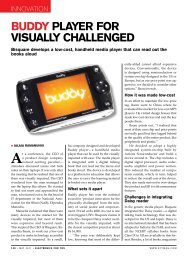
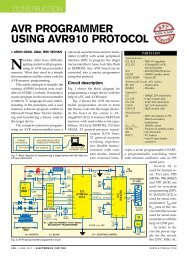
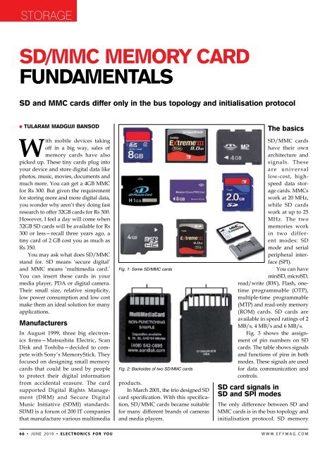
Fig. 1: Some SD/MMC cards<br />
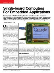
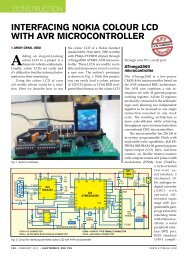
Fig. 2: Backsides of two SD/MMC cards<br />
products.<br />
In March 2001, the trio designed SD<br />
card specification. With this specification,<br />
SD/MMC cards became suitable<br />
for many different brands of cameras<br />
and media players.<br />
The basics<br />
SD/MMC cards<br />
have their own<br />
architecture and<br />
signals. These<br />
are universal<br />
low-cost, highspeed<br />
data storage<br />
cards. MMCs<br />
work at 20 MHz,<br />
while SD cards<br />
work at up to 25<br />
MHz. The two<br />
memories work<br />
in two different<br />
modes: SD<br />
mode and serial<br />
peripheral interface<br />
(SPI).<br />
You can have<br />
miniSD, microSD,<br />
read/write (RW), Flash, onetime<br />
programmable (OTP),<br />
multiple-time programmable<br />
(MTP) and read-only <strong>memory</strong><br />
(ROM) cards. SD cards are<br />
available in speed ratings of 2<br />
MB/s, 4 MB/s and 6 MB/s.<br />
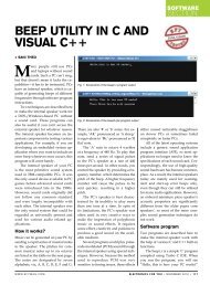
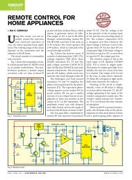
Fig. 3 shows the assignment<br />
of pin numbers on SD<br />
cards. The table shows signals<br />
and functions of pins in both<br />
modes. These signals are used<br />
for data communication and<br />
controls.<br />
<strong>sd</strong> card signals in<br />
<strong>sd</strong> and sPi modes<br />
The only difference between SD and<br />
MMC cards is in the bus topology and<br />
initialisation protocol. SD <strong>memory</strong><br />
6 6 • June 2 0 1 0 • electronics for you w w w . e f y m a g . c o m
Storage<br />
Fig. 3: SD/MMC <strong>memory</strong> card pins<br />
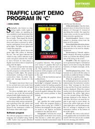
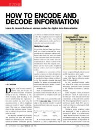
Fig. 5: Interfacing of SD <strong>memory</strong> card to the host<br />
Fig. 6: SD <strong>memory</strong> card architecture<br />
Signals and Functions of SD <strong>Card</strong> Pins in<br />
SD and SPI Modes<br />
Pin Signal Function (SD mode) Function (SPI mode)<br />
1 DAT3/CS Data line 3 Chip select/slave select (SS)<br />
2 CMD/DI Command line Master-out slave-in (MOSI)<br />
3 VSS1 Ground Ground<br />
4 VDD Supply voltage Supply voltage<br />
5 CLK Clock Clock (SCLK)<br />
6 VSS2 Ground Ground<br />
7 DAT0/DO Data line 0 Master-in slave-out (MISO)<br />
8 DAT1/IRQ Data line 1 Unused or IRQ<br />
9 DAT2/NC Data line 2 Unused<br />
interfaces to the host<br />
point-to-point (in Fig.<br />
5, an ARM microcontroller<br />
is the host). This<br />
type of interfacing is<br />
very popular in the<br />
industry.<br />
In serial peripheral<br />
interface (SPI) mode,<br />
you can use following<br />
signals of the host:<br />
1. CS: Host to card<br />
chip-select signal<br />
2. CLK: Host to<br />
card clock signal<br />
3. MOSI<br />
(master-out<br />
slave-in): Host<br />
to card singlebit<br />
data signal<br />
4. MISO<br />
( m a s t e r - i n<br />
s l a v e - o u t ) :<br />
<strong>Card</strong> to host<br />
single-bit data<br />
signal<br />
Now many<br />
companies are<br />
manufacturing<br />
suitable<br />
hosts for the<br />
SD bus interface.<br />
For example,<br />
Philips<br />
is manufacturing<br />
LPC2148<br />
microcontroller<br />
with MOSI<br />
a n d M I S O<br />
signals.<br />
Master-slave mode of communication<br />
is used for multiple slave<br />
devices in the SD architecture. MOSI<br />
is a unidirectional signal used to<br />
transfer serial data from the master<br />
to the slave. When the host is master,<br />
data can move from the host to the SD<br />
card. That’s why MOSI is connected to<br />
data input (DI) of the SD/MMC card.<br />
The MISO signal transfers serial data<br />
from the slave to the master. When<br />
the SD is a slave, serial data is output<br />
on MISO signal. When the SD is a<br />
master, it clocks in serial data from<br />
this signal.<br />
SD <strong>memory</strong> cards use 1- or 4-bit<br />
bus width and star topology to connect<br />
multiple cards, while MMC cards use<br />
1-bit bus width and bus topology for<br />
reading multiple cards.<br />
Fig. 6 shows the internal architecture<br />
of an SD <strong>memory</strong> card. There<br />
are various components in the card<br />
such as operation conditions register,<br />
card identification number (card individual<br />
number for identification),<br />
driver stage register and relative card<br />
address (local system address of a<br />
card, dynamically suggested by the<br />
card and approved by the host during<br />
initialisation). Memory core is the<br />
actual storage of the <strong>memory</strong>. This is<br />
a very compact and delicate architecture.<br />
�<br />
The author is working as an information security<br />
consultant with MIEL eSecurity Pvt Ltd, Andheri<br />
(East), Mumbai<br />
6 8 • June 2 0 1 0 • electronics for you w w w . e f y m a g . c o m