PHOENICS - Arcofluid
PHOENICS - Arcofluid
PHOENICS - Arcofluid

Create successful ePaper yourself
Turn your PDF publications into a flip-book with our unique Google optimized e-Paper software.
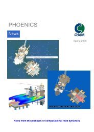
<strong>PHOENICS</strong><br />
News<br />
Editorial<br />
Brian Spalding at The ICHMT international symposium,<br />
Marrakech, Morocco May 11 – 16 2008<br />
On May 12 CHT’08 on Advances in Computational<br />
Heat Transfer opened with a Keynote Lecture by<br />
Brian Spalding. The Conference, attended by some<br />
250 delegates, was organized by the International<br />
Centre for Heat and Mass Transfer, an institution<br />
co-founded by Brian in 1968 and originally based in<br />
Yugoslavia to allow scientists from East and West<br />
to meet and exchange ideas.<br />
The Meeting, in the words of its organizers, was<br />
“planned as a tribute to Professor D Brian Spalding<br />
FRS in honour of his 85 th birthday and in<br />
recognition of his innumerable contributions to<br />
computational fluid dynamics and heat transfer”. It<br />
was fitting that the occasion coincided with the<br />
40 th anniversary of the founding of the ICHMT.<br />
Brian’s opening lecture was entitled Extending the<br />
Frontiers of Computational Heat Transfer in which<br />
he outlined work done over the course of his career<br />
with reference to those who influenced him in the<br />
early days, positive interactions with students, and<br />
his strong recommendation that the boundaries of<br />
computational heat transfer be further extended by<br />
those currently in the field. [Link to Presentation]<br />
The conference was extremely well-attended.<br />
Brian enjoyed meeting colleagues, students and,<br />
particularly, young engineers with an interest in the<br />
field. All enjoyed the scientific interchange, not to<br />
mention the environment and delicious food.<br />
Graham De Vahl Davis, Eddie Leonardi and their<br />
team did a great job.<br />
Summer 2008<br />
Abstract<br />
Impelled by both practical necessity and scientific<br />
interest, the boundaries of computational heat<br />
transfer, and also the relative emphases given to<br />
its various aspects, have changed significantly in<br />
the past decades; but the pace of change has<br />
slowed, in some sectors almost to a standstill. It is<br />
argued in this paper that movement can be, and<br />
should be, resumed and that its speed should<br />
accelerate.<br />
Three particular directions in which extension of<br />
boundaries should be made are advocated, namely:<br />
1) stress analysis in solids<br />
2) multi-phase flow and<br />
3) chemically reacting materials<br />
and it is argued that, in respect of the last two, a<br />
shift of emphasis is desirable towards<br />
consideration of distributions in population space.<br />
Some of the obstacles to making these changes<br />
are spelled out. They can be classified as<br />
psychological, computational and conceptual, the<br />
last of which presents the greatest challenge.<br />
Means of removing some obstacles are proposed<br />
and briefly demonstrated.<br />
Marrakech Photo Gallery<br />
Brian demonstrating<br />
two-fluid mixing<br />
processes to Professor<br />
Graham de Vahl Davis -<br />
Conference Organizer<br />
Left to Right<br />
Andrew<br />
Pollard,<br />
Gordon<br />
Mallnson,<br />
Brian<br />
Spalding ,<br />
Suhas<br />
Patankar<br />
Contents List<br />
Page 1 – Editorial / Marrakech Photo Gallery<br />
Page 2 – What’s New in <strong>PHOENICS</strong><br />
Page 3 – INFORM Patches / Computer Spec<br />
Page 4 – Applications Update<br />
– Gas-fired Carrousel Furnace<br />
Page 5 – TVA’s River Projects<br />
Page 7 – Continuous Casting SEN tube<br />
Page 8 – Vascular Profiling<br />
Page 9 – F1 Champions / News & Events<br />
Left to Right<br />
Norberto Fueyo,<br />
Brian Spalding,<br />
Steven Beale<br />
News from the pioneers of computational fluid dynamics 1
<strong>PHOENICS</strong><br />
News<br />
What’s New in <strong>PHOENICS</strong> 2008<br />
Summer 2008<br />
Just a few of the updated features since the<br />
August 2007 release of <strong>PHOENICS</strong> are outlined<br />
below:<br />
General<br />
o<br />
o<br />
Objects can be tagged always to be at the<br />
domain end, and to extend to the domain end.<br />
This makes changing the domain size easier as<br />
tagged objects will follow automatically.<br />
For the WIND_PROFILE object, the profile<br />
starts in the first un-blocked cell in each<br />
column of cells. Previously it always started at<br />
the lower boundary of the object. This makes<br />
it easier to introduce wind profiles over terrain<br />
objects, as shown simply below<br />
Earth Solver<br />
o<br />
o<br />
o<br />
o<br />
MOFOR & CVD have been enabled in parallel<br />
<strong>PHOENICS</strong>.<br />
In INFORM, to reference the value of a variable<br />
at a specific location, the physical co-ordinates<br />
can be enclosed in { }, for example the<br />
temperature at (3.2,5.8,2.5) is<br />
TEM1{3.2&5.8&2.5}. Previously only cell<br />
locations could be given as TEM1[3&8&5].<br />
A better initial guess at the size of the F array<br />
required for the case has been provided. If a<br />
further expansion fails due to lack of memory,<br />
a scratch file is used for temporary storage.<br />
This allows bigger cases to run on 32-bit<br />
systems without adjustment of CHAM.INI.<br />
The use of material >= 299 for blockage<br />
causes cut cells to be treated as blocked and<br />
opens un-cut cells. The image shows the<br />
detection of a variety of curved surfaces.<br />
o In FLAIR, diffusers can be rotated about any<br />
axes, thus allowing them to be mounted on<br />
sloping surfaces.<br />
o Objects can still be selected when grid mesh<br />
display is on by holding down the Ctrl key.<br />
o INFORM and other utilities are now supplied as<br />
executables, so there is no need to install TCL.<br />
o Drawing of objects in wire-frame has been<br />
enabled on a per-object basis.<br />
o Separate increment sizes are available for each<br />
direction, which is particularly helpful in tunnel<br />
simulations.<br />
o Snap-to-grid feature - objects must be<br />
multiples of increment.<br />
o PHOTON-style PLINE elements can now be<br />
read from macros by the Viewer.<br />
o<br />
o<br />
Screen images can be saved as .JPG files.<br />
In FLAIR, the fire and smoke dialogs have been<br />
updated to use current standards terminology.<br />
The Smoke Settings dialog now refers to Heat<br />
of Combustion, Particulate smoke yield and<br />
Mass specific extinction coefficient. These<br />
values can be found in references such as the<br />
CIBSE Guide E.<br />
Coming shortly<br />
o Improved FACETFIX, which will split an STL<br />
file containing multiple closed bodies into<br />
individual STL files. These can then be<br />
imported as a group preserving their relative<br />
positions. The Earth solver finds it much easier<br />
to handle multiple-interpenetrating objects<br />
when they are separate objects than when<br />
they are all in a single object.<br />
News from the pioneers of computational fluid dynamics 2
<strong>PHOENICS</strong><br />
News<br />
Example of Deflector Blades defined<br />
as ‘patches’ using IN-FORM<br />
The INFORM example (below) defines a trial<br />
box with entry deflector plates mounted just<br />
after the inlet throat of the ductwork. There<br />
is a uniform inlet velocity at the 3m x 4m<br />
rectangular inlet ductwork of 9.745 m/s.<br />
Vertically- and Horizontally-Splayed Blades<br />
The object of the exercise is to improve the<br />
circulation of the gas flow using blades at<br />
various angles.<br />
Velocity – X plane<br />
The geometry was imported as a solid model.<br />
Rather than importing different geometries<br />
each time to adjust the deflector blade angles,<br />
this was done simply through ‘patches’ and<br />
modification of one or two variables defined<br />
as formulae using IN-FORM statements.<br />
Summer 2008<br />
Computer Specification for <strong>PHOENICS</strong><br />
We are often requested to provide the<br />
specification of a recommended computer<br />
system to run <strong>PHOENICS</strong>.<br />
We have found the Intel Core2 Duo chips run<br />
faster than the equivalent AMD dual core. If<br />
users are buying new, it is probably as well<br />
to buy the 64bit Windows OS (XP or Vista) to<br />
make full use of the memory available. For a<br />
dual core we recommend at least 4GB of<br />
RAM; or for quad-core, 8GB or 16GB.<br />
Picture courtesy of Dell Computers<br />
The 32bit<br />
version of<br />
<strong>PHOENICS</strong><br />
does run<br />
slightly faster<br />
than the<br />
64bit version<br />
under 64bit<br />
Windows.<br />
The primary advantage of the 64bit version of<br />
<strong>PHOENICS</strong> is that it can exceed the 2GB limit<br />
for individual programs. Ultimately, the RAM<br />
requirement is determined by the size of the<br />
model the customer expects to create. We do<br />
not have any specific recommendations for<br />
graphic cards. Most modern graphic cards<br />
with 256MB memory should perform<br />
adequately with <strong>PHOENICS</strong>. Hardware<br />
acceleration on some cards can lead to<br />
refresh problems within the Editor; Although<br />
we have not been completely able to solve<br />
this issue, we do have some ‘work-arounds’<br />
that we can enable.<br />
Steve Mortimore email: scm@cham.co.uk<br />
<strong>PHOENICS</strong> 2008 may now be ordered<br />
for 32-bit and 64-bit Windows and LINUX<br />
systems, in both sequential- and parallelprocessing<br />
variants.<br />
The recompilable versions use the INTEL<br />
FORTRAN compiler.<br />
Velocity – Y plane<br />
News from the pioneers of computational fluid dynamics 3
<strong>PHOENICS</strong><br />
News<br />
Summer 2008<br />
Applications Update<br />
Geert Janssen reports on A2TE’s<br />
recent application of <strong>PHOENICS</strong> for a<br />
Gas-fired Carrousel Furnace<br />
The pictures show a simulation of a gas-fired<br />
carrousel furnace that is used to ‘bake’<br />
casting cores made out of ceramic material.<br />
The cores are visible as pink cylinders placed<br />
above a small conical stand.<br />
The nice thing about this simulation is the<br />
combination of convective and radiative heat<br />
transfer (the IMMERSOL model has been<br />
used). Furthermore a semi-static calculation<br />
was done to show the effect of the colder<br />
incoming cores, 10 minutes after placing a<br />
new core in the furnace (at the right side of<br />
the pictures). The more or less spoke-like<br />
open areas in the temperature plots show the<br />
locations of the gas burners, injecting hot<br />
gases at temperatures above 1000°C. The<br />
gases leave the furnace through the centre via<br />
a ring-like opening near the bottom of the<br />
product area.<br />
<strong>PHOENICS</strong> was used to define the optimum<br />
position of the gas burners and the flue gas<br />
opening in the centre of the furnace.<br />
Figure 2 Cross sectional view<br />
Figure 3 Top view<br />
Figure 4 Design of furnace<br />
Ir Geert Janssen A2TE<br />
Email: gjanssen@a2te.nl<br />
Figure 1 Isometric view<br />
News from the pioneers of computational fluid dynamics 4
<strong>PHOENICS</strong><br />
News<br />
<strong>PHOENICS</strong> Applications by the<br />
Tennessee Valley Authority (TVA)<br />
Summer 2008<br />
Computed Velocity Profile Contours at Several Locations<br />
of the Skimmer Wall<br />
TVA’s Boualem (Bo) Hadjerioua describes three<br />
TVA projects using <strong>PHOENICS</strong>. In the first two<br />
examples, several millions of dollars were saved.<br />
The full report can be found at:<br />
http://www.cham.co.uk/casestudies/Summary_PH<br />
OENICS_Projects.pdf<br />
1. TVA’s Colbert Fossil Plant Skimmer Wall<br />
The purpose of this study is to design an optimum<br />
skimmer wall at Colbert Fossil Plant (COF) to reduce derating<br />
due to thermal compliance and debris entrainment<br />
in the COF intake channel. The report presents the<br />
justification, potential benefits and the proposed design<br />
of a skimmer wall at COF.<br />
Barge Collecting Debris at COF, 2001<br />
The estimated capital cost to built a skimmer wall at COF<br />
is about $1.4 million. Therefore, just the savings from<br />
1999-2000 covered the cost of the skimmer wall, which<br />
is expected to last more than 50 years.<br />
Numerical modelling of the intake channel, with skimmer<br />
wall bottom at elevation 400 feet, has shown that the<br />
maximum velocity below the skimmer wall is 1.5 fps<br />
compared to the existing conditions of 0.5 fps. The<br />
computed velocity profiles were used to evaluate the<br />
316b issues (fish entrainment/ impingement by intake<br />
structures).<br />
2. TVA’s Kingston Fossil Plant Multi-Ports<br />
Diffusers<br />
Water temperature monitoring at COF indicates that an<br />
improvement in water temperature could be made if<br />
water is withdrawn from bottom layers of the Tennessee<br />
River. Installing a skimmer wall at the appropriate<br />
location and depth would accomplish this goal.<br />
A reduction system for control of nitrogen oxides (NOx) in<br />
the air emissions is being implemented at Kingston Fossil<br />
Plant (KIF). This new technique uses ammonia to reduce<br />
the emissions. The fly ash combustion by-product<br />
contains ammonia. The fly ash is sluiced to a series of<br />
ponds for settling, and the sluice-water is discharged<br />
from the ash pond into the intake channel.<br />
Survey at KIF intake Channel<br />
The study determined the optimum location and depth of<br />
the skimmer wall to minimize de-rating at COF without<br />
any negative environmental impact. COF also<br />
experienced a big inflow of debris that affected the plant<br />
generation’s efficiency. Therefore, by building a skimmer<br />
wall, two objectives would be targeted; lowering the<br />
intake water temperature during thermal stratification,<br />
and blocking the debris from getting in the intake<br />
channel. However, it was necessary to justify its<br />
implementation and the associated capital cost.<br />
A detailed study of the water temperature profile has<br />
shown that if a skimmer wall is built at COF with a<br />
bottom elevation at 400 feet, the savings from thermal<br />
compliance would have been about $354,000 in 1999.<br />
The debris problem at COF cost 80,000 MWh of derating<br />
at the plant in 2000.<br />
The maximum ammonia concentration entering the intake<br />
channel is predicted to be 2.85 mg/L. At such elevated<br />
levels, ammonia can be toxic to aquatic life. It potentially<br />
adds to the biological oxygen demand, lowering dissolved<br />
oxygen levels and encourages algal blooms. KIF is<br />
evaluating alternatives to avoid violating water quality<br />
standards for ammonia and prevent potential fish kills.<br />
News from the pioneers of computational fluid dynamics 5
<strong>PHOENICS</strong><br />
News<br />
Velocity Vector taken at<br />
Several Intake Channel<br />
Sections<br />
One proposed alternative<br />
is to route the ash pond<br />
discharge into the<br />
condenser cooling water<br />
discharge, where it would<br />
be fully mixed and diluted.<br />
The estimated cost for this option is about 8 million<br />
dollars. A less costly proposed alternative, costing about<br />
500 thousand dollars, is to discharge from the ash pond<br />
through a diffuser system added onto the existing<br />
discharge pipes to enhance mixing and dilution in the<br />
intake channel.<br />
Diffusers Angled at 45<br />
degree, Instantaneous<br />
Mixing<br />
A detailed modeling study<br />
of the intake channel flow<br />
patterns was carried out<br />
to optimize the design of<br />
the diffuser system to<br />
facilitate instantaneous<br />
mixing in the intake channel, maximize dilution, and thus,<br />
bring the ammonia (NH3) concentration to acceptable<br />
levels in the intake channel. The modeling results show<br />
an instantaneous mixing and reduction in NH3 to about<br />
0.23 Mg/L within 140 feet downstream the diffusers,<br />
concentration well below the Criteria Continuous<br />
Concentration (CCC) of 0.55 mg/L for KIF intake channel.<br />
Model Layout (Base Case)<br />
Summer 2008<br />
The modeling of the alternative layouts was evaluated under<br />
summer pool elevation with a relatively strong thermal<br />
stratification and a relatively high DO content only in the<br />
upper few feet of the reservoir. <strong>PHOENICS</strong> was used to<br />
evaluate the flow field, water temperature, and DO<br />
improvements. Turbulence was accounted for by using the<br />
K-E turbulence model, and the Boussinesq approximation<br />
was used to include the domain buoyancy effects. The<br />
report presents the modeling results of surface water pump<br />
designs, locations, and operating speeds under summer pool<br />
reservoir elevation for three and six pump layouts<br />
.<br />
Computed Temperature at Intake Vertical Centerline (Six<br />
Pumps)<br />
3. TVA’s Tims Ford Reservoir Surface Water<br />
Pumps<br />
The report describes the numerical simulation of surface<br />
water pump performance at Tims Ford Dam. The modeling<br />
objective was to evaluate surface water pumps<br />
performance under several configurations, pump sizes, and<br />
initial propeller velocities.<br />
Surface-water pumps being ssed at Douglas and<br />
Cherokee Reservoirs<br />
Computed DO at Intake Vertical Centerline (Six Pumps)<br />
The goal was to determine an optimum design to maximize<br />
the improvement of water temperature and dissolved<br />
oxygen (DO) content in hydropower plant releases without<br />
disturbing reservoir bottom sediment. The results for two<br />
alternatives are presented; a three 12-ft pump and a six 8-ft<br />
pump layout.<br />
Based on the comparison of several surface pumps layout<br />
scenarios, the recommended option of surface water<br />
pumps for Tims Ford Forebay Reservoir is the six 8-ft<br />
pump layout. Under the June 26, 2003, forebay profile,<br />
this option improved the water temperature release by<br />
10.3°F and the DO by 2.0 mg/L.<br />
Boualem (Bo) Hadjerioua<br />
Email: bhadjerioua@tva.gov<br />
News from the pioneers of computational fluid dynamics 6
<strong>PHOENICS</strong><br />
News<br />
Redesign of SEN tube for Continuous<br />
Casting of Steel<br />
The SEN (Submerged Entry Nozzle) tube in<br />
continuous casting delivers liquid steel from a<br />
reservoir (Tundish) to the mold for final<br />
solidification into slabs. At United States Steel<br />
Corporation (“U. S. Steel”), the SEN tube has two<br />
port openings from which the steel enters the mold<br />
from the tundish. The ports have a down angle to<br />
direct the flow down inside the mold and the ports<br />
are located slightly above the bottom plane of the<br />
SEN, so that there is an internal recess or cup<br />
height. Recently, use was made of <strong>PHOENICS</strong> fluid<br />
dynamics software to mathematically model the<br />
flow of liquid steel in the mold.<br />
The work involved increasing the useful life of the<br />
SEN tube being used at a U. S. Steel plant. Since<br />
the tube life was dictated primarily by mold flux<br />
attack on the tube refractory at the liquid interface,<br />
increased thickness of the SEN refractory wall by<br />
reducing the inner bore diameter of the tube, would<br />
help to increase the life of the tube. However,<br />
when the plants initially reduced the inner bore<br />
diameter from 90 to 80mm, the flow speeded up<br />
and changed significantly near the liquid surface,<br />
such that mold flux powder on the steel surface<br />
was being entrapped into the steel, thus reducing<br />
steel cleanliness and quality. Mathematical<br />
modeling of the flow in the mold was performed to<br />
solve this problem.<br />
Using <strong>PHOENICS</strong>, the flow profile in the mold was<br />
computed for the existing SEN design, the<br />
unsuccessful reduced bore design and some new<br />
proposed designs incorporating the reduced bore<br />
technology. The velocity and turbulence values at a<br />
plane near the liquid surface were recorded for all<br />
the cases. The objective was to match the velocity<br />
and turbulence values generated by the proposed<br />
reduced bore design as close as possible to that<br />
generated by the existing big bore SEN design near<br />
the top surface of the liquid, which is the region<br />
where the mold flux powder was being entrapped.<br />
To model the free surface at the top, the IPSA<br />
algorithm was employed. The KE model was used<br />
to model the turbulence and a fixed volumetric<br />
flow rate condition was imposed at the inlet.<br />
The steel flow pattern at t=25seconds for the<br />
current big bore tube is shown in Figure 1 while<br />
Table 1 is a partial list of the different SEN designs<br />
that were investigated. Version K is the big bore<br />
tube, version A is the unsuccessful reduced bore<br />
design and version X is a new reduced bore design.<br />
Summer 2008<br />
Table 1: Description of all the different SEN tube designs<br />
investigated<br />
Tube Type Version Description<br />
Index<br />
Current J Tube K Bore 90, Port 70x90,<br />
Angle 15, CupHt 66<br />
SmallBore<br />
X Bore 80, Port 70x80,<br />
ModifiedPort<br />
Angle 20, CupHt 55<br />
Experimental L A Bore 80, Port 70x80,<br />
Tube<br />
Angle 15, CupHt 66<br />
Figure 1: Schematic of the liquid steel flow in the mold<br />
from the two-ported SEN.<br />
Velocity (m/s)<br />
0.035<br />
0.03<br />
0.025<br />
0.02<br />
0.015<br />
0.01<br />
0.005<br />
0<br />
Velocity Values Near Top Surface of Liquid<br />
0 0.1 0.2 0.3 0.4 0.5 0.6<br />
Distance from Mold End Wall (m)<br />
Current J Tube-VerK<br />
Reduced Bore Tube-VerA<br />
Reduced Bore Mod-VerX<br />
SBoreJ-VerS<br />
SBoreLModPortsFlare-VerF<br />
Figure 2: velocity values near top surface of liquid for<br />
different SEN designs.<br />
Figure 2 shows the velocity values along a line near<br />
the top surface of the liquid in the mold, extending<br />
from one end of the mold to the other along the<br />
centerline. All the different designs investigated,<br />
version X (red line) has the closest match to version K<br />
(blue line) the current big bore tube. Version A (pink<br />
line), the unsuccessful tube shows higher velocity<br />
over most of the surface compared to version K and<br />
caused the mold flux entrapment. Thus version X<br />
design was trialed in the plant and the tube life index<br />
improved from a value of 0.68 to 1.0 i.e. almost 50%<br />
improvement and this design has been currently<br />
adopted for use at the plant leading to cost savings.<br />
Dr A K Sinha,<br />
Email: ASinha@uss.com<br />
News from the pioneers of computational fluid dynamics 7
<strong>PHOENICS</strong><br />
News<br />
Vascular Profiling at Brigham &<br />
Women’s Hospital, & Harvard Medical<br />
School<br />
Dr Ahmet Umit Coskun, Dr Charles L<br />
Feldman, Northeastern University<br />
The Vascular Profiling Laboratory at Brigham &<br />
Women’s Hospital/Harvard Medical School, under<br />
the direction of Charles L. Feldman, ScD, has used<br />
<strong>PHOENICS</strong> to predict the progression of coronary<br />
atherosclerosis (fatty deposits in the heart’s<br />
arteries) in patients and to explore the mechanisms<br />
of coronary atherosclerosis in swine with artificially<br />
induced diabetes and abnormally high cholesterol.<br />
Dr A U Coskun, the Lab’s Technical Director,<br />
employed a body-fitted coordinate (BFC) mesh to<br />
simulate blood flow through coronary arteries. The<br />
original geometry/anatomy was obtained through a<br />
combination of x-ray and ultrasound images. Flow<br />
rates were obtained by tracking X-ray contrast<br />
(“dye”) through an artery, and patient specific<br />
viscosity was determined from routine blood tests.<br />
The entire process was shown to be highly<br />
reproducible in-vivo [1] . Local sites of low<br />
Endothelial (surface) Shear Stress (ESS) determined<br />
through the simulations agree well with the sites of<br />
coronary artery disease progression [2] .<br />
Animal studies have shown that ESS is<br />
quantitatively related to the clinical significance of<br />
the disease – the lower the ESS the more<br />
dangerous the disease build-up is likely to be [3] .<br />
These results strongly suggest that the use of CFD<br />
to analyze coronary artery flow can lead to a<br />
paradigm shift in patient management and can help<br />
to prevent heart attacks [4] .<br />
Figure illustrates the grid formed at a coarser density than<br />
the one used in simulations for clarity. Body fitted<br />
coordinates available in <strong>PHOENICS</strong> was a natural fit to<br />
the complex coronary artery geometries with the disease.<br />
The geometry is from a right coronary artery indicated by<br />
the arrows in the x-ray angiogram.<br />
Summer 2008<br />
Figure shows a time snapshot of the velocity<br />
profile at a cross-section and the surface shear<br />
stress distribution at two different angles (front<br />
and back with respect to the grid). Local<br />
variations of shear stress due to curvature and/or<br />
surface irregularities are apparent and known to<br />
correlate with progression of coronary artery<br />
disease.<br />
1. Coskun, A.U., et al., “Reproducibility of<br />
coronary lumen, plaque, and vessel wall<br />
reconstruction and of endothelial shear stress<br />
measurements in-vivo in humans,”<br />
Catheterization and Cardiovascular<br />
Interventions, 60: 67-78, 2003.<br />
2. Stone, P.H., et al., “Effect of endothelial<br />
shear stress on the progression of coronary<br />
artery disease, vascular remodeling, and instent<br />
restenosis in humans: In-vivo 6-month<br />
follow-up study,” Circulation, 108:438-444,<br />
2003.<br />
3. Chatzizisis Y. S., et al., “Prediction of the<br />
Localization of High-Risk Coronary<br />
Atherosclerotic Plaques on the Basis of Low<br />
Endothelial Shear Stress: An Intravascular<br />
Ultrasound and Histopathology Natural<br />
History Study,” Circulation, 117:993-1002,<br />
2008.<br />
4. Chatzizisis, Y.S., et al, “Risk Stratification of<br />
Individual Coronary Lesions Using Local<br />
Endothelial Shear Stress: A New Paradigm<br />
for Managing Coronary Artery Disease,”<br />
Current Opinion in Cardiology, 28:552-564,<br />
2007.<br />
Dr. Ahmet Umit COSKUN<br />
Associate Research Engineer<br />
E-Mail: acoskun@coe.neu.edu<br />
News from the pioneers of computational fluid dynamics 8
<strong>PHOENICS</strong><br />
News<br />
Training dates:<br />
Summer 2008<br />
Pulse Crowned as F1 in Schools World<br />
Champions !!<br />
The F1 in Schools Technology Challenge is for<br />
school children aged 11 to 18 to use CAD/CAM<br />
software to design, analyse, manufacture, test and<br />
race their miniature F1 car made from balsa wood<br />
and powered by CO2 cylinders.<br />
A sub-set of <strong>PHOENICS</strong>, the F1 VWT, is used to<br />
test prototype designs in a virtual wind tunnel prior<br />
to production. For a description of the F1 VWT,<br />
see: www.cham.co.uk/DOCS/f1_VWT_Flyer.pdf.<br />
The hugely popular and highly competitive F1 in<br />
Schools Challenge involves thousands of<br />
schoolchildren from all over the world – See:<br />
www.f1inschools.co.uk.<br />
CHAM, London: 28 th to 30 th May 2008<br />
SEAS, Singapore 6 th to 8 th August 2008<br />
http://www.seas.org.sg/<br />
CHAM, London: 22 nd to 24 th July 2008<br />
CHAM, London: 16 th to 18 th September 2008<br />
See http://www.cham.co.uk/training.php for<br />
updated <strong>PHOENICS</strong> training course dates and<br />
programme.<br />
News & Events<br />
Consultancy Manager Appointment<br />
We welcome Mr Paul Emmerson to our team here<br />
in the UK. Paul joins us from QinetiQ, Farnborough,<br />
and will take on a leading role in CHAM’s<br />
expanding consultancy activities in the UK.<br />
As well as targetting the<br />
chemical and turbomachinery<br />
industries for which his<br />
experience will be especially<br />
valuable, he also inherits<br />
responsibility for two ongoing<br />
DTI and EU projects focussed<br />
on nano-particle applications.<br />
Welcome to the deep end Paul !<br />
After 3 days of intense competition, the ‘Pulse’<br />
team from Devonport High School for Boys has<br />
been crowned “F1 in Schools World Champions!”<br />
They also came away from the International Finals<br />
held in Kuala Lumpur, Malaysia, with the Fastest<br />
Car award, after achieving a track time of 1.064<br />
seconds - a scaled up speed of over 220mph. The<br />
judges said Pulse scored well with an impressive<br />
portfolio and clinical presentation to clinch the<br />
highest points total and scoop the title of “2008<br />
World Champions”.<br />
In order to finance the cost of developing the CO2<br />
powered model and their trip to Malaysia, the team<br />
managed to raise £11,500 in sponsorship from<br />
both local and national companies. Teacher and<br />
Team Manager, John Ware, said “I would like to<br />
thank all of our sponsors, as well as everyone in<br />
Malaysia for making us feel so welcome."<br />
John Ware, Pulse, Devonport High School for Boys<br />
Email: john@pulsef1.co.uk<br />
Web: www.pulsef1.co.uk<br />
CHAM still has recruitment opportunities<br />
for both technical support and consultancy<br />
engineers, so applicants should please send their<br />
CV’s to phoenics@cham.co.uk marked for the<br />
attention of Jill Rayss.<br />
CHAM-Japan will exhibit <strong>PHOENICS</strong> at DMS in<br />
Tokyo.<br />
DMS Tokyo 2008 -<br />
25 to 27 June<br />
http://www.dmstokyo.jp/dms/english/<br />
Contributions<br />
We are always interested in receiving<br />
contributions for the Newsletter from Agents,<br />
<strong>PHOENICS</strong> Users and Students. Please email<br />
to <strong>PHOENICS</strong>@cham.co.uk. Full attribution<br />
will be given to all contributions used.<br />
News from the pioneers of computational fluid dynamics 9