DUCT-O-BAR Figure 8 Electrical Conductor Systems - Duct-O-Wire
DUCT-O-BAR Figure 8 Electrical Conductor Systems - Duct-O-Wire
DUCT-O-BAR Figure 8 Electrical Conductor Systems - Duct-O-Wire
You also want an ePaper? Increase the reach of your titles
YUMPU automatically turns print PDFs into web optimized ePapers that Google loves.
®<br />
®<br />
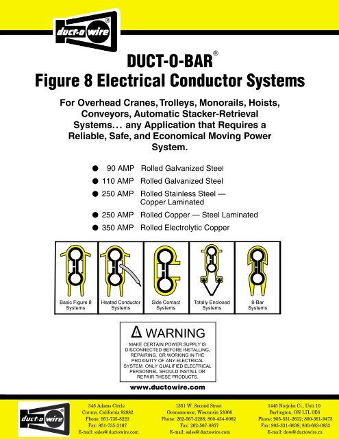
<strong>DUCT</strong>-O-<strong>BAR</strong><br />
<strong>Figure</strong> 8 <strong>Electrical</strong> <strong>Conductor</strong> <strong>Systems</strong><br />
For Overhead Cranes, Trolleys, Monorails, Hoists,<br />
Conveyors, Automatic Stacker-Retrieval<br />
<strong>Systems</strong>... any Application that Requires a<br />
Reliable, Safe, and Economical Moving Power<br />
System.<br />
•<br />
90 AMP Rolled Galvanized Steel<br />
•<br />
110 AMP Rolled Galvanized Steel<br />
•<br />
•<br />
250 AMP<br />
•<br />
350 AMP<br />
250 AMP Rolled Stainless Steel —<br />
Copper Laminated<br />
Rolled Copper — Steel Laminated<br />
Rolled Electrolytic Copper<br />
Basic <strong>Figure</strong> 8<br />
<strong>Systems</strong><br />
Heated <strong>Conductor</strong><br />
<strong>Systems</strong><br />
Side Contact<br />
<strong>Systems</strong><br />
Totally Enclosed<br />
<strong>Systems</strong><br />
8-Bar<br />
<strong>Systems</strong><br />
Δ ! WARNING<br />
MAKE CERTAIN POWER SUPPLY IS<br />
DISCONNECTED BEFORE INSTALLING,<br />
REPAIRING, OR WORKING IN THE<br />
PROXIMITY OF ANY ELECTRICAL<br />
SYSTEM. ONLY QUALIFIED ELECTRICAL<br />
PERSONNEL SHOULD INSTALL OR<br />
REPAIR THESE PRO<strong>DUCT</strong>S.<br />
www.ductowire.com
®<br />
U®<br />
L<br />
LISTED<br />
File # E29805<br />
Contr. 678L<br />
Approved<br />
in Canada<br />
Determining Ampere Load<br />
The conductor selected must be large enough to carry the<br />
necessary ampere load safely without undue heating. To<br />
compute the ampere load, proceed as follows:<br />
1. List the horsepower of all motors used in the<br />
application.<br />
2. Determine the voltage and type of current that will feed<br />
the conductor. For example: 230 VDC 2 wire; 460 VAC<br />
3 phase; etc.<br />
3. Refer to the Horsepower Conversion Table on page 3<br />
and convert the horsepower to amperes.<br />
4. Prepare the ampere load figure that will be used to size<br />
the conductors as follows:<br />
List the full load ampere rating of each motor used<br />
on the crane or monorail unit. Determine the duty<br />
cycle from the following paragraphs and apply the<br />
corresponding factor.<br />
Light Duty — Class A and B Crane Service<br />
Standby or infrequent use. Up to two motors started<br />
at a time. Two to five lifts per hour. Use a factor of<br />
90% of the calculated ampere load.<br />
Average Duty — Class C Crane Service<br />
Moderate use during the work day. Five to ten lifts<br />
per hour. Not over 50% of the lift at rated capacity.<br />
Use a factor of 100% of the calculated ampere load.<br />
<strong>Conductor</strong> Bar Selection<br />
Heavy Duty — Class D Crane Service<br />
Used continually during the work day and usually for<br />
more than one shift. Loads of 50% of rated capacity<br />
or more handled constantly during the work period.<br />
Use a factor of 110% of the calculated ampere load.<br />
Severe Duty — Class E and F Crane Service<br />
Used continually for two or more work shifts a day<br />
for loads approaching 100% of capacity. Use a<br />
factor of 120% of the calculated ampere load. Due<br />
to the mechanical considerations on severe duty<br />
use, contact the factory engineering group when<br />
selecting the conductor system for this application.<br />
5. If the conductors are to be located where the ambient<br />
air temperature is unusually high, the current carrying<br />
capacity of the conductor is reduced. Multiply the<br />
current capacity of the selected conductor by the<br />
derating factor in the following table.<br />
Temperature Derating Table<br />
Ambient Air Temperature<br />
Derating Factor<br />
100°F 95%<br />
130°F 75%<br />
160°F* 50%<br />
* At this ambient temperature it will be neccessary to use the higher<br />
rated conductor cover, XHT rated at 280°F. Use of XHT cover at<br />
160°F allows for full ampacity at that temperature.<br />
Determining Voltage Drop<br />
According to CMAA, the voltage drop to the unit motors<br />
shall not be more than 3% from the power taps to the load<br />
at the farthest point on the conductor run. To determine<br />
the voltage drop use the appropriate formula in the<br />
following table.<br />
Current Type<br />
Formula<br />
AC 3 phase 60 cycle V = L x I x Z x 1.73<br />
AC 1 or 2 phase 60 cycle V = L x I x Z x 2<br />
DC 2 wire system V = L x I x R x 2<br />
V = Voltage drop<br />
L = Distance from power feed to end of conductor<br />
I = Total amperes drawn as calculated from<br />
conversion charts<br />
Z = AC impedance<br />
R = DC resistance<br />
See <strong>Conductor</strong> Engineering Data Table on page 4 for<br />
values of Z and R.<br />
Divide voltage drop by system voltage to get the percent<br />
of voltage drop.<br />
Maximum voltage drops that are 3% of various supply<br />
voltages are as follows:<br />
Supply Voltage<br />
Voltage Drop (V)<br />
460 VAC 13.8<br />
230 VAC or VDC 6.9<br />
575 VAC 17.2<br />
Volts lost that are equal to or less than the above values<br />
when using the formulas above will help in selecting the<br />
correct conductor.<br />
2
®<br />
<strong>Conductor</strong> Selection Example<br />
Given a 300 foot runway, power fed at the center, using<br />
460 volt, 3 phase, 60 cycle power supplied to a bridge<br />
crane — there is a 40 h.p. hoist motor, a 20 h.p. bridge<br />
motor, and a 5 h.p. trolley motor. The operation is Average<br />
Duty. Ambient temperature varies from 50°F in winter to<br />
90°F in summer on this Indoor installation.<br />
Step 1 — Determining Ampere Load<br />
See National Electric Code article 610-14(e) for<br />
determining motor loads where there are multiple motors<br />
on a single crane. Then from the Horse Power Conversion<br />
Table 460V column (right):<br />
40 h.p. hoist motor — 52 amps @ 100% = 52 amps<br />
20 h.p. bridge motor — 27 amps @ 50% = 13.5 amps<br />
5 h.p. trolley motor — 7.6 amps @ 50% = 3.8 amps<br />
The total current load is 69.3 amperes.<br />
With Average Duty cycle, the current load is<br />
factored at 100%. Normal ambient conditions of<br />
50°F to 90°F require no temperature derating.<br />
Selecting a 90 amp conductor caused a voltage<br />
drop of 4.3% using the formula. Since this is<br />
unsatisfactory, use a 110 amp conductor (FE-908)<br />
for Step 2.<br />
Step 2 — Determining Voltage Drop<br />
Use the AC 3 phase formula on page two.<br />
V = L x I x Z x 1.73 where:<br />
L = 150 ft. (Distance to the end of the runway from<br />
the center power feed.)<br />
I = 69.3 amperes<br />
Z = .0008 for 110 amp conductor (From the<br />
<strong>Conductor</strong> Engineering Data Table, page 4.)<br />
1.73 = 3 phase constant<br />
V = 150 x 69.3 x .0008 x 1.73<br />
= 14.4 volts<br />
14.4/460 = 3.1%<br />
Since this voltage drop only occurs at the farthest end<br />
when two or more motors are started simultaneously,<br />
exceeding the 3% voltage drop goal by only 0.1% will not<br />
cause a problem.<br />
Horsepower Conversion Table<br />
3 Phase AC — 60 Cycle Direct Current<br />
Amperes<br />
Amperes<br />
h . p. 230V 460V 575V 230V<br />
1/2 2 1 .8 2.7<br />
3/4 2.8 1.4 1.1 3.8<br />
1 3.6 1.8 1.4 4.7<br />
1-1/2 5.2 2.6 2.1 6.6<br />
2 6.8 3.4 2.7 8.5<br />
3 9.6 4.8 3.9 12.2<br />
5 15.2 7.6 6.1 20<br />
7-1/2 22 11 9 29<br />
10 28 14 11 38<br />
15 42 21 17 55<br />
20 54 27 22 72<br />
25 68 34 27 89<br />
30 80 40 32 106<br />
40 104 52 41 140<br />
50 130 65 52 173<br />
60 154 77 62 206<br />
75 192 96 77 255<br />
100 248 124 99 341<br />
125 312 156 125 425<br />
150 360 180 144 506<br />
200 480 240 192 675<br />
Ampere Load Calculations for Multiple Units<br />
For information about sizing ampere loads for multiple<br />
cranes on the same runway, see Article 610-14 (e) of the<br />
National <strong>Electrical</strong> Code for the demand factors. This<br />
article also covers additional loads on the bridge cranes<br />
other than motor loads.<br />
Induction Type Squirrel Cage and Wound Rotor Motors<br />
The Horsepower Conversion Table is taken from the 1996<br />
NEC Article 430. The values are for motors running at<br />
usual speeds with normal torque characteristics. Motors<br />
built for especially low speeds or high torques may require<br />
more running current, and multi-speed motors will have<br />
full-load current varying with speed. In these cases, use<br />
the higher nameplate current rating.<br />
The voltages listed are rated motor voltages. The current<br />
listed shall be permitted for system voltage ranges of 110<br />
to 120, 220 to 240, 440 to 480, and 550 to 600 volts.<br />
Motors rated at 208 VAC should increase the 230 volt<br />
column figures by 10%.<br />
For motors that are wound for single or double phase<br />
operation, use the nameplate rating. For older slip ring<br />
motors or models that have secondary windings be sure to<br />
obtain both primary and secondary current ratings.<br />
Secondary windings may also need separate conductors<br />
or cables when updating the electrification.<br />
3
®<br />
<strong>Conductor</strong> Engineering Data Table<br />
Weight per Ampere Rating Coefficient of Resistance Factor<br />
<strong>Conductor</strong> Description 10' section Linear Expansion AC (z) DC (R) Circular<br />
Bar No. lbs. Continuous Intermittent* per °F ohms/ft. ohms/ft. Mills<br />
FE-758 Galvanized Steel 4.5 90 135 .000007 .0011 .00072 130,000<br />
FE-908 Galvanized Steel 6.5 110 165 .000007 .0008 .0005 189,000<br />
FE-1608 Stainless/Copper Laminate 6.5 250 350 .000008 .000144 .0001 188,000<br />
FE-2008 Copper/Steel Laminate 6.25 250 350 .000008 .000142 .0001 189,000<br />
FE-3008 Rolled Copper 6.75 350 530 .000009 .000085 .000058 188,000<br />
* Intermittent Service Rating is determined for one minute on, one minute off operation.<br />
Miscellaneous Applications<br />
Curves<br />
®<br />
<strong>Duct</strong>-O-Bars, except the Totally Enclosed System, can be<br />
bent to form curved sections without damaging the<br />
insulating cover or conductor. Bends with a five-foot radius<br />
or greater can be done in the field by using a fly wheel,<br />
monorail beam, or similar object to bend the conductor to<br />
approximately the necessary radius. Hangers used on<br />
curved sections must be placed at intervals of 2-1/2 feet<br />
maximium — and closer if required. Use B-100 cross bolt<br />
clamp type hangers and P-Series collectors.<br />
The minimum spacing between conductors on curves is<br />
three inches.<br />
For curves of five-foot radius or more, use five-inch<br />
collector shoes. For curves of less than five-foot radius use<br />
three-inch collector shoes; also consult the factory for<br />
additional information.<br />
Discontinuous Circuits<br />
On discontinuous circuits a pickup guide assembly must<br />
be installed to ensure that the self-centering type collectors<br />
engage and disengage the conductor bar. The pickup<br />
guide (FE-2JNN3 is illustrated) must have its own support<br />
point.<br />
4-1/2"<br />
5' Max.<br />
<strong>DUCT</strong>-O-<strong>BAR</strong><br />
Transfer Cap<br />
10"<br />
Support Point<br />
Pickup Guide<br />
Assembly<br />
3"<br />
Self-Centering<br />
Collector<br />
Interlocks, Switches, or Fixed Gaps<br />
The maximum fixed gap occurring at interlocks is one-inch<br />
when using 100 amp P-Series collectors and 1/2 inch<br />
when using 40 amp collectors. Use transfer caps as shown<br />
to ensure that the collector brushes transfer evenly and<br />
smoothly. Also round both ends of the contact brushes to<br />
facilitate the transfer. Use clamp type hangers only. When<br />
both interlocks and curves of less than a four-foot radius<br />
are encountered, the tandem 40 amp collector is<br />
recommended.<br />
Support Bracket<br />
2-1/2"<br />
Transfer Cap<br />
1" Max. Gap — 100 AMP Collectors<br />
1/2" Max. Gap — 40 AMP Collectors<br />
Support Bracket<br />
Other Special Applications<br />
Consult the factory for recommendations on applications<br />
such as de-icing systems, totally enclosed systems, and<br />
other systems not covered here.<br />
4
®<br />
Expansion Gaps<br />
Expansion gaps should be placed at intervals determined<br />
by 1) the expansion rate of the metal in the conductor<br />
selected, and 2) the variation in temperature that will occur<br />
at the conductor location over a full year of operation.<br />
1. Steel <strong>Conductor</strong> <strong>Systems</strong><br />
Given that steel conductors expand 1" for every 120' of<br />
runway with a temperature change of 100°F over a full<br />
year of operation, put the length of the runway and the<br />
maximum temperature change for the system to be used<br />
into the following formula:<br />
Total Steel Expansion (inches) = X/120' x Y/100°F<br />
where X is the runway length and Y is the 12 month<br />
temperature variation.<br />
Example: A 450' long steel conductor (X) installed in a<br />
building with an indoor temperature change of 40°F (Y).<br />
Total Expansion = 450'/120' x 40°F/100°F = 1.5".<br />
(See Section 3.)<br />
2. Copper <strong>Conductor</strong> <strong>Systems</strong><br />
Given that copper conductors expand 1" for every 100' of<br />
runway over a 100°F temperature change at the conductor<br />
over a full year of operation, put the length of the runway<br />
and the maximum temperature change for the system to<br />
be used into the following formula:<br />
Total Copper Expansion (inches) = X/100' x Y/100°F.<br />
Example: A 300' long copper conductor system (X)<br />
installed outdoors with an anticipated temperature<br />
fluctuation of 80°F (Y).<br />
Total Expansion = 300'/100' x 80°F/100°F = 2.4".<br />
(See Section 3.)<br />
3. Determine the Number of Expansion Gap Assemblies<br />
After calculating the actual expansion of the runway<br />
conductor system, use the following rule of thumb to pick<br />
the number of expansion gap assemblies:<br />
a. Under 1" of expansion, use no expansion assemblies.<br />
Install one anchor clamp set at the center of the<br />
conductor run.<br />
b. From 1" to 2" of expansion, use one expansion<br />
assembly in the center of the conductor run.<br />
c. From 2" to 4" of expansion, use two expansion<br />
assemblies. Locate them at 1/3 of the runway length in<br />
from each end.<br />
d. For systems with more than 4" of expansion, use one<br />
expansion gap assembly for each 2" of expansion.<br />
4. Anchors<br />
Anchor clamps are required at midpoint on all systems<br />
without expansion gaps and halfway between gaps and<br />
from gaps to the end of systems with multiple gaps. See<br />
the <strong>Figure</strong> 8 Installation Instructions on anchor locations.<br />
The maximum gap opening for all ten foot<br />
<strong>Figure</strong> 8 expansion gap assemblies is 1-3/4<br />
inches.<br />
Expansion assemblies are also required at<br />
building expansion joints.<br />
<strong>Conductor</strong> Assembly Selection<br />
®<br />
<strong>Duct</strong>-O-<strong>Wire</strong> <strong>Figure</strong> 8 <strong>Conductor</strong> Bars are furnished as<br />
assemblies consisting of a ten-foot long conductor bar<br />
rated at 600 volts, an insulating cover, splice cover, and<br />
connector pins or joint clamps as applicable.<br />
The insulating cover must be appropriate for the<br />
environment — indoor, outdoor, or high temperature — in<br />
which the conductor is to operate.<br />
Indoor systems are for use in ambient temperatures up to<br />
160°F. They have an Orange PVC Insulating Cover. They<br />
are not recommended for outdoor use in direct sunlight.<br />
Outdoor systems are for use in direct sunlight and ambient<br />
temperatures up to 160°F. They have a Gray PVC<br />
Insulating Cover with an ultraviolet additive.<br />
High temperature systems are for use in ambient<br />
temperatures up to 280°F. They have a Yellow<br />
Polycarbonate Insulating Cover.<br />
From the table to the right, you can select the basic (FE)<br />
conductor assembly with the appropriate bar and<br />
insulating cover for your application.<br />
For information on other conductor assemblies, see page 12.<br />
Basic <strong>Figure</strong> 8 (FE) <strong>Conductor</strong> Assemblies<br />
10 ft. Lengths Assembly Catalog No.<br />
<strong>Conductor</strong> Weight Indoor Outdoor High Temp.<br />
Bar No. Pounds Use Use Use<br />
FE-758 4.5 FE-758-2 FE-758-2-SC FE-758-2XHT<br />
FE-908 6.5 FE-908-2 FE-908-2-SC FE-908-2XHT<br />
FE-1608 6.5 FE-1608-2 FE-1608-2-SC FE-1608-2XHT<br />
FE-2008 6.25 FE-2008-2 FE-2008-2-SC FE-2008-2XHT<br />
FE-3008 6.75 FE-3008-2 FE-3008-2-SC FE-3008-2XHT<br />
Cross-sectional drawing of<br />
Basic <strong>Figure</strong> 8 (FE) <strong>Conductor</strong> Assembly<br />
5
®<br />
Typical <strong>Conductor</strong> Mounting<br />
Note: S indicates minimum conductor spacing.<br />
Standard Vertical Mounted <strong>Conductor</strong>s (Bottom Entry)<br />
3-Phase System • Bottom Contact • 5 Ft. Maximum Support Spacing<br />
Lateral Mounted <strong>Conductor</strong>s (Side Entry)<br />
4 Ft. Maximum Support Spacing.<br />
Use only Lateral (L) Model Collectors.<br />
S<br />
1-1/2" — Single Collectors — Staggered and PS-Series Collectors.<br />
3" — Collectors Adjacent or when Pickup Guides are used.<br />
Insulated Hangers also require 3" spacing<br />
S<br />
Use Metal Hangers Only<br />
on Lateral <strong>Systems</strong><br />
Monorail Application<br />
Install two conductors on one side of the beam and one conductor on the opposite<br />
side to balance the collector spring forces, particularly on light weight hoists.<br />
1-1/2" — Single Collectors — Staggered<br />
3" — Collectors Adjacent or when<br />
Pickup Guides are used. Insulated<br />
Hangers also require 3" spacing.<br />
S<br />
2-1/2"<br />
2-1/2"<br />
S<br />
1-1/2" — Single Collectors – Staggered and PS-Series Collectors.<br />
3" — Collectors Adjacent or when Pickup Guides are used.<br />
Insulated Hangers also require 3" spacing.<br />
®<br />
<strong>Duct</strong>-O-Bar <strong>Figure</strong> 8 (FE) Components<br />
Weight<br />
Catalog Number Pounds Description<br />
Angle Brackets for Web Mounting<br />
Brackets are galvanized 12 gage rolled steel<br />
channel. Hangers are priced separately, but will<br />
be factory installed at no charge when hanger<br />
locations are shown on sketch.<br />
B-100-BR1A 1.00 Bracket — 11-1/4" long.<br />
B-100-BR7A 1.42 Bracket — 15-3/4" long.<br />
B-100-BR7B 1.70 Bracket with gusset support — 15-3/4" long.<br />
B-100-BR13A 1.71 Bracket — 20-1/4" long. Do not use with tandem<br />
collectors.<br />
B-100-BR13B 2.04 Bracket with gusset support — 20-1/4" long.<br />
B-100-BR-EXT<br />
Bracket Extension for Ground Bar<br />
B-100-BR-EXT .31 Bracket — 4th bar extension to be used with<br />
prepunched brackets shown above.<br />
B-100-BR-EXT-XL .27 Bracket — 4th bar extension to be used with<br />
angle iron.<br />
6
®<br />
Weight<br />
Catalog Number Pounds Description<br />
Hole Spacing: 1-1/2 "<br />
Typical Hole Dia.: 7/16"<br />
Capped I-Beam<br />
“J” Bolts: 3/8-16 x 5”<br />
Due to "J" Bolt Thread Length<br />
The Minimum C-Channel Flange<br />
Length is 2.648" (C9 X 20)<br />
Straight Brackets for Top Flange<br />
Mounting<br />
Brackets are galvanized 12 gage rolled steel<br />
channel. Hangers are priced separately, but will<br />
be factory installed at no charge when hanger<br />
locations are shown on sketch.<br />
B-100-BR3A 1.20 Bracket — 18" long.<br />
B-100-BR4A 1.82 Bracket with two Mounting Clamps and<br />
hardware — 18" long.<br />
B-100-BR5A 1.41 Bracket — 21" long.<br />
B-100-BR6A 2.03 Bracket with two Mounting Clamps and<br />
hardware — 21" long.<br />
B-100-BR9A 1.60 Bracket — 24" long.<br />
B-100-BR10A 2.22 Bracket with two Mounting Clamps and<br />
hardware — 24" long.<br />
B-100-BR-10 8.00 Channel — 10 feet long.<br />
B-100-TMC-U .31 Universal Mounting Clamps with hardware.<br />
For 5/8" to 1-5/16" thick Beam Flanges.<br />
B-100-BR4A-J 1.54 Capped I-Beam Bracket with hardware.<br />
18" long.<br />
B-100-BR6A-J 1.76 Capped I-Beam Bracket with hardware.<br />
21" long.<br />
B-100-BR10A-J 1.95 Capped I-Beam Bracket with hardware.<br />
24" long.<br />
Hole Spacing: 1-1/2 "<br />
Typical Hole Dia.: 7/16"<br />
Mounting Plate Hole Spacing: 3-3/8"<br />
Mounting Bolts: 1/2-13 x 2"<br />
Typical Hole Dia.: 7/16"<br />
Bolts: 3/8-16 x 1-1/2"<br />
Hanger<br />
Holes<br />
Hanger<br />
Holes<br />
Mounting<br />
Holes<br />
Mounting<br />
Holes<br />
B-100-BRZ3 thru B-100-BRZ6 have a 3" stand off as shown above.<br />
B-100-BRZ7 and B-100-BRZ8 have a 6" stand off as shown above.<br />
Straight Brackets w/ Mounting Plate<br />
for Web Mounting<br />
Brackets are primed 12 gage rolled steel<br />
channel with mounting plate and hardware.<br />
Hangers are priced separately, but will be<br />
factory installed at no charge when hanger<br />
locations are shown on sketch.<br />
B-100-BRCT1 1.2 Bracket — 2 holes — 3-3/4" long.<br />
B-100-BRCT2 1.3 Bracket — 3 holes — 5-1/4" long.<br />
B-100-BRCT3 1.5 Bracket — 4 holes — 6-3/4" long.<br />
B-100-BRCT4 1.6 Bracket — 5 holes — 8-1/4" long.<br />
B-100-BRCT5 1.7 Bracket — 6 holes — 9-3/4" long.<br />
B-100-BRCT6 1.8 Bracket — 7 holes — 11-1/4" long.<br />
B-100-BRCT7 1.9 Bracket — 8 holes — 12-3/4" long.<br />
B-100-BRCT8 2.0 Bracket — 9 holes — 14-1/4" long.<br />
B-100-BRCT9 2.1 Bracket — 10 holes — 15-3/4" long.<br />
B-100-BRCT10 2.2 Bracket — 11 holes — 17-1/4" long.<br />
B-100-BRCT11 2.3 Bracket — 12 holes — 18-3/4" long.<br />
Z-Brackets for Lateral Mounted<br />
<strong>Conductor</strong>s<br />
Brackets are powder coated 10 gage steel.<br />
Hangers are priced separately, but will be<br />
factory installed at no charge when hanger<br />
locations are shown on sketch.<br />
B-100-BRZ3 1.64 Z-Bracket — 1-1/2" or 3" hanger spacing, 6"<br />
mounting hole spacing. O.A.L. — 7-1/2".<br />
B-100-BRZ4 1.82 Z-Bracket w/ hardware — 1-1/2" or 3" hanger<br />
spacing, 6" mounting hole spacing.<br />
O.A.L. — 7-1/2"<br />
B-100-BRZ5 2.32 Z-Bracket — 1-1/2" or 3" hanger spacing, 9"<br />
mounting hole spacing. O.A.L. — 10-1/2".<br />
B-100-BRZ6 2.50 Z-Bracket w/ hardware —1-1/2" or 3" hanger<br />
spacing, 9" mounting hole spacing.<br />
O.A.L. — 10-1/2".<br />
B-100-BRZ7 3.50 Z-Bracket — 3" hanger spacing, 9" mounting<br />
hole spacing. O.A.L. — 10-1/2".<br />
B-100-BRZ8 3.692.3 3.68 Z-Bracket w/ — hardware 3" hanger — spacing, 3" hanger 9"mounting spacing,<br />
9" mounting hole spacing. O.A.L. — 10-1/2".<br />
7
®<br />
Threads: 3/8-16<br />
FE-908-2PF<br />
Weight<br />
Catalog Number Pounds Description<br />
Snap-In Type Hanger Assemblies<br />
These hangers are not recommended for<br />
curves, switches or short runs unless separate<br />
anchors are used. Refer to the <strong>Figure</strong> 8<br />
Installation Instructions.<br />
FE-908-2PF .10 Nylon Insulating Hanger.<br />
FE-908-2PFS .10 Nylon Insulating Hanger with Stainless Steel<br />
Hardware.<br />
DO NOT USE nylon hangers in temperatures<br />
higher than 130°F.DO NOT exceed 2 lb.per foot<br />
torque when tightening nut on mounting bolt.<br />
FE-908-2SF .11 Zinc Plated Steel Hanger.<br />
FE-908-2SFE .11 Epoxy Coated Steel Hanger.<br />
FE-908-2SF<br />
Threads: 3/8-16<br />
Snap-In Type Spring Hanger and<br />
Insulator Assemblies for Outdoor, Wet<br />
and Dirty Applications<br />
FE-908-2SFG .20 Zinc Plated Steel Hanger with Insulator.<br />
FE-908-2SFFG .20 Epoxy Coated Steel Hanger with Insulator.<br />
FE-908-2SFSG .20 Stainless Steel Hanger with Insulator and<br />
Stainless Steel Hardware.<br />
Threads: 3/8-16<br />
Clamp Type Hanger Assemblies for All<br />
<strong>Conductor</strong> <strong>Systems</strong><br />
B-100-2FF .19 Zinc Plated Steel Hanger.<br />
B-100-2FFE .19 Epoxy Coated Steel Hanger. For special<br />
environments.<br />
Threads: 3/8-16<br />
Clamp Type Hanger and Insulator<br />
Assemblies for Outdoor, Wet and Dirty<br />
Applications.<br />
B-100-2FG .30 Zinc Plated Steel Hanger with Insulator.<br />
B-100-2FFG .30 Epoxy Coated Steel Hanger with Insulator.<br />
B-100-2FSG .30 Stainless Steel Hanger with Stainless Steel<br />
Hardware.<br />
Threads: 3/8-16<br />
B-100-2F3<br />
Threads: 3/8-16<br />
Centers: 1-1/2 "<br />
Threads: 3/8-16<br />
FE-908-2SF3<br />
Clamp Type Special Hanger Assemblies<br />
B-100-2F3 .59 Zinc Plated Steel Triple Hanger Assembly.<br />
1-1/2" centers. For indoor dry applications only.<br />
Staggered Collectors.<br />
B-100-2F4 1.25 Quad Hanger Bracket on 1.5 inch centers.<br />
B-100-2F4-3 1.50 Quad Hanger Bracket on 3.0 inch centers.<br />
FE-908-2PF3<br />
FE-908-2SF3<br />
FE-908-2SF4<br />
FE-908-2PF3-3<br />
FE-908-2SF3-3<br />
FE-908-2SF4-3<br />
Snap-In Type Special Hanger Assemblies<br />
.55 Plastic Triple Hanger Assembly.<br />
.57 Zinc Plated Steel Triple Hanger Assembly.<br />
.80 Zinc Plated Steel Four-Gang Hanger Assembly.<br />
.72 Plastic Triple Hanger Assembly mounted on 3"<br />
centers.<br />
.76 Zinc Plated Triple Hanger Assembly mounted on<br />
on 3" centers.<br />
1.09 Zinc Plated Four-Gang Hanger Assembly mounted<br />
on 3" centers.<br />
Mushroom Insulators with Hardware<br />
B-100-1G .15 30% Glass-filled Nylon — 400°F rated.<br />
B-100-1G-SS .15 30% Glass-filled Nylon with Stainless Steel<br />
Hardware — 400°F rated.<br />
8
®<br />
Weight<br />
Catalog Number Pounds Description<br />
Power Feeds with Insulating Case<br />
FE-908-2CP .25 90 Amp Rated — Steel. For FE-758-2 systems.<br />
Will accept up to # 4 AWG cable.<br />
FE-1158-2CP .26 110 Amp Rated — Copper. For FE-908-2<br />
systems. Will accept up to # 2 AWG cable.<br />
FE-2008-2CP .63 250 Amp Rated — Bronze. For FE-1608-2 and<br />
FE-2008-2 systems. Will accept up to # 1/0<br />
AWG cable.<br />
FE-3008-2CP 1.10 350 Amp Rated — Cast Bronze. For FE-3008-2<br />
systems. Will accept up to # 3/0 cable.<br />
End Power Feeds<br />
FE-758-GCTP .14 40 Amp Rated. For all systems with FE-758<br />
conductor bar.<br />
FE-908-GCTP .14 40 Amp Rated. For all systems with FE-908,<br />
FE-1608, FE-2008, and FE-3008 conductor bar.<br />
Anchor sets and connector pins are<br />
included with the hardware package.<br />
Expansion Gap Assemblies<br />
Each assembly consists of a ten-foot conductor<br />
bar, insulating cover, connector pins for one<br />
end, guide assembly, two power feeds with a<br />
jumper cable and hanger set. Refer to the<br />
<strong>Figure</strong> 8 Installation Instructions.<br />
FE-758-2H10 7.0 For Indoor System FE-758-2.<br />
FE-758-2H10-SC 7.0 For Outdoor System FE-758-2-SC.<br />
FE-758-2H10XT 7.0 For High Temperature System FE-758-2XHT.<br />
FE-908-2H10 9.0 For Indoor System FE-908-2.<br />
FE-908-2H10-SC 9.0 For Outdoor System FE-908-2-SC.<br />
FE-908-2H10XT 9.0 For High Temperature System FE-908-2XHT.<br />
FE-1608-2H10 10.5 For Indoor System FE-1608-2.<br />
FE-1608-2H10-SC 10.5 For Outdoor System FE-1608-2-SC.<br />
FE-1608-2H10XT 10.5 For High Temperature System FE-1608-2XHT.<br />
FE-2008-2H10 10.0 For Indoor System FE-2008-2.<br />
FE-2008-2H10-SC 10.0 For Outdoor System FE-2008-2-SC.<br />
FE-2008-2H10XT 10.0 For High Temperature System FE-2008-2XHT.<br />
FE-3008-2H10 12.5 For Indoor System FE-3008-2.<br />
FE-3008-2H10-SC 12.5 For Outdoor System FE-3008-2-SC.<br />
FE-3008-2H10XT 12.5 For High Temperature System FE-3008-2XHT.<br />
Special Application Components<br />
FE-2JNN3 3.86 Pickup Guide Assembly — 3" wide. Includes<br />
clamps and two foot section of system<br />
conductor. Specify conductor system.<br />
9
®<br />
Weight<br />
Catalog Number Pounds Description<br />
FE-758-GCT<br />
FE-908-IS<br />
FE-908-IP<br />
Special Application Components (cont.)<br />
FE-758-GCT .08 Transfer Cap. For FE-758 Bar only.<br />
FE-758-GCTL .08 Transfer Cap. For FE-758 Bar only. Cut at 45°<br />
for left hand curves.<br />
FE-758-GCTR .08 Transfer Cap. For FE-758 Bar only. Cut at 45°<br />
for right hand curves.<br />
FE-908-GCT .08 Transfer Cap. For FE-908, FE-1608, FE-2008,<br />
and FE-3008 Bar.<br />
FE-908-GCTL .08 Transfer Cap. For FE-908, FE-1608, FE-2008,<br />
and FE-3008 Bar. Cut at 45° for left hand curves.<br />
FE-908-GCTR .08 Transfer Cap. For FE-908, FE-1608, FE-2008,<br />
and FE-3008 Bar. Cut at 45° for right hand<br />
curves.<br />
FE-908-IP .02 Isolating Piece — 1" long. For all bars.<br />
FE-908-IS .19 Isolating Piece — 8" long. For all bars.<br />
B-100-TG 1.81 Transfer Guide Assembly with epoxy coated<br />
Hangers. For use with isolating pieces.<br />
B-100-TG<br />
Bolts: 3/8 - 16 x 1-1/2"<br />
FC-TB1<br />
Collector Mounting Post<br />
FC-TB1 3.50 Mounting Post with Hardware — 18" long.<br />
Mounting plate is 4" square with 3" hole spacing<br />
for C-Series and P-Series Collectors. (Contact<br />
factory for special lengths or finishes.)<br />
FC-TB1-SS 3.38 Stainless Steel Mounting Post with Stainless<br />
Steel Hardware — 18" long.<br />
Maximum O.A.L.: 12-1/4"<br />
C-100-V5<br />
C-Series Collector Assemblies<br />
C-Series Collectors are used on short<br />
continuous run systems. They feature steel pivot<br />
points for good tracking capability.<br />
C-40-V3 1.41 40 Amp Collector — single shoe. Vertical mount.<br />
C-40-L3 2.35 40 Amp Collector — single shoe. Lateral mount<br />
with steel counter weight. O.A.L. — 15"<br />
C-100-V5 1.65 100 Amp Collector — single shoe. Vertical<br />
mount.<br />
C-100-L5 2.90 100 Amp Collector — single shoe. Lateral<br />
mount with steel counter weights. O.A.L. — 16"<br />
Maximum O.A.L.: 15-1/4"<br />
P-100-V5<br />
P-Series Collector Assemblies<br />
P-Series Collectors are used on straight and<br />
curved runs and transfers. The pantograph<br />
design provides virtually constant spring<br />
pressure for the entire stroke range. Lateral<br />
Mount Collectors are provided with spring<br />
balance. <strong>Conductor</strong> Bars must be spaced at<br />
least 3 inches apart. To order bronze collectors<br />
with stainless steel hardware, add “BR” to the<br />
catalog number. Call factory for prices.<br />
P-40-V3 2.10 40 Amp Collector — single shoe. Vertical mount.<br />
P-40-L3 2.16 40 Amp Collector — single shoe. Lateral mount.<br />
P-40-S3-SCD 2.38 40 Amp Collector — single shoe. Self-centering.<br />
P-100-V5 2.35 100 Amp Collector — single shoe. Vertical mount.<br />
P-100-L5 2.41 100 Amp Collector — single shoe. Lateral mount.<br />
P-100-S5-SCD 2.63 100 Amp Collector — single shoe.<br />
Self-centering.<br />
10
®<br />
Weight<br />
Catalog Number Pounds Description<br />
Maximum O.A.L.: 27"<br />
P-200-VT5<br />
PS-40-V3<br />
PS-200-VT5<br />
FE-1GC<br />
B-100-2L<br />
FE-2ER-EX<br />
FE-908-1M<br />
B-100-2FEA<br />
C - 40 - B3<br />
C - 100 - B5<br />
C - 40 - B3-SC<br />
C - 100 - B5-SC<br />
P-Series Collector Assemblies (cont.)<br />
P-80-VT3 3.71 80 Amp Collector — double shoe. Vertical mount.<br />
P-80-LT3 3.91 80 Amp Collector — double shoe. Lateral mount.<br />
P-80-ST3-SCD 4.35 80 Amp Collector — double shoe. Self-centering.<br />
P-200-VT5 4.20 200 Amp Collector — double shoe. Vertical<br />
mount.<br />
P-200-LT5 4.40 200 Amp Collector — double shoe. Lateral<br />
mount.<br />
P-200-ST5-SCD 4.84 200 Amp Collector — double shoe. Selfcentering.<br />
PS-Series Collector Assemblies<br />
PS-Series Collectors can be used on 1-1/2 inch<br />
centers and are able to use The smaller pantograph brackets.<br />
PS-Series Collectors are not recommended for<br />
curves, lateral systems, or applications that<br />
require expansion gaps or pick-up guides.<br />
PS-40-V3 1.32 40 Amp Vertical Collector.<br />
PS-100-V5 1.55 100 Amp Vertical Collector.<br />
PS-80-VT3 2.32 80 Amp Tandem Vertical Collector.<br />
PS-200-VT5 2.80 200 Amp Tandem Vertical Collector.<br />
Additional Components<br />
B-100-2L .03 Spring Cover Clip — Zinc Plated Steel. Used<br />
only to ensure alignment of the cover on laterally<br />
mounted systems. Place over bar cover midway<br />
between hangers.<br />
B-100-2FEA .30 Clamp Hanger Set — 2 pieces. Clamps both<br />
sides of hanger.<br />
FE-1GC .04 Flexible PVC End Cap. For all <strong>Figure</strong> 8<br />
conductor bars.<br />
FE-908-A .02 Nylon Anchor Pin. For drilled anchoring. Two<br />
required, one on each side of the hanger.<br />
FE-908-1M 2.88 Connector Tool. One tool usually ordered for<br />
each new system. Used to pull two sections of<br />
bar together.<br />
FE-908-1MB .10 Replacement Connector Tool Pins — Pair.<br />
FE-2ER-EX .05 Splice Cover — Standard black. Use this part<br />
number when ordering extra splice covers.<br />
<strong>Conductor</strong> Bar Shoes/Brushes<br />
Contact the factory for application.<br />
C-40-B3 .13 3" Contact Shoe<br />
C-100-B5 .21 5" Contact Shoe<br />
C-40-B3-SCC .13 3" Contact Shoe for Self Centering Collectors.<br />
C-100-B5-SCC .21 5" Contact Shoe for Self Centering Collectors.<br />
SFE-40-B3 .12 3" Side Entry Contact Shoe.<br />
SFE-100-B5 .20 5" Side Entry Contact Shoe.<br />
EC-100-B5X .37 5" Contact Shoe for Totally Enclosed <strong>Systems</strong>.<br />
<strong>Conductor</strong> Bar Cleaning Accessories<br />
Contact the factory for application.<br />
C-40-B3-SC .13 3" Cleaning Shoe with Carborundum Insert.<br />
C-100-B5-SC .21 5" Cleaning Shoe with Carborundum Insert.<br />
C-100-CT .14 Cleaning Brush — Stainless Steel Bristle.<br />
C-100-CT<br />
11
<strong>DUCT</strong>-O-<strong>BAR</strong><br />
Special Application <strong>Conductor</strong>s<br />
®<br />
All <strong>Duct</strong>-O-<strong>Wire</strong> <strong>Figure</strong> 8 conductor systems can be sized electrically by using the general and<br />
technical information contained in this brochure. For applications with special mechanical or<br />
®<br />
environmental considerations, refer to the table below for the proper <strong>Duct</strong>-O-Bar System to use.<br />
®<br />
<strong>Conductor</strong> System<br />
Application<br />
or Usage<br />
*Technical or<br />
Installation<br />
Bulletin<br />
To prevent ice build-up<br />
Heated problems such as outdoor<br />
(HFE) yard cranes or indoor FE-2014INST and<br />
frozen food storage. HFE Supplement*<br />
Side Contact<br />
(SFE)<br />
Monorails and some<br />
underhung units which<br />
require special mounting<br />
hanger brackets to fit the<br />
manufacturer’s tracks.<br />
Not recommended for<br />
outdoor use, wet, or<br />
dirty environments.<br />
SFE-97INST*<br />
Totally Enclosed<br />
(EFE)<br />
Prevents airborn<br />
contaminants from<br />
collecting on conductor<br />
surfaces.<br />
EFE-95INST*<br />
8-Bar<br />
(8-<strong>BAR</strong>)<br />
When contour cover<br />
shape is specified or<br />
requested.<br />
8-95INST*<br />
®<br />
®<br />
<strong>Duct</strong>-O-<strong>Wire</strong> representatives and distributors are located throughout the U.S.<br />
and Canada. Call the factory for the representative or distributor closest to you.<br />
Brochure FE-14<br />
Replaces FE-04<br />
©2014 (DW-24)<br />
Printed in U.S.A.


