DUCT-O-BAR HD Series Conductor Systems - Duct-O-Wire
DUCT-O-BAR HD Series Conductor Systems - Duct-O-Wire
DUCT-O-BAR HD Series Conductor Systems - Duct-O-Wire

You also want an ePaper? Increase the reach of your titles
YUMPU automatically turns print PDFs into web optimized ePapers that Google loves.
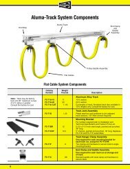
®<br />
<strong>DUCT</strong>-O-<strong>BAR</strong><br />
<strong>HD</strong> <strong>Series</strong> <strong>Conductor</strong> <strong>Systems</strong><br />
500, 1000 & 1500 Ampere Sizes<br />
A high amperage system of heavy duty conductor<br />
bars for large cranes and mobile equipment where<br />
strength, reliability and safety are required.<br />
•<br />
Lightweight aluminum conductor with<br />
stainless steel contact surface<br />
High strength bolted joints<br />
•<br />
Inverted “V” contact surface to ensure<br />
positive collector tracking<br />
Full support hanger clamps<br />
•<br />
Low maintenance — long life<br />
<strong>HD</strong>-500<br />
<strong>HD</strong>-1000<br />
<strong>HD</strong>-1500<br />
CAUTION<br />
MAKE CERTAIN POWER SUPPLY IS DISCON-<br />
NECTED BEFORE INSTALLING, REPAIRING,<br />
OR WORKING IN THE PROXIMITY OF ANY<br />
ELECTRICAL SYSTEM. ONLY QUALIFIED<br />
ELECTRICAL PERSONNEL SHOULD INSTALL<br />
OR REPAIR THESE PRO<strong>DUCT</strong>S.<br />
www.ductowire.com
®<br />
<strong>Conductor</strong> Bar Selection<br />
Determining Ampere Load<br />
The conductor selected must be large enough to carry the<br />
necessary ampere load safely without undue heating. To<br />
compute the ampere load, proceed as follows:<br />
1. List the horsepower of all motors used in the<br />
application.<br />
2. Determine the voltage and type of current that will feed<br />
the conductor. For example: 230v dc 2 wire; 460v ac 3<br />
phase; etc.<br />
3. Refer to the Horsepower Conversion Table and convert<br />
the horsepower to amperes.<br />
4. Prepare the ampere load figure that will be used to size<br />
the conductors as follows:<br />
List the full load ampere rating of each motor used on<br />
the crane or monorail unit. Determine the duty cycle<br />
from the following paragraphs and apply the<br />
corresponding factor.<br />
Average Duty — Class C Crane Service<br />
Moderate use during the work day. Five to ten lifts per<br />
hour. Not over 50% of the lift at rated capacity. Use a<br />
factor of 100% of the calculated ampere load.<br />
Heavy Duty — Class D Crane Service<br />
Used continually during the work day and usually for<br />
more than one shift. Loads of 50% of rated capacity or<br />
more handled constantly during the work period. Use a<br />
factor of 110% of the calculated ampere load.<br />
Severe Duty — Class E and F Crane Service<br />
Handles loads approaching 100% of the capacity all<br />
during the work period and for more than one shift. This<br />
includes large, heavy duty units such as bucket cranes,<br />
magnet lift cranes, cement or steel handling cranes.<br />
Use a factor of 120% of the calculated ampere load.<br />
Horsepower Conversion Table<br />
3 Phase AC — 60 Cycle Direct Current<br />
Amperes<br />
Amperes<br />
H.P. 230v 460v 575v 230v<br />
1/2 2 1 .8 2.7<br />
3/4 2.8 1.4 1.1 3.8<br />
1 3.6 1.8 1.4 4.7<br />
1-1/2 5.2 2.6 2.1 6.6<br />
2 6.8 3.4 2.7 8.5<br />
3 9.6 4.8 3.9 12.2<br />
5 15.2 7.6 6.1 20<br />
7-1/2 22 11 9 29<br />
10 28 14 11 38<br />
15 42 21 17 55<br />
20 54 27 22 72<br />
25 68 34 27 89<br />
30 80 40 32 106<br />
40 104 52 41 140<br />
50 130 65 52 173<br />
60 154 77 62 206<br />
75 192 96 77 255<br />
100 248 124 99 341<br />
125 312 156 125 425<br />
150 360 180 144 506<br />
200 480 240 192 675<br />
Induction Type Squirrel Cage and Wound Rotor Motors<br />
The Horsepower Conversion Table is taken from the 1996<br />
NEC Article 430. The values are for motors running at<br />
usual speeds with normal torque characteristics. Motors<br />
built for especially low speeds or high torques may require<br />
more running current, and multi-speed motors will have<br />
full-load current varying with speed. In these cases, use<br />
the higher current rating from the nameplate.<br />
The voltages listed are rated motor voltages. The current<br />
listed shall be permitted for system voltage ranges of 110<br />
to 120, 220 to 240, 440 to 480, and 550 to 600 volts.<br />
Motors rated at 208v ac should increase the 230 volt<br />
column figures by 10%.<br />
For motors that are wound for single or double phase<br />
operation, use the nameplate rating. For older slip ring<br />
motors or models that have secondary windings be sure to<br />
obtain both primary and secondary current ratings.<br />
Secondary windings may also need separate conductors<br />
or cables when updating the electrification.<br />
2
®<br />
Single vs. Multiple Cranes<br />
The procedures used to size single cranes are different<br />
from those used to size multiple cranes.<br />
Single Units<br />
1. For one motor, use 100% of the motor nameplate full<br />
load ampere rating.<br />
2. For multiple motors on a single crane, the minimum<br />
ampacity of the power supply conductors shall be 100%<br />
of the nameplate full-load ampere rating of the largest<br />
motor or group of motors for any single crane motion<br />
plus 50% of the nameplate full-load amp rating of the<br />
remaining motors.<br />
Multiple Units<br />
1. For multiple cranes supplied by a common conductor,<br />
first estimate the individual unit amp load as in Step 2 of<br />
Single Units. Then multiply the total amp load of all units<br />
by the following table.<br />
2. Additional loads such as heating, lighting, or air<br />
conditioning for cabs of large overhead cranes shall be<br />
provided for by adding the amperage load of this<br />
material to the motor load.<br />
Number of Cranes<br />
Demand Factors<br />
Demand Factor<br />
2 0.95<br />
3 0.91<br />
4 0.87<br />
5 0.84<br />
6 0.81<br />
7 0.78<br />
Determining Voltage Drop<br />
After categorizing the units and totaling the electrical load,<br />
we are ready to size the conductor and calculate the<br />
voltage drop to confirm the proper selection. Use the<br />
following problem illustration to assist in selecting and<br />
sizing the proper <strong>HD</strong> conductor for your system.<br />
For example, use a crane runway of 800 feet in length,<br />
two cranes on the runway, each with motors rated at 100<br />
h.p. for the hoist, 10 h.p. on the trolley and two 10 h.p.<br />
motors on the bridge. The operation is heavy duty and the<br />
ambient temperature reaches 100°F in the summer. The<br />
supply voltage is 460 vac, 3 phase 60 cycle. The units are<br />
radio controlled from the floor.<br />
The total amperage load for each unit is:<br />
(1) 100 h.p. hoist @ 124 amp x 100% 124.0 amps<br />
(1) 10 h.p. trolley @ 14 amp x 50% 7.0 amps<br />
(2) 10 h.p. bridge @ 14 amp x 50% 14.0 amps<br />
145.0 amps<br />
The total amp load for each unit is 145. The runway load<br />
for two cranes is then reduced by the Demand Factor from<br />
the table above.<br />
145 + 145 = 290 x 0.95 = 275.5 amps.<br />
According to CMAA, the voltage drop to the unit motors<br />
shall not be more than 3% from the power taps to the load<br />
at the farthest point on the conductor run. To determine<br />
the voltage drop use the appropriate formula in the<br />
following table.<br />
V<br />
L<br />
I<br />
Z<br />
R<br />
= Voltage drop<br />
= Distance in feet from power feed to end of<br />
conductor<br />
= Total amperes drawn as determined by the<br />
Horsepower Conversion Table on page 2.<br />
= ac impedance from the <strong>Conductor</strong> Engineering<br />
Data Table below<br />
= dc resistance from the <strong>Conductor</strong> Engineering<br />
Data Table below<br />
Current Type<br />
Formula<br />
AC 3 phase 60 cycle V = L x I x Z x 1.73<br />
DC 2 wire system V = L x I x R x 2<br />
Based on the amp load, select the <strong>HD</strong>-500-3 conductor to<br />
use in the voltage drop calculation. From the AC 3 phase<br />
formula, we have the distance (L) = 400 ft., the total amp<br />
draw (I) = 275.5 amps, and the ac impedance value<br />
(Z) = 0.000070.<br />
Putting these values into the formula, V = L x I x Z x 1.73,<br />
the voltage drop (V) is:<br />
V = 400 x 275.5 x 0.000070 x 1.73 = 13.34<br />
To obtain the percentage of voltage drop, divide the<br />
voltage drop figure (13.34) by the supply voltage.<br />
13.34 ÷ 460 = 0.029 or 2.9%<br />
3
®<br />
This is within the CMAA recommended 3% voltage drop<br />
standard for crane runway conductors. The table below<br />
indicates the maximum voltage drop values that result in a<br />
3% voltage drop to voltage supply ratio. When selecting a<br />
conductor, the voltage drop should be equal or less than<br />
the values shown.<br />
Ambient Temperature Adjustment<br />
If the conductors are to be located where the ambient air<br />
temperature is unusually high, the current carrying<br />
capacity of the conductor is reduced. For those cases,<br />
multiply the current capacity of the selected conductor by<br />
the derating factor in the following table.<br />
Maximum Allowable Voltage Drop<br />
Temperature Derating Table<br />
Supply Voltage<br />
Voltage Drop (V)<br />
Ambient Air Temperature<br />
Derating Factor<br />
460v ac 13.8<br />
230v ac or dc 6.9<br />
575v ac 17.2<br />
100°F 95%<br />
130°F 75%<br />
160°F* 50%<br />
* At this ambient temperature it will be neccessary to use the higher<br />
rated conductor cover, XHT rated at 280°F.<br />
<strong>Conductor</strong> Engineering Data Table<br />
Resistance<br />
Weight Continuous Coefficient of<br />
<strong>Conductor</strong> per 20 ft. Current Linear Expansion AC (Z) DC (R)<br />
Bar Number Description section (lbs.) Rating (AC) per °F Ohms/ft. Ohms/ft. MCM<br />
<strong>HD</strong>-500-3 Extruded Aluminum 12.6 500 .000013 .000070 .000044 425.3<br />
with stainless steel cap<br />
<strong>HD</strong>-1000-3 Extruded Aluminum 33.0 1000 .000013 .000040 .000014 1311.4<br />
with stainless steel cap<br />
<strong>HD</strong>-1500-3 Extruded Aluminum 43.8 1500 .000013 .000030 .000009 1916.2<br />
with stainless steel cap<br />
Collector Sizing<br />
In systems using high amperage conductors, there are<br />
many installations which have multiple crane bridges.<br />
Experience has shown that individual crane bridges vary<br />
in horse power rating and current draw. Therefore, it is<br />
very important to size the collectors for the individual<br />
crane bridges when multiple units are encountered.<br />
Other factors to consider when selecting collectors include<br />
the Class of Service of the cranes, whether there are units<br />
which have magnet lifts, and whether electronic controls<br />
are used in the crane operation.<br />
Cranes which are used in Class D, E, or F service will<br />
have heavier service requirements than those used in<br />
standby or standard operation. The mechanical wear on<br />
collectors is much greater when heavier loads, more lifts<br />
per hour, or multiple shifts are involved. For these<br />
situations, collectors with greater shoe wear and adequate<br />
current draw should be selected.<br />
Whenever a crane is used with a magnet lift, the Crane<br />
Manufacturer’s Association of America recommends that<br />
tandem collectors be used for safety reasons. No magnet<br />
load should ever be in danger of being dropped due to a<br />
skip in the runway electrification.<br />
Since most electronic control systems run on lower<br />
voltages than the crane power circuit, and are subject to<br />
loss of signal due to corrosion or build-up of deposits on<br />
the conductors, control manufacturers recommend the use<br />
of tandem collectors for electronic circuits as well.<br />
If the application calls for continuous use of the largest<br />
motor or motors when the unit is stationary, such as the<br />
hoisting motion on large loaders, there is the possibility of<br />
overheating the conductors. Contact the factory regarding<br />
derating of the collectors.<br />
4
®<br />
Expansion Gaps<br />
Expansion gaps should be placed at intervals determined<br />
by 1) the expansion rate of the metal in the conductor,<br />
2) the variation in ambient temperature which can occur at<br />
the conductor location over a full year of operation, and<br />
3) the location of building expansion joints.<br />
The <strong>HD</strong> conductor material is aluminum with a stainless<br />
steel cap on the running surface. Aluminum is the primary<br />
metal for calculating the total expansion. The expansion<br />
rate for aluminum is: 1.56"/100 ft./100°F.<br />
The formula used to calculate the total conductor<br />
expansion is:<br />
Total expansion (inches) = 1.56 x X/100' x Y/100°F,<br />
where X is the runway length in feet and Y is the total<br />
temperature variation in °F.<br />
1. System Located Indoors<br />
Calculate the expansion for a system that is 800 ft. in<br />
length, with an indoor temperature variation of 50°F.<br />
Total Expansion = 1.56 x 800'/100' x 50°F/100°F = 6.24".<br />
2. System Located Outdoors<br />
Calculate the expansion for a system that is 950 ft. in<br />
length with an outdoor temperature variation of 110°F.<br />
Total Expansion = 1.56 x 950'/100' x 110°F/100°F = 16.3"<br />
3. Determine the Number of Expansion Gap Assemblies<br />
After calculating the actual expansion of the runway<br />
conductor system, use the following rule of thumb to pick<br />
the number of expansion gap assemblies:<br />
A. Under 3" of expansion, use no expansion assemblies,<br />
but do install one anchor clamp assembly at the center<br />
of each conductor run.<br />
B. From 3" to 6" of expansion, use one expansion<br />
assembly in the center of the conductor run.<br />
C. From 6" to 9" of expansion, use two expansion<br />
assemblies in each conductor run. Locate them at 1/3<br />
of the runway length in from each end.<br />
D. For systems with more than 9" of expansion, use one<br />
expansion assembly for each 3" of expansion.<br />
4. Anchors<br />
Anchor clamps or anchor pins are required at midpoint on<br />
all systems without expansion gaps and halfway between<br />
gaps and from gaps to the ends of systems with multiple<br />
gaps. See the <strong>HD</strong> Installation Instructions on anchor<br />
locations. If anchors are not correctly placed and used, the<br />
expansion gap settings will be lost.<br />
The maximum gap setting for <strong>HD</strong>-500 systems is 3.5", and<br />
there are two 1.75" gaps to set. The maximum gap setting<br />
for the <strong>HD</strong>-1000 and <strong>HD</strong>-1500 systems is 3.25", and there<br />
is one gap to set.<br />
See the <strong>HD</strong> Installation bulletins for specific<br />
instructions.<br />
CON<strong>DUCT</strong>OR RUNWAY<br />
1<br />
⁄4 Runway Length<br />
Anchor<br />
Point<br />
Power<br />
Feed<br />
Expansion<br />
Assembly 10'<br />
1<br />
⁄2<br />
Runway Length<br />
Hanger Clamp Bracket<br />
• • • •<br />
• • • • • •<br />
• • • •<br />
• • • • • •<br />
• • • •<br />
• • • • • •<br />
End Cap<br />
20 ft. <strong>Conductor</strong><br />
5' Support Spacing<br />
Joint<br />
Anchor<br />
Point<br />
End Cap<br />
<strong>HD</strong>-500 Schematic Diagram<br />
CON<strong>DUCT</strong>OR RUNWAY<br />
1<br />
⁄2 Runway Length<br />
1<br />
⁄4 Runway Length<br />
1<br />
⁄4 Runway Length<br />
Joint<br />
Anchor<br />
Point<br />
Expansion<br />
Assembly 10'<br />
• • •<br />
• • •<br />
•<br />
•<br />
•<br />
• • • • • • • •<br />
•<br />
•<br />
•<br />
•<br />
•<br />
•<br />
•<br />
• •<br />
• •<br />
• •<br />
•<br />
•<br />
•<br />
• •<br />
• • •<br />
•<br />
•<br />
•<br />
•<br />
•<br />
• •<br />
• •<br />
• •<br />
•<br />
•<br />
•<br />
•<br />
•<br />
•<br />
•<br />
•<br />
End Cap<br />
Hanger<br />
Support<br />
10'<br />
Support<br />
Spacing<br />
Power Feed<br />
Anchor<br />
Point<br />
End Cap<br />
<strong>HD</strong>-1000 Schematic Diagram<br />
5
®<br />
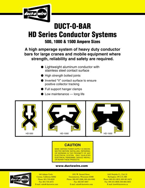
Installation Dimensions — 500 Amp<br />
5' 0"<br />
3" 3"<br />
3/8" Diameter Stud<br />
Spacing Required<br />
Mounting<br />
Bracket<br />
9" Joint<br />
15" Power Feed<br />
Hanger with Insulator<br />
1-1/8"<br />
1-1/2"<br />
Hanger<br />
Clamp<br />
Insulator<br />
(Optional)<br />
<strong>Conductor</strong><br />
Assembly<br />
Joint Cover<br />
Collector<br />
4"<br />
Contact<br />
Surface<br />
Collector<br />
Assembly<br />
1" Square Post<br />
1-7/8"<br />
<strong>HD</strong>-500-3 System — Support Spacing Requirements<br />
Typical System Installation — 500 Amp<br />
Basic <strong>HD</strong> <strong>Conductor</strong>s — 500 Amp<br />
Assembly Catalog Number<br />
20-Foot Lengths<br />
Weight (Lbs) Indoor Use Outdoor Use High Temperature Use<br />
160°F Max. 160°F with UV Additive 280°F Max.<br />
12.6 <strong>HD</strong>-500-3 <strong>HD</strong>-500-3-SC <strong>HD</strong>-500-3XHT<br />
Collectors for 500 Amp <strong>Conductor</strong>s<br />
3"<br />
11"<br />
28"<br />
1-1/8"<br />
4"<br />
14" 14"<br />
<strong>HD</strong>P-150-V5<br />
Pantograph Collector, Single Shoe<br />
<strong>HD</strong>P-500-VT6<br />
Pantograph Tandem Collector<br />
<strong>HD</strong>P <strong>Series</strong> Pantograph Collector Assemblies<br />
Catalog No. Lbs. Description<br />
<strong>HD</strong>P-150-V5 2.5 150 amp Single Shoe — Vertical Mount<br />
<strong>HD</strong>P-150-V5-BR 5.4 150 amp Single Shoe — Vertical, Bronze<br />
<strong>HD</strong>P-150-L5 2.8 150 amp Single Shoe — Lateral Mount<br />
<strong>HD</strong>P-300-VT5 5.1 300 amp Double Shoe — Vertical Mount<br />
<strong>HD</strong>P-300-VT5-BR 9.9 300 amp Double Shoe — Vertical, Bronze<br />
<strong>HD</strong>P-300-LT5 5.3 300 amp Double Shoe — Lateral Mount<br />
<strong>HD</strong>P <strong>Series</strong> Pantograph Collector Assemblies<br />
Catalog No. Lbs. Description<br />
<strong>HD</strong>P-250-V6 2.7 250 amp Single Shoe — Vertical Mount<br />
<strong>HD</strong>P-250-V6-BR 5.7 250 amp Single Shoe — Vertical, Bronze<br />
<strong>HD</strong>P-250-LT6 2.8 250 amp Single Shoe — Lateral Mount<br />
<strong>HD</strong>P-500-VT6 5.6 500 amp Double Shoe — Vertical Mount<br />
<strong>HD</strong>P-500-VT6-BR 10.2 500 amp Double Shoe — Vertical, Bronze<br />
<strong>HD</strong>P-500-LT6 5.7 500 amp Double Shoe — Lateral Mount<br />
For special pigtail lengths, contact the factory.<br />
6
®<br />
Installation Dimensions — 1000 & 1500 Amp<br />
4"<br />
Min.<br />
4"<br />
Min.<br />
5/8" Dia. Stud<br />
36"<br />
2"<br />
Mounting<br />
Bracket<br />
2"<br />
Insulator<br />
(Optional)<br />
6-1/2"<br />
C L<br />
3"<br />
Contact<br />
Surface<br />
Hanger<br />
Clamp<br />
<strong>Conductor</strong><br />
Assembly<br />
12" 12"<br />
2-1/2" 2-1/2"<br />
6-1/4"<br />
Collector<br />
Assembly<br />
C L<br />
1" Square Post<br />
<strong>HD</strong>-1000-3 & <strong>HD</strong>-1500-3 <strong>Systems</strong><br />
Support Spacing Requirements<br />
Typical System Installation<br />
1000 & 1500 Amp<br />
Basic <strong>HD</strong> <strong>Conductor</strong>s — 1000 & 1500 Amp<br />
20-Foot Lengths Assembly Catalog Number<br />
Weight (Lbs) Indoor Use Outdoor Use<br />
33.0 <strong>HD</strong>-1000-3 <strong>HD</strong>-1000-3-SC<br />
20-Foot Lengths Assembly Catalog Number<br />
Weight (Lbs) Indoor Use Outdoor Use<br />
43.8 <strong>HD</strong>-1500-3 <strong>HD</strong>-1500-3-SC<br />
Collectors for 1000 & 1500 Amp <strong>Conductor</strong>s<br />
18''<br />
36''<br />
18''<br />
6-1/4"<br />
<strong>HD</strong>P-1000-VT6<br />
Pantograph Collector, Double Shoe<br />
<strong>HD</strong>-600-TPC<br />
Pantograph Collector, Double Shoe<br />
<strong>HD</strong>P <strong>Series</strong> Pantograph Collector Assemblies<br />
Catalog No. Lbs. Description<br />
<strong>HD</strong>P-250-V6 2.7 250 amp Single Shoe — Vertical Mount<br />
<strong>HD</strong>P-250-V6-BR 5.7 250 amp Single Shoe — Vertical, Bronze<br />
<strong>HD</strong>P-250-LT6 2.8 250 amp Single Shoe — Lateral Mount<br />
<strong>HD</strong>P-500-VT6 5.6 500 amp Double Shoe — Vertical Mount<br />
<strong>HD</strong>P-500-VT6-BR 10.2 500 amp Double Shoe — Vertical, Bronze<br />
<strong>HD</strong>P-500-LT6 5.7 500 amp Double Shoe — Lateral Mount<br />
<strong>HD</strong>P-1000-VT6 11.3 1000 amp 4-Head — Vertical Mount<br />
<strong>HD</strong> <strong>Series</strong> Pantograph Collector Assemblies<br />
Catalog No. Lbs. Description<br />
<strong>HD</strong>-300-PC 6.1 300 amp Single Shoe — Vertical Mount<br />
<strong>HD</strong>-600-TPC 12.3 600 amp Double Shoe — Vertical Mount<br />
For special pigtail lengths, contact the factory.<br />
7
®<br />
Weight<br />
<strong>HD</strong>-500 <strong>Systems</strong> Catalog Number Pounds Description<br />
B-100-BR<br />
Angle Brackets for Web Mounting<br />
B-100-BR7B 1.18 Bracket with gusset support, 14-1/4" long.<br />
B-100-BR13B 1.57 Bracket with gusset support, 20-1/4" long.<br />
Welded Angle Iron Brackets<br />
3/16" x 1-1/2" x 24". Number of hanger holes<br />
determined by conductor runs. Minimum web<br />
height 10". Bracket drawings available.<br />
<strong>HD</strong>-T1BR-B1-500 4.78 Bracket with red primer, 8" vertical leg drilled for<br />
two 5/8" bolts spaced 3" apart.<br />
<strong>HD</strong>-T1BR-W1-500 4.78 Bracket without primer or mounting holes.<br />
FE-908-2SF<br />
FE-908-2SFG<br />
Snap-In Hanger Assemblies<br />
FE-908-2SF .11 Zinc plated steel hanger.<br />
FE-908-2SFE .11 Epoxy coated steel hanger.<br />
FE-908-2SFS .11 Stainless steel hanger with stainless steel<br />
hardware.<br />
FE-908-2SFG .20 Zinc plated steel hanger with insulator.<br />
FE-908-2SFFG .20 Epoxy coated steel hanger with insulator.<br />
FE-908-2SFSG .20 Stainless steel hanger with insulator and<br />
stainless steel hardware.<br />
<strong>HD</strong>-500-2FF<br />
<strong>HD</strong>-500-2FG<br />
Cross Bolt Hanger Assemblies<br />
<strong>HD</strong>-500-2FF .24 Zinc plated steel hanger.<br />
<strong>HD</strong>-500-2FFE .24 Epoxy coated steel hanger.<br />
<strong>HD</strong>-500-2FG .32 Zinc plated steel hanger with insulator.<br />
<strong>HD</strong>-500-2FFG .32 Epoxy coated steel hanger with insulator.<br />
Anchor Clamp Assemblies<br />
Clamps on both sides of a hanger at selected<br />
locations.<br />
<strong>HD</strong>-500-2FEA .36 Two-piece epoxy coated anchor set.<br />
Bolted Joint Assembly<br />
<strong>HD</strong>-500-1D .37 Installs at the junction of two conductors. The<br />
grooved header bar with four bolts provides<br />
perfect alignment and strong holding power.<br />
Estimate joint covers for all joints except when<br />
using a power feed.<br />
Joint/Power Feed Cover<br />
<strong>HD</strong>-500-3ER .37 Use the joint cover with each bolted joint<br />
assembly. A cover is supplied with each power<br />
feed assembly. There are knockouts at each<br />
end for cable entry.<br />
8
®<br />
Weight<br />
<strong>HD</strong>-500 <strong>Systems</strong> Catalog Number Pounds Description<br />
Power Feed Assembly with Cover<br />
<strong>HD</strong>-500-3CP .84 Takes the place of a bolted joint at a selected<br />
power feed location. The part number includes<br />
an <strong>HD</strong>-500-3ER cover. Each lug holds up to a<br />
1/0 power cable.<br />
Bolts: 3/8 - 16 x 1-1/2"<br />
Collector Mounting Post<br />
FC-TB1 3.25 Mounting Post with Hardware — 18" long.<br />
Mounting plate is 4" square with 3" hole spacing<br />
for <strong>HD</strong>P-<strong>Series</strong> Collectors.<br />
Contact factory for special lengths or finishes.<br />
End Cover<br />
<strong>HD</strong>-500-3GC .05 Flexible PVC End Cover, black.<br />
For all <strong>HD</strong>-500-3 conductors.<br />
Expansion Gap Assembly<br />
Each assembly consists of a ten-foot conductor<br />
bar, insulating cover, guide assembly, two gap<br />
openings, four power feeds and jumper cables.<br />
Anchor sets and instructions are included with<br />
the assembly.<br />
<strong>HD</strong>-500-3H10 12.0 Expansion section, orange PVC cover.<br />
<strong>HD</strong>-500-3H10-SC 12.0 Same with gray PVC outdoor cover.<br />
<strong>HD</strong>-500-3H10XT 12.0 Same with yellow polycarbonate high<br />
temperature cover. Rated to 280°F.<br />
Isolating Section Assembly<br />
Each assembly consists of a ten-foot section of<br />
conductor with two air gaps bridged with<br />
phenolic gap pieces and a power feed for the<br />
center section. Center section is longer than a<br />
tandem collector to prevent bridging power<br />
across the isolation gap.<br />
<strong>HD</strong>-500-3IS10 10.0 Isolating section, orange PVC cover.<br />
<strong>HD</strong>-500-3IS10-SC 10.0 Same with gray PVC outdoor cover.<br />
<strong>HD</strong>-500-3IS10-XT 10.0 Same with yellow polycarbonate high<br />
temperature cover. Rated to 280°F.<br />
Electric Joint Compound<br />
EJC 1.2 1 pint size. Estimate one for each 500 ft. of 3<br />
phase conductor run.<br />
9
®<br />
Weight<br />
<strong>HD</strong>-1000 & 1500 <strong>Systems</strong> Catalog Number Pounds Description<br />
Welded Angle Iron Brackets<br />
3/16" x 2" angle iron material. Number of hanger<br />
holes determined by conductor runs. Bracket<br />
drawings available. Minimum web height 10".<br />
<strong>HD</strong>-T1BR-B-1000 7.0 24" Bracket with red primer, 8" vertical leg<br />
drilled for two 5/8" bolts spaced 3" apart.<br />
<strong>HD</strong>-T1BR-W-1000 7.0 Same as above without primer or mounting holes.<br />
<strong>HD</strong>-T1BR-B-27 7.6 27" Bracket with red primer, 8" vertical leg<br />
drilled for two 5/8" bolts spaced 3" apart.<br />
<strong>HD</strong>-T1BR-W-27 7.6 Same as above without primer or mounting holes.<br />
Bolted Hanger Assemblies<br />
All hangers have 5/8" mounting bolts.<br />
<strong>HD</strong>-1000-2F .84 Zinc plated steel hanger.<br />
<strong>HD</strong>-1000-2FE .86 Epoxy coated steel hanger.<br />
<strong>HD</strong>-1000-2FG 1.24 Zinc plated steel hanger with insulator.<br />
<strong>HD</strong>-1000-2FGE 1.26 Epoxy coated steel hanger with insulator.<br />
Anchor Clamp Assemblies<br />
All anchors have 5/8" mounting bolts. Anchors<br />
are bracket mounted and replace hangers at<br />
designated locations.<br />
<strong>HD</strong>-1000-2FEA .86 Epoxy coated, no spacers on cross-bolts.<br />
<strong>HD</strong>-1000-2FGEA 1.26 Epoxy coated with insulator, no spacers.<br />
Bolted Joint Assembly<br />
<strong>HD</strong>-1000-3D 1.98 Grooved header bar and six bolts provides for<br />
perfect alignment and strong holding power. For<br />
both <strong>HD</strong>-1000 and <strong>HD</strong>-1500 systems. Estimate<br />
joint covers separately.<br />
Joint/Power Feed Cover<br />
<strong>HD</strong>-1000-3ER 1.3 Use with <strong>HD</strong>-1000 systems.<br />
<strong>HD</strong>-1500-3ER 1.43 Use with <strong>HD</strong>-1500 systems.<br />
Power Feed Assembly with Cover<br />
Takes the place of a bolted joint at a selected<br />
power feed location.The part number includes<br />
an <strong>HD</strong>-1000-3ER or <strong>HD</strong>-1500-3ER cover.<br />
<strong>HD</strong>-1000-3CP 3.48 Two 350 mcm cable lugs for <strong>HD</strong>-1000 systems.<br />
<strong>HD</strong>-1500-3CP 3.62 Two 500 mcm cable lugs for <strong>HD</strong>-1500 systems.<br />
10
®<br />
Weight<br />
<strong>HD</strong>-1000 & 1500 <strong>Systems</strong> Catalog Number Pounds Description<br />
Bolts: 3/8 - 16 x 1-1/2"<br />
Collector Mounting Post<br />
FC-TB1 3.25 Mounting post with hardware — 18" long.<br />
Mounting plate is 4" square with 3" hole spacing<br />
for <strong>HD</strong>P-<strong>Series</strong> and <strong>HD</strong>-<strong>Series</strong> Collectors.<br />
Contact factory for special lengths or finishes.<br />
End Cover<br />
Flexible PVC, black.<br />
<strong>HD</strong>-1000-3GC .14 Cover for <strong>HD</strong>-1000 systems.<br />
<strong>HD</strong>-1500-3GC .16 Cover for <strong>HD</strong>-1500 systems.<br />
Expansion Gap Assemblies —<br />
10 Foot Section<br />
Each assembly consists of 10 feet of<br />
conductor, insulating cover, guide assembly,<br />
gap opening, power feeds and jumper<br />
cables. Anchor sets and instructions are<br />
included in the assembly.<br />
<strong>HD</strong>-1000-3H10 38.5 Assembly with orange cover for <strong>HD</strong>-1000.<br />
<strong>HD</strong>-1000-3H10-SC 38.5 Assembly with sun cover for <strong>HD</strong>-1000.<br />
<strong>HD</strong>-1500-3H10 44.0 Assembly with orange cover for <strong>HD</strong>-1500.<br />
<strong>HD</strong>-1500-3H10-SC 44.0 Assembly with sun cover for <strong>HD</strong>-1500.<br />
<strong>Wire</strong> Support<br />
<strong>HD</strong>-EXP-WSA 1.9 <strong>Wire</strong> support assembly for <strong>HD</strong>-1000 and<br />
<strong>HD</strong>-1500 expansion gap jumper cables.<br />
Isolation Assemblies — 10 Foot Section<br />
Each assembly consists of 10 feet of<br />
conductor, insulating cover, phenolic<br />
insulated gap pieces, and a power feed for<br />
the center section.<br />
<strong>HD</strong>-1000-3IS10 20.0 Assembly with orange cover for <strong>HD</strong>-1000.<br />
<strong>HD</strong>-1000-3IS10SC 20.0 Assembly with sun cover for <strong>HD</strong>-1000.<br />
<strong>HD</strong>-1500-3IS10 20.0 Assembly with orange cover for <strong>HD</strong>-1500.<br />
<strong>HD</strong>-1500-3IS10SC 20.0 Assembly with sun cover for <strong>HD</strong>-1500.<br />
Electric Joint Compound<br />
EJC 1.2 1 pint size. Estimate one for each 260 feet of<br />
3 phase conductor run.<br />
11
Expansion Gap Dimensions for Hanger and Bracket Locations<br />
Optional Hanger<br />
Area<br />
Insulators are installed at these locations<br />
if system uses insulated hangers.<br />
Center Mounting Bolt<br />
Bracket Location<br />
Located at 5' from<br />
either end of Assembly<br />
Optional Hanger<br />
Area<br />
5.56"<br />
5.56"<br />
13.19" 11.19" 12.06" 11.19"<br />
25"<br />
11.19" 12.06" 11.19" 13.19"<br />
Gap Location<br />
Gap Location<br />
10'0" Closed 10'3 1 ⁄2" Open<br />
<strong>HD</strong>-500-3H10<br />
Optional Hanger Area<br />
Optional Hanger Area<br />
18" Joint Cover 18" Joint Cover<br />
3'7"<br />
18" 8.5"<br />
18"<br />
1'2 1 ⁄2"<br />
10'0" Closed 10'3 1 ⁄4" Open<br />
<strong>HD</strong>-1000-3H10 & <strong>HD</strong>-1500-3H10<br />
Heated <strong>Conductor</strong> <strong>Systems</strong> for De-Icing Control<br />
Ice build-up on outdoor overhead cranes can cause the<br />
collectors to skip out of the conductor. To prevent this from<br />
happening, <strong>Duct</strong>-O-<strong>Wire</strong> provides a thermostatically<br />
controlled heater cable system that is engineered for each<br />
specific application.<br />
The heater cable is installed in the various conductors,<br />
and the circuit and cable size are formulated specifically to<br />
match the system length. The heater cable is constructed<br />
in such a way that individual conductor sections can be<br />
replaced without removing the entire heater cable.<br />
<strong>Duct</strong>-O-<strong>Wire</strong> maintains drawings of all heated systems in<br />
case replacement sections are needed to fit the original<br />
system. Records are also vital in case of additions to the<br />
system or revisions to the heater cable circuit become<br />
necessary.<br />
Contact the <strong>Duct</strong>-O-<strong>Wire</strong> sales department for details and<br />
pricing of the heated systems.<br />
®<br />
<strong>Duct</strong>-O-<strong>Wire</strong> representatives and distributors are located throughout the U.S.<br />
and Canada. Call the factory for the representative or distributor closest to you.<br />
Brochure <strong>HD</strong>-98<br />
Copyright 1998<br />
Printed in U.S.A.