Direct-Current Generators (.pdf) - the Alfred State College intranet site!
Direct-Current Generators (.pdf) - the Alfred State College intranet site!
Direct-Current Generators (.pdf) - the Alfred State College intranet site!

You also want an ePaper? Increase the reach of your titles
YUMPU automatically turns print PDFs into web optimized ePapers that Google loves.
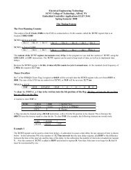
<strong>Direct</strong> <strong>Current</strong> Motors<br />
Chap 4. Electrical Machines by Wildi, 6 e<br />
Lecturer: R. Alba-Flores<br />
<strong>Alfred</strong> <strong>State</strong> <strong>College</strong><br />
Spring 2008
Single Phase Generator<br />
Two-phase generator<br />
Three-phase generator:
Generating an AC voltage<br />
A simple AC generator with a coil that rotates at 60 rev/min between<br />
<strong>the</strong> N and S poles of a permanent magnet is:<br />
• The coil is connected to two slip rings mounted on <strong>the</strong> shaft.<br />
• The slip rings are connected to an external load by means of two<br />
stationary brushes x and y
• As <strong>the</strong> coil rotates, a voltage in induced between its terminals A and D<br />
[ E = Blv (B flux density, l length of <strong>the</strong> conductor, v, speed of rotation) ]<br />
• This voltage appears between <strong>the</strong> brushes, and <strong>the</strong>refore across <strong>the</strong> load<br />
• The voltage is maximum when <strong>the</strong> coil is in its horizontal position<br />
• The induced voltage is minimum when <strong>the</strong> coil is in its vertical position<br />
• The coil polarity changes every time <strong>the</strong> coil makes half a turn
<strong>Direct</strong>-<strong>Current</strong> Generator<br />
If <strong>the</strong> brushes x and y could be switched from one slip ring to <strong>the</strong> o<strong>the</strong>r<br />
every time <strong>the</strong> polarity is about to change, we could obtain a voltage of<br />
constant polarity across <strong>the</strong> load.<br />
Brush x could be always positive, and brush y negative
This can be obtained by using a commutator<br />
A very simple commutator is a slip ring that is cut in half<br />
- One segment is connected to coil-end A<br />
- The o<strong>the</strong>r segment is connected to coil-end D<br />
- The commutator revolves with <strong>the</strong> coil and <strong>the</strong> voltage between<br />
<strong>the</strong> segments is pickup by two stationary brushes x and y
The voltage between brushes x and y<br />
pulsates but never changes polarity.<br />
Pulsating DC voltage
Improving <strong>the</strong> Pulsating DC voltage<br />
By increasing <strong>the</strong> number of coils and segments we can obtain<br />
a smoo<strong>the</strong>r DC voltage.<br />
• The coils are held in slots of a laminated iron cylinder.<br />
• The coils and <strong>the</strong> cylinder are <strong>the</strong> armature of <strong>the</strong> machine.<br />
This armature has 4 slots, 4 coils, and 4 commutator bars
Generator with an armature that has 4 slots, 4 coils and 4 commutator bars<br />
Physical construction<br />
Schematic diagram<br />
Smoo<strong>the</strong>r induced DC voltage<br />
Armature has rotated 45 o<br />
E xy = e b + e c = e a + e d
Schematic diagram of <strong>the</strong> armature and <strong>the</strong> voltages induced in<br />
a 12 coils, 12 slots, and 12 commutator bars
Small permanent magnet machine
Small wound–field machine<br />
(GEC Small Machines Ltd.)
In practical armature windings <strong>the</strong> coils and<br />
commutator segments are interconnected so that<br />
<strong>the</strong> conductors carry current all <strong>the</strong> time, and <strong>the</strong>re<br />
are usually several coils in series between <strong>the</strong><br />
brushes as shown in <strong>the</strong> previous figure (Small<br />
wound–field machine, GEC Small Machines Ltd.)
DC machine action in terms of magnetic forces<br />
Armature reaction<br />
A current i a<br />
angles to φ<br />
flowing in <strong>the</strong> armature will produce a flux φ a at right<br />
φ a this is known as <strong>the</strong> armature reaction flux
DC machine action in terms of magnetic forces<br />
The existence of an armature reaction flux, φ a, implies<br />
magnetization of <strong>the</strong> armature iron, which maybe<br />
represented by N and S poles.<br />
Form <strong>the</strong> Maxwell stress concept it follows that <strong>the</strong>re<br />
will be a torque on <strong>the</strong> armature tending to rotate its<br />
poles into alignment with <strong>the</strong> field poles.<br />
The armature winding and commutator, ensure that <strong>the</strong><br />
magnetic axis of <strong>the</strong> armature remains fixed in space<br />
while <strong>the</strong> armature material revolves.<br />
Therefore a steady torque is developed, which is<br />
unaffected by <strong>the</strong> rotation of <strong>the</strong> armature.
DC machine action in terms of magnetic forces
The armature and field circuits
In permanent–magnet machine <strong>the</strong> field flux φ is constant.<br />
In wound-field machines, <strong>the</strong> pole flux φ depends on <strong>the</strong> field or<br />
excitation voltage V f<br />
The current i f flowing in <strong>the</strong> field winding will produce a pole flux φ.<br />
With no armature current flowing, φ will be a function of i f only<br />
At constant speed e a is proportional to φ<br />
Magnetization curve or open-circuit<br />
characteristic<br />
Wound-field DC machine
Armature magnetomotive force (mmf) ( armature reaction )<br />
{ magnetomotive force or magnetic potential analog to<br />
electromotive force (emf) or voltage }
Magnetic field produced by <strong>the</strong> current<br />
flowing in <strong>the</strong> armature conductors<br />
Armature reaction distorts <strong>the</strong> field<br />
produced by <strong>the</strong> N-S poles
Commutating poles produces a mmf c<br />
of <strong>the</strong> armature<br />
that opposes <strong>the</strong> mmf a
Separately excited generator<br />
• Separately excited 2-pole generator.<br />
• The N-S field poles are created by <strong>the</strong> current<br />
flowing in <strong>the</strong> field windings
Separately excited DC generator curves<br />
Flux per pole versus exciting current<br />
The rated voltage of a DC<br />
generator is usually a little<br />
above <strong>the</strong> knee of <strong>the</strong><br />
saturation curve<br />
Saturation curve of a DC generator
Self-excited shunt generator<br />
Shunt<br />
field<br />
A shunt field is connected in parallel with <strong>the</strong> armature winding<br />
• When a shunt generator is started up, a small voltage is induced in <strong>the</strong><br />
armature, due to <strong>the</strong> remanent flux in <strong>the</strong> poles.<br />
• This voltage produces a small exciting current I x in <strong>the</strong> shunt field.<br />
• The resulting small magnetomotive force (mmf) acts on <strong>the</strong> same<br />
direction as <strong>the</strong> remanent flux, increasing it.<br />
• This will increase Eo and also I x , increasing even more Eo
Controlling <strong>the</strong> voltage of a shunt generator<br />
• Controlling <strong>the</strong> generator induced voltage can be done by varying <strong>the</strong><br />
exciting current by means of rheostat connected in series with <strong>the</strong> shunt<br />
field.<br />
• A rheostat is a resistor with an adjustable sliding contact.
No-load value of <strong>the</strong> induced voltage Eo<br />
Knowing <strong>the</strong> saturation curve of <strong>the</strong> generator and <strong>the</strong> total resistance R t of <strong>the</strong><br />
shunt field circuit <strong>the</strong> no-load voltage can be determined.<br />
If R t continue to increase, a critical value will be reached, and after this no<br />
induced voltage will be generated.
Equivalent circuit of a DC generator<br />
• The armature winding contains a set of identical coils, all of which possess<br />
a certain resistance.<br />
• The total armature resistance, Ro, is <strong>the</strong> one that exists when <strong>the</strong><br />
machine is stationary.<br />
• Ro is usually very small < 0.01 ohms
Separately excited generator under load.
Compound generator under load
Typical load characteristics of DC generators
Circuit representation of series,<br />
shunt, and compound DC<br />
machines and <strong>the</strong>ir torque vs<br />
speed characteristic.